model t27313 - grizzlycdn2.grizzly.com/manuals/t27313_m.pdfthe model t27313 wood lathe copy...
TRANSCRIPT

MODEL T27313WOOD LATHE COPY ATTACHMENT
OWNER'S MANUAL(For models manufactured since 03/16)
COPYRIGHT © MARCH, 2015 BY GRIZZLY INDUSTRIAL, INC. REVISED APRIL, 2016 (MN)WARNING: NO PORTION OF THIS MANUAL MAY BE REPRODUCED IN ANY SHAPE
OR FORM WITHOUT THE WRITTEN APPROVAL OF GRIZZLY INDUSTRIAL, INC.#BB17314 PRINTED IN CHINA V2.04.16
(Model T27313 shown installed on Model G0733)

This manual provides critical safety instructions on the proper setup, operation, maintenance, and service of this machine/tool. Save this document, refer to it often, and use it to instruct other operators.
Failure to read, understand and follow the instructions in this manual may result in fire or serious personal injury—including amputation, electrocution, or death.
The owner of this machine/tool is solely responsible for its safe use. This responsibility includes but is not limited to proper installation in a safe environment, personnel training and usage authorization, proper inspection and maintenance, manual availability and compre-hension, application of safety devices, cutting/sanding/grinding tool integrity, and the usage of personal protective equipment.
The manufacturer will not be held liable for injury or property damage from negligence, improper training, machine modifications or misuse.
Some dust created by power sanding, sawing, grinding, drilling, and other construction activities contains chemicals known to the State of California to cause cancer, birth defects or other reproductive harm. Some examples of these chemicals are:
• Lead from lead-based paints.• Crystalline silica from bricks, cement and other masonry products.• Arsenic and chromium from chemically-treated lumber.
Your risk from these exposures varies, depending on how often you do this type of work. To reduce your exposure to these chemicals: Work in a well ventilated area, and work with approved safety equip-ment, such as those dust masks that are specially designed to filter out microscopic particles.

INTRODUCTION ............................................................................................................................... 2Machine Description ................................................................................................................... 2Contact Info ................................................................................................................................ 2Manual Accuracy ........................................................................................................................ 2Controls & Components ............................................................................................................. 3
SECTION 1: SAFETY ....................................................................................................................... 4Safety Instructions for Machinery ............................................................................................... 4Additional Safety for Copy Attachments .................................................................................... 6
SECTION 2: SETUP ......................................................................................................................... 7Unpacking .................................................................................................................................. 7Needed for Setup ....................................................................................................................... 7Inventory ..................................................................................................................................... 7Cleanup ...................................................................................................................................... 8Site Considerations .................................................................................................................... 9Assembly .................................................................................................................................. 10
SECTION 3: OPERATIONS ........................................................................................................... 14Operation Overview.................................................................................................................. 14Workpiece Inspection ............................................................................................................... 15Copy Attachment Tips .............................................................................................................. 15Copy Stylus .............................................................................................................................. 16Cutting Tool .............................................................................................................................. 16Basic Operation ........................................................................................................................ 17
SECTION 4: ACCESSORIES ......................................................................................................... 19
SECTION 5: MAINTENANCE......................................................................................................... 20Schedule .................................................................................................................................. 20Cleaning & Protecting .............................................................................................................. 20Lubrication ................................................................................................................................ 20
SECTION 6: SERVICE ................................................................................................................... 21Troubleshooting ........................................................................................................................ 21Cable Tension .......................................................................................................................... 22Gib Adjustment ......................................................................................................................... 22
SECTION 7: PARTS ....................................................................................................................... 23Main Breakdown....................................................................................................................... 23Longitudinal Drive Breakdown ................................................................................................. 25Carriage Breakdown................................................................................................................. 26
WARRANTY & RETURNS ............................................................................................................. 29
Table of Contents

-2- Model T27313 (Mfd. Since 12/15)
INTRODUCTION
We are proud to provide a high-quality owner’s manual with your new machine!
We made every effort to be exact with the instruc-tions, specifications, drawings, and photographs in this manual. Sometimes we make mistakes, but our policy of continuous improvement also means that sometimes the machine you receive is slightly different than shown in the manual.
If you find this to be the case, and the difference between the manual and machine leaves you confused or unsure about something, check our website for an updated version. We post current manuals and manual updates for free on our web-site at www.grizzly.com.
Alternatively, you can call our Technical Support for help. Before calling, make sure you write down the Manufacture Date and Serial Number from the machine ID label (see below). This information is required for us to provide proper tech support, and it helps us determine if updated documenta-tion is available for your machine.
Manufacture Date
Serial Number
Manual Accuracy
We stand behind our machines! If you have ques-tions or need help, contact us with the information below. Before contacting, make sure you get the serial number and manufacture date from the machine ID label. This will help us help you faster.
Grizzly Technical Support1815 W. Battlefield
Springfield, MO 65807Phone: (570) 546-9663
Email: [email protected]
We want your feedback on this manual. What did you like about it? Where could it be improved? Please take a few minutes to give us feedback.
Grizzly Documentation ManagerP.O. Box 2069
Bellingham, WA 98227-2069Email: [email protected]
Contact Info
The Model T27313 Wood Lathe Copy attachment is part of Grizzly’s growing family of fine wood-working and metalworking machinery. When used according to the guidelines stated in this manual, you can expect years of trouble-free, enjoyable operation.
The Model T27313 is a wood lathe duplica-tor capable of mass-producing many shapes of the same design. The T27313 is designed to be mounted to the G0733, G0462, G0584 and G5979 wood lathes. Mounting hardware and cut-ting tool are provided with the Copy attachment.
Machine Description

Model T27313 (Mfd. Since 12/15) -3-
Controls & Components
Refer to Figure 1 and the following descriptions to become familiar with the basic controls of this machine.
To reduce your risk of serious injury, read this entire manual BEFORE using machine.
D. Tool Locking Collar: Hardware that keeps cutting tool locked in place.
E. Quill: Moves cutting tool mounted in the car-riage toward or away from the workpiece.
F. Carriage: Main housing for quill, cutting tool, and tool locking collar. Moves longitudinally along copy attachment bed.
G. Stylus: Controls depth of cut.
H. Crossfeed Handwheel: Controls crossfeed leadscrew, which sets maximum cutting tool depth. Turning clockwise decreases cutting depth and turning counterclockwise increas-es cutting depth.
I. Tail Center Adjustment Knob: Adjusts position of tail center. Used to hold master spindle in place.
J. Bed: Main body of copy attachment to which all other parts attach.
K. Template Support: Brackets that allow tem-plates to securely mount to copy attachment.
A. Longitudinal Feed Cable: Cable that con-nects carriage to longitudinal feed wheel allowing carriage to travel along copy attach-ment bed.
B. Adjustable Carriage Stop: Limits carriage travel along length of copy attachment bed.
C. Longitudinal-Feed Handwheel: Rotating clockwise moves carriage to the left, rotating counterclockwise moves carriage to the right.
A B CD E F G
H
IJK
Figure 1. T27313 controls and components.

-4- Model T27313 (Mfd. Since 12/15)
ELECTRICAL EQUIPMENT INJURY RISKS. You can be shocked, burned, or killed by touching live electrical components or improperly grounded machinery. To reduce this risk, only allow qualified service personnel to do electrical installation or repair work, and always disconnect power before accessing or exposing electrical equipment.
DISCONNECT POWER FIRST. Always discon-nect machine from power supply BEFORE making adjustments, changing tooling, or servicing machine. This prevents an injury risk from unintended startup or contact with live electrical components.
EYE PROTECTION. Always wear ANSI-approved safety glasses or a face shield when operating or observing machinery to reduce the risk of eye injury or blindness from flying particles. Everyday eyeglasses are NOT approved safety glasses.
OWNER’S MANUAL. Read and understand this owner’s manual BEFORE using machine.
TRAINED OPERATORS ONLY. Untrained oper-ators have a higher risk of being hurt or killed. Only allow trained/supervised people to use this machine. When machine is not being used, dis-connect power, remove switch keys, or lock-out machine to prevent unauthorized use—especially around children. Make workshop kid proof!
DANGEROUS ENVIRONMENTS. Do not use machinery in areas that are wet, cluttered, or have poor lighting. Operating machinery in these areas greatly increases the risk of accidents and injury.
MENTAL ALERTNESS REQUIRED. Full mental alertness is required for safe operation of machin-ery. Never operate under the influence of drugs or alcohol, when tired, or when distracted.
For Your Own Safety, Read Instruction Manual Before Operating This Machine
The purpose of safety symbols is to attract your attention to possible hazardous conditions. This manual uses a series of symbols and signal words intended to convey the level of impor-tance of the safety messages. The progression of symbols is described below. Remember that safety messages by themselves do not eliminate danger and are not a substitute for proper accident prevention measures. Always use common sense and good judgment.
Indicates a potentially hazardous situation which, if not avoided, MAY result in minor or moderate injury. It may also be used to alert against unsafe practices.
Indicates a potentially hazardous situation which, if not avoided, COULD result in death or serious injury.
Indicates an imminently hazardous situation which, if not avoided, WILL result in death or serious injury.
This symbol is used to alert the user to useful information about proper operation of the machine.NOTICE
Safety Instructions for Machinery
SECTION 1: SAFETY

Model T27313 (Mfd. Since 12/15) -5-
WEARING PROPER APPAREL. Do not wear clothing, apparel or jewelry that can become entangled in moving parts. Always tie back or cover long hair. Wear non-slip footwear to reduce risk of slipping and losing control or accidentally contacting cutting tool or moving parts.
HAZARDOUS DUST. Dust created by machinery operations may cause cancer, birth defects, or long-term respiratory damage. Be aware of dust hazards associated with each workpiece mate-rial. Always wear a NIOSH-approved respirator to reduce your risk.
HEARING PROTECTION. Always wear hear-ing protection when operating or observing loud machinery. Extended exposure to this noise without hearing protection can cause permanent hearing loss.
REMOVE ADJUSTING TOOLS. Tools left on machinery can become dangerous projectiles upon startup. Never leave chuck keys, wrenches, or any other tools on machine. Always verify removal before starting!
USE CORRECT TOOL FOR THE JOB. Only use this tool for its intended purpose—do not force it or an attachment to do a job for which it was not designed. Never make unapproved modifica-tions—modifying tool or using it differently than intended may result in malfunction or mechanical failure that can lead to personal injury or death!
AWKWARD POSITIONS. Keep proper footing and balance at all times when operating machine. Do not overreach! Avoid awkward hand positions that make workpiece control difficult or increase the risk of accidental injury.
CHILDREN & BYSTANDERS. Keep children and bystanders at a safe distance from the work area.Stop using machine if they become a distraction.
GUARDS & COVERS. Guards and covers reduce accidental contact with moving parts or flying debris. Make sure they are properly installed, undamaged, and working correctly BEFORE operating machine.
FORCING MACHINERY. Do not force machine. It will do the job safer and better at the rate for which it was designed.
NEVER STAND ON MACHINE. Serious injury may occur if machine is tipped or if the cutting tool is unintentionally contacted.
STABLE MACHINE. Unexpected movement dur-ing operation greatly increases risk of injury or loss of control. Before starting, verify machine is stable and mobile base (if used) is locked.
USE RECOMMENDED ACCESSORIES. Consult this owner’s manual or the manufacturer for rec-ommended accessories. Using improper acces-sories will increase the risk of serious injury.
UNATTENDED OPERATION. To reduce the risk of accidental injury, turn machine OFF and ensure all moving parts completely stop before walking away. Never leave machine running while unattended.
MAINTAIN WITH CARE. Follow all maintenance instructions and lubrication schedules to keep machine in good working condition. A machine that is improperly maintained could malfunction, leading to serious personal injury or death.
DAMAGED PARTS. Regularly inspect machine for damaged, loose, or mis-adjusted parts—or any condition that could affect safe operation. Immediately repair/replace BEFORE operating machine. For your own safety, DO NOT operate machine with damaged parts!
MAINTAIN POWER CORDS. When disconnect-ing cord-connected machines from power, grab and pull the plug—NOT the cord. Pulling the cord may damage the wires inside. Do not handle cord/plug with wet hands. Avoid cord damage by keeping it away from heated surfaces, high traffic areas, harsh chemicals, and wet/damp locations.
EXPERIENCING DIFFICULTIES. If at any time you experience difficulties performing the intend-ed operation, stop using the machine! Contact our Technical Support at (570) 546-9663.

-6- Model T27313 (Mfd. Since 12/15)
Additional Safety for Copy Attachments
LATHE OPERATIONS. Refer to your lathe own-er’s manual for all lathe related operations.
PROPER SETUP. Ensure copy attachment is properly setup and adjusted before operating.
INTEGRITY OF STOCK. Verify each workpiece is free of knots, splits, nails, or foreign material to ensure it can safely rotate on spindle without breaking apart or causing turning tool kickback.
WORKPIECE PREPARATION. Before mounting, cut off waste portions with a bandsaw or other tool to ensure workpiece has no large edges to catch turning tool, and it will rotate without dangerous wobbling.
SECURING LOCKS. Verify tool rest, headstock, and tailstock are secure before turning lathe ON.
SECURING WORKPIECE. An improperly secured workpiece can fly off spindle with deadly force. Use proven setup techniques and always verify workpiece is well-secured before starting lathe.
ADJUSTMENT TOOLS. Remove all chuck keys, wrenches, and adjustment tools before turning lathe ON. A tool left on the lathe can become a deadly projectile when spindle is started.
SAFE CLEARANCES. Before starting spindle, verify workpiece has adequate clearance by hand-rotating it through its entire range of motion.
EYE/FACE PROTECTION. Always wear a face shield and safety glasses when operating lathe.
PROPER APPAREL. Do not wear gloves, necktie or loose clothing. Keep keep long hair away from rotating spindle.
NEW SETUPS. Test each new setup by starting spindle rotation at the lowest speed and standing to the side of the lathe until workpiece reaches full speed and you can verify safe rotation.
ROUGHING. Use correct cutting tool. Take light cuts, use low speeds.
SHARP CUTTING TOOLS. Only use sharp cut-ting tools— they cut with less resistance than dull tools. Dull cutting tools can catch or grab and cause workpiece to break apart.
STOPPING SPINDLE. Always allow spindle to completely stop on its own. Never put hands or another object on spinning workpiece.
ADJUSTMENTS/MAINTENANCE. Make sure wood lathe is turned OFF, disconnected from power, and all moving parts are completely stopped before doing adjustments or maintenance.
MEASURING WORKPIECE. Only measure work-piece after it has stopped. Trying to measure a spinning workpiece increases entanglement risk.
MAIN INJURY HAZARDS: Death or crushing injury from getting entangled in rotating lathe spindle or workpiece; death, blindness, or broken bones from being struck by a workpiece that breaks apart or comes loose during rotation, turning tool kickback, or flying wood chips. To minimize your risk of these hazards, always heed the following warning information:

Model T27313 (Mfd. Since 12/15) -7-
SECTION 2: SETUP
This machine was carefully packaged for safe transport. When unpacking, separate all enclosed items from packaging materials and inspect them for shipping damage. If items are damaged, please call us immediately at (570) 546-9663.
IMPORTANT: Save all packaging materials until you are completely satisfied with the machine and have resolved any issues between Grizzly or the shipping agent. You MUST have the original pack-aging to file a freight claim. It is also extremely helpful if you need to return your machine later.
Unpacking
SUFFOCATION HAZARD!Keep children and pets away from plastic bags or packing materials shipped with this machine. Discard immediately.
The following are needed to complete the setup process, but are not included with your machine.
Description Qty• Additional People ....................................... 1• Safety Glasses ........................................... 1• Cleaner/Degreaser (Page 8) ...... As Needed• Disposable Shop Rags ............... As Needed• Screwdriver Phillips #2 ............................... 1• Wrench or Socket 16mm ............................ 1• Hex Wrench 4mm ....................................... 1• Feeler Gauge ............................................. 1• Machinist's Square ..................................... 1
Needed for Setup
Inventory
The following is a list of items shipped with your machine. Before beginning setup, lay these items out and inventory them.
If any non-proprietary parts are missing (e.g. a nut or a washer), we will gladly replace them; or for the sake of expediency, replacements can be obtained at your local hardware store.
Box 1 (Figure 2) QtyA. Copy Attachment ........................................ 1B. Longitudinal-Feed Handwheel .................... 1C. Support Arm Clamping Plates .................... 2D. Support Arms (Short) ................................. 2E. Support Arms (Tall) .................................... 2F. Hardware Bag (Not Shown) ........................ 1 —T-Bolts M10-1.5 x 100 ............................. 2 —T-Bolts M10-1.5 x 45 ............................... 2 —Cutting Tool ............................................ 1 —Support Arm Clamps .............................. 2 —Fender Washers 8mm ........................... 2 —Hex Nuts M8-1.25 .................................. 2
Figure 2. T27313 inventory.
A
B
CDE
NOTICEIf you cannot find an item on this list, care-fully check around/inside the machine and packaging materials. Often, these items get lost in packaging materials while unpack-ing or they are pre-installed at the factory.

-8- Model T27313 (Mfd. Since 12/15)
The unpainted surfaces of your machine are coated with a heavy-duty rust preventative that prevents corrosion during shipment and storage. This rust preventative works extremely well, but it will take a little time to clean.
Be patient and do a thorough job cleaning your machine. The time you spend doing this now will give you a better appreciation for the proper care of your machine's unpainted surfaces.
There are many ways to remove this rust preven-tative, but the following steps work well in a wide variety of situations. Always follow the manufac-turer’s instructions with any cleaning product you use and make sure you work in a well-ventilated area to minimize exposure to toxic fumes.
Before cleaning, gather the following:• Disposable rags• Cleaner/degreaser (WD•40 works well)• Safety glasses & disposable gloves• Plastic paint scraper (optional)
Basic steps for removing rust preventative:
1. Put on safety glasses.
2. Coat the rust preventative with a liberal amount of cleaner/degreaser, then let it soak for 5–10 minutes.
3. Wipe off the surfaces. If your cleaner/degreas-er is effective, the rust preventative will wipe off easily. If you have a plastic paint scraper, scrape off as much as you can first, then wipe off the rest with the rag.
4. Repeat Steps 2–3 as necessary until clean, then coat all unpainted surfaces with a quality metal protectant to prevent rust.
Gasoline and petroleum products have low flash points and can explode or cause fire if used to clean machinery. Avoid using these products to clean machinery.
Many cleaning solvents are toxic if inhaled. Only work in a well-ventilated area.
NOTICEAvoid chlorine-based solvents, such as acetone or brake parts cleaner, that may damage painted surfaces.
T23692—Orange Power DegreaserA great product for removing the waxy shipping grease from your machine during clean up.
Figure 3. T23692 Orange Power Degreaser.
Cleanup

Model T27313 (Mfd. Since 12/15) -9-
Site Considerations
Figure 4. Working clearances (Model T27313 shown attached to example wood lathe).
Weight LoadMake sure that the surface upon which the machine is placed will bear the weight of the machine, additional equipment that may be installed on the machine, and the heaviest work-piece that will be used. Additionally, consider the weight of the operator and any dynamic loading that may occur when operating the machine.
Physical EnvironmentThe physical environment where the machine is operated is important for safe operation and longevity of components. For best results, oper-ate this machine in a dry environment that is free from excessive moisture, hazardous chemi-cals, airborne abrasives, or extreme conditions. Extreme conditions for this type of machinery are generally those where the ambient temperature range is outside 41°–104°F; the relative humidity range is outside 20–95% (non-condensing); or the environment is subject to vibration, shocks, or bumps.
Children or untrained people may be seriously injured by this machine. Only install in an access restricted location.
LightingLighting around the machine must be adequate enough that operations can be performed safely. Shadows, glare, or strobe effects that may distract or impede the operator must be eliminated.
Space AllocationConsider the largest size of workpiece that will be processed through this machine and provide enough space around the machine for adequate operator material handling or the installation of auxiliary equipment. With permanent installations, leave enough space around the machine to open or remove doors/covers as required by the main-tenance and service described in this manual. See below for required space allocation.
55"
151⁄2"

-10- Model T27313 (Mfd. Since 12/15)
Assembly
The support arms must be oriented in a specific way depending on which lathe the copy attach-ment will be mounted. Figure 5 shows the sup-port arm orientation for each of the four wood lathes onto which the model T27313 mounts. The arms will be mounted on top of the lathe bed with the mounting holes extending approximately 6" past it.
All assembly and adjustment instructions assume that your lathe is axially aligned, i.e., headstock and tailstock are centered on the same axis. Consult your lathe owner’s manual for proper procedure.
Selecting correct support arm orientation is critical to ensure that cutting tool will be positioned at spindle centerline.
1. DISCONNECT MACHINE FROM POWER!
2. Mount (2) support arms perpendicular to, and on top of, lathe bed with (2) support arm clamping plates, (2) support arm clamps, (2) M8-1.25 x 150 carriage bolts, (2) 8mm fender washers, and (2) M8-1.25 knobs. Carriage bolt head should be on top of support arm clamp, and support arm clamping plates should be below lathe bed (see Figure 6).
Note: Leave knobs finger tight so support arm assembly can slide across lathe bed.
Figure 6. Example of support arm assembly setup for G0733 wood lathe.
Knob
Fender Washer
Carriage Bolt
Support ArmSupport ArmClamp
Support ArmClamping Plate
Mounting Support Arms
Selecting Support Arm Setup
G0733
G0584
G0462
G5979
Figure 5. Support arm orientation and matching lathe.
(Rear of
Bed)
(Front of
Bed)
(Viewed from Headstock)
The assembly process consists of selecting the appropriate support arm orientation, mounting the support arms and copy attachment bed, and finally aligning the copy attachment. The align-ment procedures are critical to the proper opera-tion of the copy attachment, DO NOT skip these procedures.
Lathe Bed

Model T27313 (Mfd. Since 12/15) -11-
3. Adjust support arm assemblies so they are centered on points measuring 20% of dis-tance across lathe bed from headstock to tailstock (see Figure 7). Front of support arms should extend beyond front of lathe bed by about 6".
— Some minor degree of variation may be necessary to eliminate any interference to normal operation of lathe.
4. Tip copy attachment upside down so bot-tom channel is facing upwards, then slide (2) M10-1.5 x 100 T-bolts into channel (see Figure 8).
— If using short support arms, use (2) M10-1.5 x 45 T-bolts.
6. Mount copy attachment so tool will reach cor-rect starting point for desired cut.
7. Install (2) 10mm flat washers and (2) M10-1.5 hex nuts onto T-bolts installed in Step 4. Then tighten support arm assembly knobs.
— Make certain copy attachment does not block access to lathe controls. Some lat-eral adjustment can be made to assure clearance if necessary (see Figure 9).
Figure 8. T-bolt installed into slot on bottom of copy attachment (1 of 2).
T-Bolt
T-BoltChannel
5. Turn copy attachment right side up, then insert T-bolts into support arm holes.
Figure 9. Example of copy attachment mounted on lathe without obstructing lathe controls.
8. Congratulations, your copy attachment has been successfully installed. It must now be aligned for parallelism. Please proceed to Rough Alignment on Page 12.
Figure 7. Attachment locations for support arms.
6"
20% 60% 20%
Support Arms

-12- Model T27313 (Mfd. Since 12/15)
5. Loosen (2) knobs securing support arm assemblies, then slide copy attachment bed over boards until leading edge is even with marks on both left and right sides (see Figure 10).
6. Tighten (2) knobs securing support arm assemblies to lathe bed.
7. Remove gauge boards. 8. Install longitudinal-feed handwheel with (1)
M6-1 x 12 cap screw and (1) 6mm flat washer (see Figure 11).
To perform rough alignment:
1. DISCONNECT MACHINE FROM POWER!
2. Prepare two gauge boards approximately 11⁄8" thick, 6–8'' wide and 2–3'' long.
3. Clamp gauge boards onto lathe bed, one at headstock and other at tailstock.
4. Place a machinist’s square centered on tailstock on top of gauge board and measure 3'' toward copy attachment bed (see Figure 10). Place a precise mark across width of wood. Repeat with gauge board located at headstock.
Performing Rough Alignment
Use caution when handling copy attach-ment cutting tool. Its sharp edges could cause cuts if handled improperly.
Figure 12. Securing cutting tool.
10. Rough alignment is now complete. Please proceed to Performing Final Alignment on Page 13.
Once the copy attachment bed is attached to the support arms, the entire assembly must be adjust-ed parallel with the lathe to function correctly.
The following procedures provide details on the process of adjusting the copy attachment to achieve parallelism.
9. Install cutting tool into arbor and tighten pre-installed collar set screw (see Figure 12).
Figure 11. Longitudinal-feed handwheel installed on copy attachment.
Longitudinal-Feed Handwheel
Figure 10. Use of gauge boards for alignment.
Copy Attachment
Bed
(View from Headstock)
Gauge Board
Lathe Bed
Tailstock
3"

Model T27313 (Mfd. Since 12/15) -13-
Final alignment of the lathe and copy attach-ment must be precise to ensure they are parallel. Before completing the following steps, mount a turning square blank between the centers of your lathe.
The turning square blank should be as long as the maximum center-to-center distance of your lathe to ensure the greatest degree of accuracy. It is critical that the turning square blank is perfectly centered and as near-perfectly straight as pos-sible.
Performing Final Alignment
—If cutting tool does not maintain a consis-tent distance from turning square at both ends of longitudinal movement, loosen support arm assembly knobs and care-fully adjust bed until cutting tool is an equal distance from turning square at both ends of its longitudinal movement. Then tighten support arm assembly knobs.
4. Continue to test and adjust copy attachment until it is evenly spaced along length of turn-ing square.
5. Once adjustments are complete, ensure all mounting bolts are securely tightened.
Avoid wearing loose-fitting clothing, jew-elry, or other personal items that could be caught in moving parts of the machinery while adjusting or operating this machine. Serious personal injury could result if this warning is ignored.
3. Without changing position of turning blank, slowly turn longitudinal feed handwheel to move carriage toward opposite end of lathe. Use a feeler gauge or another precision spacer to check that the distance between cutter and turning square is consistent (see Figure 14).
To perform final alignment:
1. DISCONNECT MACHINE FROM POWER!
2. Move carriage to one end of copy attach-ment and advance cross-feed handwheel until cutting tool nearly touches side of blank (see Figure 13).
Figure 13. Aligning lathe to copy attachment.
Figure 14. Example of using precision spacer.

-14- Model T27313 (Mfd. Since 12/15)
SECTION 3: OPERATIONS
Operation Overview To complete a typical operation, the operator does the following:
1. Examines workpiece to make sure it is suit-able for cutting.
2. Adjusts cutting tool and stylus to make sure they are aligned.
3. Puts on safety glasses, face shield, and a respirator.
4. Turns lathe ON.
5. Gradually advances cutting tool over multiple passes; until stylus makes contact with tem-plate.
6. Turns lathe OFF immediately after turning is complete and waits for workpiece to com-pletely stop before removing it.
7. Repeats Steps 1–6 to complete all copies.
To reduce your risk of serious injury, read this entire manual BEFORE using machine.
If you are not experienced with this type of machine, WE STRONGLY RECOMMEND that you seek additional training outside of this manual. Read books/magazines or get formal training before beginning any proj-ects. Regardless of the content in this sec-tion, Grizzly Industrial will not be held liable for accidents caused by lack of training.
The purpose of this overview is to provide the nov-ice machine operator with a basic understanding of how the machine is used during operation, so the machine controls/components discussed later in this manual are easier to understand.
Due to the generic nature of this overview, it is not intended to be an instructional guide. To learn more about specific operations, read this entire manual and seek additional training from expe-rienced machine operators, and do additional research outside of this manual by reading "how-to" books, trade magazines, or websites.
Eye injuries or respiratory problems can occur while operating this tool. Wear per-sonal protective equipment to reduce your risk from these hazards.

Model T27313 (Mfd. Since 12/15) -15-
Workpiece Inspection
• To reduce whip and vibration of relatively narrow copy spindles, we recommend oper-ating the longitudinal handwheel with your left hand and backing up the spinning workpiece with your right. DO NOT attempt to grip the workpiece too tightly while it is turning.
• If the cut you are producing is too rough, try increasing the rotation speed of your lathe (not to exceed the maximum recommended speed for the size of material you are turn-ing) and take a lighter cut. See your lathe’s instruction manual for recommended speeds.
• As with any other surfacing operation, we recommend taking multiple passes, rather than trying to remove too much wood all at once. This is much safer and will also result in improved cutting results.
• When making copies, always move the stylus so it follows the template or master profile “downhill”. Trying to move the stylus “uphill” along the template will cause the stylus and cutter to dig into the template and workpiece.
• To avoid unnecessary waste of expensive premium materials, we strongly recommend you turn a test piece before attempting dupli-cation on your finish material. Make adjust-ments as required.
• You can save time during duplication by removing the corners from all of the spindles you plan on creating before activating the copy attachment. You will need to make the cuts with a lathe chisel on your tool rest, prior to installing the copy attachment.
Copy Attachment Tips
Some workpieces are not safe to turn or may require modification before they are safe to turn. Before turning a workpiece, inspect all workpieces for the following:
• Workpiece Type: This machine is intended for cutting natural
and man-made wood products, and some plastics. Never attempt to cut any metal, stone, or rubber workpiece; cutting these materials can lead to machine damage or severe injury.
• Foreign Objects: Nails, staples, dirt, rocks and other foreign
objects are often embedded in wood. While cutting, these objects can become dislodged and hit the operator, cause tool grab, or break the turning tool, which might then fly apart. Always visually inspect your workpiece for these items. If they can't be removed, DO NOT turn the workpiece.
• Large/Loose Knots: Loose knots can become dislodged during
the turning operation. Large knots can cause a workpiece to completely break in half dur-ing turning and cause machine damage and personal injury. Choose workpieces that do not have large/loose knots.
• Excessive Warping: Workpieces with excessive bowing or twist-
ing are unstable and unbalanced. Never turn these workpieces at high speed, or instability will be magnified and the workpiece can be ejected from the lathe causing impact injures. Only turn concentric workpieces!

-16- Model T27313 (Mfd. Since 12/15)
Cutting Tool
The cutting tool can be positioned closer to or farther from the workpiece by loosening the set screw at the top of the cutting tool collar.
To install or replace cutting tool:
1. Loosen M8-1.25 x 16 set screw on cutting tool collar shown in Figure 16.
2. Insert cutting tool with triangular cutting edge facing up (see Figure 16), then tighten set screw.
Copy Stylus
To ensure the greatest level of precision while copying from a template or a master spindle, it is essential that the copy stylus is properly posi-tioned at the underside of the carriage. When adjusting the stylus, keep in mind that its follower edge should be centered on the template or mas-ter profile, so the narrowest point fits securely.
To adjust stylus:
1. DISCONNECT MACHINE FROM POWER!
2. Center master spindle on copy centers, or attach template to support brackets.
3. Loosen M5-.8 x 10 set screw, then adjust stylus height until the follower edge is cen-tered on template or profile (see Figure 15).
4. Tighten M5-.8 x 10 set screw to secure sty-lus.
5. Run stylus along length of master spindle or template.
— If stylus does not contact master spindle or template details, move cutting tool accordingly, and repeat Steps 3–4.
Figure 15. Stylus follower edge.
Set ScrewFigure 16. Example of proper position for cutting
tool.
Set Screw
Model T27313 (Mfd. Since 12/15) -17-
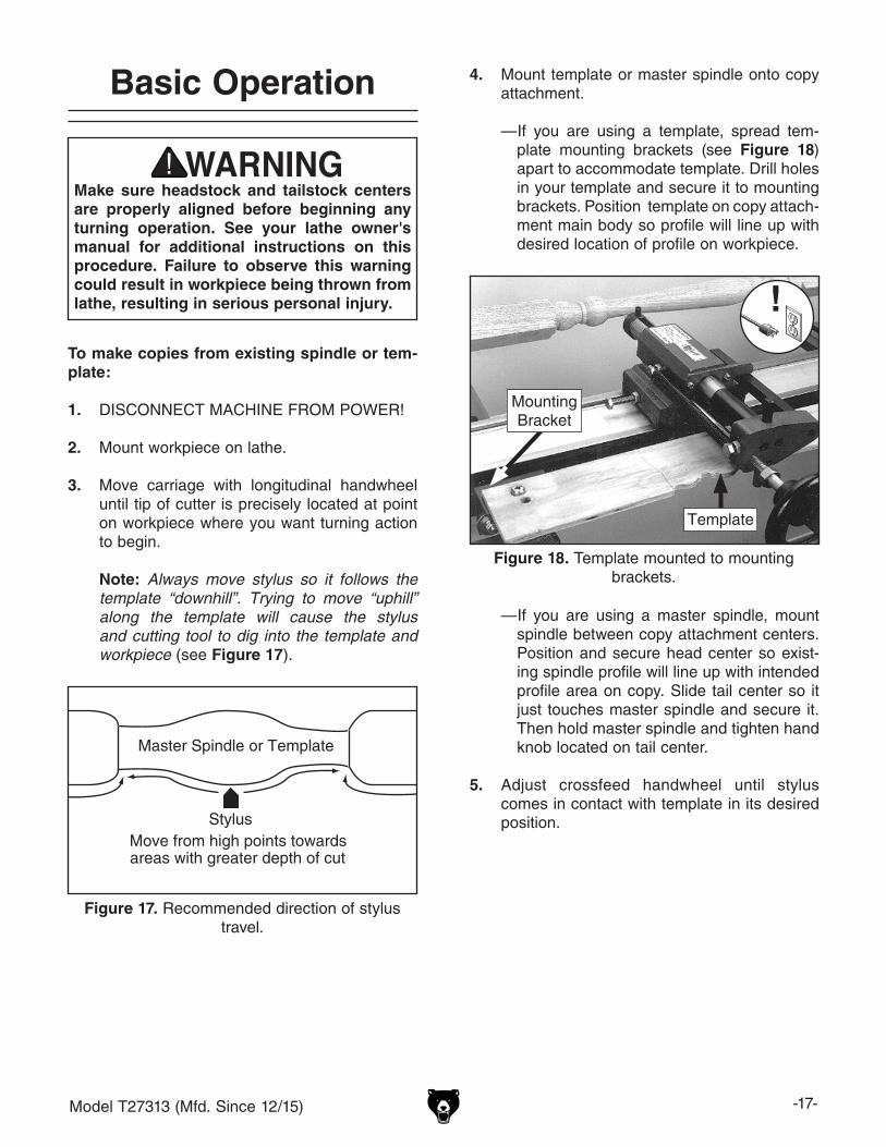
Basic Operation 4. Mount template or master spindle onto copy attachment.
—If you are using a template, spread tem-plate mounting brackets (see Figure 18) apart to accommodate template. Drill holes in your template and secure it to mounting brackets. Position template on copy attach-ment main body so profile will line up with desired location of profile on workpiece.
To make copies from existing spindle or tem-plate:
1. DISCONNECT MACHINE FROM POWER!
2. Mount workpiece on lathe.
3. Move carriage with longitudinal handwheel until tip of cutter is precisely located at point on workpiece where you want turning action to begin.
Note: Always move stylus so it follows the
template “downhill”. Trying to move “uphill” along the template will cause the stylus and cutting tool to dig into the template and workpiece (see Figure 17).
Master Spindle or Template
StylusMove from high points towardsareas with greater depth of cut
Figure 17. Recommended direction of stylus travel.
—If you are using a master spindle, mount spindle between copy attachment centers. Position and secure head center so exist-ing spindle profile will line up with intended profile area on copy. Slide tail center so it just touches master spindle and secure it. Then hold master spindle and tighten hand knob located on tail center.
5. Adjust crossfeed handwheel until stylus comes in contact with template in its desired position.
Make sure headstock and tailstock centers are properly aligned before beginning any turning operation. See your lathe owner's manual for additional instructions on this procedure. Failure to observe this warning could result in workpiece being thrown from lathe, resulting in serious personal injury.
Figure 18. Template mounted to mounting brackets.
MountingBracket
Template

-18- Model T27313 (Mfd. Since 12/15)
Figure 20. Shaping the copy spindle.
15. After completing initial copy, continue follow-ing Steps 1–14 until all spindles are com-pleted.
16. When all spindles are complete, remove copy attachment and replace it with the lathe tool post.
17. Use appropriate lathe chisels to sharpen details and smooth turned surfaces of each copy, then sand smooth.
12. Turn lathe OFF and inspect results.
—If workpiece is tapered, copy attachment is not properly aligned to wood lathe (refer to Performing Final Alignment on Page 13).
13. If you are satisfied, continue to remove mate-rial from workpiece, using “downhill” cutting method illustrated in Figure 17 on Page 17.
Tip: Avoid cutting “uphill”. It will likely result in chipping and gouging.
14. Continue removing stock until workpiece is complete (see Figure 20).
7. Repeat procedure for right hand stop.
8. Adjust cutting tool so both it and stylus are just touching workpiece and template.
—It is essential for accurate copying that cutting tool tip and stylus always remain at same positions in relation to workpiece and template.
9. Slide carriage away from workpiece, so sty-lus and cutter are clear of workpiece and template.
10. Turn lathe ON at its slowest speed, then slowly advance cutting tool toward left edge of workpiece. Once contact is made, advance cutting tool into copy spindle approximately 1⁄16". Turn longitudinal handwheel so the car-riage travels from left to right.
11. After each pass, extend cutting tool another 1⁄16" (maximum), and repeat with another pass. Repeat this process until stylus comes in contact with template.
—If cutting tool tends to bite or gouge workpiece, back off cutting tool slightly and try again. Be conservative when removing stock.
6. Move carriage stylus to left hand limit of pro-filed area and adjust left hand carriage stop until it contacts carriage, then tighten stop (see Figure 19).
Figure 19. Adjusting carriage stops.
CarriageStop
Refer to your owner's manual for complete setup, operating, and safety instructions. Serious injury could occur if you do not fol-low these instructions.

Model T27313 (Mfd. Since 12/15) -19-
SECTION 4: ACCESSORIESACCESSORIES
Installing unapproved accessories may cause machine to malfunction, resulting in serious personal injury or machine damage. To reduce this risk, only install accessories recommended for this machine by Grizzly.
NOTICERefer to our website or latest catalog for additional recommended accessories.
order online at www.grizzly.com or call 1-800-523-4777
Basic Eye ProtectionT20501—Face Shield Crown Protector 4"T20502—Face Shield Crown Protector 7"T20503—Face Shield WindowT20451—“Kirova” Clear Safety GlassesT20452—“Kirova” Anti-Reflective S. GlassesH7194—Bifocal Safety Glasses 1.5H7195—Bifocal Safety Glasses 2.0H7196—Bifocal Safety Glasses 2.5
Figure 21. Assortment of basic eye protection.
D3098—Center FinderFind the center of round or square stock for lathe turning with this handy Center Finder. One side locates a diagonal line on square stock up to 8" x 8" and the other side locates a diagonal line on round stock up to 41⁄2" in diameter.
Figure 23. D3098 Center Finder.
T20451
T20452
T20502
T20503
H7194
Recommended Metal ProtectantsG5562—SLIPIT® 1 Qt. GelG5563—SLIPIT® 12 oz. SprayG2871—Boeshield® T-9 12 oz. SprayG2870—Boeshield® T-9 4 oz. SprayH3788—G96® Gun Treatment 12 oz. SprayH3789—G96® Gun Treatment 4.5 oz. Spray
Figure 22. Recommended products for protect-ing unpainted cast iron/steel part on machinery.

-20- Model T27313 (Mfd. Since 12/15)
SECTION 5: MAINTENANCE
For optimum performance from your machine, follow this maintenance schedule and refer to any specific instructions given in this section.
Daily Check• Loose mounting bolts.• Worn or damaged wires.• Any other unsafe condition.
Monthly Check• feed cable tension, damage, or wear.• Clean/vacuum dust buildup.
Schedule
To reduce risk of shock or accidental startup, always disconnect machine from power before adjustments, maintenance, or service.
Cleaning the Model T27313 is relatively easy. Vacuum excess wood chips and sawdust, and wipe off the remaining dust with a dry cloth. If any resin has built up, use a resin dissolving cleaner to remove it.
Protect any unpainted cast iron surfaces by wip-ing it clean after every use—this ensures moisture from wood dust does not remain on bare metal surfaces. Keep cast iron surfaces rust-free with regular applications of products like G96® Gun Treatment, SLIPIT®, or Boeshield® T-9 (see Page 19 for more details).
Cleaning & Protecting
Lubrication
Leadscrews and SlidesLubrication Type ...T23964 or NLGI#2 EquivalentAmount .............................................. 1–2 PumpsLubrication Frequency .....................6–12 Months
Add lubrication to the leadscrews and slides shown in Figure 24.
Figure 24. Location of leadscrews and slides.
Leadscrews
Slides

Model T27313 (Mfd. Since 12/15) -21-
Review the troubleshooting and procedures in this section if a problem develops with your machine. If you need replacement parts or additional help with a procedure, call our Technical Support. Note: Please gather the serial number and manufacture date of your machine before calling.
SECTION 6: SERVICE
Troubleshooting
Symptom Possible Cause Possible SolutionBad surface finish. 1. Spindle speed or feed rate is wrong.
2. Dull cutting tool.3. Too much play in gibs.
1. Adjust for appropriate spindle speed and feed rate.2. Sharpen cutting tool.3. Tighten gibs (Page 1).
Cutting tool vibrates excessively during cutting.
1. Cutting tool is not tight enough. 2. Cutting tool sticks too far out of tool arbor;
lack of support. 3. Gibs are out of adjustment. 4. Cutting tool is dull.5. Spindle speed is wrong.
1. Tighten cutting tool.2. Adjust cutting tool.
3. Adjust gibs (Page 1).4. Replace or resharpen cutting tool.5. Use recommended spindle speed.
Workpiece is tapered.
1. Lathe bed and copy attachment are not parallel with each other.
2. Lathe bed is twisted.
1. Re-align lathe bed and copy attachment (Page 13).
2. Level lathe.
Carriage will not feed or is hard to move.
1. Longitudinal-feed handle screw is loose.2. Chips have loaded up on rails.
3. Slides are dry and in need of lubrication. 4. Gibs are too tight.
1. Tighten screw.2. Frequently clean away chips that load up during
turning operations.3. Lubricate slides.4. Loosen gib screw(s) slightly (Page 1).

-22- Model T27313 (Mfd. Since 12/15)
Cable Tension
The movement of the carriage assembly along the body of the copy attachment is controlled by the movement of the longitudinal-feed handwheel. This handwheel is connected to the carriage via a cable. This cable should be taut to ensure respon-sive movement from the carriage.
Tools Needed QtyOpen-End Wrench 13mm .................................. 2
To adjust cable tension:
1. DISCONNECT MACHINE FROM POWER!
2. Loosen hex nut shown in Figure 25.
3. Adjust tension by loosening or tightening cable tension bolt (see Figure 25).
Note: Cable should be pulled snug, but not so tight that stress is placed on cable.
4. Tighten hex nut (see Figure 25).
Gib Adjustment
Figure 26. Adjusting carriage gib (1 of 8).
The goal of gib adjustment is to remove sloppi-ness or "play" between the carriage and the bed while still allowing free movement of the carriage.
There are eight adjustment locations: two on the front of the carriage, two on the back and four underneath.
Tools Needed QtyHex Wrench 2.5mm ........................................... 1Open-Ended Wrench 8mm ............................... 1
To adjust gibs:
1. DISCONNECT MACHINE FROM POWER!
2. Loosen hex nut shown in Figure 26.
3. Adjust set screws to increase or decrease friction (see Figure 26).
Figure 25. Adjusting carriage cable tension.
Cable TensionBolt
4. Slide carriage back and forth to test for bind-ing or wobble.
—If carriage binds or wobbles, repeat Step 3.
5. When adjustments are complete, tighten the hex nuts while maintaining the set screw position.
Hex Nut

Model T27313 (Mfd. Since 12/15) -23-
49
50
12
3
456
54
53
9
10
11
13V2
1415
15
15
1617
18
19
2021
22
24
25V2
8 3852
28 29
30
30
3132
33
34
3536
8387
838
7
40
41
4243
44
45
46
47
47
48
Main Breakdown
SECTION 7: PARTS
Please Note: We do our best to stock replacement parts whenever possible, but we cannot guarantee that all parts shown here are available for purchase. Call (800) 523-4777 or visit our online parts store at www.grizzly.com to check for availability.

-24- Model T27313 (Mfd. Since 12/15)
Main Parts ListREF PART # DESCRIPTION REF PART # DESCRIPTION1 PT27313001 KNOB M8-1.25 29 PT27313029 PULLEY BRACKET2 PT27313002 SUPPORT ARM CLAMPING PLATE 30 PT27313030 LOCK WASHER 6MM3 PT27313003 CARRIAGE BOLT M8-1.25 X 150 31 PT27313031 LIVE CENTER4 PT27313004 SUPPORT ARM CLAMP 32 PT27313032 LIVE CENTER SLEEVE5 PT27313005 SUPPORT ARM (TALL) 33 PT27313033 EXT RETAINING RING 24MM6 PT27313006 T-BOLT M10-1.5 X 100 34 PT27313034 KNOB BOLT M12-1.75 X 907 PT27313007 FENDER WASHER 8MM 35 PT27313035 SET SCREW M5-.8 X 48 PT27313008 HEX NUT M8-1.25 36 PT27313036 PHLP HD SCR M8-1.25 X 129 PT27313009 HEX BOLT M6-1 X 25 38 PT27313038 LOCK WASHER 8MM10 PT27313010 HEX NUT M6-1 40 PT27313040 TEMPLATE SUPPORT BRACKET11 PT27313011 LONGITUDINAL FEED BRACKET 41 PT27313041 TEMPLATE SUPPORT OFFSET13V2 PT27313013V2 REAR GUIDE RAIL V2.03.16 42 PT27313042 TEMPLATE SUPPORT CLAMPING PLATE14 PT27313014 CARRIAGE STOP 43 PT27313043 HEX BOLT M8-1.25 X 6015 PT27313015 PHLP HD SCR M6-1 X 12 44 PT27313044 DEAD CENTER16 PT27313016 SET SCREW M5-.8 X 8 45 PT27313045 CENTER BRACKET17 PT27313017 HEX NUT M5-.8 46 PT27313046 CAP SCREW M6-1 X 8518 PT27313018 CARRIAGE GIB (SMALL) 47 PT27313047 CENTER CLAMPING PLATE19 PT27313019 CARRIAGE GIB (LARGE) 48 PT27313048 HEX BOLT M8-1.25 X 2520 PT27313020 HEX BOLT M6-1 X 10 49 PT27313049 SUPPORT ARM (SHORT)21 PT27313021 FLAT WASHER 6MM 50 PT27313050 T-BOLT M10-1.5 X 4522 PT27313022 CHIP GUARD 52 PT27313052 LONGITUDINAL FEED PULLEY24 PT27313024 COPY ATTACHMENT BED 53 PT27313053 HEX NUT M10-1.525V2 PT27313025V2 FRONT GUIDE RAIL V2.03.16 54 PT27313054 FENDER WASHER 10MM28 PT27313028 PULLEY SHAFT

Model T27313 (Mfd. Since 12/15) -25-
Safety labels help reduce the risk of serious injury caused by machine hazards. If any label comes off or becomes unreadable, the owner of this machine MUST replace it in the original location before resuming operations. For replacements, contact (800) 523-4777 or www.grizzly.com.
121
122123 124
125 126
127 128
129
130
131
132
133
REF PART # DESCRIPTION REF PART # DESCRIPTION121 PT27313121 EXT RETAINING RING 19MM 128 PT27313128 KEY 4 X 4 X 10122 PT27313122 LONGITUDINAL FEED PULLEY 129 PT27313129 HANDWHEEL 160MM DIA DISHED (PLASTIC)123 PT27313123 SET SCREW M8-1.25 X 16 130 PT27313130 FLAT WASHER 6MM124 PT27313124 LONGITUDINAL FEED CABLE 131 PT27313131 CAP SCREW M6-1 X 12125 PT27313125 BUSHING (COPPER) 132 PT27313132 HANDWHEEL HANDLE 126 PT27313126 LONGITUDINAL SPINDLE SLEEVE 133 PT27313133 FLAT HD SCR M6-1 X 8127 PT27313127 LONGITUDINAL FEED SPINDLE
Longitudinal Drive Breakdown

-26- Model T27313 (Mfd. Since 12/15)
231232 233 234
235 236237
238
239 240
241
242
243244
244
245246
258
247
247
248
249
250
251
252
253 254
256
255
257
Carriage Breakdown
REF PART # DESCRIPTION REF PART # DESCRIPTION231 PT27313231 SET SCREW M8-1.25 X 16 245 PT27313245 STYLUS232 PT27313232 CUTTING TOOL ARBOR 246 PT27313246 EXTENSION SPRING233 PT27313233 QUILL 247 PT27313247 HEX NUT M8-1.25 234 PT27313234 GAUGE ROD 248 PT27313248 VENTED BOLT M8-1.25 X 65235 PT27313235 INDICATOR PLATE 249 PT27313249 MOUNTING PLATE236 PT27313236 LOCK WASHER 5MM 250 PT27313250 CAP SCREW M6-1 X 12237 PT27313237 PHLP HD SCR M5-.8 X 12 251 PT27313251 HEX BOLT M8-1.25 X 16238 PT27313238 CARRIAGE SPACER 252 PT27313252 BUSHING (COPPER)239 PT27313239 LEADSCREW SEAT 253 PT27313253 CARRIAGE CASTING240 PT27313240 CAP SCREW M6-1 X 30 254 PT27313254 SET SCREW M5-.8 X 12241 PT27313241 LEADSCREW 255 PT27313255 CUTTING TOOL242 PT27313242 SET SCREW M8-1.25 X 12 256 PT27313256 HANDWHEEL 98MM DIA DISHED (PLASTIC)243 PT27313243 HANDWHEEL HANDLE 257 PT27313257 FLAT HD SCR M6-1 X 8244 PT27313244 SET SCREW M5-.8 X 10 258 PT27313258 MACHINE ID LABEL

CU
T A
LON
G D
OT
TE
D L
INE
Name _____________________________________________________________________________
Street _____________________________________________________________________________
City _______________________ State _________________________ Zip _____________________
Phone # ____________________ Email _________________________________________________
Model # ____________________ Order # _______________________ Serial # __________________
WARRANTY CARD
The following information is given on a voluntary basis. It will be used for marketing purposes to help us develop better products and services. Of course, all information is strictly confidential.
1. How did you learn about us? ____ Advertisement ____ Friend ____ Catalog ____ Card Deck ____ Website ____ Other:
2. Which of the following magazines do you subscribe to?
3. What is your annual household income? ____ $20,000-$29,000 ____ $30,000-$39,000 ____ $40,000-$49,000 ____ $50,000-$59,000 ____ $60,000-$69,000 ____ $70,000+
4. What is your age group? ____ 20-29 ____ 30-39 ____ 40-49 ____ 50-59 ____ 60-69 ____ 70+
5. How long have you been a woodworker/metalworker? ____ 0-2 Years ____ 2-8 Years ____ 8-20 Years ____20+ Years
6. How many of your machines or tools are Grizzly? ____ 0-2 ____ 3-5 ____ 6-9 ____10+
7. Do you think your machine represents a good value? _____Yes _____No
8. Would you recommend Grizzly Industrial to a friend? _____Yes _____No
9. Would you allow us to use your name as a reference for Grizzly customers in your area? Note: We never use names more than 3 times. _____Yes _____No
10. Comments: _____________________________________________________________________
_________________________________________________________________________________
_________________________________________________________________________________
_________________________________________________________________________________
____ Cabinetmaker & FDM____ Family Handyman____ Hand Loader____ Handy____ Home Shop Machinist____ Journal of Light Cont.____ Live Steam____ Model Airplane News____ Old House Journal____ Popular Mechanics
____ Popular Science____ Popular Woodworking____ Precision Shooter____ Projects in Metal____ RC Modeler____ Rifle____ Shop Notes____ Shotgun News____ Today’s Homeowner____ Wood
____ Wooden Boat____ Woodshop News____ Woodsmith____ Woodwork____ Woodworker West____ Woodworker’s Journal____ Other:

TAPE ALONG EDGES--PLEASE DO NOT STAPLE
FOLD ALONG DOTTED LINE
FOLD ALONG DOTTED LINE
GRIZZLY INDUSTRIAL, INC.P.O. BOX 2069BELLINGHAM, WA 98227-2069
PlaceStampHere
Name_______________________________
Street_______________________________
City______________State______Zip______
Send a Grizzly Catalog to a friend:

WARRANTY & RETURNSGrizzly Industrial, Inc. warrants every product it sells for a period of 1 year to the original purchaser from the date of purchase. This warranty does not apply to defects due directly or indirectly to misuse, abuse, negligence, accidents, repairs or alterations or lack of maintenance. This is Grizzly’s sole written warranty and any and all warranties that may be implied by law, including any merchantability or fitness, for any par-ticular purpose, are hereby limited to the duration of this written warranty. We do not warrant or represent that the merchandise complies with the provisions of any law or acts unless the manufacturer so warrants. In no event shall Grizzly’s liability under this warranty exceed the purchase price paid for the product and any legal actions brought against Grizzly shall be tried in the State of Washington, County of Whatcom.
We shall in no event be liable for death, injuries to persons or property or for incidental, contingent, special, or consequential damages arising from the use of our products.
To take advantage of this warranty, contact us by mail or phone and give us all the details. We will then issue you a “Return Number,’’ which must be clearly posted on the outside as well as the inside of the carton. We will not accept any item back without this number. Proof of purchase must accompany the merchandise.
The manufacturers reserve the right to change specifications at any time because they constantly strive to achieve better quality equipment. We make every effort to ensure that our products meet high quality and durability standards and we hope you never need to use this warranty.
Please feel free to write or call us if you have any questions about the machine or the manual.
Thank you again for your business and continued support. We hope to serve you again soon.
