model / series / product number jxc91
TRANSCRIPT

No.SFOD-OMT0006-A
PRODUCT NAME
EtherNet/IP Direct input type Step Motor Controller
(Servo 24VDC)
Model / Series / Product Number
JXC91

-1-
No.SFOD-OMT0006-A
Table of Contents
1. Safety Instructions ............................................... 4
2. Outlines of Product .............................................. 6
2.1 Features ..................................................................................... 6 2.2. How to Order............................................................................. 7 2.3 Product configuration ............................................................... 8 2.4 Start up procedure .................................................................... 9
(1) Checking the contents of the package ............................ 9 (2) Mounting the controller ..................................................... 9 (3) Controller Setting ............................................................... 9 (4) PLC set up ........................................................................... 9 (5) Wiring and Connection ...................................................... 9 (6) Supply of power ................................................................ 10 (7) Setting parameters ........................................................... 10 (8) Setup of the operation parameters ................................. 11 (9) Test run .............................................................................. 11
3. Specifications .................................................... 12
3.1 Specifications .......................................................................... 12 3.2 Parts Description..................................................................... 13 3.3 External Dimensions............................................................... 14
(1) Thread mounting (JXC917-□) .......................................... 14 (2) DIN rail mounting (JXC918-□).......................................... 15
3.4 Mounting .................................................................................. 16 (1) Mounting............................................................................ 16 (2) Grounding ......................................................................... 16 (3) Mounting location............................................................. 17
4. Initial Setting method ........................................ 18
4.1 Setting of switch (IP address) ................................................ 18 4.2 Hardware Configuration ......................................................... 19 4.3 Setting of EtherNet/IP
TM using
RSLogix5000
TM .................... 20
4.4 EtherNet/IP object ................................................................... 22
5. External Connections ........................................ 23
5.1 PWR: Power supply connector.............................................. 23 5.2 MOT: Motor connector, ENC: Encoder connector ............... 23 5.3 SI: Serial I/O Connector .......................................................... 23
(1) Connecting the teaching box .......................................... 23 (2) Connection with a PC ...................................................... 24
5.4 P1, P2: Communication modular........................................... 24
6. CN1: Power Supply Plug ................................... 25
6.1 Power supply plug specifications ......................................... 25 6.2 Electrical Wiring Specifications ............................................ 25 6.3 Power Supply Plug Wiring ..................................................... 26
(1) Wiring of power supply (C24V, M24V, 0V) ...................... 26 (2) Wiring of the stop switch (EMG) ..................................... 26 (3) Wiring of the lock release (LK RLS) ............................... 26
-2-
No.SFOD-OMT0006-A
6.4 Wiring of shutdown circuit ..................................................... 27 (1) Example circuit 1- Single controller with teaching box ... 27 (2) Stop (relay contact (1)) ..................................................... 28 (3) Motor power shutdown (relay contact (2)) ..................... 29
7. LED display ........................................................ 30
7.1 LED display .............................................................................. 30 7.2 LED and Controller Status ..................................................... 30
8. Operation methods ............................................ 31
8.1 Outline ...................................................................................... 31 8.2 Operation by Step No. ............................................................ 31 8.3 Positioning/speed monitor ..................................................... 31 8.4 Operation by numerical instruction ...................................... 31
9. Memory map ....................................................... 32
9.1 Memory allocation ................................................................... 32
10. Settings and Data Entry ................................... 41
10.1 Step Data ................................................................................ 41 10.2 Basic parameters .................................................................. 44 10.3 Return to origin parameter ................................................... 46
11. Operations ........................................................ 47
11.1 Return to Origin ..................................................................... 47 11.2 Positioning Operation ........................................................... 47 11.3 Pushing Operation ................................................................ 48
(1) Pushing operation is successfully performed. ............. 48 (2) Pushing operation fails (empty pushing). ..................... 48 (3) Movement of the workpiece after the completion of the pushing process ......................................................... 48
11.4 Controller input signal response time ................................ 49 11.5 Methods of interrupting operation ...................................... 49
12. Operation Examples ........................................ 50
12.1 Positioning Operation .......................................................... 50 12.2 Pushing Operation ................................................................ 51
13. Operation Instructions..................................... 52
13.1 Overview of the Operation Instructions ............................. 52 13.2 Operation procedure for Operation by Step No. ............... 52
[1] Power ON and Return to Origin position ....................... 52 [2] Positioning operation ...................................................... 53 [3] Pushing Operation ........................................................... 54 [4] HOLD .................................................................................. 54 [5] Reset .................................................................................. 55 [6] Stop .................................................................................... 55 [7] Area output ........................................................................ 56
13.3 Operation procedure for Operation by numerical instruction ...................................................................................... 57
14. Options ............................................................. 58
14.1 Actuator cable [5m or shorter] ............................................ 58 14.2 Actuator cable [8 to 20m] ..................................................... 58 14.3 Actuator cable for with lock [5m or less] ........................... 59

-3-
No.SFOD-OMT0006-A
14.4 Actuator cable for with lock [8 to 20m] ............................... 59 14.5 Controller Set up kit .............................................................. 60 14.6 Conversion Cable .................................................................. 60 14.7 Teaching box ......................................................................... 61
15. Alarm for Motor Control .................................. 62
15.1 Remote IO signal output for alarm group .......................... 62 15.2 Alarms and countermeasures ............................................. 63
16. Common Precautions for wiring and cable ... 67
17. Electric Actuators/Common Precautions ....... 68
17.1 Design and selection ............................................................ 68 17.2 Mounting ................................................................................ 69 17.3. Handling Precautions .......................................................... 70 17.4 Operating environment ........................................................ 71 17.5 Maintenance Precautions ..................................................... 72 17.6 Precautions for actuator with lock ...................................... 72
18. Controller and Peripheral Devices/Specific Product Precautions ........................................ 73 18.1 Design and selection ............................................................ 73 18.2 Handling Precautions ........................................................... 74 18.3 Mounting ................................................................................ 75 18.4 Wiring ..................................................................................... 75 18.5 Power supply ......................................................................... 76 18.6 Grounding .............................................................................. 76 18.7 Maintenance .......................................................................... 76
19. Troubleshooting ............................................... 77
20. Definitions and terminology ............................ 82
-4-
No.SFOD-OMT0006-A
JXC91/Controller 1. Safety Instructions
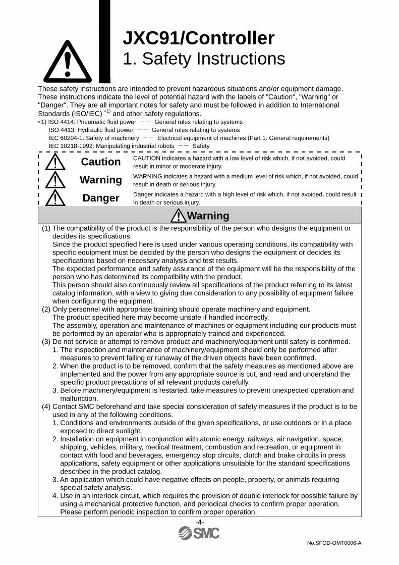
These safety instructions are intended to prevent hazardous situations and/or equipment damage. These instructions indicate the level of potential hazard with the labels of "Caution", "Warning" or "Danger". They are all important notes for safety and must be followed in addition to International
Standards (ISO/IEC) 1)
and other safety regulations. 1) ISO 4414: Pneumatic fluid power -- General rules relating to systems
ISO 4413: Hydraulic fluid power -- General rules relating to systems
IEC 60204-1: Safety of machinery -- Electrical equipment of machines (Part 1: General requirements)
IEC 10218-1992: Manipulating industrial robots -- Safety
Caution
CAUTION indicates a hazard with a low level of risk which, if not avoided, could
result in minor or moderate injury.
Warning WARNING indicates a hazard with a medium level of risk which, if not avoided, could
result in death or serious injury.
Danger
Danger indicates a hazard with a high level of risk which, if not avoided, could result
in death or serious injury.
Warning (1) The compatibility of the product is the responsibility of the person who designs the equipment or
decides its specifications. Since the product specified here is used under various operating conditions, its compatibility with specific equipment must be decided by the person who designs the equipment or decides its specifications based on necessary analysis and test results. The expected performance and safety assurance of the equipment will be the responsibility of the person who has determined its compatibility with the product. This person should also continuously review all specifications of the product referring to its latest catalog information, with a view to giving due consideration to any possibility of equipment failure when configuring the equipment.
(2) Only personnel with appropriate training should operate machinery and equipment. The product specified here may become unsafe if handled incorrectly. The assembly, operation and maintenance of machines or equipment including our products must be performed by an operator who is appropriately trained and experienced.
(3) Do not service or attempt to remove product and machinery/equipment until safety is confirmed. 1. The inspection and maintenance of machinery/equipment should only be performed after
measures to prevent falling or runaway of the driven objects have been confirmed. 2. When the product is to be removed, confirm that the safety measures as mentioned above are
implemented and the power from any appropriate source is cut, and read and understand the specific product precautions of all relevant products carefully.
3. Before machinery/equipment is restarted, take measures to prevent unexpected operation and malfunction.
(4) Contact SMC beforehand and take special consideration of safety measures if the product is to be used in any of the following conditions. 1. Conditions and environments outside of the given specifications, or use outdoors or in a place
exposed to direct sunlight. 2. Installation on equipment in conjunction with atomic energy, railways, air navigation, space,
shipping, vehicles, military, medical treatment, combustion and recreation, or equipment in contact with food and beverages, emergency stop circuits, clutch and brake circuits in press applications, safety equipment or other applications unsuitable for the standard specifications described in the product catalog.
3. An application which could have negative effects on people, property, or animals requiring special safety analysis.
4. Use in an interlock circuit, which requires the provision of double interlock for possible failure by using a mechanical protective function, and periodical checks to confirm proper operation. Please perform periodic inspection to confirm proper operation.

-5-
No.SFOD-OMT0006-A
JXC91/Controller 1. Safety Instructions
Caution The product is provided for use in manufacturing industries.
The product herein described is basically provided for peaceful use in manufacturing industries.
If considering using the product in other industries, consult SMC beforehand and provide
specifications or a contract, if necessary.
If anything is unclear, contact your nearest sales branch.
Limited Warranty and Disclaimer/
Compliance Requirements The product used is subject to the following "Limited Warranty and Disclaimer" and "Compliance
Requirements".
Read and accept them before using the product.
Limited Warranty and Disclaimer
(1) The warranty period of the product is 1 year in service or within 1.5 years after the product is
delivered. 3)
Also, the product may have specified durability, running distance or replacement parts.
Please consult your nearest sales branch.
(2) For any failure or damage reported within the warranty period, which is clearly our responsibility, a
replacement product or necessary parts will be provided.
This limited warranty applies only to our product independently, and not to any other damage
incurred due to the failure of the product.
(3) Prior to using SMC products, please read and understand the warranty terms and disclaimers
noted in the specified catalog for the particular products.
3) Vacuum pads are excluded from this 1 year warranty.
A vacuum pad is a consumable part, so it is warranted for a year after it is delivered.
Also, even within the warranty period, the wear of a product due to the use of the vacuum pad or failure due
to the deterioration of rubber material are not covered by the limited warranty.
Compliance Requirements 1. The use of SMC products with production equipment for the manufacture of weapons of mass
destruction (WMD) or any other weapon is strictly prohibited.
2. The exports of SMC products or technology from one country to another are govemed by the
relevant security laws and regulation of the countries involved in the transaction. Prior to the
shipment of a SMC product to another country, assure that all local rules goveming that export are
known and followed.

-6-
No.SFOD-OMT0006-A
2. Outlines of Product
2.1 Features
Features of the controller.
●EtherNet/IP compatible EtherNet/IP operation is avaiable by connecting with EtherNet/IP. Information can be written and read to and from it.
●Actuator control
Positioning operation and operation at a specific speed and force for the actuator are possible by controlling the Step motor (servo 24VDC).
●Specified force operation
Control the pushing force or the pressing force of the actuator.
●Separated power supply Power supply input is separated into the motor power supply and control power supply. Even if the power supply for the motor is turned OFF, the information from the encoder position is not lost while the control power supply is ON, and EtherNet/IP communication and serial communication is available.
●Return to origin
Returning to origin is possible by a signal from EtherNet/IP.
●Alarm detection function Abnormal conditions are self-detected. Alarms are output by EtherNet/IP communication and serial communication. Alarm history can be stored in the memory in the controller.
●64 points positioning/pushing are available
Control the actuator according to the specified operation pattern by DRIVE signal or manipulating the memory allocated to the input/output port such as INP signal from EtherNet/IP. It is possible to set up various parameters for each operation pattern.
●Area output
The memory corresponding to the controller Area output terminal ON EtherNet will be activated if the actuator position is within the range specified by "Area 1" and "Area 2" in the step data.
●Data input method
It is possible to perform parameter setup, status monitoring, trial run and alarm reset via EtherNet/IP communication or the serial communication with a PC installed with the controller setting software or the teaching box.
●Easy mode and Normal mode
There are two available modes for the controller setting software and the teaching box. In Easy mode, you can start the operation by only setting the speed, position, etc. In Normal mode, further detailed setup can be performed.
Caution When the device is set up or failure occurs, please refer the operation manual of the actuator and the teaching box as well as this operation manual. Keep this operation manual accessible for reference when necessary.

-7-
No.SFOD-OMT0006-A
2.2. How to Order
How to order is shown below.
Caution Single controllers are also shipped after setting the actuator specification parameters. Confirm the combination of the controller and the actuator is correct. <Check the following before use.>
•Check the actuator label for the model number. Check that this matches the controller.
Caution Refer to the chart of LECPMJ for checking the chart of <Speed - Work load> of actuator. A high peak current is required to be supplied by the comtroller when the actuator motor is turned ON. Please use a power supply with a current capacity of at least 1.5 times the peak power that is required by the actuator motor
JX C 9 1 - Electric equipment
Controller type
9 EtherNet/IPTM
Number of shaft/ Type of power supply
1 1 axis, Power supply (24VDC)
Mounting
7 Direct mounting
8 DIN rail
Actuator Model
(Enter from the actuator model to "stroke") Ex.) LEFS16B-100B-S1MJS,
input [LEFS16B-100].
Step Motor Controller

-8-
No.SFOD-OMT0006-A
•Power supply plug (Included)
<Applicable wire size>
AWG20 (0.5mm2)
PLC
Controller power supply 24VDC
•Controller set up kit
(Controller setting software,
communication cable,
conversion unit, USB cable
are included)
Part No: LEC-W2
•Communication cable
PC
•Conversion unit
•USB cable (A-miniB type)
位置 速度
100 500
200 1000
50 200
1
2
3
テスト
テスト
テスト
現在位置 120.3
現在速度 200
mm
mm/s
動作中
アラーム
モニタ
設定 位置 速度
100 500
200 1000
50 200
1
2
3
テスト
テスト
テスト
現在位置 120.3
現在速度 200
mm
mm/s
動作中
アラーム
モニタ
設定
•Conversion cable
Product no.: P5742-69
2.3 Product configuration
An example of the controller structure is shown below.
1. These items are included when ordered using the part number for an actuator set.
2. Latest version of the controller setting software must be used.
Upgrade software can be downloaded from SMC website. http://www.smcworld.com/
Warning Refer to 5. External Connections (P.23) for wiring. Refer to 16. Precautions for wiring and cable (P.67) when handling the wiring and cables. The Communication cable must be connected to a PC using a USB cable through a conversion unit. Do not connect the teaching box to a PC. Do not use LAN cable to connect to the controller, as this may cause damage to the personal computer.
1
To P1, P2
Electric actuator
To PWR
To MOT
To ENC
•Controller
•Actuator cable
(Robotic type cable)
Model number:
•LE-CP-□-□
(Robotic type cable)
•LE-CP-□-□-S
(Standard cable)
1 EtherNet/IP TM
•Teaching box
(3m cable is provided.)
Product number:
LEC-T1-3□G□
(Option)
To SI
or
2
-9-
No.SFOD-OMT0006-A
2.4 Start up procedure
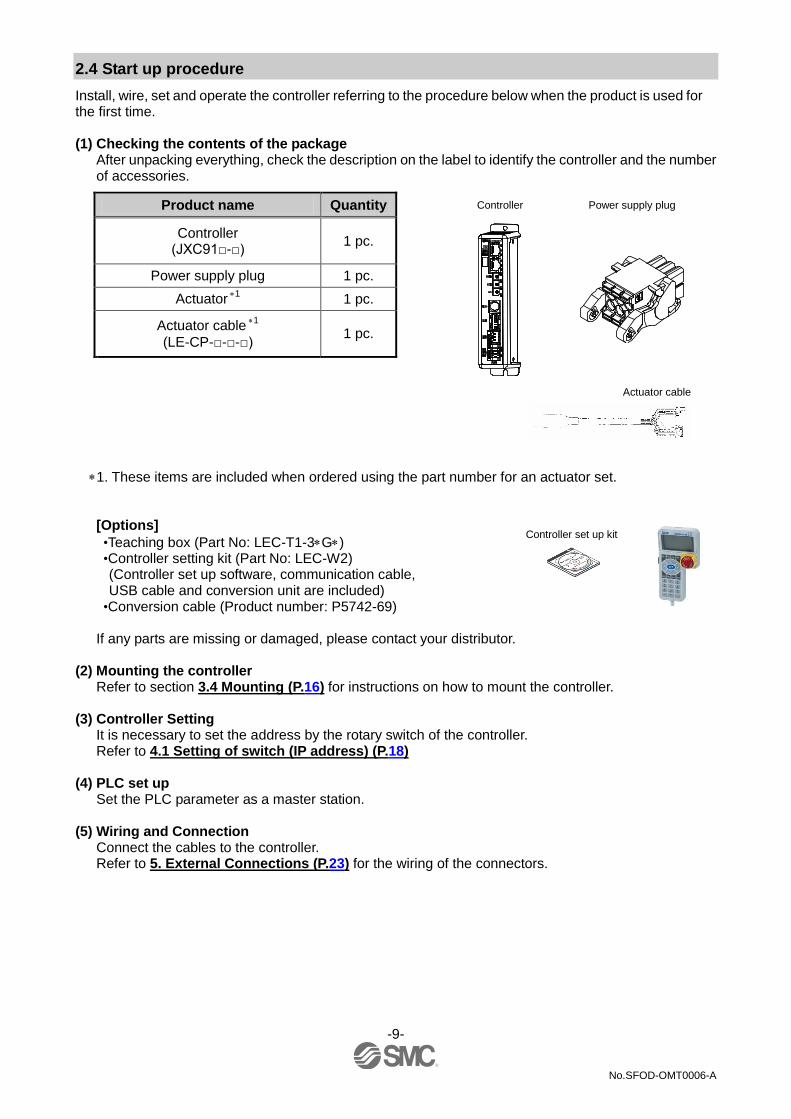
Install, wire, set and operate the controller referring to the procedure below when the product is used for the first time. (1) Checking the contents of the package
After unpacking everything, check the description on the label to identify the controller and the number of accessories.
Product name Quantity Controller Power supply plug
Controller (JXC91□-□)
1 pc.
Power supply plug 1 pc.
Actuator 1
1 pc.
Actuator cable 1
(LE-CP-□-□-□) 1 pc.
Actuator cable
1. These items are included when ordered using the part number for an actuator set.
[Options]
•Teaching box (Part No: LEC-T1-3G) •Controller setting kit (Part No: LEC-W2) (Controller set up software, communication cable, USB cable and conversion unit are included)
•Conversion cable (Product number: P5742-69)
If any parts are missing or damaged, please contact your distributor. (2) Mounting the controller
Refer to section 3.4 Mounting (P.16) for instructions on how to mount the controller. (3) Controller Setting
It is necessary to set the address by the rotary switch of the controller. Refer to 4.1 Setting of switch (IP address) (P.18)
(4) PLC set up
Set the PLC parameter as a master station. (5) Wiring and Connection
Connect the cables to the controller. Refer to 5. External Connections (P.23) for the wiring of the connectors.
Controller set up kit

-10-
No.SFOD-OMT0006-A
(6) Supply of power
Supply power 24VDC. If the condition is normal, LED on the front of the controller turns ON as the table below when power is supplied.
Items LED condition Status
PWR Green LED is ON Supply power
ALM OFF No alarm
Refer to 7. LED display (P.30) for the explanation of LED lamps. If the red [ALM] LED on the front of the controller (LEC) is ON, the alarm has been triggered.
Caution When an alarm is generated Refer to a corresponding memory of EtherNet/IP or connect a PC or teaching box to the SI serial I/O connector and check the details of the alarm. Then, remove the cause of the error referring to the 15. Alarm for Motor Control (P.62).
Please refer to the manuals of the controller setting software or the teaching box for details of the
alarms.
(7) Setting parameters
It is necessary to set the controller parameters.
The status of the LEDs on the front of the controller matches the table below when the setting of PLC and parameters complete properly and EtherNet/IP communication is established.
Items LED condition Status
PWR Green LED is ON Supply power
ALM OFF No alarm
MS Green LED is ON Operating normally
NS Green LED is ON EtherNet/IP communications established.
Refer to 7 LED display (P.30) for the explanation of LED lamps. Communication between PLC and controller is not established when LED[NS] on the front of the controller(JXC) is OFF, green LED flashes, or red LED flashes or turns ON.
Caution Communication between PLC and controller is not established. Refer to 19. Troubleshooting (P.77) Check if the communication speed of the PLC and controller and the information of the host computer are correctly set.

-11-
No.SFOD-OMT0006-A
(8) Setup of the operation parameters
Set up the operation pattern (step data, basic parameters and return to origin parameters) to specify the target position, speed, etc. by using a PC (with the controller setting software) or the teaching box.
■PC (Normal mode) ■Teaching box
Please refer to the manuals of the controller setting software or the teaching box for how to set up the
operation pattern.
(9) Test run
Refer to 9. Memory map (P.32) for the assignment of the memory.
Input signals from PLC for checking the operation. Refer to 13. Operation Instruction (P.52) for
the operation.
-12-
No.SFOD-OMT0006-A
3. Specifications
3.1 Specifications
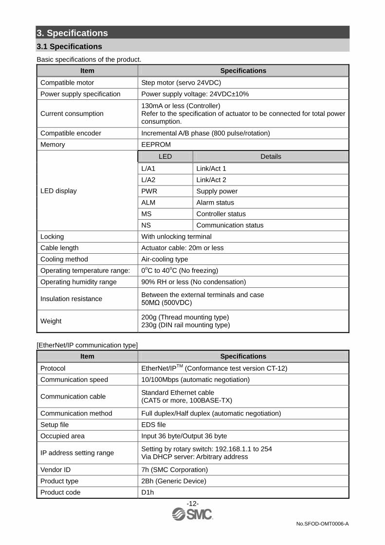
Basic specifications of the product.
Item Specifications
Compatible motor Step motor (servo 24VDC)
Power supply specification Power supply voltage: 24VDC±10%
Current consumption 130mA or less (Controller) Refer to the specification of actuator to be connected for total power consumption.
Compatible encoder Incremental A/B phase (800 pulse/rotation)
Memory EEPROM
LED display
LED Details
L/A1 Link/Act 1
L/A2 Link/Act 2
PWR Supply power
ALM Alarm status
MS Controller status
NS Communication status
Locking With unlocking terminal
Cable length Actuator cable: 20m or less
Cooling method Air-cooling type
Operating temperature range: 0oC to 40
oC (No freezing)
Operating humidity range 90% RH or less (No condensation)
Insulation resistance Between the external terminals and case 50MΩ (500VDC)
Weight 200g (Thread mounting type) 230g (DIN rail mounting type)
[EtherNet/IP communication type]
Item Specifications
Protocol EtherNet/IPTM
(Conformance test version CT-12)
Communication speed 10/100Mbps (automatic negotiation)
Communication cable Standard Ethernet cable (CAT5 or more, 100BASE-TX)
Communication method Full duplex/Half duplex (automatic negotiation)
Setup file EDS file
Occupied area Input 36 byte/Output 36 byte
IP address setting range Setting by rotary switch: 192.168.1.1 to 254 Via DHCP server: Arbitrary address
Vendor ID 7h (SMC Corporation)
Product type 2Bh (Generic Device)
Product code D1h

-13-
No.SFOD-OMT0006-A
3.2 Parts Description
Details of the parts of the controller.
No. Display Name Details
1 - Display The lamp to indicate the controller status.
2 P1, P2 EtherNet/IP communication connector
Connect Ethernet cable.
3 IP address IP address Switch to set the product EtherNet/IP communication IP address (0 to 255) by X1, X10 and X100.
4 SI Serial I/O connector (8 poles)
The connector which connect the teaching box (LEC-T1) or the setting software (LEC-W2).
5 ENC Encoder connector (16 poles)
Connect to the actuator cable.
6 MOT Motor driving connector (6 poles)
PWR Power supply connector (5 poles)
Connect to the controller power supply (24VDC) using the power supply plug. Control power (+), Stop signal (+), Motor power (+), Lock release (+), Common power (-)
8 - Applicable actuator model number label
Applicable actuator description
9 - Controller part number label
Label indicating the controller part number.
10 - MAC address EtherNet/IP MAC address is displayed.
11 - FG Connection to Frame ground (When the controller is mounted, tighten screws and connect the grounding cable)

-14-
No.SFOD-OMT0006-A
3.3 External Dimensions
The appearance of this product is as shown in the diagram below: (1) Thread mounting (JXC917-□)

-15-
No.SFOD-OMT0006-A
(2) DIN rail mounting (JXC918-□)

-16-
No.SFOD-OMT0006-A
3.4 Mounting
(1) Mounting The controller can be direct mounted using screws or mounted on a DIN rail. Details of the controller mounting options are shown below.
[1]Thread mounting (JXC917-□) [2]DIN rail mounting (JXC918-□)
(Mounting with two M4 screws) (Mounting with DIN rail)
Before locked onto DIN rail Locked onto DIN rail
(2) Grounding
Place the grounding cable with crimped terminal between the M4 screw and shakeproof washer as shown below and tighten the screw.
Caution The M4 screw, cable with crimped terminal and shakeproof washer must be prepared by the user. The controller must be connected to Ground to reduce noise.
Controller
M4 screw
Cable with crimping terminal
Shakeproof washer

-17-
No.SFOD-OMT0006-A
Caution (1) A dedicated Ground connection must be used. Grounding should be to a D-class ground
(ground resistance of 100Ω or less). (2) The cross sectional area of the grounding cable shall be 2mm
2 minimum.
The Grounding point should be as near as possible to the controller. Keep the grounding cable as short as possible.
(3) Mounting location
Design the size of the control panel and the installation type so that the temperature surrounding the controller is 40
oC or less.
Mount the controller vertically on the wall with 30mm or 50 more of space on the top and bottom of the controller as shown below. Allow 60mm or more of space between the front of the controller and the cover of the control cabinet to allow access to the connectors. Leave enough space between the controllers so that the operating temperatures of the controllers stay within the specification range. Avoid mounting the controller near a vibration source, such as a large electromagnetic contactor or circuit fuse breaker on the same panel, or keep it away from the controller.
Caution If the mounting surface for the controller is not flat or is uneven, excessive stress can be applied to the case, which can cause failure. Mount on a flat surface.
30mm or longer
30mm or more (screw mounting)
50mm or more (DIN rail mounting)
Controller
Door (Lid)
0mm or more (Actuator body size 16 or less, all size of LEH series is applicable)
10mm or more (Actuator body size 25 or more)
60mm or longer
Controller
Shared grounding --- Not acceptable
Controller
Other equipment
Dedicated grounding --- Good
Controller
Other
equipment
D-class grounding

-18-
No.SFOD-OMT0006-A
4. Initial Setting method
4.1 Setting of switch (IP address)
Turn OFF the power supply while setting the switch. The rotary switch should be set with a small watchmaker’s screwdriver.
1: Remot control
The mode to respond to the commands below of BOOTP/DHCP Server provided by Rockwell Automation.
Enable DHCP
Information including IP address can be obtained from BOOTP/DHCP Server. If the power is supplied again in this
state, the controller tries to obtain the information including IP address again.
Disable BOOTP/DHCP
Information including IP address is not obtained from BOOTP/DHCP Server. Previous setting can be held if power
is supplied under this condition.
2: Manual setting of IP address
IP address is set within the range of 192.168.1.1 to 192.168.1.254.
3: DHCP mode
Obtain IP address from DHCP Server. Obtained IP address is lost when power supply is cut.
Default setting
"Enagle DHCP" at "Remote control".
Remote Control mode If the controller IP address is unknown, change to DHCP mode and re-assign the correct IP address. When the DHCP server has assigned the correct address, turn off the power supply and return the unit to Remote control mode. Upon power-up, the JXC91 will now be available using the address that was set whilst in DHCP mode.

-19-
No.SFOD-OMT0006-A
4.2 Hardware Configuration
■EDS files and icons EDS file is required to configure the controller.Furthermore, icons are necessary for the display icon of the controller on the configurator. The EDS and icon files can be downloaded from the URL given below.
•URL:http://www.smcworld.com Informative documents → Operation manual --> jxc91_v10.zip
•Contents of jxc91_v10.zip EDS file jxc91_v10.eds
Icon xc91_1.ico

-20-
No.SFOD-OMT0006-A
4.3 Setting of EtherNet/IPTM using RSLogix5000TM
Method to connect the JXC91 to the Rockwell Automation EtherNet/IPTM
module (master) is shown below.
Refer to the Operation Manual of the RSLogix5000TM
for the detailed operation.
: This figure shows the display of Rockwell Automation software, RSLogix5000TM
.
•Select [EtherNet/IPTM
module] in [I/O Configuration] folder, then select [New Module].
•The [Select Module] screen is displayed. Select [ETHERNET-MODULE Generic Ethernet Module], then
select [Create].

-21-
No.SFOD-OMT0006-A
•[Module Properties] screen is displayed. Perform each setting.
(1) Name: Enter the required unit name.
(2) Comm Format: Select the data format of Connection Parameters.
(3) IP Address: Enter the IP address setting for the JXC91.
(4) Assembly Instance: Perform setting as shown below.
Item Decimal
Comm Format "Data-SINT"
Input 100
Output 150
Configuration 105
(5) Size: Perform setting as shown below.
Item Decimal
Comm Format "Data-SINT"
Input 36 [bytes]
Output 36 [bytes]
Configuration 0 [bytes]
(1)
(2)
(3)
(4)、(5)
-22-
No.SFOD-OMT0006-A
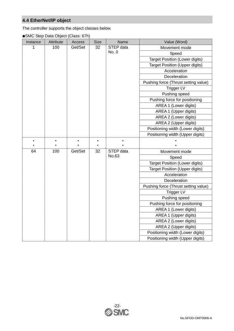
4.4 EtherNet/IP object
The controller supports the object classes below.
■SMC Step Data Object (Class: 67h)
Instance Attribute Access Size Name Value (Word)
1 100 Get/Set 32 STEP data No. 0
Movement mode
Speed
Target Position (Lower digits)
Target Position (Upper digits)
Acceleration
Deceleration
Pushing force (Thrust setting value)
Trigger LV
Pushing speed
Pushing force for positioning
AREA 1 (Lower digits)
AREA 1 (Upper digits)
AREA 2 (Lower digits)
AREA 2 (Upper digits)
Positioning width (Lower digits)
Positioning width (Upper digits)
• •
• •
• •
• •
• •
• •
64 100 Get/Set 32 STEP data No.63
Movement mode
Speed
Target Position (Lower digits)
Target Position (Upper digits)
Acceleration
Deceleration
Pushing force (Thrust setting value)
Trigger LV
Pushing speed
Pushing force for positioning
AREA 1 (Lower digits)
AREA 1 (Upper digits)
AREA 2 (Lower digits)
AREA 2 (Upper digits)
Positioning width (Lower digits)
Positioning width (Upper digits)

-23-
No.SFOD-OMT0006-A
5. External Connections
An example of standard wiring of the controller is shown for each connector.
5.1 PWR: Power supply connector
Refer to 6. CN1: Power supply plug (P.25) for wiring.
Caution Do not use an inrush current limited type of power supply for the controller.
5.2 MOT: Motor connector, ENC: Encoder connector
Connect the controller and the actuator with the actuator cable (LE-CP-)
5.3 SI: Serial I/O Connector
(1) Connecting the teaching box
Controller
Actuator cable
MOT
ENC Actuator
Motor
Controller
PWR
Controller input power supply 24VDC
(The Controller power supply (24VDC) and wires must be prepared by the user.)
Wire
Controller
SI Teaching box (3m cable is provided)
Conversion cable

-24-
No.SFOD-OMT0006-A
(PC is prepared by the user.)
Controller set up kit (Controller set up software, communication cable,
USB cable and conversion unit are included)
(2) Connection with a PC
5.4 P1, P2: Communication modular
Controller
SI
PC
Conversion unit
(Communication cable)
USB cable (A-miniB type)
位置 速度
100 500
200 1000
50 200
1
2
3
テスト
テスト
テスト
現在位置 120.3
現在速度 200
mm
mm/s
動作中
アラーム
モニタ
設定 位置 速度
100 500
200 1000
50 200
1
2
3
テスト
テスト
テスト
現在位置 120.3
現在速度 200
mm
mm/s
動作中
アラーム
モニタ
設定
P1
Specified for EtherNet/IP
Communication setting cable
PLC
(EtherNet/IP communication cable and PLC are prepared by users.)
P2
Cable can be connected to either P1 or P2. Follow the topology of EtherNet/IP communication for details.
Conversion cable

-25-
No.SFOD-OMT0006-A
6. CN1: Power Supply Plug
6.1 Power supply plug specifications
The specifications of the power supply plug supplied with the controller are shown below.
Power supply plug Terminal Function Functional explanation
0V Common power (-) The negative common power for M24V, C24V,
EMG and LK RLS.
M24V Motor power (+) The positive power for the actuator motor to be
supplied via the controller.
C24V Power supply (+) The positive control power.
EMG Stop (+) The positive power for Stop signal
LK RLS Unlocking (+) The positive power for lock release.
Equivalent to Phoenix Contact: DFMC1, 5/3-ST-LR
6.2 Electrical Wiring Specifications
Prepare the electrical wiring according to the following specifications (to be prepared by the user).
Item Specifications
Applicable wire size Single, stranded wire → AWG20 (0.5mm
2)
The rated temperature of the insulation coating should be 60oC or more.
The O.D. should be ø2.5mm or less.
Stripped wire length
Caution Do not connect multiple wires to one terminal.
After wiring the power supply plug, connect it to PWR power connector of the controller.
Refer to 6.3 Power Supply Plug Wiring (P.26) for wiring.
Controller Power supply plug inserted into CN1
8mm
0V M 24V BK RLS
ø2.5mm or less

-26-
No.SFOD-OMT0006-A
Controller Input power
supply
6.3 Power Supply Plug Wiring
Connect the power supply plug to the 24VDC controller power supply according to instructions (1) (2) and (3) and then insert it into the PWR connector of the controller. (1) Wiring of power supply (C24V, M24V, 0V)
Connect the positive of the 24VDC controller power supply to the C24V and M24V and connect the negative of that power supply to the 0V terminal.
(2) Wiring of the stop switch (EMG)
Stop switch must be installed by the user to stop the actuator in abnormal situations. Refer to 6.4 Wiring of shutdown circuit (P.27) for wiring.
(3) Wiring of the lock release (LK RLS)
Install an unlocking switch for adjustment or recovery during an emergency of the locking actuator.
Switch (24V DC, contact capacity 0.5A or more) is provided by customer. One terminal of the lock release switch should be connected to the 24VDC power supply and the other should be connected to the LK RLS terminal. When this is switched on, the lock will be released.
Caution (1) Do not use a power supply with "inrush-current control" for the controller power supply.
(2) It is unnecessary to connect LK RLS terminal when the actuator does not have locking mechanism.
(3) The LK RLS terminal is only used for adjustment and emergency return. It must not be energized during normal
operation.
Unlocking
Switch
0V
M 24V
C 24V
EMG
LK RLS
Power supply plug
External shut
down circuit
DC24V
0V
-27-
No.SFOD-OMT0006-A
Controller Input power
supply
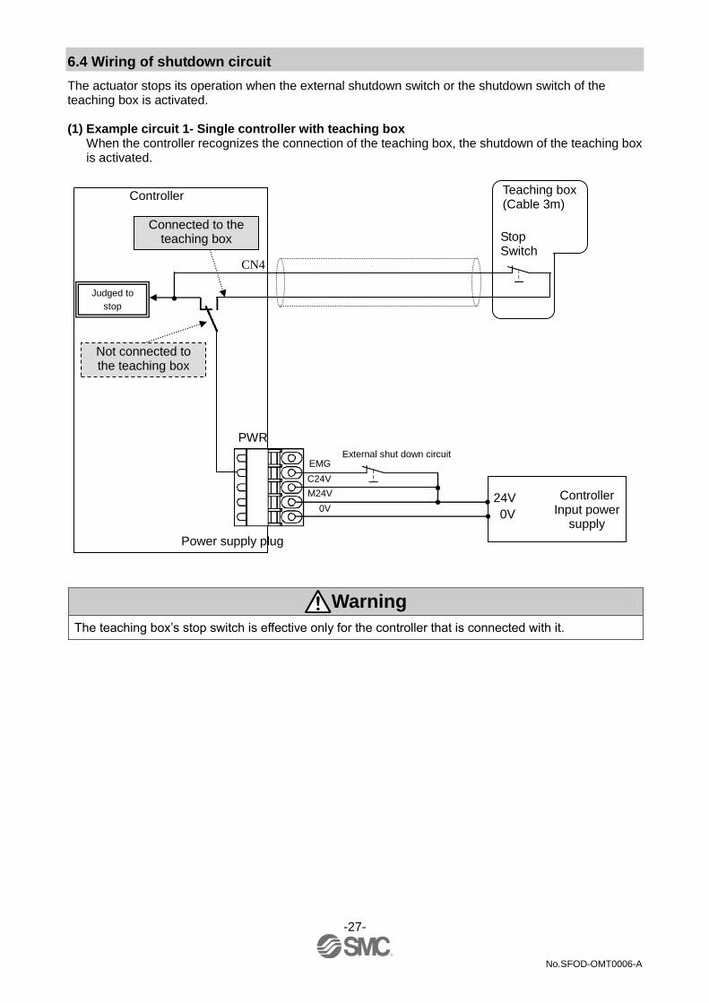
6.4 Wiring of shutdown circuit
The actuator stops its operation when the external shutdown switch or the shutdown switch of the teaching box is activated. (1) Example circuit 1- Single controller with teaching box
When the controller recognizes the connection of the teaching box, the shutdown of the teaching box is activated.
Warning The teaching box’s stop switch is effective only for the controller that is connected with it.
Judged to
stop
0V
M24V
EMG
Power supply plug
C24V
Controller
Not connected to the teaching box
Connected to the teaching box
PWR
External shut down circuit
CN4
24V
0V
Teaching box (Cable 3m)
Stop Switch
-28-
No.SFOD-OMT0006-A
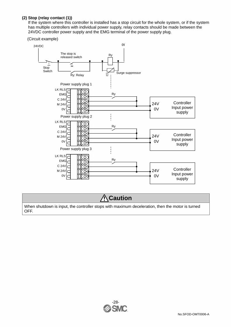
(2) Stop (relay contact (1))
If the system where this controller is installed has a stop circuit for the whole system, or if the system has multiple controllers with individual power supply, relay contacts should be made between the 24VDC controller power supply and the EMG terminal of the power supply plug.
Caution When shutdown is input, the controller stops with maximum deceleration, then the motor is turned OFF.
LK RLS
Power supply plug 1
24V
0V 0V
M 24V
C 24V
EMG Ry
Controller Input power
supply Power supply plug 2
24V
0V
Ry
Power supply plug 3
Ry
(Circuit example)
24VDC
Ry
0V
Stop Switch
Surge suppressor
The stop is released switch
Ry: Relay U
Controller Input power
supply
24V
0V
Controller Input power
supply
LK RLS
0V
M 24V
C 24V
EMG
LK RLS
0V
M 24V
C 24V
EMG

-29-
No.SFOD-OMT0006-A
Controller Input power
supply
Controller Input power
supply
Controller Input power
supply
(3) Motor power shutdown (relay contact (2))
If it is necessary to have a circuit to shutdown the motor power externally, relay contacts should be made between the 24VDC controller power supply and the M24V and EMG terminal of the power supply plug.
Warning (1) Relay contacts should be made between the 24VDC controller power supply and the M24V and
EMG terminal of the power supply plug. The actuator may make unexpected movement. (2) Do not perform return to origin (SETUP input ON) when motor drive power (M24V) is disconnected.
The controller cannot recognize the correct origin point if a return to origin instruction is made with the motor drive power (M24V) disconnected.
(3) Do not energize the LK RLS terminal while the motor drive power (M24V) is disconnected.
LK RLS
Power supply plug 1
0V
M 24V
C 24V
EMG
24V
0V
Ry
Power supply plug 2
Power supply plug 3
(Circuit example)
24VDC
Ry
0V
Stop Switch Surge suppressor
The stop is released switch
LK RLS
0V
M 24V
C 24V
EMG
24V
0V
Ry
LK RLS
0V
M 24V
C 24V
EMG
24V
0V
Ry

-30-
No.SFOD-OMT0006-A
7. LED display
7.1 LED display
Refer to the table below for the details of the LED status.
LED Details
PWR Power supply status is displayed
OFF Power is not supplied
Green LED is ON Power is supplied
ALM Condition of the controller alarm.
OFF Normal operation
Red LED is ON Alarm generated
MS Condition of the controller.
OFF The controller operating voltage is not supplied.
Green LED is ON Operating normally
Green LED is flashing Setting error
Red LED is flashing Recoverable error
Red LED is ON Unrecoverable error
NS
Display the communication status of the EtherNet/IP.
OFF The controller operating voltage is not supplied or IP address is not set.
Green LED is ON EtherNet/IP communications established.
Green LED is flashing EtherNet/IP communications not established.
Red LED is flashing EtherNet/IP connection time out
Red LED is ON IP duplicated
L/A1 Link/Act
OFF BUS IN side (P1): No Link, No Activity
Green LED is ON BUS IN side (P1): Link, No Activity
Green LED is flashing BUS IN side (P1): Link, Activity
L/A2 Link/Act
OFF BUS OUT side (P2): No Link, Activity
Green LED is ON BUS OUT side (P2): Link, No Activity
Green LED is flashing BUS OUT side (P2): Link, Activity
7.2 LED and Controller Status
Refer to the table below for the LED and the controller status.
Controller status LED description
PWR ALM MS NS
When EtherNet/IP communication is normal
- - Green LED
is ON Green LED
is ON
Motor controller
Controller alarm generated LED is OFF Red LED is
ON - -
Controller system error generated
Green LED is ON
Red LED is ON
- -
Writing controller EEPROM Green LED is flashing
- - -
-: Not indicated by LED
Caution Do not turn OFF the input power supply for the controller or disconnect and connect the cable while the data is being written to EEPROM (PWR LED (green) is flahing).
Possibility of incorrect / corrupted data (step data, parameter)
0V M 24V BK RLS

-31-
No.SFOD-OMT0006-A
8. Operation methods
8.1 Outline
Two types of operation method are available for this product. The first method is "Operation by Step No.". When using this method, step data stored in the product can be driven by sending specific commands over the network. The second method is "Operation by numerical instruction". When using this method the numerical data (ex. Position, speed, acceleration etc.) is sent directly over the network.
8.2 Operation by Step No.
The function of this mode is to read/write the memory bits corresponding to the input/output port signals (ex. DRIVE, INP) over EtherNet/IP from an upper level device. When an operation is based on the preset step data, select the step data No. by activating the correct Input bits (IN0, IN1 etc.) then activate the DRIVE signal. Refer to 13.2 Operation procedure for Operation by Step No. (P.52).
8.3 Position/speed monitor
Reads the current position and current speed.
8.4 Operation by numerical instruction
When numerical data relating to the actuator speed, position etc. is sent, the actuator will execute this data provided it is within the allowable range of values. The range of values for each mode are shown below. Preparatory operations such as turning the servo on and performing a return to origin are required before the actuator may execute step data or numerical data.
Refer to 13.3 Operation procedure for operation by numerical instruction (P.57).
0V M 24V BK RLS

-32-
No.SFOD-OMT0006-A
9. Memory map
9.1 Memory allocation
9.1.1 Input Area Mapping •Input area mapping of upper level device
Offset (Word)
Input data
0 Input port to which signals are allocated
1 Controller information flag
2 Current position (Lower digits)
3 Current position (Upper digits)
4 Current speed
5 Current pushing force
6 Target Position (Lower digits)
7 Target Position (Upper digits)
8 Alarm 1, 2
9 Alarm 3, 4
10 Reserve
11 Reserve
12 Reserve
13 Reserve
14 Reserve
15 Reserve
16 Reserve
17 Reserve
0V M 24V BK RLS

-33-
No.SFOD-OMT0006-A
•Input area mapping of upper level device Word0: Signals allocated to the input port
Word Bit Signal name Description
0
0 OUT0 When the operation is started and DRIVE is turned OFF, a Bit no. corresponding to the number of the active step data will be output from these signals. This output signal will be updated when DRIVE (A11) signal is turned ON.
Ex. (Step data No.3 is output)
OUT5 OUT 4 OUT 3 OUT 2 OUT 1 OUT 0
OFF OFF OFF OFF ON ON
Caution (1) When RESET is turned ON, these signals are turned OFF.
(2) During the alarm, these signals output the alarm group.
(3) During the pushing operation, if the actuator runs over
the defined pushing width, these signals will be turned
OFF.
1 OUT1
2 OUT2
3 OUT3
4 OUT4
5 OUT5
6 - -
7 - -
8 BUSY
This signal is ON during the movement of the actuator (during the positioning operation, etc.).
Caution During the pushing operation without movement (no
movement but the actuator generating the pushing force).
9 SVRE When the servo motor is OFF, SVRE is OFF. When the servo motor is ON, SVRE is ON.
10 SETON When the actuator is in the SETON status (the position information is established), this signal is turned ON. When the position status is not established, this signal is OFF.

-34-
No.SFOD-OMT0006-A
Word Bit Signal name Description
0
11 INP
The condition when the INP output is ON depends on the actuator action.
•Return to origin
Turns ON at the origin when within the ±"default Imposition"
in the Basic parameter. •During positioning operation Turns ON when the current position is within "Step data position ± positioning range".
•During pushing operation Turns ON when the pushing force exceeds the value set in the step data "Trigger LV".
Caution After the pushing operation is completed, even if it switches
automatically to energy saving mode, the INP output signal
stays ON.
When movement starts again from the pushing stopped state,
pushing operation is repeated with the normal pushing force.
Ex) Step data "force" is 100%
Step data "Trigger LV" is 80%,
The energy saving setting of the actuator is 40%.(1)
1 The actuator model determines the energy settings.
Please refer to the manual of the actuator for more details.
12 AREA When the actuator is within the output range between Area1
and Area2 in the step data, this signal will be turned ON. The range changes depending on the active step data.
13 WAREA
When the actuator is within the output range between "W
area output signal 1 and W area output signal 2" of basic
parameter, this signal will be turned ON.
14 ESTOP
During activation of Teaching Box stop switch, this signal is
ON. During the normal operation, this is OFF. This is
synchronized to the input signal for the EMG signal on the
controller connector CN1.
15 ALARM
Alarm generated when problems occur to the actuator or its
controlling status. OFF when there are no alarms.
ON in alarm condition.
Energy saving mode
Time
Trigger LV
INP (ON)
100
80
40
Pushing force
(%)
-35-
No.SFOD-OMT0006-A
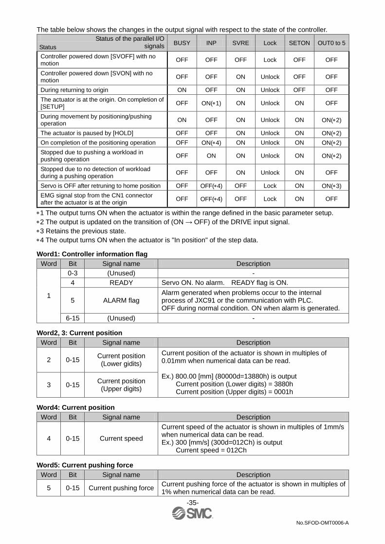
The table below shows the changes in the output signal with respect to the state of the controller.
BUSY INP SVRE Lock SETON OUT0 to 5
Controller powered down [SVOFF] with no motion
OFF OFF OFF Lock OFF OFF
Controller powered down [SVON] with no motion
OFF OFF ON Unlock OFF OFF
During returning to origin ON OFF ON Unlock OFF OFF
The actuator is at the origin. On completion of [SETUP]
OFF ON(1) ON Unlock ON OFF
During movement by positioning/pushing operation
ON OFF ON Unlock ON ON(2)
The actuator is paused by [HOLD] OFF OFF ON Unlock ON ON(2)
On completion of the positioning operation OFF ON(4) ON Unlock ON ON(2)
Stopped due to pushing a workload in pushing operation
OFF ON ON Unlock ON ON(2)
Stopped due to no detection of workload during a pushing operation
OFF OFF ON Unlock ON OFF
Servo is OFF after retruning to home position OFF OFF(4) OFF Lock ON ON(3)
EMG signal stop from the CN1 connector after the actuator is at the origin
OFF OFF(4) OFF Lock ON OFF
1 The output turns ON when the actuator is within the range defined in the basic parameter setup.
2 The output is updated on the transition of (ON → OFF) of the DRIVE input signal.
3 Retains the previous state.
4 The output turns ON when the actuator is "In position" of the step data.
Word1: Controller information flag
Word Bit Signal name Description
1
0-3 (Unused) -
4 READY Servo ON. No alarm. READY flag is ON.
5 ALARM flag Alarm generated when problems occur to the internal process of JXC91 or the communication with PLC. OFF during normal condition. ON when alarm is generated.
6-15 (Unused) -
Word2, 3: Current position
Word Bit Signal name Description
2 0-15 Current position (Lower gidits)
Current position of the actuator is shown in multiples of 0.01mm when numerical data can be read. Ex.) 800.00 [mm] (80000d=13880h) is output
Current position (Lower digits) = 3880h Current position (Upper digits) = 0001h
3 0-15 Current position (Upper digits)
Word4: Current position
Word Bit Signal name Description
4 0-15 Current speed
Current speed of the actuator is shown in multiples of 1mm/s when numerical data can be read. Ex.) 300 [mm/s] (300d=012Ch) is output
Current speed = 012Ch
Word5: Current pushing force
Word Bit Signal name Description
5 0-15 Current pushing force Current pushing force of the actuator is shown in multiples of 1% when numerical data can be read.
Status of the parallel I/O signals Status
-36-
No.SFOD-OMT0006-A
Word6, 7: Target position
Word Bit Signal name Description
6 0-15 Target Position (Lower digits) Target position of the actuator is shown in multiples of
0.01mm when numerical data can be read. 7 0-15
Target Position (Upper digits)
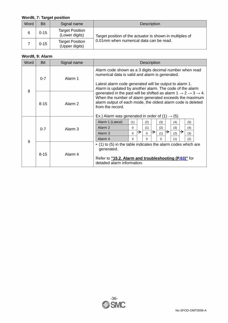
Word8, 9: Alarm
Word Bit Signal name Description
8
0-7 Alarm 1
Alarm code shown as a 3 digits decimal number when read numerical data is valid and alarm is generated. Latest alarm code generated will be output to alarm 1. Alarm is updated by another alarm. The code of the alarm generated in the past will be shifted as alarm 1 → 2 → 3 → 4. When the number of alarm generated exceeds the maximum alarm output of each mode, the oldest alarm code is deleted from the record. Ex.) Alarm was generated in order of (1) → (5)
Alarm 1 (Latest) (1) (2) (3) (4) (5)
Alarm 2 0 (1) (2) (3) (4)
Alarm 3 0 0 (1) (2) (3)
Alarm 4 0 0 0 (1) (2)
(1) to (5) in the table indicates the alarm codes which are generated.
Refer to "15.2. Alarm and troubleshooting (P.63)" for detailed alarm information.
8-15 Alarm 2
9
0-7 Alarm 3
8-15 Alarm 4

-37-
No.SFOD-OMT0006-A
9.1.2 Output area mapping •From controller to upper devices
Offset (Word)
Output data
0 Output port to which signals are allocated
1 Controlling of the controller/numerical data flag
2 Operation method/start flag
3 Speed
4 Target Position (Lower digits)
5 Target Position (Upper digits)
6 Acceleration
7 Deceleration
8 Pushing force (Thrust setting value)
9 Trigger LV
10 Pushing speed
11 Pushing force for positioning
12 AREA 1
13
14 AREA 2
15
16 Positioning width
17
•From controller to upper devices (details) Word0: Output port to which signal is allocated
Word Bit Signal name Description
0
0 IN0 The combination of high/low status of IN0 to IN5 (Bit No.) will determine the step data number. Ex.) Step data No.3 has been assigned
IN5 IN4 IN3 IN2 IN1 IN0
OFF OFF OFF OFF ON ON
1 IN1
2 IN2
3 IN3
4 IN4
5 IN5
6 - Normally, leave it OFF
7 - Normally, leave it OFF

-38-
No.SFOD-OMT0006-A
Word Bit Signal name Description
0
8 HOLD
If HOLD input is ON during operation, the speed decreases at maximum deceleration of the basic parameter until the actuator stops. The remaining stroke will be on hold as long as HOLD is ON and when HOLD is turned OFF, the actuator restarts to travel the remaining stroke. •When DRIVE or SETUP is ON
Caution (1) As long as HOLD is ON, the DRIVE input will be
disabled. (2) The output signals are rendered invalid whilst hold is in
operation.
9 SVON
The SVON signal turns the servo motor ON. When SVON is ON, the servo motor will be turned ON. When this is OFF, the servo motor will be turned OFF.
Caution (1) When SVON is ON, the actuator may move 2 to 3mm to
improve the controlling accuracy. (2) When SVON is OFF, turn OFF the DRIVE and SETUP.
10 DRIVE
When DRIVE is turned ON, the system scans the input IN0 to IN5 and starts the operation of the actuator. Then, when this signal is turned OFF, the number of the active step data will be output via the signals OUT0 to OUT5.
11 RESET
The signal to reset the alarm and the operation. After RESET, the speed decreases at maximum deceleration of the basic parameter until the actuator stops. INP and OUT0 to OUT5 will be turned OFF (however, if the actuator is stopped within the in-position range, the INP will be turned ON).
12 SETUP
When SVRE (B11) is ON, the SETUP operation (return to origin operation) will be performed. During the SETUP operation, BUSY (B7) will be turned ON and after completion of the SETUP operation, SETON (B9) and INP (B10) will be turned ON.
13 JOG(-)
Jogging to (-) direction. Moves during the signal is ON. Stops during the signal is OFF. When FLGTH (signal for switching Jogging and Inching) is ON, movement towards (-) side is made at the time of "JOG(-)" signal. INP output, OUT0 to 5 are OFF after Jogging/Inching started. INP output, OUT0 to 5 are not turned ON after Jogging/Inching completes.
14 JOG(+) Operation is the same as JPG(-). "-" is changed to "+"
15 FLGTH
Switches the function (Jogging and Inching) of Jogging signal "JOG(-)" and "JOG(+)". Inching starts when this signal is ON and when the Jogging signal is ON. Jogging starts when this signal is OFF. Inching amount is set by operation parameter.
On hold
Restart
DRIVE or
SETUP
HOLD
Speed
ON
OFF
ON
OFF
-39-
No.SFOD-OMT0006-A
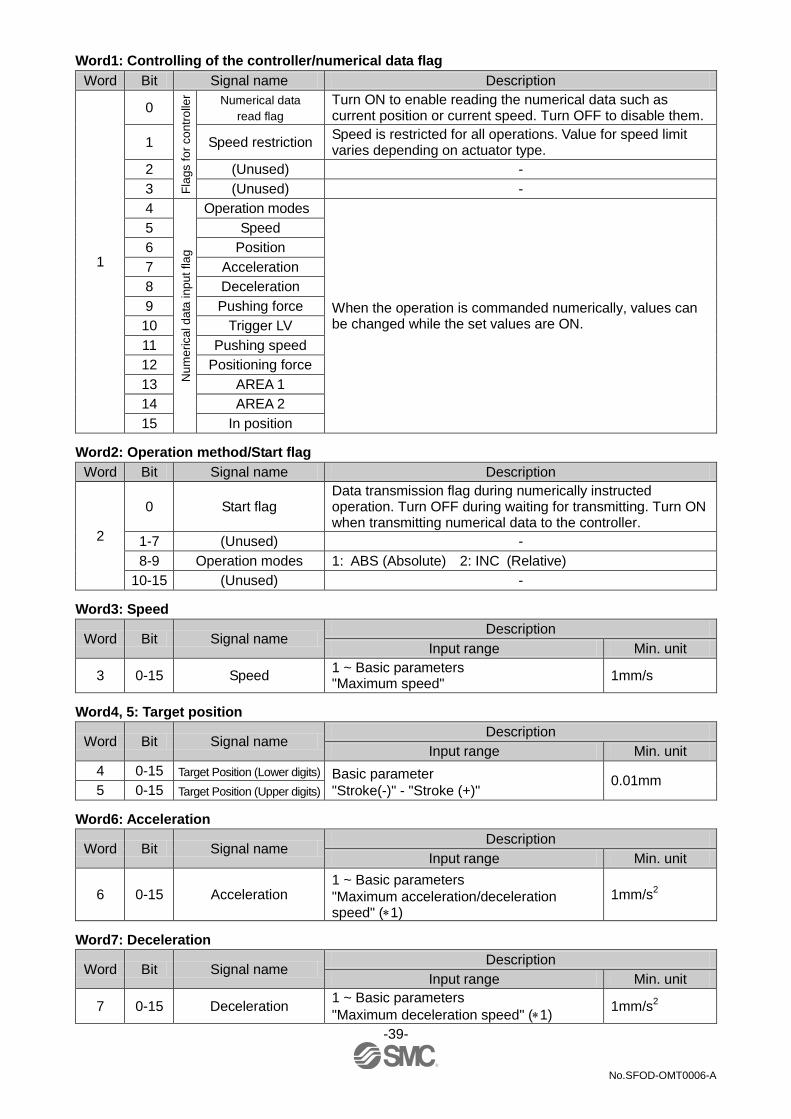
Word1: Controlling of the controller/numerical data flag
Word Bit Signal name Description
1
0
Fla
gs f
or
co
ntr
olle
r Numerical data
read flag
Turn ON to enable reading the numerical data such as current position or current speed. Turn OFF to disable them.
1 Speed restriction Speed is restricted for all operations. Value for speed limit varies depending on actuator type.
2 (Unused) -
3 (Unused) -
4
Nu
me
rica
l d
ata
inp
ut
fla
g
Operation modes
When the operation is commanded numerically, values can be changed while the set values are ON.
5 Speed
6 Position
7 Acceleration
8 Deceleration
9 Pushing force
10 Trigger LV
11 Pushing speed
12 Positioning force
13 AREA 1
14 AREA 2
15 In position
Word2: Operation method/Start flag
Word Bit Signal name Description
2
0 Start flag Data transmission flag during numerically instructed operation. Turn OFF during waiting for transmitting. Turn ON when transmitting numerical data to the controller.
1-7 (Unused) -
8-9 Operation modes 1: ABS (Absolute) 2: INC (Relative)
10-15 (Unused) -
Word3: Speed
Word Bit Signal name Description
Input range Min. unit
3 0-15 Speed 1 ~ Basic parameters "Maximum speed"
1mm/s
Word4, 5: Target position
Word Bit Signal name Description
Input range Min. unit
4 0-15 Target Position (Lower digits) Basic parameter
"Stroke(-)" - "Stroke (+)" 0.01mm
5 0-15 Target Position (Upper digits)
Word6: Acceleration
Word Bit Signal name Description
Input range Min. unit
6 0-15 Acceleration 1 ~ Basic parameters
"Maximum acceleration/deceleration speed" (1)
1mm/s2
Word7: Deceleration
Word Bit Signal name Description
Input range Min. unit
7 0-15 Deceleration 1 ~ Basic parameters
"Maximum deceleration speed" (1) 1mm/s
2

-40-
No.SFOD-OMT0006-A
Word8: Pushing force
Word Bit Signal name Description
Input range Min. unit
8 0-15 Pushing force
(Thrust setting value) (1) 1%
Word9: Trigger LV
Word Bit Signal name Description
Input range Min. unit
9 0-15. Trigger LV (1) 1%
Word10: Pushing speed
Word Bit Signal name Description
Input range Min. unit
10 0-15 Pushing speed (1) 1mm/s
Word 11: Pushing force for positioning
Word Bit Signal name Description
Input range Min. unit
11 0-15 Pushing force for
positioning (1) 1%
Word12, 13: AREA 1
Word Bit Signal name Description
Input range Min. unit
12 0-15 AREA 1 (Lower digits) Basic parameter
"Stroke (-)" - "Stroke (+)" 0.01mm
13 0-15 AREA 1 (Upper digits)
Word14, 15: AREA 2
Word Bit Signal name Description
Input range Min. unit
14 0-15 AREA 2 (Lower digits) Basic parameter
"Stroke (-)" - "Stroke (+)" 0.01mm
15 0-15 AREA 2 (Upper digits)
Word16, 17: Positioning width
Word Bit Signal name Description
Input range Min. unit
16 0-15 Positioning width
(Lower digits) (1) 0.01mm
17 0-15 Positioning width
(Upper digits)
1 The actuator model determines the limit for the input values. Please refer to the manual of the actuator for more details.

-41-
No.SFOD-OMT0006-A
10. Settings and Data Entry
In order to move the actuator to a specific position, it is necessary to setup the patterns of operations with a PC (with the controller setting software) or the teaching box. This setup data input by the software or teaching box will be recorded in the memory of the controller. For the controller setting software and the teaching box, there are two available modes (the Easy mode and the Normal mode). You can select the appropriate one depending on the operation.
•Easy mode
In Easy mode, you can start up the actuator by entering only a limited number of settings with the
controller setting software and the teaching box.
The combination of settings you need to set up will change depending on the type of actuator.
(A combination of data can be selected.)
•Normal mode
In Normal mode, you can make a further detailed setup (conditions for actuator and controller, etc.)
than the Easy mode.
You can change three kinds of setting data, "Step data", "Basic parameter" and "Return to origin
parameter" in this mode.
10.1 Step Data
A "step data" is the setting data mainly describing the movement of the actuator. Total 64 step data (12 attributes per step) can be handled with this controller. Each step data will become effective as soon as it is recorded into the controller. Ex.) Step data on the PC (controller setting software) screen [Normal mode]
No. Movement
mode
Speed
mm/s
Position
mm
Acceleration
mm/s2
Deceleration mm/s
2
Pushing
force
%
Threshold
Force
Value
%
Pushing
speed
mm/s
Moving
force
%
Area 1
mm
Area 2
mm
In pos
mm
0 Absolute 100 20.00 1000 1000 0 0 0 100 18.00 22.50 0.5
1 Absolute 50 10.00 1000 1000 70 60 5 100 6.0 12.0 1.5
┆ ┆ ┆ ┆ ┆ ┆ ┆ ┆ ┆ ┆ ┆ ┆ ┆
63 Absolute 20 5.00 500 500 0 0 0 100 3.0 8.0 1.2

-42-
No.SFOD-OMT0006-A
Step Data details
Description
Range Explanation Controller
setting
software
Teaching
box
(TB)
No. Step No. 0 to 63 Number of the step data.
Movement mode
Movement mode
3 types
(Refer to the
table on the
right)
Specifies the co-ordinate system for the target position.
Software TB PLC Details
Blank Disable 0 The step data is ineffective.
Absolute Absolute 1 The target position will be defined in
relation to the absolute origin point.
Relative Relative 2 The target position will be defined
relative to the current position.
Speed Speed 1 The speed to move to the target position. (Unit: mm/s)
Position Position
Basic parameter
"Stroke (-)" -
"Stroke (+)"
The target position (unit: mm)
Acceleration Acceleration
1 ~ Basic
parameters
"Maximum
acceleration/
deceleration
speed"
Sets the acceleration to reach to travel speed. (Unit: mm/s2)
Deceleration Deceleration
1 ~ Basic
parameters
"Maximum
acceleration/
deceleration
speed"
Sets the deceleration from travel speed to stop. (Unit: mm/s2)
Pushing force
Pushing force 1
The setting to define the pushing operation or the positioning
operation.
For the positioning operation, the value specifies the force as a
percentage of the maximum force (Unit: %).
The maximum force depends on the actuator. Please refer to the
manual and the rated force of the actuator.
Value Movement
mode Details
0 Positioning
operation
The actuator moves to the position
specified in the "Position".
1 to 100 Pushing
operation
The actuator moves to the position
specified in the "Position" and then,
performs a pushing action with a force
not more than the set force.
Trigger LV Trigger LV 1
■Effective only for the pushing operation
(when the value for the "Pushing force" is from 1 to 100).
This is the setting to define the conditions where the INP output will
be turned ON. When the actuator generates a force over this value,
INP will be turned ON.
This parameter is set to the value of the pushing force or lower.
(Unit: %)
For the positioning operation, this value is ignored.

-43-
No.SFOD-OMT0006-A
Pushing
speed
Pushing
speed 1
■Effective only for the pushing operation
(when the value for the "Pushing force" is from 1 to 100).
This defines the movement speed during the pushing operation. If
this Speed is too high, it may cause damage to the actuator or work
piece due to impacts. Therefore, enter a value within the range
appropriate for the actuator. (Unit: mm/s)
Please refer to the actuator manual for the appropriate range of the
speed.
For the positioning operation, this value is ignored.
Moving
force
Moving
force 1
The setting to define the maximum torque during the positioning
operation. (Unit: %)
Enter a value within the range appropriate for the actuator.
(Unit: mm/s)
Please refer to the actuator manual for the appropriate range of the
speed.
Area 1 AREA 1
Basic parameter
"Stroke (-)" -
"Stroke (+)"
The setting to define the conditions where the AREA output will be
turned ON (Unit: mm)
If the current position is within the range between the Area1 and
Area2, the AREA output will be turned ON.
If Area1 >Area2, the alarm "Step Data ALM1" will be activated.
(However, no alarm is generated if "Area1"= "Area2"= 0, the AREA
output will be turned OFF)
Area 2 AREA 2
Basic parameter
"Stroke (-)" -
"Stroke (+)"
In position In position 1
The functions of this will be different between the pushing operation
and the positioning operation.
Positioning operation: Positioning range (Unit: mm)
Pushing operation: Pushing distance (Unit: mm)
Movement
mode Details
Positioning
operation
This is the setting to define the conditions where
the INP output will be turned ON.
When the actuator enters within this range from
the target position, the INP will be turned ON.
(It is unnecessary to change this from the initial
value.)
If it is required to get a signal before the actuator
completes the positioning operation, this value
should be larger.
The INP output will be turned ON.
Target position - in position ≤ actuator position
≤ target position + in position
Pushing
operation
This is the setting to define the distance pushed by
the actuator during the pushing operation. When
the actuator pushed exceeding this distance, the
pushing operation will end. In case of such stop
exceeding the pushing distance, the INP will not be
turned ON.
1 The range varies depending on the actuator. Please refer to the manual of the actuator for more details.

-44-
No.SFOD-OMT0006-A
10.2 Basic parameters
The "Basic parameter" is the data to define the operating conditions of the controller, conditions of the actuator, etc.
Details of basic parameters
Activation: "■" = Effective as soon as it is recorded into the controller "○" = Become effective after restarting the controller
"-" = The parameter cannot be changed (fixed value)
Description
Range Explanation Write Controller
configuration
software
Teaching
box
Controller ID Controller ID 1 to 32 Identification number (axis) parameters of serial
communications are set. ○
IO pattern IO pattern Fixed value
This is the fixed value for this controller.
( Do not change the setting)
The value for this should be 64 (Standard).
-
Acceleration
/deceleration
pattern
Acceleration
/deceleration
pattern
Fixed value
This is the fixed value for this controller.
( Do not change the setting)
This defines the trapezoidal acceleration/deceleration parameter.
-
S-motion
rate
S-motion
rate Fixed value
This is the fixed value for this controller.
( Do not change the setting) -
Stroke (+) Stroke (+) 1
This defines the positive (+) side limit of the position. (Unit: mm)
Any value greater than the [stroke(+)] value cannot be entered in
the "Position" field data of step parameter setup.
■
Stroke (-) Stroke (-) 1
This defines the positive (+) side limit of the position. (Unit: mm)
Any value less than the [stroke(-)] value cannot be entered in the
"Position" field data of step parameter setup.
■
Maximum
velocity
Maximum
velocity 1
This defines the maximum limit of the speed. (Unit: mm/s)
Any value greater than the [Max speed] value cannot be entered
in the "Speed" field data of step parameter setup.
■
Maximum
acceleration
speed
Maximum
acceleration
/Deceleration
speed
1
This defines the maximum limit of the ACC/DEC. (Unit: mm/s2)
Any value greater than the [Max ACC/DEC] value cannot be
entered in the "Accel" field data of step parameter setup.
■
Default In
position
Default In
positioning 1
This defines the range to activate the INP output when the
actuator is within it after the return to origin operation. (Unit: mm) ■
ORIG offset ORIG offset 1
This defines the position of the actuator after the return to
origin operation. (Unit: mm)
■The ORIG offset is 0 (mm).
■The ORIG offset is 100 (mm).
Caution
If the value for the "ORIG offset" is changed, the "Stroke
(+)" and "Stroke (-)" of the basic parameters should be
checked.
■
Maximum
pushing force
Maximum
pushing force 1 The maximum force for the pushing operation. (Unit %) ■
M
In the examples on the
left, the actuator positions
are not different but the
reference point that the
controller recognizes will
be changed after the
return to origin operation.
The position is identified by the controller after
the return to the origin operation (0mm).
Actuator
M Actuator
The position is identified by the controller after
the return to the origin operation (100mm).
-45-
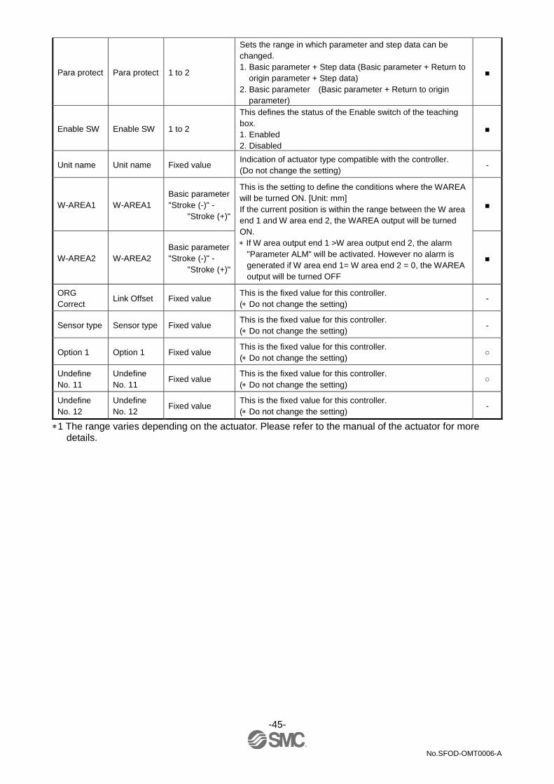
No.SFOD-OMT0006-A
Para protect Para protect 1 to 2
Sets the range in which parameter and step data can be
changed.
1. Basic parameter + Step data (Basic parameter + Return to
origin parameter + Step data)
2. Basic parameter (Basic parameter + Return to origin
parameter)
■
Enable SW Enable SW 1 to 2
This defines the status of the Enable switch of the teaching
box.
1. Enabled
2. Disabled
■
Unit name Unit name Fixed value Indication of actuator type compatible with the controller.
(Do not change the setting) -
W-AREA1 W-AREA1
Basic parameter
"Stroke (-)" -
"Stroke (+)"
This is the setting to define the conditions where the WAREA
will be turned ON. [Unit: mm]
If the current position is within the range between the W area
end 1 and W area end 2, the WAREA output will be turned
ON.
If W area output end 1 >W area output end 2, the alarm
"Parameter ALM" will be activated. However no alarm is
generated if W area end 1= W area end 2 = 0, the WAREA
output will be turned OFF
■
W-AREA2 W-AREA2
Basic parameter
"Stroke (-)" -
"Stroke (+)"
■
ORG
Correct Link Offset Fixed value
This is the fixed value for this controller.
( Do not change the setting) -
Sensor type Sensor type Fixed value This is the fixed value for this controller.
( Do not change the setting) -
Option 1 Option 1 Fixed value This is the fixed value for this controller.
( Do not change the setting) ○
Undefine
No. 11
Undefine
No. 11 Fixed value
This is the fixed value for this controller.
( Do not change the setting) ○
Undefine
No. 12
Undefine
No. 12 Fixed value
This is the fixed value for this controller.
( Do not change the setting) -
1 The range varies depending on the actuator. Please refer to the manual of the actuator for more details.

-46-
No.SFOD-OMT0006-A
10.3 Return to origin parameter
The "Return to origin parameter" is the setting data for the return to origin operation. Details of Return to origin parameter
Activation: "■" = Effective as soon as it is recorded into the controller "O" = Become effective after restarting the controller "-" = The parameter cannot be changed (fixed value)
Description
Range Explanation Write Controller
configuration
software
Teaching
box
ORIG
direction
ORIG
direction 1 to 2
Sets the direction of return to origin operation.
1. CW
2. CCW
○
ORIG mode Return to
origin mode 1 to 2
The setting for the return to origin operation.
1. Pushing origin operation [Stop]
2. Limit switch origin [Sensor]
■
ORIG limit ORIG limit 1 A pushing force level at which to set the origin. ■
ORIG time ORIG time Fixed value This is the fixed value for this controller.
( Do not change the setting) -
ORIG
speed
ORIG
speed 1 The allowable speed to move to origin. ■
ORIG
ACC/DEC ORIG ACC 1 The acceleration and deceleration during finding origin. ■
Creep
speed
Creep
speed Fixed value
This is the fixed value for this controller.
( Do not change the setting) -
ORIG
sensor
ORIG
sensor 0 to 2
The setting for ORIG sensor.
0. The origin sensor is not effective. [Disable]
1. The origin sensor is N.O type. [N.O].
2. The origin sensor is N.C type. [N.C.]
■
Did not
detect
sensor
when
returning to
ORIG.
Origin
switch
direction
Fixed value This is the fixed value for this controller.
( Do not change the setting) -
Undefine
No. 21
Undefine
No. 21 Fixed value
This is the fixed value for this controller.
( Do not change the setting) -
1 The range varies depending on the actuator. Please refer to the manual of the actuator for more details.

-47-
No.SFOD-OMT0006-A
11. Operations
11.1 Return to Origin
After entering the setting data, it is necessary to perform a return to origin operation (to establish the origin point) before starting the positioning or pushing operation. (To ensure the position of origin) ■Return to origin
The actuator moves in the return to origin direction ( this direction is dependent on the actuator) from the initial position at the moment of power-on: Refer to (1) in the figure below. When the actuator reaches the end of travel limit it pauses for a short time. The controller recognizes the position as the end of travel limit of the actuator. Then, the actuator moves at a low speed in the direction opposite to the return to origin direction: Refer to (2) in the figure below. The position after the travel becomes the origin.
Return to Origin position command → Travels in the set Origin position direction →
Stops traveling → Reverse travel → Sets the Origin position Ex.) Return to Origin position reference example
Caution
This direction is dependent on the actuator.
11.2 Positioning Operation
Step data "Pushing force" is set to 0. The actuator moves to the target position specified by the step data "Position".
•Positioning Operation (Ex.) •Positioning operation [Speed/Position] (Ex.)
Actuator
Origin position
Step Data
"Speed"
Step Data
"Positioning range"
Target Position
→ Step Data "Position"
M
Motor
Load
Target Position
"Positioning range"
Position
Speed
Actuator end Origin position
M Motor
Load
Actuator
Initial position
(1)
(2)
Basic parameter
"Def in position"
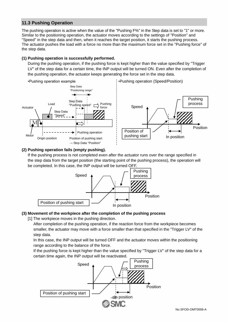
-48-
No.SFOD-OMT0006-A
11.3 Pushing Operation
The pushing operation is active when the value of the "Pushing F%" in the Step data is set to "1" or more. Similar to the positioning operation, the actuator moves according to the settings of "Position" and "Speed" in the step data and then, when it reaches the target position, it starts the pushing process. The actuator pushes the load with a force no more than the maximum force set in the "Pushing force" of the step data. (1) Pushing operation is successfully performed.
During the pushing operation, if the pushing force is kept higher than the value specified by "Trigger
LV" of the step data for a certain time, the INP output will be turned ON. Even after the completion of
the pushing operation, the actuator keeps generating the force set in the step data.
•Pushing operation example •Pushing operation (Speed/Position)
(2) Pushing operation fails (empty pushing).
If the pushing process is not completed even after the actuator runs over the range specified in
the step data from the target position (the starting point of the pushing process), the operation will
be completed. In this case, the INP output will be turned OFF.
(3) Movement of the workpiece after the completion of the pushing process
[1] The workpiece moves in the pushing direction.
After completion of the pushing operation, if the reaction force from the workpiece becomes
smaller, the actuator may move with a force smaller than that specified in the "Trigger LV" of the
step data.
In this case, the INP output will be turned OFF and the actuator moves within the positioning
range according to the balance of the force.
If the pushing force is kept higher than the value specified by "Trigger LV" of the step data for a
certain time again, the INP output will be reactivated.
Position of pushing start
Pushing process
In position
Position
Speed
Position of pushing start
Pushing process
In position
Position
Speed
Speed
Position of pushing start
Pushing process
In position
Position of pushing start
→ Step Data "Position"
Actuator
Origin position
Pushing operation Motor
Load
M
Pushing force
Position
Step Data
"Speed"
Step Data
"Positioning range"
Step Data
"Pushing speed"

-49-
No.SFOD-OMT0006-A
[2] Movement of the workpiece in the direction opposite to the pushing direction (The actuator is
pushed back since the reaction force from the workpiece is too large.)
After completion of the pushing operation, if the reaction force from the workpiece becomes
larger, the actuator may be pushed back. In this case, while the INP output is kept ON, the
actuator will be pushed back to the point where the reaction force and the actuator pushing
force are balanced (pushed back toward the target position).
If the actuator is pushed back over the target position, the alarm (ORIG ALM) will be activated.
11.4 Controller input signal response time
The controller input signal response delay include the following factors.
(1) Controller input signal scan delay
(2) Delay due to input signal analysis
(3) Delay of command analysis
Leave an interval of 15ms (30 ms if possible) or more between input signals and maintain the state of the signal for 30ms or more, as PLC processing delays and controller scanning delays can occur.
11.5 Methods of interrupting operation
There are 3 methods of interrupting operation and stopping the actuator during positioning operation and pushing operation, as shown below. The state after the interruption is different, therefore use the method appropriate to the application.
•Stopping by EMG signal
If the EMG signal is turned OFF during operation, after the actuator decelerates and stops, the servo will
turn OFF so the stopped position is not held.
(For an actuator with lock, it is held by the lock function.)
•Stopping by RESET signal
If the RESET signal is turned ON during operation, after the actuator decelerates and stops, the
stopped position is held.
(The servo does not turn OFF.)
•Stopped by HOLD signal
The actuator decelerates to stop when HOLD signal is ON during operation.
(The servo does not turn OFF.)
Caution If instructed to stop by EMG signal and RESET signal, all OUT signals will turn OFF.
In position
Speed
Position
Reaction force
Position of pushing start
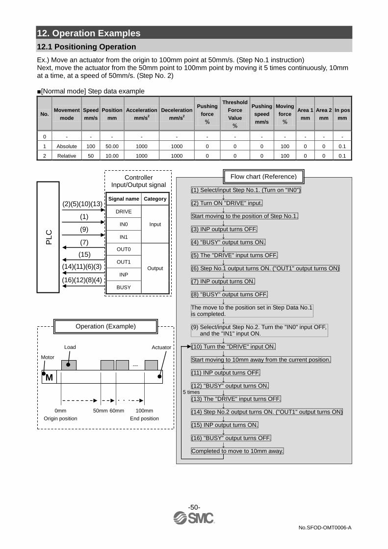
-50-
No.SFOD-OMT0006-A
12. Operation Examples
12.1 Positioning Operation
Ex.) Move an actuator from the origin to 100mm point at 50mm/s. (Step No.1 instruction) Next, move the actuator from the 50mm point to 100mm point by moving it 5 times continuously, 10mm at a time, at a speed of 50mm/s. (Step No. 2) ■[Normal mode] Step data example
No. Movement
mode
Speed
mm/s
Position
mm
Acceleration
mm/s2
Deceleration
mm/s2
Pushing
force
%
Threshold
Force
Value
%
Pushing
speed
mm/s
Moving
force
%
Area 1
mm
Area 2
mm
In pos
mm
0 - - - - - - - - - - - -
1 Absolute 100 50.00 1000 1000 0 0 0 100 0 0 0.1
2 Relative 50 10.00 1000 1000 0 0 0 100 0 0 0.1
(1) Select/input Step No.1. (Turn on "IN0") ↓
(2) Turn ON "DRIVE" input. ↓
Start moving to the position of Step No.1. ↓
(3) INP output turns OFF. ↓
(4) "BUSY" output turns ON. ↓
(5) The "DRIVE" input turns OFF. ↓
(6) Step No.1 output turns ON. ("OUT1" output turns ON) ↓
(7) INP output turns ON. ↓
(8) "BUSY" output turns OFF. ↓
The move to the position set in Step Data No.1 is completed.
↓ (9) Select/input Step No.2. Turn the "IN0" input OFF,
and the "IN1" input ON. ↓
(10) Turn the "DRIVE" input ON. ↓
Start moving to 10mm away from the current position. ↓
(11) INP output turns OFF. ↓
(12) "BUSY" output turns ON. ↓
(13) The "DRIVE" input turns OFF. ↓
(14) Step No.2 output turns ON. ("OUT1" output turns ON) ↓
(15) INP output turns ON. ↓
(16) "BUSY" output turns OFF. ↓
Completed to move to 10mm away.
Flow chart (Reference)
5 times
Actuator
0mm
Origin position
M
Motor
Load
---
100mm
End position
50mm 60mm
Operation (Example)
・・・
PL
C
(2)(5)(10)(13)
(14)(11)(6)(3)
(16)(12)(8)(4)
(15)
(7)
(9)
(1)
Controller Input/Output signal
Signal name Category
DRIVE
Input IN0
IN1
OUT0
Output
OUT1
INP
BUSY

-51-
No.SFOD-OMT0006-A
12.2 Pushing Operation
Ex.) Move an actuator from the origin to 100mm point at 100mm/s. (Step Data No.1 is used for this operation.) From the 100mm point, the actuator starts the pushing operation of 10mm/s speed and 50% or less force. (the pushing distance is up to 5mm). Then, the actuator moves from the position where the pushing operation was completed (where INP was turned ON) to the 50mm point with 50mm/s. (Step Data No.2 is used for this operation.)
■[Normal mode] Step data example
No. Movement
mode
Speed
mm/s
Position
mm
Acceleration
mm/s2
Deceleration
mm/s2
Pushing
force
%
Threshold
Force
Value
%
Pushing
speed
mm/s
Moving
force
%
Area 1
mm
Area 2
mm
In pos
mm
0 - - - - - - - - - - - -
1 Absolute 100 100.00 1000 1000 50 40 10 100 0 0 5
2 Absolute 50 50.00 1000 1000 0 0 0 100 0 0 0.1
(1) Select/input Step No.1. (Turn on "IN0")
↓ (2) Turn ON "DRIVE" input.
↓ Start moving to the position of Step No.1.
↓ (3) INP output turns OFF.
↓ (4) "BUSY" output turns ON.
↓ (5) The "DRIVE" input turns OFF.
↓ Move at low speed after passing the "Position" of the Step No.1.
↓ Push the workpiece with the specified pushing force.
↓ (6) Step No.1 output turns ON. ("OUT1" output turns ON)
↓ (7) INP output turns ON.
↓ (8) "BUSY" output turns OFF.
↓ The move to the position set in Step No.1 is completed.
↓ (9) Select/input Step No.2. (Turn the "IN0" input OFF,
and the "IN1" input ON.) ↓
(10) Turn ON "DRIVE" input. ↓
Start moving to the position of Step No.2. ↓
(11) INP output turns OFF. ↓
(12) "BUSY" output turns ON. ↓
(13) The "DRIVE" input turns OFF. ↓
(14) Step No.1 output turns ON. ("OUT1" output turns ON) ↓
(15) INP output turns ON. ↓
(16) "BUSY" output turns OFF. ↓
The move to the position set in Step No. 2 is completed.
Flow chart (Reference)
Actuator
100mm
Actuator
0mm
Origin position
Pushing operation
with pushing force
Motor
Load
M
Step No.1 Pushing operation (Example)
PL
C
(2)(5)(10)(13)
(14)(11)(6)(3)
(16)(12)(8)(4)
(15)
(7)
(9)
(1)
Controller Input/Output signal
Signal name Category
DRIVE
Input IN0
IN1
OUT0
Output
OUT1
INP
BUSY
Step No. 2 positioning operation (Example)
50mm
End position
Motor
M
Load
Pushing completed
position

-52-
No.SFOD-OMT0006-A
13. Operation Instructions
13.1 Overview of the Operation Instructions
Shows operation instruction method of each function shown in 8. Operation methods (P.31).
13.2 Operation procedure for Operation by Step No.
Refer to the following "Procedures" and "Timing charts" for details of the Return to Origin, operation mode procedures and the signal timing. Refer to 9.1 Memory allocation (P.32) for the memory allocation of signals. [1] Power on and Return to Origin position - Procedure - - Timing chart - (1) Turn the power supply ON. (2) Turn the "SVON" input ON. (3) SVRE is turned ON.
The time [SVRE] output turns ON is dependent on the type of actuator and the customer usage.
The actuator with lock is unlocked.
(4) Turn "SETUP" input ON. (5) BUSY output turns ON.
(The actuator starts the operation.) After BUSY output is turned ON, SETUP input is turned OFF.
(6) SETON, INP output is turned ON.
Return to origin is completed when BUSY output is turned OFF.
Timing chart/Return to origin
SVON
SETUP
BUSY
SVRE
SETON
INP
External lock
Output
signal
Input
signal
Power supply
Speed
24V
0V
INP s ignal is O N when the current
pos ition is within the s tep data pos ition
range. O therwis e, the s ignal is O F F
Unlock
Held
Return to origin
ONOFF
ONOFF
0mm/s
.
.
.
.
.
.
.
.

-53-
No.SFOD-OMT0006-A
[2] Positioning operation - Procedure - - Timing chart - (1) Input step data No. (IN0 to IN5) (2) Turn the "DRIVE" input ON.
(INP signals being output are turned OFF.) Scan the specified step data number (from IN0 to IN5).
(3) BUSY output turns ON.
(and the positioning movement starts.) After BUSY output is ON, if
DRIVE is turned OFF, the step data number will be output (from the outputs OUT0 to OUT5).
(4) When INP turns ON and BUSY
turns OFF, the positioning operation will be completed.
Power supply
IN0 to 5
SVON
DRIVE
OUT0 to 5
BUSY
SVRE
SETON
INP
External lock
Output signal
Input signal
Positioning operation
Speed
24V
0V
Unlock Held
ON OFF
ON OFF
0mm/s
- -
-
-
-
-
-
-
-
-
-
-
Min15ms
Input Step Data No. Read Step data No.
Output Step Data No.
If the current position is inside of step data positioning, the INP signal is ON. Otherwise, the signal is OFF
Don’t care

-54-
No.SFOD-OMT0006-A
[3] Pushing Operation - Procedure - - Timing chart - (1) Input of step data No. (IN0 to IN5)
(2) Turn the "DRIVE" input ON.
(INP signals being output are turned OFF.) →Scan the step data number
(from IN0 to IN5).
(3) BUSY is ON when pushing starts
After BUSY output is ON, if DRIVE is turned OFF, the stepdata number will be output (from the outputs
OUT0 to OUT5).
4) When INP output is turned ON and BUSY is turned OFF, the pushing operation will be completed (the actuator generates the force larger than that specified in "TriggerLV" of the step data).
[4] HOLD - Procedure - - Timing chart - (1) During operation (BUSY output is ON)
Turn on HOLD input
(2) BUSY output turns OFF. (The actuator stops.)
(3) HOLD output is turned OFF.
(4) BUSY output turns ON.
(The actuator restarts.)
Power supply
IN0 to 5
SVON
DRIVE
OUT0 to 5
BUSY
SVRE
SETON
INP
External lock
Pushing operation
Input signal
Output signal
Speed 0mm/s
24V 0V
Unlock Held
ON OFF
ON OFF
- - - -
-
-
Input Step Data No.
Min15ms
Read Step data No.
Output Step Data No.
- - - - - - - - -
-
INP signal turns ON when pushing force exceeds the "Trigger LV" value of step data.
Don’t care
HOLD
BUSY
HOLD during operation
Input signal Output signal Deceleration
Start point
Speed 0mm/s
ON OFF
ON OFF

-55-
No.SFOD-OMT0006-A
[5] Reset -Procedure- [Driving reset] - Timing chart - Reset (1) During operation (BUSY output is ON)
RESET is turned ON.
(2) BUSY output, OUT0 to OUT3 output is OFF.
-Procedure- [Alarm Reset] (1) Alarm generated
(ALARM is turned OFF and the output OUT0 to OUT3 is turned ON.)
(2) RESET is turned ON.
(3) ALARM output turns OFF, OUT0
to OUT3 turns OFF. (The alarm is deactivated.)
[6] Stop - Procedure - - Timing chart - (1) During operation (BUSY output is ON)
Turn OFF EMG input. (Stop command)
(2) ESTOP output turns ON.
(3) BUSY output turns OFF. (The actuator stops.) SVRE output turns OFF. The actuator with lock is locked.
(4) EMG input turns ON. [The stop release
command]
(5) ESTOP output turns OFF. SVRE output turns ON. The actuator with lock is unlocked.
- Timing chart - Alarm Reset
When "Stop" is OFF, the stop is activated.
RESET
OUT0 to 5
BUSY
INP
Output signal
Input signal
ON OFF
ON OFF ON
OFF
OFF ON
Speed 0mm/s Deceleration Start point
INP is ON when stop position is within the positioning range.
RESET
OUT0 to 5
ALARM
Output signal
Input signal
Alarm generated
ON OFF
ON OFF
ON OFF
Power supply
Emergency stop
SVON
BUSY
SVRE
SETON
INP
ALARM
ESTOP
Condition of external brake
Emergency stop during operation
Output signal
Input signal
Deceleration Start point
Speed
0mm/s
24V 0V
Held
ON OFF
ON OFF
ON OFF
If the now position is inside of step data positioning, the INP signal is ON. Otherwise OFF.
- - - - - - - - - -

-56-
No.SFOD-OMT0006-A
[7] Area output - Procedure - Timing chart ●Step data No.1 operation (1) Input step data No. (IN0 to IN5) (2) Turn the "DRIVE" input ON.
→ Receive the step data no.1 (from the input IN0 to IN5).
(3) BUSY output turns ON.
(The actuator starts the operation.) INP is turned OFF. After BUSY output turns
OFF, if the DRIVE input turns OFF, the step data No.1 (OUT0 to OUT5) will be output.
(4) AREA output of step data No.1
turns ON. (at 150mm from the origin point)
(5) BUSY output turns OFF.
(The actuator stops.) INP is turned ON.
●Step data No.2 operation (6) Input of step data No. (IN0 to IN5)
(7) Turn the "DRIVE" input ON.
Read step data No. 2 (IN0 to IN5 input)
(8) AREA output turns OFF. The BUSY output turns ON. (The actuator starts the operation.) INP is turned OFF. After BUSY output turns OFF, if the DRIVE input turns OFF, the step data No.2 (OUT0 to OUT5) will
be output.
(9) AREA output of step data No.2 turns ON. (at 170mm from the origin point)
(10) AREA output of step data No.2 turns OFF. (at 130mm from the origin point)
(11) BUSY output turns OFF. (The actuator stops.) INP is turned ON.
The initial position: 50mm
Operation of Step Data No.1: Position: 200mm AREA1 to AREA 2: 150 to 250mm
Operation of Step Data No.2: Position: 100mm AREA 1 to AREA 2: 130 to 170mm IN0 to 5
DRIVE
OUT0 to 5
BUSY
INP
AREA
50mm 200mm 100mm 170mm 130mm
Operation of Step Data No.1
Operation of Step Data No.2
Input signal
Output signal
If the current position is within the In position range, the INP signal is ON. Otherwise, the signal is OFF
150mm Speed 0mm/s
ON OFF
ON OFF
Min15ms Min15ms
If the current position is inside of 1, and 2 area scope for step data., the AREA signal is ON. Otherwise, the signal is OFF
- -
- - - - - - -
Don’t care
Don’t care

-57-
No.SFOD-OMT0006-A
13.3 Operation procedure for Operation by numerical instruction
Ex.) Input 50.00 [mm] to the position parameter of the specified step data and start the actuator.For parameters other than
position which are numerically specified (speed, acceleration/deceleration), values set to the specified step data are
used.
Before starting the operation by numerical instruction, make sure that the servo is on and returning to origin has
completed.
(1) Confirm that Word2, bit0:
Start flag = OFF
Input OFF when Word2, bit0:
Start flag = ON.
(2) Input the step data No. to be
specified by Word0: IN0 to 5
(bit0 to 5)
1 to 5: IN1 to 5 = OFF
(3) Word1, bit4 to 15: With a numerical
input flag, input ON to the
parameter bit which is numerically
instructed by specified step data.
Input OFF to the parameter bit which
is not numerically instructed.
Ex.) Only [position] of the numerical
data input flag is specified by
number.
→ Word1, bit6=ON,
Word1, bit4 to 5, 7 to 15=OFF.
(4) Word2, bit8 to 9: Input operation
method and numerical parameter
data for Word3 to 17.
Ex.) Input [Position] 50.00 [mm].
5000[0.01mm]=(00001388)h
→Word4: Target position (L)
= (1388)h
Word5: Target position
(H) = (0000)h
(5) Input the numerical data input flag
bit and numerically specified
parameter data, and then, input
Word2, bit0: Start flag=ON.
Operation instruction data will be transmitted with the start flag ON.
(6) During the actuator operation, Word0: BUSY=ON is output.
(7) When the actuator reached the target position, Word0: INP=ON is output.
(Refer to "INP" section (P.34) for signal ON conditions)
When the actuator operation completes, Word0: BUSY=OFF is output.
The completion of the specified operation is validated when both Word0: INP=ON and
Word0: BUSY=OFF are established at the same time.
Timing chart/numerically instructed operation
(DRIVE signal is not used) OFF
Power supply
INP
SETON
Numerical data input flag
DRIVE
External lock
Output signal
Input signal
IN0 to 5
SVON
Start flag
Data (position)
BUSY
SVRE
Speed
24V
0V
Unlock
Held
ON OFF
ON OFF
0mm/s
(1)
(2)
(3)
(5)
(7)
(4)
ON
Min 15ms
- - - -
- - - -
- - -
- - - -

-58-
No.SFOD-OMT0006-A
14. Options
14.1 Actuator cable [5m or shorter]
14.2 Actuator cable [8 to 20m]
Produced upon receipt of order
Only "Robotic type cable" can
be selected.
(2)
LE-CP- □ - □ Signal name Terminal number
A B-1
A A-1
B B-2
B A-2
COM-A/COM B-3
COM-B/ - A-3
Vcc B-4
GND A-4
A B-5
A A-5
B B-6
B A-6
Cable color Terminal number
Brown 2
Red 1
Orange 6
Yellow 5
Green 3
Blue 4
Cable color Terminal number
Brown 12
Black 13
Red 7
Black 6
Orange 9
Black 8
- 3
Shield
(1) (2)
(3)
L
(14.2)
(17
.7)
(11) (30.7)
(14
) (1
8)
B1 A1
A6 B6
5
6
2 1
15
16
2 1
Actuator side Controller side
(1) (2)
(3)
Cable length (L)
1 1.5m
3 3m
5 5m
Cable length (L)
8 8m *
A 10m *
B 15m *
C 20m *
Signal name Terminal number
A B-1
A A-1
B B-2
B A-2
COM-A/COM B-3
COM-B/ - A-3
Vcc B-4
GND A-4
A B-5
A A-5
B B-6
B A-6
Cable color Terminal number
Brown 2
Red 1
Orange 6
Yellow 5
Green 3
Blue 4
Cable color Terminal number
Brown 12
Black 13
Red 7
Black 6
Orange 9
Black 8
- 3
Shield
(1) (2)
(3)
L
(14.2)
(17
.7)
(11) (30.7)
(18
)
B1 A1
A6
B6
5
6
2 1
15
16
2 1
Actuator side Controller side
(1)
(3)
(14
)
(ø8)
(ø5.5)
(ø6.3)
Nil Robotic type cable
S Standard cable
Actuator cable type
LE-CP- □

-59-
No.SFOD-OMT0006-A
14.3 Actuator cable for with lock [5m or less]
Actuator cable type
14.4 Actuator cable for with lock [8 to 20m]
Produced upon receipt of order
Only "Robotic type cable" can be selected.
L
(14.2)
(17
.7)
(11) (30.7)
(14
) (1
8)
B1 A1
A6
B6 5
6
2 1
15
16
2 1
Actuator side Controller side
(1) (2)
(3) B1 A1
B3 A3
(4)
(10
.2)
Cable length (L)
1 1.5m
3 3m
5 5m
Signal name Terminal number
A B-1
A A-1
B B-2
B A-2
COM-A/COM B-3
COM-B/ - A-3
Vcc B-4
GND A-4
A B-5
A A-5
B B-6
B A-6
Cable color Terminal number
Brown 2
Red 1
Orange 6
Yellow 5
Green 3
Blue 4
Cable color Terminal number
Brown 12
Black 13
Red 7
Black 6
Orange 9
Black 8
- 3
Red 4
Black 5
Brown 1
Blue 2
Shield
(1) (2)
Signal name Terminal number
Lock (+) B-1
Lock (-) A-1
Sensor (+) B-3
Sensor (-) A-3
(4)
(3)
Cable length (L)
8 8m
A 10m
B 15m
C 20m
L
(14.2)
(17
.7)
(11) (30.7)
(14
) (1
8)
B1 A1
A6
B6
5
2
2 1
15
16
6
1
Actuator side Controller side
(1)
(2)
(3) B1 A1
B3 A3
(4) (1
0.2
)
(ø5.5)
(ø5.7)
(ø6.3)
(ø8)
(ø5.7)
Nil Robotic type cable
S Standard cable
Signal name Terminal number
A B-1
A A-1
B B-2
B A-2
COM-A/COM B-3
COM-B/ - A-3
Vcc B-4
GND A-4
A B-5
A A-5
B B-6
B A-6
Cable color Terminal number
Brown 2
Red 1
Orange 6
Yellow 5
Green 3
Blue 4
Cable color Terminal number
Brown 12
Black 13
Red 7
Black 6
Orange 9
Black 8
- 3
Red 4
Black 5
Brown 1
Blue 2
Shield
(1) (2)
Signal name Terminal number
Lock (+) B-1
Lock (-) A-1
Sensor (+) B-3
Sensor (-) A-3
(4)
(3)
LE-CP- □ - B- □
LE-CP- □ - B
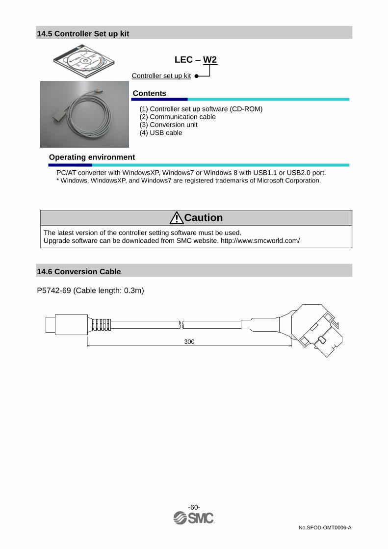
-60-
No.SFOD-OMT0006-A
14.5 Controller Set up kit
Caution The latest version of the controller setting software must be used. Upgrade software can be downloaded from SMC website. http://www.smcworld.com/
14.6 Conversion Cable
P5742-69 (Cable length: 0.3m)
LEC – W2
Controller set up kit
Contents
(1) Controller set up software (CD-ROM) (2) Communication cable (3) Conversion unit (4) USB cable
Operating environment
PC/AT converter with WindowsXP, Windows7 or Windows 8 with USB1.1 or USB2.0 port. * Windows, WindowsXP, and Windows7 are registered trademarks of Microsoft Corporation.

-61-
No.SFOD-OMT0006-A
14.7 Teaching box
No Indication Function
(1) LCD Liquid crystal display (with backlight)
(2) Ring The ring to hang the teaching box.
(3) Stop switch
When the switch is pressed, the switch
locks and it stops.
Turn clockwise to release the lock.
(4) Stop guard Protector for the stop switch
(5) Enable
switch
(Option)
Switch to prevent unintentional
operation of Jog test function.
Does not apply to other functions e.g.
data change
(6) Key switch Entry switches
(7) Cable 3m length
(8) Connector The connector to be connected to the
CN4 of the controller
Teaching box
Cable length
3m 3
Enable switch
Equipped with enable switch
S
No enable switch
Nil
Original language
Stop switch
With Stop switch G English E
Japanese J
Dimensions
(8)
(3)
(7)
(6)
(5)
(1)
(2)
(4)
LEC- T1 - 3 □ G □

-62-
No.SFOD-OMT0006-A
15. Alarm for Motor Control
The details of the alarm for motor control can be checked using a PC (the controller setting software) or the teaching box.
Please refer to the manuals of the controller setting software or the teaching box for details of the alarms.
When an alarm is generated, deactivate the alarm after troubleshooting and correcting the error with reference to chapter "15.2 Alarms and countermeasures" (P.63). Alarms are divided into two types. One is an alarm group B to D which can be cleared by inputting the signal RESET. The other is group E which cannot be cleared unless the power supply control (24 VC) is turned oFF once.
15.1 Remote IO signal output for alarm group
This product outputs a signal to distinguish the type of the alarm when an alarm is generated. Alarms are classified into 5 groups. When an alarm is generated, it is output in OUT0 to 3. Table below shows the combination of the alarm group and remote IO signal output (OUT0 to OUT3).
Alarm group Remote IO signal output
ALARM OUT0 OUT1 OUT2 OUT3
Alarm group B ON OFF ON OFF OFF
Alarm group C ON OFF OFF ON OFF
Alarm group D ON OFF OFF OFF ON
Alarm group E ON OFF OFF OFF OFF
After generation of the alarm, SVRE or SETON are output according to the contents of the alarm as shown below.
Alarm group Remote IO signal output
How to start test run. SVRE SETON
Alarm group B No change No change Input RESET
Alarm group C No change No change Input RESET
Alarm group D OFF No change Input RESET, then SVON.
Alarm group E OFF OFF Power supply for control is turned OFF
→ Supply again
- Procedure to restart operation when alarm group D is generated -
Procedure 1 Alarm group D is generated → "SVRE" changes to OFF (Servo is OFF)
Procedure 2 Input RESET → (Alarm is canceled) → After inputting SVON, SVRE is turned ON
(Servo is on)

-63-
No.SFOD-OMT0006-A
15.2 Alarms and countermeasures
Name of the
controller
setting
software
(code) 1
Teaching
box
description
Group How to
deactivate Alarm contents/Countermeasure
Drive data
value is
wrong
(01-048)
Step
dataALM1 B RESET
<Condition>The step data is incorrect for the following conditions
(Settable range)
(1) Area1 <Area2
(If both Area1 and Area2 is 0, the alarm will not be activated.)
(2) Trigger LV ≤ Pushing force
(3) Minimum speed of actuator ≤ Pushing speed ≤ Speed
(4) Pushing speed ≤ Maximum pushing speed of actuator
(5) Pushing force ≤ Minimum pushing force of actuator
(6) Basic parameter "Maximum pushing force" ≥Minimum pushing force
of the actuator
(7) Basic parameters "Max pushing force" ≥ Threshold
<Countermeasure> Modify the step data and basic parameters setting
Caution
Please refer to the manual or the catalogue of the actuator for the
max/min pushing force/speed for the actuator.
Parameter
value is
wrong
(01-049)
Parameter
ALM B RESET
<Contents> The basic parameter is not correct for the following condition:
(Settable range)
(1) Stroke(-) < Stroke (+)
(2) W-Area 1 < W-Area 2
( If both W-Area1 and W-Area2 is 0, the alarm will not be activated.)
(3) Maximum pushing force < Maximum pushing force of actuator
<Countermeasure> Modify the basic parameter setting.
Caution
Please refer to the manual or the catalogue of the actuator for the
maximum pushing force for the actuator.
Set step
data is not
registered
on list.
(01-051)
Step data
ALM2 B RESET
<Contents> For an operation for a specific step data no., the requested
number of the step data is not registered. (When operation is
commanded through PLC, this alarm will be generated depending on the
input signal interval and the holding time of signals)
< Countermeasure >
(1) Check if "Operation" of the step data which is commanded to start is
"Blank (Invalid data)".
(2) Leave an interval of 15ms or more (recommendation is 30 ms)
between input signals and maintain the state of the signal for 15ms or
more (recommendation is 30 ms), because PLC processing delays
and controller scanning delays can occur.
Refer to 13.2[2] Positioning operation (P.53)
Set stroke
is outside
the stroke
Stroke
limit B RESET
<Contents> The actuator goes outside the stroke limit specified by the
basic parameters, "Stroke (+)" and "Stroke (-)" if it performs the requested
operation. (Including JOG operation after return to origin)

-64-
No.SFOD-OMT0006-A
limit.
(01-052)
<Countermeasure> Make sure that the basic parameters, "Stroke (+)"
and "Stroke (-)" are consistent with the distance of actuator movement
specified in the step data.
Caution
If the operation method of step data is "relative coordinated
movement", note the location where the operation starts and the
distance traveled. If the location is out of the stroke range when the
power is supplied, this alarm is generated. Move the table within
stroke range, and supply power.
Reacting
force is
outside limit
when
pushing.
Position is
unstable.
(01-096)
Pushing
ALM C RESET
<Contents> In the pushing operation, the actuator is pushed back from
the pushing operation origin position.
<Countermeasure> Increase the distance from the pushing operation
origin position to the object being pushed. Or, increase the pushing force.
Return to
ORIG did
not
complete in
the set time.
(01-097)
ORIG ALM C RESET
<Contents> Return to origin is not completed within the set time.
<Countermeasure> Make sure there are no obstructions that interfere with
the actuator movement.
Drive is ON
when SVRE
is OFF
(01-098)
Servo OFF
ALM C RESET
<Contents> While the servo motor is oFF, the return to origin operation,
positioning operation, pushing operation or JOG operation is requested.
<Countermeasure> Modify the setting so that those operations will be
requested while the servo motor is ON (the SVON input is ON).
Drive is ON
when
SETON is
OFF
(01-099)
Drive ALM C RESET
<Contents> A positioning operation or pushing operation is requested
before the return to origin position is completed.
<Countermeasure> Modify the setting so that these operations will be
requested after the return to origin position is completed.
Did not
detect
sensor
when
returning to
ORIG.
(01-103)
ORIG
Sens ALM C RESET
<Contents> Alarm is generated when return parameter has the conditions
1, 2 shown below.
Return to origin parameter setting
Return to origin mode ORIG sensor
1 Pushing origin operation [Stop] •Sensor N.O type [N.O]
2 Limit switch origin [Sensor]
•The origin sensor is not
effective. [Disabled]
or
•Sensor N.O type [N.O]
Alarm is generated with the conditions above when the sensor is not
mounted to the actuator.
<Countermeasure> Check the sensor installation and settings of the return
to origin parameter.
Speed
exceeded
set value
(01-144)
Over
speed D
RESET
Input
SVON
<Contents> The motor speed exceeds a specific level due to an external
force, etc.
<Countermeasure> Make improvements so that the motor speed will not
exceed the maximum speed of the actuator.
Caution
Please refer to the manual or the catalogue of the actuator for the
maximum speed of the actuator.
Motor Over D RESET <Contents> The motor power supply voltage is out of range during [SVON].

-65-
No.SFOD-OMT0006-A
power
supply
voltage is
outside set
range.
(01-145)
motorVol Input
SVON
<Countermeasure> Make sure that the voltage supplied to the motor
power (M24V) of the controller is within specification.
Caution
If the power supply is "inrush-current control type", a voltage drop may
cause an alarm during acceleration/deceleration.
<Contents> The alarm may be caused by regenerative power depending
on the method of operation of the actuator.
<Countermeasure> Make sure that the operating conditions are within
the specifications.
Caution
Please refer to the manual or the catalogue of the actuator for the
method of operation of the actuator.
Controller
temperature
exceeded
set range.
(01-146)
Over
Temp D
RESET
Input
SVON
<Details> The temperature around the power element of the controller is
too high.
<Countermeasures> Make improvements so that the temperature around
the controller is kept appropriate.
Controller
supply
voltage is
outside set
range.
(01-147)
Over
CrtlVol D
RESET
Input
SVON
<Contents> The control power supply voltage within the controller is
outside the set range.
<Countermeasure> Make sure that the voltage supplied to the control
power (C24V) of the controller is appropriate.
Caution
If a single power supply is used for both the control power and the
motor power, or the power supply is "inrush-current control type", a
power voltage drop may be caused due to a voltage drop during
acceleration/deceleration.
<Contents> The alarm may be caused by regenerative power depending
on the method of operation of the actuator.
<Countermeasure> Make sure that the operating conditions are within the
specifications.
Caution
Please refer to the manual or the catalogue of the actuator for the
method of operation of the actuator.
Current
limit is
exceeded
(01-148)
Over load D
RESET
Input
SVON
<Contents> The output current accumulated value exceeds the specified
value.
<Countermeasure> Make sure there are no obstructions that interfere
with the actuator movement. Also, make sure that the load, speed,
acceleration and deceleration are within the range of the actuator.
Communic
ation error.
(01-150)
Ctrl Comm
ALM D
RESET
Input
SVON
<Contents> The connection with the higher-level devices (such as the PC
and teaching box) is disconnected.
<Contents> The connection with the higher-level devices (such as the PC
and teaching box) is disconnected.
In case of the communication failure of PC or teaching box, resetting of
alarm by PC or teaching box is possible after connecting again.
Encoder
error
(01-192)
Encoder
ALM E
Cycle
the
power
supply
for the
controller
<Contents> Abnormality in communication with the encoder.
<Countermeasure> Check the connection of the actuator cable.
Unable to
find motor
phase in
set time.
(01-193)
Polarity
not found E
Cycle
the
power
supply
for the
<Contents> Unable to find the motor phase within the set time.
(When the servo motor is turned ON (SVON is turned ON) for the first time
after the power is applied, the actuator needs to move a little to find the
motor phase. However, if this actuator movement is prevented, this alarm
will be activated.)

-66-
No.SFOD-OMT0006-A
controller <Countermeasure> Make sure there are no obstructions that interfere with the
actuator movement and then turn ON the servo motor (SVON is turned ON).
Output
current limit
is
exceeded
set value
(01-194)
Over
current E
Cycle
the
power
supply
for the
controller
<Contents> The output current of the power circuit is abnormally high.
<Countermeasure> Make sure that there are no short circuits of actuator
cables, connectors, etc.
In addition, make sure that the actuator is compatible with the controller.
Error
counter
overflowed
(01-196)
Err
overflow E
Cycle
the
power
supply
for the
controller
<Contents> An overflow of the position error counter inside of the
controller has occurred.
<Countermeasure> Make sure there are no obstructions that interfere
with the actuator movement. Also, make sure that the load, speed,
acceleration and deceleration are within the range of the actuator.
Memory
Abnormalit
y has
occurred
(01-197)
Memory
ALM E
Cycle
the
power
supply
for the
controller
<Contents> An error of the EEPROM has occurred.
<Countermeasure> Please contact SMC. (The write limit of the EEPROM
is roughly 100,000 times)
CPU error
(01-198)
CPU
failure E
Cycle
the
power
supply
for the
controller
<Contents> The CPU is not operating normally.
(It is possible that the CPU or surrounding circuits has failed, or the CPU
is malfunctioning due to electrical noise).
<Countermeasure> If the alarm cannot be deactivated even after the
power is reapplied, please contact SMC.

-67-
No.SFOD-OMT0006-A
16. Precautions for wiring and cable
Warning
(1) Adjusting, mounting or wiring change should never be done before shutting OFF the power supply to the product. Electric shock, malfunction and damage can result.
(2) Do not disassemble the cable. Use only specified cables.
(3) Do not connect or disconnect the cable or connector with the power on.
Caution
(1) Wire the connector securely. Do not apply any voltage to the terminals other than those specified in the Operation Manual.
(2) Wire the connector securely. Check for correct connector wiring and polarity.
(3) Take appropriate measures against noise. Noise in a signal line may cause malfunction. As a countermeasure, high voltage and low voltage cables should be separated, and keep wiring lengths short, etc.
(4) Do not route wires or cables together with power or high voltage cables. The product may malfunction due to interference and surge voltages. Route the wires of the product separately from power or high voltage cables.
(5) Take care that actuator movement does not damage cables.
(6) Operate with cables secured. Avoid bending cables at sharp angles where they enter the product.
(7) Avoid twisting, folding, rotating or applying an external force to the cable. Also avoid operating at sharp angles. Risk of electric shock, broken wires, contact failure and loss of control of the product can occur.
(8) Fix the motor cable protruding from the product in place before using. The motor cable is not robotic type cable and can be damaged when moved. Do not place Part A in the diagram below in a flexible cable duct.
(9) Select "Robotic type cables" when deflecting actuator-cables repeatedly. Do not put cables into a flexible moving tube with a radius smaller than the specified value (minimum 50mm). Risk of electric shock, wire damage, contact failure and loss of control of the product can occur if "Standard cables" are used in case of inflecting the cables repeatedly.
(10) Confirm proper wiring of the product. Insulation failure (interference with another circuit, poor insulation between terminals etc.) could introduce excessive voltage or current to the controller or its peripheral devices and damage them.
(11) The Speed/pushing force may vary, depending on the cable length, load and mounting conditions etc. If the cable length exceeds 5m, the speed/pushing force will be reduced 10% per 5 m maximum. (If cable length is 15m, 20% reduction maximum.)
Transport Caution
(1) Do not carry or swing the product by the motor or the cable.
Connector
Motor cable
Actuator cable Robotic type cable (High flexibility cable)

-68-
No.SFOD-OMT0006-A
17. Electric Actuators/Common Precautions
17.1 Design and selection
Warning
(1) Read the Operation Manual before using the product. Handling or usage/operation other than that specified in the Operation Manual may lead to breakage and product failure. Any damage attributed to use beyond the specifications is not guaranteed.
(2) There is a possibility of dangerous sudden action by the product if sliding parts of machinery are twisted due to external forces etc. In such cases, human injury may occur, such as catching hands or feet in the machinery, or damage to the machinery itself may occur. The machinery should be designed to avoid such dangers.
(3) A protective cover is recommended to minimize the risk of personal injury. If a driven object and moving parts of the product are in close proximity, personal injury may occur. Design the system to avoid contact with the human body.
(4) Securely tighten all stationary parts and connected parts so that they will not become loose. When the product operates with high frequency or is installed where there is a lot of vibration, ensure that all parts remain secure.
(5) Consider a possible loss of power source. Take measures to prevent injury and equipment damage in the case of a power supply failure.
(6) Consider the behavior of an emergency stop of the whole system. Design the system so that human injury and/or damage to machinery and equipment will not be caused, when it is stopped by a safety device for abnormal conditions such as a power outage or a manual emergency stop of the whole system.
(7) Consider the action when operation is restarted after an emergency stop or abnormal stop of the whole system. Design the system so that human injury or equipment damage will not occur upon restart of operation of the whole system.
(8) Disassembly and modification is prohibited. Do not disassemble the product or make any modifications, including additional machining. This may cause human injury and/or an accident.
(9) Do not use the stop signal, "EMG" of the controller and stop switch on the teaching box as the emergency stop for the system. The stop signal, "EMG" of the controller and the stop switch on the teaching box are for decelerating and stopping the actuator. Design the system with an emergency stop circuit which is applied to the relevant safety standard separately.
(10) When using for vertical applications, it is necessary to build in a safety device. The rod may fall due to the weight of the work. The safety device should not interfere with normal operation of the machine.
Caution
(1) Use the product for the maximum usable stroke. The product will be damaged if it is used with a stroke exceeding the maximum stroke. Refer to the specifications of the product.
(2) When the product repeatedly cycles with partial strokes, operate it at a full stroke at least once a day or every 1,000 strokes. Otherwise, lubrication can be lost.
(3) Do not use the product in applications where excessive external force or impact force is applied to it. The product can be damaged. Components, including the motor, are manufactured to precise tolerances, so the sligh test deformation may cause faulty operation or seizure.
(4) Return to origin cannot be carried out during operating. This function cannot be carried out during positioning operation or pushing operation.

-69-
No.SFOD-OMT0006-A
(5) Refer to a common auto switch (Best Pneumatics No 2), when an auto switch is built and used within the system.
s
17.2 Mounting
Warning
(1) Install and operate the product only after reading the Operation Manual carefully and understanding its contents. Keep the manual in a safe place for future reference.
(2) Tighten threads with the proper tightening torque. Tighten the screws to the recommended torque for mounting the product.
(3) Do not make any alterations to this product. Alterations made to this product may lead to a loss of durability and damage to the product, which can lead to human injury and damage to other equipment and machinery.
(4) When using an external guide, the guide axis should be parallel to the actuator axis. There will be damage/excessive wear on the lead screw if the external guide is not parallel.
(5) When an external guide is used, connect the moving parts of the actuator and the load in such a way that there is no interference at any point within the stroke. Do not scratch or dent the sliding parts of the actuator tube or piston rod etc., by striking them with other objects. Components are manufactured to precise tolerances, so the slightest deformation may cause faulty operation.
(6) Prevent the seizure of rotating parts (pins, etc.) by applying lubricating grease.
(7) Do not use the product before verifying that the equipment can operate properly. After mounting or repair, connect the power supply to the product and perform appropriate functional inspections to check it is mounted properly.
(8) Cantilever When the actuator is operated at high speeds while it is fixed at one end and free at the other end (flange type, foot type, double clevis type, direct mount type), a bending moment may act on the actuator due to vibration generated at the stroke end, which can damage the actuator. In such a case, install a support bracket to suppress the vibration of the actuator body or reduce the speed so that the actuator does not vibrate. Use a support bracket also when moving the actuator body or when a long stroke actuator is mounted horizontally and fixed at one end.
(9) When mounting the actuator or attaching to the work piece, do not apply strong impact or large moment. If an external force over the allowable moment is applied, it may cause looseness in the guide unit, an increase in sliding resistance or other problems.
(10) Ensure sufficient space for maintenance activities. Allow sufficient space for maintenance and inspection.

-70-
No.SFOD-OMT0006-A
17.3. Handling Precautions
Warning
(1) Do not touch the motor while in operation. The surface temperature of the motor can increase to approx. 90
oC to 100
oC due to operating
conditions. Energizing alone may also cause this temperature increase. Do not touch the motor when in operation as it may cause burns.
(2) If abnormal heating, smoking or fire, etc., occurs in the product, immediately shut OFF the power supply.
(3) Immediately stop operation if abnormal operation noise or vibration occurs. If abnormal operation noise or vibration occurs, the product may have been mounted incorrectly. Unless operation of the product is stopped for inspection, the product can be seriously damaged.
(4) Never touch the rotating part of the motor or moving part of the actuator while in operation.
(5) When installing, adjusting, inspecting or performing maintenance on the product, controller and related equipment, shut OFF the power supply to each of them. Then, lock it so that no one other than the person can turn the power on, or implement measures such as a safety plug.
(6) In the case of the actuator that has a servo motor (24VDC), the "motor phase detection step" is done by inputting the servo on signal just after the controller power is turned ON. The "motor phase detection step" moves the table/rod for the distance of one screw-lead maximum. (The motor rotates in the reverse direction if the table hits an obstacle such as the end stop damper.) Take the "motor phase detection step" into consideration for the installation and operation of this actuator.
Caution
(1) Keep the controller and actuator combination as delivered for use. The product parameters are set before shipment. If the controller is combined with a different actuator, failure can result.
(2) Check the product for the following points before operation. a) Damage to power supply line and signal line b) Looseness of the connector to the power and signal lines c) Looseness of the actuator/cylinder and controller/driver mounting d) Abnormal operation e) Emergency stop of the whole system
(3) When more than one person is performing work, decide on the procedures, signals, measures for emergency and how to start the operation after the measures taken. Also, designate a person to supervise work other than those performing work.
(4) Actual speed of the product will be changed by the workload. Before selecting a product, check the catalog for the instructions regarding selection and specifications.
(5) Do not apply a load, impact or resistance, in addition to a transferred load during the "Return to Origin" operation. When performing return to origin by pushing force, additional force will cause displacement of the origin position since it is based on detected motor torque.
(6) Do not remove the name plate.
(7) An operation test should be carried out using a low speed. Start operation using the predefined speed after confirming there are no problems.
[Grounding]
Warning
(1) Provide a good earth connection to the actuator.
(2) The earth should be a dedicated earth connection. Class D dedicated grounding should be used. (Ground resistance 100Ω or less)
(3) The earth cable length should be as short as possible.
[Unpacking]
Caution
(1) Check that the received product is as ordered. If a different product is installed, other than that ordered, injury or damage can result.

-71-
No.SFOD-OMT0006-A
17.4 Operating environment
Warning
(1) Avoid use in the following environments. 1. Locations where a large amount of dust and cutting chips are airborne. 2. Locations where the ambient temperature is outside the range of the temperature specification
(refer to specifications). 3. Locations where the ambient humidity is outside the range of the humidity specification (refer to
specifications). 4. Locations where corrosive gas, flammable gas, seawater, water and steam are present. 5. Locations where strong magnetic or electric fields are generated. 6. Locations where direct vibration or impact is applied to the product. 7. Areas that are dusty, or are exposed to splashes of water and oil drops. 8. Areas exposed to direct sunlight (ultraviolet rays). 9. Environment at an altitude of 1000 meters or higher Heat dissipation and withstand voltage will
decrease. Contact your SMC representative for details.
(2) Do not use in an environment where the product is directly exposed to liquid, such as cutting oils. If cutting oils, coolant or oil mist contaminates the product, failure or increased sliding resistance can result.
(3) Install a protective cover when the product is used in an environment directly exposed to foreign matter such as dust, cutting chips and spatter. Play or increased sliding resistance can result.
(4) Shade the sunlight in the place where the product is applied with direct sunshine.
(5) Shield the product if there is a heat source nearby. When there is a heat source surrounding the product, the radiated heat from the heat source can increase the temperature of the product beyond the operating temperature range. Protect it with a cover, etc.
(6) Grease oil can be reduced due to the external environment and operating conditions. The lubrication performance may deteriorate and shorten the life of the product.
[Storage]
Warning
(1) Do not store the product with direct contact to rain or water drops. Do not store the product where it is exposed to harmful gases or liquid.
(2) Store in an area that is shaded from direct sunlight and has a temperature and humidity within the specified range (-10
oC to 60
oC and up to 85%. No condensation or freezing.)
(3) Do not apply vibration and impact to the product during storage.

-72-
No.SFOD-OMT0006-A
17.5 Maintenance Precautions
Warning
(1) Do not disassemble or repair the product. Fire or electric shock can result.
(2) Before modifying or checking the wiring, the voltage should be checked with a tester 5 minutes after the power supply is turned OFF. Electric shock can result.
Caution
(1) Maintenance should be performed according to the procedure indicated in the Operating Manual. Incorrect handling can cause injury, damage or malfunction of equipment and machinery.
(2) Removal of product When equipment is serviced, first confirm that measures are in place to prevent dropping of work pieces and run-away of equipment, etc, then cut the power supply to the system. When machinery is restarted, check that operation is normal with actuators in the proper positions.
[Lubrication] Caution
(1) The product has been lubricated for life at the manufacturer's and does not require lubrication in service. Contact SMC if lubrication is to be applied.
17.6 Precautions for actuator with lock
Warning
(1) Do not use the lock as a safety lock or a control that requires a locking force. The lock used for the product with a lock is designed to prevent dropping of work pieces.
(2) For vertical mounting, use the product with a lock. If the product is not equipped with a lock, the product will move and drop the work piece when the power is removed. If the actuator with lock is not used, preventive measure should be take by the design of equipment.
(3) "Measures against drops" means preventing a work piece from dropping due to its weight when the product operation is stopped and the power supply is turned OFF.
(4) Do not apply an impact load or strong vibration while the lock is activated. If an external impact load or strong vibration is applied to the product, the lock will lose its holding force and damage to the sliding part of the lock or reduced lifetime can result. The same situations will happen when the lock slips due to a force over the thrust of the product, as this accelerates the wear to the lock.
(5) Do not apply liquid or oil and grease to the lock or its surrounding. If liquid or oil and grease is applied to the sliding part of the lock, its holding force will reduce significantly.
(6) Take measures against drops and check that safety is assured before mounting, adjustment and inspection of the product. If the lock is released with the product mounted vertically, a work piece can drop due to its weight.
(7) When the actuator is operated manually (when SVRE output signal is OFF), supply 24VDC to the [BK RLS] terminal of the power supply connector. If the product is operated without releasing the lock, wear of the lock sliding surface will be accelerated, causing a reduction in the holding force and the life of the locking mechanism.
(8) Do not supply 24VDC power supply constantly to the [BK RLS]. Only supply 24VDC power supply to the [LK RLS(Lock release)] terminal during normal operation. If power is supplied to the [LK RLS] terminal continuously, the lock will be released, and workpieces may be dropped at stop (EMG). /For details of wiring please refer to the operation manual for the controller (LEC series).

-73-
No.SFOD-OMT0006-A
18. Controller and Peripheral Devices/Specific Product Precautions
18.1 Design and selection
Warning
(1) Use the specified voltage. Otherwise, malfunction and damage to the controller may result. If the applied voltage is lower than the specified voltage, it is possible that the load cannot be moved due to an internal voltage drop. Check the operating voltage before use.
(2) Do not operate beyond the specifications. Fire, malfunction or actuator damage can result. Check the specifications before use.
(3) Install an emergency stop circuit. Install an emergency stop outside of the enclosure so that it can stop the system operation immediately and intercept the power supply.
(4) In order to prevent danger and damage due to the breakdown and the malfunction of this product, which may occur at a certain probability, a backup system should be established in advance by giving a multiple-layered structure or a fail-safe design to the equipment, etc.
(5) If fire or personal injury is expected due to abnormal heat generation, ignition, smoking of the product, etc., cut OFF the power supply for this product and the system immediately.

-74-
No.SFOD-OMT0006-A
18.2 Handling Precautions
Warning
(1) The inside of the controller and its connector should not be touched. It may cause an electric shock or damage to the controller.
(2) Do not perform operation or setting of this equipment with wet hands. It may cause an electric shock.
(3) A product that is damaged or missing any components should not be used. Electric shock, fire, and injury can result.
(4) Use only the specified combination of controller and electric actuator. It may cause damage to the controller or the actuator.
(5) Be careful not to be caught or hit by the workpiece while the actuator is moving. It may cause an injury.
(6) Do not connect the power supply to the product until it is confirmed that the workpiece movement area is safe. The movement of the workpiece may cause an accident.
(7) Do not touch the product when it is energized and for some time after power has been disconnected, as it can be very hot. It may cause burns due to the high temperature.
(8) Check for voltage using a tester at least 5 minutes after power-OFF when performing installation, wiring and maintenance. Electric shock, fire, and injury can result.
(9) Do not use the product in an area where it could be exposed to dust, metallic powder, machining chips, or splashes of water, oil or chemicals. A failure or malfunction can result.
(10) Do not use the product in an area where a magnetic field is generated. It will cause failure or malfunction.
(11) Do not install the product in an environment where flammable gas, explosive or corrosive gas, liquids or other substances are present. It could lead to fire, explosion and corrosion.
(12) Avoid radiant heat from large heat sources such as direct sunlight or hot furnaces. It will cause failure of the controller or its peripheral devices.
(13) Do not use the product in an environment subjected to cyclic temperature changes. It will cause failure of the controller or its peripheral devices.
(14) Do not use in a location where surges are generated. When there are units that generate a large amount of surge around the product (for example solenoid type lifters, high frequency induction furnaces, motors, etc.), this may cause deterioration or damage to the product’s internal circuit. Avoid surge generation and crossed lines.
(15) Do not install the product in an environment subjected to vibration and impact. It will cause failure or malfunction.
(16) If this product is used in conjunction with a relay or solenoid valve, use a type with a surge absorbing element built-in.

-75-
No.SFOD-OMT0006-A
18.3 Mounting
Warning
(1) The controller and its peripheral devices should be installed on a fire-proof material. Direct installation on or near a flammable material may cause fire.
(2) Do not install this product in a location subject to vibration and impact. A failure and malfunction can result.
(3) Take measures so that the operating temperature of this controller and its peripheral devices are within the range of the specifications. Also, this controller should be installed with at least 50mm space between each side of it and other structures or components. It may cause a malfunction of the controller and its peripheral devices and a fire.
(4) Do not mount the controller and its peripheral devices near a large electromagnetic contactor or no-fuse breaker which generates vibration on the same panel. Mount them on different panels, or keep the controller and its peripheral devices away from such a vibration source.
(5) The controller and its peripheral devices should be installed on a flat surface. If the mounting surface is distorted or not flat, excessive force may be applied to the housing, etc. causing malfunction.
18.4 Wiring
Warning
(1) Do not damage the cable or apply a heavy object or pinch the cable. Avoid repeatedly bending or stretching the cable. It may cause an electric shock, fire, or breaking of wire.
(2) Wire correctly. Incorrect wiring could damage the controller or its peripheral devices depending on the seriousness.
(3) Do not perform wiring while the power is on. It can damage the controller or its peripheral devices could be damaged, causing malfunction.
(4) Do not carry this product by holding its cables. It may cause an injury or damage to the product.
(5) Do not route wires or cables together with power or high voltage cables. The wires to the controller or its peripheral devices can be interrupted with noise or induced surge voltage from power lines or high-voltage lines, causing malfunction. Route the wires of the product separately from power or high voltage cables.
(6) Verify the insulation of wiring. Insulation failure (interference with another circuit, poor insulation between terminals etc.) could introduce excessive voltage or current to the controller or its peripheral devices and damage them.

-76-
No.SFOD-OMT0006-A
18.5 Power supply
Caution
(1) Use a power supply with low noise between lines and between power and ground. In cases where noise is high, use an isolation transformer.
(2) The power supplies for the controller power and the I/O signal power should be separate, and both Power supplies should not be of the "in-rush current limiting type". If the power supply is of the "in-rush current limiting type", a voltage drop may occur during the acceleration of the actuator.
(3) Take appropriate measures to prevent lightning surges. Ground the surge absorber for lightning separately from the ground connection for the controller and its peripheral devices.
18.6 Grounding
Warning
(1) Ensure that the product is grounded to allow the noise tolerance of the controller. Otherwise it may cause an electric shock or fire.
(2) A dedicated Ground connection must be used. Grounding should be to a D-class ground connection. (Ground resistance 100Ω or less)
(3) The grounding point should be as near as possible to the controller to keep the cable length short.
(4) In the unlikely event that malfunction is caused by the ground connection, it may be disconnected.
18.7 Maintenance
Warning
(1) Perform maintenance checks periodically. Confirm wiring and screws are not loose. Loose screws or wires may cause unexpected malfunction.
(2) Conduct an appropriate functional inspection and test after completing maintenance. In case of any abnormalities (if the actuator does not move, etc.), stop the operation of the system. Otherwise, an unexpected malfunction may occur and it will become impossible to ensure safety. Give an emergency stop instruction to confirm safety.
(3) Do not disassemble, modify or repair this controller or the peripheral devices.
(4) Do not put anything conductive or flammable inside of the controller. Fire or explosion can result.
(5) Do not perform an insulation resistance test or insulation withstand voltage test.
(6) Ensure sufficient space for maintenance. Design the system to allow the required space for maintenance.
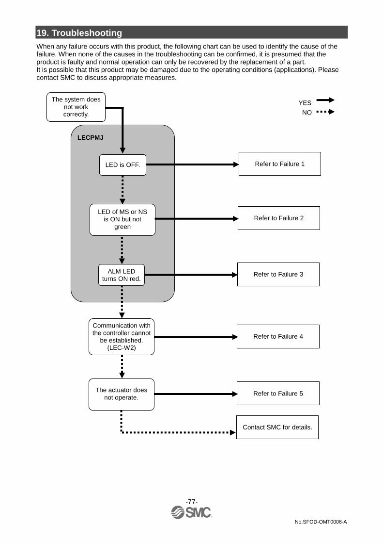
-77-
No.SFOD-OMT0006-A
19. Troubleshooting
When any failure occurs with this product, the following chart can be used to identify the cause of the failure. When none of the causes in the troubleshooting can be confirmed, it is presumed that the product is faulty and normal operation can only be recovered by the replacement of a part. It is possible that this product may be damaged due to the operating conditions (applications). Please contact SMC to discuss appropriate measures.
The system does not work correctly.
LED is OFF. Refer to Failure 1
LED of MS or NS is ON but not
green
Refer to Failure 2
ALM LED turns ON red.
Refer to Failure 3
LECPMJ
The actuator does not operate.
Refer to Failure 5
Contact SMC for details.
Communication with the controller cannot
be established. (LEC-W2)
Refer to Failure 4
YES
NO
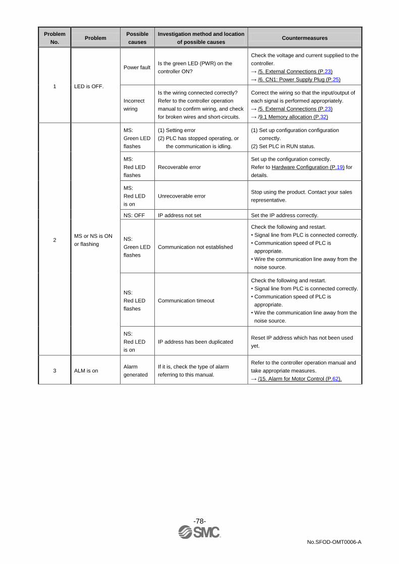
-78-
No.SFOD-OMT0006-A
Problem
No. Problem
Possible
causes
Investigation method and location
of possible causes Countermeasures
1 LED is OFF.
Power fault Is the green LED (PWR) on the
controller ON?
Check the voltage and current supplied to the
controller.
→ /5. External Connections (P.23)
→ /6. CN1: Power Supply Plug (P.25)
Incorrect
wiring
Is the wiring connected correctly?
Refer to the controller operation
manual to confirm wiring, and check
for broken wires and short-circuits.
Correct the wiring so that the input/output of
each signal is performed appropriately.
→ /5. External Connections (P.23)
→ /9.1 Memory allocation (P.32)
2 MS or NS is ON
or flashing
MS:
Green LED
flashes
(1) Setting error
(2) PLC has stopped operating, or
the communication is idling.
(1) Set up configuration configuration
correctly.
(2) Set PLC in RUN status.
MS:
Red LED
flashes
Recoverable error
Set up the configuration correctly.
Refer to Hardware Configuration (P.19) for
details.
MS:
Red LED
is on
Unrecoverable error Stop using the product. Contact your sales
representative.
NS: OFF IP address not set Set the IP address correctly.
NS:
Green LED
flashes
Communication not established
Check the following and restart.
• Signal line from PLC is connected correctly.
• Communication speed of PLC is
appropriate.
• Wire the communication line away from the
noise source.
NS:
Red LED
flashes
Communication timeout
Check the following and restart.
• Signal line from PLC is connected correctly.
• Communication speed of PLC is
appropriate.
• Wire the communication line away from the
noise source.
NS:
Red LED
is on
IP address has been duplicated Reset IP address which has not been used
yet.
3 ALM is on Alarm
generated
If it is, check the type of alarm
referring to this manual.
Refer to the controller operation manual and
take appropriate measures.
→ /15. Alarm for Motor Control (P.62).
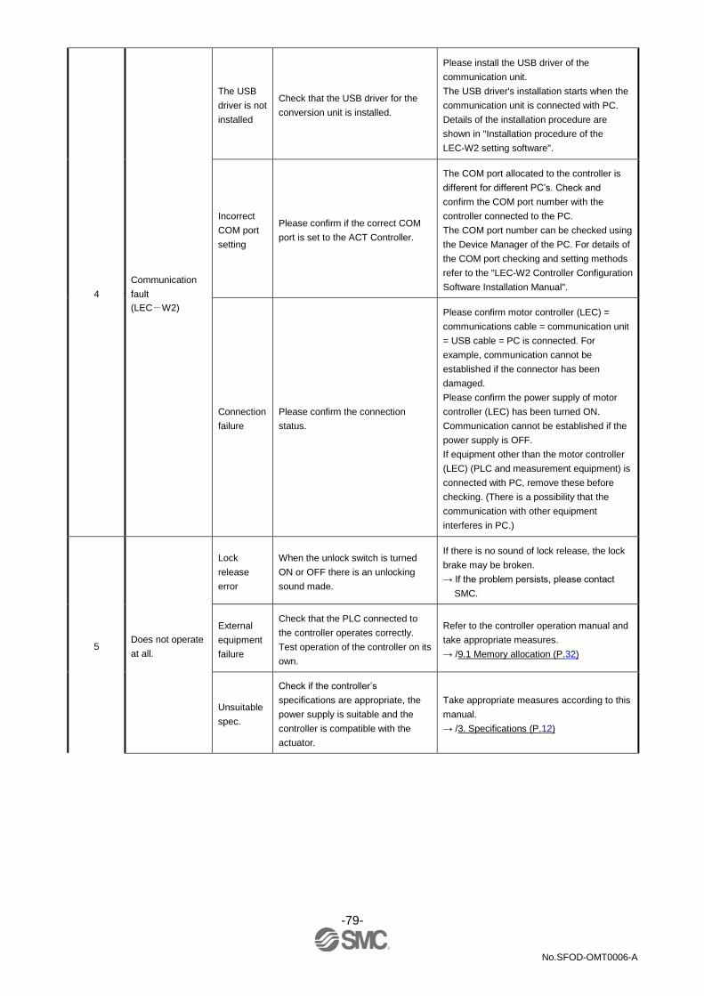
-79-
No.SFOD-OMT0006-A
4
Communication
fault
(LEC-W2)
The USB
driver is not
installed
Check that the USB driver for the
conversion unit is installed.
Please install the USB driver of the
communication unit.
The USB driver's installation starts when the
communication unit is connected with PC.
Details of the installation procedure are
shown in "Installation procedure of the
LEC-W2 setting software".
Incorrect
COM port
setting
Please confirm if the correct COM
port is set to the ACT Controller.
The COM port allocated to the controller is
different for different PC’s. Check and
confirm the COM port number with the
controller connected to the PC.
The COM port number can be checked using
the Device Manager of the PC. For details of
the COM port checking and setting methods
refer to the "LEC-W2 Controller Configuration
Software Installation Manual".
Connection
failure
Please confirm the connection
status.
Please confirm motor controller (LEC) =
communications cable = communication unit
= USB cable = PC is connected. For
example, communication cannot be
established if the connector has been
damaged.
Please confirm the power supply of motor
controller (LEC) has been turned ON.
Communication cannot be established if the
power supply is OFF.
If equipment other than the motor controller
(LEC) (PLC and measurement equipment) is
connected with PC, remove these before
checking. (There is a possibility that the
communication with other equipment
interferes in PC.)
5 Does not operate
at all.
Lock
release
error
When the unlock switch is turned
ON or OFF there is an unlocking
sound made.
If there is no sound of lock release, the lock
brake may be broken.
→ If the problem persists, please contact
SMC.
External
equipment
failure
Check that the PLC connected to
the controller operates correctly.
Test operation of the controller on its
own.
Refer to the controller operation manual and
take appropriate measures.
→ /9.1 Memory allocation (P.32)
Unsuitable
spec.
Check if the controller’s
specifications are appropriate, the
power supply is suitable and the
controller is compatible with the
actuator.
Take appropriate measures according to this
manual.
→ /3. Specifications (P.12)

-80-
No.SFOD-OMT0006-A
5
Operation stops
intermittently
Incorrect
wiring
Is the wiring connected correctly?
Refer to the controller operation
manual to confirm wiring, and check
for broken wires and short-circuits.
Correct the wiring so that the input/output of
each signal is performed appropriately.
→ /5. External Connections (P.23)
→ /9.1 Memory allocation (P.32)
Electric
noise
Connect to Ground correctly.
Avoid bundling the cables.
Refer to the controller operation manual and
take appropriate measures.
→ /3.4 Mounting (P.16)
Incorrect
parameters
Check that the parameter values are
correct.
Also, check the cables are not
bundled.
Take appropriate measures according to this
manual.
→ /10. Settings and Data Entry (P.41)
Voltage
drop
Check for a temporary voltage drop
in the power supply?
(If there is a temporary voltage drop
in the power supply, the EMG
terminal of CN1 power connector will
turn OFF so the actuator will stop.
However, this stop will be released
when the voltage recovers.)
There is a possibility of a momentary voltage
drop because the capacity of the power
supply is insufficient, or if the power supply is
"inrush-current control" type.
If necessary, replace the power supply.
→ /3. Specifications (P.12)
Failure of
pushing
operation.
Check whether the INP output turns
ON during pushing operation.
(If completion of pushing operation
is detected by the INP output, the
PLC cannot confirm the completion
of driving.)
Check the INP output signal before the
energy saving mode is turned ON.
→ /9.1 Memory allocation (P.32)
Unsuitable
spec.
Check if the controller’s specifications
are appropriate, the power supply is
suitable and the controller is
compatible with the actuator.
Take appropriate measures according to this
manual.
→ /3. Specifications (P.12)
Signal
timing
Check the timing of the signal from
the PLC to the controller.
Leave an interval of 15ms or more
(recommendation is 30ms) between input
signals and maintain the state of the signal
for 15ms or more (recommendation is 30ms),
because PLC processing delays and
controller scanning delays can occur.
→ /11.4 Controller input signal response time
(P.49)
The actuator
does not move to
the correct
position.
Incorrect
origin
position
If it is a pushing operation, repeat
return to origin operations several
times to check if the actuator returns to
the origin correctly.
Perform the Return to Origin
position operation several times to
check the Origin position.
Take measures to make the actuator operate
normally (remove foreign matter that
interferes with the actuator movement, etc.)
Delete
Incorrect
parameters
Check that the parameter values are
appropriate and the program is
correct.
Review the maximum speed, the
maximum acceleration and the
maximum deceleration of the actuator.
Modify the parameters and test the operation.
→ /10. Settings and Data Entry (P.41)
Unsuitable
specification
Check if the controller’s
specifications are appropriate, the
power supply is suitable and the
controller is compatible with the
actuator.
Take appropriate measures according to this
manual.
→ /3. Specifications (P.41)

-81-
No.SFOD-OMT0006-A
5
The actuator
does not move
correctly.
Incorrect
wiring
Is the wiring connected correctly?
Refer to the controller operation
manual to confirm wiring, and check
for broken wires and short-circuits.
Correct the wiring so that the input/output of
each signal is performed appropriately.
→ /5. External Connections (P.23)
→ /9.1 Memory allocation (P.32)
Unsuitable
specification
Check if the controller’s
specifications are appropriate, the
power supply is suitable and the
controller is compatible with the
actuator.
Take appropriate measures according to this
manual.
→ /3. Specifications (P.12)
Signal
timing
Check the timing of the signal from
the PLC to the controller.
Leave an interval of 15ms or more
(recommendation is 30 ms) between input
signals and maintain the state of the signal
for 15ms or more (recommendation is 30
ms), because PLC processing delays and
controller scanning delays can occur.
→ /11.4 Controller input signal response time
(P.49)
Data not
stored
correctly
Check whether data (step data,
parameter) is written correctly.
Do not turn OFF the controller input
power or remove the cable while
data is being written (green light
flashing).
Input correct data (step data, parameter) again
and confirm operation.
→ /3.2 Parts Description (P.13)
→ /10. Settings and Data Entry (P.41)
Speed not
achieved
Incorrect
parameters
Check that the parameter values are
correct.
Review the maximum speed and the
maximum acceleration of the
actuator.
Modify the values of the parameters and test
the operation.
→ /10. Settings and Data Entry (P.41)
Operation
pattern is
not suitable.
Check if a trapezoidal
acceleration/deceleration is
programmed for the actuator
operation. In case of such operation,
the actuator may start slowing down
before it reaches the maximum
speed.
Modify the setting to make the moving
distance longer or the acceleration larger.
→ /10. Settings and Data Entry (P.41)
Unsuitable
specification
Check if the controller’s
specifications are appropriate, the
power supply is suitable and the
controller is compatible with the
actuator.
Take appropriate measures according to this
manual.
→ /3. Specifications (P.12)
Voltage
drop
Check for a temporary voltage drop
in the power supply?
(If there is a temporary voltage drop
in the power supply, the EMG
terminal of CN1 power connector
will turn OFF so the actuator will
stop. However, this stop will be
released when the voltage
recovers.)
There is a possibility of a momentary voltage
drop because the capacity of the power
supply is insufficient, or if the power supply is
"inrush-current control" type.
If necessary, replace the power supply.
→ /3. Specifications (P.12)

-82-
No.SFOD-OMT0006-A
20. Definitions and terminology
Term Definition
PLC Abbreviation of Programmable Logic Controller, a digital computer used for automation of electromechanical processes.
Communication speed Data transmission speed of a network such as a Fieldbus network. The speed is determined by upper devices (PLC etc.). The unit is bit per second (bps).
Fieldbus Network protocol to transmit digital signals between automated industrial system such as measurement tool or manipulator and PLC.
Trademark The company name, system name, and product name described in this document are registered trademarks of each individual company. In this document TM and (R) are not specified.

-83-
No.SFOD-OMT0006-A
Revision history
A: Contents are added.
Note: Specifications are subject to change without prior notice and any obligation on the part of the manufacturer. © 2015 SMC Corporation All Rights Reserved