model s-c4 machine code: d067/d068/d069/d072 field service...
TRANSCRIPT

Model S-C4 Machine Code:
D067/D068/D069/D072
FIELD SERVICE MANUAL
January, 2009 Subject to change


Important Safety Notices
Prevention of Physical Injury
1. Be sure that the power cord is unplugged before disassembling or assembling parts of the copier orperipherals.
2. The wall outlet should be near the copier and easily accessible.
3. Note that electrical voltage is supplied to some components of the copier and the paper tray unit evenwhile the main power switch is off.
4. If any adjustment or operation check has to be made with exterior covers off or open while the mainswitch is turned on, keep hands away from electrified or mechanically driven components.
5. If you start a job before the copier completes the warm-up or initializing period, keep hands awayfrom the mechanical and electrical components until job execution has started. The copier will startmaking copies as soon as warm-up or initialization is finished.
6. The inside and the metal parts of the fusing unit become extremely hot while the copier is operating.Be careful to avoid touching those components with your bare hands.
Health Safety Conditions
Toner and developer are nontoxic, but getting either of these into your eyes may cause temporary eyediscomfort. Try to remove with eye drops or flush with water. If material remains in eye or if discomfortcontinues, get medical attention.
Observance of Electrical Safety Standards
The copier and its peripherals must be installed and maintained by a customer service representative whohas completed the training course on those relevant models.
• Keep the machine away from flammable liquids, gases, and aerosols. A fire or an explosion mightoccur if this precaution is not observed.
Lithium Batteries
Incorrect replacement of lithium battery(s) on the FCU, controller board and memory board unit may poserisk of explosion. Replace only with the same type or with an equivalent type recommended by themanufacturer. Discard used batteries in accordance with the manufacturer's instructions.
1

Safe and Ecological Disposal
1. Do not incinerate toner bottles or used toner. Toner dust may ignite suddenly if exposed to an openflame.
2. Dispose of used toner, developer, and organic photoconductors in accordance with local regulations.(These are nontoxic supplies.)
3. Dispose of replaced parts in accordance with local regulations.
4. When keeping used lithium batteries in order to dispose of them later, do not put more than 100batteries per sealed box. Storing larger numbers or not sealing them apart may lead to chemicalreactions and heat build-up.
Laser Safety
The Center for Devices and Radiological Health (CDRH) prohibits the repair of laser-based optical unitsin the field. The optical housing unit can only be repaired in a factory or at a location with the requisiteequipment. The laser subsystem is replaceable in the field by a qualified Customer Engineer. The laserchassis is not repairable in the field. Customer engineers are therefore directed to return all chassis andlaser subsystems to the factory or service depot when replacement of the optical subsystem is required.
• Use of controls not specified in this manual, or performance of adjustments or procedures not specifiedin this manual, may result in hazardous radiation exposure.
WARNING FOR LASER UNIT
• Turn off the main switch before attempting any of the procedures in the Laser Unit section. Laserbeams can seriously damage your eyes.
CAUTION MARKING:
2

Symbols and AbbreviationsThis manual uses several symbols and abbreviations. The meaning of those symbols and abbreviations isas follows:
See or Refer to
Clip ring
E-ring
Screw
Connector
Clamp
SEF Short Edge Feed
LEF Long Edge Feed
- Core Technology manual
Cautions, Notes, etc.
The following headings provide special information:
• Failure to obey warning information could result in serious injury or death.
• Obey these guidelines to ensure safe operation and prevent minor injuries.
• This information provides tips and advice about how to best service the machine.
3

TABLE OF CONTENTSImportant Safety Notices...................................................................................................................................1
Prevention of Physical Injury..........................................................................................................................1
Health Safety Conditions...............................................................................................................................1
Observance of Electrical Safety Standards.................................................................................................1
Lithium Batteries..............................................................................................................................................1
Safe and Ecological Disposal.......................................................................................................................2
Laser Safety.....................................................................................................................................................2
Symbols and Abbreviations...............................................................................................................................3
1. Product Information
Specifications....................................................................................................................................................11
Machine Configuration....................................................................................................................................12
Mainframe (Basic: D067/D072)..............................................................................................................12
Mainframe (F/SPF: D068/D069).............................................................................................................13
System Components (For D068/D069)...................................................................................................14
Overview..........................................................................................................................................................16
Component Layout.......................................................................................................................................16
Electrical Components.................................................................................................................................18
Paper Path....................................................................................................................................................21
Drive Layout..................................................................................................................................................22
Guidance for Those Who are Familiar with Predecessor Products..............................................................24
2. Installation
Installation Cautions.........................................................................................................................................25
Installation Requirements.................................................................................................................................26
Environment..................................................................................................................................................26
Machine Level..............................................................................................................................................26
Minimum Operational Space Requirements.............................................................................................27
Power Requirements....................................................................................................................................28
Copier...............................................................................................................................................................29
Accessory Check..........................................................................................................................................29
Optional Handset (Only for D068/D069)..............................................................................................36
Paper Tray Unit.................................................................................................................................................39
Accessory Check..........................................................................................................................................39
Installation Procedure..................................................................................................................................39
4

Paper Tray Unit Heater....................................................................................................................................42
Accessory Check..........................................................................................................................................42
Installation Procedure..................................................................................................................................43
ARDF (B872)....................................................................................................................................................50
Accessory Check..........................................................................................................................................50
Installation Procedure..................................................................................................................................50
USB 2.0/SD Slot Type B.................................................................................................................................57
Accessory Check..........................................................................................................................................57
Installation Procedure..................................................................................................................................57
Testing the SD Card/USB Slot....................................................................................................................63
Optional Paper Tray Grip Handle..................................................................................................................65
Accessories...................................................................................................................................................65
Printer/Scanner Unit........................................................................................................................................67
Accessory Check..........................................................................................................................................67
Installation Procedure..................................................................................................................................68
Controller Options............................................................................................................................................73
Overview......................................................................................................................................................73
PostScript3 Installation................................................................................................................................73
Wireless LAN (IEEE 802.11a/g) Installation...........................................................................................74
IEEE 1284 Installation.................................................................................................................................76
VM Card Type L (D467).............................................................................................................................77
Gigabit Ethernet...........................................................................................................................................78
HDD Option (D467, only for D067/D068)............................................................................................79
DataOverwriteSecurity Unit Type I (D362)...............................................................................................81
HDD Encryption Unit (D377)......................................................................................................................84
3. Preventive Maintenance
Maintenance Tables........................................................................................................................................89
How to Clear the PM Counter.........................................................................................................................90
4. Replacement and Adjustment
Precautions........................................................................................................................................................91
General.........................................................................................................................................................91
Lithium Batteries............................................................................................................................................91
Halogen-free Cable....................................................................................................................................91
5

Special Tools and Lubricants...........................................................................................................................92
Exterior Covers and Operation Panel............................................................................................................93
Rear Cover...................................................................................................................................................93
Copy Tray.....................................................................................................................................................93
Scale Plate (D067 only)..............................................................................................................................94
Operation Panel and Upper Covers..........................................................................................................95
Right Door.....................................................................................................................................................96
Bypass Tray..................................................................................................................................................96
Platen Cover Sensor....................................................................................................................................97
Scanner Unit.....................................................................................................................................................98
Exposure Glass............................................................................................................................................98
Lens Block.....................................................................................................................................................99
Exposure Lamp, Lamp Stabilizer Board.....................................................................................................99
Scanner Motor...........................................................................................................................................100
Scanner HP Sensor....................................................................................................................................102
Scanner Alignment Adjustment.................................................................................................................102
Fusing..............................................................................................................................................................104
Fusing Unit..................................................................................................................................................104
Exit Sensor..................................................................................................................................................105
Hot Roller Stripper Pawls..........................................................................................................................105
Hot Roller and Fusing Lamp......................................................................................................................106
Thermoswitches and Thermistor...............................................................................................................108
Pressure Roller............................................................................................................................................109
Checking the NIP band.............................................................................................................................110
PCU and Quenching Lamp...........................................................................................................................111
PCU.............................................................................................................................................................111
Quenching Lamp.......................................................................................................................................112
Exhaust Fan and Main Motor.......................................................................................................................113
Exhaust Fan................................................................................................................................................113
Main Motor...............................................................................................................................................114
Paper Feed.....................................................................................................................................................115
Paper Feed Roller and Friction Pad.........................................................................................................115
Paper End Sensor......................................................................................................................................116
6

Registration Sensor....................................................................................................................................116
Bypass Paper End Sensor.........................................................................................................................117
Bypass Feed Roller....................................................................................................................................118
Bypass Feed Clutch and Friction Pad......................................................................................................119
Paper Feed and Registration Clutches.....................................................................................................120
Image Transfer...............................................................................................................................................122
Transfer Roller............................................................................................................................................122
ID Sensor and Duplex Roller....................................................................................................................123
Discharge plate.........................................................................................................................................124
BICU and Controller Board..........................................................................................................................125
BICU...........................................................................................................................................................125
Controller Board (F/SPF models: D068/D069)...................................................................................127
Other Replacements......................................................................................................................................132
Duplex Motor............................................................................................................................................132
High-Voltage Power Supply Board ........................................................................................................133
PSU.............................................................................................................................................................134
Contact-Release Solenoid........................................................................................................................135
Toner Supply Clutch..................................................................................................................................135
FCU (For D068/D069)...........................................................................................................................136
Laser Unit........................................................................................................................................................139
Location of the Caution Decal..................................................................................................................139
Laser Unit....................................................................................................................................................139
LD Unit and Polygon Mirror Motor..........................................................................................................140
ARDF...............................................................................................................................................................141
ARDF...........................................................................................................................................................141
DF Rear Cover...........................................................................................................................................142
Original Feed Unit.....................................................................................................................................142
Separation Roller.......................................................................................................................................143
DF Drive Board..........................................................................................................................................143
Original Set and DF Inverter Sensor........................................................................................................144
DF Registration and DF Exit Sensor..........................................................................................................145
DF Feed Motor..........................................................................................................................................146
DF Transport Motor...................................................................................................................................147
7

DF Feed Clutch..........................................................................................................................................148
Adjusting Copy Image Area.........................................................................................................................149
Printing........................................................................................................................................................149
Scanning....................................................................................................................................................151
DF Image Adjustment................................................................................................................................154
5. Troubleshooting
Service Call Conditions.................................................................................................................................157
Electrical Component Defects.......................................................................................................................158
Card Save Function.......................................................................................................................................159
Overview....................................................................................................................................................159
Procedure...................................................................................................................................................159
Fax Troubleshooting Guide (Only For D068/D069)................................................................................162
6. System Maintenance Reference
Service Program.............................................................................................................................................163
SP Tables....................................................................................................................................................163
Using SP and SSP Modes.........................................................................................................................163
Using SP Mode (F/SPF: D068/D069).......................................................................................................166
NVRAM Data Upload/Download..........................................................................................................166
Firmware Update Procedure....................................................................................................................167
Test Pattern Print (SP5-902-001).............................................................................................................172
Memory Clear...........................................................................................................................................175
Machine No. Setting (SP5-811-001).....................................................................................................176
SMC Print (SP5-990)................................................................................................................................177
ID Sensor Error Analysis (SP2-221)........................................................................................................177
Using SP Mode (Basic: D067/D072)........................................................................................................179
NVRAM Data Upload/Download (SP5-824/825).............................................................................179
Firmware Update Procedure....................................................................................................................180
Test Pattern Print (SP5-902-001).............................................................................................................181
SMC Print (SP5-990)................................................................................................................................184
Serial Number Input (SP5-811-001)......................................................................................................184
Memory Clear...........................................................................................................................................185
ID Sensor Error Analysis (SP2-221)........................................................................................................186
Fax Service Tables (Only For D068/D069)..............................................................................................188
8

INDEX...........................................................................................................................................................189
9

10

1. Product Information
SpecificationsSee "Appendices" for the following information:
• General Specifications
• Supported Paper Sizes
11
1

Machine Configuration
Mainframe (Basic: D067/D072)
Standard Component Machine Code Remarks
1 Copier [A] D067/D072 -
Optional Components Machine Code Remarks
2 500-Sheet Paper Feed Unit [B] B421 Two can be used.
Standard/Optional Component Machine Code Remarks
3 ARDF [C] B872• Standard for D072
• Optional for basic
1. Product Information
12
1

Mainframe (F/SPF: D068/D069)
Standard Component Machine Code Remarks
1 Copier [A] D068/D069 -
2 GW Controller Board [C] - -
3 ARDF [D] B872 -
4 Fax Unit [E] - -
Optional Components Machine Code Remarks
5 500-sheet Paper Feed Unit [B] B421 Two can be used.
6 Handset [F] B433 NA only
Machine Configuration
13
1

System Components (For D068/D069)
Item Machine Code Remarks
Controller Box - [A] Standard
USB2.0/SD Slot D467 [B] Option only for D069
Printer/Scanner unit D468 [C]SD card for the Printer/Scanner Unit
Standard only for D069
HDD Encryption Unit D377 [C]
One from the threePostScript 3 D468 [C]
Data Overwrite SecurityUnit
D362 [C]
VM Card D467 [D] -
IEEE 1284 B679 [E]
One from the fourWireless LAN M344 [E]
Gigabit Ethernet Board G874 [E]
1. Product Information
14
1

RAM DIMM G332 [F] Distributed with the printer/scanner unit
HDD D362 [G] -
Machine Configuration
15
1

Overview
Component Layout
Mainframe
1. Exposure Lamp 20. ID (Image Density) Sensor
2. 1st Scanner 21. Registration Roller
3. CCD (on SBU) 22. Registration Sensor
4. Lens Block 23. Bypass Tray
5. 2nd Scanner 24. Bypass Paper Feed Roller
6. 2nd Mirror 25. Bypass Paper End Sensor
7. 3rd Mirror 26. Bypass Friction Pad
1. Product Information
16
1

8. Platen Cover Sensor 27. Mixing Augers
9. Exposure Glass 28. (Main) Friction Pad
10. Exit Roller 29. Paper Feed Roller
11. Exit Sensor 30. Paper End Sensor
12. Scanner Motor 31. TD (Toner Density) Sensor
13. Hot Roller 32. Bottom Plate
14. Pressure Roller 33. Polygon Mirror Motor
15. Cleaning Blade 34. Laser Unit
16. OPC Drum 35. Toner Supply Bottle (or THM)
17. Discharge Plate 36. Toner Collection Coil
18. Transfer Roller 37. Scanner HP Sensor
19. Development Roller
ARDF
1. Separation Roller 7. Exit Roller
2. Paper Feed Roller 8. Exit Sensor
3. Pick-up Roller 9. Registration Sensor
4. Original Set Sensor 10. Registration Roller
5. Inverter Roller 11. Inverter Sensor
Overview
17
1

6. Junction Gate 12. Transport Roller
Electrical Components
Electrical Components 1
1. Lens Block 11. ID (Image Density) Sensor
2. Exposure Lamp 12. Registration Sensor
3. Lamp Stabilizer Board 13. Paper End Sensor
4. Scanner HP Sensor 14. Toner Density Sensor
5. Platen Cover Sensor 15. Bypass Paper End Sensor
1. Product Information
18
1

6. Scanner Motor 16. Right Door Safety Switch
7. Mechanical Counter 17. Front Door Safety Switch
8. Polygon Mirror Motor 18. Quenching Lamp
9. LD Unit 19. High-Voltage Power Supply Board
10. Exit Sensor 20. Operation Panel Board
Electrical Components 2
1. Duplex Motor 7. Paper Feed Clutch
2. Exhaust Fan 8. Toner Supply Clutch
3. PSU 9. Bypass Feed Clutch
4. Controller Board (GW) 10. Registration Clutch
5. BICU 11. Fusing Solenoid
6. Main Motor
Overview
19
1

ARDF
1. DF Feed Clutch 6. DF Feed Motor
2. Registration Sensor 7. Inverter Sensor
3. Exit Sensor 8. DF Drive Board
4. Left Cover Sensor 9. Junction Gate Solenoid
5. DF Transport Motor 10. Original Set Sensor
1. Product Information
20
1

Paper Path
1. Original Registration Sensor (Document Feeder)
2. Exit Senor (Document Feeder)
3. Inverter Sensor (Document Feeder)
4. Original Set Sensor (Document Feeder)
5. Exit Sensor
6. Paper Path Sensor
7. Registration Sensor
8. By-pass Paper End Sensor
9. Paper Feed Sensor (Optional Tray)
Overview
21
1

10. Paper End Sensor (Optional Tray)
11. Paper End Sensor
Drive Layout
Mainframe
1. Scanner Motor 7. Bypass Feed Clutch (By-pass Tray)
2. Duplex motor 8. Registration Clutch
3. Exit Roller 9. Developer Driver Gear
4. Toner Bottle Clutch 10. Drum Drive Gear
5. Main Motor 11. One-way Gear (Duplex Unit)
6. Paper Feed Clutch 12. Fusing Drive Gear
1. Product Information
22
1

ARDF
1. DF Feed Motor
2. Feed Roller
3. Pick-up Roller
4. Inverter Roller
5. DF Feed Clutch
6. Separation Roller
7. Transport Roller
8. DF Transport Motor
9. Exit Roller
10. Registration Roller
• DF Feed Motor: Drives the feed, separation, pick-up, and transport and inverter rollers.
• DF Transport Motor: Drives the registration and exit rollers.
Overview
23
1

Guidance for Those Who are Familiar withPredecessor ProductsThe D067/D068/D069/D072 range of machines is the successor model to the B262/B292/B284/B288 range of machines. If you have experience with the predecessor line, the following information maybe of help when you read this manual.
Differences from Predecessor Products
D067/D068/D069/D072 B262/B292/B284/B288
Controller Option
Following controller options wereadded.
• HDD (80GB)
• USB2.0/SD Slot
• Gigabit Ethernet
-
SD Card Slots 2 slots 3 slots
Copying Speed17ppm: Memory copy
16ppm: ADF 1 to 116ppm
1. Product Information
24
1

2. Installation
Installation Cautions
• Before installing an optional unit, do the following:
• Print out all messages stored in the memory, all user-programmed items, and a system parameter list.
• If there is a printer option on the machine, print out all data in the printer buffer.
• Turn off the main switch and disconnect the power cord, the telephone line, and the network cable.
25
2

Installation Requirements
Environment
–Temperature and Humidity Chart–
• Temperature Range: 10°C to 32°C (50°F to 89.6°F)
• Humidity Range: 15% to 80% RH
• Ambient Illumination: Less than 1,500 lux (Do not expose to direct sunlight.)
• Ventilation: Room air should turn over at least 3 times/hr/person
• Ambient Dust: Less than 0.1 mg/m3
• Do not install the machine where it will be exposed to direct sunlight or to direct airflow (from a fan,air conditioner, air cleaner, etc.).
• Do not install the machine where it will be exposed to corrosive gas.
• Place the machine on a firm and level base.
• Do not install the machine where it may be subjected to strong vibration.
Machine Level
Front to back: Within 5 mm (0.2") of level
2. Installation
26
2

Right to left: Within 5 mm (0.2") of level
Minimum Operational Space Requirements
Place the machine near the power source, providing clearance as shown.
A: Front – 750 mm (29.6")B: Left – 100 mm (3.9")C: Rear – 100 mm (3.9")D: Right – 100 mm (3.9")
E: Depth – 450 mm (17.7")
F: Width – 485 mm (19.1")
• The 750-mm front space indicated above is sufficient to allow the paper tray to be pulled out.Additional space is required to allow an operator to stand at the front of the machine.
Installation Requirements
27
2

• Actual minimum space requirement for left, rear, and right sides is 10mm (0.4") each, but note thatthis will not allow room for opening of the bypass tray, right door, platen cover, or ARDF unit.
Power Requirements
• Make sure that the wall outlet is near the machine and easily accessible. After completing installation,make sure the plug fits firmly into the outlet.
• Avoid multiple connections to the same power outlet.
• Be sure to ground the machine.
Input voltage:
North America: 110 – 120 V, 60 Hz, 8 A
Europe: 220 – 240 V, 50/60 Hz, 4 A
Image quality guaranteed at rated voltage ± 10%.
Operation guaranteed at rated voltage ± 15%.
2. Installation
28
2

Copier
Accessory Check
Basic Model (D067/D072)
Description Q’ty
NECR (-15, -27) 1
EU Safety Sheet (-27) 1
Paper Size Decal (-15, -27) 1
Operating Instructions – Book: Fax (-15, -27) 1 set
Operating Instructions – Book (-15, -27) 1 set
Operating Instructions – CD ROM (-15, -27) 1 set
EMC caution Sheet (-27) 1
Fax Model (D068)/ Printer/Scanner and Fax Model (D069)
Description Q’ty
NECR (-17) 1
EU Safety Sheet (-27) 1
Paper Size Decal (-17, -27, -29) 1
Operating Instructions – Book (-17, -27, -29) 1 set
Operating Instructions – CD ROM (-17, -27, -29) 1 set
Handset Bracket (-17) 1
Screw for Handset Bracket (-17) 2
Modular Cable (-17) 1
Operating Instructions – Book: Fax (-17, -27, -29) 1 set
Copier
29
2
Description Q’ty
Connecter Cover for TEL (-17) 1
Ferrite Core for TEL Line 1
Ferrite Core (-17, -27, -29) 1
EMC Caution Sheet (-27) 1
EULA Sheet (-17, -27, -29) 1
Caution Decal (-17, -27, -29) 1
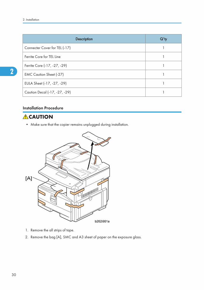
Installation Procedure
• Make sure that the copier remains unplugged during installation.
1. Remove the all strips of tape.
2. Remove the bag [A], SMC and A3 sheet of paper on the exposure glass.
2. Installation
30
2

3. Remove the spacing wedge [B].
4. Remove the three scanner lock pins. (A tag is hanging from each pin.) To remove: Grasp the base ofthe pin [C], turn the pin 90 degrees, and pull it down and out.
5. Remove the tags from the pins.
6. Break each pin off the base [C].
7. Discard the pin part [D].
8. Set each base [C] back into its original hole, turning it 90° to lock it into place. (Be sure to do this forall three pins.)
Copier
31
2

9. Open the front door [E].
10. Lift lever [F], press in on latch [G] and pull the bottle holder [H] out. (You do not need to pull it completelyout of the machine.)
11. Take a new bottle of toner, and shake it several times.
12. Remove the outer cap [I].
• Do not remove the inner cap [J].
13. Load the bottle on the holder.
• Do not forcefully turn the toner bottle on the holder. After you turn on the main power switch, thecopier sets the bottle in place.
14. Push the bottle holder back into the machine.
15. Press the latch [K] down to lock the holder.
2. Installation
32
2

16. Remove the padding [L].
17. Pull each tabbed strip [M] out of the PCU with one hand, supporting the PCU with the other.
• Do not pull both strips at the same time, as this could damage the PCU.
18. Close the front door.
19. Pull out the paper tray, and remove the tape securing the end fence in the compartment.
20. Push the bottom plate down, and then load the paper.
21. Adjust the side fences. If you load paper shorter than A4, set the end fence in the correct position.
Copier
33
2

22. Push the tray back into the copier.
23. Attach the appropriate Brand Decal to the center [N] of the front door if necessary.
24. Attach the appropriate tray number decal and paper-size decal to the paper tray [O].
25. Install optional units (if any).
26. Attach the ferrite core [P] to the network cable when connecting the cable.
27. Attach the ferrite core to the telephone line in the same manner as step 26 (only for D068/D069).
28. Connect the telephone line to the "LINE" jack (only for D068/D069).
• The end of the ferrite core must be about 10 cm (4") from the end of the cable.
29. Plug in the machine and turn on the main power switch.
2. Installation
34
2

30. Select the language used in the operation panel as necessary ( > Language).
For D068/D069: Interface settings
D068:
1. Start the SP mode.
2. Select SP5-985-001 (NIC setting) and change the setting value to "0" (OFF).
3. Select SP5-985-002 (USB setting) and change the setting value to "0" (OFF).
4. Turn the main switch off and on.
D069:
1. Start the SP mode.
2. Select SP5-985-001 (NIC setting) and change the setting value to "1" (ON).
3. Select SP5-985-002 (USB setting) and change the setting value to "1" (ON).
4. Turn the main switch off and on.
For D068/D069: Copier settings
1. Start the SP mode.
2. Select SP5-801-001 and execute the initialization.
3. Exit the SP mode, and then start the UP mode.
4. Select the "@Remote Service" ("User Tool" > "System Settings > Administrator Tools" > "ExtendedSecurity" > @Remote Service") and select "Prohibit".
5. Exit the UP mode, and then start the SP mode.
6. Select SP5-870-003 and execute initialization for @Remote.
7. Select SP5-907-001 and specify the "Plug & Play".
8. Select SP5-870-001 and execute writing certification for @Remote S.
9. Select SP5-302-002 and specify the time zone.
10. Select SP5-307-001, 003, and 004 and specify the daylight-saving-time settings.
11. Exit the SP mode and turn the main switch off and on.
12. Start the UP mode.
13. Specify the date and time with "Set Date" or "Set Time" (User Tool" > "System Settings" > "Set Date"or "Set Time").
14. Turn the main switch off and on.
15. Check the operations.
Copier
35
2

16. Make a full size copy, and check if the side-to-side and leading edge registrations are correct. If theyare not, adjust the registrations.
For D068/D069: Fax Settings
Initializing the Fax unit
When you press the Fax key for the first time after installation, the error "SRAM problem occurred / SRAMwas formatted" will show on the LCD for initializing the program of the fax unit. Turn the main power switchoff/on to clear the error display.
• If another error occurs after initialization, this can be a functional problem.
1. Select fax SP1-101-016 and specify the country code.
2. Select fax SP3-101-001 and specify the service station.
Optional Handset (Only for D068/D069)
Accessory Check
Check that you have the components and accessories.
No. Description Q’ty
1 Handset 1
2 Handset cradle 1
3 Screws 2
4 Handset manual 1
• The handset bracket is not included in the optional handset kit. The bracket is provided as an accessoryof the copier.
2. Installation
36
2

Installation Procedure
1. Attach the handset bracket [A] ( x 2)
2. Remove the label from the handset cradle [B].
3. Attach the cradle [B] to the handset bracket ( x 2).
4. Attach the cradle to the bracket ( x 2).
5. Reattach the label.
Copier
37
2

• The bracket is an accessory of the copier.
6. Set the handset on the cradle.
7. Connect the handset cable to the “TEL” jack and set the telephone cable [A] as shown above.
2. Installation
38
2

Paper Tray Unit
Accessory Check
Confirm that you have these accessories.
Description Q’ty
1. Paper-size decals 1 sheet
2. Installation Procedure (for service technicians) 1
3. Installation Procedure (for users) 1
Installation Procedure
• Unplug the main machine's power cord before starting the following procedure.
1. Remove the tape at [A], and the tape and cardboard at [B].
2. Pull the paper tray part way out of the unit, remove the tape and cardboard at [C], and push the trayback in.
Paper Tray Unit
39
2

3. Set the machine on the paper tray unit.
• When installing a second paper tray unit, place on the first paper tray unit before placing thecopier onto the pair pf paper tray units
4. Remove the paper(s) tray from the paper tray unit(s).
5. Load paper into the paper tray(s). Adjust the side and end fences as necessary. If loading 81/2"x14" paper, remove the end fence and set it into the special compartment.
6. Set the paper tray(s) back into the paper tray unit(s).
2. Installation
40
2

7. Stick on the appropriate tray-number decal(s) and paper-size decal(s), at the locations indicated inthe illustration.
Paper Tray Unit
41
2

Paper Tray Unit HeaterThe paper tray unit heater is installed only for the first paper tray unit.
Accessory Check
Confirm that you have the accessories listed below.
Description Q’ty
1. Grounding wire 1
2. Relay harness 1
3. Clamps 2
4. Ferrite core 1
5. Heater fastening screws 2
6. PTU fastening screws 3
7. Grounding screw 1
8. Decal for copier 1
9. Decal for paper tray unit 1
10. Tie wrap 1
2. Installation
42
2

Installation Procedure
• Unplug the main machine's power cord before starting the following procedure.
1. Remove the paper tray unit from the copier if it is already installed.
2. Remove the paper trays from the copier and from the paper tray unit.
Paper Tray Unit Heater
43
2

3. Remove the ground screw [1] at the rear of the paper tray unit.
4. Fasten the heater [2] and the supplied ground wire [3] to the paper tray unit ( x 3). Note that [1] isthe ground screw you removed in the previous step and [4] and [5] are the two supplied heaterfastening screws.
• Be sure to position the ground wire [3] and heater harness [6] so that they are out of the way ofthe copier when you set it on the paper tray unit.
5. Set the copier on the paper tray unit.
6. Screw the paper tray unit into place using three supplied PTU fastening screws.
2. Installation
44
2

7. Open the front door and remove the copy tray [7] ( ×1).
8. Close the front door.
1. Open the right cover
2. Remove the interface cover [8] ( x 1).
3. Remove the rear cover [9] ( x 5).
Paper Tray Unit Heater
45
2

4. For D068/D069: Remove the upper left cover [10].
5. For D068/D069: Remove the controller box [11] ( x 1, x 6).
6. Remove the support bracket [12] ( x 3).
2. Installation
46
2

7. Pass the heater harness through the hole [15] at the rear of the copier.
8. Pass relay harness [16] through the opening [17] (at the rear of the PSU) and through the otheropening [15].
9. Connect the relay harness to the heater's harness [18].
10. Pull the relay harness back into the copier.
Paper Tray Unit Heater
47
2

11. Attach the ferrite core [19] over the relay harness.
12. Push the ferrite core back so that it is over the heater's harness.
13. Wrap the heater's harness once around the ferrite core [20].
14. Locate the ferrite core at the rear [24] of the copier behind the rear clamps.
15. Secure the ferrite core with the supplied tie wrap [21].
16. Clip off the excess length of the tie wrap.
17. Connect the relay harness connector [22] to the large connector at the front center of the PSU.
18. Screw the ground wire [23] to the PSU bracket with the included grounding screw.
19. Attach the clamps [24] to the PSU bracket.
20. Attach the heater harness though the clamps.
21. Position the harness so that the front clamp is between the two bindings [25] on the harness.
22. Fasten the clamps.
23. Pull the excess length of the heater's harness out the opening at the rear.
• Be sure that the harness passes on the side of the grounding plate at the bottom of the opening.(The front of the grounding plate must remain clear.)
24. Arrange the excess harness length so that it sits beneath the FCU cover plate.
25. Attach the caution decals to the locations shown in the illustration.
2. Installation
48
2

26. Reassemble the copier.
27. Plug in the power cord, and check the operation.
Paper Tray Unit Heater
49
2

ARDF (B872)This procedure explains how to install the ARDF for the Basic model: D067.
Accessory Check
Description Q’ty
1. Stud Screw 1
2. Screw 1
3. Clamp 1
4. DF Exposure Glass with Mylar 1
5. Left Scale Guide 1
-. Platen Sheet 1
-. Installation Procedure 1
Installation Procedure
• Unplug the main machine's power cord before starting the following procedure.
2. Installation
50
2

1. Unpack the ARDF and remove the packing tape from the bottom of the ARDF body.
2. Open the right door [A].
3. Remove the interface cover [B] ( x 1) and rear cover [C] ( x 5).
ARDF (B872)
51
2

4. Remove the left guide [D] ( x 2) and scanner left cover [E] (hook x 2).
5. Place the DF exposure glass [F] on the glass holder.
• When installing the DF exposure glass, make sure that the side of the DF exposure glass withtwo black points faces down.
• Do not hold the Mylar strip when installing the DF exposure glass.
• Make sure that there is no gap between the two Mylar strips and the scanner frame. If there isany gap between them, dust may fall into the scanner unit.
2. Installation
52
2

6. Peel off the backing [G] of the double-sided tape attached to the rear side of the left scale guide [H],then install it ( x 2 removed in step 4).
7. Remove the two platen stays [I] and bracket ( x 1 each).
8. The bracket is attached to the platen stay of the rear left side. Make sure to remove the bracket at thistime.
ARDF (B872)
53
2

9. Mount the DF [J] on the copier as shown.
10. Secure the screw [K].
11. Attach the clamp [L].
12. Connect two I/F cables [M] to CN109 and CN110 on the BICU, and secure the ground cable [N]( x 1, x 2).
• Make sure that the I/F cable of ARDF is clamped between the two binds [O].
• Reinstall the scanner left side cover removed in step 4.
2. Installation
54
2

13. Cut the cutout [P] with nippers.
14. Reinstall the rear cover and connector cover ( x 6).
15. Close the right door.
16. Open the ARDF.
17. Place platen sheet [Q] on the exposure glass.
18. Line up the rear left corner of the platen sheet flush against corner [R] on the exposure glass.
19. Close the ARDF.
ARDF (B872)
55
2

20. Check that the groove [S] of the ARDF is aligned with the groove [T] of the left scale on the scanner.
• The difference in position between [S] and [T] must be within ± 0.5 mm.
21. Reinstall the platen sheet if both grooves are not aligned correctly.
22. Plug in and turn on the main power switch.
23. Check the ARDF operation.
24. Make a full size copy. Then check to make sure the side-to-side and leading edge registrations arecorrect. If they are not, adjust the side-to-side and leading edge registration (refer to "DF ImageAdjustment" in the section "Replacement and Adjustment").
2. Installation
56
2

USB 2.0/SD Slot Type BThis procedure explains how to install the USB 2.0/SD Slot for the SPF model (D069).
Accessory Check
Check the quantity and condition of the accessories against the following list.
No. Description Q’ty
1 USB2.0/SD Slot 1
2 Ground Plate 1
3 USB Cable 1
4 Screw: M3 x 6 blue 1
5 Screw: M3 x 8 2
6 Screw: 1
7 Clamp 1
8 Decal 1
Installation Procedure
1. Remove the USB connect cover [A].
USB 2.0/SD Slot Type B
57
2

2. Remove the interface cover [A].
3. Open the right door [A].
4. Rear cover [B] ( x 5)
5. Remove the upper left cover [A] as shown above.
2. Installation
58
2

6. Make three holes in the upper left cover with a screwdriver as shown above.
• Smooth the three holes in the upper left cover.
7. Attach the ground plate [A].
8. Secure the USB2.0/SD Slot [B] with the upper left cover as shown above ( x 1: M3 x 6 blue, x2: M3 x 8).
USB 2.0/SD Slot Type B
59
2

9. Make a clamp hole the upper left cover with a screwdriver as shown above.
• Smooth the hole in the upper left cover.
10. Attach the upper left cover [A] to the mainframe.
11. Attach the rear cover.
12. Attach the cable clamp [A] to the upper left cover ( x 1) as shown above.
2. Installation
60
2

13. Connect the USB cable [A] to USB-A.
14. Attach the interface cover.
15. Plug in and turn on the main machine.
16. Enter the SP mode, and then change the setting of SP1013-001 from “0” to “1”.
17. Attach the decal [A] to the USB2.0/SD Slot as shown above.
When Installing the Handset
1. Do steps 1 to 8 in “installation procedure”.
USB 2.0/SD Slot Type B
61
2

2. Make two holes the upper left cover with a screwdriver as shown above.
• Smooth the holes in the upper left cover.
3. Attach the handset bracket [A] ( x 2)
4. Attach the cradle [B] to the handset bracket ( x 2)
2. Installation
62
2

5. Set the handset on the handset bracket.
6. Connect the handset cable to the “TEL” jack and set the telephone cable [A] as shown above.
7. Do steps 13 to 17 in “installation procedure”.
Testing the SD Card/USB Slot
1. Insert an SD card or USB memory device in the slot.
You can connect only one removable memory device at a time.
2. Close the media slot cover.
If you leave the cover open, static electricity conducted through an inserted SD card could cause themachine to malfunction.
3. Make sure that no previous settings remain.
If a previous setting remains, press the [Clear Modes] key.
4. Place an original on the exposure glass.
5. Press [Store File].
6. Press [Store to Memory Device].
7. Press [OK].
8. Press the [Start] key.
When writing is complete, a confirmation message appears.
9. Press [Exit].
USB 2.0/SD Slot Type B
63
2

10. Remove the memory device from the media slot.
Do not remove the memory device while writing is in process.
2. Installation
64
2

Optional Paper Tray Grip HandleThe following procedure is for the paper tray for the main copier or optional paper tray unit.
Accessories
Check the accessories and their quantities against the table below.
No. Description Q’ty
1 Grip Handle 1
2 Screw (M3 x 10) 2
Optional Paper Tray Grip Handle
65
2

Installation Procedure
1. Remove the paper tray [A] from the main copier.
2. Turn the paper tray over to the opposite side.
3. Lower the paper tray grip handle [B] into the paper tray slot as shown, with the arrow in the aboveillustration.
4. Attach the grip handle to the paper tray ( x 2).
• When attaching auxiliary handle (two screws attached from bottom), hold handle against frontof paper drawer (as screws are tightened) to ensure there is ensure the smallest gap betweenback of handle and front of paper drawer.
5. Put the paper tray back into the machine.
2. Installation
66
2

Printer/Scanner UnitThis procedure explains how to install the printer/Scanner unit for the basic models (D067/D072).
Accessory Check
No. Description Q’ty
1 Screw M3 x 6 7
2 Controller Box 1
3 Printer Panel: NA (-15) 1
Printer Panel: EU (-27) 1
4 Multi-function Panel 1
5 Security Reference (-15) 1
Quick Reference Printer Guide (-15, -27) 1
Quick Reference Scanner Guide (-15, -27) 1
6 CD-ROM: Printer (-15) 1
CD-ROM: Scanner (-15, -27) 1
7 Interface Cover 1
8 FCC Decal (-15) 1
9 Ferrite Core 1
- Installation Procedure 1
- Sheet: EULA 1
- Sheet: CAUTION 1
- Decal - Power Source : OFF 1
Printer/Scanner Unit
67
2

Installation Procedure
• Unplug the machine power cord before starting the following procedure.
2. Installation
68
2

1. Open the right door [A].
2. Remove the interface cover [B] ( x 1)
3. Remove the rear cover [C] ( x 5).
4. Remove the bracket [D] at the rear left frame of the mainframe ( x 2).
5. Remove the scanner upper left cover [E].
6. Cut the opening [F] on the rear cover. This opening is for the network interfaces and the SD card slotand the LAN cable.
• Do not cut the topmost opening [G].
7. Install the ground plate [A] ( x 2).
• Insert the upper and lower hooks in the openings [B], and fasten the upper screw first.
Printer/Scanner Unit
69
2

8. Install the controller box [C] ( x 6).
• Insert the bracket [D] into the frame. The connector on the controller box engages with theconnector on the BICU.
9. Install PostScript 3 as necessary.
10. Remove the front left cover [A] ( x 2).
11. Retain the screws and use them in the next step.
12. Install the multi-function panel [B] ( x 1, x 2).
13. Remove the panel cover [A].
14. Install the printer panel [B].
2. Installation
70
2
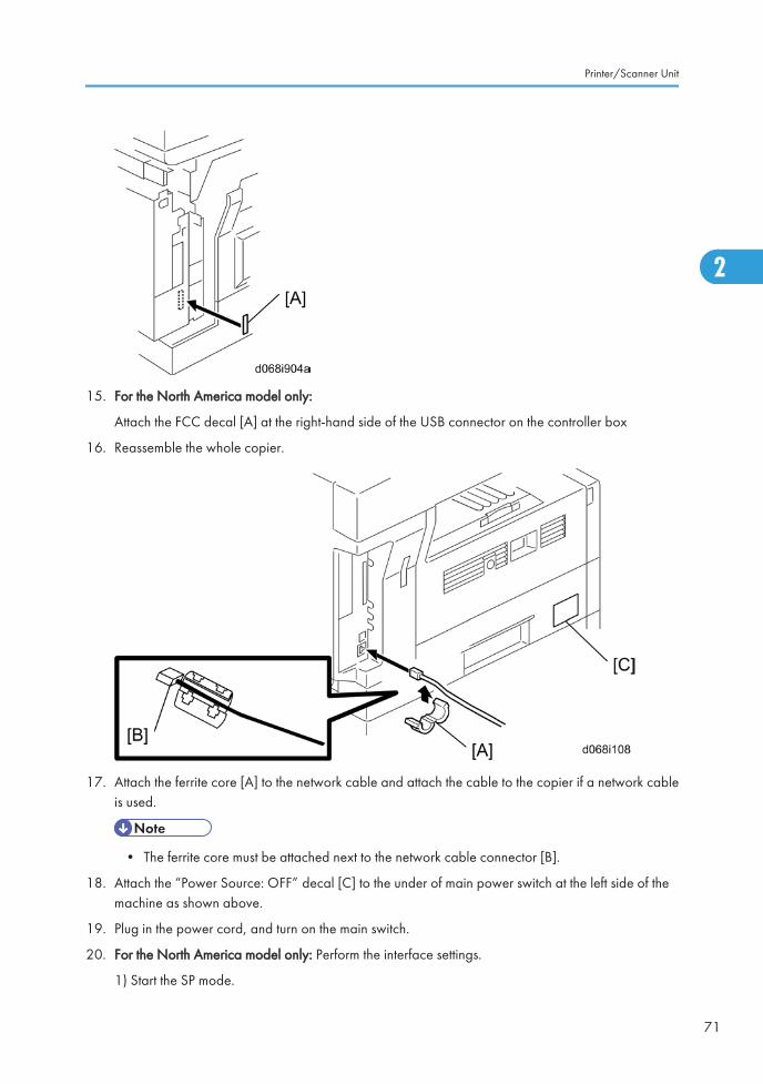
15. For the North America model only:
Attach the FCC decal [A] at the right-hand side of the USB connector on the controller box
16. Reassemble the whole copier.
17. Attach the ferrite core [A] to the network cable and attach the cable to the copier if a network cableis used.
• The ferrite core must be attached next to the network cable connector [B].
18. Attach the “Power Source: OFF” decal [C] to the under of main power switch at the left side of themachine as shown above.
19. Plug in the power cord, and turn on the main switch.
20. For the North America model only: Perform the interface settings.
1) Start the SP mode.
Printer/Scanner Unit
71
2

2) Select SP5-985-001 (NIC setting) and change the setting value to "1" (ON).
3) Select SP5-985-002 (USB setting) and change the setting value to "1" (ON).
4) Turn the main switch off and on.
21. Perform the Printer/Scanner settings.
1) Start the SP mode.
2) Select SP5-801-001 and execute the initialization.
3) Exit the SP mode, and then start the UP mode.
4) Select the "@Remote Service" ("User Tool" > "System Settings > Administrator Tools" > "ExtendedSecurity" > @Remote Service") and select "Prohibit".
5) Exit the UP mode, and then start the SP mode.
6) Select SP5-870-003 and execute initialization for @Remote.
7) Select SP5-907-001 and specify the "Plug & Play".
8) Select SP5-870-001 and execute writing certification for `Remote.
9) Select SP5-302-002 and specify the time zone.
10) Select SP5-307-001, 003, and 004 and specify the daylight-saving-time settings.
11) Exit the SP mode and turn the main switch off and on.
12) Start the UP mode.
13) Specify the date and time with "Set Date" or "Set Time" (User Tool" > "System Settings" > "SetDate" or "Set Time").
22. Turn the main switch off and on.
23. Check the operations.
2. Installation
72
2

Controller Options
Overview
This machine has I/F card slots and SD card slots for optional I/F connections and applications.
I/F Card Slot
• Slot [A] is used for one of the optional I/F connections: (IEEE1284, IEEE802.11a/g (Wireless LAN)or Gigabit Ethernet).
SD Card Slot
• Slot [1] is used for options provided on SD cards. The application SD card (HDD Encryption unit,Overwrite Security Unit or PostScript3) should be installed in Slot 1. If more than one application isto be used, move the applications to the same SD card with SP5873.
• Slot [2] is used for options provided on SD cards and servicing. The VM card must be installed in Slot2.
PostScript3 Installation
• Unplug the machine power cord before starting the following procedure.
Controller Options
73
2

Accessories
Check the accessories and their quantities against the table below.Accessories
No. Description Q’ty
1 PostScript 3 Emulation SD Card (D468) 1
2 Decal 1
Installation Procedure
1. Install the PostScript3 SD card [A] into slot 1.
2. Turn on the main power switch.
3. Print out the configuration page (User Tools/ Counter > Printer Features > List/ Test Print), and thencheck that this device is detected.
4. Attach the "Adobe PostScript3" decal to the front cover of the machine.
Wireless LAN (IEEE 802.11a/g) Installation
• Unplug the machine power cord before starting the following procedure.
Accessories
Check the accessories and their quantities against the table below.Accessories
No. Description Q’ty
1 Wireless Adapter 1
2. Installation
74
2

No. Description Q’ty
2 Wireless LAN Card 1
3 LAN Card Cover 4
4 Caution Sheet 1
5 Label 1
Installation Procedure
1. Remove the interface cover [A] ( x 2).
2. Install the Wireless adaptor into I/F slot [B] ( x 2).
3. Install the Wireless LAN card in the wireless adaptor.
4. Attach the antenna cap to the wireless LAN card.
5. Turn on the main power switch.
6. Print out the configuration page (User Tools/Counter > Printer Features > List/Test Print), and thencheck that this device is detected.
If reception is poor, you may need to move the machine:
• Make sure that the machine is not located near an appliance or any type of equipment that couldgenerate a strong magnetic field.
• Position the machine as close as possible to the access point.
Controller Options
75
2

SP Mode Settings for IEEE 802.11a/g Wireless LAN
The following SP commands can be set for IEEE 802.11a/g
SP No. Name Function
5840 004 SSID Used to confirm the current SSID setting.
5840 006 Channel MAX Sets the maximum range of the channel settings for the country.
5840 007 Channel MINSets the minimum range of the channel settings allowed for yourcountry.
5840 011 WEP Key Select Used to select the WEP key (Default: 00).
5840 018 SSID Check Used to check the SSID.
5840 020 WEP ModeUsed to display the maximum length of the string that can beused for the WEP Key entry.
IEEE 1284 Installation
• Unplug the machine power cord before starting the following procedure.
Accessories
Check the accessories and their quantities against the table below.Accessories
No. Description Q’ty
1 IEEE1284 Interface Ass’y 1
2 UL Sheet 1
3 Caution Sheet 1
2. Installation
76
2

Installation Procedure
1. Remove the interface cover [A] ( x 2).
2. Install the IEEE 1284 board into I/F slot [B] ( x 2).
3. Turn on the main power switch.
4. Print out the configuration page (User Tools/Counter > Printer Features > List/Test Print), and thencheck that this device is detected.
VM Card Type L (D467)
Accessories
Check the accessories and their quantities against the table below.Accessories
No. Description Q’ty
1 VM SD Card 1
2 Decal 1
Controller Options
77
2

Installation
1. Switch the machine off.
2. Insert the SD card [A] into SD Slot 2 (lower).
• This SD card must be inserted into Slot 2, the lower slot.
Gigabit Ethernet
• Unplug the main machine power cord before you do the following procedure.
1. Remove the I/F-slot cover [A] ( x 2).
2. Install the Gigabit Ethernet board (Knob-screw x 2) into the I/F-slot [B].
2. Installation
78
2

3. Attach one ferrite core [A] to the Ethernet interface cable, and then attach the other ferrite core [B]about 10cm from the end of the Ethernet interface cable.
4. Connect the Ethernet interface cable to the Gigabit Ethernet port.
Make sure that the machine can recognize this option (see ‘Check All Connections’ at the end of thissection).
HDD Option (D467, only for D067/D068)
Component Check
No. Description Q’ty
1 HDD Unit 1
2 Screw 3
3Keytop: Copy (Not used) 2
Keytop: Document Server (Not used) 2
- Knob Screw (Not used) 3
Controller Options
79
2

Installation Procedure
1. Controller box cover [A] ( x 13)
2. Installation
80
2

1. Remove the screw [A] on the controller board.
2. Install the HDD unit [B] in the controller board ( x 3).
• The screw [A] is used in this step.
3. Reinstall the controller board in the machine.
After Installing the HDD
1. Do SP5832-001 to format the hard disk.
2. Do SP5853-001 to copy the preset stamp data from the firmware to the hard disk.
3. Do SP5846-040 to copy the address book to the hard disk from the controller board.
4. Do SP5846-041 to let the user get access to the address book.
5. Turn the main power switch off/on.
DataOverwriteSecurity Unit Type I (D362)
Before You Begin the Procedure
1. Confirm that the DataOverwriteSecurity unit SD card is the correct type for the machine. The correcttype for this machine is "Type I".
2. Make sure that the following settings are not at their factory default values:
• Supervisor login password
Controller Options
81
2

• Administrator login name
• Administrator login password
If any of these settings is at a factory default value, tell the customer these settings must be changedbefore you do the installation procedure.
3. Make sure that “Admin. Authentication” is ON.
[System Settings] – [Administrator Tools] – [Administrator Authentication Management] - [Admin.Authentication]
If this setting is OFF, tell the customer this setting must be ON before you do the installation procedure.
4. Make sure that “Administrator Tools” is enabled (selected).
[System Settings] – [Administrator Tools] – [Administrator Authentication Management] - [AvailableSettings]
If this setting is disabled (not selected), tell the customer this setting must be enabled (selected) beforeyou do the installation procedure.
Seal Check and Removal
• You must check the box seals to make sure that they were not removed after the items were sealed inthe box at the factory before you do the installation.
1. Check the box seals [A] on each corner of the box.
• Make sure that a tape is attached to each corner.
• The surfaces of the tapes must be blank. If you see “VOID” on the tapes, do not install thecomponents in the box.
2. Installation
82
2

2. If the surfaces of the tapes do not show “VOID”, remove them from the corners of the box.
3. You can see the “VOID” marks [B] when you remove each seal. In this condition, they cannot beattached to the box again.
Installation Procedure
• Unplug the main machine power cord before you do the following procedure.
• You must install the DataOverwriteSecurity unit in SD Card slot 1. However, the Postscript option andothers are also installed in SD Card slot 1. You must do the "SD Card Appli Move" procedure first ifyou want to install the Data Overwrite Security unit.
1. Turn off the main power switch if the machine is turned on.
2. Disconnect the network cable if it is connected.
3. Turn the SD-card label face [A] to the rear of the machine. Then push it slowly into slot 1 until youhear a click.
4. Connect the network cable if it needs to be connected.
5. Turn on the main power switch.
6. Input a machine serial number with SP 5811-001.
7. Go into the SP mode and push “EXECUTE” with SP5-878-001.
8. Exit the SP mode and turn off the operation switch. Then turn off the main power switch.
9. Turn on the machine power.
10. Go into the User Tools mode, and select System Settings> Administrator Tools> Auto Erase MemorySetting> On.
11. Exit the User Tools mode.
Controller Options
83
2

HDD Encryption Unit (D377)
Before You Begin the Procedure
1. Make sure that the following settings are not at the factory default settings:
• Supervisor login password
• Administrator login name
• Administrator login password
• These settings must be set up by the customer before the HDD Encryption unit can be installed.
2. Confirm that "Admin. Authentication" is on:
[User Tools] > "System Settings"> "Administrator Tools"> "Administrator AuthenticationManagement"> "Admin. Authentication"> "On"
If this setting is "Off", tell the customer that this setting must be "On" before you can do the installationprocedure.
3. Confirm that "Administrator Tools" is selected and enabled:
[User Tools]> "System Settings"> "Administrator Tools"> "Administrator Authentication Management">"Available Settings"
• "Available Settings" is not displayed until Step 2 is done.
If this setting is not selected, tell the customer that this setting must be selected before you can do theinstallation procedure.
2. Installation
84
2

Seal Check and Removal
• You must check the box seals to make sure that they were not removed after the items were sealed inthe box at the factory before you do the installation.
1. Check the box seals [A] on each corner of the box.
• Make sure that a tape is attached to each corner.
• The surfaces of the tapes must be blank. If you see “VOID” on the tapes, do not install thecomponents in the box.
2. If the surfaces of the tapes do not show “VOID”, remove them from the corners of the box.
3. You can see the “VOID” marks [B] when you remove each seal. In this condition, they cannot beattached to the box again.
Installation Procedure
Controller Options
85
2

1. Turn the SD-card label to face [A] the rear of the machine. Then push it slowly into slot 1 until youhear a click.
2. Turn on the main power switch, and then enter the SP mode.
3. Select SP5878-002, and then press "Execute" on the LCD.
4. Exit the SP mode after "Completed" is displayed on the LCD.
5. Turn off the main power switch.
6. Remove the SD card from slot 1.
Recovery from a Device Problem
Restoring the Encryption key
When replacing the controller board for a model in which the HDD encryption unit has been installed,updating the encryption key is required.
1. Prepare an SD card which is initialized.
2. Make the "restore_key" folder in the SD card.
3. Make an "nvram_key.txt" file in the "restore_key" folder in the SD card.
4. Ask an administrator to input the encryption key (this has been printed out earlier by the user) into the"nvram_key.txt" file.
5. Remove only the HDD unit ( HDD).
2. Installation
86
2
6. Turn on the main power switch.
7. Confirm that the prompt on the LCD tells you to install the SD card (storing the encryption key) in themachine.
8. Turn off the main power switch.
9. Insert the SD card that contains the encryption key into slot 1.
10. Turn on the main power switch, and the machine automatically restores the encryption key in the flashmemory on the controller board.
11. Turn off the main power switch after the machine has returned to normal status.
12. Remove the SD card from slot 1.
13. Reinstall the HDD unit.
Clearing the NVRAM
When replacing the controller board for a model in which the HDD encryption unit has been installed anda customer has lost the encryption key, clearing the NVRAM is required to recover the HDD encryptionunit.
1. Prepare an SD card which is initialized.
2. Make the "restore_key" folder in the SD card.
3. Make an "nvram_key.txt" file in the "restore_key" folder in the SD card.
4. Input "nvclear" into the "nvram_key.txt" file.
5. Turn on the main power switch.
6. Confirm that the prompt on the LCD tells you to install the SD card (storing the encryption key) in themachine.
7. Turn off the main power switch.
8. Insert the SD card that contains "nvclear" into slot 1.
9. Turn on the main power switch, and the machine automatically restores the encryption key in the flashmemory on the controller board.
10. Turn off the main power switch after the machine has returned to normal status.
11. Remove the SD card from slot 1.
12. Turn on the main power switch.
13. Initialize the NVRAM (SP5801-001) and HDD unit (SP5832-001) with SP mode.
14. The user must enable the HDD encryption unit with a user tool.
Controller Options
87
2

2. Installation
88
2

3. Preventive Maintenance
Maintenance TablesSee "Appendices" for the following information:
• PM tables
89
3

How to Clear the PM CounterReset the PM counter after your maintenance work.
1. Activate the SP mode.
2. Select SP7-804-001.
3. Press the EXECUTE key [A]. The message "Completed" is displayed when the program ends normally.An error message is displayed if the program ends abnormally.
4. Press the Escape key [B] to end the program.
3. Preventive Maintenance
90
3

4. Replacement and Adjustment
Precautions
General
• Turn off the main power switch and unplug the machine before starting replacement.
Before turning off the main power switch, check that no mechanical component is operating. Mechanicalcomponents may stop out of their home positions if you turn off the main power switch while they areoperating. The component may be damaged if you try to remove it when it is not in the home position.
Lithium Batteries
• Incorrect replacement of lithium battery(s) on the controller or on the fax unit poses risk of explosion.Replace only with the same type or with an equivalent type recommended by the manufacturer.Discard used batteries in accordance with the manufacturer’s instructions.
Halogen-free Cable
• Use extreme caution while handling cables.
To comply with local regulations, halogen-free cables are used in this machine. Halogen-free cables areenvironment-friendly, but no stronger than conventional cables. These cables may be damaged in any ofthe following cases:
• The cable is caught between hard objects such as brackets, screws, PCBs, and exterior covers.
• The cable is rubbed on a hard object such as brackets, screws, PCBs, and exterior covers.
• The cable is scratched with a hard object such as brackets, screws, PCBs, exterior covers,screwdrivers, and fingernails.
91
4

Special Tools and LubricantsPart Number Description Q’ty
A1849501 Optics Adjustment Tools (2 pcs/set) 1 set
A2929500 Test Chart – S5S (10 pcs/set) 1 set
VSSM9000 Digital Multimeter – Fluke 87 1
N8036701 Flash Memory Card (4MB) 1
N8031000 Case for Flash Memory Card 1
A2579300 Grease Barrierta – S552R 1
52039502 Silicon Grease 501 1
4. Replacement and Adjustment
92
4

Exterior Covers and Operation Panel
Rear Cover
1. Open the right door [A].
2. Interface cover [B] ( x 1)
3. Open the right door [A].
4. Rear cover [C] ( x 5)
Copy Tray
• Make sure that the cables under the copy tray are in place before reassembling the copier. If thesecables are caught between the copy tray and the inner cover, they may be severely damaged.
Exterior Covers and Operation Panel
93
4

1. Open the front door [A].
2. Copy tray [B] ( x1)
Reassembling:
There are several cables under the front end of the copy tray. To set these cables in place, gently pull thesecables to the left-hand side (toward the PSU) and hold them there as you attach the copy tray.
Scale Plate (D067 only)
1. Scale plate [A] ( x 2)
4. Replacement and Adjustment
94
4

Operation Panel and Upper Covers
1. Remove the ARDF.
• For D072: Remove the ARDF, if it has been installed.
2. Rear cover ( "Rear Cover")
3. Slide the upper left cover [A] to the rear.
4. Rear scale [B] ( x 3)
5. Slide the upper right cover [C] to the rear.
6. Front left cover [D] ( x 2)
7. Operation panel [E] ( x 4, x 1)
8. Front right cover [F]
Exterior Covers and Operation Panel
95
4

Right Door
1. Open the right door [A].
2. Release the strap [B].
3. Right door ( x 1)
Bypass Tray
4. Replacement and Adjustment
96
4

1. Press the stopper rails [A] inward.
Platen Cover Sensor
1. Rear cover ( "Rear Cover")
2. Rear scale ( "Operation Panel and Upper Covers")
3. Platen cover sensor [A] ( x 1, hook)
Exterior Covers and Operation Panel
97
4

Scanner UnitTo clean the mirrors and lenses, use a blower brush or wet cotton.
Exposure Glass
To clean the exposure glass, use alcohol or glass cleaner.
Non-ARDF machines
1. Rear cover ( "Rear Cover")
2. Scale plate ( "Operation Panel and Upper Covers")
3. Exposure glass [A]
ARDF-equipped machines
1. Rear cover ( "Rear Cover")
2. Rear scale, upper right cover ( "Operation Panel and Upper Covers")
3. Exposure glass [A]
Reassembling
Make sure that the marking on the glass is at the rear left corner, and that the left edge of the glass is alignedflush against the support ridge [B] on the frame.
Adjustment
When replacing the white plate, perform the "Scan Auto Adjustment" ( SP4-428-001).
4. Replacement and Adjustment
98
4

Lens Block
• Do not disassemble the lens block. The lens block is precision adjusted before shipment.
• Do not touch the screws on the CCD. The CCD is precision adjusted before shipment.
1. Exposure glass ( "Exposure Glass")
2. Front left cover, operation panel ( "Operation Panel and Upper Covers")
3. Release the cable from the four clamps [A].
4. Lens block [B] ( x 4, 1 flat cable)
• Do not loosen the paint-locked screws holding the lens unit in place.
• After installing a new lens block, carry out copy adjustments ( "Adjusting Copy Image Area").
Exposure Lamp, Lamp Stabilizer Board
Do not fold the exposure cable on the exposure lamp.
Scanner Unit
99
4

1. Exposure glass ( "Exposure Glass")
2. Front left cover, operation panel ( "Operation Panel and Upper Covers")
3. Slide the first scanner to a position where the lamp and scanner are clear of the metal lids.
4. Disconnect the lamp connector [A].
5. Remove either or both of the following:
• Exposure lamp [B] ( x 1)
• Lamp stabilizer board [C] ( x 2, 1 flat cable)
Scanner Motor
1. Rear cover ( "Rear Cover")
2. Rear scale, upper right cover ( "Operation Panel and Upper Covers")
4. Replacement and Adjustment
100
4

3. Remove the right platen stay holder [A] ( x 3).
4. Scanner motor [B] ( x 3, 1 spring, 3 screw holders, x 1)
Reinstalling
When reinstalling, fasten the screws loosely, set the spring in place, and tighten up the screws.
Scanner Unit
101
4

Scanner HP Sensor
1. Rear cover ( "Rear Cover")
2. Front left cover ( "Operation Panel and Upper Covers")
3. Scale plate ( "Scale Plate")
4. Scanner HP sensor [A] ( x 1, hook)
• Move the first scanner from the home position if you have difficulty removing the sensor.
Scanner Alignment Adjustment
1. Rear cover ( "Rear Cover")
2. Rear scale, upper right cover, front left cover, operation panel ( "Operation Panel and UpperCovers")
3. Exposure glass ( ”Exposure Glass")
4. Loosen the 2 screws holding the 1st and 2nd scanner belts in place.
4. Replacement and Adjustment
102
4

5. Slide the 1st and 2nd scanners so that all four of the following are roughly aligned on both the frontand back sides:
• The hole in the copier's lid
• The hole in the 1st scanner
• The right corner hole in the 2nd scanner
• The hole at the base of the scanner
6. Insert the two optics adjustment tools [A], and adjust the scanners as necessary so that the tools gothrough all four holes.
7. Tighten the two screws that you loosened at step 2 above, so that the belts are firmly clamped intoplace.
8. Remove the adjustment tools.
Scanner Unit
103
4
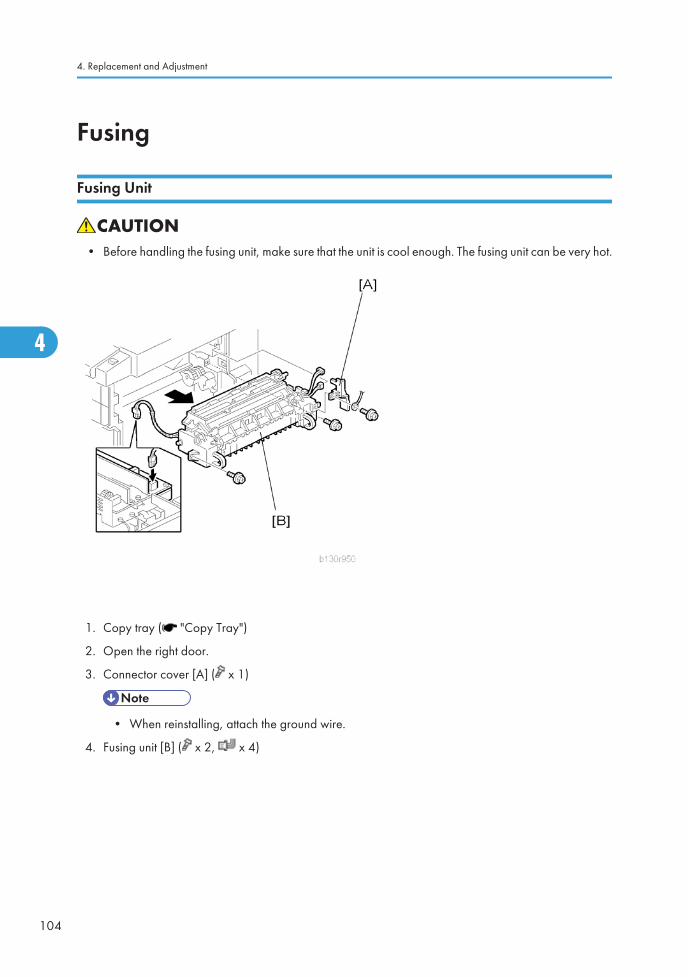
Fusing
Fusing Unit
• Before handling the fusing unit, make sure that the unit is cool enough. The fusing unit can be very hot.
1. Copy tray ( "Copy Tray")
2. Open the right door.
3. Connector cover [A] ( x 1)
• When reinstalling, attach the ground wire.
4. Fusing unit [B] ( x 2, x 4)
4. Replacement and Adjustment
104
4

Exit Sensor
1. Fusing unit ( "Fusing Unit")
2. Exit sensor [A] ( x 1)
Hot Roller Stripper Pawls
• Take care not to damage the hot roller stripper pawls and the tension springs.
Fusing
105
4

1. Fusing unit ( "Fusing Unit")
2. Separate the fusing unit into two sections: the hot roller section [A] and the pressure roller section [B]( x 2).After removing the screws, lower the pressure roller section about halfway and then slide it towardthe front side to detach it.
3. Support rollers [C]
4. Hot roller stripper pawls [D]
• Remove the spacer [E] ( x 1) if you are removing the hot roller assembly ( "Hot Roller &Fusing Lamp").
Hot Roller and Fusing Lamp
• Do not touch the fusing lamp and rollers with your bare hands.
4. Replacement and Adjustment
106
4

1. Hot roller stripper pawls and spacers ( "Hot Roller Stripper Pawls")
2. Hot roller assembly [A] ( x 2)
3. Fusing lamp [B]
• When reassembling, check that the direction of the fusing lamp is correct.
4. Hot roller [C] (2 C-rings, 1 spacer, 1 gear, 2 bushings, 1 cover [D])
Reassembling
Be sure that:
• The fusing lamp is positioned correctly.
• The fusing lamp does not touch the internal part of the hot roller.
Fusing
107
4

Thermoswitches and Thermistor
1. Hot roller assembly ( "Hot Roller & Fusing Lamp")
2. Thermoswitches ( x 2 for each)
3. Thermistor ( x 1)
Reassembling
Make sure of the following:
• That the thermistor is in contact with the hot roller.
• That the hot roller turns smoothly.
• Do not recycle a thermoswitch that is already opened. Safety is not guaranteed if you do this.
4. Replacement and Adjustment
108
4

Pressure Roller
1. Separate the fusing unit into two sections ( "Hot Roller Stripper Pawls").
2. Fusing entrance guide [A]
3. Two springs [B][C]
4. Two pressure arms [D][E]
5. Bushing [F]
6. Pressure roller [G]
Fusing
109
4

Checking the NIP band
You can check the nip band to see if the fusing unit is in a good condition–especially, if the hot roller andpressure roller are correctly installed.
1. Activate the SP mode.
2. Select SP1-109-001.
3. Specify "1."
4. Press the OK key.
5. Press the key. The copy mode is activated.
6. Place an OHP sheet on the by-pass tray.
7. Press the key. The copier feeds the OHP sheet, and stops it between the hot roller and the pressureroller for about 20 seconds.
8. Wait until the OHP sheet is output.
9. Press the key.
10. Make sure SP1-109-001 is selected.
11. Specify "0".
12. Press the OK key.
13. Quit the SP mode.
You see an opaque stripe on the OHP sheet. This is the trace of the nip band. The normal nip band issymmetrical on the OHP sheet. Both ends are slightly thicker than the center.
• There are no specifications or standards for the nip band of this copier.
4. Replacement and Adjustment
110
4

PCU and Quenching LampWhen handling the photo conductor unit (PCU), use caution:
• Do not touch the OPC drum with your bare hands. When the OPC drum is unclean, clean it with drycloth, or clean it with wet cotton and wipe it with dry cloth.
• Do not use alcohol or any other chemicals to clean the OPC drum. These substances damage theOPC-drum surface.
• Keep PCUs in a cool, dry place.
• Do not expose the OPC to any corrosive gas such as ammonia.
• Do not shake a used PCU. Remaining toner and developer may spill out.
• Dispose of used PCUs in accordance with local regulations.
PCU
1. Open the right door.
• The PCU may become stuck if you try to remove it while the front door is closed.
2. Open the front door.
3. Remove the toner bottle holder.
• Clean all spilled toner off the toner bottle area and the inside of the front door.
4. Pull out the PCU [A] ( x 1).
5. When having installed a new PCU, remove the Styrofoam and tags ( "Installation Procedure" inthe chapter "Installation").
Initialization
PCU and Quenching Lamp
111
4

After you turn on the main power switch, the copier automatically initializes the new PCU. When the copieris executing initialization, it is important that you:
• Do not turn off the main power switch.
• Do not open or remove exterior covers.
Quenching Lamp
1. PCU ( "PCU")
2. Quenching lamp [A] ( x 1)
4. Replacement and Adjustment
112
4

Exhaust Fan and Main Motor
Exhaust Fan
1. Rear cover ( "Rear Cover")
2. Exhaust fan [A] ( x 2, x 1)
Reassembling
Make sure that the arrow [B] on the frame points to the rear side. The arrow indicates the direction ofairflow.
Exhaust Fan and Main Motor
113
4

Main Motor
1. Rear cover ( "Rear Cover")
2. High-voltage power supply board ( "High-Voltage Power Supply Board")
3. Ground plate [A] ( x 1)
4. Main motor with the gear cover [B] ( x 1, x 7, x 2, 2 bushings)
5. All gears [C]
6. Main motor [D] ( x 4)
Reassembling
Attach the main motor before attaching the gears.
4. Replacement and Adjustment
114
4

Paper Feed
Paper Feed Roller and Friction Pad
When handling the paper tray or the paper feed roller, use caution:
• Do not touch the surface of paper feed rollers.
• To avoid paper jams, correctly set the side and end fences in the paper tray.
1. Paper tray
2. Shaft [A] ( x 1)
3. Remove either or both of the following:
• Paper feed roller [B]
• Friction pad [C]
Paper Feed
115
4

Paper End Sensor
1. Paper tray
2. Open the right door.
3. PCU ( ”PCU")
4. Paper end sensor [A] ( x 1)
Registration Sensor
1. Paper tray
2. Open the right door.
3. Open the paper guide [A].
• Remove the paper guide (Clip x 1) if you have difficulty removing the registration sensor.
4. Replacement and Adjustment
116
4

4. Registration sensor feeler [B]
5. Registration sensor [C] ( x 1)
• Disconnect the connector (CN127 [D]) if you have difficulty removing the registration sensor.
Bypass Paper End Sensor
1. Right door ( "Right Door")
2. Sensor compartment [A]
3. Bypass paper end sensor [B] ( x 1)
Paper Feed
117
4

Bypass Feed Roller
1. Right door ( "Right Door")
2. Turn the feed roller housing upside down [A] ( x 2).
3. Feed roller shaft [B] (2 snap pawls [C], 1 spacer [D])
4. Bypass feed roller [E]
4. Replacement and Adjustment
118
4

Bypass Feed Clutch and Friction Pad
1. Rear cover ( "Rear Cover")
2. Right door ( "Right Door")
3. Disconnect the bypass feed clutch connector [A] (CN93).
4. Bypass feed roller housing [B] ( x 2)
5. Bypass feed clutch [C] ( x 1)
6. Bypass friction pad [D]
Paper Feed
119
4

Paper Feed and Registration Clutches
1. Paper tray
2. High-voltage power supply board ( "High-Voltage Power Supply Board")
3. Ground plate [A] ( x 1)
4. Gear cover [B] ( x 1, x 7, x 2, 2 bushings)
• Do not remove the main motor from the gear cover.
4. Replacement and Adjustment
120
4

5. Ground plate [C] ( x 1)
6. Slowly push the clutch holder [D] and remove the registration clutch [E] ( x 1, x 1).
7. Paper feed clutch [F]
Paper Feed
121
4

Image Transfer
Transfer Roller
• Do not touch the transfer roller with your bare hands.
• Do not scratch the transfer roller. The transfer roller is easily damaged.
1. Right door ( "Right Door")
2. Raise the levers [A],[B] at the ends of the image transfer roller.
3. Release the image transfer roller [C].
Reassembling
Make sure that the springs [D] are in the original positions.
4. Replacement and Adjustment
122
4

ID Sensor and Duplex Roller
1. Right door ( "Right Door")
2. Lower guide [A]
3. Idle roller holders [B][C]
4. Idle roller [D]
5. Roller guide [E]
6. Transfer unit [F]
7. One-way gear [G] ( x 1)
8. Duplex roller [H] ( x 1, 3 bushings)
Image Transfer
123
4

9. ID sensor [I] ( x 1)
Discharge plate
1. Right door ( "Right Door")
2. Discharge plate [A]
4. Replacement and Adjustment
124
4

BICU and Controller Board
• Turn off the main power switch and unplug the machine before starting replacement.
• Before turning off the main power switch, check that no mechanical component is operating.Mechanical components may stop out of their home positions if you turn off the main power switchwhile they are operating. The component may be damaged if you try to remove it when it is not in thehome position.
For basic models (D067/D072):
The table lists the components and necessary maintenance work
ModelBICU
NVRAMController Box
ControllerNVRAM
Maintenance Work
Basic Installed None NoneSave the data from the NVRAM to amemory card before replacing theNVRAM.
BICU
Preparation
• Before replacing the NVRAM, be sure to save the NVRAM data.
• Saving from the BICU NVRAM to an SD card ( "NVRAM Data Upload/Download(SP5-824/825)" in the "System Service Mode" of the appendices of the this manual.)
BICU and Controller Board
125
4

Procedure
1. Rear cover ( "Rear Cover")
2. Scanner upper left cover ( "Operation Panel and Upper Covers”)
3. Bracket at the left-rear frame (basic models [D067/D072]: x 2) or controller box [A] (F/SPF models[D068/D069]: x 6, x 1)
4. Ground plate [B] ( x 2)
4. Replacement and Adjustment
126
4

5. BICU [C] (all , 2 flat cables, x 6)
• When replacing the BICU, remove the NVRAM [D] from the board. Install the NVRAM to thenew board.
6. After replacing the NVRAM, copy the saved data to the NVRAM.
• From an SD card to the NVRAM ( "NVRAM Data Upload/Download (SP5-824/825)" inthe "System Service Mode" of the appendices of the this manual.)
Controller Board (F/SPF models: D068/D069)
Preparation:
• Before replacing the controller board, be sure to print out SMC or save the NVRAM data.
• Saving from the Controller NVRAM to an SD card ( "NVRAM Data Upload/Download(SP5-824/825)" in the "System Service Mode" of the appendices of the this manual.)
Procedure
1. Rear cover ( "Rear Cover")
2. Scanner upper left cover (* "Operation Panel and Upper Covers”)
3. FCU ( "FCU")
BICU and Controller Board
127
4

4. Remove the printer/scanner SD card.
5. Remove I/F cover [A] (or I/F options if they have been installed) ( x 2).
6. Remove the bracket [B] ( x 1).
7. Remove the USB cap [C].
4. Replacement and Adjustment
128
4

8. Remove the relay connector [A].
9. Remove the ground plate [B] ( x 1).
10. Remove the controller board with the rails [C] ( x 6).
BICU and Controller Board
129
4

11. Release the hooks, and then pull out the rails [A].
12. Remove the DIMM [B] if it has been installed.
• When replacing the controller board, remove the NVRAMs from the board. Install the NVRAMsto the new board.
4. Replacement and Adjustment
130
4

When replacing the NVRAM on the controller board
1. When you replace the NVRAM [A], make sure that the NVRAM is correctly installed.
2. The mark [B] on the NVRAM should be directed to the down side (seem from the back side of themachine).
3. Reassemble the machine.
4. Copy the old NVRAM data to the new NVRAM with SP5-825 or input the SMC data in the machine.(For details, refer to the "NVRAM Data Upload/Download [SP5-824/825]" in the "System ServiceMode" of the appendices of the this manual)
When Installing the Printer/Scanner Unit (D468)
Refer to procedure “Controller Board (F/SPF models: D068/D069)” in this section, and carry out thesteps (without step 3).
BICU and Controller Board
131
4

Other Replacements
Duplex Motor
1. Rear cover ( "Rear Cover")
2. Duplex motor [A] ( x 1, x 2)
4. Replacement and Adjustment
132
4

High-Voltage Power Supply Board
1. Rear cover ( "Rear Cover")
2. High-voltage power supply board [A] (all , x 4)
• Remove the insulating sheet [B] if you are going to remove the contact-release solenoid ("Contact-Release Solenoid") or the gear cover ( "Paper Feed and Registration Clutches").
Other Replacements
133
4

PSU
1. Open the front door.
2. Copy tray ( "Copy Tray")
3. PSU assembly [A] ( x 4, x 8)
4. PSU [B] ( x 4, x 6)
4. Replacement and Adjustment
134
4

Contact-Release Solenoid
1. Rear cover ( "Rear Cover")
2. High-voltage power supply board ( "High-Voltage Power Supply Board")
3. Contact-release solenoid [A] (1 spring, x 1)
Toner Supply Clutch
1. Toner bottle holder
Other Replacements
135
4

2. Copy tray ( "Copy Tray")
3. Rear cover ( "Rear Cover")
4. Disconnect the connector on C19 on the BICU.
5. Push the clutch coupler [A] to the rear side, and remove the clip ring [B] from the back of the copier.
6. Coupler and spring [C]
7. Lift the toner supply clutch [D] and remove it.
• When removing, note how the wire goes through a clamp, and also note where it passes throughthe rear of the machine.
FCU (For D068/D069)
Lithium Batteries
• Incorrect replacement of lithium battery(s) on the controller or on the fax unit poses risk of explosion.Replace only with the same type or with an equivalent type recommended by the manufacturer.Discard used batteries in accordance with the manufacturer’s instructions.
Procedure
1. Open the right door [A].
2. Rear cover [B] ( x 5).
3. Scanner upper left cover [C]
4. Replacement and Adjustment
136
4

4. Controller box cover [A] ( x 13)
5. FCU [A] ( x 4, x 1)
6. When you replace the FCU board, remove the MBU board from the old FCU board and install it onthe new FCU board.
7. Set the correct date and time with the User Tools: User Tools> System Settings> Timer Setting> SetDate/Time
Other Replacements
137
4

• Do not turn off the battery switch (SW1).
• Do SP6-101 in the "Fax SP" to print the system parameters, and check the settings.
4. Replacement and Adjustment
138
4

Laser Unit
• Turn off the main power switch and unplug the copier before starting replacement. The laser beamcan damage your eyes severely.
• Do not touch the screws on the LD board on the LD unit. Do not try to adjust any part of the LD unit.The LD unit is precision adjusted before shipment.
• Do not touch the polygon mirror, shield glass, or lenses with your bare hands.
Location of the Caution Decal
Laser Unit
1. PSU assembly ( "PSU")
2. Toner bottle holder
3. Laser unit [A] ( x 3, x 2)
Reassembling
Laser Unit
139
4

Make sure that the cable [B] passes under the unit.
LD Unit and Polygon Mirror Motor
1. Laser unit ( "Laser Unit")
2. Laser unit cover [A] ( x 2, 1 grounding plate)
3. LD unit [B] ( x 2)
4. Polygon mirror motor [C] ( x 4)
Reassembling
Check that the polygon mirror and toroidal lens are clean. Dust or other foreign substances may interferewith the operation of the LD unit.
4. Replacement and Adjustment
140
4

ARDF
ARDF
1. Rear cover ( "Rear Cover")
2. Remove the DF interface cables [A] ( x 2, hook x 2).
3. Remove the ground cable [B] ( x 1).
4. Remove the stud screw [C].
5. Remove the ARDF [D].
ARDF
141
4

DF Rear Cover
1. Open the ARDF [A].
2. Release the three hooks
3. Open the DF left cover [B].
4. Open the original tray [C].
5. DF rear cover [D] ( x 1, hook x 4)
Original Feed Unit
1. Open the DF left cover.
4. Replacement and Adjustment
142
4

2. Original feed unit [A] (c x 1)
Separation Roller
1. Open the DF left cover.
2. Original feed unit ( "Original Feed Unit")
3. Separation roller cover [A] (hook x 2)
4. Separation roller stopper [B] (hook)
5. Separation roller [C]
DF Drive Board
1. DF rear cover ( "DF Rear Cover")
ARDF
143
4

2. DF drive board [A] ( x 2, x 4, ground cable x 1)
Original Set and DF Inverter Sensor
1. Open the DF left cover.
2. Original feed unit ( "Original Feed Unit")
3. DF feed clutch ( "DF Feed Clutch")
4. Original feed-in guide plate [A] ( x 2).
5. Original set sensor [B] ( x 1, hook)
6. DF inverter sensor [C] ( x 1, hook)
4. Replacement and Adjustment
144
4

DF Registration and DF Exit Sensor
1. Open the DF left cover.
2. Original feed unit ( "Original Feed Unit")
3. DF feed clutch ( "DF Feed Clutch")
4. Original feed-in guide plate ( "Original Set and Inverter Sensor")
5. DF feed motor ( "DF Feed Motor")
6. DF transport motor ( "DF Transport Motor")
7. DF transport roller [A] ( x 2, gear x 2, bushing x 2)
8. DF separation roller unit [B] ( x 2, gear x 1, bushing x 2)
9. Inverter upper guide plate [C] ( x 4, x 3, x 4)
ARDF
145
4

10. Inverter lower guide plate [D] (hook x 2)
11. DF registration sensor [E] ( x 1, hook)
12. DF exit sensor [F] ( x 1, hook)
DF Registration Sensor Reflector
Clean the SD registration sensor reflector [A] as necessary.
DF Feed Motor
1. DF rear cover ( "DF Rear Cover")
4. Replacement and Adjustment
146
4

2. Inner cover [A] ( x 1)
3. DF feed motor with bracket [B] ( x 2, x 4, x 3, timing belt)
4. DF feed motor [C] ( x 2)
DF Transport Motor
1. DF rear cover ( "DF Rear Cover")
2. DF feed motor ( "DF Feed Motor")
3. DF transport motor with bracket [A] ( x 2, spring x 1, timing belt)
ARDF
147
4

4. DF transport motor [B] ( x 2)
DF Feed Clutch
1. Open the DF left cover.
2. DF front cover [A] ( x 1)
3. Bracket [B] ( x 1, x 1)
4. DF feed clutch [C] ( x 1)
4. Replacement and Adjustment
148
4

Adjusting Copy Image AreaAdjust the copy image area under any of the following conditions:
1. After clearing engine data (SP5-801-002 or SP5-998-001).
2. After replacing any of the following components:
• First scanner or second scanner
• Lens block
• Scanner motor
• Polygon mirror motor
• Paper tray
Printing
Make sure that the paper is correctly loaded in each paper tray before starting the adjustment proceduresin this section.
Adjusting Registration
Use the Trimming Area Pattern (SP5-902-001 > 10) for this adjustment.
1. Print out the test pattern with the paper fed from the regular paper tray.
2. Print out the test pattern with the paper fed from the by-pass tray.
3. Print out the test pattern by selecting duplex printing.
4. Measure the distance between the leading edge of the image area and the leading edge of the paper[A].
• The diagram shows the paper on the copy tray. Note that the paper is output with the face down.
Adjusting Copy Image Area
149
4

SP Specification
SP1-001-001 (All Trays) 0 ± 2 mm
SP1-001-002 (By-pass) 0 ± 2 mm
SP1-001-003 (Duplex) 0 ± 4 mm
5. Adjust the leading edge registration (SP1-001).
6. Measure the distance between the side edge of the image area and the side edge of the paper [B].
SP Specification
SP1-002-001 (1st tray) 0 ± 2 mm
SP1-002-002 (2nd tray) 0 ± 2 mm
SP1-002-005 (By-pass) 0 ± 4 mm
SP1-002-006 (Duplex) 0 ± 4 mm
7. Adjust the side-to-side registration (SP1-002).
8. Specify "0" (zero) in SP5-902-001 after finishing the adjustment procedure.
Adjusting Blank Margin
Use the Trimming Area Pattern (SP5-902-001 > 10) for this adjustment.
1. Print out the test pattern.
2. Measure the distance between the four edges of the image area and the four edges of the paper [A][B][C][D].
• The diagram shows the paper on the copy tray. Note that the paper is output with the face down.
4. Replacement and Adjustment
150
4

3. Adjust the blank margin (SP2-101).
SP Specification
SP2-101-001 (Leading Edge) [A] 2 ± 1.5 mm
SP2-101-002 (Trailing Edge) [B] 2 +2.5/-1.5 mm
SP2-101-003 (Left Side) [C] 2 ± 1.5 mm
SP2-101-004 (Right Side) [D] 2 +2.5/-1.5 mm
• The "Left Side" and "Right Side" comes to your left-hand side and right-hand side respectivelywhen you view the copied image with the leading edge upwards.
4. Specify "0" (zero) in SP5-902-001 after finishing the adjustment procedure.
Adjusting Main-Scan Magnification
Use the Grid Pattern (Single Dot) (SP5-902-001 > 5) for this adjustment.
SP Specification
SP2-998-001 (Main Mag-print) 100 ± 1%
1. Print out the test pattern.
2. Measure the sides of squares. Each side should be 2.7-mm long.)
3. Adjust the main-scan magnification (SP2-998-001: Main Mag-print).
4. Specify "0" (zero) in SP5-902-001 after finishing the adjustment procedure.
Scanning
Preparation:
• Before adjusting scanning, adjust printing ( "Printing" in this section).
• To adjust scanning, use the A4 test chart.
Adjusting Registration
1. Place the test chart on the exposure glass. Make sure that the test chart is aligned with the rear andleft scales on the exposure glass.
Adjusting Copy Image Area
151
4

2. Make a copy.
3. Measure the distance between the leading edge of the image area and the leading edge of the paper[A].
• The diagram shows the paper on the copy tray. Note that the paper is output with the face down.
4. Adjust the leading-edge scan registration. (SP4-010-001).
SP Specification
SP4-010-001 (LE Scan Regist) 0 ± 2 mm
5. Measure the distance between the side edge of the image area and the side edge of the paper [B].
6. Adjust the side-to-side registration (SP4-011-001).
SP Specification
SP4-011-001 (S-to-S Scan Regist) 0 ± 2 mm
4. Replacement and Adjustment
152
4

Adjusting Magnification
1. Place the test chart on the exposure glass. Make sure the test chart is aligned with the rear and leftscales on the exposure glass.
2. Make a copy.
3. Compare the copy with the original.
4. Adjust the main-scan and sub-scan magnifications. The original image [A] is magnified in the main-scan direction [B] or in the sub-scan direction [C] when you specify a larger value.
• The diagrams show the paper on the copy tray. Note that the paper is output with the face down.
SP Specification
SP4-009-001 (Main Scan Mag) ± 1.0%
SP4-008-001 (Sub Scan Mag) ± 1.0%
Scan Auto Adjustment
This procedure adjusts the standard white density level. Adjust the standard white density after any of thefollowing maintenance work:
• Replacing the standard white plate
• Replacing the BICU
Adjusting Copy Image Area
153
4

• Replacing the lens block
• Executing the memory clear (SP5-801-002 [basic model], SP5-998-001 [other models]).
1. Place 10 sheets of new A4 paper on the exposure glass.
2. Close the platen cover.
3. Activate the SP mode.
4. Select Copy SP4-428.
5. Specify "1" and press the OK key. The copier automatically adjusts the standard white density.
DF Image Adjustment
• Perform the adjustment procedure in this section only when the ARDF is installed on the copier.
1. Make a temporary test chart as shown in the above diagram. Use the “A4/8.5 x 11" paper to makeit.
2. Place the temporary test chart on the ARDF.
3. Make a copy.
4. Measure the distance between the side edge of the image area and the side edge of the paper [A].
4. Replacement and Adjustment
154
4

(The diagram shows the paper on the copy tray. Note that the paper is output with the face down.)
5. Adjust the side-to-side registration (S to S/Front Regist: SP6-006-001, S to S/Rear Regist:SP6-006-004). The image area moves to the rear side of the copier when you specify a larger value.
6. Measure the distance between the leading of the image area and the leading edge of the paper [B].
7. Adjust the leading edge registration (Leading Regist: SP6-006-002). The image area moves to theright side of the copier when you specify a larger value.
8. Measure the distance between the trailing edge of the image area and the trailing edge of the paper[C].
9. Adjust the erased area on the trailing edge (Trailing Erase: SP6-006-003).
10. Compare the copy with the original.
11. Adjust the sub-scan magnification (SP6-006-005). The specification is ±1.0%.
Adjusting Copy Image Area
155
4

4. Replacement and Adjustment
156
4

5. Troubleshooting
Service Call ConditionsFor "SC Table" information, see "Appendices".
157
5

Electrical Component DefectsSee "Appendices" for the following information:
• Sensor/Switch
• Blown Fuse Conditions
(Power Supply Unit)
• BICU LED Display
5. Troubleshooting
158
5

Card Save Function
Overview
Card Save:
• The Card Save function is used to save print jobs received by the printer on an SD card with no printoutput. Card Save mode is toggled using printer Bit Switch #1 bit number 4. Card Save will remainenabled until the SD card becomes full, or until all file names have been used.
• Captures are stored on the SD card in the folder /prt/cardsave. File names are assigned sequentiallyfrom PRT00000.prn to PRT99999.prn. An additional file PRT.CTL will be created. This file contains alist of all files created on the card by the card save function.
• Previously stored files on the SD card can be overwritten or left intact. Card Save SD has “Add” and“New” menu items.
• Card Save (Add): Appends files to the SD Card. Does not overwrite existing files. If the cardbecomes full or if all file names are used, an error will be displayed on the operation panel.Subsequent jobs will not be stored.
• Card Save (New): Overwrites files in the card's /prt/cardsave directory.
Limitation:
• Card Save cannot be used with PJL Status Readback commands. PJL Status Readbacks will not work.In addition they will cause the Card Save to fail.
Procedure
1. Turn the main power switch OFF.
2. Insert the SD card into the service slot of the controller board. Then turn the power ON.
• To determine which slot is the service slot, please see the service manual.
3. Enter SP mode.
4. Select “Printer SP”.
5. Select “Service Mode” and press “OK” button.
6. Select “1.001 Bit Switch” and press “OK” button.
Card Save Function
159
5

7. Press “OK” button again.
8. Use the numeric key “4” to turn bit 4 ON. The result should look like: 00010000. By doing this CardSave option will appear in “List/Test Print”.
9. Press the “Return” button several times to exit SP Mode.
10. Press the “ ” button.
11. Use the arrow key and select “Printer Features”.
12. Use the arrow key and select “List/Test Print”.
13. Use the arrow key and select “Cardsave (ADD) or Cardsave (New).
5. Troubleshooting
160
5

14. To enable the newly configured settings, select “switch” button and then press the “Return” button toexit the “List/Test Print” menu.
15. Send a job to the printer.
16. As soon as the printer receives the data, it will be stored on the SD card automatically with no printoutput. Nothing is displayed on the screen indicating that a Card Save operation was successful.
17. Press the “Return” button to exit Card Save mode.
18. Change the Bit Switch Settings back to the default 00000000.
19. Remove the SD card after main power switch is turned off.
Error Messages
Card Save error messages:
• Init error: A card save process (i.e. card detection, change to kernel mode) failed to initialize.
• Card not found: Card cannot be detected in the slot.
• No memory: Insufficient working memory to process the job.
• Write error: Failed to write to the card.
• Other error: An unknown error occurred.
If an error occurs, pressing “OK” will cause the device to discard the job and return to the ready state.
Card Save Function
161
5

Fax Troubleshooting Guide (Only For D068/D069)See "Appendices" for the following information:
• Fax Error Codes
• IFAX Troubleshooting
• IP-Fax Troubleshooting
5. Troubleshooting
162
5

6. System Maintenance Reference
Service Program
• Do not let the user access the SP mode or the SSP mode. Only service representatives are allowed toaccess these modes. The machine operation is NOT guaranteed after any person other than servicerepresentatives accesses the SP mode.
SP Tables
See "Appendices" for the following information:
• Service Program Mode Tables for F/SFP models (D068/D069)
• Service Program Mode Tables for Basic models (D067/D072)
Using SP and SSP Modes
The following two modes are available:
• SP Mode (Service Program Mode): The SP Mode includes the programs that are necessary forstandard maintenance work.
• SSP Mode (Special SP Mode): The SSP Mode includes SP-Mode programs and some specialprograms. You need some extra knowledge to use these special programs. For details, consult yoursupervisor.
163
6

Starting SP Mode
1. Type the keys as follows: Ô Ô Ô
2. Press the key and hold it down until the SP-mode menu is displayed (about 3 seconds).
Selecting Programs
• When a blinking underscore (or several blinking underscores) is displayed, you can type a numberfrom the numeric keypad [D].
• When the sign “ /OK” [A] is displayed upper right corner, you can scroll through the menu bypressing the left-arrow key [B] or the right-arrow key [C]. To select program, press the OK key [F].
Specifying Values
1. After locating a program, press the OK key. A blinking underscore (or several blinking underscores)indicates which value you can change. The value in parentheses is the default value of the menu.
2. Type a necessary value from the numeric keypad. To switch between positive (plus) and negative(minus) values, press the J key.
3. To validate the value, press the OK key. To cancel the value, press the escape key [E].
Activating Copy Mode
You can activate the copy mode while the SP mode is running. When you do so, the copier outputs imagesor patterns that help you adjust the SP setting.
1. Press the key. The copy mode is activated.
2. Specify copy settings and press the key.
3. To return to the SP mode, press the key.
• You cannot end the SP mode while the copy mode is activated.
Quitting Programs/Ending (S) SP Mode
Press the key or the escape key to quit the program. You can end the SP mode by pressing one ofthese keys several times.
Conventions used in the tables:
• Asterisk (*): The settings are saved in the NVRAM. Most of them return to the default values when youexecute SP5-801-002. CTL indicates that the data is contained in NVRAM on the controller board.
6. System Maintenance Reference
164
6

• DFU: The program is for design/factory use only. Do not change the settings.
• Brackets ([ ]): The brackets enclose the setting rage, default value, and minimum step with unit([Minimum to Maximum / Default / Step]).
Service Program
165
6

Using SP Mode (F/SPF: D068/D069)
NVRAM Data Upload/Download
Uploading Content of NVRAM to an SD card
Follow this procedure to upload SP code settings from NVRAM to an SD card.
• This data should always be uploaded to an SD card before the NVRAM is replaced.
1. Before switching the machine off, execute SP 5990-1 (SMC Print). You will need a record of theNVRAM settings if the upload fails.
2. Turn off the main power of the copier.
3. Remove the interface cover ( x 1).
4. Insert the SD card into the service slot 2, then turn on the main power of the copier.
5. Execute SP 5824-1 (NVRAM Data Upload) then press the “Execute” key.
• When uploading is finished, a file is coped to an NVRAM folder on the SD card. The file is savedto the path and filename:
NVRAM\<serial number>.NV
Here is an example with Serial Number “B0700017”:
NVRAM\B0700017.NV
6. In order to prevent an error during the download, be sure to mark the SD card that holds the uploaded(saved) data with the number of the machine from which the data was uploaded (saved).
• NVRAM data from more than one machine can be uploaded (saved) to the same SD card.
7. Turn off the main power, and then remove the SD card from the slot 2.
8. Reassemble the machine.
Downloading an SD Card to NVRAM
Follow this procedure to download (save) SP data from an SD card to the NVRAM in the machine.
• If the SD card with the NVRAM data is damaged, or if the connection between the controller andBICU is defective, the NVRAM data download may fail.
• If the download fails, repeat the download procedure.
• If the second attempt fails, enter the NVRAM data manually using the SMC print you created beforeuploading the NVRAM data. ( above procedure)
6. System Maintenance Reference
166
6

1. Turn off the main power of the copier.
2. Remove the interface cover 2 ( x 1).
3. Insert the SD card with the NVRAM data into the service slot 2.
4. Turn on the main power of the copier.
5. Execute SP 5825-1 (NVRAM Data Download) and press the “Execute” key.
6. Turn off the main power of the copier, and then remove the SD card from the slot 2.
7. Reassemble the machine.
• In order for the NVRAM data to download successfully, the serial number of the file on the SDcard must match the serial number of the machine. If the serial numbers do not match, thedownload will fail.
This procedure downloads (saves) the following data to the NVRAM:
• Total Count
• C/O, P/O Count
Firmware Update Procedure
This section illustrates how to update the firmware of the GW machine (the machine with the optionalcontroller box).
To update the firmware for the GW machine, you must have the new version of the firmware downloadedonto an SD (Secure Digital) Card. The SD Card is inserted into the uppermost slot on the right side of thecontroller box, viewed from the back of the machine.
Before You Begin…
An SD card is a precision device, so always observe the following precautions when handling SD cards:
• Always switch the machine off before inserting an SD card. Never insert the SD card into the slot withthe power on.
• When the power is switched on, never remove the SD card from the service slot.
• Never switch the machine off while the firmware is downloading from the SD card.
• Store SD cards in a safe location where they are not exposed high temperature, high humidity, orexposure to direct sunlight.
• Always handle SD cards with care to avoid bending or scratching them. Never drop an SD card orexpose it to other shock or vibration.
Keep the following points in mind while you are using the firmware update software:
Using SP Mode (F/SPF: D068/D069)
167
6

• “Upload” means to send data from the machine to the SD card, and “download” means to send datafrom the SD card to the machine.
• To select an item on the LCD screen, press the appropriate key on the operation panel, or press theappropriate number key on the 10-key pad of the operation panel.
• Before starting the firmware update procedure, always make sure that the machine is disconnectedfrom the network to prevent a print job for arriving while the firmware update is in progress.
Firmware Update Procedure
• Before beginning the following, first confirm which firmware version(s) are currently installed in themachine with SP7-801-255.
-SD Card Preparation-
1. Format an SD card with, for example, SD Formatter v1.1.
2. Create a “romdata” folder on the card.
3. Create the following folders within the “romdata” folder: B121, B620, B622, B658, B681, B685
4. Download the firmware from the server and store the files in the folder with the corresponding modelcode on the SD card.
Example:
File B1215540B should be stored in the “B121” folder, whereas files B6585902B, B6585903B,and B6585905B should be stored in the “B658” folder.
-Firmware Update-
• Do not put multiple machine firmware programs on the same SD card. Copy the only model firmwareyou want.
1. Turn off the main power switch.
2. If the machine is connected to a network, disconnect the network cable from the copier.
3. Remove the interface cover ( x 1)
4. With the label on the SD card facing the rear side of the machine, insert the SD card into the slot 2on the controller box. Slowly push the SD card into the slot so it locks in place.
5. Make sure the SD card is locked in place.
(To remove the SD card, push it in to unlock the spring lock and then release it so it pops out of theslot.)
6. Switch the main power switch on. After about 5 seconds, the LCD will display “Please wait…” Then,about 60 seconds later, the LCD will display “Program UpDate Menu P.01” on the first line and thename of the firmware on the second line (e.g. System/Copy).
6. System Maintenance Reference
168
6

7. Press the "OK" key to select a module.
• To scroll through the menus, press the or keys [A].
• To view the firmware version, press the right key. "ROM" is the information on the currentfirmware. "NEW" is the information on the firmware in the SD card.
• To return to the menu, press the key.
• To select the module, press the OK key.
• To scroll through the module name, the serial number, and the version, press the key or key.
• If you wish to install the following firmware simultaneously, press the START key. The scroll keyscan be used to confirm that this firmware has been selected (highlighted with a dark background).
[Engine, FCU, Scanner, Printer, Printer Font, Security Module]
• Please note that the following firmware cannot be updated simultaneously. The updateprocedure must be repeated for each individually.
• System/Copy, ServiceCardNetFile, ServiceCardNIB, ServiceCardFAX,ServiceCardWebSystem.
Using SP Mode (F/SPF: D068/D069)
169
6

• When you have selected a module, the text lines are highlighted, and the "Verify" key and the"Update" key are displayed.
8. Select a module and press the "Update" key.
• Do NOT press the “Verify” key.
9. The firmware update program starts and the message "Loading" is displayed.
• The update will begin, and then will take a few minutes to complete. The LCD will initially display,“Updating… ***---------“.
• When the update is completed, the LCD display will change to “Update done” or “Updated /Power Off On”.
10. Check that the message "Update Done" is displayed.
-Confirmation-
1. Turn the main power switch off and on.
• The LCD will display “Please wait…” for about 60 seconds, after which it will return to the“Program UpDate Menu” screen.
2. Repeat Steps 1-8 above until all firmware updates are complete.
3. Turn the main power switch off.
4. Remove the SD card from the lower slot on the controller by pushing on the card to release the springlock.
6. System Maintenance Reference
170
6

If an error occurs, the error code is displayed. For a list of information on error codes, see the followingtable.
Code Cause Necessary Action
E20Physical address mappingerror
• Insert the SD card correctly.
• Use another SD card
E22 Decompression error • Store correct data in the SD card.
E23 Update program error• Update controller program.
• Replace the controller.
E24 SD card access error• Insert the SD card correctly.
• Use another SD card.
E31Download datainconsistency*
• Insert the SD card that was used when the previous updateprocedure is interrupted.
E32Download datainconsistency*
• Insert the SD card that stores the correct data.
E33 Version data error • Store the correct data in the SD card.
E34 Locale data error • Store the correct data in the SD card.
E35 Machine model data error • Store the correct data in the SD card.
E36 Module data error • Store the correct data in the SD card.
E40 Engine program error**• Store the correct data in the SD card.
• Replace BICU.
E42Operation panel programerror*
• Store the correct data in the SD card.
• Replace the operation panel board.
Using SP Mode (F/SPF: D068/D069)
171
6

Code Cause Necessary Action
E44 Controller program error*• Store the correct data in the SD card.
• Replace the controller board.
E50 Authentication error • Store the correct data in the SD card.
*You need to reinstall the program.
If the firmware update program is interrupted (for example, by a power failure), keep the SD card insertedand turn the mains switch off and on. The firmware update program restarts. If you do not do so, the message"Reboot after Card insert" is displayed when you turn the main switch on.
Test Pattern Print (SP5-902-001)
Executing Test Pattern Printing
1. Specify the pattern number and press the OK key.
2. Press the copy start key. The copy mode is activated ( "Using SP and SSP Modes” in this section).
3. Specify copy settings and press the key.
4. To return to the SP mode, press the key.
Test Patterns
Test Patterns Using VCU
No. Pattern
0 (No print)
1 Vertical Lines (Single Dot)
2 Horizontal Lines (Single Dot)
3 Vertical Lines (Double Dot)
4 Horizontal Lines (Double Dot)
5 Grid Pattern (Single Dot)
6 Grid Pattern (Double Dot)
7 Alternating Dot Pattern
6. System Maintenance Reference
172
6

8 Isolated One Dot
9 Black Band (Horizontal)
10 Trimming Area
11 Argyle Pattern (Single Dot)
12 Grayscales (Horizontal)
13 Grayscales (Vertical)
14 Grayscales (Vertical/Horizontal)
15 Grayscales (Vertical/Horizontal Overlay)
16 Grayscales With White Lines (Horizontal)
17 Grayscales with White Lines (Vertical)
18 Grayscales with White Lines (Vertical/Horizontal)
Test Patterns Using IPU
No. Pattern
30 Vertical Lines (Single Dot)
31 Horizontal Lines (Single Dot)
32 Vertical Lines (Double Dot)
33 Horizontal Lines (Double Dot)
34 Isolated Four Dots
35 Grid Pattern (Double Dot)
36 Black Band (Vertical, 1024 Dots)
37 Grayscales (Horizontal, 512 Dots)
38 Grayscales (Vertical, 256 Dots)
39 ID Patch
40 Cross
41 Argyle Pattern (128-Dot Pitch)
Using SP Mode (F/SPF: D068/D069)
173
6

42 Square Gradation (64 Grades)
43 Square Gradation (256 Grades)
44 Grayscales (Horizontal, 32-Dot Width)
45 Grayscales (Vertical, 32-Dot Width)
47 A4 Gradation Patches 1 (128 Grades)
48 A4 Gradation Patches 2 (128 Grades)
49 Trimming Area (A4)
Test Patterns Using SBU
No. Pattern
51 Grid Pattern (double dot)
52 Gray Scale 1 (256 grades)
53 Gray Scale 2 (256 grades)
Test Patterns Using PCI*1
No. Pattern
61 S2M: Grid Pattern
62 S2M: Argyle Pattern
63 S2M: Argyle Pattern
64 S2M: Argyle Pattern + Image*2
65 S2M: Grid Pattern
66 S2M: Grid Pattern + Image
67 S2M: Argyle Pattern
68 S2M: Argyle Patten + Image
69 Engine: Grid Pattern
70 Engine: Argyle Pattern
6. System Maintenance Reference
174
6

*1: The PCI is available to the models with the controller box.*2: The original image on the exposure glass is printed behind the test pattern.
Memory Clear
GW Machine
The GW machine (the machine with the optional controller box) stores the engine data in the NVRAM onthe BICU, and stores the other data in the NVRAM on the optional controller. To distinguish between theengine data and the other data, see SP5-801-003 through 015. This service program (SP5-801) handlesthe controller data. Any data that is not handled by SP5-801 is the engine data. The data in the BICUNVRAM (engine data) is cleared by SP5-998-001 while the data in the controller NVRAM (controllerdata) is cleared by SP5-801-xxx (for exceptions, see "Exceptions" as described below).
Machine Data NVRAM Cleared by Remarks
GW
Engine data BICU SP5-998-001 Any data other than controller data
Controller data Controller SP5-801-xxx
SCS, IMH, MCS, Copier application,Fax application, Printer application,Scanner application, Web service/network application, NCS, R-Fax,DCS, UCS
Exceptions
SP5-998-001 clears most of the settings and counters stored in the NVRAM on the BICU (the values returnto their default values). However, the following settings are not cleared:
• SP5-807 (Area Selection)
• SP5-811-001 (Serial Num Input [Code Set])
• SP5-811-003 (Serial Num Input [ID2 Code Display])
• SP5-812-001 (Service TEL [Telephone])
• SP5-812-002 (Service TEL [Facsimile])
• SP5-907 (Plug & Play)
• SP7 (Data Log)
• SP8 (History)
Use SP5-998-001 after you have replaced the BICU NVRAM or when the BICU NVRAM data is corrupted.When the program ends normally, the message "Completed" is displayed. When you have replaced the
Using SP Mode (F/SPF: D068/D069)
175
6

controller NVRAM or when the controller NVRAM data is corrupted, use SP5-801-001. The message isthe same as the basic machine.
Memory Clear Procedure
1. Print out all SMC data lists ( "SMC Print").
2. Do SP5-998-001.
3. Press the OK key.
4. Select "Execute." The messages "Execute?" followed by "Cancel" and "Execute" are displayed.
5. Select "Execute."
6. When the program has ended normally, the message "Completed" is displayed. If the program hasended abnormally, an error message is displayed.
7. Turn the main switch off and on.
8. Adjust the printer and scanner registration and magnification (* "Copy Adjustment" in the chapter"Replacement and Adjustment").
9. Refer to the SMC lists, and enter any values that differ from the factory settings. Double-check thevalues for SP4-901.
10. Adjust the standard white level (SP4-428).
11. Initialize the TD sensor (SP 2-214).
12. Check the copy quality and the paper path.
Machine No. Setting (SP5-811-001)
Specifying Characters
SP5-811-001 specifies the serial number. For the machine with the optional controller, you use the numerickeypad and the optional operation panel.
GW Machine
You can use the numeric keypad to type numbers. In addition, you can use the operation panel to typeother characters. When you press the "ABC" key, the letter changes as follows: A Õ B Õ C. To input thesame letter two times, for example "AA," you press the "ABC" key, the "Space" key, and the "ABC" key.To switch between uppercase letters and lowercase letters, press the "Shift" key.
6. System Maintenance Reference
176
6

Serial Number and NVRAM
Serial numbers are stored in the NVRAM before shipment and are not cleared. You must specify a serialnumber after you replace the NVRAM.
SMC Print (SP5-990)
SP5-990 outputs machine status lists.
1. Select SP5-990.
2. Select a menu:
• GW machine: 001 All (Data List), 002 SP (Mode Data List), 003 User Program, 004 LoggingData, 005 Diagnostic Report, 006 Non-Default, 007 NIB Summary, 008 Net File Log, 021Copier User Program, 022 Scanner SP, 023 Scanner User Program, 040 Parts Alarm CounterPrint, 064 Normal Count Print, 065 User Code Counter, 066 Key Operator Counter, 067Contact List Print, 069 Heading1 print, 071 Heading3 print, 072 Group List Print, 128 ACCPattern, 129 User Color Pattern, or 160:ACC Pattern Scan
• The output given by the menu "Big Font" is suitable for faxing.
3. Press the "Execute" key.
• GW machine: The machine status list is output.
4. To return to the SP mode, press the key.
ID Sensor Error Analysis (SP2-221)
The image quality may become very bad when the ID sensor does not operate properly. However, thereis no such SC code that indicates ID-sensor malfunction; instead, SP2-221 shows you some informationon the ID sensor. Check this information when the image quality is not very good.
The table lists the information shown with SP2-221 (ID Sensor Error Analysis).
SP Error condition Possible cause Remarks
SP2-221-1 Vsg(VG in the display)
Vsg < 2.5V or(Vsg – Vsp) < 1.00V
• ID sensor defective
• ID sensor dirty
• Drum not charged
-
SP2-221-2 Vsp(VP in the display)
Vsp > 2.5V or(Vsg – Vsp) < 1.00V
• Toner density very low
• ID sensor pattern notcreated
-
Using SP Mode (F/SPF: D068/D069)
177
6

SP2-221-3 Power(PW in the display)
Vsg < 3.5Vwhen maximum power(979) is applied
• ID sensor defective
• ID sensor dirty
• Drum not get charged
Power sourcefor the ID-sensorlight
SP2-221-4 Vsdp No Error Conditions -
SP2-221-5 VtVt > 4.5V orVt < 0.2V
• TD sensor defective -
SP2-221-6 Vts - - -
6. System Maintenance Reference
178
6

Using SP Mode (Basic: D067/D072)
NVRAM Data Upload/Download (SP5-824/825)
• Make sure that you turn off the main power switch before inserting or removing a flash memory card.Data in the memory may be corrupted if you insert or remove the memory card with the main powerswitch on.
This section illustrates how to copy the data from the BICU NVRAM to a memory card ( "NVRAM DataUpload/Download" writing onto open space on card) or from a memory card to the BICU NVRAM ("NVRAM Data Upload/Download").
Overview
You can copy the data from the NVRAM to a flash memory card (NVRAM Upload) or from a flash memorycard to the NVRAM (NVRAM download).
SP5-824-1 (NVRAM Upload) From the BICU to a flash memory card
SP5-825-1 (NVRAM Download) From a flash memory card to the BICU
You should execute NVRAM Upload before replacing the NVRAM or before executing SP5-801-002(Memory Clear > Engine). You can copy back the data from the flash memory card to the NVRAM asnecessary.
NVRAM Upload (SP5-824-001)
1. Turn off the main switch.
2. Remove the interface cover ( x 1).
3. Turn the face of the flash memory card to the rear of the copier, and insert it into the card slot 2.
4. Turn on the main power switch.
5. Activate the SP mode and select SP5-824-001.
6. The copier overwrites the data in the memory card with the data in the NVRAM. This takes about 20seconds. If uploading fails, an error message appears. If an error message appears, retry the uploadprocedure.
7. Turn off the main power switch.
8. Remove the memory card.
Using SP Mode (Basic: D067/D072)
179
6

NVRAM Download (SP5-825-001)
SP5-825-001 copies the data from a flash memory card to the NVRAM. Most of the data in the NVRAMis overwritten. The following data in the NVRAM remains unchanged (these are not overwritten):
• SP8-221-001 (ADF Original Feed > Front)
• SP8-381-001 (Total: Total Printer Pages)
• SP8-382-001 (Copy Application: Total Print Pages)
• SP8-411-001 (Prints/Duplex)
1. Turn off the main power switch.
2. Remove the interface cover ( x 1).
3. Turn the face of the flash memory card to the rear of the copier, and insert it into the card slot 2.
4. Turn on the main switch.
5. Activate the SP mode and select SP5-825-001.
6. The copier overwrites the data in the NVRAM with the data in the memory card. This takes about onesecond. If downloading fails, an error message appears. If an error message appears, retry thedownload procedure.
7. Turn off the main power switch.
8. Remove the memory card.
Firmware Update Procedure
This section illustrates how to update the firmware.
1. Turn the main power switch off.
2. Remove the interface cover ( x 1).
3. Turn the face of the flash memory card to the rear of the copier, and insert it into the card slot 2.
4. Press down the power switch on the operation panel and hold it, and turn on the main power switch.
5. Press the “Execute” key [D]. The program starts running.
6. System Maintenance Reference
180
6

6. Do not touch any key while the message “Load Status...” is displayed. This message indicates that theprogram is running.
7. Check that the message “End Sum...” is displayed. This message indicates that the program has endednormally.
8. Turn off the main power switch.
9. Remove the flash memory card.
10. Attach the interface cover.
11. Turn the main power switch on, and check the operation.
Test Pattern Print (SP5-902-001)
Executing Test Pattern Printing
1. Specify the pattern number and press the OK key.
2. Press the copy start key. The copy mode is activated ( "Using SP and SSP Modes” in this section).
3. Specify copy settings and press the key.
4. To return to the SP mode, press the key.
Test Patterns
Test Patterns Using VCU
Using SP Mode (Basic: D067/D072)
181
6

No. Pattern
0 (No print)
1 Vertical Lines (Single Dot)
2 Horizontal Lines (Single Dot)
3 Vertical Lines (Double Dot)
4 Horizontal Lines (Double Dot)
5 Grid Pattern (Single Dot)
6 Grid Pattern (Double Dot)
7 Alternating Dot Pattern
8 Isolated One Dot
9 Black Band (Horizontal)
10 Trimming Area
11 Argyle Pattern (Single Dot)
12 Grayscales (Horizontal)
13 Grayscales (Vertical)
14 Grayscales (Vertical/Horizontal)
15 Grayscales (Vertical/Horizontal Overlay)
16 Grayscales With White Lines (Horizontal)
17 Grayscales with White Lines (Vertical)
18 Grayscales with White Lines (Vertical/Horizontal)
Test Patterns Using IPU
No. Pattern
30 Vertical Lines (Single Dot)
31 Horizontal Lines (Single Dot)
32 Vertical Lines (Double Dot)
6. System Maintenance Reference
182
6

33 Horizontal Lines (Double Dot)
34 Isolated Four Dots
35 Grid Pattern (Double Dot)
36 Black Band (Vertical, 1024 Dots)
37 Grayscales (Horizontal, 512 Dots)
38 Grayscales (Vertical, 256 Dots)
39 ID Patch
40 Cross
41 Argyle Pattern (128-Dot Pitch)
42 Square Gradation (64 Grades)
43 Square Gradation (256 Grades)
44 Grayscales (Horizontal, 32-Dot Width)
45 Grayscales (Vertical, 32-Dot Width)
47 A4 Gradation Patches 1 (128 Grades)
48 A4 Gradation Patches 2 (128 Grades)
49 Trimming Area (A4)
Test Patterns Using SBU
No. Pattern
51 Grid Pattern (double dot)
52 Gray Scale 1 (256 grades)
53 Gray Scale 2 (256 grades)
Test Patterns Using PCI*1
No. Pattern
61 S2M: Grid Pattern
62 S2M: Argyle Pattern
Using SP Mode (Basic: D067/D072)
183
6

63 S2M: Argyle Pattern
64 S2M: Argyle Pattern + Image*2
65 S2M: Grid Pattern
66 S2M: Grid Pattern + Image
67 S2M: Argyle Pattern
68 S2M: Argyle Patten + Image
69 Engine: Grid Pattern
70 Engine: Argyle Pattern
*1: The PCI is available to the models with the controller box.*2: The original image on the exposure glass is printed behind the test pattern.
SMC Print (SP5-990)
SP5-990 outputs machine status lists.
1. Select SP5-990.
2. Select a menu:
• 001 All, 002 SP, 003 User Program, 004 Logging Data, or 005 Big Font
• The output given by the menu “Big Font” is suitable for faxing.
3. Press the “Execute” key.
• The copy mode is activated ( "Using SP and SSP Modes” in this section”). Specify copy settingsand press the key. The machine status lists its output.
4. To return to the SP mode, press the key.
Serial Number Input (SP5-811-001)
Specifying Characters
SP5-811-001 specifies the serial number. For the basic model (the machine without the controller box),you use the numeric keypad.
A serial number consists of 11 characters. You can change each character by pressing one of the first 11keys on the numeric keypad.
6. System Maintenance Reference
184
6

You can specify a digit (“0” to “9”) or a capital letter (“A” to “Z”) for the first four characters of a serialnumber, and you can specify a digit in the other seven characters (not capital letters).
Serial Number and NVRAM
Serial numbers are stored in the NVRAM before shipment and are not cleared by any program. You mustspecify a serial number after you replace the NVRAM.
Memory Clear
Basic and GDI Model
This model (the machine without the controller box) stores all the data in the NVRAM on the BICU. Thedata is cleared by SP5-801-002 (for exceptions, see “”).
Exceptions
SP5-801-002 clears most of the settings and counters stored in the NVRAM on the BICU (the values returnto their default values). However, the following settings are not cleared:
• SP5-807 (Area Selection)
• SP5-811-001 (Serial Num Input > Code Set)
• SP5-812-001 (Service TEL > Telephone)
• SP5-812-002 (Service TEL > Facsimile)
• SP5-907-001 (Plug & Play)
• SP7 (Data Log)
• SP8 (History)
Initializing Memory Data
Use SP5-801-002 after you have replaced the BICU NVRAM or when the BICU NVRAM data is corrupted.When the program ends normally, the message “Completed” is displayed. When you have replaced thecontroller NVRAM or when the controller NVRAM data is corrupted, use SP5-801-001.
Executing Memory Clear
1. Upload the NVRAM data to a flash memory card ( "NVRAM Data Upload/Download").
2. Print out all SMC data lists ( "SMC Print").
Using SP Mode (Basic: D067/D072)
185
6

• Be sure to print out all the lists. You have to manually change the SP settings if the NVRAM dataupload ends abnormally.
3. Select SP5-801-002.
4. Press the OK key.
5. Select “Execute.” The messages “Execute?” followed by “Escape” and “Execute” are displayed.
6. Select “Execute.”
7. When the program has ended normally, the message “Completed” is displayed. If the program hasended abnormally, an error message is displayed.
8. Press the escape key.
9. Turn the main switch off and on.
10. Download the NVRAM data from a flash memory card ( "NVRAM Data Upload/Download").
ID Sensor Error Analysis (SP2-221)
The image quality may become very bad when the ID sensor does not operate properly. However, thereis no such SC code that indicates ID-sensor malfunction; instead, SP2-221 shows you some informationon the ID sensor. Check this information when the image quality is not very good.
The table lists the information shown with SP2-221 (ID Sensor Error Analysis).
SP Error condition Possible cause Remarks
SP2-221-1 Vsg(VG in the display)
Vsg < 2.5V or(Vsg – Vsp) < 1.00V
• ID sensor defective
• ID sensor dirty
• Drum not charged
-
SP2-221-2 Vsp(VP in the display)
Vsp > 2.5V or(Vsg – Vsp) < 1.00V
• Toner density very low
• ID sensor pattern notcreated
-
SP2-221-3 Power(PW in the display)
Vsg < 3.5Vwhen maximum power(979) is applied
• ID sensor defective
• ID sensor dirty
• Drum not get charged
Power sourcefor the ID-sensorlight
SP2-221-4 Vsdp No Error Conditions -
SP2-221-5 VtVt > 4.5V orVt < 0.2V
• TD sensor defective -
6. System Maintenance Reference
186
6

SP2-221-6 Vts - - -
Using SP Mode (Basic: D067/D072)
187
6

Fax Service Tables (Only For D068/D069)See "Appendices" for the following information:
• System Service Mode
• Bit Switches
• NCU Parameters
• Dedicates Transmission Parameters
• Service RAM Addresses
6. System Maintenance Reference
188
6

Model S-C4 Machine Code:
D067/D068/D069/D072
Appendices
January, 2009 Subject to change


TABLE OF CONTENTS1. Appendix: Specifications
Specifications......................................................................................................................................................5
Copier.............................................................................................................................................................5
Printer...............................................................................................................................................................8
Scanner...........................................................................................................................................................9
FAX................................................................................................................................................................10
ARDF.............................................................................................................................................................14
Paper Tray Unit............................................................................................................................................14
Supported Paper Sizes....................................................................................................................................16
Original Paper Sizes....................................................................................................................................16
Paper Feed...................................................................................................................................................17
2. Appendix: Preventive Maintenance Tables
Maintenance Tables........................................................................................................................................21
3. Appendix: Service Call Conditions
SC Tables (F/SPF: D068/D069)...................................................................................................................23
Summary.......................................................................................................................................................23
Engine SC Code Descriptions.....................................................................................................................24
GW SC Code Descriptions.........................................................................................................................32
SC Tables (Basic: D067/D072)....................................................................................................................49
Summary.......................................................................................................................................................49
Engine SC Code Descriptions.....................................................................................................................50
4. Appendix: Electrical Component Defects
Electrical Component Defects.........................................................................................................................59
Sensor/Switch.............................................................................................................................................59
Blown Fuse Conditions................................................................................................................................60
BICU LED Display........................................................................................................................................61
5. Appendix: SP Mode Tables
System Service Mode (F/SPF: D068/D069)...............................................................................................63
Service Mode Tables...................................................................................................................................63
Input Check (SP5-803).............................................................................................................................161
Output Check (SP5-804).........................................................................................................................163
Printer Service Mode.................................................................................................................................165
Scanner Program Mode Table.................................................................................................................170
1

System Service Mode (Basic: D067/D072)..............................................................................................172
Service Mode Tables................................................................................................................................172
Input Check (SP5-803).............................................................................................................................200
Output Check (SP5-804).........................................................................................................................201
Printer Service Program Mode Table.......................................................................................................203
Scanner Program Mode Table.................................................................................................................203
6. Appendix: Fax Troubleshooting Guide (Only For D068/D069)
Fax Error Codes.............................................................................................................................................207
IFAX Troubleshooting....................................................................................................................................226
IP-Fax Troubleshooting..................................................................................................................................229
IP-Fax Transmission...................................................................................................................................229
IP-Fax Reception........................................................................................................................................232
7. Appendix: Fax Service Program (Only For D068/D069)
System Service Mode....................................................................................................................................235
SP1-XXX (Bit Switches) .............................................................................................................................235
SP2-XXX (RAM Data)................................................................................................................................236
SP3-XXX (Tel Line Settings).......................................................................................................................236
SP4-XXX (ROM Versions).........................................................................................................................237
SP5-XXX (Initializing).................................................................................................................................238
SP6-XXX (Reports).....................................................................................................................................238
SP7-XXX (Test Modes)..............................................................................................................................240
Bit Switches.....................................................................................................................................................242
System Switches.........................................................................................................................................242
I-Fax Switches ...........................................................................................................................................254
Printer Switches..........................................................................................................................................259
Communication Switches..........................................................................................................................264
G3-1 Switches...........................................................................................................................................270
IP Fax Switches..........................................................................................................................................279
NCU Parameters............................................................................................................................................288
Dedicated Transmission Parameters.............................................................................................................302
Programming Procedure...........................................................................................................................302
Parameters.................................................................................................................................................302
Service RAM Addresses................................................................................................................................311
2

INDEX...........................................................................................................................................................321
3

4

1. Appendix: Specifications
Specifications
Copier
Configuration: Desktop
Copy Process: Laser beam scanning and electro-photographic printing
Originals: Sheet/Book/Object
Original Size:
Maximum
A4 / 81/2" x 14"
A4 / 81/2" x 14" (ARDF)
Copy Paper Size:
Maximum
A4 SEF / 81/2" x 11" SEF (Copier's paper tray)
A4 SEF / 81/2" x 14" SEF (Bypass)
A4 SEF / 81/2" x 14" SEF (Optional paper tray)
A4 SEF / 81/2" x 14" SEF (Duplex)
Minimum
A5 LEF / 81/2" x 51/2" LEF (Copier's paper tray)
A6 SEF/ 81/2" x 51/2" (Bypass)
A4 SEF / 81/2" x 11” SEF (Optional paper tray unit)
A4 SEF / 81/2" x 11” SEF (Duplex)
Custom sizes in the bypass tray:
Width: 90 – 216 mm (3.5" – 8.5")
Length: 139 – 600mm (5.48" – 23.62")
Copy Paper Weight:
Standard paper tray; optional paper tray: 60 – 90 g/m2, 16 – 24 lb.
Bypass: 60 – 157 g/m2, 16 – 42 lb.
Duplex: 64 – 90 g/m2, 20 – 24 lb.
5
1

Reproduction Ratios:
A4 Version LT Version
Enlargement200%
141%
155%
129%
Full Size 100% 100%
Reduction
93%
71%
50%
93%
78%
65%
Zoom: 50% to 200%, in 1% steps
Power Source: 120 V, 60 Hz or 220 – 240 V, 50/60 Hz
Power Consumption:
Maximum: 900 W or less (EU), 1000 W or less (NA)
Energy Saver:F/SPF (D068/D069): 35 W or less
Basic (D067/D072): 25 W or less
Sleep Mode:F/SPF (D068/D069): 10 W or less
Basic (D067/D072): None
Off Mode:F/SPF (D068/D069): None
Basic (D067/D072): 1 W or less
Noise Emission:
Sound Power Level
Standby 40 dB(A) or less
Operating (copier only) 62 dB(A) or less
Operating (full-system) 66 dB(A) or less
Dimensions (W x D x H)
Copier: 485 x 450 x 371 mm (19.4" x 18" x 14.8")
With optional paper tray unit: 485 x 454 x 511 mm (18.4" x 17.7" x20.1")
Weight:
• F/SPF (D068/D069): 29 kg (66 lb.) or less
• Basic (D067): 22 kg (48.5 Ib.) or less
• Basic with ARDF (D072): 27 kg (59.4 Ib.) or less
Resolution: 600 dpi
1. Appendix: Specifications
6
1

Copying Speed in MulticopyMode (copies/minute):
Memory Copy: 17cpm (A4 / 81/2" x 11"; 100%)
DF 1 to 1: 16cpm
Warm-up Time:• F/SPF (D068/D069): 30 seconds or less (at 20°C [68°F])
• Basic (D067/D072): 10 seconds or less (at 20°C [68°C])
First Copy Time:
7.5 seconds or less
Note: Measurement conditions
• From the ready state, with the polygonal mirror motor spinning.
• A4/LT copying
• From copier's paper tray
• 100% size
Copy Number Input: Numeric keypad, 1 to 99 (increment, decrement)
Manual Image Density: 5 steps
Auto Off TimerDefault: 1 minute
Range: 1 to 240 minutes
Energy Saver Timer:Default: 1 minute
Rage: 1 to 240 minutes
Copy Paper Capacity:
Paper Tray: 250 sheets
Optional Paper Tray Unit: 500 sheets x 1
Bypass Tray: 100 sheets
Copy-Tray Capacity 250 sheets
Toner Replenishment: Cartridge replacement (230 g/cartridge)
Toner Yield 7k copies /toner bottle (A4, 6% full black)
Optional Equipment:
Auto reverse document feeder
Paper tray unit
Anti-condensation heater for paper tray unit
Specifications
7
1

Printer
F/SPF (D068/D069) Basic (D067/D072)
Resolution:
600 dpi (PCL 6/PCL5e/PS3/RPCS)
300 dpi (PCL5e/PS3)
600 dpi (RPCS (XPS))
600 dpi
Printing speed: 17 cpm (A4, 8 1/2” x 11”)
Interface:
USB 2.0 interface,
Ethernet interface (100BASE-TX/10BASE-T)
IEEE1284
IEEE802.11a/g (Wireless LAN)(option)
Gigabit Ethernat (option)
USB 2.0 interface,
Ethernet interface (100BASE-TX/10BASE-T)
Network protocol: TCP/IP (IPv4, IPv6), IPX/SPX, AppleTalk, RHPP
Printer language:
PJL
PCL5e/XL
RPCS (XPS)
Adobe PS3/PDF (option)
Host-Based Printing
Resident Fonts:
PCL:
45 fonts
13 International fonts
PCL option:
OCR, Barcode
Adobe PS3/PDF:
136 fonts
Summary:
4 Arial
-
Memory: 640 MB -
1. Appendix: Specifications
8
1

F/SPF (D068/D069) Basic (D067/D072)
Operating systems supportedby this machine:
Windows 2000/XP/Server2003/Vista/Server2008
MacOS8.6 to 9, MacOSX10.1or later
-
Required network cable:
100BASE-TX/10BASE-T shielded twisted-pair (STP, Category/Type5) cable.
Gigabit Ethernet- Category6 cable
Scanner
F/SPF (D068/D069) Basic (D067/D072)
Scan method Flatbed scanning
Scan speed *1
B/W: 20 pages/ min.
[Scan Size: A4 SEF, compression,Resolution 200 dpi]
ITU-T No.1 Chart
Full Color: 9 pages/ min.
[Scan Size: A4 SEF, compression(level3), Resolution 200 dpi]
ISO/JIS-SCID N5 Chart
Approx. 18 pages/minute [Scansize: A4SEF, Colors/Gradations:Binary, Resolution: 200dpi,
Select device data compression(Binary/Halftone): Datacompression (MMR),
Document feeder: ARDF, ITU-TNo.1 Chart]
Maximum powerconsumption
Less than 900 W
Image sensor type CCD Image Sensor
Scan types Sheet, book
Interface
Ethernet interface (10BASE-T or100BASE-TX)
IEEE1284
IEEE 802.11a/g (Wireless LAN),
USB interface,
Ethernet interface (10BASE-T or100BASE-TX)
ResolutionB/W: 600 dpi
Full color: 300 dpi - 600 dpi
Specifications
9
1

Variable range of scanresolution
Setting range: 100 dpi - 600 dpi
*1 Scanning speeds vary according to machine operating conditions, computer (specifications, networktraffic, software, etc.), and original types.
FAX
General
Type: Desktop type transceiver
Circuit:PSTN
PBX
Connection: Direct couple
Original Size:
Book (Face down):
Maximum Width: 216 mm [8.5 inch]
ARDF (Face up):
(Single-sided document)
Length: 139 - 1200 mm [5.5 - 47.2 inch]
Width: 139 - 216 mm [5.5 - 8.5 inch]
(Double-sided document)
Length: 160 - 356 mm [6.3 - 14.0 inch]
Width: 139 - 216 mm [5.5 - 8.5 inch]
Scanning Method: Flat bed, with CCD
Resolution:
G3
8 x 3.85 lines/mm (Standard)
8 x 7.7 lines/mm (Detail)
8 x 15.4 line/mm (Fine)
200 x 100 dpi (Standard)
200 x 200 dpi (Detail)
Transmission Time:G3: 3 at 28.8Kbps; Measured with G3 ECM using memory for an ITU-T#1 test document (Slerexe letter) at standard resolution
1. Appendix: Specifications
10
1

Data Compression: MH, MR, MMR, JBIG
Protocol: Group 3 with ECM
Modulation:V.34, V.33, V.17 (TCM), V.29 (QAM),
V.27ter (G3), V.8, V.21 (G3)
Data Rate:
G3: 33600/31200/28800/26400/24000/21600/
19200/16800/14400/12000/9600/7200/4800/2400 bps
Automatic fallback
I/O Rate:With ECM: 0 ms/line
Without ECM: 2.5, 5, 10, 20, or 40 ms/line
Memory Capacity:
ECM: 128 KB
SAF
Standard: 4 MB
Page Memory:
Standard: 4 MB (Print: 2 MB + Scanner: 2 MB)
IFAX Specifications
Connectivity:
Local area network
Ethernet 100base-Tx/10base-T
IEEE1394 (IP over 1394)
IEEE802.11b (wireless LAN)
Resolution:
Main scan: 400 dpi, 200 dpi
Sub scan: 400 dpi, 200 dpi, 100 dpi
To use 400 dpi, IFAX SW01 Bit 4 must be set to “1”.
Specifications
11
1

Transmission Time:
1 s (through a LAN to the server)
Condition: ITU-T #1 test document (Selerexe Letter)
MTF correction: OFF
TTI: None
Resolution: 200 x 100 dpi
Communication speed: 10 Mbps
Correspondent device: E-mail server
Line conditions: No terminal access
Document Size:
Maximum message width is A4/LT.
• To use B4 and A3 width, IFAX SW00 Bit 1 (B4) and/or Bit 2 (A3) mustbe set to “1”.
E-mail File Format:
Single/multi-part
MIME conversion
Image: TIFF-F (MH, MR, MMR)
Protocol:
Transmission:
SMTP, TCP/IP
Reception:
POP3, SMTP, IMAP4, TCP/IP
Data Rate:100 Mbps(100base-Tx)
10 Mbps (10base-T)
AuthenticationMethod:
SMTP-AUTH
POP before SMTP
A-POP
Remark: The machine must be set up as an e-mail client before installation. Any clientPCs connected to the machine through a LAN must also be e-mail clients, orsome features will not work (e.g. Autorouting).
1. Appendix: Specifications
12
1

IP-FAX Specifications
Network:
Local Area Network
Ethernet/10base-T, 100base-TX
IEEE1394 (IP over 1394)
IEEE802.11b (wireless LAN)
Scan line density:8 x 3.85 lines/mm, 200 x 100dpi (standard characters)
8 x 7.7lines/mm, 200 x 200dpi (detailed characters)
Original size: Maximum A3 or 11"x 17" (DLT)
Maximum scanning size:Standard: A3, 297mm x 432mm
Irregular: 297mm x 1200mm
Transmission protocol: Recommended: T.38 Annex protocol, TCP, UDP/IP communication
Compatible machines: IP-Fax compatible machines
IP-Fax transmissionfunction:
Specify IP address and send fax to an IP-Fax compatible fax through anetwork.
Also capable of sending fax from a G3 fax connected to the public telephonelines via a VoIP gateway.
IP-Fax reception function:
Receive a fax sent from an IP-Fax compatible fax through a network.
Also capable of receiving fax from a G3 fax connected the public telephonelines via a VoIP gateway.
Fax Unit Configuration
Component Code No. Remarks
FCU
-
-
Standard for B284/288MBU -
Speaker -
Handset Type 1018 B433 - NA only. Common with PG-C1
Specifications
13
1

ARDF
Original Size:
Standard: A4 to A5; 81/2" x 14" to 81/2" x 51/2"
Custom(Simplex):
Width: 139 mm to 216 mm
Length: 139 mm to 1260 mm
Custom(Duplex):
Width: 139 mm to 216 mm
Length: 160 mm to 356*1 mm
*1: When you use 310 mm or more originals, originals weighing55k (17 lb. / 64 g/m2) or less cannot be used in duplex scanningmode.
Original Weight: 52–105 g/m2 (14–28 lb.)
Table Capacity: 50 sheets (80 g/m2, 21 lb.)
Original Standard Position: Center
Separation: FRR
Transport: Roller transport
Feed Order: Top first
Reproduction Range: 50–200%
Power Source: 24 and 5 Vdc from the copier
Power Consumption:Operating: 50 W or less
On standby: 1.2 W or less
Dimensions (W x D x H): 485 x 360 x 120 mm (19.1" x 14.2" x 4.72")
Weight: 4.9 kg (10.8 lb) (excluding the original table and platen cover)
Paper Tray Unit
Paper Sizes:A4 SEF, 8½" x 11" SEF, 8½" x 13" SEF,
8½" x 14" SEF
Paper Weight: 60 – 90 g/m2, 16 – 24 lb.
Tray Capacity: 500 sheets (80 g/m2, 21 lb. ) x 1 tray
1. Appendix: Specifications
14
1

Paper Feed System: Feed roller and friction pad
Power Source:
24 Vdc and 5 Vdc, from copier. If optional tray heater is installed,the copier also supplies Vac (120 Vac or
220 – 240 Vac).
Power Consumption: Maximum: 15 W (excluding optional tray heater)
Average: 14 W (excluding optional tray heater)
Weight: Not above 6 kg (13.2. lb.)
Size (W x D x H): 430 x 414 x 140 mm (16.9" x 16.3" x 5.5")
• Two can be installed.
Specifications
15
1

Supported Paper Sizes
Original Paper Sizes
The copier and ARDF do not detect original paper sizes. The following table lists the paper sizes that theARDF can transport.
Paper Size (W x L) BookARDF
Simpl. Dupl.
A3 SEF 297 x 420 mm – – –
B4 SEF 257 x 364 mm – – –
A4 SEF 210 x 297 mm X X X
A4 LEF 297 x 210 mm –
B5 SEF 182 x 257 mm X X X
B5 LEF 257 x 182 mm –
A5 SEF 148 x 210 mm X X X
A5 LEF 210 x 148 mm X X
B6 SEF 128 x 182 mm –
B6 LEF 182 x 128 mm –
A6 SEF 105 x 148 mm –
8K SEF 267 x 390 mm –
16K SEF 195 x 267 mm X X X
16K LEF 267 x 195 mm –
DLT SEF 11.0" x 17.0" –
LG SEF 8.5" x 14.0" X*1 X X*2
LT SEF 8.5" x 11.0" X X X
LT LEF 11.0" x 8.5" –
Executive SEF 7.25" x 10.5" – X X
1. Appendix: Specifications
16
1

Paper Size (W x L) BookARDF
Simpl. Dupl.
HLT SEF 5.5" x 8.5" X X X
HLT LEF 8.5" x 5.5" X X
F/GL (F4) SEF 8.0" x 13.0" X*1 X X*2
Foolscap SEF 8.5" x 13.0" X*1 X X*2
Folio SEF 8.25" x 13.0" X*1 X X*2
Government 8.25" x 14" X*1 X X*2
USB4 SEF 10.0" x 14.0" –
Eng Quarto SEF 8.0" x 10.0" – X X*2
Eng Quarto LEF 10.0" x 8.0" –
Custom:Width 139-216 mm
Length 139-356 mm– X*3 X*2, 4
Symbol meanings:
X: Can use
–: Cannot use
*1: Can be used when the ARDF is installed
*2: 55k (17 lb./ 64 g/m2) or less original cannot be used.
*3: Width: 139-216 mm, Length: 139-1260 mm
*4: Width 139-216 mm, Length: 160-356 mm
Paper Feed
The copier and optional paper feed unit do not detect paper sizes. The following table lists the paper sizesthat the copier and optional paper feed unit can transport.
Paper Size (W x L) Regular By-pass Duplex Optional PFU
A3 SEF 297 x 420 mm – – – –
B4 SEF 257 x 364 mm – – – –
Supported Paper Sizes
17
1

Paper Size (W x L) Regular By-pass Duplex Optional PFU
A4 SEF 210 x 297 mm X X X X
A4 LEF 297 x 210 mm – – – –
B5 SEF 182 x 257 mm X X X –
B5 LEF 257 x 182 mm – – – –
A5 SEF 148 x 210 mm – X – –
A5 LEF 210 x 148 mm X X – –
B6 SEF 128 x 182 mm – – – –
B6 LEF 182 x 128 mm – – – –
A6 SEF 105 x 148 mm – – – –
8K SEF 267 x 390 mm – – – –
16K SEF 195 x 267 mm X X X –
16K LEF 267 x 195 mm – – – –
DLT SEF 11.0" x 17.0" – – – –
LG SEF 8.5" x 14.0" – X X X
LT SEF 8.5" x 11.0" X X X X
LT LEF 11.0" x 8.5" – – – –
Executive SEF 7.25" x 10.5" – X – –
HLT SEF 5.5" x 8.5" – X – –
HLT LEF 8.5" x 5.5" X X – –
F/GL (F4) SEF 8.0" x 13.0" – X – –
Foolscap SEF 8.5" x 13.0" – X X X
Folio SEF 8.25" x 13.0" – X X X
Government 8.25" x 14" – X X X
Com 10 SEF 4.124” x 9.5” – X – –
Monarch SEF 3.875” x 7.5” – X – –
1. Appendix: Specifications
18
1

Paper Size (W x L) Regular By-pass Duplex Optional PFU
C5 162 x 229 mm – X – –
C6 114 x 162 mm – X – –
DL Env 110 x 220 mm – X – –
Custom: Leading edge 90–216 mm
Side edge 139–356 mm– X – –
Symbol meanings:
X: Can transport
–: Cannot transport
Supported Paper Sizes
19
1

1. Appendix: Specifications
20
1

2. Appendix: Preventive MaintenanceTables
Maintenance TablesReset the PM counter (SP7-804-001) after doing maintenance work.
Key: AN: As necessary, C: Clean, R: Replace, I: Inspect
Every 45k Every 90k AN NOTE
OPTICS
Reflector C C Optics cloth
1st mirror C C Optics cloth
2nd mirror C C Optics cloth
3rd mirror C C Optics cloth
Platen cover C C Dry cloth
Exposure glass C C Dry cloth
Toner shield glass C C Dry cloth
DRUM AREA
PCU R Clean toner-bottle holder.
Transfer roller R
Discharge plate R
PAPER FEED
Paper feed roller R C Water or alcohol.
Friction pad R C Dry cloth
Bottom-plate pad C C Water or alcohol.
Registration roller C C Water or alcohol.
FUSING UNIT
21
2

Every 45k Every 90k AN NOTE
Hot roller R
Pressure roller R
Hot roller bearings R
Pressure-rollerbushings
I
Inlet guide C
Outlet guide C
Hot roller stripperpawls
R
Thermistor C
Every 90k AN NOTE
ARDF
Separation roller R C Water or alcohol
Pick-up roller R C Water or alcohol
Feed roller R C Water or alcohol
White plate C Water or alcohol
DF exposure glass C Water
Rollers R0, R1, R2 C Water or alcohol
Registration sensorreflector
C Water or alcohol
Every 120k AN NOTE
PAPER TRAY UNIT
Paper feed roller R
Bottom-plate pad C Dry cloth
Friction pad R
2. Appendix: Preventive Maintenance Tables
22
2

3. Appendix: Service Call Conditions
SC Tables (F/SPF: D068/D069)
Summary
There are four levels of service call conditions.
Level Definition Reset Procedure
ATo prevent possible damage, the machine does notoperate until the service representative resets the SCcode.
Activate the SP mode, and turn themain power switch off and on.
BTurning the main power switch off and on resets the SCcode if the error is caused by incorrect sensor detection.
Turn the main power switch off andon.
CThe machine operates as usual excluding the unitrelated to the service call.
Turn the main power switch off andon.
DThe SC history is updated. The machine operates asusual.
No SC code is displayed. Only theSC history is updated.
• If a problem involves circuit boards, see if you can solve the problem by disconnecting andreconnecting all connectors before deciding to replace a circuit board.
• If a problem involves a motor lock, check the mechanical load before deciding to replace a motoror sensor.
• If working on a fax-equipped machine, switching power off and on may cause loss of data stored inthe memory.
23
3

Engine SC Code Descriptions
No.Definition
Symptom Possible Cause
101 B
Exposure Lamp Error
The scanner has scanned the white plate,but cannot detect the white level.
• Defective exposure lamp
• Defective exposure lamp stabilizer
• Defective exposure lamp connector
• Unclean scanner mirror
• Scanner mirror out of position
• Defective SBU board
• Defective SBU connector
• Lens block out of position
• Incorrect position or width of whiteplate scanning ( SP4-015)
120 B
Scanner home position error 1
The scanner home position sensor doesnot detect the scanner leaving the homeposition.
• Defective scanner home positionsensor
• Defective scanner drive motor
• Defective scanner home positionsensor connector
• Defective scanner drive motorconnector
• Defective BICU board
121 B
Scanner home position error 2
The scanner home position sensor doesnot detect the scanner coming back to thehome position.
• Defective scanner home positionsensor
• Defective scanner drive motor
• Defective scanner home positionsensor connector
• Defective scanner drive motorconnector
• Defective BICU board
3. Appendix: Service Call Conditions
24
3

No.Definition
Symptom Possible Cause
141 B
SBU black level correction error
• The automatic SBU adjustment hasfailed to correct the black level threetimes at the pre-offset adjustment.
• The automatic SBU adjustment hasfailed to correct the black level tentimes at the PGA adjustment.
• The automatic SBU adjustment hasfailed to correct the black level tentimes at the offset adjustment.
• Defective SBU board
142 B
SBU white/black level correction error
The automatic SBU adjustment has failedto correct the white level ten times at thePGA adjustment.
• Defective exposure lamp
• Unclean white plate
• Incorrect position or width of whiteplate scanning ( SP4-015)
• Defective SBU board
144 B
Communication Error between BICU and SBU
The BICU cannot correctly establishcommunication with the SBU.
• Loose connection of the flat cablebetween the BICU and the SBU
• Defective flat cable between the BICUand the SBU
• Defective BICU
• Defective SBU
145 D
Automatic SBU adjustment error
The white levels of the white plate and thewhite paper are extraordinarily differentduring the Scan Auto Adjustment (SP4-428-001).
• Defective exposure lamp
• Unclean white plate
• Incorrect position or width of whiteplate scanning ( SP4-015)
• Defective BICU board
• Defective SBU board
SC Tables (F/SPF: D068/D069)
25
3

No.Definition
Symptom Possible Cause
193 B
Image transfer error
Scanned images are not transferred to thecontroller memory within one minute.
• Defective BICU board
• Defective controller board
198 B
Memory address error
The BICU does not receive the memoryaddress report from the controller withinone minute.
• Inconsistency between the BICUfirmware and the controller firmware
• Defective BICU
• Defective controller
302 B
Charge roller current leak
The polling module detects a current leakof the charge roller.
• Defective charge roller
• Defective high voltage supply board
• Loose connection of the PCU
320 B
Polygonal mirror motor error
The polygon mirror motor does not reachthe operating speed within 10 seconds.Or, the polygon mirror motor remains outof the operating speed for 0.2 secondafter reaching the operating speed.
• Defective polygon mirror motor
• Loose connection between thepolygonal mirror motor and the BICU
• Defective cable between the BICUand the polygon mirror motor
• Defective BICU
321 B
No laser writing signal (F-GATE) error
The polling module does not detect thelaser writing signal (F-GATE) assertingafter the laser crosses 5 mm from the startpoint on the drum surface.
• Defective BICU
• Loose connection on the fax controlleror the printer controller
• Defective fax controller or printercontroller
3. Appendix: Service Call Conditions
26
3

No.Definition
Symptom Possible Cause
322 B
Laser synchronization error
The main scan synchronization detectordoes not detect the laser signal for 0.5second.
• Toner bottle not installed
• Loose connection between the LD unitand the BICU
• Defective cable between the BICUand LD unit
• LD unit out of position
• Defective LD unit
• Defective BICU
390 B
TD sensor error
The BICU detects the TD sensor outputtingextraordinary voltage (less than 0.2 V ormore than 4.0 V) 10 times consecutively.
• Defective TD sensor
• Loose connection of the PCU
391 B
Development bias leak
The polling module detects a current leakof the development bias.
• Loose connection of the PCU
• Defective high voltage supply board
392 B
Developer initialization error
The ID sensor does not detect a correctpattern during developer initialization( 2-214-001).
• Defective ID sensor
• Insufficient developer
• Defective drum operation
• Defective development rolleroperation
• Loose connection of the PCU
• Insufficient voltage for the chargeroller
SC Tables (F/SPF: D068/D069)
27
3

No.Definition
Symptom Possible Cause
401 B
Transfer roller leak error (positive electrode)
The feedback voltage of the transfer rolleris insufficient.
• Defective high voltage supply board
• Loose connection of the PCU
• Incorrect installation of the transferunit or the separation unit
• Defective transfer roller
402 B
Transfer roller leak error (negative electrode)
The feedback voltage of the transfer rolleris insufficient.
• Defective high voltage supply board
• Loose connection of the PCU
• Incorrect installation of the transferunit or the separation unit
• Defective transfer roller
500 B
Main motor error
The main motor does not reach itsoperation speed within 0.7 second. Or,the main motor remains out of its operationspeed for 0.7 second after reaching theoperation speed.
• Overload
• Defective main motor
541 A
Fusing thermistor open error
The fusing temperature remains lowerthan the specified temperature by 20degrees Celsius.
• Defective thermistor
• Incorrect installation of the thermistor
• Defective power supply unit
• Loose connectors
542 A
Fusing temperature warm-up error
The fusing temperature rises 7 degrees orless in two seconds; and this continues 5times consecutively. Or, the fusingtemperature is not detected within 25 or35 seconds.
• Defective thermistor
• Incorrect installation of the thermistor
• Defective fusing lamp
• Defective power supply unit
3. Appendix: Service Call Conditions
28
3

No.Definition
Symptom Possible Cause
543 A
Fusing overheat error 1
The fusing temperature detected by thethermistor is 230°C or higher for onesecond.
• Defective thermistor
• Defective power supply unit
544 A
Fusing overheat error 2
The fusing temperature detected by themonitor circuit is 250°C or higher for onesecond.
• Defective thermistor
• Defective power supply unit
545 A
Fusing lamp overheat error
After the fusing temperature reaches thetarget, the fusing lamp remains on for 12seconds.
• Defective thermistor
• Incorrect installation of the thermistor
• Defective power supply unit
546 A
Unstable fusing temperature
While the fusing lamp is on, the fusingtemperature varies 50°C or more withinone second; and this occurs twoconsecutive times.
• Defective thermistor
• Incorrect installation of the thermistor
• Defective power supply unit
547 B
Zero cross signal malfunction
The zero cross signal is not detected withinfive seconds after the main power switchis turned on. Or, the zero cross signal isnot detected within one second afteroperation begins.
• Defective power supply unit
• Defective BICU
559 A
Consecutive fusing jam
The paper jam counter for the fusing unitreaches 3 times. The paper jam counter iscleared if the paper is fed correctly.
This SC is activated only whenSP1159-001 is set to "1" (default "0").
• Paper jam in the fusing unit.
SC Tables (F/SPF: D068/D069)
29
3

No.Definition
Symptom Possible Cause
590 B
Exhaust fan motor error
The exhaust fan motor is locked for fiveseconds.
• Loose connection of the exhaust fanmotor
• Overload
760 B
ADF gate error 1
The ADF sends the FGATE signal before itis requested to scan originals.
• Defective ADF board
• Defective input/output board
• Loose connection
761 B
ADF gate abnormal 2
The ADF does not send the FGATE signalwithin 30 seconds after the ADF startsscanning.
• Defective ADF connector
• Defective SBU board
762 B
ADF gate abnormal 3
The ADF continues to send the FGATEsignal for more than 60 seconds after theADF starts scanning.
• Defective ADF connector
• Defective SBU board
901 B
Mechanical total counter error
The polling module does not detect themechanical total counter.
• Defective mechanical total counter
• Defective BICU
• Loose connection
903 B
Engine total counter error
The checksum of the total counter is notcorrect.
• Defective NVRAM on the BICU
954 B
Printer application program error
The printer application program does notbecome ready when the printerapplication program is necessary.
• Defective application program
3. Appendix: Service Call Conditions
30
3

No.Definition
Symptom Possible Cause
955 B
Image transfer error
The BICU requests the controller totransfer image data; but the controllerdoes not become ready.
• Defective application program
964 B
Status error (laser optics housing unit)
The optics-housing unit does not becomeready within 17 seconds after a request.
• Defective software
980 B
Controller-engine inconsistency
The controller is incompatible with theengine.
One of the following controllers is installedto the basic model:
• The controller of the MFP model
• The controller of the copier/facsimilemodel
• The controller of the printer/scanner/copier model
The controller of the optional printer/scanner is installed to one of the followingmodels:
• The MFP model
• The copier/facsimile model
• The printer/scanner/copier model
981 B
NVRAM error
An error occurs during engine NVRAMcheck.
• Defective NVRAM
• Loose connection between the BICUand the NVRAM
• Incorrect installation of the NVRAM
• Defective BICU
SC Tables (F/SPF: D068/D069)
31
3

No.Definition
Symptom Possible Cause
982 B
Localization error
The localization information in thenonvolatile ROM and in the NVRAM isdifferent ( SP5-807-001).
• Localization setting not specified (Themain power switch is turned on for thefirst time after the NVRAM isreplaced.)
• Incorrect localization setting
• Defective NVRAM
984 B
Print image transfer error
Print images are not transferred.
• Defective controller
• Defective BICU
• Loose connection between thecontroller and the BICU
GW SC Code Descriptions
SC6xx
No.Definition
Symptom Possible Cause/Countermeasure
632 C
MF accounting device error 1
The machine sends a data frame. → Nonormal end signal returns. → Thissymptom happens three times.
• Defective or broken line betweenmachine and device
633 C
MF accounting device error 2
The machine is communicating with theaccounting device. → The break signalreturns.
• Defective or broken line betweenmachine and device
3. Appendix: Service Call Conditions
32
3

No.Definition
Symptom Possible Cause/Countermeasure
634 C
MF accounting device error 3
A backup RAM error is reported from theaccounting device.
• Defective accounting devicecontroller
• Defective battery in the accountingdevice
635 C
MF accounting device error 4
A battery voltage error is reported fromthe accounting device.
• Defective accounting devicecontroller
• Defective battery in the accountingdevice
636 SD Card Error
-001 B
Expanded authentication module error
There is no expanded authenticationmodule in the machine.
The SD card or the file of the expandedauthentication module is broken.
There is no DESS module in the machine.
1. Install the correct SD card or the file ofthe expanded authentication module.
2. Install the DESS module.
-002 B
Version error
The version of the expandedauthentication module is not correct.
1. Install the correct file of the expandedauthentication module.
650 Communication error of the remote service modem (Cumin-M)
-001 C
Authentication error
The authentication for the EmbeddedRCG-M fails at a dial up connection.
1. Check and set the correct user name(SP5816-156) and password(SP5816-157).
-004 C
Incorrect modem setting
Dial up fails due to the incorrect modemsetting.
1. Check and set the correct ATcommand (SP5819-160).
SC Tables (F/SPF: D068/D069)
33
3

No.Definition
Symptom Possible Cause/Countermeasure
-005 C
Communication line error
The supplied voltage is not sufficient dueto the defective communication line ordefective connection.
1. Consult with the user's local telephonecompany.
651
Incorrect dial up connection
An unexpected error occurs when the modem (RCG-M) tries to call the center with a dial upconnection.
-001 D Program parameter error • Software bug.
1. No action required because this SCdoes not interfere with operation of themachine.
-002 D Program execution error
670 B
Engine startup error
Just after the main power is turned on orthe machine is recovering from auto offmode, the engine ready signal assertionfails.
Just after the main power is turned on, theengine does not respond.
• Poor connection between the BICUand controller board
• Defective BICU
• Defective controller board
672 B
Controller-to-operation panel communication error at startup
After powering on the machine,communication between the controllerand operation panel does not begin, orthe communication is interrupted after anormal startup.
• Controller stalled
• Controller board installed incorrectly
• Defective controller board
• Operation panel connector loose ordefective
• Poor connection of DIMM andoptional boards on the controllerboard
1. Check the setting of SP5875-001. Ifthe setting is set to "1 (OFF)", changeit to "0 (ON)".
3. Appendix: Service Call Conditions
34
3

SC8xx
No.Definition
Symptom Possible Cause/Countermeasure
817
Monitor Error
B
This is a file detection and electronic filesignature check error when the bootloader attempts to read the self-diagnostic module, system kernel, orroot system files from the OS FlashROM, or the items on the SD card in thecontroller slot are false or corrupted.
• OS Flash ROM data defective;change the controller firmware
• SD card data defective; use anotherSD card
819
Kernel stop
Due to a control error, a RAM overflow occurred during system processing. One of thefollowing messages was displayed on the operation panel.
[5032] B HAIC-P2 error
• System program defective
• Controller board defective
• Optional board defective
1. Replace controller firmware
[6261] B init died
[0696e] B Process error
[0766d] B VM full error
[554C] B USB error
[----] B The others
820 Self-Diagnostic Error: CPU
B
• [0001-0015] [000A-000D]: Detailed error code
During the boot monitor program andself-diagnostic, any exception or cut-in are not supposed to happen. Ifthese happen, it is defined as SC.
• Defective CPU device
• Defective boot monitor program or self-diagnostic program
1. Replace the controller board.
2. Reinstall the system firmware.
SC Tables (F/SPF: D068/D069)
35
3

B
[00FF]: Detailed error code
Cache access error in the CPU
• Defective CPU
• Defective local bus
1. Turn the main power switch off and on.
2. Reinstall the system program.
3. Replace the controller board.
B
[0601, 0602, 0605, 0606, 0607, 0609]: Detailed error code
Exceptional command does notoperate even though it is executed onpurpose.
• Defective CPU devices
1. Replace the controller board.
B
[060A-060E]: Detailed error code
Cut-in command does not operatewhen it is executed.
• Defective CPU devices
• Defective ASIC devices
1. Replace the controller board.
B
[0610]: Detailed error code
Timer cut-in does not operate eventhough it is set.
• Defective CPU devices
1. Replace the controller board.
B
[0612]: Detailed error code
Cut-in in ASIC occurs.
• Defective ASIC
• Defective devices in which ASICdetects cut-in.
1. Replace the controller board.
B
[06FF]: Detailed error code
The pipeline clock frequency rate isdifferent from the prescribed value.
• Defective CPU devices
• Mode bit data error, which is used forinitializing CPU.
1. Replace the controller board.
3. Appendix: Service Call Conditions
36
3

B
[0702]: Detailed error code
The result when the program isexecuted in the command cache isdifferent from desirable value.
• Insufficient CPU cache
• Insufficient memory process speed
1. Replace the controller board.
2. Replace the RAM DIMM.
B
[0709, 070A]: Detailed error code
Even you write the data in the onlycache of memory, the data is actuallywritten in another area (not cache) ofmemory.
• Defective CPU devices
• Incorrect SPD
• Boot mode setting error
1. Replace the controller board.
2. Replace the RAM DIMM.
B
[0801, 0804, 0807, 0808, 0809, 80A]: Detailed error code
An error occurs when checking theTLB.
• Defective CPU devices
1. Replace the controller board.
B
[4002-4005]: Detailed error code
The calculation error in the CPUoccurs.
• Defective CPU
1. Replace the CPU.
821 Self-Diagnostic Error: ASIC
[0B00] B
ASIC error
The write-&-verify check error hasoccurred in the ASIC.
• Defective controller board
1. Replace the controller.
[0B06] B
ASIC not detected
The ASIC of the I/O is not detected.
• ASIC (controller board defective)
• Poor connection between North Bridgeand PCI I/F.
1. Replace controller board.
SC Tables (F/SPF: D068/D069)
37
3

[0D05] B
Timer error between ASIC and CPU
The CPU checks if the ASIC timerworks properly compared with theCPU timer. If the ASIC timer does notfunction in the specified range, this SCcode is displayed.
• System firmware problem
• Defective RAM-DIMM
• Defective controller
• Reinstall the controller system firmware.
1. Replace the RAM-DIMM.
2. Replace the controller board.
[50A1] B
Video bridge device (ASIC) error 1
The CPU does not detect the videobridge device.
• Defective I/F between the video bridgedevice and i-controller
1. Replace the i-controller.
[50A2] B
Video bridge device (ASIC) register error 1
The CPU detects the video bridgedevice, but detects error data from thevideo bridge device.
• Defective I/F between the videobridge device and i-controller
1. Replace the i-controller.
822
Self-diagnostic error: HDD (Hard Disk Drive)
[XXXX]: Detailed error code
When the main switch is turned on or starting the self-diagnostic, the HDD stays busy forthe specified time or more.
[3003] C Timeout error • Loose connection
• Defective HDD
• Defective controller
1. Check that the HDD is correctlyconnected to the controller.
2. Replace the HDD.
• Replace the controller.
[3004] C Command error
823 Self-diagnostic Error: NIB
[6101] C
MAC address check sum error
The result of the MAC address checksum does not match the check sumstored in ROM.
• Defective controller
1. Replace the controller.
3. Appendix: Service Call Conditions
38
3

[6104] C
PHY IC error
The PHY IC on the controller cannotbe correctly recognized.
Same as SC823-[6101]
[6105] C
PHY IC loop-back error
An error occurred during the loop-back test for the PHY IC on thecontroller.
Same as SC823-[6101]
824
[1401]B
Self-diagnostic Error: NVRAM
The controller cannot recognize thestandard NVRAM installed or detectsthat the NVRAM is defective.
• Loose connection
• Defective standard NVRAM
• Defective controller
1. Check the standard NVRAM is firmlyinserted into the socket.
2. Replace the NVRAM.
3. Replace the controller
826
B
Self-diagnostic Error: RTC/Optional NVRAM
[1501]: Clock error
• An RTC device is recognized,and the difference between theRTC device and the CPUexceeds the defined limit.
• No RTC device is recognized.
• RTC defective
1. Replace the RTC device.
B
[15FF]: RTC not detected
The RTC device is not detected.
• NVRAM without RTC installed
• Backup battery discharged
1. Replace the NVRAM with anotherNVRAM with an RTC device.
827 Self-diagnostic Error: RAM
SC Tables (F/SPF: D068/D069)
39
3

[0201] B
Verification error
Error is detected during a write/verifycheck for the standard RAM (SDRAMDIMM).
• Loose connection
• Defective SDRAM DIMM
• Defective controller
1. Replace the SDRAM DIMM.
2. Replace the controller.
[0202] B
Resident memory error
The SPD values in all RAM DIMM areincorrect or unreadable.
• Defective RAM DIMM
• Defective SPD ROM on RAM DIMM
• Defective 12C bus
1. Replace the RAM DIMM.
828 Self-diagnostic Error: ROM
[0101] B
Boost lap code error
The boot monitor and OS programstored in the ROM DIMM is checked.If the check sum of the program isincorrect, this SC code is displayed.
• Defective ROM DIMM
• Defective controller
1. Replace the ROM DIMM.
2. Replace the controller.
829 B
Self-diagnostic Error: Optional RAM
Verify error for optional RAM.
[0301]
Verification error (Slot 1)• Make sure that the resident RAM is
installed in the correct slot.
• Make sure the optional RAM isinstalled in the correct slot (Slot 0)
[0302]
Composition error (Slot 1)
835 Self-diagnostic error: Centronic device
[1102] CLoopback connector is connected butcheck results in an error.
• IEEE1284 connector error
• Centronic loopback connectordefective
1. Replace the controller board.
3. Appendix: Service Call Conditions
40
3

[110C] CLoopback connector is connected butcheck results in an error.
• ASIC device error
• IEEE1284 connector error
• Centronic loopback connectordefective
1. Replace the controller board.
[1120] CCentronic loopback connector is notconnected for detailed self-diagnostictest.
• Centronic loopback connector notconnected correctly
• Centronic loopback connectordefective
• ASIC device defective
1. Replace the controller board.
838
[2701]B
Self-diagnostic Error: Clock Generator
A verify error occurred when settingdata was read from the clockgenerator via the I2C bus.
• Defective clock generator
• Defective I2C bus
• Defective I2C port on the CPU
1. Replace the controller board.
839 USB NAND Flash ROM error
[9101] BThe ID of the USB NAND Flash ROMcannot be read. • Defective i-controller board
1. Replace the i-controller board.[9110] B
The USB NAND Flash ROM isdisconnected.
853 C
Wireless card startup error
The machine starts up. → TheIEEE802 11b card connection boardis recognized. → The wireless LANcard or bluetooth card is notrecognized.
• Loose connection between the wirelesscard and the connection board
854 C
Wireless card access error
The machine has been reading thedata from the card. → The machineloses access to the card; the wirelessLAN card or bluetooth cardconnection board is still recognized.
• Loose connection between the wirelesscard and the connection board
SC Tables (F/SPF: D068/D069)
41
3

855 CWireless card error
Some illegal data is found in the card. • Defective wireless card
856 C
Wireless card connection board error
An error is detected in the wirelessLAN card or bluetooth cardconnection board.
• Defective wireless card connectionboard
857 C
USB I/F Error
USB interface error is detected.
• Defective controller
1. Check the USB connections, and makesure that they are securely connected.
2. Replace the controller board.
858
HDD Encryption unit error 1
A serious error occurs when data is encrypted to update an encryption key with the HDDencryption unit.
[0]
A
Encryption key acquisition error:
The controller fails to get a newencryption key.
• Defective controller board
1. Replace the controller board.
[1]
Encryption key setting for HDD error:
The controller fails to copy a newencryption key to the HDD.
• Defective SATA chip on the controllerboard
1. Replace the controller board.
[2]
NVRAM data encryption error 1:
An error occurs while the NVRAM datais encrypted.
• Defective NVRAM on the controllerboard
1. Replace the NVRAM.
[30]
NVRAM data encryption error 2:
An error occurs before the NVRAMdata is encrypted.
• Defective controller board
1. Replace the controller board.
[31]
Other error:
A serious error occurs while the data isencrypted.
• Same as SC991
3. Appendix: Service Call Conditions
42
3

859
HDD Encryption unit error 2
A serious error occurs when the HDD data is encrypted to update an encryption key withthe HDD encryption unit.
[8]
C
HDD check error:
The HDD is not correctly installed.
• No HDD installed
• Unformatted HDD
• The encryption key on the controller isdifferent from the one on the HDD
1. Install the HDD correctly.
2. Initialize the HDD.
[9]
Power failure during the dataencryption:
The data encryption (NVRAM andHDD) has not been completed.
• Power failure during the dataencryption
1. Initialize the HDD.
[10]
Data read/write error:
The DMAC error is detected twice ormore.
• Same as SC863
860
HDD: Initialization error
BThe controller detects that the hard diskfails.
• HDD not initialized
• Defective HDD
1. Reformat the HDD.
1. Replace the HDD.
862
Bad sector number error
BThe number of bad sectors in the HDD(image data area) goes over 101.
• Defective HDD
1. Format the HDD with SP5-832-002.
2. Replace the HDD.
863
HDD: Read error
CThe data stored in the HDD cannot beread correctly.
• Defective HDD
• Defective controller
1. Replace the HDD.
2. Replace the controller.
SC Tables (F/SPF: D068/D069)
43
3

864
HDD: CRC error
CWhile reading data from the HDD orstoring data in the HDD, datatransmission fails.
• Defective HDD
1. Replace the HDD.
865
HDD: Access error
CAn error is detected while operating theHDD.
• Defective HDD
1. Replace the HDD.
866 C
SD card authentication error
A digital license error of an SD cardapplication is detected.
• SD card data has corrupted.
1. Store correct data in the SD card.
867 B
SD card error
An application SD card is removedfrom the boot slot while an applicationis activated.
• An application SD card is ejected.
868 B
SD card access error
(-13 to -3: File system error, other number: Device error)
An error report is sent from the SD cardreader.
• SD card not inserted correctly
• SD card defective
• Controller board defective
1. For a file system error, format the SDcard on PC.
2. For a device error, turn the main switchoff and on.
3. Remove and re-install the SD card.
4. Replace the SD card.
5. Replace the controller.
3. Appendix: Service Call Conditions
44
3

870 C
Address book data error
The address book in the hard disk isaccessed. → An error is detected inthe address book data; address bookdata is not read; or data is not writteninto the address book.
• To recover from the error, do anyof the followingcountermeasures:
• Format the address book byusing SP5-846-050 (all data inthe address book–including theuser codes and counters–isinitialized).
• Data corruption
• Defective hard disk
• Defective controller software
1. Replace the hard disk (the user codesand counters are recovered when themain switch is turned on if those dataare stored in Smart Device Monitor forAdmin).
876
Log Data Error
An error was detected in the handling of the log data at power on or during machineoperation. This can be caused by switching the machine off while it is operating.
-001 C Log Data Error 1• Damaged log data file in the HDD
1. Initialize the HDD with SP5832-004.
-002 C Log Data Error 2
• An encryption module not installed
1. Disable the log encryption setting withSP9730-004 ("0" is off.)
2. Install the DESS module.
-003 C Log Data Error 3
• Invalid log encryption key due todefective NVRAM data
1. Initialize the HDD with SP5832-004.
2. Disable the log encryption setting withSP9730-004 ("0" is off.)
-004 C Log Data Error 4
• Unusual log encryption function dueto defective NVRAM data
1. Initialize the HDD with SP5832-004.
SC Tables (F/SPF: D068/D069)
45
3
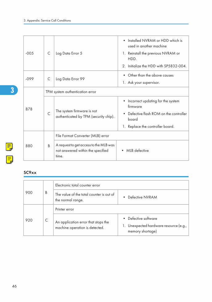
-005 C Log Data Error 5
• Installed NVRAM or HDD which isused in another machine
1. Reinstall the previous NVRAM orHDD.
2. Initialize the HDD with SP5832-004.
-099 C Log Data Error 99• Other than the above causes
1. Ask your supervisor.
878
TPM system authentication error
CThe system firmware is notauthenticated by TPM (security chip).
• Incorrect updating for the systemfirmware
• Defective flash ROM on the controllerboard
1. Replace the controller board.
880 B
File Format Converter (MLB) error
A request to get access to the MLB wasnot answered within the specifiedtime.
• MLB defective
SC9xx
900 B
Electronic total counter error
The value of the total counter is out ofthe normal range.
• Defective NVRAM
920 C
Printer error
An application error that stops themachine operation is detected.
• Defective software
1. Unexpected hardware resource (e.g.,memory shortage)
3. Appendix: Service Call Conditions
46
3

921 C
Printer font error
A necessary font is not found in the SDcard when the printer application starts.
• A necessary font is not found in the SDcard.
• The SD card data is corrupted.
1. Check that the SD card stores correctdata.
925
Net file error
C
The management file for net files iscorrupted; net files are not normallyread.
Netfiles: Jobs to be printed from thedocument server using a PC and theDeskTopBinder software
• Defective hardware
• Data corruption
• Defective software
990 B
Software performance error
The software attempted to perform anunexpected operation.
• When this error occurs, the filename, address, and data will bestored in NVRAM. Thisinformation can be checked byusing SP7-403. See the data andthe situation in which this SCoccurs. Then report the data andconditions to your technicalcontrol center.
• Software defective
• Internal parameter incorrect
• Insufficient working memory
991 D
Software continuity error
The software attempted to perform anunexpected operation. However,unlike SC990, the process can keep onrunning.
• Logged only; the machine cancontinue to operate
992 B
Undefined error
An error not controlled by the systemoccurred (the error does not comeunder any other SC code).
• Defective software program
SC Tables (F/SPF: D068/D069)
47
3

997 C
Application function selection error
The application selected by a key presson the operation panel does not start orends abnormally.
• Software for that application isdefective
• An option required by the application(RAM, DIMM, board) is not installed.
• Too complicated nest of the fax groupaddress
1. As for the fax operation problem,simplify the nest of the fax groupaddress.
998 B
Application start error
After switching the machine on, theapplication does not start within 60 s.(No applications start or end normally.)
• Software for that application isdefective
• An option required by the application(RAM, DIMM, board) is not installed.
1. Check the setting of SP5875-001. Ifthe setting is set to "1 (OFF)", changeit to "0 (OFF)".
3. Appendix: Service Call Conditions
48
3

SC Tables (Basic: D067/D072)
Summary
There are four levels of service call conditions.
Level Definition Reset Procedure
ATo prevent possible damage, the machine does notoperate until the service representative resets the SCcode.
Activate the SP mode, and turn themain power switch off and on.
BTurning the main power stitch off and on resets the SCcode if the error is caused by incorrect sensor detection.
Turn the main power switch off andon.
CThe machine operates as usual excluding the unitrelated to the service call.
Turn the main power switch off andon.
DThe SC history is updated. The machine operates asusual.
No SC code is displayed. Only theSC history is updated.
• If a problem involves circuit boards, see if you can solve the problem by disconnecting andreconnecting all connectors before deciding to replace a circuit board.
• If a problem involves a motor lock, check the mechanical load before deciding to replace a motoror sensor.
• If working on a fax-equipped machine, switching power off and on may cause loss of data stored inthe memory.
SC Tables (Basic: D067/D072)
49
3

Engine SC Code Descriptions
No.Definition
Symptom Possible Cause
101 B
Exposure Lamp Error
The scanner has scanned the white plate,but cannot detect the white level.
• Defective exposure lamp
• Defective exposure lamp stabilizer
• Defective exposure lamp connector
• Unclean scanner mirror
• Scanner mirror out of position
• Defective SBU board
• Defective SBU connector
• Lens block out of position
• Incorrect position or width of whiteplate scanning ( SP4-015)
120 B
Scanner home position error 1
The scanner home position sensor does notdetect the scanner leaving the homeposition.
• Defective scanner home positionsensor
• Defective scanner drive motor
• Defective scanner home positionsensor connector
• Defective scanner drive motorconnector
• Defective BICU board
121 B
Scanner home position error 2
The scanner home position sensor does notdetect the scanner coming back to thehome position.
• Defective scanner home positionsensor
• Defective scanner drive motor
• Defective scanner home positionsensor connector
• Defective scanner drive motorconnector
• Defective BICU board
3. Appendix: Service Call Conditions
50
3

No.Definition
Symptom Possible Cause
141 B
SBU black level correction error
• The automatic SBU adjustment hasfailed to correct the black level threetimes at the pre-offset adjustment.
• The automatic SBU adjustment hasfailed to correct the black level tentimes at the PGA adjustment.
• The automatic SBU adjustment hasfailed to correct the black level tentimes at the offset adjustment.
• Defective SBU board
142 B
SBU white/black level correction error
The automatic SBU adjustment has failedto correct the white level ten times at thePGA adjustment.
• Defective exposure lamp
• Unclean white plate
• Incorrect position or width of whiteplate scanning ( SP4-015)
• Defective SBU board
144 B
Communication Error between BICU and SBU
The BICU cannot correctly establishcommunication with the SBU.
• Loose connection of the flat cablebetween the BICU and the SBU
• Defective flat cable between the BICUand the SBU
• Defective BICU
• Defective SBU
145 D
Automatic SBU adjustment error
The white levels of the white plate and thewhite paper are extraordinarily differentduring the Scan Auto Adjustment (SP4-428-001).
• Defective exposure lamp
• Unclean white plate
• Incorrect position or width of whiteplate scanning ( SP4-015)
• Defective BICU board
• Defective SBU board
SC Tables (Basic: D067/D072)
51
3

No.Definition
Symptom Possible Cause
193 B
Image transfer error
Scanned images are not transferred to thecontroller memory within one minute.
• Defective BICU board
• Defective controller board
198 B
Memory address error
The BICU does not receive the memoryaddress report from the controller withinone minute.
• Inconsistency between the BICUfirmware and the controller firmware
• Defective BICU
• Defective controller
302 B
Charge roller current leak
The polling module detects a current leakof the charge roller.
• Defective charge roller
• Defective high voltage supply board
• Loose connection of the PCU
320 B
Polygonal mirror motor error
The polygon mirror motor does not reachthe operating speed within 10 seconds.Or, the polygon mirror motor remains outof the operating speed for 0.2 second afterreaching the operating speed.
• Defective polygon mirror motor
• Loose connection between thepolygonal mirror motor and the BICU
• Defective cable between the BICUand the polygon mirror motor
• Defective BICU
321 B
No laser writing signal (F-GATE) error
The poling module does not detect the laserwriting signal (F-GATE) asserting after thelaser crosses 5 mm from the start point onthe drum surface.
• Defective BICU
• Loose connection on the fax controlleror the printer controller
• Defective fax controller or printercontroller
3. Appendix: Service Call Conditions
52
3

No.Definition
Symptom Possible Cause
322 B
Laser synchronization error
The main scan synchronization detectordoes not detect the laser signal for 0.5second.
• Toner bottle not installed
• Loose connection between the LD unitand the BICU
• Defective cable between the BICUand LD unit
• LD unit out of position
• Defective LD unit
• Defective BICU
390 B
TD sensor error
The BICU detects the TD sensor outputtingextraordinary voltage (less than 0.2 V ormore than 4.0 V) 10 times consecutively.
• Defective TD sensor
• Loose connection of the PCU
391 B
Development bias leak
The polling module detects a current leakof the development bias.
• Loose connection of the PCU
• Defective high voltage supply board
392 B
Developer initialization error
The ID sensor does not detect a correctpattern during developer initialization (2-214-001).
• Defective ID sensor
• Insufficient developer
• Defective drum operation
• Defective development rolleroperation
• Loose connection of the PCU
• Insufficient voltage for the chargeroller
SC Tables (Basic: D067/D072)
53
3

No.Definition
Symptom Possible Cause
401 B
Transfer roller leak error (positive electrode)
The feedback voltage of the transfer rolleris insufficient.
• Defective high voltage supply board
• Loose connection of the PCU
• Incorrect installation of the transferunit or the separation unit
• Defective transfer roller
402 B
Transfer roller leak error (negative electrode)
The feedback voltage of the transfer rolleris insufficient.
• Defective high voltage supply board
• Loose connection of the PCU
• Incorrect installation of the transferunit or the separation unit
• Defective transfer roller
500 B
Main motor error
The main motor does not reach itsoperation speed within 0.7 second. Or, themain motor remains out of its operationspeed for 0.7 second after reaching theoperation speed.
• Overload
• Defective main motor
541 A
Fusing thermistor open error
The fusing temperature remains lower thanthe specified temperature by 20 degreesCelsius.
• Defective thermistor
• Incorrect installation of the thermistor
• Defective power supply unit
• Loose connectors
542 A
Fusing temperature warm-up error
The fusing temperature rises 7 degrees orless in two seconds; and this continues 5times consecutively. Or, the fusingtemperature is not detected within 25 or 35seconds.
• Defective thermistor
• Incorrect installation of the thermistor
• Defective fusing lamp
• Defective power supply unit
3. Appendix: Service Call Conditions
54
3

No.Definition
Symptom Possible Cause
543 A
Fusing overheat error 1
The fusing temperature detected by thethermistor is 230°C or higher for onesecond.
• Defective thermistor
• Defective power supply unit
544 A
Fusing overheat error 2
The fusing temperature detected by themonitor circuit is 250°C or higher for onesecond.
• Defective thermistor
• Defective power supply unit
545 A
Fusing lamp overheat error
After the fusing temperature reaches thetarget, the fusing lamp remains on for 12seconds.
• Defective thermistor
• Incorrect installation of the thermistor
• Defective power supply unit
546 A
Unstable fusing temperature
While the fusing lamp is on, the fusingtemperature varies 50°C or more withinone second; and this occurs twoconsecutive times.
• Defective thermistor
• Incorrect installation of the thermistor
• Defective power supply unit
547 B
Zero cross signal malfunction
The zero cross signal is not detected withinfive seconds after the main power switch isturned on. Or, the zero cross signal is notdetected within one second after operationbegins.
• Defective power supply unit
• Defective BICU
559 A
Consecutive fusing jam
The paper jam counter for the fusing unitreaches 3 times. The paper jam counter iscleared if the paper is fed correctly.
This SC is activated only whenSP1159-001 is set to "1" (default "0").
• Paper jam in the fusing unit.
SC Tables (Basic: D067/D072)
55
3

No.Definition
Symptom Possible Cause
590 B
Exhaust fan motor error
The exhaust fan motor is locked for fiveseconds.
• Loose connection of the exhaust fanmotor
• Overload
632 C
Accounting error 1
An error occurs during communication withthe MF accounting device.
• Defective accounting device
• Loose connection
634 C
Accounting RAM error
An error occurs in the backup RAM for theMF accounting device.
• Defective accounting device
635 C
Accounting battery error
An error occurs in the battery of the MFaccounting device.
• Defective accounting device
692 C
Printer board communication error
• BICU does not get a signal from theprinter board for 1.5 seconds ormore.
• BICU gets a break-signal aftercompleting the communication withthe printer board and does not get asignal from the printer board for 10seconds or more.
• Defective communication betweenBICU and printer board
694 C
Scanner board communication error
• BICU does not get a signal from thescanner board for 1.5 seconds ormore.
• BICU gets a break-signal aftercompleting the communication withthe scanner board and does not get asignal from the scanner board for 10seconds or more.
• Defective communication betweenBICU and scanner board
3. Appendix: Service Call Conditions
56
3

No.Definition
Symptom Possible Cause
760 B
ADF gate error 1
The ADF sends the FGATE signal before itis requested to scan originals.
• Defective ADF board
• Defective input/output board
• Loose connection
761 B
ADF gate abnormal 2
The ADF does not send the FGATE signalwithin 30 seconds after the ADF startsscanning.
• Defective ADF connector
• Defective SBU board
762 B
ADF gate abnormal 3
The ADF continues to send the FGATEsignal for more than 60 seconds after theADF starts scanning.
• Defective ADF connector
• Defective SBU board
901 B
Mechanical total counter error
The polling module does not detect themechanical total counter.
• Defective mechanical total counter
• Defective BICU
• Loose connection
903 B
Engine total counter error
The checksum of the total counter is notcorrect.
• Defective NVRAM on the BICU
928 B
Memory error
An error occurs during the memory checkconducted when the main power switch isturned on or when the copier is recoveringfrom the energy saver mode.
• Defective memory
• Defective BICU
• Loose connection between the BICUand the memory
929 B
IMAC hardware error
A memory control job is not completedwithin a certain period.
• Defective IMAC
• Defective BICU
• Loose connection
SC Tables (Basic: D067/D072)
57
3

No.Definition
Symptom Possible Cause
981 B
NVRAM error
An error occurs during engine NVRAMcheck.
• Defective NVRAM
• Loose connection between the BICUand the NVRAM
• Incorrect installation of the NVRAM
• Defective BICU
982 B
Localization error
The localization information in thenonvolatile ROM and in the NVRAM isdifferent ( SP5-807-001).
• Localization setting not specified (Themain power switch is turned on for thefirst time after the NVRAM isreplaced.)
• Incorrect localization setting
• Defective NVRAM
3. Appendix: Service Call Conditions
58
3

4. Appendix: Electrical ComponentDefects
Electrical Component Defects
Sensor/Switch
Sensor Connector Message Remarks
Registration SensorCN127
Paper jam -SN
Paper End SensorCN129
Load paper -SN
Bypass Paper EndSensor
CN130(None)
The machine cannot detect paper onthe bypass tray.SN
Paper Path SensorCN128
Paper jam -SN
Exit SensorCN128
Paper jam -SN
Image Density (ID)Sensor
CN132(None) Print quality may become worse.
SN
Toner Density (TD)Sensor
CN123 SC901The connector is shared with themechanical total counter.
PCU Reset PCU correctly -
Scanner HP SensorCN126 SC120 -
SN SC120 -
59
4

Sensor Connector Message Remarks
Platen Cover Sensor
CN126 SC120 -
SN (None)The copier does not warm up whenyou open the platen cover.
DF Guide OpenSensor
DF CN103 Paper jam -
SN (None) -
DF Original SetSensor
DF CN103 Paper jam -
Sensor (None) Originals are not detected.
DF RegistrationSensor
DF CN103Paper jam
-
SN Originals are correctly transported.
Inverter SensorDF CN103 Paper jam -
SN (None) -
Exit SensorDF CN103
Paper jam-
SN -
Front Door Switch
CN114 Right door open -
SW Front/Right door openThe message depends on whichcircuit is open (white → front; blue→ right).
Right Door SwitchCN114 Right door open -
SW Right door open -
CNxxx: The connector on the BICU board.
DF CNxxx: The connector on the DF connection board.
SN: The connector on the sensor.
SW: The connector on the switch.
PCU: The connector on the PCU.
Blown Fuse Conditions
All of these fuses are on the power supply unit.
4. Appendix: Electrical Component Defects
60
4

FuseRating
At main switch ON120 V 220 – 240 V
FU1 15A/125V 8A/250 V No response
FU2 5A/125V 2.5A/250V No response
BICU LED Display
Number Function
LED2 LED2 blinks in normal operation.
Electrical Component Defects
61
4

4. Appendix: Electrical Component Defects
62
4

5. Appendix: SP Mode Tables
System Service Mode (F/SPF: D068/D069)
Service Mode Tables
SP1-XXX (Feed)
1001* LE Registration [–9.0 to 9.0 / 0.0 / 0.1 mm/step]
1001 1 All TraysAdjusts the leading-edge registration ( "AdjustingCopy Image Area" in the section "Replacement andAdjustment").
1001 2 By-pass
1001 3 Duplex
1002* S-to-S Regist [–9.0 to 9.0 / 0.0 / 0.1 mm/step]
1002 1 1st TrayAdjusts the side-to-side registration ( "Adjusting CopyImage Area" in the section "Replacement andAdjustment"). SP1-002-001 is applied to all trays.SP1-002-002, 003 and 005 adjusts the differencefrom SP1-002-001.
1002 2 2nd Tray
1002 3 3rd Tray
1002 5 By-pass
1002 6 DuplexAdjusts the side-to-side registration of the 2nd side induplex copying. The 1st side is adjusted bySP1-002-001 through 005.
1003* Paper Feed TimingAdjusts the amount of paper buckle on the registrationroller.
1003 1 1st tray [0 to 10 / 5 / 1 mm/step]
1003 3 Bank Trays [0 to 10 / 5 / 1 mm/step]
1003 4 By-pass [0 to 10 / 5 / 1 mm/step]
1003 5 Duplex [0 to 20 / 5 / 1 mm/step]
63
5

1103* Fusing Idling [0 = No / 1 = Yes]
1103 1
Enables or disables the contact-release control. The following table lists the results.
Setting 0 = No 1 = Yes
C-R control Works Does not work
Idling time Shorter Longer
Fusing quality Lower Higher
1105*
Fusing Temp Adj
Adjusts the target fusing temperature. Note that the thermistor is at the center of the hotroller.
1105 1 Warm Up-Center [140 to 180 / 160 / 1°C/step]
1105 3 Standby-Center [140 to 160 / 150 / 1°C/step]
1105 5 Copying-Center [140 to 180 / 160 / 1°C/step]
1105 7 Low Level 2-Center [0 to 80 / 60 / 1°C/step]
1105 9 Thick-Center [140 to 185 / 165 / 1°C/step]
1106 Display Fusing
1106 1 (Center) Displays the fusing temperature.
1107*
Fusing Soft Start DFU
Adjusts the number of zero-cross cycles of the fusing lamp AC supply needed to bring thefusing lamp power to 100% while bringing the lamp up to the standby temperature or whilecopying. Increase this value if the machine is experiencing sudden power dropouts.
1107 1 Warm Up Soft Start [0 = 10 times / 1 = 20 times / 2 = 50 times]
1107 2 Other Soft Start [0 = 10 times / 1 = 20 times / 2 = 50 times / 3 = 1 time]
1107 3 Soft Stop Setting [0: No / 1: Yes]
1108* Set-Fusing Start [0 = 1s / 1 = 1.5s / 2 = 2s]
1108 1 Specifies the interval for fusing-temperature control.
5. Appendix: SP Mode Tables
64
5

1109 Nip Band Check
1109 1Conducts the nip band check ( "Adjusting Nip Band" in the section "Replacement andAdjustment").
1110* Fan Control Timer [30 to 60 / 30 / 1 s/step]
1110 1Specifies the fan control time. The fan motor keeps its operating speed for the specifiedtime before changing the speed or stopping. The fan control timer prevents the exhaust fanfrom suddenly stopping. This function protects the copier from overheating.
1159* Fusing Jam SC [0 = No / 1 = Yes]
1159 1Enables or disables consecutive jam detection at the fusing unit. If this SP is set to "1" (default:0), consecutive fusing jam alarm occurs (SC559) when the machine detects threeconsecutive paper jams at the fusing unit.
1902 Display-AC Freq.
1902 1Displays the fusing lamp power control frequency (as detected by the zero cross signalgenerator). The displayed value is 1/5 the actual frequency: 10 and lower = 50 Hz, 11and higher = 60 Hz.
1911* By-pass Envelope [0 = No / 1= Yes]
1911 1The program dedicated to envelope printing runs when you enable this program(SP1-911-001) and you select “Thick Paper” as the paper type of the by-pass tray( > System Settings > Tray Paper Settings > Paper Type: Bypass Tray).
SP2-XXX (Drum)
2001* CR Bias Adj
2001 1
Printing [–2100 to –1500 / –1650 / 1 V/step]
Adjusts the voltage applied to the charge roller for printing. The voltage changesautomatically as charge-roller voltage control works. The value here is the base value forthe charge-roller voltage control.
System Service Mode (F/SPF: D068/D069)
65
5

2001 2
ID sensor pattern [0 to 400 / 300 / 1 V/step]
Adjusts the voltage applied to the charge roller for the ID sensor pattern (as part of charge-roller voltage correction). The charge-roller voltage is obtained by adding SP2-001-002to the value of SP2-001-001.
2101* Erase Margin AdjAdjusts the width of the erased area ( "Adjusting CopyImage Area" in the section "Replacement andAdjustment").
2101 1 Leading Edge[0.0 to 9.0 / 3.0 / 0.1 mm/step]
Specification: 2 ± 1.5 mm
2101 2Trailing Edge
[0.0 to 9.0 / 4.0 / 0.1 mm/step]
Specification: 2 +2.5/–1.5 mm
The rear trailing edge is this value plus 1.2 mm.
2101 3Left side
[0.0 to 9.0 / 2.0 / 0.1 mm/step]
Specification: 2 ± 1.5 mm
The rear left edge is this value plus 0.3 mm.
2101 4Right side
[0.0 to 9.0 / 2.0 / 0.1 mm/step]
Specification: 2 +2.5/–1.5 mm
The rear right edge is this value plus 0.3 mm.
2201* Dv Bias Adj
2201 1
Printing [–1500 to –200 / –650 / 1 V/step]
Adjusts the voltage applied to the development roller for printing. Image density becomeshigher when you specify a smaller value (a greater absolute value). Image density becomeslower when you specify a greater value (a smaller absolute value).
2201 2
ID sensor pattern[–2 = LL (220 V) / -1 = L (260 V) / 0 = N (300 V) / 1= H (340 V) / 2 = HH (380 V)]
Adjusts the voltage applied to the development roller for the ID sensor pattern. The voltageapplied is obtained by adding SP2-201-002 to SP2-201-1. The setting affects ID sensorpattern density, which in turn affects the toner supply.
5. Appendix: SP Mode Tables
66
5

2213* Outputs After NE
2213 1
[0 = 50 pages / 1 = 20 sheets]
Sets the number of copy/print/fax pages that can be made after toner near-end has beendetected. Reduce the number of pages if the user normally makes copies with a high imageratio.
2214 Develpr Initialize
2214 1Initializes the TD sensor toner supply target voltage and the TD sensor gain value. Executethis SP replacing the developer or the TD sensor.
2221 ID Error Analysis ( "ID Sensor Error Analysis (SP2-221)")
2221 1 Vsg Displays the Vsg value.
2221 2 Vsp Displays the Vsp value.
2221 3 PWM Displays the PWM value.
2221 4 Vsdp Displays the Vsdp value.
2221 5 Vt Displays the Vt value.
2221 6 Vts Displays the Vts value.
2301* Tr Current Adj ( "Image Transfer Current").
2301 1
Normal paper[–2 = –4 μA / –1 = –2 μA / 0 = 0 μA / 1 = 2 μA / 2= +4 μA]
Adjusts the current applied to the transfer roller when feeding from a paper tray. Use ahigh setting if the user normally feeds relatively thick paper (within spec) from a paper tray
2301 2
Thick/Special[–2 = –4 μA / –1 = –2 μA / 0 = 0 μA / 1 = 2 μA / 2= +4 μA]
Adjusts the current applied to the transfer roller when feeding from the by-pass tray. Usea high setting (a) if the user normally feeds relatively thick paper from the by-pass tray, or(b) if waste toner is re-attracted from the drum (which can occur when using transparencies).
System Service Mode (F/SPF: D068/D069)
67
5

2301 3
Duplex[–2 = –4 μA / –1 = –2 μ/ 0 = 0 μA / 1 = 2 μA / 2 =+4 μA]
Adjusts the current applied to the transfer roller when carrying out a duplex job. Use thisSP if there is poor image transfer on the rear side of duplex copies.
2301 4
Cleaning [–10 to 1 / –1 / 1 μA/step]
Adjusts the current applied to the transfer roller for roller cleaning. Increase the current iftoner remains on the roller after cleaning. (Remaining toner may cause dirty backgroundon the rear side.)
2802 Forced Develpr Churn
2802 1
Initializes the developer and checks the TD sensor output (Vt). The machine mixes thedeveloper for 2 minutes while reading and displaying the Vt value. The machine does notinitialize the TD sensor output. If the machine has not been used for a long period, printsmay have a dirty background. In a case like this, use this SP to mix the developer. Themessage “Completed” is displayed when the program ends normally.
2906* Tailing Crctn
2906 1
Shift value [0.0 to 1.0 / 0.0 / 0.1 mm/step]
Shifts the image position at the intervals specified by SP2-906-002. When the copier iscontinuously printing vertical lines (such as in tables), the paper may not separate correctly.This SP can prevent this.
2906 2Interval [1 to 10 / 1 / 1 page/step]
Changes the interval of the image position shift specified by SP2-906-001.
2908 Forced Toner Supp
2908 1
Supplies the toner to the development unit. The processing stops under either of thefollowing conditions:
• The toner density in the development unit reaches the standard level.
• The processing has continued for two 2 minutes.
2915* Polygon Idling [0 = None / 1 = 15 s / 2 = 25 s]
5. Appendix: SP Mode Tables
68
5

2915 1
Specifies the polygon mirror motor idling time. The polygon mirror motor starts its operationwhen an original is set, a key is pressed, or the platen cover or DF is opened. The motorstops if no manual operation is performed for the specified time. When you set “0”, themotor does not stop while the copier is in the standby status.
2921* Toner Supply Mode
2921 1[0 = Sensor 1 / 1 = Sensor 2 (DFU)]
Selects the toner supply mode. Keep the default setting as long as the TD sensor is working.
2922* Toner Supply Time [0.1 to 5.0 / 0.6 / 0.1 s/step]
2922 1Adjusts the toner supply time. The toner supply motor remains on for the specified time. Tovalidate this setting, select “0” in SP2-921-001. Specify a greater value if the user tendsto make many copies having high proportions of solid black image areas.
2926* Standard Vt [0.00 to 5.00 / 2.50 / 0.01 V/step] DFU
2926 1Adjusts Vts (the Vt value for new developer). The TD sensor output is adjusted to this valueduring the TD sensor initial setting process. This SP is effective only when SP2-921001 is“0”, “1”, or “2”.
2927* ID Sensor Control [0 = No / 1 = Yes]
2927 1Determines whether the ID sensor signal is referenced or not for the toner density control.Keep the default value in usual operations.
2928 Toner End Clear
2928 1
Clears the following messages and counters without supplying the toner:
• Toner near end message
• Toner end message
• Toner near end counter
• Toner end counter
Do not use this SP in usual operations. When the toner in the development unit is abnormallyinsufficient, the drum may attract the toner carrier to its surface. The toner carrier damagesthe drum surface..
2929* Vref Limits Adjust the upper or lower Vref limit.
System Service Mode (F/SPF: D068/D069)
69
5

2929 1 Upper [0.50 to 3.50 / 3.20 / 0.01V/step] DFU
2929 2 Lower [0.50 to 3.50 / 0.70 / 0.01V/step] DFU
2994* ID Detect Temp [30 to 90 / 30 / 1 °C/step]
2994 1Adjusts the temperature threshold. The ID sensor signal is not referenced when the fusingtemperature is at the specified level or higher while the copier is recovering or starting up.
2996* T Roller Cleaning [0 = No / 1 = Yes]
2996 1Cleans or does not clean the transfer roller before each job. Select “1” if the backside ofthe paper becomes unclean when output. Note that the copier takes a longer time to outputthe first copy when you select “1”. If you select “0”, the transfer roller is never cleaned.
2998* Main Mag- print [–0.5 to +0.5 / 0.0 / 0.1%/step]
2998 1Adjusts the magnification ( "Adjusting Copy Image Area" in the section "Replacementand Adjustment"). The specification is 100 ± 1.0%.
SP4-XXX (Scanner)
4008* SubScan Mag (Scanner) [-0.9 to +0.9 / 0.0 / 0.1%/step]
4008 1Adjusts the sub-scan magnification ( "Adjusting Copy Image Area" in the section"Replacement and Adjustment").
4009* Main Scan Mag (Scanner) [–0.9 to +0.9 / 0.0 / 0.1%/step]
4009 1Adjusts the main-scan magnification ( "Adjusting Copy Image Area" in the section"Replacement and Adjustment").
4010* LE Scan Regist [–5.0 to +5.0 / 0.0 / 0.1 mm/step]
4010 1Adjusts the leading edge registration ( "Adjusting Copy Image Area" in the section"Replacement and Adjustment").
4011* S-to-S Scanner Registration [–2.0 to +2.0 / 0.0 / 0.1 mm/step]
5. Appendix: SP Mode Tables
70
5

4011 1Adjusts the side-to-side registration for scanning in platen mode ( "Adjusting Copy ImageArea" in the section "Replacement and Adjustment").
4012* Scan Erase Margin [0 to 9.0 / 1.0 / 0.1 mm/step]
4012 1 Leading Edge
Adjusts the scanning margin. Generally, the scanningmargin should be as little as possible. To adjust the imagearea, use SP2-101.
4012 2 Trailing Edge
4012 3 Left Side
4012 4 Right Side
4013 Scanner Free Run
4013 1 Conducts the scanner free run with the exposure lamp on.
4015* White Plate Scan
4015 1
Start position [–3.0 to +6.0 / 0.0 / 0.1 mm/step]
Adjusts the scanning start position on the white plate. The base value is 17.8 mm from thescanner home position. This SP specifies the offset from this base value.
4015 2
Scanning Length [–3.0 to +6.0 / 0.0 / 0.1 mm/step]
Adjusts the distance of the white plate scan. The scan begins from the start position(SP4-015-001) and ends at the specified distance. The base value is 2.0 mm. This SPdecides the offset from this base value. Specify 0 (zero) or a larger value.
4428 Scan Auto Adj
4428 1Conducts the automatic scanner adjustment. Use this SP after replacing the white plate( "Scanning" in the section "Replacement and Adjustment").
4606 SBU Offset-Target
System Service Mode (F/SPF: D068/D069)
71
5

4607 1 EVEN
[0 to 63 / 10 / 1 /step]
Adjusts the target black level for each signal.
These are used for offset adjustment in the SBU.
4607 2 ODD
4607 3 RED
4607 4 GREEN
4607 5 BLUE
4607 SBU Gain-Target
4607 1 EVEN
[0 to 255 / 180 / 1 /step]
Adjusts the target white level for each signal.
These are used for gain adjustment in the SBU.
4607 2 ODD
4607 3 RED
4607 4 GREEN
4607 5 BLUE
4623 SBU Offset-Result
4623 1 EVEN
[0 to 255 / 0 / 1 /step]
Displays the result value of the offset adjustment in theSBU.
4623 2 ODD
4623 3 RED
4623 4 GREEN
4623 5 BLUE
4628 SBU Gain-Result
4628 1 EVEN
[0 to 255 / 0 / 1 /step]
Displays the result value of the gain adjustment in the SBU.
4628 2 ODD
4628 3 RED
4628 4 GREEN
4628 5 BLUE
5. Appendix: SP Mode Tables
72
5

4640 SBU Offset-Loop
4640 1 EVEN
[0 to 10 / 0 / 1 /step]
Displays the number of the offset adjustment in the SBU.
4640 2 ODD
4640 3 RED
4640 4 GREEN
4640 5 BLUE
4641 SBU Gain-Loop
4641 1 EVEN
[0 to 10 / 0 / 1 /step]
Displays the number of the gain adjustment in the SBU.
4641 2 ODD
4641 3 RED
4641 4 GREEN
4641 5 BLUE
4642 SBU Offsetpre-Loop
4642 1 EVEN
[0 to 3 / 0 / 1 /step]
Displays the number of the pre-offset adjustment in theSBU.
4642 2 ODD
4642 3 RED
4642 4 GREEN
4642 5 BLUE
4646 SBU Adj Error
System Service Mode (F/SPF: D068/D069)
73
5

4646 1 Offsetpre-Mono
[0 = Success / 1 = Failure]
Displays the result of SBU adjustment.
4646 2 Offsetpre-Color
4646 3 Offset-Mono
4646 4 Offset-Color
4646 5 Gain-Mono
4646 6 Gain-Color
4654* SBU Offset-Adjust
4654 1 EVEN
[0 to 255 / - / 1 /step]
Displays the offset value of the offset adjustment in theSBU.
4654 2 ODD
4654 3 RED
4654 4 GREEN
4654 5 BLUE
4658* SBU Gain-Adjust
4658 1 EVEN
[0 to 511 / - / 1 /step]
Displays the gain value of the gain adjustment in the SBU.
4658 2 ODD
4658 3 RED
4658 4 GREEN
4658 5 BLUE
4685* Gray Balance-Book
4685 1 RED[128 to 383 / 256 / 1 /step]
Adjusts the coefficient of the gray balance adjustment forthe book scanning.
4685 2 GREEN
4685 3 BLUE
4686* Gray Balance-DF
5. Appendix: SP Mode Tables
74
5

4686 1 RED[128 to 383 / 256 / 1 /step]
Adjusts the coefficient of the gray balance adjustment forthe DF scanning.
4686 2 GREEN
4686 3 BLUE
4687* White Balance
4687 1 Adjust[222 to 281 / 256 / 1 /step]
Adjust the correction value for the white plate adjustment.
4687 2 ResultDisplays the current value of the white plate adjustment.
If SP4-428 has not been done, this value is "0".
4690 White Peek Init
4658 1 EVEN
[0 to 255 / - / 1 /step]
Displays the white offset value of the pre-offset adjustmentin the SBU.
4658 2 ODD
4658 3 RED
4658 4 GREEN
4658 5 BLUE
4693 Black Ave Init
4658 1 EVEN
[0 to 255 / - / 1 /step]
Displays the black offset value of the pre-offsetadjustment in the SBU.
4658 2 ODD
4658 3 RED
4658 4 GREEN
4658 5 BLUE
4902* Exposure Lamp ON [0: OFF / 1: ON]
4902 1Turns the exposure lamp on or off. To turn on the exposure lamp, specify “1”; to turn it offspecify “0”.
4903* ADS Level [0 to 255 / 252 / 1/step]
System Service Mode (F/SPF: D068/D069)
75
5

4903 1 Adjusts the ADS level.
4904* ADS Lower Limit [0 to 255 / 80 / 1/step]
4904 1 Adjusts the ADS lower limit.
4905* ADS Area Select [0 = All / 1 = One]
4905 1
Checks the whole area (0 = All) or the specific areas (1 = One) to adjust the ADS level.The specific areas are as follows:
• ARDF: ±37.5 mm from the center
• Platen Cover: 15 to 90 mm from the left edge
4921* Image Adj Selec
001
Copy [0 to 10 / 0 / 1]
Selects which mode the settings from SP4-922 to SP4-932 are used for.
0 = None, 1 = Text 1, 2 =Text 2, 3= Photo 1, 4 = Photo 2, 5 = Photo 3, 6 = Special 1, 7= Special 2, 8 = Special 3, 9 = Special 4,
10 = Special 5
002
Fax [0 to 5 / 0 / 1]
Selects which mode the settings from SP4-922 to SP4-932 are used for.
0 = None, 1 = Text 1, 2 = Text 2, 3 = Photo 1, 4 = Photo 2,
5 = Special 1
003
Scanner (Mono) [0 to 4 / 0 / 1]
Selects which mode the settings from SP4-922 to SP4-932 are used for.
0 = None, 1 = Text 1, 2 = Text 2, 3= Photo 1, 4 = Photo 2
004
Scanner (Color) [0 to 2 / 0 / 1]
Selects which mode the setting of SP4-935 is used for.
0 = None, 1 = Color Text, 2 = Color Photo
005
Scanner (Gray Scale) [0 or 1 / 0 / - ]
Selects which mode the setting of SP4-936 is used for.
0 = None, 1 = Gray Scale
5. Appendix: SP Mode Tables
76
5

4922*
Scanner Gamma
Selects “text” or “photo” as the priority output mode. This setting is applied to all imageprocessing modes of SP4-921.
001 Copy
[0=System default/ 1=Text/ 2=Photo]002 Fax
003 Scanner
4923*
Notch Selection
Selects the value of the center ID adjustment notch for the ID adjustment LEDs.
• Normally the center notch is 3 (range 1-5). If –1 is selected, each notch shifts down(becomes lighter). If +1 is selected, each notch shifts up (becomes darker).
• This setting is applied to all image processing modes of SP4-921.
001 Copy
[–1 = Light / 0 = Normal / +1 = Dark]002 Fax
003 Scanner
4926*
Texture Removal
Adjusts the texture removal level that is used with error diffusion. 0: The default value foreach mode is used. Text 1, Photo 2, Special 2, and Special 5 have a default of 3 andPhoto 1-3 have a default of 1.
1: No removal applied.
2 to 5: Removal applied at the level specified here. The higher the setting (level), the lessclear the image will become (more texture removal). This setting is only applied to theoriginals in SP4-921.
001 Copy
[0 to 6 / 0 / 1/step]002 Fax
003 Scanner
4927*
Line Width
Adjusts the line width correction algorithm. Positive settings produce thicker lines; negativesettings produce thinner lines. This setting is only applied to the originals in SP4-921.
System Service Mode (F/SPF: D068/D069)
77
5

001 Copy
[–2 to 2 / 0 / 1/step]002 Fax
003 Scanner
4928*
Independent Dot Erase
Selects the dot erase level. Higher settings provide greater erasure. This setting is onlyapplied to the originals in SP4-921.
001 Copy
[–2 to 2 / 0 / 1/step]002 Fax
003 Scanner
4929*Positive/Negative [0 = No, 1 = Yes]
Inverts white and black. This setting is only applied to the originals in SP4-921.
001 Copy
002 Fax
4930*Sharpness-Edge [–2 to 2 / 0 / 1/step]
Adjust the clarity. This setting is only applied to the originals in SP4-921.
001 Copy
002 Fax
003 Scanner
4931*Sharpness-Solid [–2 to 2 / 0 / 1/step]
Adjust the clarity. This setting is only applied to the originals in SP4-921.
001 Copy
002 Fax
003 Scanner
5. Appendix: SP Mode Tables
78
5

4932*Sharpness-Low ID [–2 to 2 / 0 / 1/step]
Adjust the clarity. This setting is only applied to the originals in SP4-921.
001 Copy
002 Fax
003 Scanner
4935* Color Image Adjust
001
Main Scan MTF Level [0 to 3 / 0 / 1/step]
Adjust the MTF level for the main scan. This setting is only activated for the specified modewith SP4-921-004.
0: None, 1: Weak, 2: Middle, 3: Strong
002
Main Scan MTF Strength [0 to 5 / 0 / 1/step]
Adjust the MTF strength for the main scan. This setting is only activated for the specifiedmode with SP4-921-004.
0: 1, 1: 1/32, 2: 1/16, 3: 1/8, 4: 1/4, 5: 1/2
003
Sub Scan MTF Level [0 or 1 / 0 / 1/step]
Turns on or off the MTF for the sub scan. This setting is only activated for the specified modewith SP4-921-004.
0: No, 1: Yes
004
Sub Scan MTF Strength [0 to 5 / 0 / 1/step]
Adjust the MTF strength for the sub scan. This setting is only activated for the specified modewith SP4-921-004.
0: 1, 1: 1/32, 2: 1/16, 3: 1/8, 4: 1/4, 5: 1/2
005
Smooth Level [0 to 2 / 0 / 1/step]
Adjust the smooth level. This setting is only activated for the specified mode withSP4-921-004.
0: None, 1: Weak, 2: Strong
006
Brightness [0 to 255 / 128 / 1/step]
Adjust the brightness level. This setting is only activated for the specified mode withSP4-921-004.
System Service Mode (F/SPF: D068/D069)
79
5

007
Contrast [0 to 255 / 128 / 1/step]
Adjust the contrast level. This setting is only activated for the specified mode withSP4-921-004.
4936* Gray Scale Image Adjust
001
Main Scan MTF Level [0 to 15 / 0 / 1/step]
Adjust the MTF level for the main scan. This setting is only activated for the specified modewith SP4-921-004.
0: None, 1: Level 1 to 15: Level 15
002
Main Scan MTF Strength [0 to 5 / 0 / 1/step]
Adjust the MTF strength for the main scan. This setting is only activated for the specifiedmode with SP4-921-004.
0: 1, 1: 1/32, 2: 1/16, 3: 1/8, 4: 1/4, 5: 1/2
003
Sub Scan MTF Level [0 to 13 / 0 / 1/step]
Adjust the MTF level for the sub scan. This setting is only activated for the specified modewith SP4-921-004.
0: No, 1: Level 1 to 13: Level 13
004
Sub Scan MTF Strength [0 to 5 / 0 / 1/step]
Adjust the MTF strength for the sub scan. This setting is only activated for the specified modewith SP4-921-004.
0: 1, 1: 1/32, 2: 1/16, 3: 1/8, 4: 1/4, 5: 1/2
005
Smooth Level [0 to 7 / 0 / 1/step]
Adjust the smooth level. This setting is only activated for the specified mode withSP4-921-004.
0: None, 1: Level 1 to 7: Level 7
006
Brightness [0 to 255 / 128 / 1/step]
Adjust the brightness level. This setting is only activated for the specified mode withSP4-921-004.
5. Appendix: SP Mode Tables
80
5

007
Contrast [0 to 255 / 128 / 1/step]
Adjust the contrast level. This setting is only activated for the specified mode withSP4-921-004.
4941* White Line Erase [0 to 2 / 1 / 1/step]
4941 1
Selects the white line erase level.
0: None, 1: Weak, 2: Strong
• This setting is effective for all modes.
• 0: White line erase is not used, and white level correction is used instead·
• This setting is applied regardless of what mode has been selected in SP4-921.
4942* Black Line Erase [0 to 3 / 2 / 1/step]
4942 1
Selects the black line erase level. This setting is effective only when originals are scannedby the DF.
[0 = No / 1 = Very weak / 2 = Weak / 3 = Strong]
This setting is applied regardless of what mode has been selected in SP4-921.
4943* WhitePapDetect BiLv
4943 1 Gray Scale [0 to 255 / 64 / 1/step]
4943 1 Color2 [0 to 255 / 128 / 1/step]
4943 1 Color3 [0 to 255 / 128 / 1/step]
SP5-XXX (Mode)
5001 All Indicators On
5001 1Turns on all LEDs. The LCDs turn on and off every 3 seconds. Press the reset key to end thisprogram.
5024* mm/inch Selection
System Service Mode (F/SPF: D068/D069)
81
5

001
Selects whether mm or inches are used in the display.
• After selecting the number, you must turn the main power switch off and on.
Europe/Asia model: [0: mm / 1: inch]
American model: [0: mm / 1: inch]
5045* According Counter
5045 1 Counter Method
Displays the number of the installed counter.
[0 to 2 / 0 / 1 /step]
0: 1 counter (Total)
1: 2 counters (Total and Prints)
2: 2 counters GPC
5055 Display IP address
001 Display IP address CTL
Displays or does not display the IP address on the LCD.
[0 or 1 / 0 / -]
0: No (Not display), 1: Yes (Display)
5056 Coverage Counter
001 Coverage Counter CTL
Displays or does not display the coverage counter onthe LCD.
[0 or 1 / 0 / -]
0: Not display, 1: Display
5062 Part Replacement
001 PCU CTL
Displays or does not display the PCU yield on the LCD.
[0 or 1 / 0 / -]
0: Not display, 1: Display
5066 PM Parts Display
5. Appendix: SP Mode Tables
82
5

001 PM Parts Display CTL
Displays or does not display the PM part button on theLCD.
[0 or 1 / 0 / -]
0: Not display, 1: Display
5067 Part Replacement Ope
001 PCU CTL
Selects the service maintenance or user maintenancefor PCU.
[0 or 1 / 0 / -]
0: Service, 1: User
5113 Optional Counter Type
001 Opt Cnt Type 1 CTL
This program specifies the counter type.
0: None
1: Key card (RK 3, 4)
2: Key card (down)
3 to 10: (Japan only)
11: Exp. Key card (Add)
12: Exp. Key card (Deduct)
002 Opt Cnt Type 2 CTL
This program specifies the external counter type.
0: None
1: Expansion Device type 1
2: Expansion Device type 2
3: Expansion Device type 3
5114 Optional Counter I/F CTL[0: Not installed/ 1: Installed (scanningaccounting)]
001 MF Key Card Ext. Japan use
5118 Disable Copying CTL [0: Not disabled/ 1: Disabled]
001 This program disables copying.
System Service Mode (F/SPF: D068/D069)
83
5

5120* Clr For Cut Remove [0=Yes / 1=Standby only / 2=No]
5120 1
Specifies the condition to reset the copy job settings when the key counter is removed.
• 0: Y = Yes: The settings are cleared when the counter is removed.
• 1: StdBy = Standby only: The settings are cleared when the counter is removed at theend of a job.
• 2: N = No: The settings are not cleared under either condition.
As for duplex copying, the job settings are always preserved regardless of these setting.
5121* Counter Up Timing [0 = Feed In / 1 = Exit]
5121 1
Selects the count-up timing.
• 0 = Feed: At each paper feed
• 1= Exit: At each paper exit
5167
Fax Prnt Cnt Off
Enables or disables the automatic print out without an accounting device. This SP is usedwhen the receiving fax is accounted by an external accounting device.
001 Fax Prnt Cnt Off CTL
[ 0 or 1 / 0 / – ]
0: Automatic printing
1: No automatic printing
5169
CE Login
If you change the printer bit switches, you must ‘log in’ to service mode with this SP beforeyou go into the printer SP mode.
001 CE Login CTL
[0 or 1 / 0 / - ]
0: Disabled
1: Enabled
5188 Copy NV Version
001 Copy NV Version CTL Displays the NVRAM version in the controller board.
5. Appendix: SP Mode Tables
84
5

5302
Set Time
Adjusts the RTC (real time clock) time setting for the local time zone.
Examples: For Japan (+9 GMT), enter 540 (9 hours x 60 min.)
DOM: +540 (Tokyo)
NA :-300 (New York)
EU :+ 60 (Paris)
CH :+480 (Peking)
TW :+480 (Taipei)
AS :+480 (Hong Kong)
002 Time DifferenceCTL
#[-1440 to 1440 / Area / 1 min./step ]
5307 Summer Time
001
ON/OFF -
[ 0 or 1 / NA, EU, ASIA / 1 /step]
0: Disabled
1: Enabled
NA and EUR: 1, ASIA: 0
Enables or disables the summer time mode.
• Make sure that both SP5-307-3 and -4 are correctly set. Otherwise, this SP is notactivated even if this SP is set to "1".
System Service Mode (F/SPF: D068/D069)
85
5

003
Start - -
Specifies the start setting for the summer time mode.
There are 8 digits in this SP. For months 1 to 9, the "0" cannot be input in the first digit, sothe eight-digit setting for -2 or -3 becomes a seven-digit setting.
1st and 2nd digits: The month. [1 to 12]
3rd digit: The week of the month. [1 to 5]
4th digit: The day of the week. [0 to 6 = Sunday to Saturday]
5th and 6th digits: The hour. [00 to 23]
7th digit: The length of the advanced time. [0 to 9 / 1 hour /step]
8th digit: The length of the advanced time. [0 to 5 / 10 minutes /step]
For example: 3500010 (EU default)
The timer is advanced by 1 hour at am 0:00 on the 5th Sunday in March
• The digits are counted from the left.
• Make sure that SP5-307-1 is set to "1".
004
End - -
Specifies the end setting for the summer time mode.
There are 8 digits in this SP.
1st and 2nd digits: The month. [1 to 12]
3rd digit: The week of the month. [0 to 5]
4th digit: The day of the week. [0 to 6 = Sunday to Saturday]
5th and 6th digits: The hour. [00 to 23]
The 7th and 8th digits must be set to "00".
• The digits are counted from the left.
• Make sure that SP5-307-1 is set to "1".
5401Access Control
When installing the SDK application, SAS (VAS) adjusts the following settings. DFU
103 DocAcl CTL
104 Authentication Time CTL [ 0 to 255 / 0 / 1 /step]
5. Appendix: SP Mode Tables
86
5

162 Extend Certification CTL
Selects the log out type for the extendauthentication device.
Bit 0: Log-out without an IC card.
0: Not allowed (default)
1: Allowed
200 SDK1 Unique ID CTL
“SDK” is the “software development kit”.This data can be converted from SAS(VAS) when installed or uninstalled.(DFU)
201 SDK1 Certification Method CTL
210 SDK2 Unique ID CTL
211 SDK2 Certification Method CTL
220 SDK3 Unique ID CTL
221 SDK3 Certification Method CTL
230 SDK Cert CTL
240 Detail Option CTL
Enables or disables the log-outconfirmation option.
Bit0: Log-out confirmation option
0: Enable (default), 1: Disable
Selects the automatic log-out time.
Bit1 and 2: Automatic log-out timerreduction
00: 60 seconds (default), 01:10seconds, 10: 20seconds, 11: 30seconds
5404 User Code Clear
001Clears the counts for the user codes assigned by the key operator to restrict the use of themachine. Press [Execute] to clear.
5411 LDAP Certification
System Service Mode (F/SPF: D068/D069)
87
5

004
Easy Certification
Determines whether easy LDAP certification is done.
[0 to 1/1/1]
1: On
0: Off
005
Password Null Not Permit
This SP is referenced only when SP5411-4 is set to "1" (On).
[0 to 1/0/1]
0: Password NULL not permitted.
1: Password NULL permitted.
5413 Lockout Setting
001
Lockout On/Off
Switches on/off the lock on the local address book account.
[0 to 1/0/1]
0: Off
1: On
002
Lockout Threshold
Sets a limit on the frequency of lockouts for account lockouts.
[1 to 10/5/1]
003
Cancel On/Off
Determines whether the system waits the prescribed time for input of a correct user ID andpassword after an account lockout has occurred.
[0 to 1/0/1]
0: Off (no wait time, lockout not cancelled)
1: On (system waits, cancels lockout if correct user ID and password are entered.
004
Cancel Time
Determines the length of time that the system waits for correct input of the user ID andpassword after a lockout has occurred. This setting is used only if SP5413-3 is set to "1" (on).
[1 to 999/60/1 min.]
5. Appendix: SP Mode Tables
88
5

5414 Access Mitigation
001
Mitigation On/Off
Switches on/off masking of continuously used IDs and passwords that are identical.
[0 to 1/0/1]
0: Off
1: On
002
Mitigation Time
Sets the length of time for excluding continuous access for identical user IDs and passwords.
[0 to 60/15/1 min.]
5415 Password Attack
001
Permissible Number
Sets the number of attempts to attack the system with random passwords to gain illegalaccess to the system.
[0 to 100/30/1 attempt]
002
Detect Time
Sets the time limit to stop a password attack once such an attack has been detected.
[1 to 10/5/1 sec.]
5416 Access Info
001
User Max Num
Limits the number of users used by the access exclusion and password attack detectionfunctions.
[50 to 200/200/1 users]
002
Password Max Num
Limits the number of passwords used by the access exclusion and password attack detectionfunctions.
[50 to 200/200/1 passwords]
System Service Mode (F/SPF: D068/D069)
89
5

003
Monitor Interval
Sets the processing time interval for referencing user ID and password information.
[1 to 10/3/1 sec.]
5417 Access Attack
001
Permissible Num
Sets a limit on access attempts when an excessive number of attempts are detected for MFPfeatures.
[0 to 500/100/1]
002
Attack Detect Time
Sets the length of time for monitoring the frequency of access to MFP features.
[10 to 30/10/1 sec.]
003
Cert Waite
Sets the wait time to slow down the speed of certification when an excessive number ofaccess attempts have been detected.
[0 to 9/3/1 sec.]
004
Attack Max Num
Sets a limit on the number of requests received for certification in order to slow down thecertification speed when an excessive number of access attempts have been detected.
[50 to 200/200/1 attempt]
5420 User Auth
These settings should be done with the System Administrator.
Note: These functions are enabled only after the user access feature has been enabled.
001
Copy
Determines whether certification is required before a user can use the copy applications.
[0 to 1/0/1]
0: On
1: Off
5. Appendix: SP Mode Tables
90
5

011
DS
Determines whether certification is required before a user can use the document server.
[0 to 1/0/1]
0: On
1: Off
021
Fax
Determines whether certification is required before a user can use the fax application.
[0 to 1/0/1]
0: On
1: Off
031
Scanner
Determines whether certification is required before a user can use the scan applications.
[0 to 1/0/1]
0: On
1: Off
041
Printer
Determines whether certification is required before a user can use the printer applications.
[0 to 1/0/1]
0: On
1: Off
051 SDK1[0 or 1/ 0 / 1] 0: ON. 1: OFF
Determines whether certification is required before a user can use theSDK application.
061 SDK2
071 SDK3
5431 External Auth User CTL -
010 Tag
011 Entry
012 Group
020 Mail
System Service Mode (F/SPF: D068/D069)
91
5

030 Fax
031 Fax Sub
032 Folder
033 Protect Code
034 Smtp Auth
035 Lsap Auth
036 Smb Ftp Fldr Auth
037 Acut Acl
038 Document ACL
040 Cert Crypt
5481Authentication Error Code
These SP codes determine how the authentication failures are displayed.
001
System Log Disp
Determines whether an error code appears in the system log after a user authenticationfailure occurs.
[0 to 1/0/1]
0: Off
1: On
002
Panel Disp
Determines whether an error code appears on the operation panel after a userauthentication failure occurs.
[0 to 1/1/1]
1: On
0: Off
5. Appendix: SP Mode Tables
92
5

5490
MF Keycard Japan Only
Job Permit Setting
Sets up operation of the machine with a keycard.
[0 to 1/0/1]
0: Disabled. Cancels operation if no code is input.
1: Enabled. Allows operation if another code is input and decrements the counter once foruse of the entered code.
5501 PM Alarm Interval CTL -
001 Printout
[ 0 to 9999 / 0 / 1 /step]
0: Alarm off
1 to 9999: Alarm goes off when the PM counter reaches thespecified value (1 to 9999) x 1000.
002 ADF
[ 0 or 1 / 1 / – ]
0: No alarm sounds
1: Alarm sounds after the number of originals passing throughthe A(R)DF ≥ 10,000
5504 Jam Alarm CTL -
001
Sets the alarm to sound for the specified jam level (document misfeeds are not included).
[ 0 to 3 / 3 / 1 /step]
0: Zero (Off), 1: Low (2.5K jams), 2: Medium (3K jams), 3: High (6K jams)
5505* Error Alarm
001
Sets the error alarm level.
The error alarm counter counts "1" when any SC is detected. However, the error alarmcounter decreases by "1" when any SC is not detected during specified sheets of copies (forexample, default 1500 sheets).
The error alarm occurs when the SC error alarm counter reaches "5".
[0 to 255 / 10 / 100 copies per step]
5507 Supply Alarm CTL -
System Service Mode (F/SPF: D068/D069)
93
5

001 Paper Size 0: Off, 1: On,
003 Toner 0: Off, 1: On,
005 Drum 0: Off, 1: On,
080 Toner Call Timing0: Toner is replaced (default)
1: Toner near end or end
128 Interval :Others
[250 to 10000 / 1000 / 1 /step]
132 Interval :A3
133 Interval :A4
134 Interval :A5
141 Interval :B4
142 Interval :B5
160 Interval :DLT
164 Interval :LG
166 Interval :LT
172 Interval :HLT
5508* Auto Call Setting CTL -
001*Jam Remains 0: Disable, 1: Enable
Enables/disables initiating a call for an unattended paper jam.
002*Frequent Jams 0: Disable, 1: Enable
Enables/disables initiating a call for consecutive paper jams.
003*Door Open 0: Disable, 1: Enable
Enables/disables initiating a call when the front door remains open.
011*
Jam Remains: Time [ 03 to 30 / 10 / 1 minute /step]
Sets the time a jam must remain before it becomes an “unattended paper jam”. This settingis enabled only when SP5508 004 is set to 1.
5. Appendix: SP Mode Tables
94
5

012*
Freq Jam: # of Time [ 02 to 10 / 5 / 1 /step]
Sets the number of consecutive paper jams required to initiate a call. This setting is enabledonly when SP5508 004 is set to 1.
013*
Door Open: Time [ 03 to 30 / 10 / 1 minute/step]
Sets the length of time the door remains open before the machine initiates a call.
This setting is enabled only when SP5508 004 is set to 1.
5515
SC/Alarm Setting CTL -
With @Remote in use, these SP codes can be set to issue an SC call when an SC error occurs.If this SP is switched off, the SC call is not issued when an SC error occurs.
001 SC Call
[0 or 1 / 1 / -]
0: Off, 1: On
002 Service Parts Near End
003 Service Parts End
004 User Call
006 Communication Test
007 Machine Information
008 Alarm Notice
010 Supply Automatic Order[0 or 1 / 0 / -] 0: Off,1: On
011 Supply Management Report
012 Jam/Door Open Call [0 or 1 / 1 / -] 0: Off,1: On
5801[Memory Clear]
Before executing any of these SP codes, print an SMC Report.
001
All Clear
Initializes items SP5801-002 to -014 below.
Turn the main power switch off and on after executing this SP.
003SCS - -
Clears the system settings.
System Service Mode (F/SPF: D068/D069)
95
5

004IMH - -
Clears IMH data. DFU
005MCS - -
Clears MCS data. DFU
006Copier - -
Clears the copy application settings.
007Fax - -
Clears the fax application settings.
008Printer - -
Clears the printer application settings.
009Scanner - -
Clears the scanner application settings.
010
GWWS - -
Delete the netfile application management files and thumbnails, and initializes the job loginID.
011
NCS - -
Initializes the system default and interface settings (IP address also), SmartNetMonitor forAdmin, WebImageMonitor settings, and the TELNET settings.
• The name of Apple talk is not cleared only if this SP is executed. Turns off and on afterexecuting this SP.
012
R-FAX - -
Initializes the job login ID, SmartNetMonitor for Admin, job history, and local storage filenumbers.
014Clear DCS Setting - -
Initializes the DCS (Delivery Control Service) settings.
015Clr UCS Setting - -
Initializes the UCS (User Information Control Service) settings.
5. Appendix: SP Mode Tables
96
5

016MIRS Setting - -
Initializes the MIRS (Machine Information Report Service) settings.
017CCS - -
Initializes the CCS (Certification and Charge-control Service) settings.
018SRM Memory Clr - -
Initializes the SRM (System Resource Manager) settings.
019LCS - -
Initializes the LCS (Log Count Service) settings.
020Web Apli - -
Initializes Web application settings.
5802 Machine Free Run [0 or 1 / 0 / - ] 0: No, 1: Yes
5802 1Conducts machine free run (including the scanner unit). Set "1" and then press “ ” key.Press “ ” key again to start "Free Run". When this SP is set to "0", the machine operatesnormally even “ ” key is pressed.
5803Input Check
"Input Check" in this chapter.
5804Output Check
"Output Check" in this chapter.
5807* Area Selection
5807 1
Selects the display language.
2 North America, 3 Europe, 5 Asia, 6 China
SP5-807-001 is not cleared by SP5-801-002.
NOTE: SC982 is displayed if you specify a language that is inconsistent with your localmodel.
5811* Machine No. Setting
System Service Mode (F/SPF: D068/D069)
97
5

001Code Set
"Machine No. Setting" in this section.
5812 Service TEL
001
Telephone CTL -
Sets the telephone number for a service representative. This number is printed on theCounter List, which can be printed with the user’s “Counter” menu.
This can be up to 20 characters (both numbers and alphabetic characters can be input).
002
Facsimile CTL -
Sets the fax or telephone number for a service representative. This number is printed on theCounter List.
This can be up to 20 characters (both numbers and alphabetic characters can be input).
003
Supply CTL -
Use this to input the telephone number of your supplier for consumables. Enter the numberand press"StringIn" key.
Press the “Clear modes” key to delete the telephone number.
004
Sales CTL -
Use this to input the telephone number of your sales agency. Enter the number and press#.
Press the “Clear modes” key to delete the telephone number.
5816 [NRS Function] CTL -
001 I/F Setting
Selects the remote service setting.
[ 0 to 2 / 2 / 1 /step]
0: Remote service off
1: CSS remote service on
2: @Remote service on
5. Appendix: SP Mode Tables
98
5

002 CE Call
Performs the CE Call at the start or end of the service.
[0 or 1 / 0 / 1 /step]
0: Start of the service, 1: End of the service
• This SP is activated only when SP 5816-001 is set to“2”.
003 Function Flag
Enables or disables the remote service function.
[0 or 1 / 0 / 1 /step]
0: Disabled, 1: Enabled
007 SSL Disable
Uses or does not use the RCG certification by SSL whencalling the RCG.
[0 or 1 / 0 / 1 /step]
0: Uses the RCG certification
1: Does no use the RCG certification
008 RCG Connect T/OSpecifies the connect timeout interval when calling the RCG.
[1 to 90 / 10 / 1 second/step]
009 RCG Write TimeoutSpecifies the write timeout interval when calling the RCG.
[1 to 100 / 60 / 1 second/step]
010 RCG Read TimeoutSpecifies the read timeout interval when calling the RCG.
[1 to 100 / 60 / 1 second/step]
011 Port 80
Enables/disables access via port 80 to the SOAP method.
[0 or 1 / 0 / – ]
0: Disabled, 1: Enabled
013 RFU Timing
Selects the timing for the remote firmware updating.
[0 or 1 / 0 / – ]
0: Any status of a target machine
1: Sleep or panel off mode only
System Service Mode (F/SPF: D068/D069)
99
5

022
Install Status
This SP displays the RCG device installation status.
0: RCG device not registered
1: RCG device registered
2: Device registered
023
Connect Mode (N/M)
This SP displays and selects the embedded RCG connection method.
0: Internet connection
1: Dial-up connection
061NotiTime ExpTime DFU
Proximity of the expiration of the certification.
062
HTTP Proxy Use
This SP setting determines if the proxy server is used when the machine communicates withthe service center.
063
HTTP Proxy Host
This SP sets the address of the proxy server used for communication between embeddedRCG-N and the gateway. Use this SP to set up or display the customer proxy server address.The address is necessary to set up embedded RCG-N.
• The address display is limited to 127 characters. Characters beyond the 127thcharacter are ignored.
• This address is customer information and is not printed in the SMC report.
064
HTTP Proxy Port
This SP sets the port number of the proxy server used for communication between embeddedRCG N and the gateway. This setting is necessary to set up embedded RCG-N.
• This port number is customer information and is not printed in the SMC report.
5. Appendix: SP Mode Tables
100
5

065
HTTP Proxy Aut Usr
This SP sets the HTTP proxy authentication user name.
• The length of the name is limited to 31 characters. Any character beyond the 31stcharacter is ignored.
• This name is customer information and is not printed in the SMC report.
066
HTTP Proxy Aut Pass
This SP sets the HTTP proxy authentication password.
• The length of the password is limited to 31 characters. Any character beyond the 31stcharacter is ignored.
• This name is customer information and is not printed in the SMC report.
System Service Mode (F/SPF: D068/D069)
101
5

067
Cer Updt Cond
Displays the status of the certification update.
0 The certification used by embedded RCG is set correctly.
1The certification request (setAuthKey) for update has been received from the GWURL and certification is presently being updated.
2The certification update is completed and the GW URL is being notified of thesuccessful update.
3 The certification update failed, and the GW URL is being notified of the failed update.
4The period of the certification has expired and a new request for an update is beingsent to the GW URL.
11A rescue update for certification has been issued and a rescue certification settingis in progress for the rescue GW connection.
12The rescue certification setting is completed and the GW URL is being notified of thecertification update request.
13The notification of the request for certification update has been completedsuccessfully, and the system is waiting for the certification update request from therescue GW URL
14The notification of the certification request has been received from the rescue GWcontroller, and the certification is being stored.
15The certification has been stored, and the GW URL is being notified of the successfulcompletion of this event.
16The storing of the certification has failed, and the GW URL is being notified of thefailure of this event.
17The certification update request has been received from the GW URL, the GW URLwas notified of the results of the update after it was completed, but a certificationerror has been received, and the rescue certification is being recorded.
18The rescue certification of No. 17 has been recorded, and the GW URL is beingnotified of the failure of the certification update.
5. Appendix: SP Mode Tables
102
5

068
Cer Abnml Cause
Displays a number code that describes the reason for the request for update of thecertification.
0 Normal. There is no request for certification update in progress.
1 Request for certification update in progress. The current certification has expired.
2 An SSL error notification has been issued (after the certification has expired).
3 Notification of shift from a common authentication to an individual certification.
4 Notification of a common certification without ID2.
5 Notification that no certification was issued.
6 Notification that GW URL does not exist.
069Cer: Updtt ReqID
The ID of the request for certification.
083Firm Updating
Displays the status of the firmware update.
085
Firm Up Usr Conf
This SP setting determines if the operator can confirm the previous version of the firmwarebefore the firmware update execution. If the option to confirm the previous version isselected, a notification is sent to the system manager and the firmware update is done withthe firmware files from the URL.
086
Firmware Size
Allows the service technician to confirm the size of the firmware data files during thefirmware update execution.
087CERT: Macro Vsn
Displays the macro version of the @Remote certification.
088CERT: PAC Vsn
Displays the PAC version of the @Remote certification.
System Service Mode (F/SPF: D068/D069)
103
5

089
CERT: ID2 Code
Displays ID2 for the @Remote certification. Spaces are displayed as underscores (_).Asterisks (*) indicate that no @Remote certification exists.
090
CERT: Subject
Displays the common name of the @Remote certification subject. CN = the following 17bytes. Spaces are displayed as underscores (_). Asterisks (*) indicate that no DESS exists.
091
CERT: Seri Num
Displays serial number for the @Remote certification. Asterisks (*) indicate that no DESSexists.
092
CERT: Issuer
Displays the common name of the issuer of the @Remote certification. CN = the following30 bytes. Asterisks (*) indicate that no DESS exists.
093CERT: St ExpTime
Displays the start time of the period for which the current @Remote certification is enabled.
094CERT: End ExpTime
Displays the end time of the period for which the current @Remote certification is enabled.
150
Ins Country
Select from the list the name of the country where embedded RCG-M is installed in themachine. After selecting the country, you must also set the following SP codes for embeddedRCG-M:
• SP5816-153
• SP5816-154
• SP5816-161
0: Japan, 1: USA, 2: Canada, 3: UK, 4: Germany, 5: France
6: Italy, 7: Netherlands, 8: Belgium, 9: Luxembourg, 10: Spain
5. Appendix: SP Mode Tables
104
5

151
Aut Line Detect
Press [Execute].
Setting this SP classifies the telephone line where embedded RCG-M is connected as eitherdial-up or push type, so embedded RCG-M can automatically distinguish the number thatconnects to the outside line.
• The current progress, success, or failure of this execution can be displayed withSP5816 152.
• If the execution succeeded, SP5816 153 will display the result for confirmation andSP5816 154 will display the telephone number for the connection to the outside line.
152
Line Detect Rst
Displays a number to show the result of the execution of SP5816 151. Here is a list of whatthe numbers mean.
0: Success
1: In progress (no result yet). Please wait.
2: Line abnormal
3: Cannot detect dial tone automatically
4: Line is disconnected
5: Insufficient electrical power supply
6: Line classification not supported
7: Error because fax transmission in progress – ioctl() occurred.
8: Other error occurred
9: Line classification still in progress. Please wait.
153
Dial/Push Select
This SP displays the classification (tone or pulse) of the telephone line to the access pointfor embedded RCG-M. The number displayed (0 or 1) is the result of the execution ofSP5816 151. However, this setting can also be changed manually.
[0 to 1 / 0 / 1 /step]
0: Tone Dialing Phone
1: Pulse Dialing Phone
Inside Japan "2" may also be displayed:
0: Tone Dialing Phone
1: Pulse Dialing Phone 10PPS
2: Pulse Dialing Phone 20PPS
System Service Mode (F/SPF: D068/D069)
105
5

154
Outline Phone #
The SP sets the number that switches to PSTN for the outside connection for embeddedRCG-M in a system that employs a PBX (internal line).
• If the execution of SP5816-151 has succeeded and embedded RCG-M hasconnected to the external line, this SP display is completely blank.
• If embedded RCG-M has connected to an internal line, then the number of theconnection to the external line is displayed.
• If embedded RCG-M has connected to an external line, a comma is displayed withthe number. The comma is inserted for a 2 sec. pause.
• The number setting for the external line can be entered manually (including commas).
156
Dial Up User
Use this SP to set a user name for access to remote dial up. Follow these rules when settinga user name:
• Name length: Up to 32 characters
• Spaces and # allowed but the entire entry must be enclosed by double quotationmarks (").
157
Dial Up Password
Use this SP to set a password for access to remote dial up. Follow these rules when settinga user name:
• Name length: Up to 32 characters
• Spaces and # allowed but the entire entry must be enclosed by double quotationmarks (").
161
Phone Number
Use this SP to set the telephone number of the line where embedded RCG-M is connected.This number is transmitted to and used by the Call Center to return calls.
Limit: 24 numbers (numbers only)
162
Ans Timing Adj
When the Call Center calls out to a embedded RCG-M modem, it sends a repeating IDtone (*#1#). This SP sets the time the line remains open to send these ID tones after thenumber of the embedded RCG-M modem is dialed up and connected.
[0 to 24/ 1 /1 /step]
The actual amount of time is this setting + 2 sec. For example, if you set "2" the line willremain open for 4 sec.
5. Appendix: SP Mode Tables
106
5

163
Access Point
This is the number of the dial-up access point for embedded RCG-M. If no setting is donefor this SP code, then a preset value (determined by the country selected) is used.
Default: 0
Allowed: Up to 16 alphanumeric characters
164
Comm Line
This SP sets the connection conditions for the customer. This setting dedicates the line toembedded RCG-M only, or sets the line for sharing between embedded RCG-M and afax unit.
[0 or 1 / 0 / - ]
0: Line shared by embedded RCG-M/Fax
1: Line dedicated to embedded RCG-M only
• If this setting is changed, the copier must be cycled off and on.
• SP5816 187 determines whether the off-hook button can be used to interrupt anembedded RCG-M transmission in progress to open the line for fax transaction.
173Modem Serial Number
This SP displays the serial number registered for the embedded RCG-M.
174
Lmt Resend Cncl
Normally, it is best to allow unlimited time for certification and ID2 update requests, andfor the notification that the certification has been completed. However, embedded RCG-M generates charges based on transmission time for the customer, so a limit is placed uponthe time allowed for these transactions.
If these transactions cannot be completed within the allowed time, do this SP to cancel thetime restriction.
186 RCG-C M Debut Bit SW DFU
System Service Mode (F/SPF: D068/D069)
107
5

187
FAX TX Priority
This SP determines whether pushing the off-hook button will interrupt an embedded RCG-M transmission in progress to open the line for fax transaction. This SP can be used only ifSP5816-164 is set to "0".
[0 or 1/ 0 / - ]
0: Disable. Setting the fax unit off-hook does not interrupt a fax transaction in progress. Ifthe off-hook button is pushed during a embedded RCG-M transmission, the button must bepushed again to set the fax unit on-hook after the embedded RCG-M transmission hascompleted.
1: Enable. When embedded RCG-M shares a line with a fax unit, setting the fax unit off-hook will interrupt a embedded RCG-M transmission in progress and open the line for afax transaction.
200Polling Man Exc
Executes the polling test.
201
Instl: Condition
Displays a number that indicates the status of the @Remote service device.
0: Neither the registered device by the external RCG nor embedded RCG device is set.
1: The embedded RCG device is being set. Only Box registration is completed. In this statusthe this unit cannot answer a polling request from the external RCG.
2: The embedded RCG device is set. In this status the external RCG unit cannot answer apolling request.
3: The registered device by the external RCG is being set. In this status the embedded RCGdevice cannot be set.
4: The registered module by the external RCG has not started.
202Instl: ID#
Allows entry of the number of the request needed for the embedded RCG.
203Instl: Reference
Executes the inquiry request to the @Remote GateWay URL.
5. Appendix: SP Mode Tables
108
5

204
Instl: Ref Rslt
Displays a number that indicates the result of the inquiry executed with SP5816-203.
0: Succeeded
1: Inquiry number error
2: Registration in progress
3: Proxy error (proxy enabled)
4: Proxy error (proxy disabled)
5: Proxy error (Illegal user name or password)
6: Communication error
7: Certification update error
8: Other error
9: Inquiry executing
205
Instl: Ref Section
Displays the result of the notification sent to the device from the GW URL in answer to theinquiry request. Displayed only when the result is registered at the GW URL.
206Instl: Rgstltn
Executes Embedded RCG Registration.
207
Instl: Rgstltn Rst
Displays a number that indicates the registration result.
0: Succeeded
2: Registration in progress
3: Proxy error (proxy enabled)
4: Proxy error (proxy disabled)
5: Proxy error (Illegal user name or password)
6: Communication error
7: Certification update error
8: Other error
9: Registration executing
System Service Mode (F/SPF: D068/D069)
109
5

208
Instl Error Code
Displays a number that describes the error code that was issued when either SP5816 204or SP5816 207 was executed.
Cause Code Meaning
Illegal ModemParameter
-11001 Chat parameter error
-11002 Chat execution error
-11003 Unexpected error
Operation Error,Incorrect Setting
-12002Inquiry, registration attempted without acquiringdevice status.
-12003Attempted registration without execution of an inquiryand no previous registration.
-12004Attempted setting with illegal entries for certificationand ID2.
Error Caused byResponse from GWURL
-2385Attempted dial up overseas without the correctinternational prefix for the telephone number.
-2387 Not supported at the Service Center
-2389 Database out of service
-2390 Program out of service
-2391 Two registrations for same device
-2392 Parameter error
-2393 External RCG not managed
-2394 Device not managed
-2395 Box ID for external RCG is illegal
-2396 Device ID for external RCG is illegal
-2397 Incorrect ID2 format
-2398 Incorrect request number format
209Instl Clear
Releases a machine from its embedded RCG setup.
5. Appendix: SP Mode Tables
110
5

250Print Com Log
Prints the communication log.
5821 NRS Address
002 RCG IP Address
Sets the IP address of the RCG (Remote CommunicationGate) destination for call processing at the remote servicecenter.
[00000000h to FFFFFFFFh / 1 /step]
5824 NVRAM Upload
5824 1 "NVRAM Upload/Download" in this section.
5825 NVRAM Download
5825 1 "NVRAM Upload/Download" in this section.
5828 Network Setting CTL
050 1284 Compatibility (Centro)
Enables or disables 1284 Compatibility.
[0 or 1 / 1 / 1 / step]
0: Disabled, 1: Enabled
052 ECP (Centro)
Enables or disables ECP Compatibility.
[0 or 1 / 1 / 1 / step]
0: Disabled, 1: Enabled
NOTE: This SP is activated only when SP5-828-50 is set to"1".
065 Job Spooling
Enables/disables Job Spooling.
[0 or 1 / 0 / 1 / step]
0: Disabled, 1: Enabled
066Job Spooling Clear: StartTime
Treatment of the job when a spooled job exists at poweron.
0: ON (Data is cleared)
1: OFF (Automatically printed)
System Service Mode (F/SPF: D068/D069)
111
5

5828 Network Setting CTL
069 Job Spooling (Protocol)
Validates or invalidates the job spooling function for eachprotocol.
0: Validates
1: Invalidates
bit0: LPR
bit1: FTP
bit2: IPP
bit3: SMB
bit4: BMLinkS
bit5: DIPRINT
bit6: (Reserved)
bit7: (Reserved)
090 TELNET (0: OFF 1: ON)
Enables or disables the Telnet protocol.
[ 0 or 1 / 1 / – ]
0: Disable, 1: Enable
091 Web (0: OFF 1: ON)
Enables or disables the Web operation.
[ 0 or 1 / 1 / – ]
0: Disable, 1: Enable
145
Active IPv6 Link
This is the IPv6 local address link referenced on the Ethernet or wireless LAN (802.11b) inthe format:
"Link Local Address" + "Prefix Length"
The IPv6 address consists of a total of 128 bits configured in 8 blocks of 16 bits each.
147 Active IPv6 Status Address 1These SPs are the IPv6 status addresses (1 to 5) referencedon the Ethernet or wireless LAN (802.11b) in the format:
"Status Address" + "Prefix Length"
The IPv6 address consists of a total of 128 bits configuredin 8 blocks of 16 bits each.
149 Active IPv6 Status Address 2
151 Active IPv6 Status Address 3
153 Active IPv6 Status Address 4
155 Active IPv6 Status Address 5
5. Appendix: SP Mode Tables
112
5

5828 Network Setting CTL
156
IPv6 Manual Setting Address
This SP is the IPv6 manually set address referenced on Ethernet or wireless LAN (802.11b)in the format:
"Manual Set Address" + "Prefix Length"
The IPv6 address consists of a total of 128 bits configured in 8 blocks of 16 bits each.
158
IPv6 Gateway Address
This SP is the IPv6 gateway address referenced on Ethernet or wireless LAN (802.11b).The IPv6 address consists of a total of 128 bits configured in 8 blocks of 16 bits each.
161
IPv6 Stateless Auto Setting
Enables/disables the stateless automatic setting for Ethernet/wireless LAN operation.
[0 to 1/1/1]
1: Enable
0: Disable
236
Web Item Invisible
Determines whether each item can be set in Websys.
[0x0000 to 0xffff/0xffff]
Bit 1: NetRICOH
Bit2: Vendor for consumables
Bit2-15: Reserved
237
Web Shopping Link Invisible
Determines whether the NetRICOH link is displayed on the Websys top page and linkpage.
[0 to 1/1/1]
1: Display
0: No display
System Service Mode (F/SPF: D068/D069)
113
5

5828 Network Setting CTL
238
Web Supplies Link Invisible
Determines whether the consumable vendor link is displayed on the Websys top page andlink page.
[0 to 1/1/1]
1: Display
0: No display
239
Web Link 1 Name
Determines whether a name entered for "URL1" is displayed on the Websys link page. Thename length is limited to 31 characters.
240
Web Link 1 URL
Sets the URL referenced for URL1 linked to the Websys linked page. The link name is limitedto 127 characters.
241
Web Link 1 Visible
Determines whether the link for URL1 is displayed on the Websys top page.
[0 to 1/1/1]
1: Display
0: No display
242
Web Link 2 Name
Determines whether a name entered for "URL2" is displayed on the Websys link page. Thename length is limited to 31 characters.
243
Web Link 2 URL
Sets the URL referenced for URL2 linked to the Websys linked page. The link name is limitedto 127 characters.
244
Web Link 2 Visible
Determines whether the link for URL2 is displayed on the Websys top page.
[0 to 1/1/1]
1: Display
0: No display
5. Appendix: SP Mode Tables
114
5

5832
HDD
Enter the SP number for the partition to initialize, then press #. When the execution ends,cycle the machine off and on.
001 HDD Formatting (All)
002 HDD Formatting (IMH)
003 Format Thumbnail
004 Format Job Log
005 Format Font
006 Format User Info
007 Format Rec Mail
008 Format Sed Mail
009 Format DFU data
010 Format All Log
011 Format Ridoc I/F
5840 IEEE 802.11
006
Channel MAX CTL
[1 to 11 or 13 / 11 or 13 / 1 /step]
Europe: 1 to 13, default: 13
NA/ Asia: 1 to 11, default: 11
Sets the maximum number of channels available for data transmission via wireless LAN.The number of channels available varies according to location. The default settings are setfor the maximum end of the range for each area. Adjust the upper 4 bits to set the maximumnumber of channels. DFU
• Do not change the setting.
System Service Mode (F/SPF: D068/D069)
115
5

007
Channel MIN CTL
[ 1 to 11 or 13 / 1 / 1 /step]
Europe: 1 to 13
NA/ Asia: 1 to 11
Sets the minimum number of channels available for data transmission via the wireless LAN.The number of channels available varies according to location. The default settings are setfor the minimum end of the range for each area. Adjust the lower 4 bits to set the minimumnumber of channels. DFU
• Do not change the setting.
011WEP Key Select CTL
[00 to 11 / 00 / 1 binary]
00: Key #1
01: Key #2 (Reserved)
10: Key #3 (Reserved)
11: Key #4 (Reserved)
Selects the WEP key.
042
Fragment Thresh CTL [256 to 2346 / 2346 / 1]
Adjusts the fragment threshold for the IEEE802.11 card.
This SP is displayed only when the IEEE802.11 card is installed.
043
11g CTS to Self CTL [0 to 1 / 1 / 1] 0: Off, 1: On
Determines whether the CTS self function is turned on or off.
This SP is displayed only when the IEEE802.11 card is installed.
04411g Slot Time CTL [0 to 1 / 1 / 1] 0: 20µm, 1: 9µm
Selects the slot time for IEEE802.11.
045
WPA Debug Lyl CTL[0 to 3 / 3 / 1]
1: Info, 2: Warning, 3: Error
Selects the debug log for WPA authentication application.
This SP is displayed only when the IEEE802.11 card is installed.
5842 GWWS Analysis DFU
5. Appendix: SP Mode Tables
116
5

001
Setting 1 CTL
This is a debugging tool. It sets thedebugging output mode of each NetFile process.
Default: Bit SW 1000 0000
Bit Groups
0 System & other groups (LSB)
1 Capture related
2 Certification related
3 Address book related
4 Machine management related
5 Output related (printing, delivery)
6 Repository related
7 Debug log output
002
Setting 2 CTL
Default: Bit SW 0000 0000
Bit Groups
0-6 Not used
7
Log time stamp setting
0: Date/Hour/Minute/Second
1: Minute/Second/Msecond
5844 USB
001
Transfer Rate CTL
Sets the speed for USB data transmission.
[Full Speed]
[Auto Change]
002
Vendor ID CTL
Sets the vendor ID:
Initial Setting: 0x05A Ricoh Company
[0x0000 to 0xFFFF/1] DFU
System Service Mode (F/SPF: D068/D069)
117
5

003
Product ID CTL
Sets the product ID.
[0x0000 to 0xFFFF/1] DFU
004
Device Release No. CTL
Sets the device release number of the BCD (binary coded decimal) display.
[0000 to 9999/1] DFU
Enter as a decimal number. NCS converts the number to hexadecimal number recognizedas the BCD.
5845Delivery Server Setting CTL -
Provides items for delivery server settings.
001FTP Port Num [ 0 to 65535 / 3670 / 1 /step]
Sets the FTP port number used when image files to the Scan Router Server.
002
Srv IP (Primary) Range: 000.000.000.000 to 255.255.255.255
Use this SP to set the Scan Router Server address. The IP address under the transfer tab canbe referenced by the initial system setting.
003
Retry Interval [60 to 999 / 300 / 1 second /step]
Specifies the interval time for sending the scanned image data to the deliver server orSMTP/FTP/NCP/SMB server after sending error.
004
No. of Retries [0 to 99 / 3 / 1 time/step]
Specifies the retry times for sending the scanned image data to the deliver server or SMTP/FTP/NCP/SMB server after sending error.
006
DeliErr DispTime [0 to 999 / 300 / 1 second /step]
Use this setting to determine the length of time the prompt message is displayed when atest error occurs during document transfer with the NetFile application and an externaldevice.
008
Svr IP (Secondary) Range: 000.000.000.000 to 255.255.255.255
Specifies the IP address assigned to the computer designated to function as the secondarydelivery server of Scan Router. This SP allows only the setting of the IP address withoutreference to the DNS setting.
5. Appendix: SP Mode Tables
118
5

009
Deli Svr Model [0 to 4 / 0 / 1 /step]
Allows changing the model of the delivery server registered by the I/O device.
0: Unknown, 1: SG1 Provided, 2: SG1 Package,
3: SG2 Provided, 4: SG2 Package
010
Deli Svr Capabty [0 to 255 / 0 / 1 /step]
Bit7 = 1 Comment information exits
Changes the capability of theserver that is registered as an I/O device.
Bit6 = 1 Direct specification of mail address possible
Bit5 = 1 Mail RX confirmation setting possible
Bit4 = 1 Address book automatic update function exists
Bit3 = 1 Fax RX delivery function exists
Bit2 = 1 Sender password function exists
Bit1 = 1 Function to link MK-1 user and Sender exists
Bit0 = 1 Sender specification required (if set to 1, Bit6is set to “0”)
011
Delivery Svr Cap (Ext) [ 0 to 255 / 0 / 1 /step]
Changes the capability of the server that is registered as an I/O device.
Bit7 = 1 Address book usage limitation (Limitation for each authorized user)
Bit6 = 1 RDH authorization link
Bit5 to 0: Not used
013Svr Schm (Primary) -
Specifies the scheme of the primary delivery server.
014Svr Port Num (Pri) -
Specifies the port number of the primary delivery server.
015Srv URL Path (Pri) -
Specifies the URL path of the primary delivery server.
016Svr Schm (Sec) -
Specifies the scheme of the secondary delivery server.
System Service Mode (F/SPF: D068/D069)
119
5

017Svr Port Num (Sec) -
Specifies the port number of the secondary delivery server.
018Srv URL Path (Sec) -
Specifies the URL path of the secondary delivery server.
022Instant Trans Off
[ 0 or 1 / 1 / - ]
0: Disable, 1: Enable
Enables or disables the prevention function for the continuous data sending.
5846UCS Settings CTL
Provides items for delivery server settings.
001
Machine ID (DelSvy) Displays ID
Displays the unique device ID in use by the delivery server directory. The value is onlydisplayed and cannot be changed. This ID is created from the NIC MAC or IEEE 1394 EUI.The ID is displayed as either 6-byle or 8-byte binary.
002
MC ID Clr (DelSvy) Clears ID
Clears the unique ID of the device used as the name in the file transfer directory. Executethis SP if the connection of the device to the delivery server is unstable. After clearing the ID,the ID will be established again automatically by cycling the machine off and on.
003
Maximum Entries [150 to 999 / 150 / 1 /step]
Changes the maximum number of entries that UCS can handle.
If a value smaller than the present value is set, the UCS managed data is cleared, and thedata (excluding user code information) is displayed.
006
Delsvr Rtry Tmer [0 to 255 / 0 / 1 /step]
Sets the interval for retry attempts when the delivery server fails to acquire the delivery serveraddress book.
007
Delsvr Rtry Tmes [0 to 255 / 0 / 1 /step]
Sets the number of retry attempts when the delivery server fails to acquire the delivery serveraddress book.
5. Appendix: SP Mode Tables
120
5

008
Delsvr Maxentri [200 to 999 / 200 / 1/step]
Sets the maximum number account entries of the delivery server user information managedby UCS.
010LDAP Search Tout [1 to 255 / 60 / 1 /step]
Sets the length of the timeout for the search of the LDAP server.
020WSD Max Entries [5 to 255 / 250 / 1 /step]
Sets the maximum entries for the address book of the WSD (SD-scanner)
021 Folder Auth chg
[0 or 1 / 0 / -]
0: Login user name
1: address book
041
[AddrB Acl Info] Address Book Access Control List Information
This SP must be executed immediately after installation of an HDD unit in a basic machinethat previously had no HDD. The first time the machine is powered on with the new HDDinstalled, the system automatically takes the address book from the NVRAM and writes itonto the new HDD. However, the new address book on the HDD can be accessed only bythe system administrator at this stage. Executing this SP by the service technician immediatelyafter power on grants full address book access to all users.
043Addr B Media
Displays the slot number where an address book data is in.
047 Ini Local Addr BClears the local address book information, including theuser code.
048 Ini Deli Addr BClears the distribution address book information, exceptthe user code.
049 Ini LDAP Addr BClears the LDAP address book information, except theuser code.
050 Ini All Addr B
Clears all directory information managed by UCS,including all user codes.
Turn the main power switch off and on after executing thisSP.
051 Bkup All Addr B Uploads all directory information to the SD card.
052 Restr All Addr B Downloads all directory information from the SD card.
System Service Mode (F/SPF: D068/D069)
121
5

053 Clear Backup Info
Deletes the address book data from the SD card in theservice slot.
Deletes only the files that were uploaded from thismachine.
This feature does not work if the card is write-protected.
Note: After you do this SP, go out of the SP mode, andthen turn the power off. Do not remove the SD card untilthe Power LED stops flashing.
060 Search Option
This SP uses bit switches to set up the fuzzy search optionsfor the UCS local address book.
Bit0: Checks both upper/lower case characters
Bit1: Japan only
Bit2 to 7: Not used
062 Compl Opt1(1)
Use this SP to set the conditions for password entry toaccess the local address book. Specifically, this SP limitsthe password entry to upper case and sets the length ofthe password.
[0 to 32 / 0 / 1 /step]
063 Compl Opt2(1)
Use this SP to set the conditions for password entry toaccess the local address book. Specifically, this SP limitsthe password entry to lower case and defines the lengthof the password.
[0 to 32 / 0 / 1 /step]
064 Compl Opt3(1)
Use this SP to set the conditions for password entry toaccess the local address book. Specifically, this SP limitsthe password entry to numbers and defines the length ofthe password.
[0 to 32 / 0 / 1 /step]
065 Compl Opt4(1)
Use this SP to set the conditions for password entry toaccess the local address book. Specifically, this SP limitsthe password entry to symbols and defines the length ofthe password.
[0 to 32 / 0 / 1 /step]
5. Appendix: SP Mode Tables
122
5

091 FTP Auth Port Setting
Specifies the FTP port for getting a distribution serveraddress book that is used in the identification mode.
[0 to 65535 / 3671 / 1 /step]
094 Encryption StatShows the status of the encryption function for the addressbook data.
Note (1):SP5846-062 to SP5846-065 do not normally require adjustment.
These SP modes are enabled only after the system administrator has set up a group password policy tocontrol access to the address book.
5848
Web Service CTL -
SP5848-1 sets the 4-bit switch assignment for the access control setting. Setting of 0001has no effect on access and delivery from Scan Router.
ac: Access Control
002 Ac: Repo (only Lower 4 Bits)
Switches access control on and off.
0000: No access control
0001: Denies access to DeskTop Binder.
004 ac: UD (only Lower 4 bits)
005ac: For Cherry
(only Lower 4 bits)
007 ac: Log Fax (Lower 4 bits)
009 ac: Job Ctrl (Lower 4 bits)
011 ac: Dev Mng (Lower 4 bits)
022 ac: Uadmin (Lower 4bits)
099 DL Image Setting DFU
100 Max. Size: DL Image [1 to 1024/1 K]
System Service Mode (F/SPF: D068/D069)
123
5

210 Log Type: Job1
Displays the log server settings.
These can be adjusted with the Web Image Monitor.
211 Log Type: Job2
212 Log Type: Access
213 Primary Srv
214 Secondary Srv
215 Start Time
216 Interval Time
Specifies the transmit interval.
[1 to 1000 / 1 / 1 hour/step]
This SP is activated only when SP5848-217 is set to "2(Transmit periodically)".
217 Timing
Selects the transmit timing.
[0 to 2 / 0 / 1/step]
0: No Transmit, 1: Transmit one by one
2: Transmit periodically
5849Installation Date CTL
Displays or prints the installation date of the machine.
001 DisplayThe “Counter Clear Day” has been changed to “Installation Date” or“Inst. Date”.
002 Print
Determines whether the installation date is printed on the printout for thetotal counter.
[0 or 1/ 1 / 1/step]
0: Off (No Print), 1: On (Print)
003 Total CounterDisplays the total counter when the installation date is registered to themachine.
5851 Bluetooth
001 Mode CTL
Sets the operation mode for the Bluetooth Unit. Presseither key.
0 :Public, 1: Private
5. Appendix: SP Mode Tables
124
5

5856
Remote ROM Update
Allows the technician to upgrade the firmware using a parallel cable when updating theremote ROM.
002 Local Port CTL
[0 or 1 / 0 / 1/step]
0: Disallow
1: Allow
5857 Debug Log Save CTL -
001
ON/OFF 0: OFF, 1: ON
Switches the debug log feature on and off. The debug log cannot be captured until thisfeature is switched on.
002
Target (2: HDD 3: SD)
Selects the destination where the debugging information generated by the event selectedby SP5858 will be stored if an error is generated
[2 to 3 /1]
2: HDD
3: SD Card
005Save to HDD
Specifies the decimal key number of the log to be written to the hard disk.
006Save to SD Card
Specifies the debug log number for saving to an SD card.
009
HDD to SD Card Latest
Takes the most recent 4 MB of the log written to the hard disk and copies them to the SDCard.
A unique file name is generated to avoid overwriting existing file names on the SD Card.Up to 4MB can be copied to an SD Card. 4 MB segments can be copied one by one toeach SD Card.
System Service Mode (F/SPF: D068/D069)
125
5

010
HDD to SD Any
Takes the log of the specified key from the log on the hard disk and copies it to the SD Card.
A unique file name is generated to avoid overwriting existing file names on the SD Card.Up to 4 MB can be copied to an SD Card. 4 MB segments can be copied one by one toeach SD Card. This SP does not execute if there is no log on the HDD with no key specified.
011Erase HDD Debug Data
Erases all debug logs on the HDD
012
Erase SD Debug
Erases SD debug logs in the SD card.
Turn off and on after executing this SP.
013Dsply-SD Space
Displays the remaining space in the SD card.
014
SD to SD Latest (Latest 4 MB)
Saves the debug log (latest 4 MB) in memory to the SD card.
A unique file name is generated to avoid overwriting existing file names on the SD card.Up to 4MB can be copied to the SD card. 4 MB segments can be copied one by one tothe SD card.
015
SD to SD Any (Latest 4 MB Any Key)
Saves the specified debug log (with SP5-857-006) in memory to the SD card.
A unique file name is generated to avoid overwriting existing file names on the SD card.Up to 4MB can be copied to the SD card. 4 MB segments can be copied one by one tothe SD card.
016Make HDD Debug
This SP creates a 32 MB file to store a log on the HDD.
017Make SD Debug
Executes the making of a file (4MB) for saving debug logs.
5. Appendix: SP Mode Tables
126
5

5858
Debug Log Save: SC CTL -
These SPs select the content of the debugging information to be saved to the destinationselected by SP5857-2.SP5858-3 stores one SC specified by number. Refer to the chapter "Trouble Shooting" fora list of SC error codes.
001 Engine SC
Turns the save function on/off for SC codes generated bycopier engine errors.
[0 or 1 / 0 / 1/ step]
0: OFF, 1: ON
002 Controller SC
Turns the save function on/off for SC codes generated byGW controller errors.
[0 or 1 / 0 / 1/ step]
0: OFF, 1: ON
003 Any SC [0 to 65535 / 0 / 1 /step]
004 Jam
Turns the save function on/off for jam errors.
[0 or 1 / 0 / 1/ step]
0: OFF, 1: ON
5859 Debug Log Save Key CTL -
001 Key 1
These SPs allow you to set up to 10 keys for log files forfunctions that use common memory on the controller board.
[ –9999999 to 9999999 / 0 / – ]
002 Key 2
003 Key 3
004 Key 4
005 Key 5
006 Key 6
007 Key 7
008 Key 8
009 Key 9
010 Key 10
System Service Mode (F/SPF: D068/D069)
127
5

5860 SMTP/POP3/IMAP4 CTL -
020
Par Mail Rec Tout [1 to 168 / 72 / 1 hour/step]
Sets the amount of time to wait before saving mail that breaks up during reception. Thereceived mail is discarded if the remaining portion of the mail is not received during thisprescribed time.
021
MDN Res RFC2298 [0 to 1 / 1 / – ]
Determines whether RFC2298 compliance is switched on for MDN reply mail.
0: No, 1: Yes
022
SMTP Aut Field Rep [0 to 1 / 0 / – ]
Determines whether the FROM item of the mail header is switched to the validated accountafter the SMTP server is validated.
0: No. "From" item not switched. 1: Yes. "From" item switched.
025
SMTP Aut. Direct Set [0 or 1 / 0 / – ]
Selects the authentication method for SMPT.
Bit switch:
• Bit 0: LOGIN
• Bit 1: PLAIN
• Bit 2: CRAM MD5
• Bit 3: DIGEST MD5
• Bit 4 to 7: Not used
• This SP is activated only when SMTP authorization is enabled by UP mode.
026 S/MINE Header
5866 E-mail Report
001Report Validity -
[ 0 or 1 / 0 / – ]
0: Enabled, 1: Disabled
Enables or disables the E-mail alert function.
005Add Date Field CTL [ 0 or 1 / 0 / – ] 0: Not add, 1: Add
Adds or does not add the date field to the header of the alert mail.
5. Appendix: SP Mode Tables
128
5

5869 RAM Disk Setting
001Mail Function GWINIT
[0 or 1 / 0 / - ]
0: ON, 1: OFF
Turns on or off the e-mail function.
5870 Common Key Info Writing
001 Writing CTLWrites to flash ROM the common proof forvalidating the device for @Remote specifications.
003 Initialize CTLFormats the common proof area of the flash ROM.FA
5873 SD Card Appli Move
001 Move ExecThis SP copies the application programs from the original SDcard in SD card slot 3 to an SD card in SD card slot 2.
002 Undo Exec
This SP copies back the application programs from an SDcard in the SD Card Slot 3 to the original SD card in the SDcard slot 2. Use this menu when you have mistakenly copiedsome programs by using "Move Exec" (SP5873-1).
5875 SC Auto Reboot
001 Reboot Mode CTL
Enables or disables the automatic reboot functionwhen an SC error occurs.
[0 or 1 / 0 / – ]
0: The machine reboots automatically when themachine issues an SC error and logs the SC errorcode. If the same SC occurs again, the machinedoes not reboot.
1: The machine does not reboot when an SC erroroccurs.
The reboot is not executed for Type A, B or C SCcodes.
System Service Mode (F/SPF: D068/D069)
129
5

002 Reboot Method CTL
Selects the reboot method for SC.
[0 or 1 / 0 / -]
0: Manual reboot, 1: Automatic reboot
5878 Option Setup
001 Data Overwrite Security - Enables the Data Overwrite Security unit. Press"EXECUTE" on the operation panel. Then turn themachine off and on.002 Encryption Option -
5881 Delete Fixed Sent
001 Delete Fixed Sent - Deletes the fixed form sentence.
5885 Set WIM Function
200 Detect Mem Leak
201 DocSvr Timeout
5887 SD GetCounter SSP
001This SP saves the counter list of the machine to an SD card in the slot 3.
The folder of "SD_COUNTER" must be made in an SD card for this SP.
5888*
Person Info Prot
Selects the protection level for logs.
[0 to 1 / 0 / 1}
0: No authentication, No protection for logs
1: No authentication, Protected logs (an administrator can see the logs)
5893[SDK Apli Cnt Name] *CTL -
Displays the counter name of each SDK application.
001 SDK-1
002 SDK-2
003 SDK-3
5. Appendix: SP Mode Tables
130
5

004 SDK-4
005 SDK-5
006 SDK-6
5902 Test Pattern Print
5902 1 "Test Pattern Print" in this section.
5907* Plug & Play
5907 1
Selects the brand name and production name for the Plug and Play function. These namesare stored in the NVRAM. When the NVRAM data is corrupted, select these names onceagain. Use the right-arrow or left-arrow key to scroll through the list of brand names. Toselect a brand name, press the OK key. An asterisk (*) indicates which manufacture iscurrently selected.
5912* PCU Alarm Counter [0 to 255 / 45 / 1/step]
5912 1
Printout
Specifies the PCU alarm level. The PCU alarm is issued when the following condition is met:
PAc x 1000 >= PCUc
where PAc is the value specified in this SP and PCUc is the PCU counter. When you specify0 (zero), the PCU alarm is deactivated.
5913 Switch Permission
002
Print Application
Sets the length of time to elapse before allowing another application to take control of thedisplay when the application currently controlling the display is not operating because akey has not been pressed.
[3 to 30 / 3 / 1 second/step]
5974 Cherry Server
System Service Mode (F/SPF: D068/D069)
131
5

001
Selects which version of the Scan Router application program, “Light” or “Full(Professional)”, is installed.
[0 to 1 / 0 / 1 /step]
0: Light version (supplied with this machine)
1: Full version (optional)
5985
Device Setting
The NIC and USB support features are built into the GW controller. Use this SP to enableand disable these features. In order to use the NIC and USB functions built into thecontroller board, these SP codes must be set to "1".
001 On Board NIC
[0 to 2 / 0 / 1 /step]
0: OFF, 1: ON, 2: ON: Limited
When the "Function limitation" is set, "On board NIC" is limited onlyfor the @Remote or LDAP/NT authentication.
• Other network applications than @Remote or LDAP/NTauthentication are not available when this SP is set to "2". Evenif you can change the initial settings of those networkapplications, settings may not actually work.
002 On Board USB[0 or 1 / 0 / 1/step]
0: OFF, 1: ON
5990
SP Print Mode SMC Print
In the SP mode, press Copy Window to move to the copy screen, select the paper size,then press Start. Select A4/LT (Sideways) or larger to ensure that all the information prints.Press SP Window to return to the SP mode, select the desired print, and press "EXECUTE".
001 All (Data List)
002 SP (Mode Data List)
003 User Program
004 Logging Data
005 Diagnostic Report
006 Non-Default (Prints only SPs set to values other than defaults.)
5. Appendix: SP Mode Tables
132
5

007 NIB Summary
021 Copier UP
022 Scanner SP
023 Scanner UP
5998 Engine Memory Clear
001 See the section "Memory Clear" in this chapter.
SP6-XXX (Peripherals)
6006*ADF Adjustment ( "DF Image Adjustment" in the "Adjusting Copy Image Area")
NOTE: Available menus depend on the machine model and its configuration.
001
StoS/Front Regist [–5.0 to +5.0 / 0.0 / 0.1 mm/step]
Adjusts the side-to-side registration for the front side of the original, for ARDF mode. Usethe key to select “+” or “–” before entering the value
002
Leading Regist [–5.0 to +5.0 / 0.0 / 0.1 mm/step]
Adjusts the leading edge registration for ARDF mode. Use the key to select “+” or “–”before entering the value.
003
Trailing Erase [–3.0 to +3.0 / –1.5 / 0.1 mm/step]
Adjusts the trailing edge erase margin for ARDF mode. Use the key to select “+” or “–”before entering the value.
004
S to S/ Rear Regist [–5.0 to +5.0 / 0.0 / 0.1 mm/step]
Adjusts the side-to-side registration for the 2nd side of the original, for ARDF mode. Usethe key to select “+” or “–” before entering the value
005Sub-scan Magnif [–0.9 to +0.9 / 0.0 / 0.1 %/step]
Adjusts the sub-scan magnification for the ARDF.
006
Origin Curl Adj [0 = No / 1 = Yes]
Turns on or off the skew correction at 2nd side scanning. This SP is activated only when theduplex mode is selected.
System Service Mode (F/SPF: D068/D069)
133
5

007
Skew Correction [–20 to +20 / 0.0 / 1 mm/step]
Adjusts the original buckle for the skew correction at 2ns side scanning. This SP is activatedonly when SP6-006-006 is set to "1 (Yes)".
6009 ADF Free Run
001
Duplex Mode
Performs an ARDF free run in duplex scanning mode. Press "ON" to start; press "OFF" tostop.
003
Simplex Mode
Performs an ARDF free run at simplex scanning mode. Press "ON" to start; press "OFF" tostop.
6910* ADF Shading Time [0 to 60 / 30 / 1 s/step]
001Adjusts the interval used for the shading processing in the ARDF mode. Light and heat inthe room may affect the scanner response. Reduce this setting if copy quality indicates thatthe white level is drifting during ARDF copy jobs.
6930* ADF Hole Setting [0 or 1 / 0 / - ] 0: No, 1: Yes
001
Enables or disables the ADF hole setting.
When "1: Yes" is selected, the machine prevents feed jams of the punched originals in theARDF.
SP7-XXX (Data Log)
7001* Total Operation
001 Displays the total operation time (total drum rotation time).
7401* Total SC Counter [0 to 9999 / 0 / 1/step]
001 Displays how many times SC codes are generated.
7403* SC History
5. Appendix: SP Mode Tables
134
5

001 Latest
Displays the most recent 10 service calls.
002 Latest 1
003 Latest 2
004 Latest 3
005 Latest 4
006 Latest 5
007 Latest 6
008 Latest 7
009 Latest 8
010 Latest 9
7502* Counter–Paper Jam [0 to 9999 / 0 / 1/step]
001 Displays the total number of copy paper jams.
7503* Counter–Orgn Jam [0 to 9999 / 0 / 1/step]
001 Displays the total number of original jams,
7504*Paper Jam/Loc [0 to 9999 / 0 / 1/step]
Displays the total number of the paper jams classified by timing and location.
001At power on
Paper jam occurs at power on.
010Regist NoFeed: OFF
Paper does not reach the registration sensor (from a paper tray).
0111 Vertical SN: OFF
Paper does not reach the relay sensor.
0121 Vertical SN: ON
Paper is caught at the relay sensor.
System Service Mode (F/SPF: D068/D069)
135
5

021Vertical SN: OFF
Paper does not reach the vertical transport sensor.
022Vertical SN: ON
Paper is caught at the vertical transport sensor.
050Regist Bypass: OFF
Paper does not reach the registration sensor (from the by-pass tray).
060
Regist Duplex: OFF
Paper does not reach the registration sensor during reverse-side printing (for duplexprinting).
070Regist SN: ON
Paper is caught at the registration sensor.
1201 Exit SN: ON
Paper is caught at the exit sensor (previous page).
121Exit SN: OFF
Paper does not reach the exit sensor.
1222 Exit SN: ON
Paper is caught at the exit sensor.
123Dup Inverter: OFF
Paper does not reach the duplex inverter sensor (from the registration roller).
125Dup Inverter: ON
Paper is caught at the duplex inverter sensor.
5. Appendix: SP Mode Tables
136
5

7505
Original Jam Location
Displays the total number of original jams by location. These jams occur when the originaldoes not activate the sensors.
Note
• Lag. Jam occurs when the paper remains at the sensor for longer than the prescribedtime.
• Late: Jam occurs because paper fails to arrive at the prescribed time.
210 Regist SN: OFF
211 Regist SN: ON
212 Paper Exit SN: OFF
213 Paper Exit SN: ON
214 Inverter: OFF
215 Inverter: ON
7506 [Paper Jam/ Size] Jam Counter: Paper Size
006 A5 LEF
CTLDisplays the number of jams according to the paper size.
[ 0 to 9999 / 0 / 1 sheet/step ]
044 HLT LEF
133 A4 SEF
134 A5 SEF
142 B5 SEF
164 LG SEF
166 LT SEF
172 HLT SEF
255 Others
7507* Dsply-P Jam Hist
System Service Mode (F/SPF: D068/D069)
137
5

001 LastestDisplays the copy jam history (the most recent 10 jams)
Sample Display:
CODE:007
SIZE:05h
TOTAL:0000334
DATE: Mon Mar 15 11:44:50 2000
where:
CODE is the SP7504-*** number (see above.
SIZE is the ASAP paper size code in hex.
TOTAL is the total jam error count (SP7502)
DATE is the date the jams occurred.
002 Latest 1
003 Latest 2
004 Latest 3
005 Latest 4
006 Latest 5
007 Latest 6
008 Latest 7
009 Latest 8
010 Latest 9
Size Code Size Code Size Code
A4 (S) 05 A3 (L) 84 DLT (L) A0
A5 (S) 06 A4 (L) 85 LG (L) A4
B5 (S) 0E A5 (L) 86 LT (L) A6
LT (S) 26 B4 (L) 8D HLT (L) AC
HLT (S) 2C B5 (L) 8E Others FF
7508* Dsply-O Jam History
5. Appendix: SP Mode Tables
138
5

001 LastestDisplays the original jam history (the most recent 10 jams).
Sample Display:
CODE:007
SIZE:05h
TOTAL:0000334
DATE: Mon Mar 15 11:44:50 2000
where:
CODE is the SP7505*** number (see above.
SIZE is the ASAP paper size code in hex.
TOTAL is the total error count (SP7503)
DATE is the date the jams occurred.
002 Last 1
003 Last 2
004 Last 3
005 Last 4
006 Last 5
007 Last 6
008 Last 7
009 Last 8
010 Last 9
7624 Part Replacement
001PCU
Selects the PM maintenance for PCU.
7801 Memory/Version/PN
255-
Displays the he part number and version of all ROMs in the machine
7803* PM Counter
001 Paper Displays the PM counter.
7804 PM Count Reset
001
Paper
Resets the PM counter (SP7-803-001). When the program ends normally, the message“Completed” is displayed.
7807 Reset–SC/Jam
System Service Mode (F/SPF: D068/D069)
139
5

001Resets the SC, paper, original, and total jam counters. When the program ends normally,the message “Completed” is displayed. SP7-807-1 does not reset the following logs:SP7-507 (Display-Paper Jam History) and SP7-508 (Display-Original Jam History).
7826MF Error Counter Japan Only
Displays the number of counts requested of the card/key counter.
001 Error TotalA request for the count total failed at power on. This error willoccur if the device is installed but disconnected.
002 Error StapleThe request for a staple count failed at power on. This errorwill occur if the device is installed but disconnected.
7827MF Error Counter Clear
Press Execute to reset to 0 the values of SP7826. Japan Only
7832* Display-Self-Diag
001Displays the SC codes and the number of their occurrences. Each number is in the rangeof 0 to 9999.
7836[Resident Memory]
Displays the contents of the memory on the controller board.
7901
Assert Info
Records the location where a problem is detected in the program. The data stored in thisSP is used for problem analysis. DFU
001 File Name - -
002 Number of Lines - -
003 Location - -
7991*
Dsply–Info Count
Displays the total operating time or the total number of operations. The time is displayed inthe following format: day: hour: minute: second.
5. Appendix: SP Mode Tables
140
5

003Dsply-ID S Work
The total of the time when the ID sensor is working.
004Dsply-Dev Counter
The total number of paper outputs.
005Dsply-ID Er Count
The total number of ID-sensor errors.
7992* Reset-Info Count
004Reset-Dev Count
Clears the development counter (SP7-991-004).
005Reset-ID Er Count
Clears the ID sensor error counter (SP7-991-005).
SP8-XXX (History)
Most of the SPs in this group are prefixed with a letter that indicates the mode of operation (the mode ofoperation is referred to as an “application”). Before reading the Group 8 Service Table, make sure thatyou understand what these prefixes mean.
Prefixes What it means
T: Total: (Grand Total).Grand total of the items counted for all applications (C, F,P, etc.)..
C: Copy application.
Totals (pages, jobs, etc.) executed for each applicationwhen the job was not stored on the document server.
F: Fax application.
P: Print application.
S: Scan application.
O:Other applications(external networkapplications, for example)
Refers to network applications such as Web ImageMonitor. Utilities developed with the SDK (SoftwareDevelopment Kit) will also be counted with this group in thefuture.
System Service Mode (F/SPF: D068/D069)
141
5

The Group 8 SP codes are limited to 17 characters, forced by the necessity of displaying them on the smallLCDs of printers and faxes that also use these SPs. Read over the list of abbreviations below and refer to itagain if you see the name of an SP that you do not understand.
Key for Abbreviations
Abbreviation What it means
/ “By”, e.g. “T:Jobs/Apl” = Total Jobs “by” Application
> More (2> “2 or more”, 4> “4 or more”
AddBook Address Book
Apl Application
B/W Black & White
Bk Black
C Cyan
ColCr Color Create
ColMode Color Mode
Comb Combine
Comp Compression
Deliv Delivery
DesAplDesignated Application. The application (Copy, Fax, Scan, Print) used tostore the job on the document server, for example.
Dev Counter Development Count, no. of pages developed.
Dup, Duplex Duplex, printing on both sides
Emul Emulation
FC Full Color
FIN Post-print processing, i.e. finishing (punching, stapling, etc.)
Full Bleed No Margins
GenCopy Generation Copy Mode
5. Appendix: SP Mode Tables
142
5

Abbreviation What it means
GPCGet Print Counter. For jobs 10 pages or less, this counter does not count up.For jobs larger than 10 pages, this counter counts up by the number that isin excess of 10 (e.g., for an 11-page job, the counter counts up 11-10 =1)
IFax Internet Fax
ImgEdtImage Edit performed on the original with the copier GUI, e.g. borderremoval, adding stamps, page numbers, etc.
K Black (YMCK)
LS Local Storage. Refers to the document server.
LSize Large (paper) Size
Mag Magnification
MC One color (monochrome)
NRSNRS (@Remote), which allows a service center to monitor machinesremotely. “@Remote” is used overseas; “CSS” is used in Japan.
Org Original for scanning
OrgJam Original Jam
Palm 2Print Job Manager/Desk Top Editor: A pair of utilities that allows print jobsto be distributed evenly among the printers on the network, and allows filesto moved around, combined, and converted to different formats.
PC Personal Computer
PGSPages. A page is the total scanned surface of the original. Duplex pagescount as two pages, and A3 simplex count as two pages if the A3/DLTcounter SP is switched ON.
PJob Print Jobs
Ppr Paper
PrtJam Printer (plotter) Jam
PrtPGS Print Pages
RRed (Toner Remaining). Applies to the wide format model A2 only. Thismachine is under development and currently not available.
System Service Mode (F/SPF: D068/D069)
143
5

Abbreviation What it means
RCG Remote Communication Gate
Rez Resolution
SC Service Code (Error SC code displayed)
Scn Scan
Sim, Simplex Simplex, printing on 1 side.
S-to-Email Scan-to-E-mail
SMCSMC report printed with SP5990. All of the Group 8 counters are recordedin the SMC report.
Svr Server
TonEnd Toner End
TonSave Toner Save
TXJob Send, Transmission
YMC Yellow, Magenta, Cyan
YMCK Yellow, Magenta, Cyan, Black
• All of the Group 8 SPs are reset with SP5 801 1 Memory All Clear.
8 191 T:Total Scan PGS CTLThese SPs count the pages scanned by eachapplication that uses the scanner to scanimages.
[0 to 99999999 / 0 / 1]
8 192 C:Total Scan PGS CTL
8 193 F:Total Scan PGS CTL
8 195 S:Total Scan PGS CTL
• SP 8 191 to 8 196 count the number of scanned sides of pages, not the number of physical pages.
• These counters do not count reading user stamp data, or reading color charts to adjust color.
• Previews done with a scanner driver are not counted.
• A count is done only after all images of a job have been scanned.
• Scans made in SP mode are not counted.
Examples
5. Appendix: SP Mode Tables
144
5

• If 3 B5 pages and 1 A3 page are scanned with the scanner application but not stored, the S: countis 4.
• If both sides of 3 A4 sheets are copied and stored to the document server using the Store File buttonin the Copy mode window, the C: count is 6 and the L: count is 6.
• If both sides of 3 A4 sheets are copied but not stored, the C: count is 6.
• If you enter document server mode then scan 6 pages, the L: count is 6.
8 201
T:LSize Scan PGS CTL [0 to 99999999 / 0 / 1]
These SPs count the total number of large pages input with the scanner for scan andcopy jobs. Large size paper (A3/DLT) scanned for fax transmission is not counted.
• These counters are displayed in the SMC Report, and in the User Tools display.
8 203F:LSize Scan PGS CTL [0 to 99999999 / 0 / 1]
These SPs count the number of large pages scanned by original type for Fax jobs.
8 205
S:LSize Scan PGS CTL [0 to 99999999 / 0 / 1]
These SPs count the total number of large pages input with the scanner for scan jobsonly. Large size paper (A3/DLT) scanned for fax transmission are not counted.
• These counters are displayed in the SMC Report, and in the User Tools display.
8 221
ADF Org Feeds CTL [0 to 99999999 / 0 / 1]
These SPs count the number of pages fed through the ADF for front and back sidescanning.
001 Front
Number of front sides fed for scanning:
With an ADF/ARDF that can scan both sides simultaneously, the Frontside count is the same as the number of pages fed for either simplexor duplex scanning.
With an ADF/ARDF that cannot scan both sides simultaneously, theFront side count is the same as the number of pages fed for duplexfront side scanning. (The front side is determined by which side theuser loads face up.)
System Service Mode (F/SPF: D068/D069)
145
5

002 Back
Number of rear sides fed for scanning:
With an ADF/ARDF that can scan both sides simultaneously, the Backcount is the same as the number of pages fed for duplex scanning.
With an ADF/ARDF that cannot scan both sides simultaneously, theBack count is the same as the number of pages fed for duplex rear-side scanning.
• When 1 sheet is fed for duplex scanning the Front count is 1 and the Back count is 1.
• If a jam occurs during the job, recovery processing is not counted to avoid double counting. Also, thepages are not counted if the jam occurs before the first sheet is output.
8 281 T:Scan PGS/TWAIN CTL These SPs count the number of pagesscanned using a TWAIN driver. Thesecounters reveal how the TWAIN driver isused for delivery functions.
[0 to 99999999 / 0 / 1]
• At the present time, these countersperform identical counts.
8 285 S:Scan PGS/TWAIN CTL
8 291 T:Scan PGS/Stamp CTLThese SPs count the number of pagesstamped with the stamp in the ADF unit.
[0 to 99999999 / 0 / 1]
8 293 F:Scan PGS/Stamp CTL
8 295 S:Scan PGS/Stamp CTL
8 301
T:Scan PGS/Size CTL [0 to 99999999 / 0 / 1]
These SPs count by size the total number of pages scanned by all applications. Usethese totals to compare original page size (scanning) and output (printing) page size[SP 8-441].
8 302
C:Scan PGS/Size CTL [0 to 99999999 / 0 / 1]
These SPs count by size the total number of pages scanned by the Copy application.Use these totals to compare original page size (scanning) and output (printing) pagesize [SP 8-442].
5. Appendix: SP Mode Tables
146
5

8 303
F:Scan PGS/Size CTL [0 to 99999999 / 0 / 1]
These SPs count by size the total number of pages scanned by the Fax application. Usethese totals to compare original page size (scanning) and output page size [SP 8-443].
8 305
S:Scan PGS/Size CTL [0 to 99999999 / 0 / 1]
These SPs count by size the total number of pages scanned by the Scan application.Use these totals to compare original page size (scanning) and output page size [SP8-445].
001 A3
-
002 A4
003 A5
004 B4
005 B5
006 DLT
007 LG
008 LT
009 HLT
010 Full Bleed
254 Other (Standard)
255 Other (Custom)
8 381 T:Total PrtPGS CTL
These SPs count the number of pages printedby the customer. The counter for theapplication used for storing the pagesincrements.
[0 to 99999999 / 0 / 1]
8 382 C:Total PrtPGS CTL
8 383 F:Total PrtPGS CTL
8 384 P:Total PrtPGS CTL
8 385 S:Total PrtPGS CTL
8 387 O:Total PrtPGS CTL
• When the A3/DLT double count function is switched on with SP5104, 1 A3/DLT page is counted as2.
System Service Mode (F/SPF: D068/D069)
147
5

• When several documents are merged for a print job, the number of pages stored is counted for theapplication that stored them.
• These counters are used primarily to calculate charges on use of the machine, so the following pagesare not counted as printed pages:
Blank pages in a duplex printing job.
Blank pages inserted as document covers, chapter title sheets, and slip sheets.
Reports printed to confirm counts.
All reports done in the service mode (service summaries, engine maintenance reports, etc.)
Test prints for machine image adjustment.
Error notification reports.
Partially printed pages as the result of a copier jam.
8 391
LSize PrtPGS CTL [0 to 99999999 / 0 / 1]
These SPs count pages printed on paper sizes A3/DLT and larger.
• In addition to being displayed in the SMC Report, these counters are alsodisplayed in the User Tools display on the copy machine.
8 411 Prints/Duplex CTL
This SP counts the amount of paper (front/backcounted as 1 page) used for duplex printing.Last pages printed only on one side are notcounted.
[0 to 99999999 / 0 / 1]
8 421
T:PrtPGS/Dup Comb CTL [0 to 99999999 / 0 / 1]
These SPs count by binding and combine, and n-Up settings the number of pagesprocessed for printing. This is the total for all applications.
8 422
C:PrtPGS/Dup Comb CTL [0 to 99999999 / 0 / 1]
These SPs count by binding and combining, and n-Up settings the number of pagesprocessed for printing by the copier application.
8 423
F:PrtPGS/Dup Comb CTL [0 to 99999999 / 0 / 1]
These SPs count by binding and combining, and n-Up settings the number of pagesprocessed for printing by the fax application.
5. Appendix: SP Mode Tables
148
5

8 424
P:PrtPGS/Dup Comb CTL [0 to 99999999 / 0 / 1]
These SPs count by binding and combining, and n-Up settings the number of pagesprocessed for printing by the printer application.
8 425
S:PrtPGS/Dup Comb CTL [0 to 99999999 / 0 / 1]
These SPs count by binding and combining, and n-Up settings the number of pagesprocessed for printing by the scanner application.
8 427
O:PrtPGS/Dup Comb CTL [0 to 99999999 / 0 / 1]
These SPs count by binding and combining, and n-Up settings the number of pagesprocessed for printing by Other applications
001 Simplex> Duplex -
002 Duplex> Duplex -
003 Book> Duplex -
004 Simplex Combine -
005 Duplex Combine -
006 2> 2 pages on 1 side (2-Up)
007 4> 4 pages on 1 side (4-Up)
008 6> 6 pages on 1 side (6-Up)
009 8> 8 pages on 1 side (8-Up)
010 9> 9 pages on 1 side (9-Up)
011 16> 16 pages on 1 side (16-Up)
012 Booklet -
013 Magazine -
• These counts (SP8-421 to SP8-427) are especially useful for customers who need to improve theircompliance with ISO standards for the reduction of paper consumption.
• Pages that are only partially printed with the n-Up functions are counted as 1 page.
• Here is a summary of how the counters work for Booklet and Magazine modes:
Booklet Magazine
System Service Mode (F/SPF: D068/D069)
149
5

OriginalPages
CountOriginalPages
Count
1 1 1 1
2 2 2 2
3 2 3 2
4 2 4 2
5 3 5 4
6 4 6 4
7 4 7 4
8 4 8 4
8 441T:PrtPGS/Ppr Size CTL [0 to 99999999 / 0 / 1]
These SPs count by print paper size the number of pages printed by all applications.
8 442
C:PrtPGS/Ppr Size CTL [0 to 99999999 / 0 / 1]
These SPs count by print paper size the number of pages printed by the copyapplication.
8 443F:PrtPGS/Ppr Size CTL [0 to 99999999 / 0 / 1]
These SPs count by print paper size the number of pages printed by the fax application.
8 444
P:PrtPGS/Ppr Size CTL [0 to 99999999 / 0 / 1]
These SPs count by print paper size the number of pages printed by the printerapplication.
8 445
S:PrtPGS/Ppr Size CTL [0 to 99999999 / 0 / 1]
These SPs count by print paper size the number of pages printed by the scannerapplication.
8 447O:PrtPGS/Ppr Size CTL [0 to 99999999 / 0 / 1]
These SPs count by print paper size the number of pages printed by Other applications.
5. Appendix: SP Mode Tables
150
5

001 A3
-
002 A4
003 A5
004 B4
005 B5
006 DLT
007 LG
008 LT
009 HLT
010 Full Bleed
254 Other (Standard)-
255 Other (Custom)
• These counters do not distinguish between LEF and SEF.
8 451PrtPGS/Ppr Tray CTL [0 to 99999999 / 0 / 1]
These SPs count the number of sheets fed from each paper feed station.
001 Bypass Bypass Tray
002 Tray 1 Copier
003 Tray 2 Copier
004 Tray 3 Copier
005 Tray 4 Currently not used.
006 Tray 5 Currently not used.
007 Tray 6 Currently not used.
008 Tray 7 Currently not used.
009 Tray 8 Currently not used.
010 Tray 9 Currently not used.
System Service Mode (F/SPF: D068/D069)
151
5

011 Tray 10 Currently not used.
012 Tray 11 Currently not used.
013 Tray 12 Currently not used.
014 Tray 13 Currently not used.
015 Tray 14 Currently not used.
016 Tray 15 Currently not used.
8 461
T:PrtPGS/Ppr Type CTL [0 to 99999999 / 0 / 1]
These SPs count by paper type the number pages printed by all applications.
• These counters are not the same as the PM counter. The PM counter is based onfeed timing to accurately measure the service life of the feed rollers. However,these counts are based on output timing.
• Blank sheets (covers, chapter covers, slip sheets) are also counted.
• During duplex printing, pages printed on both sides count as 1, and a page printedon one side counts as 1.
8 462C:PrtPGS/Ppr Type CTL [0 to 99999999 / 0 / 1]
These SPs count by paper type the number pages printed by the copy application.
8 463F:PrtPGS/Ppr Type CTL [0 to 99999999 / 0 / 1]
These SPs count by paper type the number pages printed by the fax application.
8 464P:PrtPGS/Ppr Type CTL [0 to 99999999 / 0 / 1]
These SPs count by paper type the number pages printed by the printer application.
001 Normal
002 Recycled
003 Special
004 Thick
005 Normal (Back)
006 Thick (Back)
007 OHP
5. Appendix: SP Mode Tables
152
5

008 Other
8 521T:PrtPGS/FIN CTL [0 to 99999999 / 0 / 1]
These SPs count by finishing mode the total number of pages printed by all applications.
8 522
C:PrtPGS/FIN CTL [0 to 99999999 / 0 / 1]
These SPs count by finishing mode the total number of pages printed by the Copyapplication.
8 523
F:PrtPGS/FIN CTL [0 to 99999999 / 0 / 1]
These SPs count by finishing mode the total number of pages printed by the Faxapplication.
• Print finishing options for received faxes are currently not available.
8 524
P:PrtPGS/FIN CTL [0 to 99999999 / 0 / 1]
These SPs count by finishing mode the total number of pages printed by the Printapplication.
8 525
S:PrtPGS/FIN CTL [0 to 99999999 / 0 / 1]
These SPs count by finishing mode the total number of pages printed by the Scannerapplication.
001 Sort
002 Stack
003 Staple
004 Booklet
005 Z-Fold
006 Punch
007 Other
• If stapling is selected for finishing and the stack is too large for stapling, the unstapled pages are stillcounted.
• The counts for staple finishing are based on output to the staple tray, so jam recoveries are counted.
System Service Mode (F/SPF: D068/D069)
153
5

8 581
T:Counter CTL [0 to 99999999 / 0 / 1]
This SP counts the total output broken down by color output, regardless of theapplication used. In addition to being displayed in the SMC Report, these counters arealso displayed in the User Tools display on the copy machine.
001 Total
8 591 O:Counter CTL [0 to 99999999 / 0 / 1]
8 591 1 A3/DLT These SPs count the totals for A3/DLT paper use, numberof duplex pages printed, and the number of staples used.These totals are for Other (O:) applications only.8 591 2 Duplex
8 601 Cvg Counter CTL [0 to 99999999 / 0 / 1]
8 601 1 Cvg: BW % Displays the total coverage of each mode.
8 601 11 Cvg: BW Pages Displays the number of the printouts in each mode.
8 631T:FAX TX PGS CTL [0 to 99999999 / 0 / 1]
This SP counts by color mode the number of pages sent by fax to a telephone number.
8 633F:FAX TX PGS CTL [0 to 99999999 / 0 / 1]
This SP counts by color mode the number of pages sent by fax to a telephone number.
001 B/W
• If a document has color and black-and-white pages mixed, the pages are counted separately as B/W or Color.
• At the present time, this feature is provided for the Fax application only so SP8631 and SP8633 arethe same.
• The counts include error pages.
• If a document is sent to more than one destination with a Group transmission, the count is done foreach destination.
• Polling transmissions are counted but polling RX are not.
• Relay, memory, and confidential mailbox transmissions and are counted for each destination.
5. Appendix: SP Mode Tables
154
5

8 641
T:IFAX TX PGS CTL [0 to 99999999 / 0 / 1]
This SP counts by color mode the number of pages sent by fax to as fax images usingI-Fax.
8 643
F:IFAX TX PGS CTL [0 to 99999999 / 0 / 1]
This SP counts by color mode the number of pages sent by Fax as fax images using I-Fax.
001 B/W
• If a document has color and black-and-white pages mixed, the pages are counted separately as B/W or Color.
• At the present time, this feature is provided for the Fax application only so SP8641 and SP8643 arethe same.
• The counts include error pages.
• If a document is sent to more than one destination with a Group transmission, the count is done foreach destination.
• Polling transmissions are counted but polling RX are not.
• Relay, memory, and confidential mailbox transmissions and are counted for each destination.
8 651
T:S-to-Email PGS CTL [0 to 99999999 / 0 / 1]
This SP counts by color mode the total number of pages attached to an e-mail for boththe Scan and document server applications.
8 655
S:S-to-Email PGS CTL [0 to 99999999 / 0 / 1]
This SP counts by color mode the total number of pages attached to an e-mail for theScan application only.
001 B/W
002 Color
• The count for B/W and Color pages is done after the document is stored on the HDD. If the job iscancelled before it is stored, the pages are not counted.
• If Scan-to-Email is used to send a 10-page document to 5 addresses, the count is 10 (the pages aresent to the same SMTP server together).
• If Scan-to-PC is used to send a 10-page document to 5 folders, the count is 50 (the document is sentto each destination of the SMB/FTP server).
System Service Mode (F/SPF: D068/D069)
155
5

• Due to restrictions on some devices, if Scan-to-Email is used to send a 10-page document to a largenumber of destinations, the count may be divided and counted separately. For example, if a 10-pagedocument is sent to 200 addresses, the count is 10 for the first 100 destinations and the count is also10 for the second 100 destinations, for a total of 20.).
8 661
T:Deliv PGS/Svr CTL [0 to 99999999 / 0 / 1]
These SPs count by color mode the total number of pages sent to a Scan Router serverby both Scan and LS applications.
8 665
S:Deliv PGS/Svr CTL [0 to 99999999 / 0 / 1]
These SPs count by color mode the total number of pages sent to a Scan Router serverby the Scan application.
001 B/W
002 Color
• The B/W and Color counts are done after the document is stored on the HDD of the Scan Routerserver.
• If the job is canceled before storage on the Scan Router server finishes, the count is not done.
• The count is executed even if there is confirmation of the arrival at the Scan Router server.
8 671
T:Deliv PGS/PC CTL [0 to 99999999/ 0 / 1]
These SPs count by color mode the total number of pages sent to a folder on a PC (Scan-to-PC) with the Scan and LS applications.
8 675
S:Deliv PGS/PC CTL [0 to 99999999 / 0 / 1]
These SPs count by color mode the total number of pages sent with Scan-to-PC with theScan application.
001 B/W
002 Color
• Print jobs done with Web Image Monitor and Desk Top Binder are added to the count.
• If several documents are merged for sending, the number of pages stored are counted for theapplication that stored them.
5. Appendix: SP Mode Tables
156
5

• When several documents are sent by a Fax broadcast, the F: count is done for the number of pagessent to each destination.
8 681 T:PCFAX TXPGS CTL These SPs count the number of pages sent by PC Fax.These SPs are provided for the Fax application only,so the counts for SP8-681 and SP8-683 are thesame.
[0 to 99999999 / 0 / 1]
8 683 F:PCFAX TXPGS CTL
• This counts pages sent from a PC using a PC fax application, from the PC through the copier to thedestination.
• When sending the same message to more than one place using broadcasting, the pages are onlycounted once. (For example, a 10-page fax is sent to location A and location B. The counter goesup by 10, not 20.)
8 701
TX PGS/Port CTL [0 to 99999999 / 0 / 1]
These SPs count the number of pages sent by the physical port used to send them. Forexample, if a 3-page original is sent to 4 destinations via ISDN G4, the count for ISDN(G3, G4) is 12.
001 PSTN-1 -
002 PSTN-2 -
003 PSTN-3 -
004 ISDN (G3,G4) -
005 Network -
8 711 T:Scan PGS/Comp CTL [0 to 99999999 / 0 / 1]
8 715S:Scan PGS/Comp CTL [0 to 99999999 / 0 / 1]
These SPs count the number of pages sent by each compression mode.
-001 JPEG/JPEG2000 -
-002TIFF M/S (Multi/Single)
-
-003 PDF -
-004 Other -
System Service Mode (F/SPF: D068/D069)
157
5

8741
RX PGS/Port [0 to 9999999/ 0 / 1]
These SPs count the number of pages received by the physical port used to receivethem.
001 PSTN-1
002 PSTN-2
003 PSTN-3
004 ISDN (G3,G4)
005 Network
8 771Dev Counter CTL [0 to 99999999/ 0 / 1]
This SP counts the total number of developed images.
001 Total
8 781Toner Botol Info. *BICU [0 to 99999999/ 0 / 1]
This SP counts the total number of developed images.
001 Total
8 801
Toner Remain CTL [0 to 100 / 0 / 1]
This SP displays the percent of toner remaining for each color. This SP allows the userto check the toner supply at any time.
• This precise method of measuring remaining toner supply (1% steps) is better thanother machines on the market that can only measure in increments of 10 (10%steps).
001 K
8 851
Cvr Cnt:0-10% *BICU [0 to 99999999/ 0 / 1]
These SPs display the number of scanned sheets on which the coverage of each coloris from 0% to 10%.
011 0-2%:Bk
5. Appendix: SP Mode Tables
158
5

021 3-4%: Bk
031 5-7%: Bk
041 8-10%: Bk
8 861
Cvr Cnt: 11-20% *BICU [0 to 99999999/ 0 / 1]
These SPs display the number of scanned sheets on which the coverage of each coloris from 11% to 20%.
001 Bk
8 871
Cvr Cnt: 21-30% *BICU [0 to 99999999/ 0 / 1]
These SPs display the number of scanned sheets on which the coverage of each coloris from 21% to 30%.
001 Bk
8 881
Cvr Cnt: 31%- *BICU [0 to 99999999/ 0 / 1]
These SPs display the number of scanned sheets on which the coverage of each coloris 31% or higher.
001 Bk
8 891Page/Toner Bottle *BICU [0 to 99999999/ 0 / 1]
This SP displays the number of sheets output by the scan application.
001 Bk
8 901
Page/Toner k Prev1 *BICU [0 to 99999999/ 0 / 1]
This SP displays the number of sheets output by the scan application with the previouslyreplaced units.
001 Bk
System Service Mode (F/SPF: D068/D069)
159
5

8 911
Page/Toner k Prev2 *BICU [0 to 99999999/ 0 / 1]
This SP displays the number of sheets output by the scan application with the unitreplaced before the previously replaced unit (two steps back from the current unit).
001 Bk
8 921 Cvr Cnt/Total *BICU
001 Coverage(%): BK
[0 to 2147483647 / 0 / 1]
These SPs display the total coverage percentage of sheetsoutput by the machine.
011 Covwerage/P: Bk
[0 to 99999999 / 0 / 1]
These SPs display the total coverage pages output by themachine.
8 941
Machine Status CTL [0 to 99999999 / 0 / 1]
These SPs count the amount of time the machine spends in each operation mode. TheseSPs are useful for customers who need to investigate machine operation for improvementof their compliance with ISO Standards.
001 Operation TimeEngine operation time. Does not include time while controller issaving data to HDD (while engine is not operating).
002 Standby TimeEngine not operating. Includes time while controller saves datato HDD. Does not include time spent in Energy Save, LowPower, or Off modes.
003 Energy Save TimeIncludes time while the machine is performing backgroundprinting.
004 Low Power TimeIncludes time in Energy Save mode with Engine on. Includestime while machine is performing background printing.
005 Off Mode TimeIncludes time while machine is performing background printing.Does not include time machine remains powered off with thepower switches.
006 SC Total down time due to SC errors.
007 PrtJam Total down time due to paper jams during printing.
008 OrgJam Total down time due to original jams during scanning.
5. Appendix: SP Mode Tables
160
5

009 Supply PM Unit End Total down time due to toner end.
8 999AdominCounter CTL [0 to 9999999 / 0 / 1]
Displays the user setting counter for administrator.
001 Total -
003 Copy: BW -
007 Printer: BW -
010 FaxP: BW -
013 Duplex -
015 Cvr: BW % -
017 Cvr: BW Pages -
101 SedTtl: FC
102 SendTtl: BW -
103 FaxSend -
104 FaxSend: BW
105 FaxSend: BW -
Input Check (SP5-803)
Conducting Input Check
1. Select SP5-803.
2. Select the number (see the table below) corresponding to the component.
3. Select “Execute.” The copy mode is activated.
4. The sign “01H” or “00H” is displayed (see the table below).
System Service Mode (F/SPF: D068/D069)
161
5

Input Check Table
Num. Sensor/Switch 1h 0h
001 Safety SW Open Closed
003 Right Cover SW Open Closed
006 Upper Relay S Paper detected Not detected
007 Lower Relay S Paper detected Not detected
009 Regist Sensor Paper detected Not detected
010 Exit Sensor Paper detected Not detected
011 Duplex Inverter S Paper detected Not detected
014 By-pass PE S Paper detected Not detected
016 Upper PE S Paper detected Not detected
017 BK-Upper PE S Paper detected Not detected
020 BK-Lower PE S Paper detected Not detected
027 PCU Set Signal Installed Not installed
028 BK type * *
030 Duplex Installed Installed Not installed
032 Main M Lock Locked Not locked
033 Polygon M Lock Locked Not locked
035 Total CO Install Installed Not installed
036 Key CO Install Installed Not installed
037 L-Synchronization Detected Not detected
039 DF-Cover Open S Open Closed
040 DF-Original Set S Paper detected Not detected
041 DF-Registration S Paper detected Not detected
042 DF-Exit S Paper detected Not detected
5. Appendix: SP Mode Tables
162
5

Num. Sensor/Switch 1h 0h
044 DF-Reverse S Paper detected Not detected
045 Platen Cover S Open Closed
050 Fan Motor Lock (High speed) High speed Low speed or stop
052 Front Cover SW Open Closed
053 HP Sensor Detected Not detected
055 BK-UpperCover SW Open Closed
056 BK-LowerCover SW Open Closed
* Available Paper Feed Unit
00 None
30 1-tray paper feed unit
Output Check (SP5-804)
Conducting Output Check
• To prevent mechanical or electrical damage, do not keep an electrical component on for a long time.
1. Select SP5-804.
2. Select the number (see the table below) corresponding to the component.
3. Select “ON.”
4. To stop the operation, select “OFF.”
Output Check Table
Num. Component
001 Main M- Fwd
002 Main M- Rev
System Service Mode (F/SPF: D068/D069)
163
5

Num. Component
003 Quenching Lamp
004 Toner Sup CL
005 Fan M- High
006 Fan M- Low
007 Registration CL
008 By-pass Feed CL
009 Upper Feed CL
010 BK-Upper Feed CL
015 BK-Lower Feed CL
020 Duplex Inv M- Rev
021 Duplex Inv M- Fwd
024 Duplex Inv M- Hold
026 Polygon M
027 Polygon M/LD
028 LD
029 DF-Feed M
030 DF-Transport M
031 DF-Feed CL
034 DF-Gate SOL (Junction Gate Solenoid)
038 Fusing SOL
When checking Fan Motor High (005) or Fan Motor Low (006) note the following:
• These motors may not respond when the fusing temperature is high.
• Selecting “ON” checks that one of these motors normally operates. Selecting “OFF” turns off themotor that you have started by selecting “ON.” However, this does not guarantee that the motornormally stops during normal operation.
5. Appendix: SP Mode Tables
164
5

Printer Service Mode
Service Mode Table
1001 Bit Switch
001 Bit Switch 1 0 1
bit 0 DFU - -
bit 1 DFU - -
bit 2 DFU - -
bit 3 No I/O Timeout 0: Disable 1: Enable
Enables/Disables MFP I/O Timeouts. Enabled: The MFP I/O Timeout setting will haveno affect. I/O Timeouts will never occur.
bit 4 SD Card Save Mode 0: Disable 1: Enable
Enabled: Print jobs will be saved to an SD Card in the GW SD slot ( “Card SaveFunction” in the service tables of Field Service Manual).
bit 5 DFU - -
bit 6 DFU - -
bit 7 [RPCS,PCL]: Printable area frame border 0: Disable 1: Enable
Enable: The machine prints all RPCS and PCL jobs with a border on the edges of theprintable area.
1001 Bit Switch
System Service Mode (F/SPF: D068/D069)
165
5

002 Bit Switch 2 0 1
bit 0 DFU - -
bit 1 DFU - -
bit 2 Applying a collate Type Shift Collate Normal Collate
A collation type (shift or normal) will be applied to all jobs that do not already have a‘Collate Type’ configured.
• If #5-0 is enabled, this Bit Switch has no effect.
bit 3 [PCL5e/c,PS]: PDL Auto Switching 0: Enable 1: Disable
Disabled: The MFPs ability to change the PDL processor mid-job.
Some host systems submit jobs that contain both PS and PCL5e/c. If Auto PDL switchingis disabled, these jobs will not be printed properly.
bit 4 DFU - -
bit 5 DFU - -
bit 6 DFU - -
bit 7 DFU - -
1001 Bit Switch
5. Appendix: SP Mode Tables
166
5

003 Bit Switch 3 0 1
bit 0 DFU - -
bit 1 DFU - -
bit 2 [PCL5e/c]: Legacy HP compatibility 0: Disable 1: Enable
Enabled: Uses the same left margin as older HP models such as HP4000/HP8000.
In other words, the left margin defined in the job (usually "<ESC>*r0A") will be changedto "<ESC>*r1A"
bit 3 DFU - -
bit 4 DFU - -
bit 5 DFU - -
bit 6 DFU - -
bit 7 DFU - -
1001 Bit Switch
004 Bit Switch 4 DFU - -
1001 Bit Switch
System Service Mode (F/SPF: D068/D069)
167
5

005 Bit Switch 5 0 1
bit 0 DFU - -
bit 1 Multiple copies if a paper size or type mismatchoccurs
Disabled
(singlecopy)
Enabled
(multiple)
If a paper size or type mismatch occurs during the printing of multiple copies, only asingle copy is output by default. Using this BitSw, the device can be configured to printall copies even if a paper mismatch occurs.
bit 2 DFU - -
bit 3 [PS] PS Criteria Pattern3 Pattern1
Change the number of PS criterion used by the PS interpreter to determine whether ajob is PS data or not.
Pattern3: includes most PS commands.
Pattern1: A small number of PS tags and headers
bit 4 Increase max number of the stored jobs to 1000jobs.
Disable(100)
Enable
(1000)
Enabled: Changes the maximum number of jobs that can be stored on the HDD via JobType settings to 1000. The default is 100.
bit 5 DFU - -
bit 6 Method for determining the image rotation for theedge to bring on
Disable Enable
Enabled: The image rotation will be performed as they were in the specifications ofolder models for the binding of pages of mixed orientation jobs. The old models arebelow:
-PCL-: Pre-04A models
bit 7 Letterhead mode printingDisable
Enable
(Duplex)
Routes all pages through the duplex unit. If this is disabled, simplex pages or the lastpage of an odd-paged duplex job, are not routed through the duplex unit. This couldresult in problems with letterhead / pre-printed pages.
5. Appendix: SP Mode Tables
168
5

1001 Bit Switch
006 Bit Switch 6 DFU - -
1001 Bit Switch
007 Bit Switch 7 DFU - -
1001 Bit Switch
008 Bit Switch 8 0 1
bit 0 DFU - -
bit 1 DFU - -
bit 2 DFU - -
bit 3 DFU - -
bit 4 DFU - -
bit 5 DFU - -
bit 6 DFU - -
bit 7 DFU - -
1003 Clear Setting Not used
1004 Print Summary Prints the service summary sheet
(An error log is printed in addition to the configurationpage).
1005 Display Version Displays the version of the controller firmware.
1006 Sample/Locked print 0: Link with Doc., 1: On
Enables and disables the document server. When youselect “0” the document server is enabled or disables inaccordance with copy service mode SP5-967. When youselect “1” the document server is enabled regardless ofservice mode SP5-967.
System Service Mode (F/SPF: D068/D069)
169
5

SP Modes Related to Printer Controller
The following SP modes are located in the copier SP mode. Refer to section 5.1 of the main unit servicemanual.
SP No. Description Function and Setting
5801 Memory All Clear
Resets data for process control and all software counters, andreturns all modes and adjustments to their defaults values.
Section "Memory Clear" in this chapter for details.
5907 Plug & PlaySelects the brand name and the production name for WindowsPlug & Play. This information is stored in NVRAM.
7832Detailed Display ofSelf-Diagnostics
Displays the controller self-diagnostic result.
Scanner Program Mode Table
Service Table Key
Notation What it means
[range / default /step]
Example: [-9 to +9 / +3.0 / 0.1 mm step]. The setting can be adjusted in therange ±9, value reset to +3.0 after an NVRAM reset, and the value can bechanged in 0.1 mm steps with each key press.
italics Comments added for your reference.
*This value is stored in NVRAM. After a RAM reset, the default value (factorysetting) is restored.
DFU Denotes “Design or Factory Use”. Do not change this value.
SP1 Mode Number Function and [Setting]
1001* 5 Scan NV Version
Displays the scanner NV version.
This shows as following: Function name _ Model name_ Version
5. Appendix: SP Mode Tables
170
5

1004* 1 Compression Type
Selects the compression type for binary pictureprocessing.
[1: MH, 2: MR, 3: MMR]
1005* 1 Erase Margin
Creates an erase margin for all edges of the scannedimage.
If the machine has scanned the edge of the original,create a margin.
[0 to 5 / 0mm / 1mm step]
1009* 1 Remote Scan disable
Enables or disables the network TWAIN scannerfunction.
0: enable, 1: disable
1012 1 User Info Release
Clears or does not clear a user information after a job.
[0 or 1 / 1 / - ]
0: Not clear, 1: Clear
1013 1 Multi Media Func
Display or not display a “Scan To Multi Media”function.
[0 or 1 / 1 / - ]
0: OFF, 1: ON
SP Number/Name Function and [Setting]
2021
Compression level (grayscale or full color)
These SP codes set the compression ratio for the grayscale or full color processing modethat can be selected with the notch settings on the operation panel.
Range: 5 (lowest ratio) ←→ 95 (highest ratio)
1 Comp1: 5-95 (Middle I-Qual) [5 to 95 / 20 /1/step]
2 Comp2: 5-95 (High I-Qual) [5 to 95 / 40 /1/step]
3 Comp3: 5-95 (Low I-Qual) [5 to 95 / 65 /1/step]
4 Comp4: 5-95 (Highest I-Qual) [5 to 95 / 80 /1/step]
5 Comp5: 5-95 (Lowest I-Qual) [5 to 95 / 95 /1/step]
For the settings of the image quality, see the copier SP-mode table.
System Service Mode (F/SPF: D068/D069)
171
5

System Service Mode (Basic: D067/D072)
Service Mode Tables
SP1-XXX (Feed)
1001* LE Registration [–9.0 to 9.0 / 0.0 / 0.1 mm/step]
1001 1 All TraysAdjusts the leading-edge registration ( "AdjustingCopy Image Area" in the section "Replacement andAdjustment").
1001 2 By-pass
1001 3 Duplex
1002* S-to-S Regist [–9.0 to 9.0 / 0.0 / 0.1 mm/step]
1002 1 1st TrayAdjusts the side-to-side registration ( "Adjusting CopyImage Area" in the section "Replacement andAdjustment"). SP1-002-001 is applied to all trays.SP1-002-002, 003 and 005 adjusts the differencefrom SP1-002-001.
1002 2 2nd Tray
1002 3 3rd Tray
1002 5 By-pass
1002 6 DuplexAdjusts the side-to-side registration of the 2nd side induplex copying. The 1st side is adjusted bySP1-002-001 through 005.
1003* Paper Feed TimingAdjusts the amount of paper buckle on the registrationroller.
1003 1 1st tray [0 to 10 / 5 / 1 mm/step]
1003 3 Bank Trays [0 to 10 / 5 / 1 mm/step]
1003 4 By-pass [0 to 10 / 5 / 1 mm/step]
1003 5 Duplex [0 to 20 / 5 / 1 mm/step]
1103* Fusing Idling [0 = No / 1 = Yes]
5. Appendix: SP Mode Tables
172
5

1103 1
Enables or disables the contact-release control. The following table lists the results.
Setting 0 = No 1 = Yes
C-R control Works Does not work
Idling time Shorter Longer
Fusing quality Lower Higher
1105*
Fusing Temp Adj
Adjusts the target fusing temperature. Note that the thermistor is at the center of the hotroller.
1105 1 Warm Up-Center [140 to 180 / 160 / 1°C/step]
1105 3 Standby-Center [140 to 160 / 150 / 1°C/step]
1105 5 Copying-Center [140 to 180 / 160 / 1°C/step]
1105 7 Low Level 2-Center [0 to 80 / 60 / 1°C/step]
1105 9 Thick-Center [140 to 185 / 165 / 1°C/step]
1106 Display Fusing
1106 1 (Center and Leading edge) Displays the fusing temperature.
1107*
Fusing Soft Start DFU
Adjusts the number of zero-cross cycles of the fusing lamp AC supply needed to bring thefusing lamp power to 100% while bringing the lamp up to the standby temperature or whilecopying. Increase this value if the machine is experiencing sudden power dropouts.
1107 1 Warm Up Soft Start [0 = 10 times / 1 = 20 times / 2 = 50 times]
1107 2 Other Soft Start [0 = 10 times / 1 = 20 times / 2 = 50 times / 3 = 1 time]
1107 3 Soft Stop Setting [0: No / 1: Yes]
1108* Set-Fusing Start [0 = 1s / 1 = 1.5s / 2 = 2s]
1108 1 Specifies the interval for fusing-temperature control.
System Service Mode (Basic: D067/D072)
173
5

1109 Nip Band Check
1109 1Conducts the nip band check ( "Adjusting Nip Band" in the section "Replacement andAdjustment").
1110* Fan Control Timer [30 to 60 / 30 / 1 s/step]
1110 1Specifies the fan control time. The fan motor keeps its operating speed for the specifiedtime before changing the speed or stopping. The fan control timer prevents the exhaust fanfrom suddenly stopping. This function protects the copier from overheating.
1159* Fusing Jam SC [0 = No / 1 = Yes]
1159 1Enables or disables consecutive jam detection at the fusing unit. If this SP is set to "1" (default:0), consecutive fusing jam alarm occurs (SC559) when the machine detects threeconsecutive paper jams at the fusing unit.
1902 Display-AC Freq.
1902 1Displays the fusing lamp power control frequency (as detected by the zero cross signalgenerator). The displayed value is 1/5 the actual frequency: 10 and lower = 50 Hz, 11and higher = 60 Hz.
1911* By-pass Envelope [0 = No / 1= Yes]
1911 1The program dedicated to envelope printing runs when you enable this program(SP1-911-001) and you select “Thick Paper” as the paper type of the by-pass tray( > System Settings > Tray Paper Settings > Paper Type: Bypass Tray).
SP2-XXX (Drum)
2001* CR Bias Adj
2001 1
Printing [–2100 to –1500 / –1650 / 1 V/step]
Adjusts the voltage applied to the charge roller for printing. The voltage changesautomatically as charge-roller voltage control works. The value here is the base value forthe charge-roller voltage control.
5. Appendix: SP Mode Tables
174
5

2001 2
ID sensor pattern [0 to 400 / 300 / 1 V/step]
Adjusts the voltage applied to the charge roller for the ID sensor pattern (as part of charge-roller voltage correction). The charge-roller voltage is obtained by adding SP2-001-002to the value of SP2-001-001.
2101* Erase Margin AdjAdjusts the width of the erased area ( "Adjusting CopyImage Area" in the section "Replacement andAdjustment").
2101 1 Leading Edge[0.0 to 9.0 / 3.0 / 0.1 mm/step]
Specification: 2 ± 1.5 mm
2101 2Trailing Edge
[0.0 to 9.0 / 4.0 / 0.1 mm/step]
Specification: 2 +2.5/–1.5 mm
The rear trailing edge is this value plus 1.2 mm.
2101 3Left side
[0.0 to 9.0 / 2.0 / 0.1 mm/step]
Specification: 2 ± 1.5 mm
The rear left edge is this value plus 0.3 mm.
2101 4Right side
[0.0 to 9.0 / 2.0 / 0.1 mm/step]
Specification: 2 +2.5/–1.5 mm
The rear right edge is this value plus 0.3 mm.
2201* Dv Bias Adj
2201 1
Printing [–1500 to –200 / –650 / 1 V/step]
Adjusts the voltage applied to the development roller for printing. Image density becomeshigher when you specify a smaller value (a greater absolute value). Image density becomeslower when you specify a greater value (a smaller absolute value).
2201 2
ID sensor pattern[–2 = LL (220 V) / -1 = L (260 V) / 0 = N (300 V) / 1= H (340 V) / 2 = HH (380 V)]
Adjusts the voltage applied to the development roller for the ID sensor pattern. The voltageapplied is obtained by adding SP2-201-002 to SP2-201-1. The setting affects ID sensorpattern density, which in turn affects the toner supply.
System Service Mode (Basic: D067/D072)
175
5

2213* Outputs After NE
2213 1
[0 = 50 pages / 1 = 20 sheets]
Sets the number of copy/print/fax pages that can be made after toner near-end has beendetected. Reduce the number of pages if the user normally makes copies with a high imageratio.
2214 Develpr Initialize
2214 1Initializes the TD sensor toner supply target voltage and the TD sensor gain value. Executethis SP replacing the developer or the TD sensor.
2221 ID Error Analysis ( "ID Sensor Error Analysis (SP2-221)")
2221 1 Vsg Displays the Vsg value.
2221 2 Vsp Displays the Vsp value.
2221 3 PWM Displays the PWM value.
2221 4 Vsdp Displays the Vsdp value.
2221 5 Vt Displays the Vt value.
2221 6 Vts Displays the Vts value.
2301* Tr Current Adj ( "Image Transfer Current").
2301 1
Normal paper[–2 = –4 μA / –1 = –2 μA / 0 = 0 μA / 1 = 2 μA / 2= +4 μA]
Adjusts the current applied to the transfer roller when feeding from a paper tray. Use ahigh setting if the user normally feeds relatively thick paper (within spec) from a paper tray
2301 2
Thick/Special[–2 = –4 μA / –1 = –2 μA / 0 = 0 μA / 1 = 2 μA / 2= +4 μA]
Adjusts the current applied to the transfer roller when feeding from the by-pass tray. Usea high setting (a) if the user normally feeds relatively thick paper from the by-pass tray, or(b) if waste toner is re-attracted from the drum (which can occur when using transparencies).
5. Appendix: SP Mode Tables
176
5

2301 3
Duplex[–2 = –4 μA / –1 = –2 μ/ 0 = 0 μA / 1 = 2 μA / 2 =+4 μA]
Adjusts the current applied to the transfer roller when carrying out a duplex job. Use thisSP if there is poor image transfer on the rear side of duplex copies.
2301 4
Cleaning [–10 to 1 / –1 / 1 μA/step]
Adjusts the current applied to the transfer roller for roller cleaning. Increase the current iftoner remains on the roller after cleaning. (Remaining toner may cause dirty backgroundon the rear side.)
2802 Forced Develpr Churn
2802 1
Initializes the developer and checks the TD sensor output (Vt). The machine mixes thedeveloper for 2 minutes while reading and displaying the Vt value. The machine does notinitialize the TD sensor output. If the machine has not been used for a long period, printsmay have a dirty background. In a case like this, use this SP to mix the developer. Themessage “Completed” is displayed when the program ends normally.
2906* Tailing Crctn
2906 1
Shift value [0.0 to 1.0 / 0.0 / 0.1 mm/step]
Shifts the image position at the intervals specified by SP2-906-002. When the copier iscontinuously printing vertical lines (such as in tables), the paper may not separate correctly.This SP can prevent this.
2906 2Interval [1 to 10 / 1 / 1 page/step]
Changes the interval of the image position shift specified by SP2-906-001.
2908 Forced Toner Supp
2908 1
Supplies the toner to the development unit. The processing stops under either of thefollowing conditions:
• The toner density in the development unit reaches the standard level.
• The processing has continued for two 2 minutes.
2915* Polygon Idling [0 = None / 1 = 15 s / 2 = 25 s]
System Service Mode (Basic: D067/D072)
177
5

2915 1
Specifies the polygon mirror motor idling time. The polygon mirror motor starts its operationwhen an original is set, a key is pressed, or the platen cover or DF is opened. The motorstops if no manual operation is performed for the specified time. When you set “0”, themotor does not stop while the copier is in the standby status.
2921* Toner Supply Mode
2921 1[0 = Sensor 1 / 1 = Sensor 2 (DFU)]
Selects the toner supply mode. Keep the default setting as long as the TD sensor is working.
2922* Toner Supply Time [0.1 to 5.0 / 0.6 / 0.1 s/step]
2922 1Adjusts the toner supply time. The toner supply motor remains on for the specified time. Tovalidate this setting, select “0” in SP2-921-001. Specify a greater value if the user tendsto make many copies having high proportions of solid black image areas.
2926* Standard Vt [0.00 to 5.00 / 2.50 / 0.01 V/step] DFU
2926 1Adjusts Vts (the Vt value for new developer). The TD sensor output is adjusted to this valueduring the TD sensor initial setting process. This SP is effective only when SP2-921001 is“0”, “1”, or “2”.
2927* ID Sensor Control [0 = No / 1 = Yes]
2927 1Determines whether the ID sensor signal is referenced or not for the toner density control.Keep the default value in usual operations.
2928 Toner End Clear
2928 1
Clears the following messages and counters without supplying the toner:
• Toner near end message
• Toner end message
• Toner near end counter
• Toner end counter
Do not use this SP in usual operations. When the toner in the development unit is abnormallyinsufficient, the drum may attract the toner carrier to its surface. The toner carrier damagesthe drum surface..
2929* Vref Limits Adjust the upper or lower Vref limit.
5. Appendix: SP Mode Tables
178
5

2929 1 Upper [0.50 to 3.50 / 3.20 / 0.01V/step] DFU
2929 2 Lower [0.50 to 3.50 / 0.70 / 0.01V/step] DFU
2994* ID Detect Temp [30 to 90 / 30 / 1 °C/step]
2994 1Adjusts the temperature threshold. The ID sensor signal is not referenced when the fusingtemperature is at the specified level or higher while the copier is recovering or starting up.
2996* T Roller Cleaning [0 = No / 1 = Yes]
2996 1Cleans or does not clean the transfer roller before each job. Select “1” if the backside ofthe paper becomes unclean when output. Note that the copier takes a longer time to outputthe first copy when you select “1”. If you select “0”, the transfer roller is never cleaned.
2998* Main Mag- print [–0.5 to +0.5 / 0.0 / 0.1%/step]
2998 1Adjusts the magnification ( "Adjusting Copy Image Area" in the section "Replacementand Adjustment"). The specification is 100 ± 1.0%.
SP4-XXX (Scanner)
4008* Sub-Scan Magnification (Scanner) [-0.9 to +0.9 / 0.0 / 0.1%/step]
4008 1Adjusts the sub-scan magnification ( "Adjusting Copy Image Area" in the section"Replacement and Adjustment").
4009* Main Scan Magnification (Scanner) [–0.9 to +0.9 / 0.0 / 0.1%/step]
4009 1Adjusts the main-scan magnification ( "Adjusting Copy Image Area" in the section"Replacement and Adjustment").
4010* Leading Edge Scan Registration [–5.0 to +5.0 / 0.0 / 0.1 mm/step]
4010 1Adjusts the leading edge registration ( "Adjusting Copy Image Area" in the section"Replacement and Adjustment").
4011* Side-to-side Scan Regist [–2.0 to +2.0 / 0.0 / 0.1 mm/step]
System Service Mode (Basic: D067/D072)
179
5

4011 1Adjusts the side-to-side registration for scanning in platen mode ( "Adjusting Copy ImageArea" in the section "Replacement and Adjustment").
4012* Scan Erase Margin [0 to 9.0 / 1.0 / 0.1 mm/step]
4012 1 Leading edge
Adjusts the scanning margin. Generally, the scanningmargin should be as little as possible. To adjust the imagearea, use SP2-101.
4012 2 Trailing edge
4012 3 Left Side
4012 4 Right Side
4013 Scanner Free Run
4013 1 Conducts the scanner free run with the exposure lamp on.
4015* White Plate Scan
4015 1
Start position [–3.0 to +6.0 / 0.0 / 0.1 mm/step]
Adjusts the scanning start position on the white plate. The base value is 17.8 mm from thescanner home position. This SP specifies the offset from this base value.
4015 2
Scanning Length [–3.0 to +6.0 / 0.0 / 0.1 mm/step]
Adjusts the distance of the white plate scan. The scan begins from the start position(SP4-015-001) and ends at the specified distance. The base value is 2.0 mm. This SPdecides the offset from this base value. Specify 0 (zero) or a larger value.
4428 Scan Auto Adjustment
4428 1Conducts the automatic scanner adjustment. Use this SP after replacing the white plate( "Scanning" in the section "Replacement and Adjustment").
4450 Image Path
001BK Offset Enable [0 or 1 / 1 / - ] 0: OFF, 1: ON
Uses or does not use the black reduction image path.
002SH Path Enable [0 or 1 / 0 / 1 /step] 0: No, 1: Yes
Uses or does not use the shading image path.
5. Appendix: SP Mode Tables
180
5

4606 SBU Offset-Target
4607 1 EVEN
[0 to 63 / 10 / 1 /step]
Adjusts the target black level for each signal.
These are used for offset adjustment in the SBU.
4607 2 ODD
4607 3 RED
4607 4 GREEN
4607 5 BLUE
4607 SBU Gain-Target
4607 1 EVEN
[0 to 255 / 180 / 1 /step]
Adjusts the target white level for each signal.
These are used for gain adjustment in the SBU.
4607 2 ODD
4607 3 RED
4607 4 GREEN
4607 5 BLUE
4623 SBU Offset-Result
4623 1 EVEN
[0 to 255 / 0 / 1 /step]
Displays the result value of the offset adjustment in theSBU.
4623 2 ODD
4623 3 RED
4623 4 GREEN
4623 5 BLUE
4628 SBU Gain-Result
4628 1 EVEN
[0 to 255 / 0 / 1 /step]
Displays the result value of the gain adjustment in the SBU.
4628 2 ODD
4628 3 RED
4628 4 GREEN
4628 5 BLUE
System Service Mode (Basic: D067/D072)
181
5

4640 SBU Offset-Loop
4640 1 EVEN
[0 to 10 / 0 / 1 /step]
Displays the number of the offset adjustment in the SBU.
4640 2 ODD
4640 3 RED
4640 4 GREEN
4640 5 BLUE
4641 SBU Gain-Loop
4641 1 EVEN
[0 to 10 / 0 / 1 /step]
Displays the number of the gain adjustment in the SBU.
4641 2 ODD
4641 3 RED
4641 4 GREEN
4641 5 BLUE
4642 SBU Offsetpre-Loop
4642 1 EVEN
[0 to 3 / 0 / 1 /step]
Displays the number of the pre-offset adjustment in theSBU.
4642 2 ODD
4642 3 RED
4642 4 GREEN
4642 5 BLUE
4646 SBU Adj Error
5. Appendix: SP Mode Tables
182
5

4646 1 Offsetpre-Mono
[0 = Success / 1 = Failure]
Displays the result of SBU adjustment.
4646 2 Offsetpre-Color
4646 3 Offset-Mono
4646 4 Offset-Color
4646 5 Gain-Mono
4646 6 Gain-Color
4654* SBU Offset-Adjust
4654 1 EVEN
[0 to 255 / - / 1 /step]
Displays the offset value of the offset adjustment in theSBU.
4654 2 ODD
4654 3 RED
4654 4 GREEN
4654 5 BLUE
4658* SBU Gain-Adjust
4658 1 EVEN
[0 to 511 / - / 1 /step]
Displays the gain value of the gain adjustment in the SBU.
4658 2 ODD
4658 3 RED
4658 4 GREEN
4658 5 BLUE
4685* Gray Balance-Book
4685 1 RED[128 to 383 / 256 / 1 /step]
Adjusts the coefficient of the gray balance adjustment forthe book scanning.
4685 2 GREEN
4685 3 BLUE
4686* Gray Balance-DF
System Service Mode (Basic: D067/D072)
183
5

4686 1 RED[128 to 383 / 256 / 1 /step]
Adjusts the coefficient of the gray balance adjustment forthe DF scanning.
4686 2 GREEN
4686 3 BLUE
4687* White Balance
4687 1 Adjust[222 to 281 / 256 / 1 /step]
Adjust the correction value for the white plate adjustment.
4687 2 ResultDisplays the current value of the white plate adjustment.
If SP4-428 has not been done, this value is "0".
4690 White Peek Init
4658 1 EVEN
[0 to 255 / - / 1 /step]
Displays the white offset value of the pre-offset adjustmentin the SBU.
4658 2 ODD
4658 3 RED
4658 4 GREEN
4658 5 BLUE
4693 Black Peek Init
4658 1 EVEN
[0 to 255 / - / 1 /step]
Displays the black offset value of the pre-offsetadjustment in the SBU.
4658 2 ODD
4658 3 RED
4658 4 GREEN
4658 5 BLUE
4902* Exposure Lamp ON [0: OFF / 1: ON]
4902 1Turns the exposure lamp on or off. To turn on the exposure lamp, specify “1”; to turn it offspecify “0”.
4903* ADS Level [0 to 255 / 252 / 1/step]
5. Appendix: SP Mode Tables
184
5

4903 1 Adjusts the ADS level.
4904* ADS Lower Limit [0 to 255 / 80 / 1/step]
4904 1 Adjusts the ADS lower limit.
4905* ADS Area Select [0 = All / 1 = One]
4905 1
Checks the whole area (0 = All) or the specific areas (1 = One) to adjust the ADS level.The specific areas are as follows:
• ARDF: ±37.5 mm from the center
• Platen Cover: 15 to 90 mm from the left edge
4921* Image Adj Selection
4921 1
Copy [0 to 10 / 0 / 1/step]
Selects which mode the settings from SP4-922 to SP4-932 are used for.
0 = None, 1 = Text 1, 2 =Text 2, 3= Photo 1, 4 = Photo 2, 5 = Photo 3,6 = Special 1, 7 = Special 2, 8 = Special 3, 9 = Special 4, 10 = Special 5
4922* Scanner Gamma [0=System default/1=Text/2=Photo]
4922 1 CopySelects “text” or “photo” as the priority output mode. Thissetting is applied to all image processing modes ofSP4-921.
4923*
Notch Selection
Selects the value of the center ID adjustment notch for the ID adjustment LEDs.
• Normally the center notch is 3 (range 1-5). If -1 is selected, each notch shifts down(becomes lighter). If +1 is selected, each notch shifts up (becomes darker).
• This setting is applied to all image processing modes of SP4-921.
4923 1 Copy [–1 = Light / 0 = Normal / +1 = Dark]
System Service Mode (Basic: D067/D072)
185
5

4926*
Texture Removal
Adjusts the texture removal level that is used with error diffusion. 0: The default value foreach mode is used. Text 1, Photo 2, Special 2, and Special 5 have a default of 3 andPhoto 1, 3 have a default of 6.
1: No removal applied.
2 – 6: Removal applied at the level specified here. The higher the setting (level), the lessclear the image will become (more texture removal). This setting is only applied to theoriginals in SP4-921.
4926 1 Copy [0 to 6 / 0 / 1/step]
4927*
Line Width Correction
Adjusts the line width correction algorithm. Positive settings produce thicker lines; negativesettings produce thinner lines. This setting is only applied to the originals in SP4-921.
4927 1 Copy [–2 to 2 / 0 / 1/step]
4928*
Independent Dot Erase
Selects the dot erase level. Higher settings provide greater erasure. This setting is onlyapplied to the originals in SP4-921.
4928 1 Copy [–2 to 2 / 0 / 1/step]
4929* Positive/Negative [0 = No, 1 = Yes]
4929 1 CopyInverts white and black. This setting is only applied to theoriginals in SP4-921.
4930* Sharpness-Edge [–2 to 2 / 0 / 1/step]
4930 1 CopyAdjust the clarity. This setting is only applied to the originalsin SP4-921.
4931* Sharpness-Solid [–2 to 2 / 0 / 1/step]
4931 1 CopyAdjust the clarity. This setting is only applied to the originalsin SP4-921.
5. Appendix: SP Mode Tables
186
5

4932* Sharpness-Low ID [–2 to 2 / 0 / 1/step]
4932 1 CopyAdjust the clarity. This setting is only applied to the originalsin SP4-921.
4941* White Line Erase [0 to 2 / 1 / 1/step]
4941 1
Selects the white line erase level.
0: None, 1: Weak, 2: Strong
• This setting is effective for all modes.
• 0: White line erase is not used, and white level correction is used instead·
• This setting is applied regardless of what mode has been selected in SP4-921.
4942* Black Line Erase [0 to 3 / 2 / 1/step]
4942 1
Selects the black line erase level. This setting is effective only when originals are scannedby the DF.
[0 = No / 1 = Very weak / 2 = Weak / 3 = Strong]
This setting is applied regardless of what mode has been selected in SP4-921.
SP5-XXX (Mode)
5001 All Indicators On
5001 1Turns on all LEDs. The LCD turns on or off every 3 seconds. Press the reset key to end thisprogram.
5045* Display-Counter[0 or 1 / 0 / - ]
0: 1 counter, 1: 2 couters
5045 1 Displays the number of the installed couter.
5113* Optional Counter Type
0: None
1: Key Card20+
2: Key Card20–
11: Key Card4+
12: Key Card4–
System Service Mode (Basic: D067/D072)
187
5

5113 1 Selects the corresponding key for installed devices such as coin lock.
5120* Clear-OP Count Remove [0=Yes / 1=Standby only / 2=No]
5120 1
Specifies the condition to reset the copy job settings when the key counter is removed.
• 0: Y = Yes: The settings are cleared when the counter is removed.
• 1: StdBy = Standby only: The settings are cleared when the counter is removed at theend of a job.
• 2: N = No: The settings are not cleared under either condition.
As for duplex copying, the job settings are always preserved regardless of these setting.
5121* Count Up Timing [0 = Feed In / 1 = Exit]
5121 1
Selects the count-up timing.
• 0 = Feed: At each paper feed
• 1= Exit: At each paper exit
5501* PM Alarm Interval [0 to 9999 / 0 / 1K copies/step]
5501 1 Printout Specifies when the PM alarm occurs.
5801 Memory Clear (basic model only)
5801 2 Engine ( "Memory Clear" in this section)
5802 Machine Free Run
5802 1Conducts machine free run (including the scanner unit). Press “ON” to start; press “OFF”to stop.
5803Input Check
"Input Check" in this section.
5804Output Check
"Output Check" in this section.
5. Appendix: SP Mode Tables
188
5

5807* Area Selection
5807 1
Selects the display language.
2 North America, 3 Europe, 5 Asia, 6 China
SP5-807-001 is not cleared by SP5-801-002.
NOTE: SC982 is displayed if you specify a language that is inconsistent with your localmodel.
5811* Serial Num Input
5811 1 "Serial Number Input" in this section.
5812* Service TEL
5812 1
Telephone
Specifies the telephone number of the service representative. (The number is displayedwhen a service call condition occurs.) To input a dash, press . To delete the currenttelephone number, press .
5812 2
Facsimile
Specifies the fax number printed on user counter reports. To input a dash, press . Todelete the current fax number, press .
5824 NVRAM Upload
5824 1 "NVRAM Upload/Download" in this section.
5825 NVRAM Download
5825 1 "NVRAM Upload/Download" in this section.
5827 Program Download ( "Firmware Update Procedure" in this section)
5827 1
Copy the software program from the IC card to the flash ROM. To execute this SP, (1) turnoff the main power switch, (2) insert the IC card, (3) press the power key and hold it down,and (4) turn on the main power switch (while you keep holding the power key). The copierreads the software program from the IC card if you turn on the copier like this. The SP modeis automatically activated.
System Service Mode (Basic: D067/D072)
189
5

5901 Printer Free Run
5901 1 Executes the free run. Press “ON” to start; press “OFF” to stop.
5902 Test Pattern Print
5902 1 "Test Pattern Print" in this section.
5907* Plug & Play Setting
5907 1
Selects the brand name and production name for the Plug and Play function. These namesare stored in the NVRAM. When the NVRAM data is corrupted, select these names onceagain. Use the right-arrow or left-arrow key to scroll through the list of brand names. Toselect a brand name, press the OK key. An asterisk (*) indicates which manufacture iscurrently selected.
5912* PCU Alarm Counter (Printout) [0 to 255 / 45 / 1/step]
5912 1
Specifies the PCU alarm level. The PCU alarm is issued when the following condition ismet:
PAc x 1000 >= PCUc
where PAc is the value specified in this SP and PCUc is the PCU counter. When you specify0 (zero), the PCU alarm is deactivated.
5990 SMC Print
5990 1 All
"SMC Print" in this section.
5990 2 SP
5990 3 User Program
5990 4 Logging Data
5990 5 Big font
SP6-XXX (Peripherals)
6006*ADF Adjustment ( "DF Image Adjustment" in the "Adjusting Copy Image Area")
NOTE: Available menus depend on the machine model and its configuration.
5. Appendix: SP Mode Tables
190
5

6006 1
StoS/Front Regist [–5.0 to +5.0 / 0.0 / 0.1 mm/step]
Adjusts the side-to-side registration for the front side of the original, for ARDF mode. Usethe key to select “+” or “–” before entering the value
6006 2
Leading Regist [–5.0 to +5.0 / 0.0 / 0.1 mm/step]
Adjusts the leading edge registration for ARDF mode. Use the key to select “+” or “–”before entering the value.
6006 3
Trailing Erase [–3.0 to +3.0 / –1.5 / 0.1 mm/step]
Adjusts the trailing edge erase margin for ARDF mode. Use the key to select “+” or “–”before entering the value.
6006 4
S to S/ Rear Regist [–5.0 to +5.0 / 0.0 / 0.1 mm/step]
Adjusts the side-to-side registration for the 2nd side of the original, for ARDF mode. Usethe key to select “+” or “–” before entering the value
6006 5Sub-scan Magnif [–0.9 to +0.9 / 0.0 / 0.1 %/step]
Adjusts the sub-scan magnification for the ARDF.
6006 6
Origin Curl Adj [0 = No / 1 = Yes]
Turns on or off the skew correction at 2nd side scanning. This SP is activated only when theduplex mode is selected.
6006 7
Skew Correction [–20 to +20 / 0.0 / 1 mm/step]
Adjusts the original buckle for the skew correction at 2ns side scanning. This SP is activatedonly when SP6-006-006 is set to "1 (Yes)".
6009 ADF Free Run
6009 1
Duplex Mode
Performs an ARDF free run in duplex scanning mode. Press "ON" to start; press "OFF" tostop.
6009 3
Simplex Mode
Performs an ARDF free run at simplex scanning mode. Press "ON" to start; press "OFF" tostop.
6910* ADF Shading Time [0 to 60 / 30 / 1 s/step]
System Service Mode (Basic: D067/D072)
191
5

6910 1Adjusts the interval used for the shading processing in the ARDF mode. Light and heat inthe room may affect the scanner response. Reduce this setting if copy quality indicates thatthe white level is drifting during ARDF copy jobs.
SP7-XXX (Data Log)
7001* Total Operation
7001 1 Displays the total operation time (total drum rotation time).
7401* Counter–SC Total [0 to 9999 / 0 / 1/step]
7401 1 Displays how many times SC codes are generated.
7403* SC History
7403 1 Displays the histories of the latest 10 SC codes.
7502* Counter–Paper Jam [0 to 9999 / 0 / 1/step]
7502 1 Displays the total number of copy paper jams.
7503* Counter–Orgn Jam [0 to 9999 / 0 / 1/step]
7503 1 Displays the total number of original jams,
7504*Counter-Each P Jam [0 to 9999 / 0 / 1/step]
Displays the total number of the paper jams classified by timing and location.
7504 1At power on
Paper jam occurs at power on.
7504 10Off-Regist NoFeed
Paper does not reach the registration sensor (from a paper tray).
7504 11Off-1 Vertical SN
Paper does not reach the relay sensor.
5. Appendix: SP Mode Tables
192
5

7504 12On-1 Vertical SN
Paper is caught at the relay sensor.
7504 21Vertical SN: OFF
Paper does not reach the vertical transport sensor.
7504 22Vertical SN: ON
Paper is caught at the vertical transport sensor.
7504 50Off-Regist Bypass
Paper does not reach the registration sensor (from the by-pass tray).
7504 60
Off-Regist Duplex
Paper does not reach the registration sensor during reverse-side printing (for duplexprinting).
7504 70On-Regist SN
Paper is caught at the registration sensor.
7504 120On-Exit SN
Paper is caught at the exit sensor (previous page).
7504 121Off-Exit SN
Paper does not reach the exit sensor.
7504 122On-Exit SN
Paper is caught at the exit sensor.
7504 123Off-Dup Inverter
Paper does not reach the duplex inverter sensor (from the registration roller).
7504 125On-Dup Inverter
Paper is caught at the duplex inverter sensor.
System Service Mode (Basic: D067/D072)
193
5

7505*
Counter-Each O Jam [0 to 9999 / 0 / 1/step]
Displays the total number of original jams by location. These jams occur when the originaldoes not activate the sensors.
Note
• Lag. Jam occurs when the paper remains at the sensor for longer than the prescribedtime.
Late: Jam occurs because paper fails to arrive at the prescribed time.
210
211
Regist SN: OFF
Regist SN: ON
212
213
Paper Exit SN: OFF
Paper Exit SN: ON
214
215
Inverter: OFF
Inverter: ON
7507* Dsply-P Jam Hist
001 LastestDisplays the copy jam history (the most recent 10 jams)
Sample Display:
CODE:007
SIZE:05h
TOTAL:0000334
DATE: Mon Mar 15 11:44:50 2000
where:
CODE is the SP7504-*** number (see above.
SIZE is the ASAP paper size code in hex.
TOTAL is the total jam error count (SP7502)
DATE is the date the jams occurred.
002 Latest 1
003 Latest 2
004 Latest 3
005 Latest 4
006 Latest 5
007 Latest 6
008 Latest 7
009 Latest 8
010 Latest 9
Size Code Size Code Size Code
A4 (S) 05 A3 (L) 84 DLT (L) A0
A5 (S) 06 A4 (L) 85 LG (L) A4
5. Appendix: SP Mode Tables
194
5

B5 (S) 0E A5 (L) 86 LT (L) A6
LT (S) 26 B4 (L) 8D HLT (L) AC
HLT (S) 2C B5 (L) 8E Others FF
7508* Dsply-O Jam History
001 LastDisplays the original jam history (the most recent 10 jams).
Sample Display:
CODE:007
SIZE:05h
TOTAL:0000334
DATE: Mon Mar 15 11:44:50 2000
where:
CODE is the SP7505*** number (see above.
SIZE is the ASAP paper size code in hex.
TOTAL is the total error count (SP7503)
DATE is the date the jams occurred.
002 Last 1
003 Last 2
004 Last 3
005 Last 4
006 Last 5
007 Last 6
008 Last 7
009 Last 8
010 Last 9
7801 Memory/Version/PN
7801 2Memory/Version (BICU)
Displays the version of the BICU board
7801 15Printer/Scanner
Displays the version of the controller board.
7803* Display–PM Count
7803 1 Displays the PM counter.
7804 Reset–PM Counter
7804 1Resets the PM counter (SP7-803-001). When the program ends normally, the message“Completed” is displayed.
System Service Mode (Basic: D067/D072)
195
5
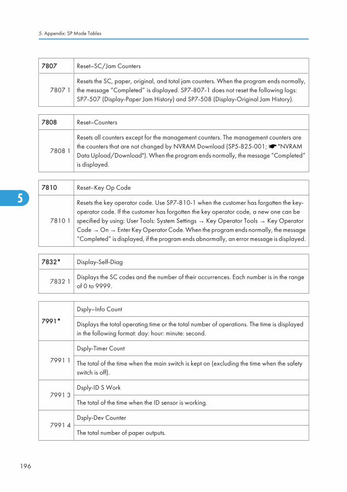
7807 Reset–SC/Jam Counters
7807 1Resets the SC, paper, original, and total jam counters. When the program ends normally,the message “Completed” is displayed. SP7-807-1 does not reset the following logs:SP7-507 (Display-Paper Jam History) and SP7-508 (Display-Original Jam History).
7808 Reset–Counters
7808 1
Resets all counters except for the management counters. The management counters arethe counters that are not changed by NVRAM Download (SP5-825-001; "NVRAMData Upload/Download"). When the program ends normally, the message “Completed”is displayed.
7810 Reset–Key Op Code
7810 1
Resets the key operator code. Use SP7-810-1 when the customer has forgotten the key-operator code. If the customer has forgotten the key operator code, a new one can bespecified by using: User Tools: System Settings → Key Operator Tools → Key OperatorCode → On → Enter Key Operator Code. When the program ends normally, the message“Completed” is displayed, if the program ends abnormally, an error message is displayed.
7832* Display-Self-Diag
7832 1Displays the SC codes and the number of their occurrences. Each number is in the rangeof 0 to 9999.
7991*
Dsply–Info Count
Displays the total operating time or the total number of operations. The time is displayedin the following format: day: hour: minute: second.
7991 1
Dsply-Timer Count
The total of the time when the main switch is kept on (excluding the time when the safetyswitch is off).
7991 3Dsply-ID S Work
The total of the time when the ID sensor is working.
7991 4Dsply-Dev Counter
The total number of paper outputs.
5. Appendix: SP Mode Tables
196
5

7991 5Dsply-ID Er Count
The total number of ID-sensor errors.
7992* Reset-Info Count
7992 1Reset-Timer Count
Clears the timer counter (SP7-991-001).
7992 4Reset-Dev Count
Clears the development counter (SP7-991-004).
7992 5Reset-ID Er Count
Clears the ID sensor error counter (SP7-991-005).
SP8-XXX (History)
8191* T: Total Scan PGS [0 to 9999999 / 0 / 1 sheet/step]
001Displays the total number of scanned originals. Both sides are counted when the front andreverse sides of an original (fed from the DF) are scanned.
8192* C: Total Scan PGS [0 to 9999999 / 0 / 1 sheet/step]
001Displays the total number of scanned originals in copy mode. Both sides are counted whenthe front and reverse sides of an original (fed from the DF) are scanned.
8195* S: Total Scan PGS [0 to 9999999 / 0 / 1 sheet/step]
001Displays the total number of scanned originals in scanner mode. Both sides are countedwhen the front and reverse sides of an original (fed from the DF) are scanned.
8221* ADF Org Feed [0 to 9999999 / 0 / 1 sheet/step]
001Front
Displays the total number of scanned front sides of originals fed from the DF.
System Service Mode (Basic: D067/D072)
197
5

002Back
Displays the total number of scanned 2nd sides of originals fed from the DF.
8381* T: Total Prt PGS [0 to 9999999 / 0 / 1 sheet/step]
001 Displays the print count of all application programs.
8382* C: Total Prt PGS [0 to 9999999 / 0 / 1 sheet/step]
001 Displays the print count of the copier application program.
8384* P: Total Prt PGS [0 to 9999999 / 0 / 1 sheet/step]
001 Displays the print count of the printer application program.
8411* Prints/Duplex [0 to 9999999 / 0 / 1 sheet/step]
001 Displays the total count of the duplex printing.
8422* C: PrtPGS/Dup Comb [0 to 9999999 / 0 / 1 sheet/step]
001 Simplex > Duplex
Displays the total print count of copier applicationclassified by combination/duple type.
002 Duplex> Duplex
004 Simplex Combine
005 Duplex Combine
006 2> (2 in 1)
007 4> (4 in 1)
8441* T: PrtPGS/Ppr Size
[0 to 9999999 / 0 / 1 sheet/step]8442* C: PrtPGS/Ppr Size
8444* S: PrtPGS/Ppr Size
5. Appendix: SP Mode Tables
198
5

-002 A4
Displays the number of pages printed by each copierapplication program.
-003 A5
-005 B5
-007 LG
-008 LT
-009 HLT
-254 Other (Standard)
-255 Other (Custom)
8451* C: PrtPGS/Ppr Tray [0 to 9999999 / 0 / 1 sheet/step]
001 Bypass Tray
Displays the total print count classified by paper source.002 Tray 1
003 Tray 2
004 Tray 3
8461* T: PrtPGS/Ppr Type
[0 to 9999999 / 0 / 1 sheet/step]8462* C: PrtPGS/Ppr Type
8464* S: PrtPGS/Ppr Type
-001 Normal
Displays the total number of pages printed by each copierapplication program.
-004 Thick
-007 OHP
-008 Other
8522* C:PrtPGS/FIN [0 to 9999999/ 0 / 1/step]
001 SortThe SP counts by finishing mode the total number of pagesprinted by the Copy application.
System Service Mode (Basic: D067/D072)
199
5

Input Check (SP5-803)
Conducting Input Check
1. Select SP5-803.
2. Select the number (see the table below) corresponding to the component.
3. Select “Execute.” The copy mode is activated.
4. The sign “01H” or “00H” is displayed (see the table below).
Input Check Table
Num. Sensor/Switch 1h 0h
001 Safety SW Open Closed
003 Right Cover SW Open Closed
006 Upper Relay S Paper detected Not detected
007 Lower Relay S Paper detected Not detected
009 Regist Sensor Paper detected Not detected
010 Exit Sensor Paper detected Not detected
011 Duplex Inverter S Paper detected Not detected
014 By-pass PE S Paper detected Not detected
016 Upper PE S Paper detected Not detected
017 BK-Upper PE S Paper detected Not detected
020 BK-Lower PE S Paper detected Not detected
027 PCU Set Signal Installed Not installed
028 BK type * *
030 Duplex Installed Installed Not installed
032 Main M Lock Locked Not locked
033 Polygon M Lock Locked Not locked
035 Total CO Install Installed Not installed
5. Appendix: SP Mode Tables
200
5

Num. Sensor/Switch 1h 0h
036 Key CO Install Installed Not installed
037 L-Synchronization Detected Not detected
039 DF-Cover Open S Open Closed
040 DF-Original Set S Paper detected Not detected
041 DF-Registration S Paper detected Not detected
042 DF-Exit S Paper detected Not detected
044 DF-Reverse S Paper detected Not detected
045 Platen Cover S Open Closed
050 Fan Motor Lock (High speed) High speed Low speed or stop
052 Front Cover SW Open Closed
053 HP Sensor Detected Not detected
055 BK-UpperCover SW Open Closed
056 BK-LowerCover SW Open Closed
* Available Paper Feed Unit
00 None
30 1-tray paper feed unit
Output Check (SP5-804)
Conducting Output Check
• To prevent mechanical or electrical damage, do not keep an electrical component on for a long time.
1. Select SP5-804.
2. Select the number (see the table below) corresponding to the component.
3. Select “ON.”
4. To stop the operation, select “OFF.”
System Service Mode (Basic: D067/D072)
201
5

Output Check Table
Num. Component
001 Main M- Fwd
002 Main M- Rev
003 Quenching Lamp
004 Toner Sup CL
005 Fan M- High
006 Fan M- Low
007 Registration CL
008 By-pass Feed CL
009 Upper Feed CL
010 BK-Upper Feed CL
015 BK-Lower Feed CL
020 Duplex Inv M- Rev
021 Duplex Inv M- Fwd
024 Duplex Inv M- Hold
026 Polygon M
027 Polygon M/LD
028 LD
029 DF-Feed M
030 DF-Transport M
031 DF-Feed CL
034 DF-Gate SOL (Junction Gate Solenoid)
038 Fusing SOL
When checking Fan Motor High (005) or Fan Motor Low (006) note the following:
5. Appendix: SP Mode Tables
202
5

• These motors may not respond when the fusing temperature is high.
• Selecting “ON” checks that one of these motors normally operates. Selecting “OFF” turns off themotor that you have started by selecting “ON.” However, this does not guarantee that the motornormally stops during normal operation.
Printer Service Program Mode Table
SP No. Description Function and Setting
1003 Clear Setting Not used
1005 Display Version Displays the version of the controller firmware.
1006 Sample/Locked print
0: Link with Doc., 1: On
Enables and disables the document server. When you select “0”the document server is enabled or disables in accordance withcopy service mode SP5-967. When you select “1” the documentserver is enabled regardless of service mode SP5-967.
Scanner Program Mode Table
Service Table Key
Notation What it means
[range / default /step]
Example: [-9 to +9 / +3.0 / 0.1 mm step]. The setting can be adjusted in therange ±9, value reset to +3.0 after an NVRAM reset, and the value can bechanged in 0.1 mm steps with each key press.
italics Comments added for your reference.
*This value is stored in NVRAM. After a RAM reset, the default value (factorysetting) is restored.
DFU Denotes “Design or Factory Use”. Do not change this value.
SP1 Mode Number Function and [Setting]
System Service Mode (Basic: D067/D072)
203
5

1001* 5 Scan NV Version
Displays the scanner NV version.
This shows as following: Function name _ Model name_ Version
1004* 1 Compression Type
Selects the compression type for binary pictureprocessing.
[1: MH, 2: MR, 3: MMR]
1005* 1 Erase Margin
Creates an erase margin for all edges of the scannedimage.
If the machine has scanned the edge of the original,create a margin.
[0 to 5 / 0mm / 1mm step]
1009* 1 Remote Scan disable
Enables or disables the network TWAIN scannerfunction.
0: enable, 1: disable
1012 1 User Info Release
Clears or does not clear a user information after a job.
[0 or 1 / 1 / - ]
0: Not clear, 1: Clear
1013 1 Multi Media Func
Display or not display a “Scan To Multi Media”function.
[0 or 1 / 1 / - ]
0: OFF, 1: ON
SP Number/Name Function and [Setting]
2021
Compression level (grayscale or full color)
These SP codes set the compression ratio for the grayscale or full color processing modethat can be selected with the notch settings on the operation panel.
Range: 5 (lowest ratio) Ö 95 (highest ratio)
001 Comp1: 5-95 (Middle I-Qual) [5 to 95 / 20 /1/step]
002 Comp2: 5-95 (High I-Qual) [5 to 95 / 40 /1/step]
003 Comp3: 5-95 (Low I-Qual) [5 to 95 / 65 /1/step]
004 Comp4: 5-95 (Highest I-Qual) [5 to 95 / 80 /1/step]
5. Appendix: SP Mode Tables
204
5

SP Number/Name Function and [Setting]
005 Comp5: 5-95 (Lowest I-Qual) [5 to 95 / 95 /1/step]
For the settings of the image quality, see the copier SP-mode table.
System Service Mode (Basic: D067/D072)
205
5

5. Appendix: SP Mode Tables
206
5

6. Appendix: Fax TroubleshootingGuide (Only For D068/D069)
Fax Error Codes• This section is used only for F/SPF models (D068/D069).
• If an error code occurs, retry the communication. If the same problem occurs, try to fix the problemas suggested below. Note that some error codes appear only in the error code display and on theservice report.
Code Meaning Suggested Cause/Action
0-00DIS/NSF not detected within40 s of Start being pressed
• Check the line connection.
• The machine at the other end may be incompatible.
• Replace the NCU or FCU.
• Check for DIS/NSF with an oscilloscope.
• If the rx signal is weak, there may be a bad line.
0-01 DCN received unexpectedly• The other party is out of paper or has a jammed printer.
• The other party pressed Stop during communication.
0-03Incompatible modem at theother end
The other terminal is incompatible.
0-04CFR or FTT not received aftermodem training
• Check the line connection.
• Try changing the tx level and/or cable equalizersettings.
• Replace the FCU.
• The other terminal may be faulty; try sending to anothermachine.
• If the rx signal is weak or defective, there may be abad line.
Cross reference
Tx level - NCU Parameter 01 (PSTN)
Cable equalizer - G3 Switch 07 (PSTN)
Dedicated Tx parameters in Service Program Mode
207
6

Code Meaning Suggested Cause/Action
0-05Modem training fails even G3shifts down to 2400 bps.
• Check the line connection.
• Try adjusting the tx level and/or cable equalizer.
• Replace the FCU.
• Check for line problems.
Cross reference
See error code 0-04.
0-06The other terminal did not replyto DCS
• Check the line connection.
• Try adjusting the tx level and/or cable equalizersettings.
• Replace the NCU or FCU.
• The other end may be defective or incompatible; trysending to another machine.
• Check for line problems.
Cross reference
See error code 0-04.
0-07No post-message responsefrom the other end after a pagewas sent
• Check the line connection.
• Replace the NCU or FCU.
• The other end may have jammed or run out of paper.
• The other end user may have disconnected the call.
• Check for a bad line.
• The other end may be defective; try sending to anothermachine.
6. Appendix: Fax Troubleshooting Guide (Only For D068/D069)
208
6

Code Meaning Suggested Cause/Action
0-08The other end sent RTN or PINafter receiving a page, becausethere were too many errors
• Check the line connection.
• Replace the NCU or FCU.
• The other end may have jammed, or run out of paperor memory space.
• Try adjusting the tx level and/or cable equalizersettings.
• The other end may have a defective modem/NCU/FCU; try sending to another machine.
• Check for line problems and noise.
Cross reference
• Tx level - NCU Parameter 01 (PSTN)
• Cable equalizer - G3 Switch 07 (PSTN)
• Dedicated Tx parameters in Service Program Mode
0-14Non-standard post messageresponse code received
• Incompatible or defective remote terminal; try sendingto another machine.
• Noisy line: resend.
• Try adjusting the tx level and/or cable equalizersettings.
• Replace the NCU or FCU.
Cross reference
See error code 0-08.
0-15The other terminal is notcapable of specific functions.
The other terminal is not capable of accepting the followingfunctions, or the other terminal’s memory is full.
• Confidential rx
• Transfer function
• SEP/SUB/PWD/SID
Fax Error Codes
209
6

Code Meaning Suggested Cause/Action
0-16CFR or FTT not detected aftermodem training in confidentialor transfer mode
• Check the line connection.
• Replace the NCU or FCU.
• Try adjusting the tx level and/or cable equalizersettings.
• The other end may have disconnected, or it may bedefective; try calling another machine.
• If the rx signal level is too low, there may be a lineproblem.
Cross reference
See error code 0-08.
0-20Facsimile data not receivedwithin 6 s of retraining
• Check the line connection.
• Replace the NCU or FCU.
• Check for line problems.
• Try calling another fax machine.
• Try adjusting the reconstruction time for the first lineand/or rx cable equalizer setting.
Cross reference
Reconstruction time - G3 Switch 0A, bit 6
Rx cable equalizer - G3 Switch 07 (PSTN)
0-21
EOL signal (end-of-line) fromthe other end not receivedwithin 5 s of the previous EOLsignal
• Check the connections between the FCU, NCU, & line.
• Check for line noise or other line problems.
• Replace the NCU or FCU.
• The remote machine may be defective or may havedisconnected.
Cross reference
Maximum interval between EOLs and between ECM frames- G3 Bit Switch 0A, bit 4
6. Appendix: Fax Troubleshooting Guide (Only For D068/D069)
210
6

Code Meaning Suggested Cause/Action
0-22
The signal from the other endwas interrupted for more thanthe acceptable modem carrierdrop time (default: 200 ms)
• Check the line connection.
• Replace the NCU or FCU.
• Defective remote terminal.
• Check for line noise or other line problems.
• Try adjusting the acceptable modem carrier drop time.
Cross reference
Acceptable modem carrier drop time - G3 Switch 0A, bits0 and 1
0-23Too many errors duringreception
• Check the line connection.
• Replace the NCU or FCU.
• Defective remote terminal.
• Check for line noise or other line problems.
• Try asking the other end to adjust their tx level.
• Try adjusting the rx cable equalizer setting and/or rxerror criteria.
Cross reference
Rx cable equalizer - G3 Switch 07 (PSTN)
Rx error criteria - Communication Switch 02, bits 0 and 1
0-30The other terminal did not replyto NSS(A) in AI short protocolmode
• Check the line connection.
• Try adjusting the tx level and/or cable equalizersettings.
• The other terminal may not be compatible.
Cross reference
Dedicated tx parameters - Section 4
0-32
The other terminal sent a DCS,which contained functions thatthe receiving machine cannothandle.
• Check the protocol dump list.
• Ask the other party to contact the manufacturer.
0-33The data reception (not ECM) isnot completed within 10minutes.
• Check the line connection.
• The other terminal may have a defective modem/NCU/FCU.
Fax Error Codes
211
6

Code Meaning Suggested Cause/Action
0-52Polarity changed duringcommunication
• Check the line connection.Retry communication.
0-55 FCU does not detect the SG3.• FCU firmware or board defective.
• SG3 firmware or board defective.
0-56The stored message dataexceeds the capacity of themailbox in the SG3.
• SG3 firmware or board defective.
0-70
The communication modespecified in CM/JM was notavailable
(V.8 calling and calledterminal)
• The other terminal did not have a compatiblecommunication mode (e.g., the other terminal was aV.34 data modem and not a fax modem.)
• A polling tx file was not ready at the other terminalwhen polling rx was initiated from the calling terminal.
0-74The calling terminal fell back toT.30 mode, because it could notdetect ANSam after sending CI.
• The calling terminal could not detect ANSam due tonoise, etc.
• ANSam was too short to detect.
• Check the line connection and condition.
• Try making a call to another V.8/V.34 fax.
0-75
The called terminal fell back toT.30 mode, because it could notdetect a CM in response toANSam (ANSam timeout).
• The terminal could not detect ANSam.
• Check the line connection and condition.
• Try receiving a call from another V.8/V.34 fax.
0-76
The calling terminal fell back toT.30 mode, because it could notdetect a JM in response to CM
(CM timeout).
• The called terminal could not detect a CM due to noise,etc.
• Check the line connection and condition.
• Try making a call to another V.8/V.34 fax.
0-77
The called terminal fell back toT.30 mode, because it could notdetect a CJ in response to JM
(JM timeout).
• The calling terminal could not detect a JM due to noise,etc.
• A network that has narrow bandwidth cannot pass JMto the other end.
• Check the line connection and condition.
• Try receiving a call from another V.8/V.34 fax.
6. Appendix: Fax Troubleshooting Guide (Only For D068/D069)
212
6

Code Meaning Suggested Cause/Action
0-79The called terminal detected CIwhile waiting for a V.21 signal.
• Check for line noise or other line problems.
• If this error occurs, the called terminal falls back to T.30 mode.
0-80The line was disconnected dueto a timeout in V.34 phase 2 –line probing.
• The guard timer expired while starting these phases.Serious noise, narrow bandwidth, or low signal levelcan cause these errors.
If these errors happen at the transmitting terminal:
• Try making a call at a later time.
• Try using V.17 or a slower modem using dedicated txparameters.
• Try increasing the tx level.
• Try adjusting the tx cable equalizer setting.
If these errors happen at the receiving terminal:
• Try adjusting the rx cable equalizer setting.
• Try increasing the tx level.
• Try using V.17 or a slower modem if the same error isfrequent when receiving from multiple senders.
0-81The line was disconnected dueto a timeout in V.34 phase 3 –equalizer training.
0-82The line was disconnected dueto a timeout in the V.34 phase 4– control channel start-up.
0-83The line was disconnected dueto a timeout in the V.34 controlchannel restart sequence.
0-84
The line was disconnected dueto abnormal signaling in V.34phase 4 – control channel start-up.
• The signal did not stop within 10 s.
• Turn off the machine, then turn it back on.
• If the same error is frequent, replace the FCU.
0-85The line was disconnected dueto abnormal signaling in V.34control channel restart.
• The signal did not stop within 10 s.
• Turn off the machine, then turn it back on.
• If the same error is frequent, replace the FCU.
0-86
The line was disconnectedbecause the other terminalrequested a data rate usingMPh that was not available inthe currently selected symbolrate.
• The other terminal was incompatible.
• Ask the other party to contact the manufacturer.
Fax Error Codes
213
6

Code Meaning Suggested Cause/Action
0-87The control channel started afteran unsuccessful primarychannel.
• The receiving terminal restarted the control channelbecause data reception in the primary channel wasnot successful.
• This does not result in an error communication.
0-88
The line was disconnectedbecause PPR was transmitted/received 9 (default) times withinthe same ECM frame.
• Try using a lower data rate at the start.
• Try adjusting the cable equalizer setting.
2-11Only one V.21 connection flagwas received
• Replace the FCU.
2-12 Modem clock irregularity • Replace the FCU.
2-13 Modem initialization error
• Turn off the machine, then turn it back on.
• Update the modem ROM.
• Replace the FCU.
2-23JBIG compression orreconstruction error
• Turn off the machine, then turn it back on.
2-24 JBIG ASIC error • Turn off the machine, then turn it back on.
2-25JBIG data reconstruction error(BIH error)
• JBIG data error
• Check the sender’s JBIG function.
• Update the MBU ROM.
2-26JBIG data reconstruction error(Float marker error)
2-27JBIG data reconstruction error(End marker error)
2-28JBIG data reconstruction error(Timeout)
2-29 JBIG trailing edge maker error• FCU defective
• Check the destination device.
2-50The machine resets itself for afatal FCU system error
• If this is frequent, update the ROM, or replace the FCU.
6. Appendix: Fax Troubleshooting Guide (Only For D068/D069)
214
6

Code Meaning Suggested Cause/Action
2-51The machine resets itselfbecause of a fatalcommunication error
• If this is frequent, update the ROM, or replace the FCU.
2-53Snd msg() in the manual task isan error because the mailboxfor the operation task is full.
• The user did the same operation many times, and thisgave too much load to the machine.
4-01 Line current was cut
• Check the line connector.
• Check for line problems.
• Replace the FCU or the NCU.
4-10
Communication failed becauseof an ID Code mismatch(Closed Network) or Tel. No./CSI mismatch (Protectionagainst Wrong Connections)
• Get the ID Codes the same and/or the CSIsprogrammed correctly, then resend.
• The machine at the other end may be defective.
5-10 DCR timer expired • Replace the FCU.
5-20Storage impossible because ofa lack of memory • Temporary memory shortage.
• Test the SAF memory.5-21 Memory overflow
5-23Print data error when printing asubstitute rx or confidential rxmessage
• Test the SAF memory.
• Ask the other end to resend the message.
5-25 SAF file access error• Replace an SD card or HDD.
• Replace the FCU.
6-00G3 ECM - T1 time out duringreception of facsimile data
• Try adjusting the rx cable equalizer.
• Replace the FCU.6-01G3 ECM - no V.21 signal wasreceived
6-02 G3 ECM - EOR was received
6-04 G3 ECM - RTC not detected
• Check the line connection.
• Check for a bad line or defective remote terminal.
• Replace the FCU.
Fax Error Codes
215
6

Code Meaning Suggested Cause/Action
6-05G3 ECM - facsimile data framenot received within 18 s of CFR,but there was no line fail
• Check the line connection.
• Check for a bad line or defective remote terminal.
• Replace the FCU.
• Try adjusting the rx cable equalizer
Cross reference
• Rx cable equalizer - G3 Switch 07 (PSTN)
6-06G3 ECM - coding/decodingerror
• Defective FCU.
• The other terminal may be defective.
6-08G3 ECM - PIP/PIN received inreply to PPS.NULL
• The other end pressed Stop during communication.
• The other terminal may be defective.
6-09 G3 ECM - ERR received
• Check for a noisy line.
• Adjust the tx levels of the communicating machines.
• See code 6-05.
6-10
G3 ECM - error frames stillreceived at the other end afterall communication attempts at2400 bps
• Check for line noise.
• Adjust the tx level (use NCU parameter 01 or thededicated tx parameter for that address).
• Check the line connection.
• Defective remote terminal.
6-21V.21 flag detected during highspeed modem communication
• The other terminal may be defective or incompatible.
6-22
The machine resets thesequence because of anabnormal handshake in the V.34 control channel
• Check for line noise.
• If the same error occurs frequently, replace the FCU.
• Defective remote terminal.
6-99V.21 signal not stopped within6 s
• Replace the FCU.
13-17 SIP user name registration error
• Double registration of the SIP user name.
• Capacity for user-name registration in the SIP server isnot sufficient.
6. Appendix: Fax Troubleshooting Guide (Only For D068/D069)
216
6

Code Meaning Suggested Cause/Action
13-18 SIP server access error• Incorrect initial setting for the SIP server.
• Defective SIP server.
13-24SIP authentication passworderror
• The input password for the authentication does notmatch the password registered in the SIP server.
14-00 SMTP Send Error
• Error occurred during sending to the SMTP server.Occurs for any error other than 14-01 to 16. Forexample, the mail address of the system administratoris not registered.
14-01 SMTP Connection Failed
• Failed to connect to the SMTP server (timeout) becausethe server could not be found.
• The PC is not ready to transfer files.
• SMTP server not functioning correctly.
• The DNS IP address is not registered.
• Network not operating correctly.
• Destination folder selection not correct.
14-02No Service by SMTP Service(421)
• SMTP server operating incorrectly, or the destinationfor direct SMTP sending is not correct.
• Contact the system administrator and check that theSMTP server has the correct settings and operatescorrectly.
• Contact the system administrator for direct SMTPsending and check the sending destination.
Fax Error Codes
217
6

Code Meaning Suggested Cause/Action
14-03Access to SMTP Server Denied(450)
• Failed to access the SMTP server because the accessis denied.
• SMTP server operating incorrectly. Contact the systemadministrator to determine if there is a problem with theSMTP server and to check that the SMTP server settingsare correct.
• Folder send destination is incorrect. Contact the systemadministrator to determine that the SMTP serversettings and path to the server are correct.
• Device settings incorrect. Confirm that the user nameand password settings are correct.
• Direct SMTP destination incorrect. Contact the systemadministrator to determine if there is a problem at thedestination at that the settings at the destination arecorrect.
14-04Access to SMTP Server Denied(550)
• SMTP server operating incorrectly
• Direct SMTP sending not operating correctly
14-05 SMTP Server HDD Full (452)
• Failed to access the SMTP server because the HDD onthe server is full.
• Insufficient free space on the HDD of the SMTP server.Contact the system administrator and check theamount of space remaining on the SMTP server HDD.
• Insufficient free space on the HDD where thedestination folder is located. Contact the systemadministrator and check the amount of spaceremaining on the HDD where the target folder islocated.
• Insufficient free space on the HDD at the targetdestination for SMTP direct sending. Contact thesystem administrator and check the amount of spaceremaining on the target HDD.
14-06User Not Found on SMTPServer (551)
• The designated user does not exist.
• The designated user does not exist on the SMTP server.
• The designated address is not for use with direct SMTPsending.
6. Appendix: Fax Troubleshooting Guide (Only For D068/D069)
218
6

Code Meaning Suggested Cause/Action
14-07Data Send to SMTP ServerFailed (4XX)
• Failed to access the SMTP server because thetransmission failed.
• PC not operating correctly.
• SMTP server operating incorrectly
• Network not operating correctly.
• Destination folder setting incorrect.
• Direct SMTP sending not operating correctly.
14-08Data Send to SMTP ServerFailed (5XX)
• Failed to access the SMTP server because thetransmission failed.
• SMTP server operating incorrectly
• Destination folder setting incorrect.
• Direct SMTP sending not operating correctly.
• Software application error.
14-09Authorization Failed forSending to SMTP Server
• POP-Before-SMTP or SMTP authorization failed.
• Incorrect setting for file transfer
14-10 Addresses Exceeded• Number of broadcast addresses exceeded the limit for
the SMTP server.
14-11 Buffer Full
• The send buffer is full so the transmission could not becompleted. Buffer is full due to using Scan-to-Emailwhile the buffer is being used send mail at the sametime.
14-12 Data Size Too Large• Transmission was cancelled because the detected size
of the file was too large.
14-13 Send Cancelled• Processing is interrupted because the user pressed
Stop.
14-14 Security Locked File Error• Update the software because of the defective
software.
14-15 Mail Data Error
• The transmitting a mail is interrupted via DCS due tothe incorrect data.
• Update the software because of the defectivesoftware.
Fax Error Codes
219
6

Code Meaning Suggested Cause/Action
14-16Maximum Division NumberError
• When a mail is divided for the mail transmission andthe division number of a mail are more than thespecified number, the mail transmission is interrupted.
• Update the software because of the defectivesoftware.
14-17 Incorrect Ticket• Update the software because of the defective
software.
14-18 Access to MCS File Error
• The access to MCS file is denied due to the nopermission of access.
• Update the software because of the defectivesoftware.
14-30 MCS File Creation Failed
Failed to create the MCS file because:
• The number of files created with other applications onthe Document Server has exceeded the limit.
• HDD is full or not operating correctly.
• Software error.
14-31 UFS File Creation Failed
UFS file could not be created:
• Not enough space in UFS area to handle both Scan-to-Email and IFAX transmission.
• HDD full or not operating correctly.
• Software error.
14-32Cancelled the Mail Due to ErrorDetected by NFAX
• Error detected with NFAX and send was cancelled dueto a software error.
14-33No Mail Address For theMachine
• Neither the mail address of the machine nor the mailaddress of the network administrator is registered.
14-34Address designated in thedomain for SMTP sending doesnot exist
• Operational error in normal mail sending or directSMTP sending.
• Check the address selected in the address book forSMTP sending.
• Check the domain selection.
6. Appendix: Fax Troubleshooting Guide (Only For D068/D069)
220
6

Code Meaning Suggested Cause/Action
14-50 Mail Job Task Error
Due to an FCU mail job task error, the send was cancelled:
• Address book was being edited during creation of thenotification mail.
• Software error.
14-51UCS Destination DownloadError
Not even one return notification can be downloaded:
• The address book was being edited.
• The number for the specified destination does not exist(it was deleted or edited after the job was created).
14-60 Send Cancel Failed• The cancel operation by the user failed to cancel the
send operation.
14-61Notification Mail Send Failedfor All Destinations
• All addresses for return notification mail failed.
14-62Transmission Error due to theexistence of zero line page
• When the 0 line page exists in received pages with G3communication, the transmission is interrupted.
15-01POP3/IMAP4 Server NotRegistered
• At startup, the system detected that the IP address ofthe POP3/IMAP4 server has not been registered inthe machine.
15-02POP3/IMAP4 Mail AccountInformation Not Registered
• The POP3/IMAP4 mail account has not beenregistered.
15-03 Mail Address Not Registered • The mail address has not been registered.
15-10 DCS Mail Receive Error • Error other than 15-11 to 15-18.
15-11 Connection Error
The DNS or POP3/IMAP4 server could not be found:
• The IP address for DNS or POP3/IMAP4 server is notstored in the machine.
• The DNS IP address is not registered.
• Network not operating correctly.
15-12 Authorization Error
POP3/IMAP4 send authorization failed:
• Incorrect IFAX user name or password.
• Access was attempted by another device, such as thePC.
• POP3/IMAP4 settings incorrect.
Fax Error Codes
221
6

Code Meaning Suggested Cause/Action
15-13 Receive Buffer Full• Occurs only during manual reception. Transmission
cannot be received due to insufficient buffer space. Thebuffer is being used for mail send or Scan-to-Email.
15-14 Mail Header Format Error• The mail header is not standard format. For example,
the Date line description is incorrect.
15-15 Mail Divide Error• The e-mail is not in standard format. There is no
boundary between parts of the e-mail, including theheader.
15-16 Mail Size Receive Error • The mail cannot be received because it is too large.
15-17 Receive Timeout• May occur during manual receiving only because the
network is not operating correctly.
15-18 Incomplete Mail Received • Only one portion of the mail was received.
15-31Final Destination for TransferRequest Reception Format Error
• The format of the final destination for the transferrequest was incorrect.
15-39Send/Delivery DestinationError
The transmission cannot be delivered to the final destination:
• Destination file format is incorrect.
• Could not create the destination for the filetransmission.
15-41 SMTP Receive Error• Reception rejected because the transaction exceeded
the limit for the “Auth. E-mail RX” setting.
15-42 Off Ramp Gateway Error• The delivery destination address was specified with
Off Ramp Gateway OFF.
15-43 Address Format Error • Format error in the address of the Off Ramp Gateway.
15-44 Addresses Over• The number of addresses for the Off Ramp Gateway
exceeded the limit of 30.
15-61 Attachment File Format Error • The attached file is not TIFF format.
6. Appendix: Fax Troubleshooting Guide (Only For D068/D069)
222
6

Code Meaning Suggested Cause/Action
15-62 TIFF File Compatibility Error
Could not receive transmission due to:
• Resolution error
• Image of resolution greater than 200 dpi withoutextended memory.
• Resolution is not supported.
• Page size error
• The page size was larger than A3.
• Compression error
• File was compressed with other than MH, MR, orMMR.
15-63 TIFF Parameter Error
The TIFF file sent as the attachment could not be receivedbecause the TIFF header is incorrect:
• The TIFF file attachment is a type not supported.
• The TIFF file attachment is corrupted.
• Software error.
15-64 TIFF Decompression Error
The file received as an attachment caused the TIFFdecompression error:
• The TIFF format of the attachment is corrupted.
• Software error.
15-71 Not Binary Image Data• The file could not be received because the attachment
was not binary image data.
15-73 MDN Status Error• Could not find the Disposition line in the header of the
Return Receipt, or there is a problem with the firmware.
15-74 MDN Message ID Error• Could not find the Original Message ID line in the
header of the Return Receipt, or there is a problem withthe firmware.
15-80 Mail Job Task Read Error
• Could not receive the transmission because thedestination buffer is full and the destination could notbe created (this error may occur when receiving atransfer request or a request for notification ofreception).
Fax Error Codes
223
6

Code Meaning Suggested Cause/Action
15-81Repeated DestinationRegistration Error
• Could not repeat receive the transmission because thedestination buffer is full and the destination could notbe created (this error may occur when receiving atransfer request or a request for notification ofreception).
15-91 Send Registration Error
Could not receive the file for transfer to the final destination:
• The format of the final destination or the transferdestination is incorrect.
• Destinations are full so the final and transferdestinations could not be created.
15-92 Memory Overflow• Transmission could not be received because memory
overflowed during the transaction.
15-93 Memory Access Error• Transaction could not complete due to a malfunction
of SAF memory.
15-94 Incorrect ID Code• The machine rejected an incoming e-mail for transfer
request, because the ID code in the incoming e-maildid not match the ID code registered in the machine.
15-95 Transfer Station Function• The machine rejected an incoming e-mail for transfer
because the transfer function was unavailable.
22-00Original length exceeded themaximum scan length
• Divide the original into more than one page.
• Check the resolution used for scanning. Lower the scanresolution if possible.
• Add optional page memory.
22-01Memory overflow whilereceiving
• Wait for the files in the queue to be sent.
• Delete unnecessary files from memory.
• Transfer the substitute reception files to an another faxmachine, if the machine’s printer is busy or out of order.
• Add an optional SAF memory card or hard disk.
22-02Tx or rx job stalled due to linedisconnection at the other end
• The job started normally but did not finish normally;data may or may not have been received fully.
• Restart the machine.
6. Appendix: Fax Troubleshooting Guide (Only For D068/D069)
224
6

Code Meaning Suggested Cause/Action
22-04The machine cannot storereceived data in the SAF
• Update the ROM
• Replace the FCU.
22-05No G3 parameter confirmationanswer
• Defective FCU board or firmware.
23-00Data read timeout duringconstruction
• Restart the machine.
• Replace the FCU.
25-00The machine software resetsitself after a fatal transmissionerror occurred
• Update the ROM
• Replace the FCU.
F0-xx V.34 modem error • Replace the FCU.
F6-xx SG3 modem error
• Update the SG3 modem ROM.
• Replace the SG3 board.
• Check for line noise or other line problems.
• Try communicating another V.8/V.34 fax.
Fax Error Codes
225
6

IFAX Troubleshooting• This section is used only for F/SPF models (D068/D069).
• Use the following procedures to determine whether the machine or another part of the network iscausing the problem.
Communication Route Item Action [Remarks]
General LAN
1. Connection with theLAN
• Check that the LAN cable is connected to themachine.
• Check that the LEDs on the hub are lit.
2. LAN activity• Check that other devices connected to the LAN
can communicate through the LAN.
Between IFAX and PC
1. Network settings onthe PC
• Check the network settings on the PC.
[Is the IP address registered in the TCP/IP propertiesin the network setup correct?
• Check the IP address with the administrator ofthe network.]
2. Check that PC canconnect with themachine
• Use the “ping” command on the PC to contactthe machine.
[At the MS-DOS prompt, type ping then the IP addressof the machine, then press Enter.]
3. LAN settings in themachine
• Check the LAN parameters
• Check if there is an IP address conflict with otherPCs.
[Use the “Network” function in the User Tools.
If there is an IP address conflict, inform theadministrator.]
Between machine ande-mail server
LAN settings in themachine
• Check the LAN parameters
• Check if there is an IP address conflict with otherPCs.
[Use the “Network” function in the User Tools.
If there is an IP address conflict, inform theadministrator.]
6. Appendix: Fax Troubleshooting Guide (Only For D068/D069)
226
6

Communication Route Item Action [Remarks]
Between machine ande-mail server
1. E-mail account onthe server
• Make sure that the machine can log into the e-mail server.
• Check that the account and password stored inthe server are the same as in the machine.
[Ask the administrator to check.]
2. E-mail server
• Make sure that the client devices which have anaccount in the server can send/receive e-mail.
[Ask the administrator to check.
Send a test e-mail with the machine’s own number asthe destination. The machine receives the returned e-mail if the communication is performed successfully.]
Between e-mail serverand internet
1. E-mail account onthe Server
• Make sure that the PC can log into the e-mailserver.
• Check that the account and password stored inthe server are the same as in the machine.
[Ask the administrator to check.]
2. E-mail server
• Make sure that the client devices which have anaccount in the server can send/receive e-mail.
[Ask the administrator to check.
Send a test e-mail with the machine’s own number asthe destination. The machine receives the returned e-mail if the communication is performed successfully.]
3. Destination e-mailaddress
• Make sure that the e-mail address is actuallyused.
• Check that the e-mail address contains noincorrect characters such as spaces.
Between e-mail serverand internet
Router settings
• Use the “ping” command to contact the router.
• Check that other devices connected to the routercan sent data over the router.
[Ask the administrator of the server to check.]
IFAX Troubleshooting
227
6

Communication Route Item Action [Remarks]
Between e-mail serverand internet
Error message by e-mail from the network ofthe destination.
• Check whether e-mail can be sent to anotheraddress on the same network, using theapplication e-mail software.
• Check the error e-mail message.
[Inform the administrator of the LAN.]
6. Appendix: Fax Troubleshooting Guide (Only For D068/D069)
228
6

IP-Fax TroubleshootingThis section is used only for F/SPF models (D068/D069).
IP-Fax Transmission
Cannot send by IP Address/Host Name
Check Point Action
1 LAN cable connected? Check the LAN cable connection.
2 Specified IP address/host name correct? Check the IP address/host name.
3 Firewall/NAT is installed?Cannot breach the firewall. Send by usinganother method (Fax, Internet Fax)
4 Transmission sent manually? Manual sending not supported.
5 IP address of local machine registered? Register the IP address.
6Remote terminal port number setting other than1720?
Send by specifying the port number.
7 Specified port number correct? Confirm the port number of the remote fax.
8 DNS server registered when host name specified? Contact the network administrator.
9 Remote fax a T.38 terminal?Check whether the remote fax is a T38terminal.
10 Remote fax switched off or busy? Check that the remote fax is switched on.
11 Network bandwidth too narrow?
Request the network administrator to increasethe bandwidth.
Raise the delay level.
IPFAX SW 01 Bit 0 to 3
IP-Fax bandwidth is the same as the DCSspeed. Set IP-Fax SW00 Bit 6 to 1.
12 Remote fax cancelled transmission?Check whether the remote fax cancelled thetransmission.
IP-Fax Troubleshooting
229
6

Cannot send via VoIP Gateway
Check Point Action
1 LAN cable connected? Check the LAN cable connection.
2 VoIP Gateway T.38 standard? Contact the network administrator.
3 VoIP Gateway installed correctly? Contact the network administrator.
4 VoIP Gateway power switched on? Contact the network administrator.
5Is the IP address/host name of the specifiedGateway correct?
Check the IP address/host name.
6 Number of the specified fax correct? Check the remote fax number.
7 Firewall/NAT is installed?Cannot breach the firewall. Send by usinganother method (Fax, Internet Fax)
8 Transmission sent manually? Manual sending not supported.
9 IP address of local fax registered? Register the IP address.
10 DNS registered when host name specified? Contact the network administrator.
11 Remote fax a G3 fax? Check that the remote fax is a G3 fax.
12 G3 fax is connected to VoIP gateway? Check that G3 fax is connected.
13 Remote G3 fax turned on? Check that G3 fax is switched on.
14 Network bandwidth too narrow?
Request the network administrator to increasethe bandwidth.
Raise the network delay level.
IPFAX SW 01 Bit 0 to 3
IP-Fax bandwidth is the same as the DCSspeed. Set IP-Fax SW00 Bit 6 to 1.
Cannot send by Alias Fax number.
Check Point Action
1 LAN cable connected? Check the LAN cable connection.
6. Appendix: Fax Troubleshooting Guide (Only For D068/D069)
230
6

2 Number of specified Alias fax correct?Confirm the Alias of the remote fax.
Error Code: 13-14
3 Firewall/NAT installed?Cannot breach the firewall. Send by usinganother method (Fax, Internet Fax)
4 Transmission sent manually? Manual sending not supported.
5 Gatekeeper installed correctly? Contact the network administrator.
6 Gatekeeper power switched on? Contact the network administrator.
7 IP address/host name of Gatekeeper correct? Check the IP address/host name.
8DNS server registered when Gatekeeper hostname specified?
Contact the network administrator.
9 Enable H.323 SW is set to on?Check the settings.
See User Parameter SW 34 Bit 0
10 IP address of local fax registered? Register the IP address of the local fax.
11 Alias number of local fax registered? Register the Alias number of the local fax.
12 Remote fax registered in Gatekeeper? Contact the network administrator.
13 Remote fax a T.38 terminal?Check whether the remote fax is a T38terminal.
14 Remote fax switched off or busy? Contact the network administrator.
15 Network bandwidth too narrow?
Request the system administrator to increasethe bandwidth.
Raise the delay level.
IPFAX SW 01 Bit 0 to 3
Lower the modem transmission baud rate.
IPFAX SW 05
16 Remote fax cancelled transmission?Check whether the remote fax cancelled thetransmission.
IP-Fax Troubleshooting
231
6

IP-Fax Reception
Cannot receive by IP Address/Host name.
Check Point Action
1 LAN cable connected? Check the LAN cable connection.
2 Firewall/NAT is installed?Cannot breach the firewall. Send by using anothermethod (Fax, Internet Fax)
3 IP address of local fax registered? Register the IP address.
4Port number specified at remote sender fax (ifrequired)?
Request the sender to specify the port number.
5 Specified port number correct (if required)? Request the sender to check the port number.
6DNS server registered when host namespecified on sender side?
Contact the network administrator.
• The sender machine displays this error codeif the sender fax is a Ricoh model.
7 Network bandwidth too narrow?
Request the system administrator to increase thebandwidth.
Lower the start modem reception baud rate on thereceiving side.
IPFAX SW06
8 Remote fax cancelled transmission?Check whether the remote fax cancelled thetransmission.
Cannot receive by VoIP Gateway.
Check Point Action
1 LAN cable connected? Check the LAN cable connection.
2 Firewall/NAT is installed?Cannot breach the firewall. Request the remotefax to send by using another method (Fax, InternetFax)
6. Appendix: Fax Troubleshooting Guide (Only For D068/D069)
232
6

3 VoIP Gateway installed correctly? Contact the network administrator.
4 VoIP Gateway power switched on? Contact the network administrator.
5IP address/host name of specified VoIPGateway correct on sender’s side?
Request the remote fax to check the IP address/host name.
6DNS server registered when host namespecified on sender side?
Contact the network administrator.
7 Network bandwidth too narrow?Request the network administrator to increase thebandwidth.
8 G3 fax connected? Check that G3 fax is connected.
9 G3 fax power switched on? Check that G3 fax is switched on.
Cannot receive by Alias Fax number.
Check Point Action
1 LAN cable connected? Check the LAN cable connection.
2 Firewall/NAT is installed?Cannot the breach firewall. Request the remote faxto send by using another method (Fax, Internet Fax)
3 Gatekeeper installed correctly?
Contact the network administrator.
• The sender machine displays this error codewhen the sender fax is a Ricoh model.
4 Power to Gatekeeper switched on?
Contact the network administrator.
• The sender machine displays this error codewhen the sender fax is a Ricoh model.
5IP address/host name of Gatekeeper correcton the sender’s side?
Request the sender to check the IP address/hostname.
• The sender machine displays this error codewhen the sender fax is a Ricoh model.
IP-Fax Troubleshooting
233
6

6DNS server registered when Gatekeeper hostname specified on sender’s side?
Contact the network administrator.
• The sender machine displays this error codewhen the sender fax is a Ricoh model.
7 Enable H.323 SW is set to on?
Request the sender to check the settings.
User Parameter SW 34 Bit 0
• Only if the remote sender fax is a Ricoh fax.
8 Local fax IP address registered? Register the IP address.
9 Local fax Alias number registered? Register the Alias number.
10 Network bandwidth too narrow?
Request the system administrator to increase thebandwidth.
Lower the start modem reception baud rate on thereceiving side.
IPFAX SW06
11 Remote fax cancelled transmission?Check whether the remote fax cancelled thetransmission.
12 Local fax registered in Gatekeeper?
Contact the network administrator.
• The sender machine displays this error codewhen the sender fax is a Ricoh model.
6. Appendix: Fax Troubleshooting Guide (Only For D068/D069)
234
6

7. Appendix: Fax Service Program(Only For D068/D069)
System Service ModeOnly for F/SPF models: D068/D069
SP1-XXX (Bit Switches)
"Bit Switches"
1 Mode No. Function
101
System Switch
001 – 032 00 – 1FChange the bit switches for system settings for the fax option
( "Bit Switches")
102
Ifax Switch
001 – 016 00 – 0F
Change the bit switches for internet fax settings for the faxoption
( "Bit Switches")
103
Printer Switch
001 – 016 00 – 0FChange the bit switches for printer settings for the fax option( "Bit Switches")
104
Communication Switch
001 – 032 00 – 1F
Change the bit switches for communication settings for the faxoption
( "Bit Switches")
105
G3-1 Switch
001 – 016 00 – 0F
Change the bit switches for the protocol settings of the standardG3 board
( "Bit Switches")
235
7

111
IP fax Switch
001 – 016 00 – 0FChange the bit switches for optional IP fax parameters
( "Bit Switches")
SP2-XXX (RAM Data)
2 Mode No. Function
101
RAM Read/Write
001Change RAM data for the fax board directly. ("Service RAM Addresses")
102
Memory Dump
001 G3-1 Memory DumpPrint out RAM data for the fax board.
( "Service RAM Addresses")
103
G3-1 NCU Parameters
001 – 023 CC, 01 – 22NCU parameter settings for the standard G3 board.( "NCU Parameters")
SP3-XXX (Tel Line Settings)
3 Mode No. Function
101Service Station
001 Fax Number Enter the fax number of the service station.
102Serial Number
000 Enter the fax unit’s serial number.
7. Appendix: Fax Service Program (Only For D068/D069)
236
7

103
PSTN-1 Port Settings
001 Select LineSelect the line type setting for the G3-1 line. If themachine is installed on a PABX line, select “PABX”,“PABX(GND)” or “PABX(FLASH)”.
002PSTN AccessNumber
Enter the PSTN access number for the
G3-1 line.
003Memory LockDisabled
If the customer does not want to receive transmissionsusing Memory Lock on this line, turn this SP on.
107
IPFAX Port Settings
001 H323 Port -
002 SIP Port -
003 RAS Port -
004 Gatekeeper port -
005 T.38 Port -
006 SIP Server Port -
007IPFAX ProtocolPriority
Select "H323" or "SIP".
201FAX SW
001 – 032 00 – 1F -
SP4-XXX (ROM Versions)
4 Mode No. Function
101 002 – 007 FCU ROM Version Displays the FCU ROM version.
102 002 – 065 Error Codes Displays the latest 64 fax error codes.
103 002 – 004 G3-1 ROM Version Displays the G3-1 modem version.
System Service Mode
237
7

SP5-XXX (Initializing)
5 Mode No. Function
101
Initialize SRAM
001Initializes the bit switches and user parameters, user data in the SRAM,files in the SAF memory, and clock.
102Erase All Files
001 Erases all files stored in the SAF memory.
103Reset Bit Switches
001 Resets the bit switches and user parameters.
104
Factory setting
001Resets the bit switches and user parameters, user data in the SRAM andfiles in the SAF memory.
105Reset All Bit Switches
001 Initializes all the current bit switch settings.
106
Reset Security Bit Switches
001Initializes only the security bit switches. If you select automatic output/display for the user parameter switches, the security settings areinitialized.
SP6-XXX (Reports)
6 Mode No. Function
101
System Parameter List
001 -Touch the “ON” button to print the system parameterlist.
102
Service Monitor
001 -Touch the “ON” button to print the service monitorreport.
7. Appendix: Fax Service Program (Only For D068/D069)
238
7

103
G3 Protocol Dump List
001G3-1 (AllCommunications)
Prints the protocol dump list of all communications forthe G3-1 line.
002G3-1
(1 Communication)
Prints the protocol dump list of the last communicationfor the G3-1 line.
105
All Files print out
001 -
Prints out all the user files in the SAF memory, includingconfidential messages.
• Do not use this function, unless the customer ishaving trouble printing confidential messages orrecovering files stored using the memory lockfeature.
106
Journal Print out
001 All JournalsThe machine prints all the communication records onthe report.
002 Specified DateThe machine prints all communication records after thespecified date.
System Service Mode
239
7

107
Log List Print out
001 All log files
These log print out functions are for designer use only.
002 Printer
003 SC/TRAP Stored
004 Decompression
005 Scanner
006 JOB/SAF
007 Reconstruction
008 JBIG
009 G3CCU
010 Fax Job
011 CCU
012 Scanner Condition
108
IP Protocol Dump List
001 All CommunicationsPrints the protocol dump list of all communications forthe IP fax line.
002 1 CommunicationPrints the protocol dump list of the last communicationfor the IP fax line.
SP7-XXX (Test Modes)
These are the test modes for PTT approval.
7 Function
101 G3-1 Modem Tests
102 G3-1 DTMF Tests
103 Ringer Test
104 G3-1 V34 (S2400baud)
7. Appendix: Fax Service Program (Only For D068/D069)
240
7

105 G3-1 V34 (S2800baud)
106 G3-1 V34 (S3000baud)
107 G3-1 V34 (S3200baud)
108 G3-1 V34 (S3429baud)
109 Message Test
System Service Mode
241
7

Bit SwitchesThis section is used only for F/SPF models (D068/D069).
• Do not adjust a bit switch or use a setting that is described as “Not used”, as this may cause themachine to malfunction or to operate in a manner that is not accepted by local regulations. Such bitsare for use only in other areas, such as Japan.
• Default settings for bit switches are not listed in this manual. Refer to the System Parameter List printedby the machine.
System Switches
System Switch 00 [SP No. 1-101-001]
No FUNCTION COMMENTS
0
Dedicated transmission parameterprogramming
0: Disabled, 1: Enabled
Set this bit to 1 before changing any dedicated transmissionparameters.
Reset this bit to 0 after programming dedicated transmissionparameters.
1 Not used Do not change
7. Appendix: Fax Service Program (Only For D068/D069)
242
7

2
Technical data printout on theJournal
0: Disabled
1: Enabled
1: Instead of the personal name, the following data arelisted on the Journal for each G3 communication.
e.g. 0000 (1) // 32 (2) V34 (3) // 288 (4) // 264 (5) // L0100 (6) 03 (7) 04 (8)
(1): EQM value (Line quality data). A larger number means more errors.
(2): Symbol rate (V.34 only)
(3): Final modem type used
(4): Starting data rate (for example, 288 means 28.8 kbps)
(5): Final data rate
(6): Rx revel (refer to the note after this table for how to read the rx level)
(7): Total number of error lines that occurred during non-ECM reception.
(8): Total number of burst error lines that occurred during non-ECM reception.
• EQM and rx level are fixed at “FFFF” in tx mode.
• The seventh and eighth numbers are fixed at “00” for transmission records and ECMreception records.
Rx level calculation
Example: 0000 // 32 V34 // 288/264 // L 01 00 03 04
The four-digit hexadecimal value (N) after “L” indicates the rx level.
The high byte is given first, followed by the low byte. Divide the decimal value of N by -16 to getthe rx level.
In the above example, the decimal value of N (= 0100 [H]) is 256.
So, the actual rx level is 256/-16 = -16 dB
3 Not used Do not change this setting.
4Line error mark print
0: OFF, 1: ON (print)
When "1" is selected, a line error mark is printed on theprintout if a line error occurs during reception.
5
G3/G4 communication parameterdisplay
0: Disabled
1: Enabled
This is a fault-finding aid. The LCD shows the key parameters(see below). This is normally disabled because it cancelsthe CSI display for the user.
Be sure to reset this bit to 0 after testing.
Bit Switches
243
7

6
Protocol dump list output after eachcommunication
0: Off
1: On
This is only used for communication troubleshooting. Itshows the content of the transmitted facsimile protocolsignals. Always reset this bit to 0 after finishing testing.
If system switch 09 bit 6 is at “1”, the list is only printed ifthere was an error during the communication.
7 Not used Do not change the setting.
System Switch 01 - Not used (Do not change the factory settings.)
System Switch 02 [SP No. 1-101-003]
No FUNCTION COMMENTS
0-1 Not used Do not change these settings.
2
Force after transmission stall
0: Off
1: On
With this setting on, the machine resets itself automaticallyif a transmission stalls and fails to complete the job.
3-5 Not used Do not change these settings.
6-7
Memory read/write by RDS
Bit 7: 0, Bit 6: 0
Always disabled
Bit 7: 0, Bit 6: 1
User selectable
Bit 7: 1, Bit 6: 0
User selectable
Bit 7: 1, Bit 6: 1
Always enabled
(0,0): All RDS systems are always locked out.
(0,1), (1,0): Normally, RDS systems are locked out, but theuser can temporarily switch RDS on to allow RDS operationsto take place. RDS will automatically be locked out againafter a certain time, which is stored in System Switch 03.Note that if an RDS operation takes place, RDS will notswitch off until this time limit has expired.
(1,1): At any time, an RDS system can access the machine.
System Switch 03 [SP No. 1-101-004]
No FUNCTION COMMENTS
7. Appendix: Fax Service Program (Only For D068/D069)
244
7

0-7
Length of time that RDS istemporarily switched on when bits 6and 7 of System Switch 02 are setto “User selectable”
00 - 99 hours (BCD).
This setting is only valid if bits 6 and 7 of System Switch 02are set to “User selectable”.
The default setting is 24 hours.
System Switch 04 [SP No. 1-101-005]
No FUNCTION COMMENTS
0-2 Not used Do not change these settings.
3
Printing dedicated tx parameters onQuick/Speed Dial Lists
0: Disabled
1: Enabled
1: Each Quick/Speed dial number on the list is printed withthe dedicated tx parameters (10 bytes each).
The first 10 bytes of data are the programmed dedicatedtx parameters; 34 bytes of data are printed (the other 24bytes have no use for service technicians).
4-7 Not used Do not change these settings.
System Switch 05 - Not used (Do not change the factory settings.)
System Switch 06 - Not used (Do not change the factory settings.)
System Switch 07 - Not used (Do not change the factory settings.)
System Switch 08 - Not used (Do not change the factory settings.)
System Switch 09 [SP No. 1-101-010]
No FUNCTION COMMENTS
0 Not used Do not change these settings.
1
Inclusion of communications on theJournal when no image data wasexchanged.
0: Disabled 1: Enabled
0: Communications that reached phase C (message tx/rx)of the T.30 protocol are listed on the Journal.
1: Communications that reached phase A (call setup) of T.30 protocol are listed on the Journal. This will includetelephone calls.
2Automatic error report printout
0: Disabled 1: Enabled
0: Error reports will not be printed.
1: Error reports will be printed automatically after failedcommunications.
Bit Switches
245
7

3
Printing of the error code on theerror report
0: No 1: Yes
1: Error codes are printed on the error reports.
4 Not used Do not change this setting.
5Power failure report
0: Disabled 1: Enabled
1: A power failure report will be automatically printed afterthe power is switched on if a fax message disappeared fromthe memory when the power was turned off last.
6
Conditions for printing the protocoldump list
0: Print for all communications
1: Print only when there is acommunication error
This switch becomes effective only when system switch 00bit 6 is set to 1.
1: Set this bit to 1 when you wish to print a protocol dumplist only for communications with errors.
7
Priority given to various types ofremote terminal ID when printingreports
0: RTI > CSI > Dial label > Tel.Number
1: Dial label > Tel. number > RTI >CSI
This bit determines which set of priorities the machine useswhen listing remote terminal names on reports.
Dial Label: The name stored, by the user, for the Quick/Speed Dial number.
System Switch 0A [SP No. 1-101-011]
No FUNCTION COMMENTS
0-3 Not used Do not change these settings.
4 Dialing on the ten-key padwhen the external telephone isoff-hook
0: Disabled 1: Enabled
0: Prevents dialing from the ten-key pad while the externaltelephone is off-hook. Use this setting when the externaltelephone is not by the machine, or if a wireless telephoneis connected as an external telephone.
1: The user can dial on the machine’s ten-key pad whenthe handset is off-hook.
5 On hook dial
0: Disabled 1: Enabled
0: On hook dial is disabled.
6-7 Not used Do not change the factory settings.
7. Appendix: Fax Service Program (Only For D068/D069)
246
7

System Switch 0B - Not used (Do not change the factory settings.)
System Switch 0C - Not used (Do not change the factory settings.)
System Switch 0D - Not used (Do not change the factory settings.)
System Switch 0E [SP No. 1-101-015]
No FUNCTION COMMENTS
0-1 Not used Do not change the settings.
2 Not used This machine does not have the capture function.
3
Action when the external handsetgoes off-hook0: Manual tx and rx operation1: Memory tx and rx operation (thedisplay remains the same)
0: Manual tx and rx are possible while the external handsetis off-hook. However, memory tx is not possible.
1: The display stays in standby mode even when theexternal handset is used, so that other people can use themachine for memory tx operation.
Note that manual tx and rx are not possible with this setting.
4-7 Not used Do not change these settings.
System Switch 0F [SP No. 1-101-016]
No FUNCTION COMMENTS
Bit Switches
247
7

0-7
Country/area code for functional settings(Hex)
This country/area code determines the factorysettings of bit switches and RAM addresses.However, it has no effect on the NCU parametersettings and communication parameter RAMaddresses.
Cross reference
NCU country code:
SP No. 2-103-001 for G3-1
00: France 11: USA
01: Germany 12: Asia
02: UK 13: Japan
03: Italy 14: Hong Kong
04: Austria 15: South Africa
05: Belgium 16: Australia
06: Denmark 17: New Zealand
07: Finland 18: Singapore
08: Ireland 19: Malaysia
09: Norway 1A: China
0A: Sweden 1B: Taiwan
0B: Switz. 1C: Korea
0C: Portugal 20: Turkey
0D: Holland 21: Greece
0E: Spain 22: Hungary
0F: Israel 23: Czech
10: --- 24: Poland
System Switch 10 [SP No. 1-101-017]
No FUNCTION COMMENTS
0-7Threshold memory level for parallelmemory transmission
Threshold = N x 128 KB + 256 KB
N can be between 00 - FF(H)
Default setting: 02(H) = 512 KB
System Switch 11 [SP No. 1-101-018]
7. Appendix: Fax Service Program (Only For D068/D069)
248
7

No FUNCTION COMMENTS
0
TTI printing position
0: Superimposed on the page data
1: Printed before the data leadingedge
Change this bit to 1 if the TTI overprints information that thecustomer considers to be important (G3 transmissions).
1 Not used Japan Only
2-7 Not used Do not change the factory settings.
System Switch 12 [SP No. 1-101-019]
No FUNCTION COMMENTS
0-7TTI printing position in the main scandirection
TTI: 08 to 92 (BCD) mm
Input even numbers only.
This setting determines the print start position for the TTI fromthe left edge of the paper. If the TTI is moved too far to theright, it may overwrite the file number which is on the topright of the page. On an A4 page, if the TTI is moved overby more than 50 mm, it may overwrite the page number.
System Switch 13 - Not used (do not change these settings)
System Switch 14 - Not used (do not change these settings)
System Switch 15 [SP No. 1-101-022]
No FUNCTION COMMENTS
0 Not used Do not change the settings.
1
Going into the Energy Saver modeautomatically
0: Enabled
1: Disabled
1: The machine will restart from the Energy Saver modequickly, because the +5V power supply is active even in theEnergy Saver mode.
2-3 Not used Do not change these settings.
Bit Switches
249
7

4-5
Interval for preventing the machinefrom entering Energy Saver mode ifthere is a pending transmission file.
Bit 5: 0, Bit 4: 0
1 min
Bit 5: 0, Bit 4: 1
30 min1
Bit 5: 1, Bit 4: 0
1 hourBit 5: 1, Bit 4: 1
24 hours
If there is a file waiting for transmission, the machine doesnot go to Energy Saver mode during the selected period.After transmitting the file, if there is no file waiting fortransmission, the machine goes to the Energy Saver mode.
6-7 Not used Do not change
System Switch 16 [SP No. 1-101-023]
No FUNCTION COMMENTS
0 Parallel Broadcasting
0: Disabled
1: Enabled
1: The machine sends messages simultaneously using allavailable ports during broadcasting.
1-7 Not used Do not change these settings.
System Switch 17 - Not used (do not change these settings)
System Switch 18 - Not used (do not change these settings)
System Switch 19 [SP No. 1-101-026]
No FUNCTION COMMENTS
0-6 Not used Do not change the settings.
7
Special Original mode
0: Disabled
1: Enabled
1: If the customer frequently wishes to transmit a form orletterhead which has a colored or printed background,change this bit to “1”. “Original 1” and “Original 2” can beselected in addition to the “Text”, “Text/Photo” and “Photo”modes.
7. Appendix: Fax Service Program (Only For D068/D069)
250
7

System Switch 1A - Not used (do not change these settings)
System Switch 1B [SP No. 1-101-028]
In this switch setting, there is a limitation. Do not select the same image quality in two modes.
e.g) these setting combination is not allowed:
[Bit1: 0, Bit 0: 1 = Text] [Bit3: 0, Bit 2:0 = Photo/ Diffusion]
[Bit 6: 0, Bit 5: 0, Bit 4: 0 = Text]
No. FUNCTION COMMENTS
0-1
Image Quality in Text mode
Bit 1: 0, Bit 0: 0 = Text/ Sharp
Bit 1: 0, Bit 0: 1 = Text
This setting determines the desirable scanning imagequality when the text mode is selected with theoperation panel.
2-3
Image Quality in Photo mode
Bit 3: 0, Bit 2: 0 = Photo/ Diffusion
Bit 3: 0, Bit 2: 1 = Photo/ Dithering
This setting determines the desirable scanning imagequality when the photo mode is selected with theoperation panel.
4-6
Image Quality in Special Originalmode
This setting determines the desirable scanning imagequality when the special original mode is selected withthe operation panel.
Bit 6 Bit 5 Bit 4 Mode
0 0 0 Text
0 0 1 Text/ Sharp
0 1 0 Photo/ Diffusion
0 1 1 Photo/ Dithering
1 0 0 Dropout color
1 0 1 -
7 Not used Do not change these settings.
System Switch 1C - Not used (do not change these settings)
System Switch 1D [SP No. 1-101-030]
Bit Switches
251
7

No FUNCTION COMMENTS
0
RTI/CSI/CPS code display
0: Enable
1: Disable
0: RTI, CSI, CPS codes are displayed on the top line of theLCD panel during communication.
1: Codes are switched off (no display)
1 Not used Do not change this setting.
2
Destination telephone numberdisplay limitation
0: OFF, 1: ON
When "1" is selected, the destination telephone numberdisplay is limited and redial is disabled.
3
Operation selection without PINcode registered
0: Transmission interrupted
1: No interrupted transmission
0: When "0" is selected without PIN code registration,transmission is interrupted and an alert message shows onthe LCD.
4-7 Not used Do not change these settings.
System Switch 1E [SP No. 1-101-031]
No FUNCTION COMMENTS
0
Communication after the Journaldata storage area has become full
0: Impossible
1: Possible
0: When this switch is on and the journal history becomesfull, the next report prints. If the journal history is not deleted,the next transmission cannot be received. This preventsoverwriting communication records before the machine canprint them.
1: If the buffer memory of the communication records forthe Journal is full, fax communications are still possible. Butthe machine will overwrite the oldest communicationrecords.
Note: This setting is effective only when Automatic Journalprintout is enabled but the machine cannot print the report(e.g., no paper).
1
Action when the SAF memory hasbecome full during scanning
0: The current page is erased.
1: The entire file is erased.
0: If the SAF memory becomes full during scanning, thesuccessfully scanned pages are transmitted.
1: If the SAF memory becomes full during scanning, the fileis erased and no pages are transmitted.
This bit switch is ignored for parallel memory transmission.
7. Appendix: Fax Service Program (Only For D068/D069)
252
7

2RTI/CSI display priority
0: RTI 1: CSI
This bit determines which identifier, RTI or CSI, is displayedon the LCD while the machine is communicating in G3 non-standard mode.
3
File No. printing
0: Enabled
1: Disabled
1: File numbers are not printed on any reports.
4
Action when authorized reception isenabled but authorized RTIs/CSIsare not yet programmed
0: All fax reception is disabled1: Faxes can be received if thesender has an RTI or CSI
If authorized reception is enabled but the user has storedno acceptable sender RTIs or CSIs, the machine will not beable to receive any fax messages.
If the customer wishes to receive messages from any senderthat includes an RTI or CSI, and to block messages fromsenders that do not include an RTI or CSI, change this bit to“1”, then enable Authorized Reception.
Otherwise, keep this bit at “0 (default setting)”.
5-7 Not used Do not change the settings
System Switch 1F [SP No. 1-101-032]
No FUNCTION COMMENTS
0 Not used Do not change the settings.
1
Report printout after an original jamduring SAF storage or if the SAFmemory fills up
0: Enabled
1: Disabled
0: When an original jams, or the SAF memory overflowsduring scanning, a report will be printed.
Change this bit to “1” if the customer does not want to havea report in these cases.
Memory tx – Memory storage report
Parallel memory tx – Transmission result report
2 Not used Do not change the settings.
3
Received fax print start timing
(G3 reception)
0: After receiving each page
1: After receiving all pages
0: The machine prints each page immediately after themachine receives it.
1: The machine prints the complete message after themachine receives all the pages in the memory.
4-6 Not used Do not change the factory settings.
Bit Switches
253
7

7
Action when a fax SC has occurred
0: Automatic reset
1: Fax unit stops
0: When the fax unit detects a fax SC code other thanSC1201 and SC1207, the fax unit automatically resetsitself.
1: When the fax unit detects any fax SC code, the fax unitstops.
Cross Reference
Fax SC codes - See “Troubleshooting”
I-Fax Switches
I-fax Switch 00 - Not used (do not change the settings) [SP No. 1-102-001]
I-fax Switch 01 [SP No. 1-102-002]
No
FUNCTION COMMENTS
Original Line Resolution of TXAttachment File
These settings set the maximum resolution of the original thatthe destination can receive.
0 200x100 Standard
0: Not selected
1: Selected
If more than one of these three bits is set to “1”, the higherresolution has priority. For example, if both Bit 0 and Bit 2are set to “1” then the resolution is set for "Bit 2 200 x 400.
1 200x200 Detail
2 200x400 Fine
3 300 x 300 Reserve
4 400 x 400 Super Fine
5 600 x 600 Reserve
6 Reserve
7. Appendix: Fax Service Program (Only For D068/D069)
254
7
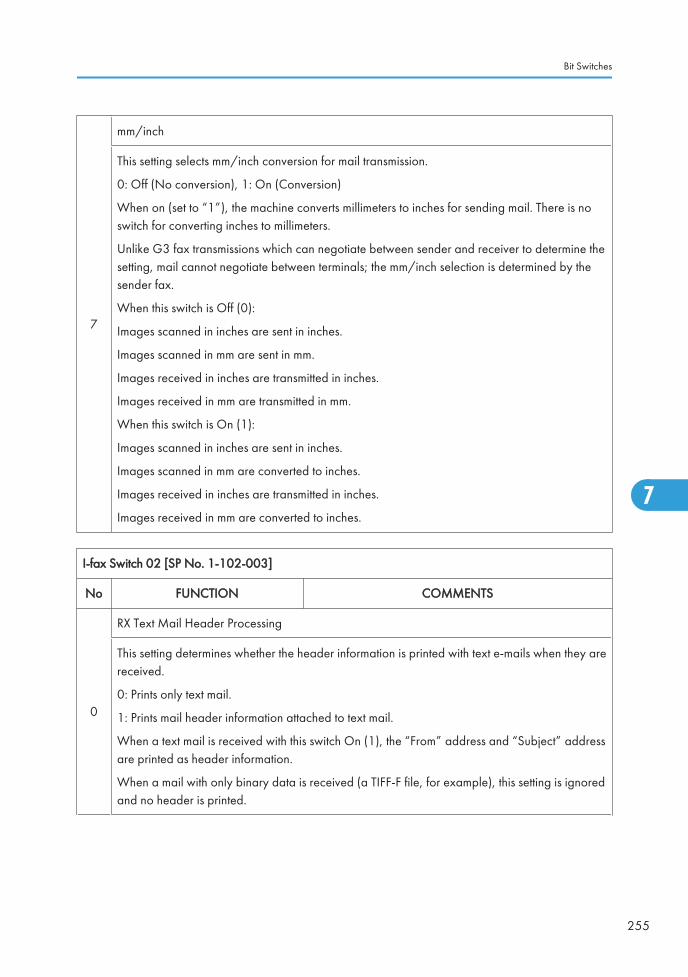
7
mm/inch
This setting selects mm/inch conversion for mail transmission.
0: Off (No conversion), 1: On (Conversion)
When on (set to “1”), the machine converts millimeters to inches for sending mail. There is noswitch for converting inches to millimeters.
Unlike G3 fax transmissions which can negotiate between sender and receiver to determine thesetting, mail cannot negotiate between terminals; the mm/inch selection is determined by thesender fax.
When this switch is Off (0):
Images scanned in inches are sent in inches.
Images scanned in mm are sent in mm.
Images received in inches are transmitted in inches.
Images received in mm are transmitted in mm.
When this switch is On (1):
Images scanned in inches are sent in inches.
Images scanned in mm are converted to inches.
Images received in inches are transmitted in inches.
Images received in mm are converted to inches.
I-fax Switch 02 [SP No. 1-102-003]
No FUNCTION COMMENTS
0
RX Text Mail Header Processing
This setting determines whether the header information is printed with text e-mails when they arereceived.
0: Prints only text mail.
1: Prints mail header information attached to text mail.
When a text mail is received with this switch On (1), the “From” address and “Subject” addressare printed as header information.
When a mail with only binary data is received (a TIFF-F file, for example), this setting is ignoredand no header is printed.
Bit Switches
255
7

1
Output from Attached Document at E-mail TX Error
This setting determines whether only the first page or all pages of an e-mail attachment are printedat the sending station when a transmission error occurs. This allows the customer to see whichdocuments have not reached their intended destinations if sent to the wrong e-mail addresses, forexample.
0: Prints 1st page only.
1: Prints all pages.
2-3
Text String for Return Receipt
This setting determines the text string output for the Return Receipt that confirms the transmissionwas received normally at the destination.
00: “Dispatched”
Sends from PC mail a request for a Return Receipt. Receives the Return Receipt with “dispatched”in the 2nd part:
Disposition: Automatic-action/MDN-send automatically; dispatched
The “dispatched” string is included in the Subject string.
01: “Displayed”
Sends from PC mail a request for a Return Receipt. Receives the Return Receipt with “displayed”in the 2nd part:
Disposition: Automatic-action/MDN-send automatically; displayed
The “displayed” string is included in the Subject string.
10: Reserved
11: Reserved
A mail requesting a Return Receipt sent from an IFAX with this switch set to “00” (for “dispatched”)received by Microsoft Outlook 2000 may cause an error. If any setting other than“displayed” (01) causes a problem, change the setting to “01” to enable normal sending of theReturn Receipt.
4
Media accept feature
This setting adds or does not add the media accept feature to the answer mail to confirm areception.
0: Does not add the media accept feature to the answer mail
1: Adds the media accept feature to the answer mail.
Use this bit switch if a problem occurs when the machine receives an answer mail, which containsthe media accept feature field.
7. Appendix: Fax Service Program (Only For D068/D069)
256
7

5-6 Not Used
7
Image Resolution of RX Text Mail
This setting determines the image resolution of the received mail.
0: 200 x 200
1: 400 x 400
The “1” setting requires installation of the Function Upgrade Card in order to have enough SAF(Store and Forward) memory to receive images at 400 x 400 resolution.
I-fax Switch 03 - Not used (do not change the settings) [ SP No. 1-102-004]
I-fax Switch 04 [SP No. 1-102-005]
No FUNCTION COMMENTS
0
Subject for Delivery TX/Memory Transfer
This setting determines whether the RTI/CSI registered on this machine or the RTI/CSI of theoriginator is used in the subject lines of transferred documents.
0: Puts the RTI/CSI of the originator in the Subject line. If this is used, either the RTI or CSI is used.Only one of these can be received for use in the subject line.
1: Puts the RTI/CSI registered on this machine in the Subject line.
When this switch is used to transfer and deliver mail to a PC, the information in the Subject linethat indicates where the transmission originated can be used to determine automatically thedestination folder for each e-mail.
1
Subject corresponding to mail post database
0: Standard subject
1: Mail post database subject
The standard subject is replaced by the mail post database subject in the following three cases:
1) When the service technician sets the service (software) switch.
2) When memory sending, delivery specified by F code or SMTP reception is done.
3) With relay broadcasting (1st stage without the Schmidt 4 function).
• This switch does not apply for condition 3) when the RX system is set up for memory sending,delivery by F-code, sending with SMTP RX and when operators are using FOL (to preventproblems when receiving transmissions).
Bit Switches
257
7

2-7 Not Used
I-fax Switch 05 [SP No. 1-102-006]
No FUNCTION COMMENTS
0 Mail Addresses of SMTP Broadcast Recipients
Determines whether the e-mail addresses of the destinations that receive transmissionsbroadcasted using SMTP protocol are recorded in the Journal.
For example:
"1st destination + Total number of destinations: 9" in the Journal indicates a broadcast to 9destinations.
0: Not recorded
1: Recorded
1 I-Fax Automatic Re-dial Setting
0: OFF
1: ON
Determines whether the I-fax automatically redials whenan error occurs.
2-7 Not used
I-fax Switch 06 - Not used (do not change the settings) [SP No. 1-102-007]
I-fax Switch 07 - Not used (do not change the settings) [SP No. 1-102-008]
I-fax Switch 08 [SP No. 1-102-009]
No FUNCTION COMMENTS
0-7
Memory Threshold for POP Mail Reception
This setting determines the amount of SAF (Store and Forward) memory. (SAF stores fax messagesto send later for transmission to more than one location, and also holds incoming messages if theycannot be printed.) When the amount of SAF memory available falls below this setting, mail canno longer be received; received mail is then stored on the mail server.
00-FF (0 to 1024 KB: HEX)
• The hexadecimal number you enter is multiplied by 4 KB to determine the amount of memory.
7. Appendix: Fax Service Program (Only For D068/D069)
258
7

I-fax Switch 09 [SP No. 1-102-010]
No FUNCTION COMMENTS
0-3 Not used Do not change the settings
4-7 Restrict TX Retries
This setting determines the number of retries whenconnection and transmission fails due to errors.
01-F (1-15 Hex)
I-fax Switch 0A - Not used (do not change the settings) [SP No. 1-102-011]
I-fax Switch 0B - Not used (do not change the settings) [SP No. 1-102-012]
I-fax Switch 0C - Not used (do not change the settings) [SP No. 1-102-013]
I-fax Switch 0D - Not used (do not change the settings) [SP No. 1-102-014]
I-fax Switch 0E - Not used (do not change the settings) [SP No. 1-102-015]
I-fax Switch 0F [SP No. 1-102-016]
No FUNCTION COMMENTS
0
Delivery Method for SMTP RX Files
This setting determines whether files received with SMTP protocol are delivered or outputimmediately.
0: Off. Files received via SMTP are output immediately without delivery.
1: On. Files received via SMTP are delivered immediately to their destinations.
1-7 Not used
Printer Switches
Printer Switch 00 [SP No. 1-103-001]
No FUNCTION COMMENTS
Bit Switches
259
7
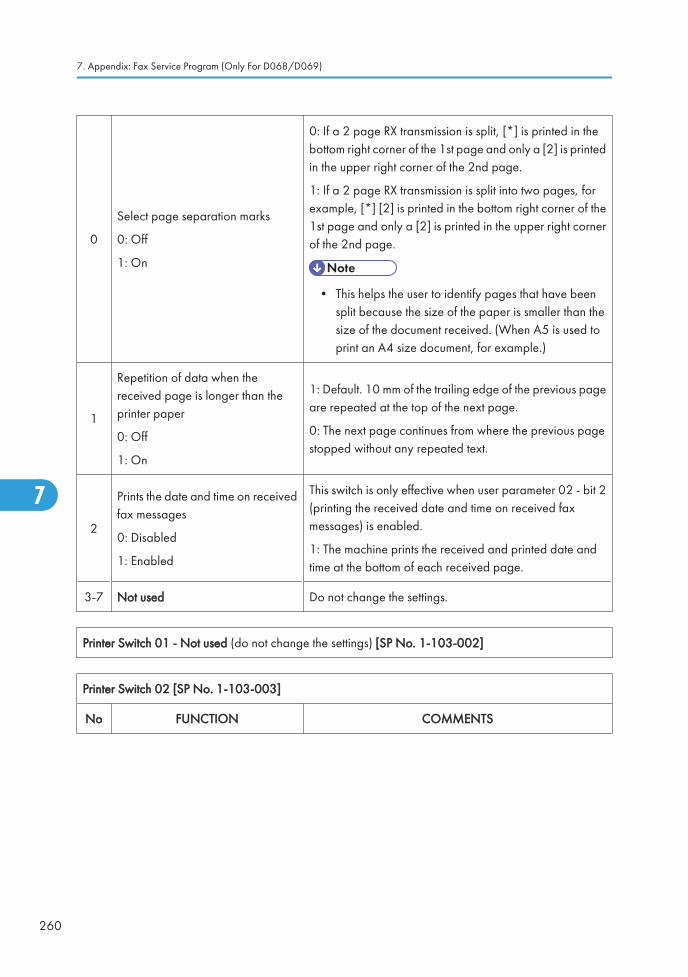
0
Select page separation marks
0: Off
1: On
0: If a 2 page RX transmission is split, [*] is printed in thebottom right corner of the 1st page and only a [2] is printedin the upper right corner of the 2nd page.
1: If a 2 page RX transmission is split into two pages, forexample, [*] [2] is printed in the bottom right corner of the1st page and only a [2] is printed in the upper right cornerof the 2nd page.
• This helps the user to identify pages that have beensplit because the size of the paper is smaller than thesize of the document received. (When A5 is used toprint an A4 size document, for example.)
1
Repetition of data when thereceived page is longer than theprinter paper
0: Off
1: On
1: Default. 10 mm of the trailing edge of the previous pageare repeated at the top of the next page.
0: The next page continues from where the previous pagestopped without any repeated text.
2
Prints the date and time on receivedfax messages
0: Disabled
1: Enabled
This switch is only effective when user parameter 02 - bit 2(printing the received date and time on received faxmessages) is enabled.
1: The machine prints the received and printed date andtime at the bottom of each received page.
3-7 Not used Do not change the settings.
Printer Switch 01 - Not used (do not change the settings) [SP No. 1-103-002]
Printer Switch 02 [SP No. 1-103-003]
No FUNCTION COMMENTS
7. Appendix: Fax Service Program (Only For D068/D069)
260
7

0
1st paper feed station usage for faxprinting
0: Enabled
1: Disabled
0: The paper feed station can be used to print fax messagesand reports.
1: The specified paper feed station will not be used forprinting fax messages and reports.
• Do not disable usage for a paper feed station whichhas been specified by User Parameter Switch 0F (15),or which is used for the Specified Cassette Selectionfeature.
1
2nd paper feed station usage forfax printing
0: Enabled
1: Disabled
2-7 Not used Do not change the settings.
Printer Switch 03 [SP No. 1-103-004]
No FUNCTION COMMENTS
0
Length reduction of received data
0: Disabled
1: Enabled
0: Incoming pages are printed without length reduction.
(Page separation threshold: Printer Switch 03, bits 4 to 7)
1: Incoming page length is reduced when printing.
(Maximum reducible length: Printer Switches 04, bits 0 to4)
1-3 Not used Do not change the settings
4-7
Page separation setting when subscan compression is forbidden
00-0F (0-15 mm: Hex)
Default: 6 mm
Page separation threshold (with reduction disabled withswitch 03-0 above).
For example, if this setting is set to "10", and A4 is theselected paper size:
If the received document is 10 mm or less longer than A4,then the 10 mm are cut and only 1 page prints.
If the received document is 10 mm longer than A4, then thedocument is split into 2 pages.
Printer Switch 04 SP No. 1-103-005
No FUNCTION COMMENTS
Bit Switches
261
7

0-4
Maximum reducible length when length reduction is enabled with switch 03-0 above.
<Maximum reducible length> = <Paper length> + (N x 5mm)
“N” is the decimal value of the binary setting of bits 0 to 4.
Bit 4 Bit 3 Bit 2 Bit 1 Bit 0 Setting
0 0 0 0 0 0 mm
0 0 0 0 1 5 mm
0 0 1 0 0 20 mm
1 1 1 1 1 155 mm
For A5 sideways and B5 sideways paper
<Maximum reducible length> = <Paper length> + 0.75 x (N x 5mm)
5-6
Length of the duplicated image on the next page, when page separation has taken place.
Bit 6: 0, Bit 5: 0 = 4 mm
Bit 6: 1, Bit 5: 0 = 10 mm
Bit 6: 0, Bit 5: 1 = 15 mm
Bit 6: 1, Bit 5: 1 = Not used
7 Not used. Do not change the setting.
Printer Switch 05 - Not used (do not change the settings)
Printer Switch 06 [SP No. 1-103-007]
No FUNCTION COMMENTS
0
Printing while a paper cassette ispulled out, when the Just SizePrinting feature is enabled.0: Printing will not start1: Printing will start if anothercassette has a suitable size ofpaper, based on the paper sizeselection priority tables.
Cross reference
Just size printing on/off – User switch 05, bit 5
1-7 Not used. Do not change the settings.
7. Appendix: Fax Service Program (Only For D068/D069)
262
7

Printer Switch 07 [SP No. 1-103-008]
No FUNCTION COMMENTS
0-3 Not used. Do not change the settings.
4
List of destinations in theCommunication Failure Report forbroadcasting
0: All destinations
1: Only destinations where
communication failure occurred
1: Only destinations where communication failure occurredare printed on the Communication Failure Report.
5-7 Not used. Do not change the settings.
Printer Switch 08 - Not used (do not change the settings) [SP No. 1-103-009]
Printer Switch 09 - Not used (do not change the settings) [SP No. 1-103-010]
Printer Switch 0A - Not used (do not change the settings) [SP No. 1-103-011]
Printer Switch 0B - Not used (do not change the settings) [SP No. 1-103-012]
Printer Switch 0C - Not used (do not change the settings) [SP No. 1-103-013]
Printer Switch 0D - Not used (do not change the settings) [SP No. 1-103-014]
Printer Switch 0E [SP No. 1-103-015]
No FUNCTION COMMENTS
0
Paper size selection priority
0: Width
1: Length
0: A paper size that has the same width as thereceived data is selected first.
1: A paper size which has enough length to print allthe received lines without reduction is selected first.
1
Paper size selected for printing A4 widthfax data
0: 8.5" x 11" size
1: A4 size
This switch determines which paper size is selectedfor printing A4 width fax data, when the machinehas both A4 and 8.5" x 11" size paper.
Bit Switches
263
7

2
Page separation
0: Enabled
1: Disabled
1: If all paper sizes in the machine require pageseparation to print a received fax message, themachine does not print the message (SubstituteReception is used).
After a larger size of paper is set in a cassette, themachine automatically prints the fax message.
3-4
Printing the sample image on reports
Bit 4: 0, Bit 3: 0 = The upper half only
Bit 4: 0, Bit 3: 1 = 50% reduction in sub-scan only
Bit 4: 1, Bit 3: 0 = Same size
Bit 4: 1, Bit 3: 1 = Not used
“Same size” means the sample image is printed at100%, even if page separation occurs.
User Parameter Switch 19 (13H) bit 4 must be setto “0” to enable this switch.
Refer to Detailed Section Descriptions for more onthis feature.
5-6 Not used Do not change the settings.
7
Equalizing the reduction ratio amongseparated pages
(Page Separation)
0: Enabled
1: Disabled
0: When page separation has taken place, all thepages are reduced with the same reduction ratio.
1: Only the last page is reduced to fit the selectedpaper size when page separation has taken place.Other pages are printed without reduction.
Printer Switch 0F [SP No. 1-103-016]
No FUNCTION COMMENTS
0-1
Smoothing feature
Bit 1: 0 Bit 0: 0 = Disabled
Bit 1: 0 Bit 0: 1 = Disabled
Bit 1: 1 Bit 0: 0 = Enabled
Bit 1: 1 Bit 0: 1 = Not used
(0, 0) (0, 1): Disable smoothing if the machine receiveshalftone images from other manufacturers fax machinesfrequently.
2-7 Not used Do not change the settings.
Communication Switches
Communication Switch 00 [SP No. 1-104-001]
No FUNCTION COMMENTS
7. Appendix: Fax Service Program (Only For D068/D069)
264
7

0-1
Compression modes available inreceive mode
Bit 1: 0 Bit 0: 0 = MH only
Bit 1: 0 Bit 0: 1 = MH/MR
Bit 1: 1 Bit 0: 0 = MH/MR/MMR
Bit 1: 1 Bit 0: 1 = MH/MR/MMR/JBIG
These bits determine the compression capabilities to bedeclared in phase B (handshaking) of the T.30 protocol.
2-3
Compression modes available intransmit mode
Bit 3: 0 Bit 2: 0 = MH only
Bit 3: 0 Bit 2: 1 = MH/MR
Bit 3: 1 Bit 2: 0 = MH/MR/MMR
Bit 3: 1 Bit 2: 1 = MH/MR/MMR/JBIG
These bits determine the compression capabilities to beused in the transmission and to be declared in phase B(handshaking) of the T.30 protocol.
4 Not used Do not change the settings.
5
JBIG compression method:Reception
0: Only basic supported
1: Basic and optional bothsupported
Change the setting when communication problems occurusing JBIG compression.
6
JBIG compression method:Transmission
0: Basic mode priority
1: Optional mode priority
Change the setting when communication problems occurusing JBIG compression.
7 Not used Do not change the settings.
Communication Switch 01 [SP No. 1-104-002]
No FUNCTION COMMENTS
0ECM0: Off 1: On
If this bit is set to 0, ECM is switched off for allcommunications.
In addition, V.8 protocol and JBIG compression areswitched off automatically.
1-5 Not used Do not change the setting.
Bit Switches
265
7

6-7
Maximum printable page lengthavailable
Bit 7: 0 Bit 6: 0 = No limit
Bit 7: 0 Bit 6: 1 = B4 (364 mm)
Bit 7: 1 Bit 6: 0 = A4 (297 mm)
Bit 7: 1 Bit 6: 1 = Not used
The setting determined by these bits is informed to thetransmitting terminal in the pre-message protocol exchange(in the DIS/NSF frames).
Communication Switch 02 [SP No. 1-104-003]
No FUNCTION COMMENTS
0G3 Burst error threshold
0: Low 1: High
If there are more consecutive error lines in the receivedpage than the threshold, the machine will send a negativeresponse. The Low and High threshold values depend onthe sub-scan resolution, and are as follows.
100 dpi 6(L) Õ 12(H)
200 dpi 12(L) Õ 24(H)
300 dpi 18(L) Õ 36(H)
400 dpi 24(L) Õ 48(H)
1Acceptable total error line ratio
0: 5% 1: 10%
If the error line ratio for a page exceeds the acceptableratio, RTN will be sent to the other end.
2
Treatment of pages received witherrors during G3 reception
0: Deleted from memory withoutprinting
1: Printed
0: Pages received with errors are not printed.
3
Hang-up decision when a negativecode (RTN or PIN) is receivedduring G3 immediate transmission
0: No hang-up, 1: Hang-up
0: The next page will be sent even if RTN or PIN is received.
1: The machine will send DCN and hang up if it receivesRTN or PIN.
This bit is ignored for memory transmissions or if ECM isbeing used.
4-7 Not used Do not change the settings.
Communication Switch 03 [SP No. 1-104-004]
7. Appendix: Fax Service Program (Only For D068/D069)
266
7

No FUNCTION COMMENTS
0-7Maximum number of pageretransmissions in a G3 memorytransmission
00 - FF (Hex) times.
This setting is not used if ECM is switched on.
Default setting - 03(H)
Communication Switch 04 - Not used (do not change the settings)
Communication Switch 05 - Not used (do not change the settings)
Communication Switch 06 - Not used (do not change the settings)
Communication Switch 07 - Not used (do not change the settings)
Communication Switch 08 - Not used (do not change the settings)
Communication Switch 09 [SP No. 1-104-010]
No FUNCTION COMMENTS
0-7 I-Fax dial interval setting
Adjusts the interval of the I-fax dialing.
The interval of I-fax dialing is calculated by followingformula.
[Interval time = specified value with this switch x 2 sec]
Communication Switch 0A [SP No. 1-104-011]
No FUNCTION COMMENTS
0
Point of resumption of memorytransmission upon redialing
0: From the error page
1: From page 1
0: The transmission begins from the page wheretransmission failed the previous time.
1: Transmission begins from the first page, using normalmemory transmission.
1-7 Not used Do not change the settings.
Communication Switch 0B – Not used (do not change the settings)
Communication Switch 0C – Not used (do not change the settings)
Communication Switch 0D [SP No. 1-104-014]
Bit Switches
267
7

No FUNCTION COMMENTS
0-7
The available memory threshold,below which ringing detection (andtherefore reception into memory) isdisabled
00 to FF (Hex), unit = 4 kbytes
(e.g., 06(H) = 24 kbytes)
One page is about 24 kbytes.
The machine refers to this setting before each fax reception.If the amount of remaining memory is below this threshold,the machine cannot receive any fax messages.
If this setting is kept at 0, the machine will detect ringingsignals and go into receive mode even if there is no memoryavailable. This will result in communication failure.
Communication Switch 0E [SP No. 1-104-015]
No FUNCTION COMMENTS
0-7Minimum interval betweenautomatic dialing attempts
06 to FF (Hex), unit = 2 s
(e.g., 06(H) = 12 s)
This value is the minimum time that the machine waits beforeit dials the next destination.
Communication Switch 0F – Not used (do not change the settings.)
Communication Switch 10 [SP No. 1-104-017]
No FUNCTION COMMENTS
0-7Memory transmission: Maximumnumber of dialing attempts to thesame destination
01 – FE (Hex) times
Communication Switch 11 – Not used (do not change the settings.)
Communication Switch 12 [SP No. 1-104-019]
No FUNCTION COMMENTS
0-7Memory transmission: Intervalbetween dialing attempts to thesame destination
01 – FF (Hex) minutes
7. Appendix: Fax Service Program (Only For D068/D069)
268
7

Communication Switch 13 – Not used (do not change the settings.)
Communication Switch 14 [SP No. 1-104-021]
No FUNCTION COMMENTS
0
Inch-to-mm conversion duringtransmission
0: Disabled 1: Enabled
0: In immediate transmission, data scanned in inch formatare transmitted without conversion.
In memory transmission, data stored in the SAF memory inmm format are transmitted without conversion.
Note: When storing the scanned data into SAF memory,the fax unit always converts the data into mm format.
1: The machine converts the scanned data or stored datain the SAF memory to the format which was specified in theset-up protocol (DIS/NSF) before transmission.
1-5 Not used Do not change the factory settings.
6-7
Available unit of resolution in whichfax messages are received
Bit 7: 0, Bit 6: 0 = mm
Bit 7: 0, Bit 6: 1 = inch
Bit 7: 1, Bit 6: 0 = mm and inch(default)
Bit 7: 1, Bit 6: 1 = Not used
For the best performance, do not change the factorysettings.
The setting determined by these bits is informed to thetransmitting terminal in the pre-message protocol exchange(in the DIS/NSF frames).
Communication Switch 15 – Not used (do not change the settings)
Communication Switch 16 – Not used (do not change the settings)
Communication Switch 17 – Not used (do not change the settings)
Communication Switch 18 - Not used (do not change the settings)
Communication Switch 19 - Not used (do not change the settings)
Communication Switch 1A - Not used (do not change the settings)
Communication Switch 1B [SP No. 1-104-028]
No FUNCTION COMMENTS
Bit Switches
269
7

0-7
Extension access code (0 to 7) toturn V.8 protocol On/Off
0: On
1: Off
If the PABX does not support V.8/V.34 protocol procedure,set this bit to “1” to disable V.8.
Example: If “0” is the PSTN access code, set bit 0 to 1.When the machine detects “0” as the first dialed number,it automatically disables V.8 protocol. (Alternatively, if “3”is the PSTN access code, set bit 3 to 1.)
Communication Switch 1C [SP No. 1-104-029]
No FUNCTION COMMENTS
0-1
Extension access code (8 and 9) toturn V.8 protocol On/Off0: On
1: Off
Refer to communication switch 1B.
Example: If “8” is the PSTN access code, set bit 0 to 1.When the machine detects “8” as the first dialed number,it automatically disables V.8 protocol. (If “9” is the PSTNaccess code, use bit 1.)
2-7 Not used Do not change the settings.
Communication Switch 1D - Not used (do not change the settings)
Communication Switch 1E - Not used (do not change the settings)
Communication Switch 1F - Not used (do not change the settings)
G3-1 Switches
G3 Switch 00 [SP No. 1-105-001]
No FUNCTION COMMENTS
0-1
Monitor speaker duringcommunication (tx and rx)
Bit 1: 0, Bit 0: 0 = Disabled
Bit 1: 0, Bit 0: 1 = Up to Phase B
Bit 1: 1, Bit 0: 0 = All the time
Bit 1: 1, Bit 0: 1 = Reserved
(0, 0): The monitor speaker is disabled all through thecommunication.
(0, 1): The monitor speaker is on up to phase B in the T.30protocol.
(1, 0): Used for testing. The monitor speaker is on all throughthe communication. Make sure that you reset these bits aftertesting.
7. Appendix: Fax Service Program (Only For D068/D069)
270
7

2
Monitor speaker during memorytransmission
0: Disabled 1: Enabled
1: The monitor speaker is enabled during memorytransmission.
3-7 Not used Do not change the settings.
G3 Switch 01 [SP No. 1-105-002]
No FUNCTION COMMENTS
0-3 Not used Do not change the settings.
4DIS frame length
0: 10 bytes 1: 4 bytes
1: The bytes in the DIS frame after the 4th byte will not betransmitted (set to 1 if there are communication problemswith PC-based faxes which cannot receive the extendedDIS frames).
5 Not used Do not change the setting.
6
Forbid CED/AMsam output
0: Off
1: On (Forbid output)
Do not change this setting (Default: 0: Off), unlesscommunication problem is caused by a CED or ANSamtransmission.
7 Not used Do not change the setting.
G3 Switch 02 [SP No. 1-105-003]
No FUNCTION COMMENTS
0
G3 protocol mode used
0: Standard and non-standard
1: Standard only
Change this bit to 1 only when the other end can onlycommunicate with machines that send T.30-standardframes only.
1: Disables NSF/NSS signals (these are used in non-standard mode communication)
1-6 Not used Do not change the settings.
7Short preamble
0: Disabled 1: Enabled
Refer to Appendix B in the Group 3 Facsimile Manual fordetails about Short Preamble.
G3 Switch 03 [SP No. 1-105-004]
No FUNCTION COMMENTS
Bit Switches
271
7

0
DIS detection number
(Echo countermeasure)
0: 1
1: 2
0: The machine will hang up if it receives the same DIS frametwice.
1: Before sending DCS, the machine will wait for the secondDIS which is caused by echo on the line.
1 Not Used Do not change the settings.
2
V.8 protocol
0: Disabled
1: Enabled
0: V.8/V.34 communications will not be possible.
Note:
Do not set to 0 unless the line condition is always badenough to slow down the data rate to 14.4 kbps or lower.
3
ECM frame size
0: 256 bytes
1: 64 bytes
Keep this bit at “0” in most cases.
4
CTC transmission conditions
0: After one PPR signal received
1: After four PPR signals received(ITU-T standard)
0: When using ECM in non-standard (NSF/NSS) mode,the machine sends a CTC to drop back the modem rate afterreceiving a PPR, if the following condition is met incommunications at 14.4, 12.0, 9.6, and 7.2 kbps.
NTransmit- Number of transmitted frames
NResend- Number of frames to be retransmitted
1: When using ECM, the machine sends a CTC to dropback the modem rate after receiving four PPRs.
PPR, CTC: These are ECM protocol signals.
This bit is not effective in V.34 communications.
5
Modem rate used for the next pageafter receiving a negative code(RTN or PIN)
0: No change 1: Fallback
1: The machine’s tx modem rate will fall back beforesending the next page if a negative code is received. Thisbit is ignored if ECM is being used.
6 Not Used Do not change the settings
7. Appendix: Fax Service Program (Only For D068/D069)
272
7

7
Select detection of reverse polarityin ringing
0: Off
1: On
This switch is used to prevent reverse polarity in ringing onthe phone line (applied to PSTN-G3 ringing). Do notchange this setting
0: No detection Outside Japan
1: Detection Inside Japan only
G3 Switch 04 [SP No. 1-105-005]
No FUNCTION COMMENTS
0-3 Training error detection threshold 0 - F (Hex); 0 - 15 bits
If the number of error bits in the received TCF is below thisthreshold, the machine informs the sender that training hassucceeded.
4-7 Not used Do not change the settings.
G3 Switch 05 [SP No. 1-105-006]
No FUNCTION COMMENTS
Bit Switches
273
7

0-3
Initial Tx modem rate
These bits set the initial starting modem rate fortransmission.
Use the dedicated transmission parameters if you needto change this for specific receivers.
If a modem rate 14.4 kbps or slower is selected, V.8protocol should be disabled manually.
Cross reference
V.8 protocol on/off - G3 switch 03, bit2
Bit 3 Bit 2 Bit 1 Bit 0 bps
0 0 0 1 2.4k
0 0 1 0 4.8k
0 0 1 1 7.2k
0 1 0 0 9.6k
0 1 0 1 12.0k
0 1 1 0 14.4k
0 1 1 1 16.8k
1 0 0 0 19.2k
1 0 0 1 21.6k
1 0 1 0 24.0k
1 0 1 1 26.4k
1 1 0 0 28.8k
1 1 0 1 31.2k
1 1 1 0 33.6k
Other settings - Not used
4-5
Initial modem type for 9.6 k or 7.2kbps.
Bit 5: 0, Bit 4: 0 = V.29
Bit 5: 0, Bit 4: 1 = V.17
Bit 5: 1, Bit 4: 0 = V.34
Bit 5: 1, Bit 4: 1 = Reserved
These bits set the initial modem type for 9.6 and 7.2 kbps,if the initial modem rate is set at these speeds.
6-7 Not used Do not change the settings.
G3 Switch 06 [SP No. 1-105-007]
No FUNCTION COMMENTS
7. Appendix: Fax Service Program (Only For D068/D069)
274
7

0-3
Initial Rx modem rate
• These bits set the initial starting modem ratefor reception.
• Use a lower setting if high speeds poseproblems during reception.
• If a modem rate 14.4 kbps or slower isselected, V.8 protocol should be disabledmanually.
Cross reference:
V.8 protocol on/off - G3 switch 03, bit2
Bit 3 Bit 2 Bit 1 Bit 0 bps
0 0 0 1 2.4k
0 0 1 0 4.8k
0 0 1 1 7.2k
0 1 0 0 9.6k
0 1 0 1 12.0k
0 1 1 0 14.4k
0 1 1 1 16.8k
1 0 0 0 19.2k
1 0 0 1 21.6k
1 0 1 0 24.0k
1 0 1 1 26.4k
1 1 0 0 28.8k
1 1 0 1 31.2k
1 1 1 0 33.6k
Other settings - Not used
Bit Switches
275
7

4-7
Modem types available for reception
• The setting of these bits is used to inform thetransmitting terminal of the available modemtype for the machine in receive mode.
• If V.34 is not selected, V.8 protocol must bedisabled manually.
Cross reference:
V.8 protocol on/off - G3 switch 03, bit2
Bit 7 Bit 6 Bit 5 Bit 4 Setting
0 0 0 1 V.27ter
0 0 1 0 V.27ter,V.29
0 0 1 1V.27ter, V.29,V.33
0 1 0 0V.27ter, V.29,
V.17/V.33
0 1 0 1V.27ter, V.29,V.17/V33, V.34
Other settings - Not used
G3 Switch 07 [SP No. 1-105-008]
No FUNCTION COMMENTS
0-1
PSTN cable equalizer
(tx mode: Internal)
Bit 1: 0, Bit 0: 0 = None
Bit 1: 0, Bit 0: 1 = Low
Bit 1: 1, Bit 0: 0 = Medium
Bit 1: 1, Bit 0: 1 = High
Use a higher setting if there is signal loss at higher frequenciesbecause of the length of wire between the modem and thetelephone exchange.
Use the dedicated transmission parameters for specificreceivers.
Also, try using the cable equalizer if one or more of thefollowing symptoms occurs.
Communication error
Modem rate fallback occurs frequently.
• This setting is not effective in V.34 communications.
7. Appendix: Fax Service Program (Only For D068/D069)
276
7

2-3
PSTN cable equalizer
(rx mode: Internal)
Bit 3: 0, Bit 2: 0 = None
Bit 3: 0, Bit 2: 1 = Low
Bit 3: 1, Bit 2: 0 = Medium
Bit 3: 1, Bit 2: 1 = High
Use a higher setting if there is signal loss at higher frequenciesbecause of the length of wire between the modem and thetelephone exchange.
Also, try using the cable equalizer if one or more of thefollowing symptoms occurs.
Communication error with error codes such as
0-20, 0-23, etc.
Modem rate fallback occurs frequently.
• This setting is not effective in V.34 communicatio
4
PSTN cable equalizer
(V.8/V.17 rx mode: External)
0: Disabled
1: Enabled
Keep this bit at “1”.
5 Not used Do not change the settings.
6
Parameter selection for dial tonedetection
0: Normal parameter
1: Specific parameter
0: This uses the fixed table in the ROM for dial tone detection.
1: This uses the specific parameter adjusted with SRAM(69ECBEH - 69ECDEH). Select this if the dial tone cannot bedetected when the "Normal parameter: 0" is selected.
7 Not used Do not change the settings.
G3 Switch 08 - Not used (do not change the settings)
G3 Switch 09 - Not used (do not change the settings)
G3 Switch 0A [SP No. 1-105-011]
No FUNCTION COMMENTS
Bit Switches
277
7

0-1
Maximum allowable carrier dropduring image data reception
Bit 1: 0, Bit 0: 0 = 200
Bit 1: 0, Bit 0: 1 = 400
Bit 1: 1, Bit 0: 0 = 800
Bit 1: 1, Bit 0: 1 = Reserved
These bits set the acceptable modem carrier drop time.
Try using a longer setting if error code 0-22 is frequent.
2
Select cancellation of high-speed RXif carrier signal lost while receiving
0: Off
1: On
This switch setting determines if high-speed receivingends if the carrier signal is lost when receiving duringnon-ECM mode
3 Not used Do not change the settings
4
Maximum allowable frame intervalduring image data reception.
0: 5 s 1: 13 s
This bit set the maximum interval between EOL (end-of-line) signals and the maximum interval between ECMframes from the other end.
Try using a longer setting if error code 0-21 is frequent.
5 Not used Do not change the settings.
6
Reconstruction time for the first line inreceive mode
0: 6 s 1: 12 s
When the sending terminal is controlled by a computer,there may be a delay in receiving page data after thelocal machine accepts set-up data and sends CFR. Thisis outside the T.30 recommendation. But, if this delayoccurs, set this bit to 1 to give the sending machine moretime to send data.
Refer to error code 0-20.
ITU-T T.30 recommendation: The first line should comewithin 5 s of CFR.
7 Not used Do not change the settings.
G3 Switch 0B Not used (do not change the settings).
G3 Switch 0C Not used (do not change the settings).
G3 Switch 0D Not used (do not change the settings).
G3 Switch 0E [SP No 1-105-015]
7. Appendix: Fax Service Program (Only For D068/D069)
278
7

0-7
Set CNG send time interval
Some machines on the receiving side may not be able to automatically switch the 3-second CNGinterval.
High order bit3000-2250ms: 3000-50xNms
3000 – 50 x Nms 0F (3000 ms) ≤ N ≤ FF (2250 ms)
Low order bit00-0E(3000-3700ms: 3000+50xNms
3000 – 50 x Nms 0F (3000 ms) ≤ N ≤ 0F (3700 ms)
G3 Switch 0F [SP No. 1-105-016]
No FUNCTION COMMENTS
0
Alarm when an error occurred inPhase C or later
0: Disabled
1: Enabled
If the customer wants to hear an alarm after each errorcommunication, change this bit to “1”.
1
Alarm when the handset is off-hookat the end of communication
0: Disabled
1: Enabled
If the customer wants to hear an alarm if the handset is off-hook at the end of fax communication, change this bit to“1”.
2-3 Not used Do not change the settings.
4
Sidaa manual calibration setting
0: Off
1: On
1: manually calibrates for communication with a line,whose current change occurs such as an optical fiber line.
5-6 Not used Do not change the settings.
IP Fax Switches
IP Fax Switch 00 [SP No. 1-111-001]
No. FUNCTION COMMENTS
0 Not used Do not change this setting.
Bit Switches
279
7

1IP Fax Transport
0: TCP, 1: UDPSelects TCP or UDP protocol for IP-Fax
2IP Fax single port selection
0: OFF, 1: ON (enable)Selects single data port.
3
IP Fax double ports (single data port)selection
0: OFF, 1: ON (enable)
Selects whether IP-Fax uses a double port.
4IP Fax Gatekeeper
0: OFF, 1: ON (enable)
Enables/disables the communication via thegatekeeper for IP-Fax.
5IP Fax T30 bit signal reverse
0: LSB first, 1: MSB firstReverses the T30 bit signal.
6IP Fax max bit rate setting
0: Not affected, 1: Affected
When "0" is selected, the max bit rate does not affectthe value of the DIS/DCS.
When "1" is selected, the max bit rate affects thevalue of the DIS/DCS.
7
IP Fax received telephone numberconfirmation
0: No confirmation,
1: Confirmation
When "0" is selected, fax data is received withoutchecking the telephone number.
When "1" is selected, fax data is received only whenconfirming that the telephone number from thesender matches the registered telephone number inthis machine. If this confirmation fails, the line isdisconnected.
IP-Fax Switch 01
No. FUNCTION COMMENTS
7. Appendix: Fax Service Program (Only For D068/D069)
280
7

0-3
Select IP FAX Delay Level Raise the level by selecting a higher setting if toomany transmission errors are occurring on thenetwork.
If TCP/UDP is enabled on the network, raise thissetting on the T.30 machine. Increasing the delaytime allows the recovery of more lost packets.
If only UDP is enabled, increase the number ofredundant packets.
Level 1 to 2: 3 Redundant packets
Level 3: 4 Redundant packets
Bit3 Bit2 Bit1 Bit0 Setting
0 0 0 0 Level 0
0 0 0 1 Level 1
0 0 1 0 Level 2
0 0 1 1 Level 3
4-7 IP Fax preamble wait time setting
Selects the preamble wait time.
[00 to 0f]
There are 16 values in this 4-bit binary switchcombination.
Waiting time: set value level x 100 ms
Max: 0f (1500 ms) Min: 00 (No wait time)
The default is "0000" (00H).
IP Fax Switch 02 [SP No. 1-111-003]
No. FUNCTION COMMENTS
0
IP Fax bit signal reverse setting
0: Maker code setting
1: Internal bit switch setting
When "0" is selected, the bit signal reverse methodis decided by the maker code.
When "1" is selected, the bit signal reverse methodis decided by the internal bit switch.
(When communicating between IP Fax devices, LSBfirst is selected.)
1
IP Fax transmission speed setting
0: Modem speed
1: No limitation
Selects the transmit speed for IP Fax communication.
2
SIP transport setting
0: TCP
1: UDP
This bit switch sets the transport that has priority forreceiving IP Fax data.
This function is activated only when the sender hasboth TCP and UDP.
Bit Switches
281
7

3
CCM connection
0: No CCM connection
1: CCM connection
When "1" is selected, only the connection callmessage with H.323 or no tunneled H.245 istransmitted via CCM.
4
Message reception selection from non-registered SIP server
0: Answer
1: Not answer
0: This answers the INVITE message from the SIPserver not registered for the machine.
1: This does not receive the INVITE message from theSIP server not registered for the machine and send arefusal message.
5
ECM communication setting
0: No limit for image compression
1: Limit for image compression
0: This does not limit the type of the imagecompression with ECM communication.
1: When the other end machine is Ciscco, this permitsthe image compression other than JBIG or MMR withECM communication.
6-7 Not used Do not change these settings.
IP Fax Switch 03 [SP No. 1-111-004]
No. FUNCTION COMMENTS
0
Effective field limitation for G3 standardfunction information
0: OFF, 1: 4byte (DIS)
Limits the effective field for standard G3 functioninformation.
1
Switching between G3 standard andG3 non standard
0: Enable switching
1: G3 standard only
Enables/disables switching between G3 standardand G3 non-standard.
2 Not used. Do not change this setting.
3ECM frame size selection at transmitting
0: 256byte, 1: 64byteSelects the ECM frame size for sending.
4DIS detection times for echo prevention
0: 1 time, 1: 2 timesSets the number of times for DIS to detect echoes.
7. Appendix: Fax Service Program (Only For D068/D069)
282
7

5
CTC transmission selection
0: PPRx1
1: PPRx4
When "0" is selected, the transmission condition isdecided by error frame numbers.
When "1" is selected, the transmission condition isbased on the ITU-T method.
6
Shift down setting at receiving negativecode
0: OFF, 1: ON
Selects whether to shift down when negative codesare received.
7 Not used Do not change this setting.
IP Fax Switch 04 [SP No. 1-111-005]
No. FUNCTION COMMENTS
0
TCF error threshold
Sets the TCF error threshold level.
[00 to 0f]
The default is "1111" (0fH).
1
2
3
4-7 Not used Do not change these settings.
IP Fax Switch 05 [SP No. 1-111-006]
No. FUNCTION COMMENTS
Bit Switches
283
7

0-3
Modem bit rate setting for transmission
Sets the modem bit rate for transmission. The default is "0110" (14.4K bps).
Bit 4 Bit 3 Bit 2 Bit 1
0 0 0 1 2400 bps
0 0 1 1 4800 bps
0 0 1 1 7200 bps
0 1 0 0 9600 bps
0 1 0 1 12.0 Kbps
0 1 1 0 14.4 Kbps
0 1 1 1 16.8 Kbps
1 0 0 0 19.2 Kbps
1 0 0 1 21.6 Kbps
1 0 1 0 24.0 Kbps
1 0 1 1 26.4 Kbps
1 1 0 0 28.8 Kbps
1 1 0 1 31.2 Kbps
1 1 1 0 33.6 Kbps
4-5
Modem setting for transmission
Sets the modem for transmission.
The default is "00" (V29).
Bit 5: 0, Bit 4: 0 = V29
Bit 5: 0, Bit 4: 1 = V17
Bit 5: 1, Bit 4: 0 = V34*
Bit 5: 1, Bit 4: 1 = Not used
*V34 is not supported for IP-Fax communication.
6-7 Not used Do not change these settings.
IP Fax Switch 06 [SP No. 1-111-007]
7. Appendix: Fax Service Program (Only For D068/D069)
284
7

No. FUNCTION COMMENTS
0-3
Modem bit rate setting for reception
Sets the modem bit rate for reception. The default is "0110" (14.4K bps).
Bit 3 Bit 2 Bit 1 Bit 0
0 0 0 1 2400 bps
0 0 1 0 4800 bps
0 0 1 1 7200 bps
0 1 0 0 9600 bps
0 1 0 1 12.0 Kbps
0 1 1 0 14.4 Kbps
0 1 1 1 16.8 Kbps
1 0 0 0 19.2 Kbps
1 0 0 1 21.6 Kbps
1 0 1 0 24.0 Kbps
1 0 1 1 26.4 Kbps
1 1 0 0 28.8 Kbps
1 1 0 1 31.2 Kbps
1 1 1 0 33.6 Kbps
Bit Switches
285
7

4-7
Modem setting for reception
Sets the modem type for reception. The default is "0100" (V27ter, V29, V17).
Bit 7 Bit 6 Bit 5 Bit 4
0 0 0 1 V27ter
0 0 1 0 V27ter, V29
0 0 1 1V27ter, V29, V33(invalid)
0 1 0 0 V27ter, V29, V17
0 1 0 1V27ter, V29, V17,V34*
*V34 is not supported for IP-Fax communication.
IP Fax Switch 07 [SP No. 1-111-008]
No. FUNCTION COMMENTS
0TSI information
0: Not added, 1: AddedAdds or does not add TSI information to NSS(S).
1
DCN transmission setting at T1 timeout
0: Not transmitted,
1: Transmitted
Transmits or does not transmit DCN at T1 timeout.
2 Not used Do not change this setting.
3
Hang up setting at DIS receptiondisabled
0: No hang up
1: Hang up after transmitting DCN
Sets whether the machine disconnects after DISreception.
4Number of times for training
0: 1 time, 1: 2 times
Selects the number of times training is done at thesame bit rate.
5
Space CSI transmission setting at no CSIregistration
0: Not transmitted,
1: Transmitted
When "0" is selected, frame data is enabled.
When "1" is selected, the transmitted data is allspaces.
7. Appendix: Fax Service Program (Only For D068/D069)
286
7

6-7 Not used Do not change these settings.
IP Fax Switch 08 [SP No. 1-111-009]
No. FUNCTION COMMENTS
0-1
T1 timer adjustment
Adjusts the T1 timer.
The default is "00" (35 seconds).
Bit 1: 0, Bit 0: 0 = 35 sec
Bit 1: 0, Bit 0: 1 = 40 sec
Bit 1: 1, Bit 0: 0 = 50 sec
Bit 1: 1, Bit 0: 1 = 60 sec
-
2-3
T4 timer adjustment
Adjust the T4 timer.
The default is "00" (3 seconds).
Bit 3: 0, Bit 2: 0 = 3 sec
Bit 3: 0, Bit 2: 1 = 3.5 sec
Bit 3: 1, Bit 2: 0 = 4 sec
Bit 3: 1, Bit 2: 1 = 5 sec
-
4-5
T0 timer adjustment
Bit 5: 0, Bit 4: 0 = 75 sec
Bit 5: 0, Bit 4: 1 = 120 sec
Bit 5: 1, Bit 4: 0 = 180 sec
Bit 5: 1, Bit 4: 1 = 240 sec
Adjusts the fail safe timer. This timer sets the intervalbetween "setup" data transmission and T.38 phasedecision. If your destination return is late on thenetwork or G3 fax return is late, adjust the longerinterval timer.
The default is "00" (75 seconds).
6-7 Not used Do not change these settings.
Bit Switches
287
7

NCU Parameters• This section is used only for F/SPF models (D068/D069).
• The following tables give the RAM addresses and the parameter calculation units that the machineuses for ringing signal detection and automatic dialing. The factory settings for each country are alsogiven. Most of these must be changed by RAM read/write (SP2-102), but some can be changedusing NCU Parameter programming (SP2-103); if SP2-103 can be used, this will be indicated in theRemarks column. The RAM is programmed in hex code unless (BCD) is included in the Unit column.
7. Appendix: Fax Service Program (Only For D068/D069)
288
7

Address Function
680500
Country/Area code for NCU parameters
Use the Hex value to program the country/area code directly into this address, or usethe decimal value to program it using SP2-103-001
Country
/AreaDecimal Hex
Country
/AreaDecimal Hex
France 00 00 USA 17 11
Germany 01 01 Asia 18 12
UK 02 02 Hong Kong 20 14
Italy 03 03 South Africa 21 15
Austria 04 04 Australia 22 16
Belgium 05 05 New Zealand 26 17
Denmark 06 06 Singapore 24 18
Finland 07 07 Malaysia 25 19
Ireland 08 08 China 26 1A
Norway 09 09 Taiwan 27 1B
Sweden 10 0A Korea 28 1C
Switzerland 11 0B Turkey 32 20
Portugal 12 0C Greece 33 21
Holland 13 0D Hungary 34 22
Spain 14 0E Czech 35 23
Israel 15 0F Poland 36 24
Address Function Unit Remarks
680501 Line current detection time
20 ms
Line current detection isdisabled.
Line current is not detected if680501 contains FF.
680502 Line current wait time
680503 Line current drop detect time
NCU Parameters
289
7

Address Function Unit Remarks
680504PSTN dial tone frequency upper limit(high byte)
Hz (BCD)If both addresses contain FF(H), tone detection isdisabled.680505
PSTN dial tone frequency upper limit(low byte)
680506PSTN dial tone frequency lower limit(high byte)
Hz (BCD)If both addresses contain FF(H), tone detection isdisabled.680507
PSTN dial tone frequency lower limit(low byte)
680508 PSTN dial tone detection time
20 ms
If 680508 contains FF(H),the machine pauses for thepause time (address68050D / 68050E).
Italy: See Note 2.
680509 PSTN dial tone reset time (LOW)
68050A PSTN dial tone reset time (HIGH)
68050B PSTN dial tone continuous tone time
68050C PSTN dial tone permissible drop time
68050D PSTN wait interval (LOW)-
68050E PSTN wait interval (HIGH)
68050F PSTN ring-back tone detection time 20 msDetection is disabled if thiscontains FF.
680510 PSTN ring-back tone off detection time 20 ms -
680511PSTN detection time for silent periodafter ring-back tone detected (LOW)
20 ms -
680512PSTN detection time for silent periodafter ring-back tone detected (HIGH)
20 ms -
680513PSTN busy tone frequency upper limit(high byte)
Hz (BCD)If both addresses contain FF(H), tone detection isdisabled.680514
PSTN busy tone frequency upper limit(low byte)
7. Appendix: Fax Service Program (Only For D068/D069)
290
7

Address Function Unit Remarks
680515PSTN busy tone frequency lower limit(high byte)
Hz (BCD)If both addresses contain FF(H), tone detection isdisabled.680516
PSTN busy tone frequency lower limit(low byte)
680517PABX dial tone frequency upper limit(high byte)
Hz (BCD)If both addresses contain FF(H), tone detection isdisabled.680518
PABX dial tone frequency upper limit(low byte)
680519PABX dial tone frequency lower limit(high byte)
Hz (BCD)If both addresses contain FF(H), tone detection isdisabled.68051A
PABX dial tone frequency lower limit(low byte)
68051B PABX dial tone detection time
20 ms
If 68051B contains FF, themachine pauses for thepause time (680520 /680521).
68051C PABX dial tone reset time (LOW)
68051D PABX dial tone reset time (HIGH)
68051E PABX dial tone continuous tone time
68051F PABX dial tone permissible drop time
680520 PABX wait interval (LOW)-
680521 PABX wait interval (HIGH)
680522 PABX ringback tone detection time 20 ms If both addresses contain FF(H), tone detection isdisabled.680523 PABX ringback tone off detection time 20 ms
680524PABX detection time for silent periodafter ringback tone detected (LOW)
20 ms If both addresses contain FF(H), tone detection isdisabled.680525
PABX detection time for silent periodafter ringback tone detected (HIGH)
20 ms
NCU Parameters
291
7
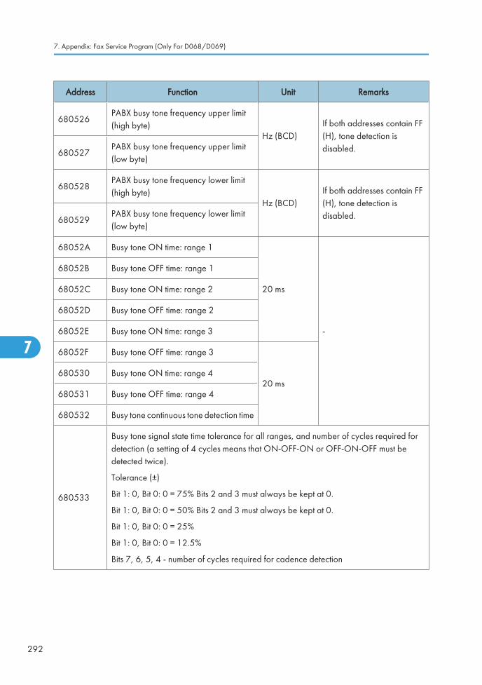
Address Function Unit Remarks
680526PABX busy tone frequency upper limit(high byte)
Hz (BCD)If both addresses contain FF(H), tone detection isdisabled.680527
PABX busy tone frequency upper limit(low byte)
680528PABX busy tone frequency lower limit(high byte)
Hz (BCD)If both addresses contain FF(H), tone detection isdisabled.680529
PABX busy tone frequency lower limit(low byte)
68052A Busy tone ON time: range 1
20 ms
-
68052B Busy tone OFF time: range 1
68052C Busy tone ON time: range 2
68052D Busy tone OFF time: range 2
68052E Busy tone ON time: range 3
68052F Busy tone OFF time: range 3
20 ms680530 Busy tone ON time: range 4
680531 Busy tone OFF time: range 4
680532 Busy tone continuous tone detection time
680533
Busy tone signal state time tolerance for all ranges, and number of cycles required fordetection (a setting of 4 cycles means that ON-OFF-ON or OFF-ON-OFF must bedetected twice).
Tolerance (±)
Bit 1: 0, Bit 0: 0 = 75% Bits 2 and 3 must always be kept at 0.
Bit 1: 0, Bit 0: 0 = 50% Bits 2 and 3 must always be kept at 0.
Bit 1: 0, Bit 0: 0 = 25%
Bit 1: 0, Bit 0: 0 = 12.5%
Bits 7, 6, 5, 4 - number of cycles required for cadence detection
7. Appendix: Fax Service Program (Only For D068/D069)
292
7

Address Function Unit Remarks
680534International dial tone frequency upperlimit (high byte)
Hz (BCD)If both addresses contain FF(H), tone detection isdisabled.680535
International dial tone frequency upperlimit (low byte)
680536International dial tone frequency lowerlimit (high byte)
Hz (BCD)If both addresses contain FF(H), tone detection isdisabled.680537
International dial tone frequency lowerlimit (low byte)
680538 International dial tone detection time
20 ms
If 680538 contains FF, themachine pauses for thepause time (68053D /68053E).
Belgium: See Note 2.
680539 International dial tone reset time (LOW)
68053A International dial tone reset time (HIGH)
68053BInternational dial tone continuous tonetime
68053CInternational dial tone permissible droptime
68053D International dial wait interval (LOW)-
68053E International dial wait interval (HIGH)
68053FCountry dial tone upper frequency limit(HIGH)
Hz (BCD)
If both addresses contain FF(H), tone detection isdisabled.680540
Country dial tone upper frequency limit(LOW)
680541Country dial tone lower frequency limit(HIGH) If both addresses contain FF
(H), tone detection isdisabled.680542
Country dial tone lower frequency limit(LOW)
680543 Country dial tone detection time
20 ms
If 680543 contains FF, themachine pauses for thepause time (680548 /680549).
680544 Country dial tone reset time (LOW)
680545 Country dial tone reset time (HIGH)
680546 Country dial tone continuous tone time - -
NCU Parameters
293
7

Address Function Unit Remarks
680547 Country dial tone permissible drop time
20 ms -680548 Country dial wait interval (LOW)
680549 Country dial wait interval (HIGH)
68054ATime between opening or closing the DOrelay and opening the OHDI relay
1 msSee Notes 3, 6 and 8.SP2-103-012 (parameter11).
68054B Break time for pulse dialing 1 ms
See Note 3.
SP2-103-013 (parameter12).
68054C Make time for pulse dialing 1 ms
See Note 3.
SP2-103-014 (parameter13).
68054DTime between final OHDI relay closureand DO relay opening or closing
1 ms
See Notes 3, 6 and 8.
SP2-103-015 (parameter14).
This parameter is only validin Europe.
68054EMinimum pause between dialed digits(pulse dial mode)
20 ms
See Note 3 and 8.SP2-103-016 (parameter15).
68054FTime waited when a pause is entered atthe operation panel
SP2-103-017 (parameter16). See Note 3.
680550 DTMF tone on time
1 ms
SP2-103-018 (parameter17).
680551 DTMF tone off timeSP2-103-019 (parameter18).
680552Tone attenuation level of DTMF signalswhile dialing
-N x 0.5 –3.5dBm
SP2-103-020 (parameter19).
See Note 5.
7. Appendix: Fax Service Program (Only For D068/D069)
294
7

Address Function Unit Remarks
680553Tone attenuation value differencebetween high frequency tone and lowfrequency tone in DTMF signals
-dBm x 0.5
SP2-103-021 (parameter20).
The setting must be less than–5dBm, and should notexceed the setting at680552h above.
See Note 5.
680554PSTN: DTMF tone attenuation level afterdialling
-N x 0.5 –3.5dBm
SP2-103-022 (parameter21). See Note 5.
680555ISDN: DTMF tone attenuation level afterdialling
-dBm x 0.5 See Note 5
680556 Not used - Do not change the settings.
680557Time between 68054Dh (NCUparameter 14) and 68054Eh (NCUparameter 15)
1 msThis parameter takes effectwhen the country code is setto France.
680558 Not used - Do not change the setting.
680559 Grounding time (ground start mode) 20 msThe Gs relay is closed for thisinterval.
68055A Break time (flash start mode) 1 msThe OHDI relay is open forthis interval.
68055B International dial access code (High)
BCD
For a code of 100:
68055B - F1
68055C - 0068055C International dial access code (Low)
68055D PSTN access pause time 20 ms
This time is waited for eachpause input after the PSTNaccess code. If this addresscontains FF[H], the pausetime stored in address68054F is used.
Do not set a number morethan 7 in the UK.
NCU Parameters
295
7

Address Function Unit Remarks
68055EProgress tone detection level, andcadence detection enable flags
Bit 7: 0, Bit 6: 0, Bit 5: 0 = -25.0 dBm
Bit 7: 0, Bit 6: 0, Bit 5: 1 = -35.0 dBm
Bit 7: 0, Bit 6: 1, Bit 5: 0 = -30.0 dBm
Bit 7: 1, Bit 6: 0, Bit 5: 0 = -40.0 dBm
Bit 7: 1, Bit 6: 1, Bit 5: 0 = -49.0 dBm
Bits 2, 0 - See Note 2.
68055F
To
680564
Not used - Do not change the settings.
680565 Long distance call prefix (HIGH) BCD For a code of 0:
680565 – FF
680566 - FF680566 Long distance call prefix (LOW) BCD
680567
to
680571
Not used - Do not change the settings.
680572Acceptable ringing signal frequency:range 1, upper limit
1000/ N(Hz).
SP2-103-003 (parameter02).
680573Acceptable ringing signal frequency:range 1, lower limit
SP2-103-004 (parameter03).
680574Acceptable ringing signal frequency:range 2, upper limit
SP2-103-005 (parameter04).
680575Acceptable ringing signal frequency:range 2, lower limit
SP2-103-006 (parameter05).
680576 Number of rings until a call is detected 1
SP2-103-007 (parameter06).
The setting must not be zero.
680577 Minimum required length of the first ring 20 ms
See Note 4.
SP2-103-008 (parameter07).
7. Appendix: Fax Service Program (Only For D068/D069)
296
7

Address Function Unit Remarks
680578Minimum required length of the secondand subsequent rings
20 msSP2-103-009 (parameter08).
680579Ringing signal detection reset time(LOW)
20 ms
SP2-103-010 (parameter09).
68057ARinging signal detection reset time(HIGH)
SP2-103-011 (parameter10).
68057Bto680580
Not used - Do not change the settings.
680581
Interval between dialing the last digitand switching the Oh relay over to theexternal telephone when dialing fromthe operation panel in handset mode.
20 ms Factory setting: 500 ms
680582
Bits 0 and 1 - Handset off-hook detection timeBit 1:0, Bit 0: 0 = 200 ms
Bit 1:0, Bit 0: 1 = 800 ms
Other Not used
Bits 2 and 3 - Handset on-hook detection time
Bit 3: 0, Bit 2: 0 = 200 ms
Bit 3: 0, Bit 2: 1 = 800 ms
Other Not used
Bits 4 to 7 - Not used
-
680583
To
6805A0
Not used - Do not change the settings.
6805A1Acceptable CED detection frequencyupper limit (high byte)
BCD (Hz)If both addresses contain FF(H), tone detection isdisabled.6805A2
Acceptable CED detection frequencyupper limit (low byte)
NCU Parameters
297
7

Address Function Unit Remarks
6805A3Acceptable CED detection frequencylower limit (high byte)
BCD (Hz)If both addresses contain FF(H), tone detection isdisabled.6805A4
Acceptable CED detection frequencylower limit (low byte)
6805A5 CED detection time 20 ms ± 20 ms Factory setting: 200 ms
6805A6Acceptable CNG detection frequencyupper limit (high byte)
BCD (Hz)If both addresses contain FF(H), tone detection isdisabled.6805A7
Acceptable CNG detection frequencyupper limit (low byte)
6805A8Acceptable CNG detection frequencylower limit (high byte)
BCD (Hz)If both addresses contain FF(H), tone detection isdisabled.6805A9
Acceptable CNG detection frequencylower limit (low byte)
6805AA Not used - Do not change the setting.
6805AB CNG on time 20 ms Factory setting: 500 ms
6805AC CNG off time 20 ms Factory setting: 3000 ms
6805ADNumber of CNG cycles required fordetection
-The data is coded in the sameway as address 680533.
6805AE Not used - Do not change the settings.
6805AFAcceptable AI short protocol tone(800Hz) detection frequency upper limit(high byte)
Hz (BCD)If both addresses contain FF(H), tone detection isdisabled.
6805B0Acceptable AI short protocol tone(800Hz) detection frequency upper limit(low byte)
6805B1Acceptable AI short protocol tone(800Hz) detection frequency lower limit(high byte)
Hz(BCD)If both addresses contain FF(H), tone detection isdisabled.
6805B2Acceptable AI short protocol tone(800Hz) detection frequency lower limit(low byte)
7. Appendix: Fax Service Program (Only For D068/D069)
298
7

Address Function Unit Remarks
6805B3Detection time for 800 Hz AI shortprotocol tone
20 ms Factory setting: 360 ms
6805B4 PSTN: Tx level from the modem -N – 3 dBmSP2-103-002 (parameter01).
6805B5 PSTN: 1100 Hz tone transmission level- N 6805B4 - 0.5N 6805B5 –3.5 (dB)
See Note 7.
6805B6 PSTN: 2100 Hz tone transmission level- N6805B4 - 0.5N 6805B6 –3 (dB)
See Note 7.
6805B7 PABX: Tx level from the modem - dBm
6805B8 PABX: 1100 Hz tone transmission level - N 6805B7 - 0.5N 6805B8 (dB)
6805B9 PABX: 2100 Hz tone transmission level - N 6805B7 - 0.5N 6805B9 (dB)
6805BDModem turn-on level (incoming signaldetection level)
-37-0.5N(dBm)
6805BE to6805C6
Not used - Do not change the settings.
6805C7
Bits 0 to 3 – Not used
Bit 4 = V.34 protocol dump 0: Simple, 1: Detailed (default)
Bits 5 to 7 – Not used.
6805C8 to6805D9
Not used - Do not change the settings.
6805DA T.30 T1 timer 1 s
6805E0 bit3
Maximum wait time for post message0: 12 s
1: 30 s
1: Maximum wait time forpost message (EOP/EOM/MPS) can be changed to 30s.
Change this bit to “1” ifcommunication errors occurfrequently during V.17reception.
NCU Parameters
299
7

Address Function Unit Remarks
6805E4Bit 2 sets the level of thecall signal, Bit 3 sets thecall signal impedance
Bit 20 RT=0 (Low)
-
1 RT=1 (High)
Bit 3
0 RZ=0 (High)
1RZ=1(Composite)
6805E5
Bit 0 sets the ringdetection method, Bit 1sets the ring detectionmethod when fixed.
Bit 00 Auto
If any setting is changed,select a setting that is higherthan the default setting.
1 Fixed
Bit 10 Use RDTP
1 Use RDTN
Bits 2 to 7: Not used
NOTES
1. If a setting is not required, store FF in the address.
2. Italy and Belgium only
RAM address 68055E: the lower four bits have the following meaning.
Bit 2 - 1: International dial tone cadence detection enabled (Belgium)
Bit 1 - Not used
Bit 0 - 1: PSTN dial tone cadence detection enabled (Italy)
If bit 0 or bit 2 is set to 1, the functions of the following RAM addresses are changed.
680508 (if bit 0 = 1) or 680538 (if bit 2 = 1): tolerance for on or off state
duration (%), and number of cycles required for detection, coded as in address 680533.
68050B (if bit 0 = 1) or 68053B (if bit 2 = 1): on time, hex code (unit = 20 ms)
68050C (if bit 0 = 1) or 68053C (if bit 2 = 1): off time, hex code (unit = 20 ms)
3. Pulse dial parameters (addresses 68054A to 68054F) are the values for 10 pps. If 20 pps is used,the machine automatically compensates.
4. The first ring may not be detected until 1 to 2.5 wavelengths after the time specified by this parameter.
5. The calculated level must be between 0 and 10.
The attenuation levels calculated from RAM data are:
High frequency tone:
• – 0.5 x N680552/680554–3.5 dBm
7. Appendix: Fax Service Program (Only For D068/D069)
300
7

• – 0.5 x N680555 dBm
Low frequency tone:
• – 0.5 x (N680552/680554 + N680553) –3.5 dBm
• – 0.5 x (N680555 + N680553) dBm
• N680552, for example, means the value stored in address 680552(H)
6. 68054A: Europe - Between Ds opening and Di opening, France - Between Ds closing and Di opening68054D: Europe - Between Ds closing and Di closing, France - Between Ds opening and Di closing
7. Tone signals which frequency is lower than 1500Hz (e.g., 800Hz tone for AI short protocol) refer tothe setting at 6805B5h. Tones which frequency is higher than 1500Hz refer to the setting at 6805B6h.
8. 68054A, 68054D, 68054E: The actual inter-digit pause (pulse dial mode) is the sum of the periodspecified by the RAM addresses 68054A, 68054D, and 68054E.
NCU Parameters
301
7

Dedicated Transmission Parameters• This section is used only for F/SPF models (D068/D069).
There are two sets of transmission parameters: Fax and E-mail
Each Quick Dial Key and Speed Dial Code has eight bytes of programmable parameters allocated to it.If transmissions to a particular machine often experience problems, store that terminal’s fax number as aQuick Dial or Speed Dial, and adjust the parameters allocated to that number.
The programming procedure will be explained first. Then, the eight bytes will be described.
Programming Procedure
1. Set the bit 0 of System Bit Switch 00 to 1.
2. Enter Address Book Management mode ([User Tools]> System Settings> Administrator Tools >Address Book Management).
3. Select the address book that you want to program.
4. Press the "Dest." Key to enter the fax and e-mail parameter settings.
5. For the fax parameter, select "Fax Settings", for the E-mail parameter, select "E-mail Settings".
6. Press the "OK" key, and then press “Start” key. Make sure that the LED of the Start button lights green.
7. The settings for the switch 00 are now displayed. Press the bit number that you wish to change.
8. To scroll through the parameter switches, either:
9. Select the next switch: press “Next” or Select the previous switch: “Prev.” until the correct switch isdisplayed. Then go back to step 6.
10. After the setting is changed, press “OK” key.
11. After finishing, reset bit 0 of System Bit Switch 00 to 0.
Parameters
Fax Parameters
The initial settings of the following fax parameters are all FF(H) - all the parameters are disabled.
Switch 00
FUNCTION AND COMMENTS
7. Appendix: Fax Service Program (Only For D068/D069)
302
7

ITU-T T1 time (for PSTN G3 mode)
If the connection time to a particular terminal is longer than the NCU parameter setting, adjust this byte.The T1 time is the value stored in this byte (in hex code), multiplied by 1 second.
Range:
0 to 120 s (00h to 78h)
FFh - The local NCU parameter factory setting is used.
Do not program a value between 79h and FEh.
Switch 01
No FUNCTION COMMENTS
0-4
Tx level
If communication with a particular remoteterminal often contains errors, the signallevel may be inappropriate. Adjust the Txlevel for communications with thatterminal until the results are better.
If the setting is “Disabled”, the NCUparameter 01 setting is used.
• Do not use settings other than listedon the left.
Bit4 Bit3 Bit2 Bit1 Bit0
0 0 0 0 0 0
0 0 0 0 1 –1
0 0 0 1 0 –2
0 0 0 1 1 –3
0 0 1 0 0 –4
0 1 1 1 1 –15
1 1 1 1 1 Disabled
Dedicated Transmission Parameters
303
7

5-7
Cable equalizer
Bit 7: 0, Bit 6: 0, Bit 5: 0 = None
Bit 7: 0, Bit 6: 0, Bit 5: 1 = Low
Bit 7: 0, Bit 6: 1, Bit 5: 0 = Medium
Bit 7: 0, Bit 6: 1, Bit 5: 1 = High
Bit 7: 1, Bit 6: 1, Bit 5: 1 = Disabled
Use a higher setting if there is signal lossat higher frequencies because of thelength of wire between the modem andthe telephone exchange when calling thenumber stored in this Quick/Speed Dial.
Also, try using the cable equalizer if oneor more of the following symptomsoccurs.
Communication error with error codessuch as 0-20, 0-23, etc.
Modem rate fallback occurs frequently.
• Do not use settings other than listedon the left.
If the setting is “Disabled”, the bit switchsetting is used.
Switch 02
No FUNCTION COMMENTS
7. Appendix: Fax Service Program (Only For D068/D069)
304
7

0-3
Initial Tx modem rate
If training with a particular remote terminal alwaystakes too long, the initial modem rate may be toohigh. Reduce the initial Tx modem rate using thesebits.
For the settings 14.4 or kbps slower, Switch 04 bit4 must be changed to 0.
• Do not use settings other than listed on theleft. If the setting is “Disabled”, the bit switchsetting is used.
Bit3 Bit2 Bit1 Bit0 bps
0 0 0 0 Not used
0 0 0 1 2400
0 0 1 0 4800
0 0 1 1 7200
0 1 0 0 9600
0 1 0 1 12000
0 1 1 0 14400
0 1 1 1 16800
1 0 0 0 19200
1 0 0 1 21600
1 0 1 0 24000
1 0 1 1 26400
1 1 0 0 28800
1 1 0 1 31200
1 1 1 0 33600
1 1 1 1 Disabled
Other settings: Not used
4-7 Not used Do not change the settings.
Switch 03
No FUNCTION COMMENTS
Dedicated Transmission Parameters
305
7

0-1
Inch-mm conversion before tx
Bit 1: 0, Bit 0: 0 = Inch-mmconversion available
Bit 1: 0, Bit 0: 1 = Inch only
Bit 1: 1, Bit 0: 0 = Not used
Bit 1: 1, Bit 0: 1 = Disabled
The machine uses inch-based resolutions for scanning. If“inch only” is selected, the printed copy may be slightlydistorted at the other end if that machine uses mm-basedresolutions.
If the setting is “Disabled”, the bit switch setting is used.
2-3
DIS/NSF detection method
Bit 3: 0, Bit 2: 0 = First DIS or NSF
Bit 3: 0, Bit 2: 1 = Second DIS orNSF
Bit 3: 1, Bit 2: 0 = Not used
Bit 3: 1, Bit 2: 1 = Disabled
(0, 1): Use this setting if echoes on the line are interferingwith the set-up protocol at the start of transmission. Themachine will then wait for the second DIS or NSF beforesending DCS or NSS.
If the setting is “Disabled”, the bit switch setting is used.
4
V.8 protocol
0: Off
1: Disabled
If transmissions to a specific destination always end at alower modem rate (14,400 bps or lower), disable V.8protocol so as not to use V.34 protocol.
0: V.34 communication will not be possible.
If the setting is “Disabled”, the bit switch setting is used.
5
Compression modes available intransmit mode
0: MH only
1: Disabled
This bit determines the capabilities that are informed to theother terminal during transmission.
If the setting is “Disabled”, the bit switch setting is used.
6-7
ECM during transmission
Bit 7: 0, Bit 6: 0 = Off
Bit 7: 0, Bit 6: 1 = On
Bit 7: 1, Bit 6: 0 = Not used
Bit 7: 1, Bit 6: 1 = Disabled
For example, if ECM is switched on but is not wanted whensending to a particular terminal, use the (0, 0) setting.
• V.8/V.34 protocol and JBIG compression areautomatically disabled if ECM is disabled.
• If the setting is “Disabled”, the bit switch setting is used.
Switch 04 - Not used (do not change the settings)
Switch 05 - Not used (do not change the settings)
Switch 06 - Not used (do not change the settings)
Switch 07 - Not used (do not change the settings)
7. Appendix: Fax Service Program (Only For D068/D069)
306
7

Switch 08 - Not used (do not change the settings)
Switch 09 - Not used (do not change the settings)
E-mail Parameters
The initial settings of the following e-mail parameters are all "0" (all parameters disabled).
Switch 00
No FUNCTION COMMENTS
0
MH Compression mode for e-mail attachments
0: Off
1: On
Switches MH compression on and off for files attached to e-mails for sending.
1
MR Compression mode for e-mail attachments
0: Off
1: On
Switches MR compression on and off for files attached to e-mails for sending.
2
MMR Compression mode fore-mail attachments
0: Off
1: On
Switches MMR compression on and off for files attached toe-mails for sending.
3-6 Not used Do not change these settings.
7
Designates the bits toreference for compressionmethod of e-mail attachments
0: Registered (Bit 0 to 6)
1: No registration.
The "0" selection (default) references the settings for Bits 00,01, 02 above. The "1" selection ignores the selections of Bits00, 01, 02.
Switch 01
No FUNCTION COMMENTS
Dedicated Transmission Parameters
307
7
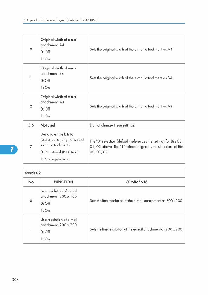
0
Original width of e-mailattachment: A4
0: Off
1: On
Sets the original width of the e-mail attachment as A4.
1
Original width of e-mailattachment: B4
0: Off
1: On
Sets the original width of the e-mail attachment as B4.
2
Original width of e-mailattachment: A3
0: Off
1: On
Sets the original width of the e-mail attachment as A3.
3-6 Not used Do not change these settings.
7
Designates the bits toreference for original size ofe-mail attachments
0: Registered (Bit 0 to 6)
1: No registration.
The "0" selection (default) references the settings for Bits 00,01, 02 above. The "1" selection ignores the selections of Bits00, 01, 02.
Switch 02
No FUNCTION COMMENTS
0
Line resolution of e-mailattachment: 200 x 100
0: Off
1: On
Sets the line resolution of the e-mail attachment as 200 x100.
1
Line resolution of e-mailattachment: 200 x 200
0: Off
1: On
Sets the line resolution of the e-mail attachment as 200 x 200.
7. Appendix: Fax Service Program (Only For D068/D069)
308
7

2
Line resolution of e-mailattachment: 200 x 400
0: Off
1: On
Sets the line resolution of the e-mail attachment as 200 x 400.
3 Not used Do not change these settings.
4
Line resolution of e-mailattachment: 400 x 400
0: Off
1: On
Sets the line resolution of the e-mail attachment as 400 x 400.
5-6 Not used Do not change these settings.
7
Designates the bits toreference for original size ofe-mail attachments
0: Registered (Bit 0 to 6)
1: No registration.
The "0" selection (default) references the settings for Bits 00,01, 02, 04 above. The "1" selection ignores the selections ofBits 00, 01, 02, 04.
Switch 03 - Not used (do not change the settings)
Switch 04
No FUNCTION COMMENTS
0
Full mode address selection
0: Full mode address
1: No full mode (simple mode)
If the other ends have the addresses, which have the full modefunction flag ("0"), this machine determines them as full modestandard machines.
• This machine attaches the "demand of receptionconfirmation" to a message when transmitting.
• This machine updates the reception capability to theaddress book when receiving.
1-7 Not used Do not change these settings.
Switch 05
No FUNCTION COMMENTS
Dedicated Transmission Parameters
309
7

0
Directr transmission selectionto SMTP server
0: ON
1: OFF
Allows or does not allow the direct transmission to SMTPserver.
1-7 Not used Do not change these settings.
Switch 06 - Not used (do not change the settings)
Switch 07 - Not used (do not change the settings)
Switch 08 - Not used (do not change the settings)
Switch 09 - Not used (do not change the settings)
7. Appendix: Fax Service Program (Only For D068/D069)
310
7

Service RAM AddressesThis section is used only for F/SPF models (D068/D069).
• Do not change the settings which are marked as “Not used” or “Read only.”
680000(H) - Machine code
680001 to 680004(H) - ROM version (Read only)
680001(H) - Revision number (BCD)
680002(H) - Year (BCD)
680003(H) - Month (BCD)
680004(H) - Day (BCD)
680005(H) - Machine code 2 (check ram2)
680006 to 680015(H) - Machine’s serial number (16 digits - ASCII)
680016(H) - Language code
Bit0: Japanese, Bit1: English (UK), Bit2: English (USA), Bit3: French,
Bit4: German, Bit5: Spanish, Bit6: Italian, Bit7: Dutch, Bit8: Swedish,
Bit9: Norwegian, Bit10: Danish, Bit11: Finnish, Bit12: Czech,
Bit13: Hungarian, Bit14: Polish, Bit15: Portuguese, Bit16: Russian,
Bit17: Traditional Chinese, Bit18: Simplified Chinese, Bit19: Hangul
680018(H) - Total program checksum (low)
680019(H) - Total program checksum (high)
680020 to 68003F(H) - System bit switches
680050 to 68005F(H) - Printer bit switches
680060 to 68007F(H) - Communication bit switches
680080 to 68008F(H) - G3 bit switches
680090 to 68009F(H) - G3-2 bit switches: Not used
6800A0 to 6800AF(H) - G3-3 bit switches: Not used
6800D0(H) - User parameter switch 00 (SWUER_00) : Not used
6800D1(H) - User parameter switch 01 (SWUSR_01) : Not used
6800D2(H) - User parameter switch 02 (SWUSR_02)
Bit 0: Forwarding mark printing on forwarded messages
0: OFF, 1: ON (Print)
Bit 1: Center mark printing on received copies
Service RAM Addresses
311
7

(This switch is not printed on the user parameter list.)
0: OFF, 1: ON (Print)
Bit 2: Reception time printing
(This switch is not printed on the user parameter list.)
0: OFF, 1: ON (Print)
Bit 3: TSI print on received messages 0: OFF, 1: ON (Print)
Bit 4: Checkered mark printing
(This switch is not printed on the user parameter list.)
0: OFF, 1: ON (Print)
Bit 5: Not used
Bit 6: Not used
Bit 7: Not used
6800D3(H) - User parameter switch 03 (SWUSR_03: Automatic report printout)
Bit 0: Transmission result report (memory transmissions) 0: Off, 1: On
Bit 1: Not used
Bit 2: Memory storage report 0: Off, 1: On
Bit 3: Polling reserve report (polling reception) 0: Off, 1: On
Bit 4: Polling result report (polling reception) 0: Off, 1: On
Bit 5: Transmission result report (immediate transmissions) 0: Off, 1: On
Bit 6: Not used
Bit 7: Journal 0: Off, 1: On
6800D4(H) - User parameter switch 04 (SWUSR_04: Automatic report printout)
Bit 0: Not used
Bit 1: Automatic communication failure report and transfer result report output 0: Off, 1: On
Bits 2 to 3: Not used
Bit 4: Indicates the parties 0: Not indicated, 1: Indicated
Bit 5: Include sender’s name on reports 0: Off, 1: On
Bit 6: Not used
Bit 7: Inclusion of a sample image on reports 0: Off, 1: On
6800D5(H) - User parameter switch 05 (SWUSR_05)
Bit 0: Substitute reception when the base copier is in an SC condition
0: Enabled, 1: Disabled
7. Appendix: Fax Service Program (Only For D068/D069)
312
7

Bits 1 and 2: Condition for substitute rx when the machine cannot print messages (Paper end, toner end,jam, and during night mode)
Bit 2: 0, Bit 1: 0 = The machine receives all the fax messages.
Bit 2: 0, Bit 1: 1 = The machine receives the fax messages with RTI or CSI.
Bit 2: 1, Bit 1: 0 = The machine receives the fax messages with the same ID code.
Bit 2: 1, Bit 1: 1 = The machine does not receive anything.
Bits 3 and 4: Not used
Bit 5: Just size printing 0: Off, 1: On
Bit 6: Not used
Bit 7: Add paper display when a cassette is empty 0: Off, 1: On
6800D6(H) - User parameter switch 06 (SWUSR_06): Not used
6800D7(H) - User parameter switch 07 (SWUSR_07)
Bits 0 and 1: Not used
Bit 2: Parallel memory transmission 0: Off, 1: On
Bits 3 to 7: Not used
6800D8(H) - User parameter switch 08 (SWUSR_08)
Bits 0 and 1: Not used.
Bit 2: Authorized reception
0: Only faxes from senders whose RTIs/CSIs are specified for this feature are accepted.
1: Only faxes from senders whose RTIs/CSIs are not specified for this feature are accepted.
Bits 3 to 7: Not used.
6800D9(H) - User parameter switch 09 (SWUSR_09): Not used
6800DA(H) - User parameter switch 10 (SWUSR_0A)
Bits 0 to 2: Not used
Bit 3: Page reduction 0: Off, 1: On
Bits 4 and 5: Not used
Bit 6: Use both e-mail notification and printed reports to confirm the transmission results 0: Off, 1: On
Bit 7: Not used
6800DB(H) - User parameter switch 11 (SWUSR_0B)
Bits 0 and 1: Not used
Bit 2: White original detection 0: Off, 1: On (alarm and alert message on the LCD)
Bits 3 and 4: Not used
Bit 6: Printout of messages received while acting as a forwarding station 0: Off, 1: On
Service RAM Addresses
313
7

Bit 7: Not used
6800DC(H) - User parameter switch 12 (SWUSR_0C): Not used
6800DD(H) - User parameter switch 13 (SWUSR_0D): Not used
6800DE(H) - User parameter switch 14 (SWUSR_0E)
Bit 0: Message printout while the machine is in Night Printing mode 0: On, 1: Off
Bit 1: Maximum document length detection 0: Double letter, 1: Longer than double-letter (well log) – upto 1,200 mm
Bit 2: Not used
Bit 3: Fax mode settings, such as resolution, before a mode key (Copy/Fax/Printer/Scanner) is pressed0: Not cleared, 1: Cleared
Bits 4 to 7: Not used
6800DF(H) - User parameter switch 15 (SWUSR_0F)
(This switch is not printed on the user parameter list.)
Bits 0, 1 and 2: Cassette for fax printout
Bit 2: 0, Bit 1: 0, Bit 0: 1 = 1st paper feed station
Bit 2: 0, Bit 1: 1, Bit 0: 0 = 2nd paper feed station
Bit 2: 0, Bit 1: 1, Bit 0: 1 = 3rd paper feed station
Bit 2: 1, Bit 1: 0, Bit 0: 0 = 4th paper feed station
Bit 2: 1, Bit 1: 0, Bit 0: 1 = LCT
Other settings Not used
Bits 3 and 4: Not used
Bit 5: Using the cassette specified by bits 0, 1 and 2 above only 0: On, 1: Off
Bits 6 and 7: Not used
6800E0(H) – User parameter switch 16 (SWUSR_10)
(This switch is not printed on the user parameter list.)
Bits 0 and 1: Not used
Bit 2: Paper size selection priority for an A4 size fax message when A4/LT size paper is not available. 0:A3 has priority, 1: B4 has priority
Bits 3 to 7: Not used
6800E1(H) – User parameter switch 17 (SWUSR_11)
Bits 0 and 1: Not used
Bit 2: Inclusion of the “Add” button when a sequence of Quick/Speed dials is selected for broadcasting0: Not needed, 1: Needed
Bit 3: Not used
7. Appendix: Fax Service Program (Only For D068/D069)
314
7

Bit 4: Reconfirmation of an address before press “Start” key. 0: Not displayed, 1: Displayed
Bits 5 and 6: Not used
Bit 7: Press “Start” key without an original when using the on hook dial or the external telephone,
0: displays “Cannot detect original size”. 1: Receives fax messages.
6800E2(H) - User parameter switch 18 (SWUSR_12)
Bit 0: TTI date 0: Off, 1: On
Bit 1: TTI sender 0: Off, 1: On
Bit 2: TTI file number 0: Off, 1: On
Bit 3: TTI page number 0: Off, 1: On
Bits 4 to 7: Not used
6800E3(H) - User parameter switch 19 (SWUSR_13)
Bit 0: Not used
Bit 1: Journal format
0: The Journal is separated into transmissions and receptions
1: The Journal is separated into G3-1, G3-2, and G3-3 communications
Bit 2: Not used
Bit 3: 90° image rotation during B5 portrait Tx (This switch is not printed on the user parameter list.) 0: Off,1: On
Bit 4: Reduction of sample images on reports to 50% in the main scan and sub-scan directions. (This switchis not printed on the user parameter list.) 0: Technician adjustment (printer switch 0E bits 3 and 4), 1: 50%reductionBit 5: Use of A5 size paper for reports (This switch is not printed on the user parameter list.) 0: Off, 1: On
Bits 6 and 7: Not used
6800E4(H) - User parameter switch 20 (SWUSR_14)
Bit 0: Automatic printing of the LAN fax result report 0: Off, 1: OnBit 1: Not used.
Bits 2 to 5: Store documents in memory which could not be printed from PC fax (LAN fax) driver
Bit 5 Bit 4 Bit 3 Bit 2 Setting
0 0 0 0 0 min.
0 0 0 1 1 min.
1 1 1 0 14 min.
Service RAM Addresses
315
7

1 1 1 1 15 min.
Bits 6 and 7: Not used.
6800E5(H) - User parameter switch 21 (SWUSR_15)
Bit 0: Print results of sending reception notice request message 0: Disabled (print only when error occurs),1: Enabled
Bit 1: Respond to e-mail reception acknowledgment request 0: Disabled, 1: Enabled
Bit 2: Not used
Bit 3: File format for forwarded folders 0: TIFF, 1:PDF
Bit 4: Transmit Journal by E-mail 0: Disabled, 1: Enabled
Bit 5: Not used
Bit 6: Network error display 0: Displayed, 1: Not displayed
Bit 7: Transmit error mail notification 0: Enabled, 1: Disabled
6800E6(H) - User parameter switch 22 (SWUSR_16)
(This switch is not printed on the user parameter list.)
Bit 0: Dial tone detection (PSTN 1) 0: Disabled, 1: Enabled
Bits 1 to 3: Not used
Bits 4 to 7: Setting the number of times of address input using numeric key 0: Off, 1 to 15: On
6800E7(H) - User parameter switch 23 (SWUSR_17): Not used
6800E8(H) - User parameter switch 24 (SWUSR_18): Not used
6800E9(H) - User parameter switch 25 (SWUSR_19)
Bits 0 to 3: Not used
Bit 4: RDS operation 0: Not acceptable, 1: Acceptable for the limit specified by system switch 03
• This bit is only effective when RDS operation can be selected by the user(see system switch 02).
Bits 5 to 7: Not used
6800EA(H) and 6800EB(H) - User parameter switches 26 and 27 (SWUSR_1A and 1B): Not used
6800EC(H) - User parameter switch 28 (SWUSR_1C)
- Ringing times setting in the TEL line priority mode: 00 to 99 (BCD)
6800ED(H) - User parameter switch 29 (SWUSR_1D): Not used
6800EE(H) and 6800EF(H) - User parameter switches 30 and 31 (SWUSR_1E and 1F): Not used
6800F0(H) - User parameter switch 32 (SWUSR_20)
Bit 0: Quotation priority for a destination when there is no destination of the specified type
7. Appendix: Fax Service Program (Only For D068/D069)
316
7

0: Paper output priority = Priority order: 1. IP-fax destination, 2. Fax Number, 3. E-mail address, 4. Folder
1: Electric putout order = Priority order: 1. E-mail address, 2. Folder, 3. IP-fax destination, 4. Fax number
Bits 1 to 7: Not used
6800F1(H) - User parameter switch 33 (SWUSR_21): Not used
6800F2(H) - User parameter switch 34 (SWUSR_22)
Bit 0: Gatekeeper server used with IP-Fax 0: Disabled, 1: Enabled
Bit 1: SIP server used with IP-Fax 0: Disabled, 1: Enabled
Bits 2 to 7: Not used
680100 to 68010F(H) - G4 Parameter Switches – Not used
680110 to 68012F(H) - G4 Internal Switches – Not used
680130 to 68016F(H) - Service Switches (SCU) – Not used
680170 to 68017F(H) - IFAX Switches
680180 to 68018F(H) - IP-FAX Switches
680190 to 6801AF(H) - Service station’s fax number (SP3-101)
6801B0 to 6801B9(H) - Own fax PABX extension number
6801BA to 6801C3(H) - Own fax number (PSTN) – Not used
6801C4 to 6801D7(H) - Own fax number (ISDN G4) – Not used
6801D8 to 6801E3(H) - The first subscriber number (ISDN G3) – Not used
6801E4 to 6801EF(H) - The second subscriber number (ISDN G3) – Not used
6801F0 to 6801FB(H) - The first subscriber number (ISDN G4) – Not used
6801FC to 680207(H) - The second subscriber number (ISDN G4) – Not used
680208 to 68021B(H) - PSTN-1 RTI (Max. 20 characters - ASCII) - See the following note.
68021C to 68022F(H) - PSTN-2 RTI (Max. 20 characters - ASCII) - Not used
680230 to 680246(H) - PSTN-3 RTI (Max. 20 characters - ASCII) - Not used
680247 to 680286(H) - TTI 1 (Max. 64 characters - ASCII) - See the following note.
680287 to 6802C6(H) - TTI 2 (Max. 64 characters - ASCII) - Not used
6802C7 to 680306(H) - TTI 3 (Max. 64 characters - ASCII) - Not used
680307 to 68031A(H) - PSTN-1 CSI (Max. 20 characters - ASCII)
68031B to 68032E(H) - PSTN-2 CSI (Max.20 characters - ASCII) - Not used
68032F to 680342(H) - PSTN-3 CSI (Max.20 characters - ASCII) - Not used
680343(H) - Number of PSTN-1 CSI characters (Hex)
680344(H) - Number of PSTN-2 CSI characters (Hex) - Not used
680345(H) Number of PSTN-3 CSI characters (Hex) - Not used
Service RAM Addresses
317
7

• If the number of characters is less than the maximum (20 for RTI, 64 for TTI), add a stop code (00[H])after the last character.
680370(H) ID for transmission and reception (Read only – Do not change the settings)
680374 to 680375(H) - Envelopment ID for the envelopment reception (BCD)
680380 to 680387(H) - Last power off time (Read only)
680380(H) - 01(H) - 24-hour clock, 00(H) - 12-hour clock (AM), 02(H) - 12-hour clock (PM)
680381(H) - Year (BCD)
680382(H) - Month (BCD)
680383(H) - Day (BCD)
680384(H) – Hour
680385(H) – Minute
680386(H) – Second
680387(H) - 00: Monday, 01: Tuesday, 02: Wednesday, /// , 06: Sunday
680394(H) - Optional equipment – Not used
680395(H) - Optional equipment (Read only – Do not change the settings)
Bits 0 to 3: Not used
Bit 4: G3-2 0: Not installed, 1: Installed
Bit 5: G3-3 0: Not installed, 1: Installed
Bit 6 and 7: Not used
680401 to 68040D – Not used
680410(H) - G3-1 Modem ROM version (Read only)
680412(H) - G3-2 Modem ROM version – Not used
680414(H) - G3-3 Modem ROM version – Not used
680420(H) - Number of multiple sets print (Read only)
680476(H) - Time for economy transmission – Not used
68048C(H) - Dial in (BCD)
680492(H) - Transmission monitor volume 00 - 07(H)
680493(H) - Reception monitor volume 00 - 07(H)
680494(H) - On-hook monitor volume 00 - 07(H)
680495(H) - Dialing monitor volume 00 - 07(H)
680496(H) - Buzzer volume 00 - 07(H)
680497(H) - Beeper volume 00 - 07(H)
7. Appendix: Fax Service Program (Only For D068/D069)
318
7

6804A8(H) - Machine code (Check ram 4)
6804D2(H) - Serial number (Max. 8 characters ASCII)
685E6C to 685E6F(H) - Transmission counter (HEX)
685E70 to 685E73(H) - Reception counter (HEX)
685EDC to 685EDF(H) - E-mail transmission counter (HEX)
685EE0 to 685EE3(H) - E-mail reception counter (HEX)
688E8E to 68918D(H) - SIP server address (Read only)
688E8E(H) - Proxy server - Main (Max. 128 characters - ASCII)
688F0E(H) - Proxy server - Sub (Max. 128 characters - ASCII)
688F8E(H) - Redirect server - Main (Max. 128 characters - ASCII)
68900E(H) - Redirect server - Sub (Max. 128 characters - ASCII)
68908E(H) - Registrar server - Main (Max. 128 characters - ASCII)
68910E(H) - Registrar server - Sub (Max. 128 characters - ASCII)
68918E(H) - Gatekeeper server address - Main (Max. 128 characters - ASCII)
68920E(H) - Gatekeeper server address - Sub (Max. 128 characters - ASCII)
68928E(H) - Arias Number (Max. 128 characters - ASCII)
68930E(H) - SIP user name (Max. 128 characters - ASCII)
68938E(H) - SIP authentication password (Max. 128 characters - ASCII)
68938E(H) - SIP digest authentication password (Max. 128 characters - ASCII)
68940E(H) - Gateway address information (Max. 7100 characters - ASCII)
68AFCA(H) - Stand-by port number for H.232 connection
68AFCCH) - Stand-by port number for SIP connection
68AFCE(H) - RAS port number
68AFD0(H) - Gatekeeper port number
68AFD2(H) - Port number of data waiting for T.38
68AFD4(H) - Port number of SIP server
68AFD6(H) - Priority for SIP and H.323 0: H.323, 1: SIP
68AFD7(H) - SIP function 0: Disabled, 1: Enabled
68AFD8(H) - H.323 function 0: Disabled, 1: Enabled
68AFD9(H) - SIP digest authentication function 0: Disabled, 1: Enabled
68AFDA(H) - IP-Fax backup data 00 - 600 (H)
69ECBE(H) - 69ECDE(H) - Dial tone detection parameter (Max. 11 x 3 lines)
This initializes following order. [0x04, 0x40, 0x03, 0x60, 0x64, 0xf4, 0x01,0x64, 0x04, 0xc8, 0x00]
Service RAM Addresses
319
7

7. Appendix: Fax Service Program (Only For D068/D069)
320
7