model pj regulator/converter - impco … model pj regulator converter. ... coverter to ctr of vapor...
TRANSCRIPT
August, 2010 IMPCO Technologies Inc. PPI-112 REV. B 3030 South Susan St. Page 1 of 13 Santa Ana, CA 92704
www.impcotechnologies.com
MODEL PJ REGULATOR/CONVERTER
REPAIR KIT INSTRUCTIONS
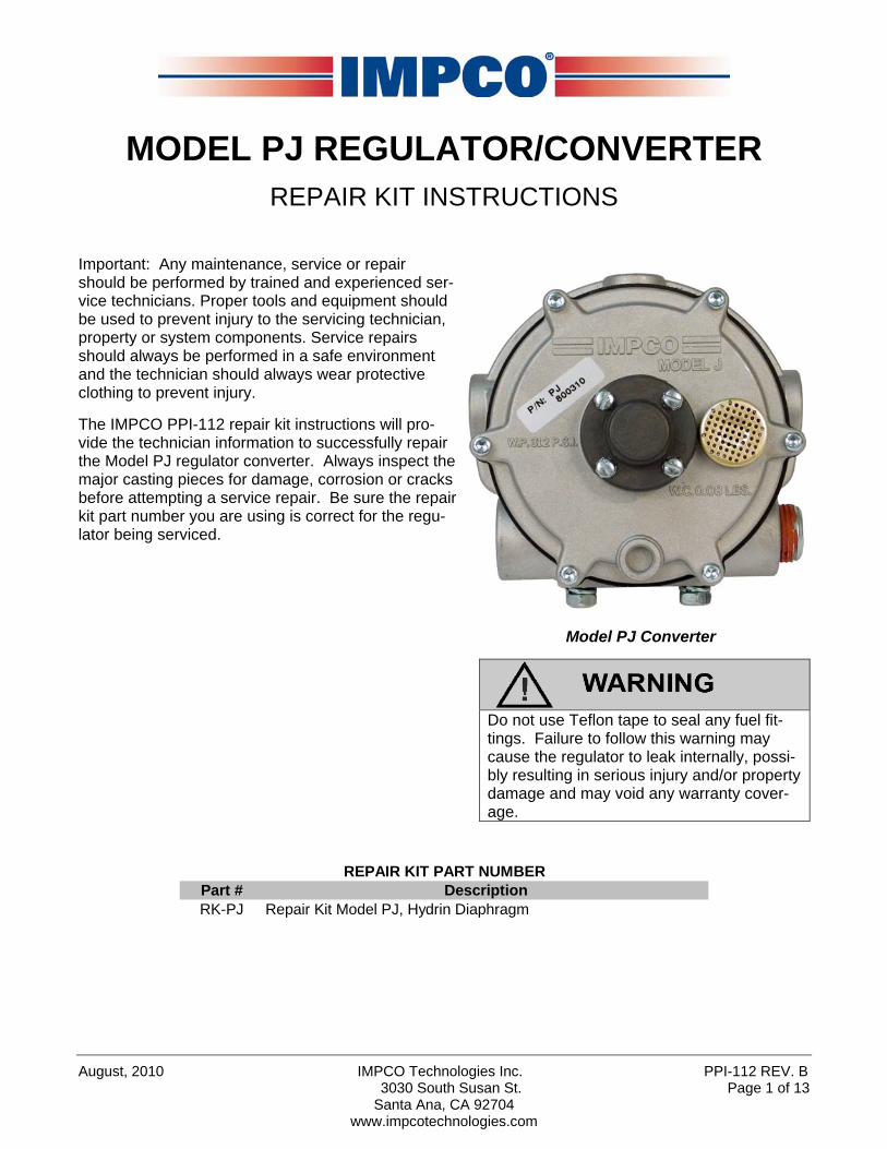
Important: Any maintenance, service or repair should be performed by trained and experienced ser-vice technicians. Proper tools and equipment should be used to prevent injury to the servicing technician, property or system components. Service repairs should always be performed in a safe environment and the technician should always wear protective clothing to prevent injury.
The IMPCO PPI-112 repair kit instructions will pro-vide the technician information to successfully repair the Model PJ regulator converter. Always inspect the major casting pieces for damage, corrosion or cracks before attempting a service repair. Be sure the repair kit part number you are using is correct for the regu-lator being serviced.
Model PJ Converter
Do not use Teflon tape to seal any fuel fit-tings. Failure to follow this warning may cause the regulator to leak internally, possi-bly resulting in serious injury and/or property damage and may void any warranty cover-age.
Part # DescriptionRK-PJ Repair Kit Model PJ, Hydrin Diaphragm
REPAIR KIT PART NUMBER

PPI-112 REV. B IMPCO Technologies Inc. August, 2010 Page 2 of 13 3030 South Susan St.
Santa Ana, CA 92704 www.impcotechnologies.com
MODEL PJ REGULATOR/CONVERTER
A B C D E F G H J K
OVERALL HEIGHT
OVERALL DEPTH
OVERALL WIDTH
BACK OF COVERTER TO CTR OF VAPOR FUEL OUTLET
BACK OF CONVETER TO CTR. OF
WATER OUTLET
MOUNTING HOLES CTR.
TO CTR.
COOLANT INLET AND
OUTLET (NPT)
LIQUID FUEL INLET (NPT)
PRIMARY TEST PORT (NPT)
VAPOR FUEL
OUTLET (NPT)
109.98mm (4.33")
80.00mm (3.15")
118mm (4.63")
37.8mm (1.49")26.42mm
(1.04")41.3mm (1.63")
3/8" 1/4" 1/8" 1/2"
MODEL SECONDARY DIAPHRAM OUTLET PRESSUREPJ AD1-26-2 (Hydrin) Nominal +5.0" w.c.
August, 2010 IMPCO Technologies Inc. PPI-112 REV. B 3030 South Susan St. Page 3 of 13 Santa Ana, CA 92704
www.impcotechnologies.com
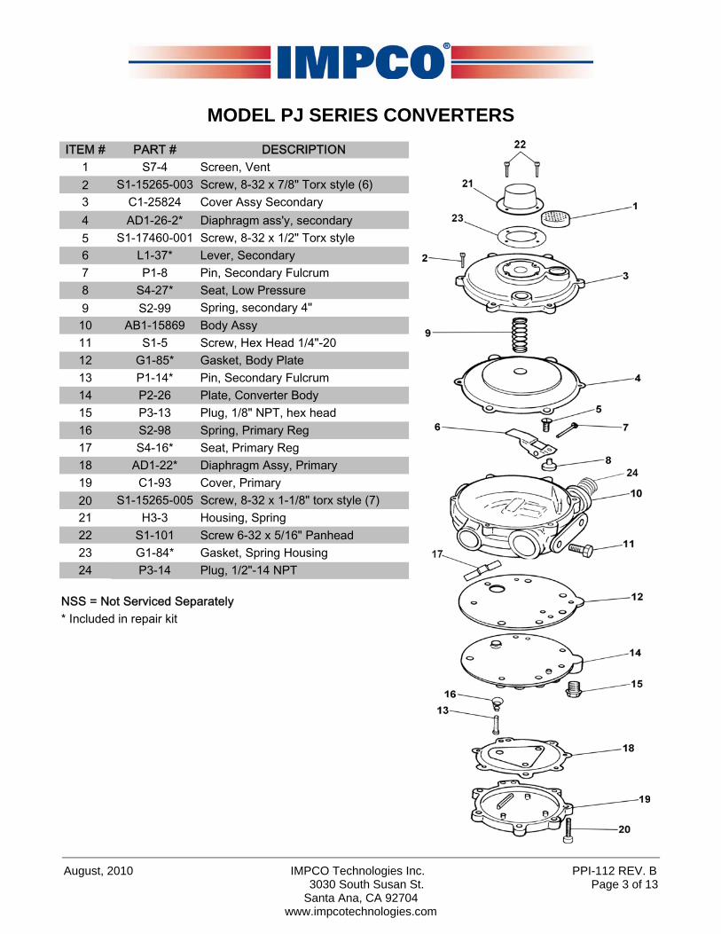
MODEL PJ SERIES CONVERTERS ITEM # PART # DESCRIPTION
1 S7-4 Screen, Vent2 S1-15265-003 Screw, 8-32 x 7/8" Torx style (6)3 C1-25824 Cover Assy Secondary4 AD1-26-2* Diaphragm ass'y, secondary5 S1-17460-001 Screw, 8-32 x 1/2" Torx style6 L1-37* Lever, Secondary7 P1-8 Pin, Secondary Fulcrum8 S4-27* Seat, Low Pressure9 S2-99 Spring, secondary 4"10 AB1-15869 Body Assy11 S1-5 Screw, Hex Head 1/4"-2012 G1-85* Gasket, Body Plate13 P1-14* Pin, Secondary Fulcrum14 P2-26 Plate, Converter Body15 P3-13 Plug, 1/8" NPT, hex head16 S2-98 Spring, Primary Reg17 S4-16* Seat, Primary Reg18 AD1-22* Diaphragm Assy, Primary19 C1-93 Cover, Primary20 S1-15265-005 Screw, 8-32 x 1-1/8" torx style (7)21 H3-3 Housing, Spring22 S1-101 Screw 6-32 x 5/16" Panhead23 G1-84* Gasket, Spring Housing24 P3-14 Plug, 1/2"-14 NPT
NSS = Not Serviced Separately* Included in repair kit

PPI-112 REV. B IMPCO Technologies Inc. August, 2010 Page 4 of 13 3030 South Susan St.
Santa Ana, CA 92704 www.impcotechnologies.com
REBUILD INSTRUCTIONS
1. Under normal conditions, installation of a complete Model PJ Repair Kit should be necessary only at the time of a major engine overhaul or when the converter has been out of service for an extended period of time. Each kit includes the gaskets, diaphragms, and seats necessary for servicing.
2. Remove the 6 screws (2) from the secondary cover
assembly (3).
NOTE: Identify the type and location of screws re-moved (i.e. Torx) in all steps to ensure the same type and size screws are returned to the correct locations during reassembly.
3. Loosen the secondary cover (3) by tapping around the
circumference with a plastic screw driver handle or rubber mallet.
4. Remove the secondary cover (3) and secondary diaph-
ragm (4) as a unit. Note the secondary lever (6) pro-truding through the metal tab slot of the secondary di-aphragm. Slide the cover and diaphragm toward the gas inlet to free the lever from the slotted tab of the di-aphragm. Gently remove this assembly to prevent bending the lever. Remove diaphragm from cover and spring. The secondary spring (9) will be found be-tween the cover and diaphragm.

August, 2010 IMPCO Technologies Inc. PPI-112 REV. B 3030 South Susan St. Page 5 of 13 Santa Ana, CA 92704
www.impcotechnologies.com
5. Remove the four screws (22) securing the spring hous-ing (21).
6. Remove the spring housing (21) and gasket (23).
7. Remove screw (5), the secondary lever (6) and the ful-
crum pin (7) and set aside for the reassembly.
8. Turn the converter over. Remove the seven screws (20) and lift off the primary cover (19).
PPI-112 REV. B IMPCO Technologies Inc. August, 2010 Page 6 of 13 3030 South Susan St.
Santa Ana, CA 92704 www.impcotechnologies.com
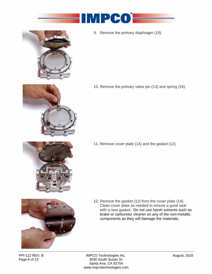
9. Remove the primary diaphragm (18).
10. Remove the primary valve pin (13) and spring (16).
11. Remove cover plate (14) and the gasket (12).
12. Remove the gasket (12) from the cover plate (14). Clean cover plate as needed to ensure a good seal with a new gasket. Do not use harsh solvents such as brake or carburetor cleaner on any of the non-metallic components as they will damage the materials.

August, 2010 IMPCO Technologies Inc. PPI-112 REV. B 3030 South Susan St. Page 7 of 13 Santa Ana, CA 92704
www.impcotechnologies.com
13. Remove the primary seat (17). Clean covers, body and metal parts as necessary with a safety solvent as needed and allow to dry prior to reassembly. Do not use harsh solvents such as brake or carburetor cleaner on any of the non-metallic components as they will damage the material.
14. Install new primary regulator seat (17).
15. Set new primary gasket, (12), from the kit on the con-verter cover plate (14). The gasket will only fit one way (screw hole spacing prevents improper orientation of the diaphragm). The primary pressure hole in the gasket must line up with the hole in the body cover plate.
16. Place the cover plate (14) and gasket (12) on the con-
verter body and align the cover screw holes.

PPI-112 REV. B IMPCO Technologies Inc. August, 2010 Page 8 of 13 3030 South Susan St.
Santa Ana, CA 92704 www.impcotechnologies.com
17. Insert the new primary valve pin (13) through the spring (16) and insert into the cover (14) with the larger di-ameter end of the spring resting against the plate.
18. Set the primary diaphragm (18) in place on the conver-
ter body cover plate (14). Line up the screw holes to the cover plate.
19. Carefully place the primary cover (19) over the diaph-
ragm (18). Hand-thread the screws (20) through the cover and cover plate into the converter body.
20. Tighten the screws (20) to 22-28 in-lb. (2.5-3.2 N•m) in a criss-cross pattern.
August, 2010 IMPCO Technologies Inc. PPI-112 REV. B 3030 South Susan St. Page 9 of 13 Santa Ana, CA 92704
www.impcotechnologies.com
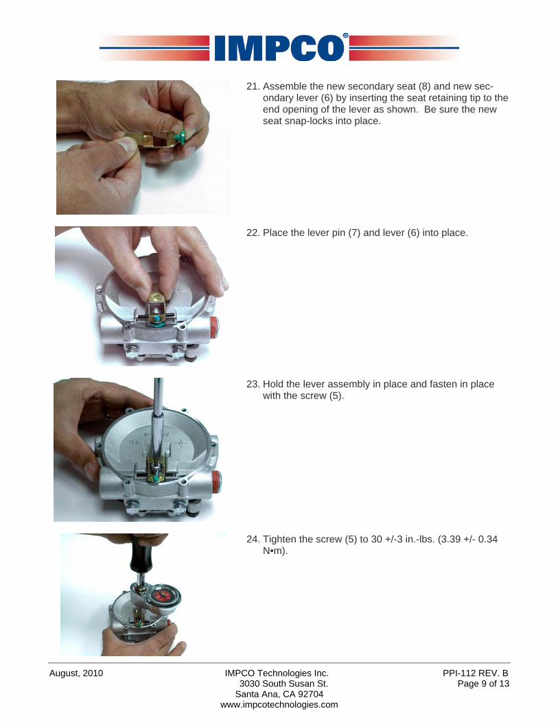
21. Assemble the new secondary seat (8) and new sec-ondary lever (6) by inserting the seat retaining tip to the end opening of the lever as shown. Be sure the new seat snap-locks into place.
22. Place the lever pin (7) and lever (6) into place.
23. Hold the lever assembly in place and fasten in place
with the screw (5).
24. Tighten the screw (5) to 30 +/-3 in.-lbs. (3.39 +/- 0.34
N•m).
PPI-112 REV. B IMPCO Technologies Inc. August, 2010 Page 10 of 13 3030 South Susan St.
Santa Ana, CA 92704 www.impcotechnologies.com
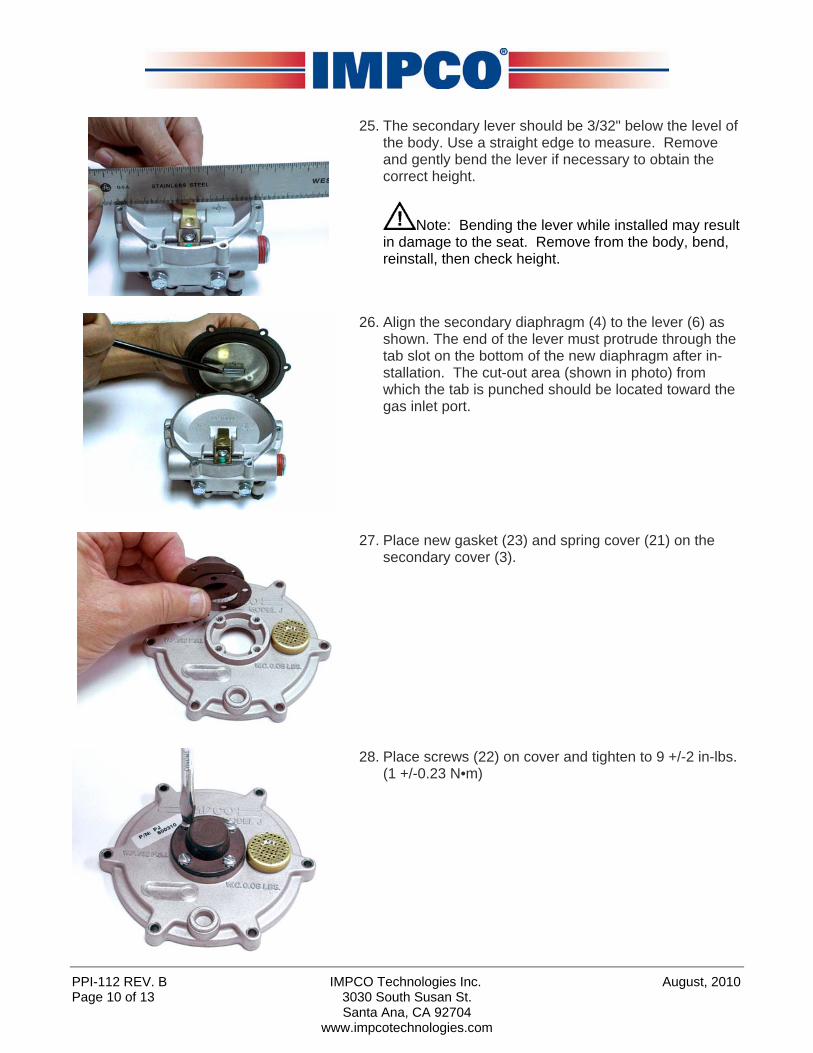
25. The secondary lever should be 3/32" below the level of the body. Use a straight edge to measure. Remove and gently bend the lever if necessary to obtain the correct height.
Note: Bending the lever while installed may result in damage to the seat. Remove from the body, bend, reinstall, then check height.
26. Align the secondary diaphragm (4) to the lever (6) as
shown. The end of the lever must protrude through the tab slot on the bottom of the new diaphragm after in-stallation. The cut-out area (shown in photo) from which the tab is punched should be located toward the gas inlet port.
27. Place new gasket (23) and spring cover (21) on the secondary cover (3).
28. Place screws (22) on cover and tighten to 9 +/-2 in-lbs.
(1 +/-0.23 N•m)
August, 2010 IMPCO Technologies Inc. PPI-112 REV. B 3030 South Susan St. Page 11 of 13
Santa Ana, CA 92704 www.impcotechnologies.com
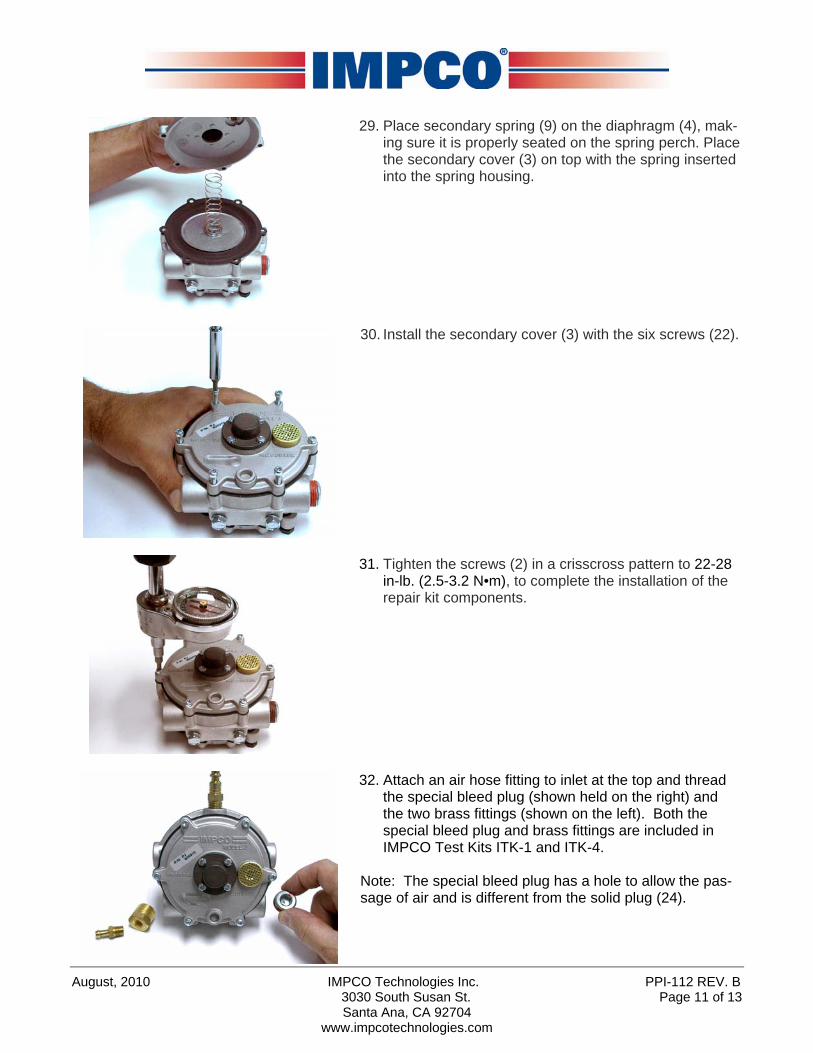
29. Place secondary spring (9) on the diaphragm (4), mak-ing sure it is properly seated on the spring perch. Place the secondary cover (3) on top with the spring inserted into the spring housing.
30. Install the secondary cover (3) with the six screws (22).
31. Tighten the screws (2) in a crisscross pattern to 22-28
in-lb. (2.5-3.2 N•m), to complete the installation of the repair kit components.
32. Attach an air hose fitting to inlet at the top and thread
the special bleed plug (shown held on the right) and the two brass fittings (shown on the left). Both the special bleed plug and brass fittings are included in IMPCO Test Kits ITK-1 and ITK-4.
Note: The special bleed plug has a hole to allow the pas-sage of air and is different from the solid plug (24).
PPI-112 REV. B IMPCO Technologies Inc. August, 2010 Page 12 of 13 3030 South Susan St.
Santa Ana, CA 92704 www.impcotechnologies.com
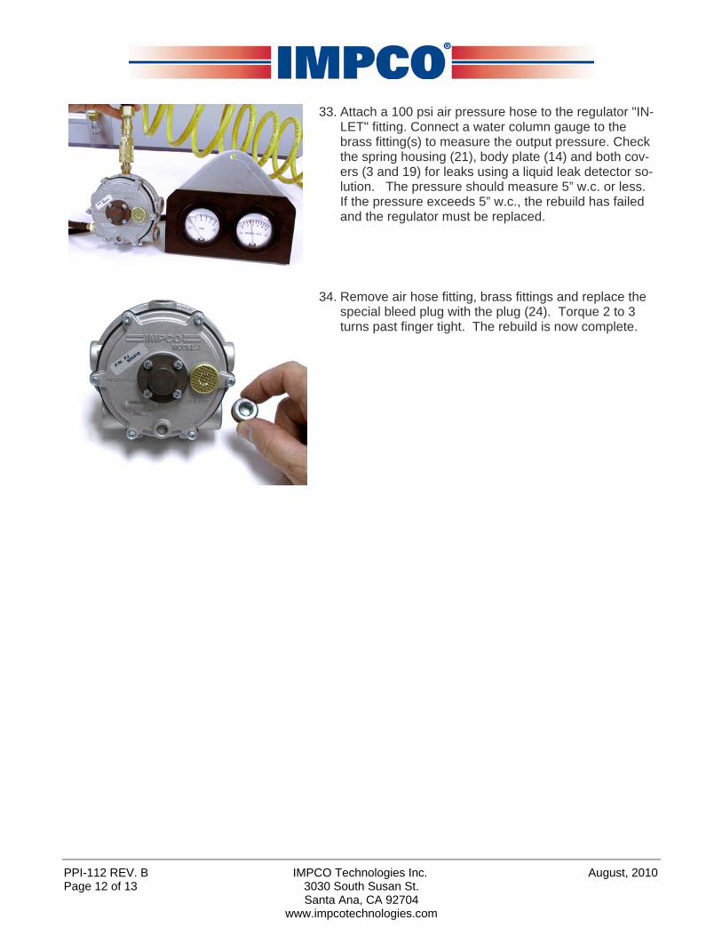
33. Attach a 100 psi air pressure hose to the regulator "IN-LET" fitting. Connect a water column gauge to the brass fitting(s) to measure the output pressure. Check the spring housing (21), body plate (14) and both cov-ers (3 and 19) for leaks using a liquid leak detector so-lution. The pressure should measure 5” w.c. or less. If the pressure exceeds 5” w.c., the rebuild has failed and the regulator must be replaced.
34. Remove air hose fitting, brass fittings and replace the special bleed plug with the plug (24). Torque 2 to 3 turns past finger tight. The rebuild is now complete.

August, 2010 IMPCO Technologies Inc. PPI-112 REV. B 3030 South Susan St. Page 13 of 13
Santa Ana, CA 92704 www.impcotechnologies.com
WARNING: IMPROPER INSTALLATION OR USE OF THIS PRODUCT MAY CAUSE
SERIOUS INJURY AND/OR PROPERTY DAMAGE.
SERVICE TECHNICIANS AND USERS SHOULD CAREFULLY READ AND ABIDE BY THE PROVISIONS SET FORTH IN NATIONAL FIRE PROTECTION ASSO-CIATION PAMPHLET #37 FOR STATIONARY ENGINES, #52 FOR CNG VEHICULAR FUEL SYSTEMS OR #58 FOR LPG SYSTEMS. INSTALLERS LPG INSTALLATIONS IN THE UNITED STATES MUST BE DONE IN ACCORDANCE WITH FEDERAL STATE OR LOCAL LAW, WHICHEVER IS APPLICABLE AND NATIONAL FIRE PROTECTION ASSOCIATION PAMPHLET #58, STANDARD FOR STORAGE AND HANDLING OF LIQUEFIED PETROLEUM GASES TO THE EXTENT THESE STANDARDS ARE NOT IN VIOLATION WITH FEDERAL, STATE OR LOCAL LAW. IN CANADA REFER TO CAN/CGA PROPANE INSTALLATION CODES. CNG INSTALLATIONS IN THE UNITED STATES MUST RE DONE IN ACCORDANCE WITH FEDERAL STATE OR LOCAL LAW AND NATIONAL FIRE PROTECTION AS-SOCIATION PAMPHLET #52, COMPRESSED NATURAL GAS (CNG) VEHICULAR FUEL SYSTEMS TO THE EXTENT THESE STANDARDS ARE NOT IN VIOLATION WITH FEDERAL, STATE OR LOCAL LAW. IN CANADA REFER TO CAN/CGA CNG INSTALLATION CODES. LPG AND/OR NATURAL GAS INSTALLATIONS ON STATIONARY ENGINES MUST RE DONE IN ACCORDANCE WITH FEDERAL, STATE OR LOCAL LAW AND NATIONAL FIRE PROTECTION AS-SOCIATION PAMPHLET #37, STATIONARY COMBUSTION ENGINES AND GAS TURBINE ENGINES, TO THE EXTENT THESE STANDARDS ARE NOT IN VIOLATION WITH FEDERAL, STATE OR LOCAL LAW. FAILURE TO ABIDE BY THE ABOVE WILL VOID ANY IMPCO WARRANTY ON THE PRODUCTS AND MAY CAUSE SERIES INJURY OR PROPERTY DAMAGE. DUE TO THE INHERENT DANGER OF GASEOUS FUELS THE IMPCO PRODUCTS SHOULD NOT BE INSTALLED OR USED BY PERSONS NOT KNOWLEDGEABLE OF THE HAZARDS ASSOCIATED WITH THE USE OF GASEOUS FUELS.