model paper for the proceedings of the 4th symposium on...
TRANSCRIPT
4th Symposium on Integrating CFD and Experiments in Aerodynamics 14-16 September 2009 von Karman Institute, Rhode-Saint-Genèse, Belgium
Integration of CFD and Experiments in the CUBRC LENS Shock Tunnel Facilities to Understand the Physics of Hypersonic and Hypervelocity Flows Matthew MacLean Timothy Wadhams Michael Holden CUBRC 4455 Genesee St. Buffalo, NY 14225 USA [email protected] Graham Candler Ioannis Nompelis University of Minnesota, Aerospace & Engineering Mechanics Dept. 107 Akerman Hall 110 Union St. SE Minneapolis, MN 55455-0153 USA Abstract The integration of experimental measurements and computational fluid dynamics in hypersonic and hypervelocity flows has been examined as it has been implemented at CUBRC for the past several years. Techniques of integration have been demonstrated through four primary examples covering the thermochemical interaction and catalytic heating augmentation on blunt bodies, laminar shock interaction on the double cone, transition and turbulent heating and turbulent shock interaction on the HIFiRE-1 test vehicle, and unsteady inlet starting and mode switching on a planar turbine/ramjet inlet. Several key lessons learned have been summarized based on the experiences in these and other programs.
Key words: CUBRC, LENS, shock tunnel, hypersonic, hypervelocity, CFD
1

4th Symposium on Integrating CFD and Experiments in Aerodynamics 14-16 September 2009 von Karman Institute, Rhode-Saint-Genèse, Belgium
Introduction
The study of hypersonic and hypervelocity flows requires the interrogation of many aspects of fundamental physical molecular and gasdynamic processes that can only effectively be performed by integrating the best quality numerical predictions and experiments. Test programs in the LENS facilities are completed by employing CFD solutions in real-time with each experiment both to plan the test article design, instrumentation, and test conditions, and to diagnose and analyze the data immediately after each test to insure data quality and that the underlying physical processes are targeted in the experiment. A key feature of this experimental and numerical integration is the real-time feedback to the experiment during and immediately after each run to help plan subsequent runs before the test program is concluded.
Several examples of recent experimental programs that have been directed and validated using CFD will be covered in detail in this paper with emphasis on the lessons learned and key insights gained into the physical phenomena through the integration of CFD and experiment. The ongoing work on the double cone is one of the best examples of integration, but our work also includes blunt body shapes like the Apollo and MSL heat shields where the physics of thermochemical non-equilibrium have been found to be key physical processes driving the shocklayer character and the surface heating and pressure. The HIFiRE-1 flight experiment has been used as an example of the integration of CFD and experiment to study the physics of transition and turbulent shock interaction where several critical vehicle design choices were made by employing the CFD codes and verifying the results obtained in the LENS facility. Finally, the need to employ CFD in the study of transient phenomena such as inlet unstart and mode switching is briefly highlighted.
Overview of CUBRC Experimental Facilities
Currently, CUBRC operates the 48” reflected shock tunnel, the LENS-I and LENS-II reflected shock tunnels [1], and the LENS-XX expansion tunnel [2] shown in Fig 1. The reflected shock tunnel uses incident and reflected shocks to cleanly heat and pressurize a stagnant test gas to high enthalpy levels. This test gas may then be expanded through a converging-diverging nozzle in a manner similar to a blowdown facility to produce a hypervelocity test flow. Expansion tunnels like LENS-XX also operate as short duration facilities, but an expansion tunnel produces a high enthalpy flow by adding kinetic energy directly to the flow by expanding through an accelerant gas. Because the flow is never stagnated, the expansion tunnel produces a quiescent freestream state that minimizes the thermal and
(c) LENS-XX (a) LENS-I (b) LENS-II
Figure 1. LENS Facilities at CUBRC
Figure 2. Velocity-Altitude Duplication Capabilities of CUBRC LENS
Facilities
2

4th Symposium on Integrating CFD and Experiments in Aerodynamics 14-16 September 2009 von Karman Institute, Rhode-Saint-Genèse, Belgium
chemical non-equilibrium that occurs in the freestream of reflected shock tunnels at very high enthalpies (>5MJ/kg). CUBRC employs both reflected shock and expansion tunnels to provide a wide range of supersonic, hypersonic, and hypervelocity test capabilities, which are summarized in Fig 2.
The LENS reflected shock-tunnel facilities were developed primarily to study the full-scale, hypervelocity flow physics of interceptors and air-breathing engine configurations. The scale and flow duplication capabilities of LENS are such that these vehicles can be studied at their full scale, inclusive of effects such as transition to turbulence, turbulent mixing from cross-flow jets and thrusters, duplicated flow chemistry, and other effects that are difficult or impossible to simulate at cold-flow or sub-scale conditions. The reflected shock-tunnel facilities have been validated with tests of measurements by comparing directly to numerical predictions, including recent work with tunable laser-diode diagnostics. Additionally, the facilities have been used to perform studies of fundamental flow phenomena like the double cone with success and to solve practical flight problems on vehicles like the Shuttle STS vehicle.
Overview of CUBRC Computational Tools and Numerical Methods
All ground test studies in the LENS facilities are extensively calibrated and validated with numerical tools. The primary CFD tool used is the DPLR code provided by NASA Ames Research Center. DPLR is a multi-block, structured, finite-volume code that solves the reacting Navier-Stokes equations including finite rate chemistry and finite rate vibrational non-equilibrium effects. This code is based on the data-parallel line relaxation method [3] and implements a modified (low dissipation) Steger-Warming flux splitting approach [4] for the convection terms and central differencing for the diffusion terms. Finite rate vibrational relaxation is modeled via a simple harmonic oscillator vibrational degree of freedom [5] using the Landau-Teller model [6]. Vibrational energy relaxation rates are computed by default from the semi-empirical expression due to Millikan and White [7], but rates from the work of Camac [8] and Park, et al [9] are substituted for specific collisions where experimental data exists. Vibration-dissociation coupling is currently modeled using the T-Tv approach of Park [10] or with some preliminary implementation of CVDV coupling [11]. Transport properties are appropriately modeled in DPLR for high enthalpy flow [12],[13] using the binary collision-integral based mixing rules from Gupta, et al [14]. Diffusion coefficients are modeled using the self-consistent effective binary diffusion (SCEBD) method [15]. Turbulence models available in the DPLR code currently include the Baldwin-Lomax 0-equation model [16], the Spalart-Allmaras model 1-equation model [17], and the Shear Stress Transport (SST) 2-equation model [18] each with corrections for compressibility effects [19],[20]. Recent relevant capabilities of the DPLR code involve automated grid adaptation to improve solution quality [21].
A specialized code has been developed by Candler [22] to compute the nozzle flowfield for a high-pressure, high-enthalpy ground test facility. This code shares much of its heritage with the NASA Ames DPLR code (described above) since it employs the same flux splitting and time integration treatments. The nozzle code has been streamlined by hardwiring parts of the code to solve for a single-block, axisymmetric nozzle with fixed boundary conditions. These modifications lead to a substantial decrease in required solution time and allow us to compute the nozzle flowfield in the same length of time that it requires to set-up and make a run in the LENS facilities (about 2 hours). The nozzle code employs the Spalart-Allmaras [17] one-equation turbulence model with the Catris and Aupoix compressibility correction [20]. This turbulence formulation has been shown to adequately predict the displacement of the turbulent boundary layer in the throat region of the nozzle and subsequent boundary layer distortion caused by the rapid reduction in local Reynolds number in the diverging section of the nozzle. We have demonstrated this agreement through comparisons with measured Pitot pressure profiles in the freestream in several previous publications [22],[23]. Further, because the LENS-I facility can generate dense reservoir states in excess of 100 times sea level density, the excluded volume equation of state as discussed by Lordi and Mates [24] is employed. In the excluded volume approach, the ideal-gas law is modified to include a term that accounts for the effective volume taken up by the gas molecules. Thus, at low densities, this term becomes insignificant, and results consistent with the ideal-gas law are returned. Computed freestream conditions from the nozzle code are also consistent with the model flowfield calculations done with DPLR since both codes employ the same thermo-chemical models, constants, and rate coefficients. Thus, in absence of the excluded volume correction, we would expect the nozzle code and DPLR to produce the same result for the nozzle flowfield.
3

4th Symposium on Integrating CFD and Experiments in Aerodynamics 14-16 September 2009 von Karman Institute, Rhode-Saint-Genèse, Belgium
The Stability and Transition Analysis for Hypersonic Boundary Layers (STABL) package [25]–[27] is a comprehensive suite of tools that features an integrated two-dimensional/axisymmetric chemically reacting laminar flow solver, equilibrium chemistry tool, parabolized stability equation (PSE) solver, post-processor and various supporting tools and scripting wizards integrated into a single, intuitive, Perl-based GUI interface. The CFD and PSE solvers use MPI for efficient parallel processing. The PSE solver is a primary part of the STABL suite that solves the parabolized stability equations for two-dimensional or axisymmetric flow derived from the Navier-Stokes equations. The PSE equations are developed by modeling instantaneous flow variables with a mean and fluctuating component and subtracting the mean component from the resulting equation set. The result is a system of 2nd order partial differential equations for the disturbances, which are parabolized according to the method of Herbert [28] by assuming that the disturbances are composed of a fast-oscillatory wave part and a slowly-varying shape function. The ellipticity of the wave part is preserved while only the governing equation for the shape function is parabolized. Assuming that initial disturbances are small and making an assumption of “locally-parallel” flow at the starting plane allows sufficient simplification to generate an initial solution for the shape function and complex streamwise wavenumber. These initial solutions may then be marched downstream using the parabolized stability equations. The PSE analysis generates a prediction for the evolution of an initial disturbance as it moves downstream from its starting point through the mean flowfield. To predict the onset of transition, an experimental correlation is required. STABL uses the semi-empirical eN correlation method. Experimental studies have shown N to be about 8 – 11 for quiescent flight environments and levels around 5.5 (sometimes lower) for tunnel environments where freestream noise levels can be somewhat larger.
Finally, a group of auxiliary tools to characterize facility operating conditions [29] are used to provide and approximate, instantaneous estimation of flow conditions for the purposes of non-dimensionalization or correlation of the data. Although not as accurate as full CFD, these tools allow us to roughly screen the quality of the measurements immediately after each run while detailed CFD solutions are being processed. By analyzing and comparing ground test data in several layers like this, it is possible to generate the highest-quality data at the most rapid pace possible.
Study of Thermochemical Modeling on Spherical Capsule and Sphere-Cone
A primary class of problems that heavily integrate CFD and experiments is in the study of thermochemical non-equilibrium for high enthalpy flows. The LENS reflected-shock tunnel facilities typically expand the high enthalpy test gas to high Mach number and low pressure that is more indicative of flight of blunt bodies entering planetary atmospheres. Thermal and chemical freezing occurs in the nozzle that creates a non-quiescent freestream environment that must be properly understood to study the aerodynamic and aerothermal effects on the body. A significant effort has been made in this area in the past five years for CO2, Air, and N2 test gas environments [30]–[35].
For low-enthalpy, perfect gas flows, the traditional measurements made in the facilities (surface pressure, surface heating, and Schlieren) are sufficient to describe the flow over a vehicle via simple analysis or engineering techniques. However, in thermo-chemical non-equilibrium, the measurements of these quantities alone are often insufficient to understand the physics of the flow. A good example demonstrating this is the issue of catalytic heating. When the gas in the shock layer dissociates, there is no longer a unique level of convective heating implied by a particular measured level of heat transfer since different levels of convective and catalytic heating contributions can sum to the measured value. Several solutions of heat transfer with different levels of catalytic efficiency are plotted for a spherical capsule body at zero degrees angle of attack at 5 MJ/kg in Fig 3. The Figure 3. Measured and Predicted Surface Pressure
and Heat Transfer for Spherical Capsule at 5 MJ/kg
4

4th Symposium on Integrating CFD and Experiments in Aerodynamics 14-16 September 2009 von Karman Institute, Rhode-Saint-Genèse, Belgium
difference between the super-catalytic and the γ=1.0 solutions is due to the recombination energy of nitric oxide. As observed by comparing the trends to the data, it is not possible to predict the level of heat transfer observed in the measurements without knowing the recombination probability of the surface. Of course, if the recombination probability of the surface is consistent between models and tunnel flow conditions, then it is possible to determine this value from one experiment and then apply it to others in a predictive fashion.
A more detailed study of the catalytic phenomenon associated with the shock tunnel flows was undertaken by MacLean and Holden [33] and the results were found to be far less intuitive than the previous statement indicates. The heat transfer for a 10 MJ/kg condition with the same model is shown in Fig 4. Here, contrary to the flow at 5MJ/kg from Fig 3, the heat transfer seems to best match the non-catalytic solution (γ=0.0). Given these two solution points, it seems impossible to make a determination about the catalytic nature of the wall or develop a procedure for isolating the measured convective component of the heat transfer for a general test series. However, the comparison of experimental shock shape data to CFD for the 10 MJ/kg condition shows in Fig 5 that the stand-off distance of the shock is significantly under-predicted by the CFD. The under-prediction of shock stand-off distance is directly relatable to an over-prediction of heat transfer, implying that, if the CFD could properly match the shock profile of the experiment, the predicted heat transfer would be lower and the data would match more closely with the super-catalytic level of heating.
Figure 4. Measured and Predicted Surface Pressure and Heat Transfer for Spherical Capsule at 10
MJ/kg
This postulation was proven out in a study of the non-equilibrium content of the freestream test gas and its impact on the shock position and heat transfer for the MSL 70O sphere-cone in a carbon dioxide test gas. Carbon dioxide is significantly more thermally and chemically reactive than air at similar enthalpy or temperature levels. The results of this study are shown in Fig 6, which plots the increase in shock
Figure 5. Measured and Predicted Shock Shape for Spherical Capsule
at 10 MJ/kg
(b) super-catalytic heat transfer profile (a) shock stand-off position at stagnation point
Figure 6. Variation of Shock Stand-off Position and Surface Heat Transfer Prediction with Level of Non-equilibrium in the Freestream for CO2 Test Gas
5
4th Symposium on Integrating CFD and Experiments in Aerodynamics 14-16 September 2009 von Karman Institute, Rhode-Saint-Genèse, Belgium
stand-off position from the model as the level of non-equilibrium in the freestream is increased. At levels of non-equilibrium that most closely match the shock position, the super-catalytic heat transfer distribution also matches the data much more closely in the nose region than for conditions closer to equilibrium.
By comparing the experimental results and the CFD results for a range of test gases, model configurations, flow enthalpies, and flow densities (Reynolds number) with careful consideration of both the heating profiles, shock shapes, and pressure distributions, it was found that for air and CO2 mixtures, the heat transfer is most consistent with the super-catalytic wall approximation while pure nitrogen alone was found to display a behavior that was most consistent with a recombination probability on the order of 10-3 (a value consistent with published values found in a range of literature sources). This result has led us to believe that the introduction of oxygen recombination kinetics into the nozzle expansion is not currently adequately described by the standard CFD thermochemical models and the residual excitation in the freestream flow might be related to both the shock shape discrepancies and the high level of catalytic reactivity observed on the model surface.
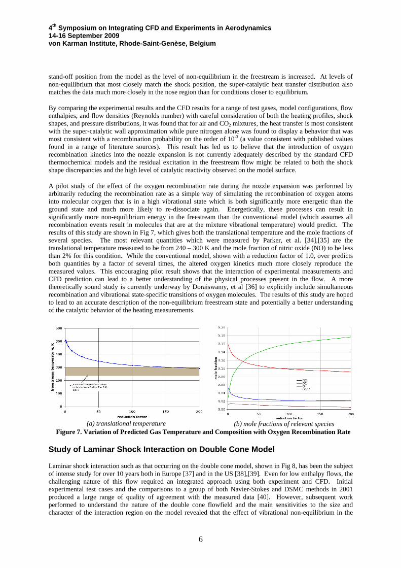
A pilot study of the effect of the oxygen recombination rate during the nozzle expansion was performed by arbitrarily reducing the recombination rate as a simple way of simulating the recombination of oxygen atoms into molecular oxygen that is in a high vibrational state which is both significantly more energetic than the ground state and much more likely to re-dissociate again. Energetically, these processes can result in significantly more non-equilibrium energy in the freestream than the conventional model (which assumes all recombination events result in molecules that are at the mixture vibrational temperature) would predict. The results of this study are shown in Fig 7, which gives both the translational temperature and the mole fractions of several species. The most relevant quantities which were measured by Parker, et al. [34],[35] are the translational temperature measured to be from 240 – 300 K and the mole fraction of nitric oxide (NO) to be less than 2% for this condition. While the conventional model, shown with a reduction factor of 1.0, over predicts both quantities by a factor of several times, the altered oxygen kinetics much more closely reproduce the measured values. This encouraging pilot result shows that the interaction of experimental measurements and CFD prediction can lead to a better understanding of the physical processes present in the flow. A more theoretically sound study is currently underway by Doraiswamy, et al [36] to explicitly include simultaneous recombination and vibrational state-specific transitions of oxygen molecules. The results of this study are hoped to lead to an accurate description of the non-equilibrium freestream state and potentially a better understanding of the catalytic behavior of the heating measurements.
(a) translational temperature (b) mole fractions of relevant species
Figure 7. Variation of Predicted Gas Temperature and Composition with Oxygen Recombination Rate
Study of Laminar Shock Interaction on Double Cone Model
Laminar shock interaction such as that occurring on the double cone model, shown in Fig 8, has been the subject of intense study for over 10 years both in Europe [37] and in the US [38],[39]. Even for low enthalpy flows, the challenging nature of this flow required an integrated approach using both experiment and CFD. Initial experimental test cases and the comparisons to a group of both Navier-Stokes and DSMC methods in 2001 produced a large range of quality of agreement with the measured data [40]. However, subsequent work performed to understand the nature of the double cone flowfield and the main sensitivities to the size and character of the interaction region on the model revealed that the effect of vibrational non-equilibrium in the
6

4th Symposium on Integrating CFD and Experiments in Aerodynamics 14-16 September 2009 von Karman Institute, Rhode-Saint-Genèse, Belgium
nitrogen freestream was significant and remained unaccounted for in the initial set of calculations. This non-equilibrium energy contribution impacted both the attached forebody heating as well as the separation zone size. Additionally, several other factors including grid resolution and numerical dissipation also have a primary effect on the size of the separation region and it is possible to compute a solution where the separation size predicted by the CFD matches the experimentally measured separation size because of cancellation of two competing errors among these sensitivities[41],[42]. The detailed validation of the numerical methods from the CFD simulation required interaction between the CFD and the experiment to fully appreciate these competing dependencies to avoid “computing the right solution for the wrong reasons.” However, when all relevant effects were properly accounted for, excellent agreement can be obtained as shown in Fig 9.
The characterization of this flowfield at high enthalpy where chemical dissociation and thermodynamic excitation occurs has produced a new set of sensitivities which is the subject of ongoing work to challenge the numerical and physical models of the CFD tools. As with the low enthalpy conditions, the double cone flowfield is very sensitive to effects such as chemical relaxation rates [43] and vibration/dissociation coupling [32] which includes the description of the freestream thermochemical state of the test gas as described in the previous section of this paper. In addition to these sensitivities to the physical modeling of the flow, there has been recent interest in the RTO Task Group 43 community in the appearance of computational unsteadiness in a selected test condition that was part of a series of experimental measurements made at enthalpies of 5 and 10 MJ/kg in air and nitrogen [45]. The run in question, Run 40, was observed to be numerically unstable in several of the computations in the sense that the separated region continued to grow past the length measured in the experiment until it reached the front of the model. A qualitatively similar behavior was found by several researchers with different CFD codes, but the experimental data was verified to reach a steady-state, finite separated region size despite the short test time in the facility. The experimental heat transfer is plotted versus distance from the sharp tip of the first cone in two ways in Fig 10. In Fig 10(a), the measured distribution of heating is plotted for several increments of time in 0.25-ms intervals beginning just before the freestream flow arrives in the test section. Over the next 5-ms, the flow is unsteady over the model as the boundary layer develops and the separation region grows. For example, from 9.5-ms to 11-ms, the heat transfer
Figure 8. 25O/55O Double Cone Model in LENS-I
Facility
Figure 9. Comparison of Experiment and Computation for Low Enthalpy Nitrogen Test Case
on Double Cone Model
(b)distribution of data during steady state sub-intervals (a)distribution of data during start-up of viscous flow
Figure 10. Establishment of Heat Transfer over Double Cone Model for Run 40 (N , 5MJ/kg) 2
7

4th Symposium on Integrating CFD and Experiments in Aerodynamics 14-16 September 2009 von Karman Institute, Rhode-Saint-Genèse, Belgium
to the attached forebody of the cone is slightly higher than the steady-state level because the boundary layer has begun to heat the body but is still very thin. As the boundary layer continues to thicken, heating rate drops. During this time, the separation zone size is also growing. By about 12-ms, the flow has stabilized and the distribution of heating remains fixed for the next several milliseconds of flow in the facility as shown in Fig 10(b). Several 1-ms sub-intervals are shown which agree both with each other and with the initially reported mean flow results (also plotted). There is no unsteadiness observed during the experiment during this time interval. By comparing the experiment and the CFD simulation, we can observe that the CFD simulation becomes unsteady in a small fraction of this time interval so there is some discrepancy in the ability of the CFD simulations to re-create this result.
In order to better understand the source of these discrepancies, Nompelis and Candler [44] have performed a study to determine the criteria for stability or instability. They found that stability is a function of Reynolds number, flow enthalpy, and flow chemistry as shown in Fig 11. The stability map bounds a region of high enthalpy and low Reynolds number. Based on the integrated research effort performed to date, we have identified two main deficiencies in our capability to predict the flows over the double cone geometry – (1) the physical modeling associated with thermochemical excitation, and (2) flow unsteadiness in a bounded region of enthalpy and Reynolds number. These two identified deficiencies have been used to target a new set of test data where a series of experiments will be performed to confirm the stability boundary in nitrogen by running a series of lower Reynolds number conditions and a series of experiments will be performed to study the influence of oxygen kinetics on the double cone flowfield. These experiments will be used to advance the state of the CFD numerics and physical models even further.
Figure 11. Map of Numerical Tests Showing Region of Unsteady and Steady Flowfield with N2 Gas
Study of Transitional and Turbulent Heating on HIFiRE-1 Vehicle
A heavy emphasis was placed on the integration between experiments and CFD analysis in the study of the aerothermal design of the HIFiRE-1 vehicle [46] performed in the LENS-I facility [47],[48]. The ground test and design program in the LENS facility focused on measurements to make several key design decisions including selection of the nose radius, the angle of the aft flare, and characterization of transition during the target portion of the trajectory both by natural instability growth and by forced tripping. From this and several other concurrent studies to characterize natural transition onset in the LENS facilities [49], we have established the use of the STABL code to predict 2nd mode transition onset and extrapolate each measurement to quiescent free-flight. An example of this is shown in Fig 12(a), which plots the ground test data and corresponding STABL prediction for a run that duplicates one of the primary trajectory points anticipated for the flight. Assuming an average N-factor of 10.0 for free-flight, the correction to the transition onset point between ground and flight is small for the HIFiRE-1 vehicle. In addition to the capability to make the correction to flight fluctuation environment, it is further possible to adjust for other effects such as wall temperature. A prediction of the flight trajectory with the radiative equilibrium wall is shown in Fig 12(b). As shown, even with the correction for the wall temperature, the transition process occurs in the middle of the cone as it did in the ground test, providing an integrated capability using ground test data and numerical methods to design the flight vehicle to obtain laminar, transitional, and turbulent flow over the cone surface during the flight test.
8

4th Symposium on Integrating CFD and Experiments in Aerodynamics 14-16 September 2009 von Karman Institute, Rhode-Saint-Genèse, Belgium
Downstream of the transition process, the heating due to turbulence in the flow has been considered. Here, shown in Fig 13, one of the initial findings was that several of the most popular RANS models predicted a surprisingly large range of heating rates for a simple cone surface. The result was a general over-prediction of heating compared to the measurements with the popular Shear Stress Transport (SST) model predicting the highest level of heating overall. Despite the addition of the transport equation level physics of such a model, the simple Van Driest-II correlation was a better predictor of the turbulent heating rate. Subsequent to this program, several improvements have been made to the turbulence models in the DPLR code by NASA for application to the Orion program, and these improvements also considerably improve the predictive capability of the code for this flowfield. The old and new SST model prediction is shown, with the improvement in agreement with the data evident.
(a) measured and extrapolated onset for ground
test condition (b) predicted onset for flight condition
(radiative equilibrium wall) Figure 12. Example of 2ND Mode Transition Prediction Compared to Ground Test Measurements and
Extrapolation of the Measured Transition Onset to Flight
Figure 13. Measurement and Prediction of Turbulent Heating on HIFiRE-1 Cone Surface
Finally, by comparing with the data on the separated region over the flare, the same RANS models were also shown to poorly predict the size and character of the separated region. The issue for this flowfield was found to be tied to the rate of production of turbulent kinetic energy (or turbulent eddy viscosity) that was caused by the separation shock. The predictions are shown compared to a Schlieren photograph from the experiment in Fig 14(a). Too large a production rate causes the separated region to be too small (as in the Spalart-Allmaras model) while a production rate that is too aggressively limited causes the separated region to be too large (as in the SST model). Simple improvements in the turbulence models were made to the calculation of eddy viscosity with both models to significantly improve the prediction of this flowfield. The models with the modified eddy viscosity production rate are shown in Fig 14(b), which demonstrates significantly improved agreement. This modified capability has been employed to design several new models to study turbulent boundary layer separation and shock interaction including a large cone-flare, a cylinder with external shock generator, and a backward facing step that are being used to generate a new experimental dataset for detailed CFD code validation of next-generation tools.
9

4th Symposium on Integrating CFD and Experiments in Aerodynamics 14-16 September 2009 von Karman Institute, Rhode-Saint-Genèse, Belgium
(a) experiment compared to original turbulence models
(b) experiment compared to modified turbulence models
Figure 14. Comparison of Predicted to Measured Separated Region with Original and Modified Spalart-Allmaras and SST RANS Models
Study of Inlet Starting on Planar Scramjet Inlet
We also consider one other application where integration of CFD and experiments has been found to be inherently necessary. In the study of dynamic events such as inlet starting and mode-switching for high-speed propulsion, measurements of the distribution of surface pressure or heat transfer are impossible to properly interpret to assess what the state of the flowfield is at a given time without supporting CFD simulations. The integration of the two helps us to understand when an inlet is unstarted or becomes started.
One such example of this type of integrated analysis was performed under the MURI program to study mode switching from a high-speed turbine mode to a ramjet mode via the cycling of a pair of doors to control the airflow in a low-speed flowpath and a high-speed flowpath. The model is shown in Fig 15 and a schematic of the two modes of operation of the inlet are shown in Fig 16. The program actually studied several configurations loosely organized by the direction of action of the low-speed flowpath door. The two geometries
Figure 15. Turbine Door Inlet Model
(a) low-speed flowpath open (b) high-speed flowpath open
Figure 16. Schematics of Forward-Facing Turbine Door Inlet
10

4th Symposium on Integrating CFD and Experiments in Aerodynamics 14-16 September 2009 von Karman Institute, Rhode-Saint-Genèse, Belgium
were a forward hinging door and a rear hinging door.
The difference between these two mechanisms was principally in the strength of the transient shocks impinging in the low-speed duct interior. For each of the two sub-configurations, several designs were constructed and tested to change the dynamics of the shock interaction during the cycling of the doors. For each configuration, CFD was used to compute the steady, started solution of the duct and compared to the measurements made. Using the measurements and the CFD flowfields to look at shock strength, angles, and dynamics, the optimum door geometry to start the low-speed flowpath and then switch to the high-speed flowpath was found.
The sequence of timing in the facility is shown in Fig 17, which covers the establishment of the low-speed flow, closing of the low-speed door, opening of the high-speed door, and establishment of steady flow through the high-speed duct. Unsteady pressure and heating were measured during these events with the different geometries. An example of the comparison to CFD is shown in Fig 18, which plots pressure at several instants in time against the fully started CFD prediction. It is clear that the dynamics of the data are complex, but the CFD shows that the blue and purple time indices are closest to being fully-started. In particular, the two gages closest to a location of 60” show a transient behavior where the pressure is higher than the CFD prediction for a short time, but then falls in line with the prediction as the flow becomes more closely aligned with the shape of the CFD solution.
Figure 18. Sample Pressure Distributions compared to CFD
Solution for Started Inlet Surface Figure 17. Timing Sequence in LENS-II Facility for Mode Switching
Study
We are beginning to explore the process of performing time-accurate, unsteady CFD simulations and integrating that capability with experiments, but those calculations are very computationally intensive. We find that a great deal of information can be learned by using CFD to compute the bounding states of the dynamic system to understand how close to steady-state it reaches.
Integrating CFD and Experiment: Lessons Learned
Because we have made the integration of CFD and experiments a priority in the operation of the LENS shock tunnels in the past seven years, several of the key lessons learned can be summarized from this process:
• CFD simulations should be employed in every phase of an experimental program: (1) design, (2) test and instrumentation planning, (3) real-time data validation, and (4) post-test analysis. This is necessary to insure good quality test data that targets the proper physical phenomena of interest.
• CFD simulations may be most effectively used in conjunction with experimental programs that measure detailed surface distributions of pressure and heat transfer by comparing the CFD predictions of the measurements. If the CFD code can be shown to predict these distributions adequately, then the numerical solution flowfields may be interrogated to better understand the physical processes driving those distributions.
11
4th Symposium on Integrating CFD and Experiments in Aerodynamics 14-16 September 2009 von Karman Institute, Rhode-Saint-Genèse, Belgium
• In order to be meaningful, the CFD simulations must be performed at a rate that keeps pace with the facility operational requirements. By this, we mean that the CFD simulations have to be converged rapidly enough to be of use during the test program to make decisions about each run and determine direction for the next run. For the LENS facilities, runs typically are made about every four hours during the workday so a CFD simulation must be completed the same day or overnight. This pace requires that studies of grid resolution and other sensitivities be performed before the test begins and to prioritize about which quantities and regions of the test article need to be simulated. Further, we must select the best numerical methods that insure robust and very rapid convergence to meet the scheduling needs. A high quality CFD simulation that is not available until after the test program has been completed in not useful for real-time validation.
• It is important for CFD researchers to be physically present during the experimental setup and initial data analysis not only to validate and verify the results where possible, but also to observe the experimental arrangements in detail, ask questions, document the way things were done, ask for specific measurements or pieces of information, etc.
• It is only through constant comparison of the CFD solutions and experimental data that we develop the expertise to understand the physical phenomena associated with the hypervelocity test articles. By repeated efforts in this area, we are better able to prioritize simulations, more readily understand design changes, and develop numerical grids and physical test articles that target the physics that we are interested in without wasting unnecessary time or resources on unimportant issues. The most successful efforts have been made by performing and experiment, using those results to validate and improve the numerical modeling of that flowfield, and then using the improved numerical tool to design a better second-generation experiment.
Conclusions
It has been shown through several example programs that it is necessary to integrate CFD and experiments in a tightly coupled manner to make a proper study of the fundamental phenomena of hypersonic flows. Because of the highly complex nature of hypersonic vehicles, measurements do not lend themselves to simple interpolation or readily available empirical rules so CFD simulations must be employed to both validate the data and to explain the phenomena causing complex changes in the flow that the measurements respond to. By coupling the two efforts together in real-time, it is possible to more readily advance the state-of-the-art of both experiments and simulations to provide high-quality, validated datasets and robust, physically meaningful physical and numerical models.
It is best to conclude by looking briefly at some of the ways in which the integration of the CFD and experiments that has been accomplished over the past several years is driving improvements in future experiments. Because of the things that we have learned in making comparisons, experiments are being targeted in new directions. First, because of the findings with regard to thermochemical excitation and relaxation in high enthalpy flows in the reflected shock tunnels facilities, CUBRC has designed and built a new expansion tunnel facility, LENS-XX. The expansion tunnel operates by directly adding kinetic energy to the test gas rather than stagnating it. Because the test gas is never raised to high temperatures as in the reservoir of the reflected shock tunnels, the freestream gas is more easily described and understood and it is closer to the quiescent state of free-flight. Although the reflected shock tunnels remain a core capability for CUBRC’s high-speed testing, the expansion tunnel facility adds to our capability to test very high velocity flows for reentry applications and planetary exploration missions. The LENS-XX facility has been made operational, completed a series of “shake-down” runs, and will be employed in several studies in the near future.
Second, a future emphasis on testing at all speeds in the hypersonic regime will be focused on making measurements with non-intrusive diagnostics for flowfield interrogation, line-of-sight measurements, turbulence information and other quantities away from the surface of the vehicle. This new focus has also been a result of continuing to compare the CFD to experimental surface measurements. After several years of this effort, we have developed an understanding of the things that even the best CFD codes are able to accurately predict and the things that they are not. In order to further advance CFD codes, it is necessary to experimentally explore the shock layer physics in a detailed manner to provide broader feedback to CFD developers.
12

4th Symposium on Integrating CFD and Experiments in Aerodynamics 14-16 September 2009 von Karman Institute, Rhode-Saint-Genèse, Belgium
References
[1] Holden, M.S. and Parker, R.P. “LENS Hypervelocity Tunnels and Application to Vehicle Testing at Duplicated Flight Conditions,” Advanced Hypersonic Test Facilities. Lu, F.K. and Marren, D.E. Eds. AIAA Progress in Astronautics and Aeronautics Series: Vol. 198, Chp. 4. Reston, VA: American Institute of Aeronautics and Astronautics, 2002.
[2] Holden, M.S.; Wadhams, T.P.; and Candler, G.V. “Experimental Studies in the LENS Shock Tunnel and Expansion Tunnel to Examine Real-Gas Effects in Hypervelocity Flows”. AIAA Paper 2004–0916. January 2004.
[3] Wright, M.J.; Bose, D.; and Candler, G.V. “A Data Parallel Line Relaxation Method for the Navier-Stokes Equations”. AIAA Journal. Vol 36, no 9. Pgs 1603 – 1609. Sept 1998.
[4] MacCormack, R.W. and Candler, G.V. “The Solution of the Navier-Stokes Equations Using Gauss-Seidel Line Relaxation”. Computers and Fluids. Vol 17, No 1. Pgs 135 – 150. 1989.
[5] Candler, G.V. “Chemistry of External Flows”. Aerothermochemistry for Hypersonic Technology: Von Karman Institute for Fluid Dynamics Lecture Series. VKI LS 1995-04.
[6] Landau, L. and Teller, E. “Theory of Sound Dispersion”. Physikalische Zeitschrift der Sowjetunion. Vol 10, no 34. 1936.
[7] Millikan, R. and White, D. “Systematics of Vibrational Relaxation”. Journal of Chemical Physics. Vol 39, no 12. Pgs 3209 – 3213. 1963.
[8] Camac, M. “CO2 Relaxation Processes in Shock Waves”. Fundamental Phenomena in Hypersonic Flow. J.G. Hall Ed. Cornell University Press. Pgs 195 – 215, 1964.
[9] Park, C.; Howe, J.T.; Jaffe, R.J.; and Candler, G.V. “Review of Chemical-Kinetic Problems of Future NASA Missions II: Mars Entries”. Journal of Thermophysics and Heat Transfer. Vol 8, no 1. Pgs 9 – 23. 1994.
[10] Park, Chul. “Assessment of Two-temperature Kinetic Model for Ionizing Air”. AIAA Paper 87-1574. AIAA 22ND Thermophysics Conference. Honolulu, HI: 8-10 June 1987.
[11] Marrone, P.V. and Treanor, C.E. “Chemical Relaxation with Preferential Dissociation from Excited Vibrational Levels”. The Physics of Fluids, Vol 6, no 9. Pgs 1215 – 1221. September 1963.
[12] Palmer, G.E. and Wright, M.J. “A Comparison of Methods to Compute High Temperature Gas Viscosity”. Journal of Thermophysics and Heat Transfer. Vol 17, no 2. Pgs 232 – 239. 2003.
[13] Palmer, G.E. and Wright, M.J. “A Comparison of Methods to Compute High Temperature Gas Thermal Conductivity”. AIAA Paper 2003-3913. Jun 2003.
[14] Gupta, R.; Yos, J.; Thompson, R.; and Lee, K. “A Review of Reaction Rates and Thermodynamic and Transport Properties for an 11-Species Air Model for Chemical and Thermal Nonequilibrium Calculations to 30000 K”. NASA RP-1232. August 1990.
[15] Ramshaw, J.D. “Self-consistent Effective Binary Diffusion in Multicomponent Gas Mixtures”. Journal of Non-Equilibrium Thermodynamics. Vol 15, no 3. Pgs 295 – 300. 1990.
[16] Baldwin, B.S. and Lomax, H. “Thin Layer Approximation and Algebraic Model for Separated Turbulent Flows”. AIAA Paper 78-0257. Huntsville, AL: 1978.
[17] Spalart, P.R. and Allmaras S.R. “A One-Equation Turbulence Model for Aerodynamic Flows”. AIAA Paper 92-0439. 30TH Aerospace Sciences Meeting & Exhibit. Reno, NV: 6-9 Jan, 1992.
[18] Menter, F.R. “Two-Equation Eddy-Viscosity Turbulence Models for Engineering Applications”. AIAA
13

4th Symposium on Integrating CFD and Experiments in Aerodynamics 14-16 September 2009 von Karman Institute, Rhode-Saint-Genèse, Belgium
Journal. Vol 32, no 8. Pgs 1598 – 1605. August 1994.
[19] Brown, James. “Turbulence Model Validation for Hypersonic Flow”. AIAA Paper 2002-3308. 8TH Thermophysics and Heat Transfer Conference. St. Paul, MN: 24 – 26 Jun 2002.
[20] Catris S. and Aupoix B. “Improved Turbulence Models for Compressible Boundary Layers.” AIAA Paper 98-2696. 2ND Theoretical Fluid Mechanics Meeting: Albuquerque, NM, June 1998.
[21] Saunders, D.; Yoon, S.; and Wright, M. “An Approach to Shock Envelope Grid Tailoring and Its Effect on Reentry Vehicle Solutions,” AIAA Paper 2007-0207. 45TH Aerospace Sciences Meeting & Exhibit. Reno, NV: 8-11 January 2007.
[22] Candler, Graham V. “Hypersonic Nozzle Analysis Using an Excluded Volume Equation of State”. AIAA Paper 2005 – 5202. 38TH AIAA Thermophysics Conference, Toronto, CA: 6 – 9 June 2005.
[23] MacLean, M.; Candler, G.; and Holden, M. “Numerical Evaluation of Flow Conditions in the LENS Reflected Shock-Tunnel Facilities”. AIAA Paper 2005-0903. 43RD Aerospace Sciences Meeting & Exhibit. Reno, NV: 10-14 January 2005.
[24] Lordi, J.A. and Mates, R.E. “Non-equilibrium Expansions of High-Enthalpy Airflows.” Cornell Aeronautical Laboratory Report, ARL 64-206. November 1964.
[25] Johnson, Heath B. Thermochemical Interactions in Hypersonic Boundary Layer Stability. Ph.D. Thesis, University of Minnesota, Minneapolis, MN, 2000.
[26] Johnson, H. and Candler, G. “Hypersonic Boundary Layer Stability Analysis Using PSE-Chem.” AIAA Paper 2005-5023. 35TH AIAA Fluid Dynamics Conference and Exhibit, Toronto, ON. June 2005.
[27] Johnson, H. and Candler, G. “Analysis of Laminar-Turbulent Transition in Hypersonic Flight Using PSE-Chem.” AIAA Paper 2006-3057. 36TH AIAA Fluid Dynamics Conference and Exhibit, San Francisco, CA. 5 – 8 June 2006.
[28] Herbert, T. “Boundary Layer Transition – Analysis and Prediction Revisited.” AIAA Paper 91-0737. January, 1991.
[29] J.A. Lordi, R.E. Mates and J.R. Moselle (1965) “Computer program for the numerical solution of Nonequilibrium expansions of reacting gas mixtures. NASA-CR-472.
[30] MacLean, M. and Holden, M. “Numerical Assessment of Data in Catalytic and Transitional Flows for Martian Entry.” AIAA Paper 2006-2946. 9TH AIAA/ASME Joint Thermophysics and Heat Transfer Conference, San Francisco, CA: 5-8 June 2006.
[31] MacLean, M.; Mundy, E.; Wadhams, T.; Holden, M.; Parker, R. “Analysis and Ground Test of Aerothermal Effects on Spherical Capsule Geometries.” AIAA Paper 2008-4273. 38TH AIAA Fluid Dynamics Conference & Exhibit, Seattle, WA: 22-26 June 2008.
[32] MacLean, M.; Wadhams, T.; Holden, M.; Parker, R. “A Computational Analysis of Thermochemical Studies in the LENS Facilities.” AIAA Paper 2007-0121. 45TH AIAA Aerospace Sciences Meeting & Exhibit, Reno, NV: 8-11 January 2007.
[33] MacLean, M. and Holden, M. “Assessment of Aerothermal Heating Augmentation Attributed to Surface Catalysis in High Enthalpy Shock Tunnel Flows,” Proc. of ‘The 6TH European Symposium on Aerothermodynamics for Space Vehicles’, (ESA SP-659, January 2009), Versailles, France, 3–6 November 2008.
[34] Parker, R.; Wakeman, T.; MacLean, M.; and Holden, M. "Nitric Oxide Concenttration Measurements with a Quantum Cascade Laser in the LENS I Hypersonic Shock Tunnel Facility." AIAA Paper 2006-0926. 44TH Aerospace Sciences Meeting & Exhibit. Reno, NV: 9-12 January 2006.
14

4th Symposium on Integrating CFD and Experiments in Aerodynamics 14-16 September 2009 von Karman Institute, Rhode-Saint-Genèse, Belgium
[35] Parker, R.; Wakeman, T.; MacLean, M.; and Holden, M. "Measuring Nitric Oxide Freestream Velocity Using a Quantum Cascade Laser at CUBRC." AIAA Paper 2007-1329. 45TH AIAA Aerospace Sciences Meeting & Exhibit, Reno, NV: 8-11 January 2007.
[36] Doraiswamy, S.; Kelley, D.; and Candler, G. “Analysis of Chemistry-Vibration Coupling in Diatomics for High Enthalpy Nozzle Flows,” AIAA Paper #2010-1570. 48TH AIAA Aerospace Sciences Meeting & Exhibit, Orlando, FL: 4-7 January 2010.
[37] Chanetz, B.; Benay, R.; Bousquet, J.-M.; Bur, R.; Oswald, J.; Pot, T.; Grasso, F.; and Moss, J. “Experimental and Numerical Study of the Laminar Separation in Hypersonic Flow,” Aerospace Science and Technology, No 3, Pgs 205 – 218. 1998.
[38] Wright, M.J.; Sinha, K.; Olejniczak, J.; Candler, G.V.; Magruder, T.D.; and Smits, A.J. “Numerical and Experimental Investigation of Double-Cone Shock Interactions,” AIAA Journal, Vol 38, No 12, Pgs 2268 – 2276. December 2000.
[39] Holden, M.S.; Wadhams, T.P.; Harvey, J.K.; and Candler, G.V. “Comparisons between DSMC and Navier-Stokes Solutions on Measurements in regions of Laminar Shock Wave Boundary Layer Interaction in Hypersonic Flows,” AIAA Paper 2002-0435. 40TH AIAA Aerospace Sciences Meeting & Exhibit, Reno, NV: 14-17 January 2002.
[40] Harvey, J.K.; Holden, M.S.; and Wadhams, T.P. “Code Validation Study of Laminar Shock/Boundary Layer and Shock/Shock Interactions in Hypersonic Flow, Part B: Comparisons with Navier-Stokes and DSMC Calculations,” AIAA Paper 2001-1031(B). 40TH AIAA Aerospace Sciences Meeting & Exhibit, Reno, NV: 8–12 January 2001.
[41] Nompelis, I.; Candler, G.; and Holden, M. “Effect of Vibrational Nonequilibrium on Hypersonic Double-Cone Experiments,” AIAA Journal, Vol 41, No 11, Pgs 2162 – 2169. November 2003.
[42] Druguet, M.-C.; Candler, G.V.; and Nompelis, I. “Effect of Numerics on Navier-Stokes Computations of Hypersonic Double-Cone Flows,” AIAA Journal, Vol 43, No 3. Pgs 616 – 623. March 2005.
[43] Druguet, M.-C.; Candler, G.V.; and Nompelis, I. “Comparison of Physical Models in Computations of High-Enthalpy Double-Cone Flows,” AIAA Paper 2006–3419. 9TH AIAA/ASME Joint Thermophysics and Heat Transfer Conference, San Francisco, CA: 5–8 June 2006.
[44] Nompelis, I. and Candler, G. “Numerical Investigation of Double-Cone Flows with High Enthalpy Effects,” Proc. of ‘The 6TH European Symposium on Aerothermodynamics for Space Vehicles’, (ESA SP-659, January 2009), Versailles, France, 3–6 November 2008.
[45] Holden, M.S.; Wadhams T.P; Candler, G.V.; and Harvey, J.K. “A Review of Experimental Studies for DSMC and Navier-Stokes Code Validation in Laminar Regions of Shock/Shock and Shock/Boundary Layer Interaction Including Real Gas Effects in Hypervelocity Flows,” AIAA Paper 2003-3641. 36TH AIAA Thermophysics Conference, Orlando, FL: 23–26 June 2003.
[46] Kimmel, R. “Aerothemal Design for the HIFiRE Flight Vehicle,” AIAA Paper 2008-4034. 38TH AIAA Fluid Dynamics Conference & Exhibit, Seattle, WA: 22-26 June 2008.
[47] Wadhams, T.; Mundy, E.; MacLean, M.; and Holden, M. "Ground Test Studies of the HIFiRE-1 Transition Experiment Part 1: Experimental Results," Journal of Spacecraft and Rockets. Volume 45, number 6. Pages 1134-1148. November-December 2008.
[48] MacLean, M.; Wadhams, T.; Holden, M.; and Johnson, H. "Ground Test Studies of the HIFiRE-1 Transition Experiment Part 2: Computational Analysis," Journal of Spacecraft and Rockets. Volume 45, number 6. Pages 1149-1164. November-December 2008.
[49] MacLean, M.; Mundy, E.; Wadhams, T.; Holden, M.; Johnson, H.; Candler, G. "Comparisons of Transition Prediction using PSE-Chem to Measurements for a Shock Tunnel Environment." AIAA Paper 2007-4490. 37TH AIAA Fluid Dynamics Conference & Exhibit, Miami, FL: 25 - 28 June 2007.
15