model of exhaust system of a traction diesel engine with ... · model of exhaust system of a...
TRANSCRIPT

Article citation info:
BABEL, M., KOSSOV, E. Model of exhaust system of a traction diesel engine with pulse supercharging on transient modes. Combustion
Engines. 2017, 168(1), 38-45. DOI: 10.19206/CE-2017-106
38 COMBUSTION ENGINES, 2017, 168(1)
Marek BABEL CE-2017-106 Evgeni KOSSOV
Model of exhaust system of a traction diesel engine with pulse supercharging
on transient modes
A mathematical model of joint operation of a piston engine with pulse turbine drive, compressor as well as air supply of a diesel
locomotive is presented in the article. This model in an integral part of the complex engine-generator power unit of a diesel locomotive
in steady states and transient conditions, developed by the authors.
The periodic process in the exhaust manifold is represented as two specific characteristic ranges which encompass the process of
forced exhaust and the scavenging process. The scavenging calculation is carried out jointly with the processes taking place in the inlet
manifold of the engine, including inlet devices of the locomotive. The process of forced exhaust is calculated separately from the inlet
processes and doesn`t require usage of empirical coefficients of impulsiveness. Both processes are represented as systems of nonlinear
algebraic equations describe in the quasi-steady flow of working fluid in the elements of the inlet and exhaust tracts. The gas-dynamic
calculation of the turbine in the transition process is conducted while taking into account changes in flow angles on the rotor blades. As
a result of numerical calculation of the a8S22W diesel operational indices in transient modes, a satisfactory compliance of the calculated
and the experimental results was obtained.
Key words: diesel engine, locomotive, mathematical model, pulse supercharging, exhaust system, transient process
1. Introduction
The analysis of the operating modes of the diesel engine shows that the engine runs on transient mode for a considerable part of the operation time.The transient modes, accompanying acceleration of the engine, are characterized by sharp increasing of fuel supply into the cylinder of engine and as a result by a reduction of the air excess coefficient λ, reduction of indicated efficiency ηi, significant peak temperature increase of exhaust gases Tt, incomplete combustion of fuel and other negative effects. A lot of such effects are excluded by using pulse super-charging.
Experimental studies of an operation of the diesel generator with pulse supercharging when momentary changes of load showed that the ratio of pressure in the inlet manifold Ps to pressure in front of the turbine Pt, is practically always larger than one throughout in the whole period of transient process. This parameter is one of the determining factors of the preference of using pulse supercharging system. The advantages of the pulse supercharging system are a better use of exhaust gases energy, which facilitates the increase in the torque of the turbine and improving the air supply of the diesel engine in the transient processes.
One of the most effective methods of studying the performance of the diesel locomotive engine with pulse supercharging in operation is a mathematic modelling of its working processes with a computer. It allows analysis of the working parameters of a diesel locomotive in exploitation, to determine and indicate the most efficient factors for improvement of the parameters already at the stage of design, tests and modernisation of engine systems.
This task can be achieved if the complex model of the engine-generator unit operation of a diesel locomotive in steady and transient modes is developed. This model should include a traction diesel engine – the piston part with its systems – inlet, exhaust and a turbocharger, locomotive transmission: – electric or hydraulic as well as auxiliary
equipment on the vehicle. Development of such a model requires creation of mathematical models for above-mentioned components and systems. The model of the diesel locomotive power unit (system) obtained in this way will be used for simulation research (optimization) of influence of the revolution and power control system of the power unit on the energy efficiency of power transmission. Compliance of the model with the real processes, and also compactness and versatility of the description of processes for different types of engines and air aggregates are significant criteria of applicability of the mathematic model.
In [29] the authors reviewed 155 foreign publications concerning diesel engine simulations under transient operating modes in the open literature in the years 1971-2006. Most of these works (over 90%) concern simulation models of automotive engines as the research object, and about 5% marine engines. In this article, the authors summarize basic equations and modelling aspects concerning in-cylinder calculations, friction, turbocharger, engine dynamics, governor, fuel pump operation, and exhaust emissions during transients. The various limitations of the models are discussed together with the main aspects of transient operation (e.g. turbocharger lag, combustion and friction deterioration), which diversify it from the steady-state.
The general classification of the operating models of the piston engine cycle, known from the Polish literature, is described in [30], and the theoretical basics of fuel and air supply modelling of engines – in [35]. Implementation of mathematical models of diesel engine processes for simulation research of exhaust emissions are described in [12, 22, 26], and in publication [36], the model of diesel engine heat circulation is used for optimization of the research engine operation.
In the field of mathematic modelling of operation of automotive engines, most papers relate to control in engine systems with taking into account the transient modes [7, 13, 18, 24, 39].

Model of exhaust system of a traction diesel engine with pulse supercharging on transient modes
COMBUSTION ENGINES, 2017, 168(1) 39
A representation of conditions of the joint piston part and turbocharger operation in the form of calculations is a difficult task. It requires an accurate determination of the conditions of airflow and exhaust gases flow through the turbocharger. In [6, 19, 20, 27, 32], some alternative methods of solving the task are presented. They are different both in essence and accuracy.
The design of a model of the diesel with a turbocharger requires a mathematical description of the compressor and turbine. For solving this task, analytic methods [28, 31], which allow for calculating the hydraulic and thermal losses in the flow part of the turbine and turbocharger, can be used. Another method uses experimental characteristics of turbocharges for modelling, as functional relations – approximation of characteristics by polynomials of highest degree [8, 14, 15, 40].
Some mathematic models of the transient processes of diesel engines are based on the assumption that the diesel engine operation can be presented with a system of five differential equations [37]. The authors represented general differential equations without analysing the equations which express the relationship between concrete parameters of the engine. In [16], the mathematic model of the transient conditions of a marine diesel with pulse supercharging was elaborated based on the system of seven differential equations. The flow impulsiveness of exhaust gases is taken into account here by means of the correction factors obtained from experimental studies. The mathe-matical model of transient processes represented in [8] is also of interest. This model is based on a system of n differential equations for the piston part and of 6 equations describing the processes in the exhaust manifold in the case of using pulse supercharging. The mathematical models of transient modes of diesels in [38, 41] are based on similar principles. However, it is necessary to state that these models require a lot of computations and the presence of standard subprograms in the computer database. The precision of the model depends on the solution of the system of differential equations which is connected with the time of calculation.
For taking into account the pulsation of the mass flow which is delivered to the turbine at pulse supercharging, in [42] a coefficient α was entered, and to take into account the energy delivered at changeable pressure of gases, a coefficient β was entered. In [14, 15], impulsiveness of the flow of exhaust gases is taken into account with correction coefficients kG, kH and kS for determining values of momentary growth of consumption of gas and pressure and also of changes in turbine efficiency. These coefficients are obtained based on analysis of diagrams of changes in gas pressures in the exhaust manifold for a certain number of engines. These coefficients are represented as approximate relations dependent on the pressure ratio πk.
A systematization of coefficients type α, β, kG, kH, kS is complicated due to large number of criteria, which have different effects on the shape of the curve of gases pressure in the exhaust manifold.
The authors of this article analysed the possibility of application of the existent mathematic model of the transient process of a diesel with the isobaric supercharging
system [21] for the calculation of characteristics of the diesel with a pulse supercharging system.
The method of implementation static characteristics of diesel and supercharging aggregates in the mathematic model, as well as the calculation of a compressor and inlet system, are analysed in detail in [1, 21, 23]. A calculation of the transient processes performed in accordance with this method, while taking into consideration the pulse coefficients for determination of the power and the pressure of the turbine, showed that the condition Рs/Pt >1 is not met, and the estimated time of transient process calculation is considerably prolonged [1]. The inclusion of calculations of the gas exchange process in this method, in order to achieve a more precise determination of the momentary values of gas parameters in the exhaust manifold, makes the mathematic model more complicated and useless for optimization calculations.
In [5, 9, 10, 25, 33], the authors described some interesting simulation models of diesel engine operation in steady conditions and transient states while using 1D models for turbocharger and chosen processes of diesel engines, and in publications [11, 17, 34] 3D CFD models. In these works, the research (modelling) object is, among others, a pulse-charged turbine in application for mainly automotive engines. In this scope of research, imple-mentation of 1D and 3D models allows for effective simulation of the diesel engine processes chosen by the researchers. The object of research (modelling) and optimization calculations done by the authors of this article is the diesel locomotive power system, and the model of the exhaust system with pulse turbine supply is only an element of the above-mentioned complex model. Development of such a model implementing the 1-D modelling suggested by the researchers is a complex problem due to the variety of processes in the individual elements and systems of the diesel locomotive power unit and due to the limitation in the technical capabilities of computers. As it was indicated in the introduction to the chapter, the mathematical model should be compact, universal and suitable for multiple optimization calculations.
Given the above, the authors proposed a different approach to modelling of diesel engine exhaust system with pulse turbine supply which does not require implementation of differential equations for calculation of gas exchange, using experimental pulse indices or creation of complex, 1D or 3D models, e.g. for the piston part of the traction diesel engine, turbocharger.
2. Modelling of a diesel engine exhaust system Based on modelling of the traction diesel engine,
a quasi-steady model of working fluid flow in engine and turbocharging system elements was used [21]. The quasi-steady flow model allows for achieving satisfactory correspondence of the numerical calculation results to the experimental results [2, 32].
While creating the model it was proposed that the change in gas pressure in the exhaust manifold of diesel was dependent on time or on crankshaft angular velocity ωd represents a periodic function with the period:
T = ωd∙ φ* (1)

Model of exhaust system of a traction diesel engine with pulse supercharging on transient modes
40 COMBUSTION ENGINES, 2017, 168(1)
where ωd, φ* – crankshaft angular velocity and period of change in gas pressure.
The period of changes in gas pressure in the manifold φ* will be equal to the value of phase shift of cylinder operation. We will assume that periodic process in the manifold may be represented in the form of some sequence of processes with the duration ∆φ inter-related by boundary conditions. There can be many such consecutive processes, however in relation with the processes in the inlet manifold, there are two specific periods: a process of forced exhaust (angle φex–φin) and a scavenging process (angle φin–φexe, see Fig. 1a).
In the engine with pulse supercharging, the process of forced exhaust is completely isolated from the processes in the inlet manifold and it can be calculated based on the known methods if the parameters of the working fluid in the cylinder are set. The scavenging process is directly connected with the processes in the inlet manifold. In this work, it is suggested to calculate the scavenging process together with the processes in the inlet tract of the engine including the inlet equipment of diesel locomotive, air filter 1, compressor 2, intercooler 3, piston part 4, turbine 7 and exhaust equipment 8. (see Fig. 1b). The process of forced exhaust is calculated separately from the inlet processes. Both processes are presented by systems of nonlinear algebraic equations, which describe quasi-stationary flow of working fluid in the elements of the inlet and exhaust tracts. As in [21, 23], systems of algebraic equations are complemented by a system of differential equations, which describe changes in temperatures of heat carrier, of exhaust tract elements and of turbocharge rotor speed depending on time. The calculation of the flow of working fluid in the scavenging process and the exhaust process is carried out subsequently by taking the average values of pressure, temperature and working fluid flow rate in the corresponding periods with the assumed period ∆φ (see Fig. 1a). The initial parameters for a calculation of the exhaust tract with forced exhaust are the parameter values determined while calculating exhaust manifold during scavenging.
A working fluid flow rate (of air-gas mixture) in the diesel, Gag, is represented by a sum of air flow rate in the scavenging process of cylinders, Gsc, and for filling cylinders from the moment of exhaust valves closure to bottom-dead-point, Gd.
It was assumed, that at the end of filling (in the cylinder) there will be a mass of working medium equal to the sum of the mass from the filling process and the mass present in the cylinders at the closure moment of the exhaust valves.
At pulse supercharging, GSC > 0 which demonstrates why the pressure in the exhaust manifold behind the cylinder at the scavenging process will be determined by means of relation: P���� � P� π�⁄ (2)
where P� – pressure of working fluid before inlet valves πd – ration of intake manifold pressure and exhaust manifold pressure.
Fig. 1. Change in pressure in exhaust manifold (а) calculation model of а8С22 diesels with pulse supercharging at scavenging (b) and at free
exhaust (c) From the energy-conservation equation we determine
the temperature of air-gas mixture in manifold at scavenging process (see Fig. 1b): T10sc∙�Gsc�GVc�∙Cpag�T6∙Gsc∙Cpa�T10ex∙GVc∙Cpex �3�where G � – working fluid flow rate at exhaust, which corresponds with the mass, contained in cylinders at the moment of opening of the exhaust valves; Срag, Срa, Срex – heat capacity at constant pressure of air-gas mixture, air dose, working fluid at exhaust process, respectively; T� – temperature of air dose;
Working fluid flow rate,G �,can be determined from equation: G � � V! ∙ ω� ∙ z��ε % 1� ∙ 2π ∙ τ ∙ ρ)*+ �4�where Vh, ω�– cylinder capacity and crankshaft angular speed;z�, ε, τ – respectively: the number of cylinders, compression rate and the number of crank revolutions per power stroke;ρ)*+ – gas density at temperature T10ex and pressure P10ex.
If we assume that heat capacity at a constant pressure of air-gas mixture, air dose and exhaust gases are constant and equal (Срag≈ Срa ≈ Срex), then from the equation (3) and (4) we obtain: T����� -T� ∙ G�� � G � ∙ P��*+ ∙ R)/�0 -G�� � G � ∙ ρ)*+01 �5�
In calculations it is assumed that at time Δφ/ωd of scavenging, average gas flow rate G) is determined by scavenging air flow rate G��. The pressure of working fluid before turbine P�3�� is determined from equation: P�3�� � P���� π��⁄ (6)
where π�� – pressure differential in conditional diaphragm 6 (see Fig. 1b).
Model of exhaust system of a traction diesel engine with pulse supercharging on transient modes
COMBUSTION ENGINES, 2017, 168(1) 41
The average working fluid flow rate at time Δφ/ωd of forced exhaust is determined as a sum of gas flow rate Gd
for filling cylinders and fuel mass flow rate b5�. G) � G� � b5� (7)
The temperature of the exhaust gases T��*+ is determined by the heat balance while taking into account the heat losses from incomplete burning of fuel according to the following equation: T��*+ � b5� ∙ H7 ∙ �ξ % η: % ξ��G) ∙ C;*+ � G�G) ∙ T���� (8)
where H7 – calorific value of fuel; ξ – available heat factor at the end of expansion process; ξ� –coefficient taking into account share of unburned fuel; η: – efficiency indicator of diesel engine, and the gas pressure before turbine P12ex – according to equation (6).
The temperature of gases before turbine T12sc, T12ex is determined by taking into account the heat exchange in exhaust manifold by means of method described in [21, 23].
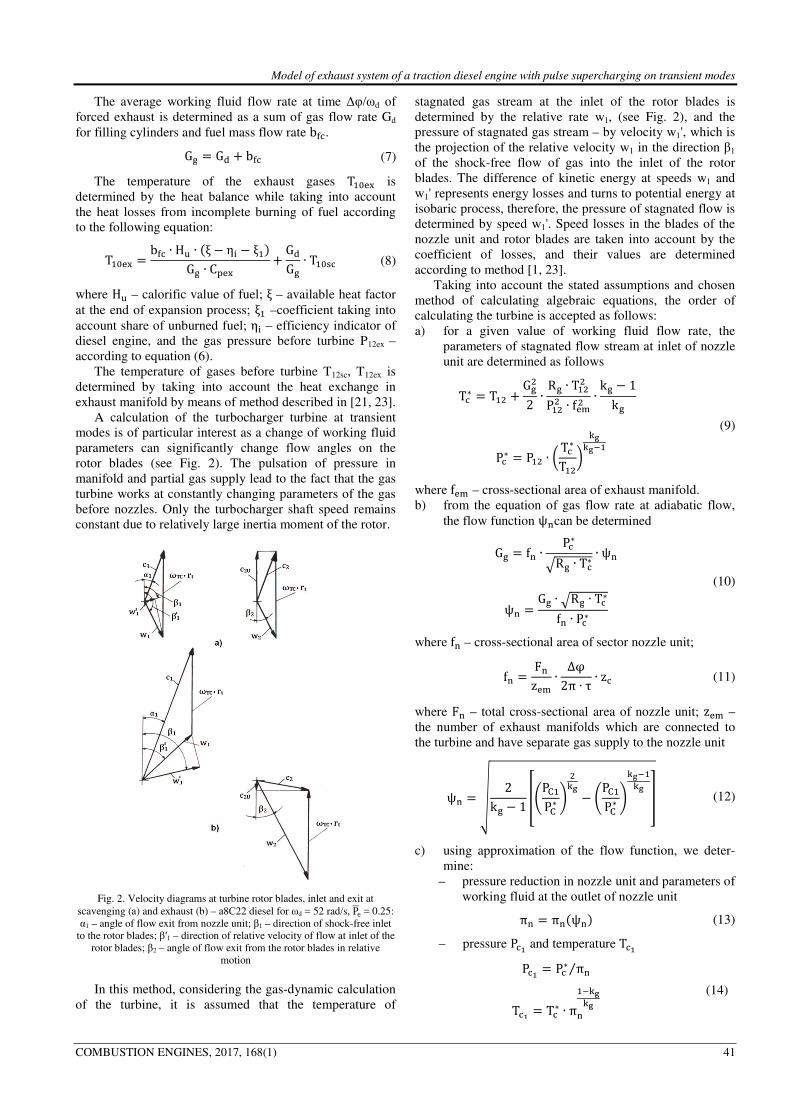
A calculation of the turbocharger turbine at transient modes is of particular interest as a change of working fluid parameters can significantly change flow angles on the rotor blades (see Fig. 2). The pulsation of pressure in manifold and partial gas supply lead to the fact that the gas turbine works at constantly changing parameters of the gas before nozzles. Only the turbocharger shaft speed remains constant due to relatively large inertia moment of the rotor.
Fig. 2. Velocity diagrams at turbine rotor blades, inlet and exit at
scavenging (а) and exhaust (b) – а8С22 diesel for ωd = 52 rad/s, P<е= 0.25: α1 – angle of flow exit from nozzle unit; β1 – direction of shock-free inlet
to the rotor blades; β′1 – direction of relative velocity of flow at inlet of the rotor blades; β2 – angle of flow exit from the rotor blades in relative
motion In this method, considering the gas-dynamic calculation
of the turbine, it is assumed that the temperature of
stagnated gas stream at the inlet of the rotor blades is determined by the relative rate w1, (see Fig. 2), and the pressure of stagnated gas stream – by velocity w1', which is the projection of the relative velocity w1 in the direction β1 of the shock-free flow of gas into the inlet of the rotor blades. The difference of kinetic energy at speeds w1 and w1' represents energy losses and turns to potential energy at isobaric process, therefore, the pressure of stagnated flow is determined by speed w1'. Speed losses in the blades of the nozzle unit and rotor blades are taken into account by the coefficient of losses, and their values are determined according to method [1, 23].
Taking into account the stated assumptions and chosen method of calculating algebraic equations, the order of calculating the turbine is accepted as follows: a) for a given value of working fluid flow rate, the
parameters of stagnated flow stream at inlet of nozzle unit are determined as follows T�∗ � T�3 � G)32 ∙ R) ∙ T�33P�33 ∙ f*@3 ∙ k) % 1k)
(9) P�∗ � P�3 ∙ B T�∗T�3C DEDE/�
where f*@ – cross-sectional area of exhaust manifold. b) from the equation of gas flow rate at adiabatic flow,
the flow function ψGcan be determined G) � fG ∙ P�∗HR) ∙ Т�∗ ∙ ψG
(10) ψG � G) ∙ HR) ∙ T�∗fG ∙ P�∗
where fG – cross-sectional area of sector nozzle unit; fG � FGz*@ ∙ ∆φ2π ∙ τ ∙ z� (11)
where FG – total cross-sectional area of nozzle unit; z*@ – the number of exhaust manifolds which are connected to the turbine and have separate gas supply to the nozzle unit
ψG � M 2k) % 1 NOPP�PP∗ Q 3DE % OPP�PP∗ QDE/�DE R (12)
c) using approximation of the flow function, we deter-mine:
– pressure reduction in nozzle unit and parameters of working fluid at the outlet of nozzle unit πG � πG�ψG� (13)
– pressure P�S and temperature T�S P�S � P�∗ πG⁄
T�S � T�∗ ∙ πG�/DEDE
(14)
Model of exhaust system of a traction diesel engine with pulse supercharging on transient modes
42 COMBUSTION ENGINES, 2017, 168(1)
– absolute с1 and relative w1 flow velocities c� � φ� ∙ G) ∙ R) ∙ T�SfG ∙ P�S , w� � Vc�3 � �ωWP ∙ rY�3 % 2с� ∙ ωWP ∙ rY ∙ cosα�, (15)
where φ1 – the speed loss coefficient in nozzle unit – relative gas velocity w1' by the shock-free inlet and
parameters of stagnation at the inlet of rotor blades β� � π 2⁄ % arcsin Bc� ∙ cosα� % ωWP ∙ rYw� C, w� � w� ∙ cos�β� % β��, T`S∗ � T�S � w�32 ∙ k) % 1k) ∙ R)/�, T̀ Sa∗ � T�S � w�b2 ∙ k) % 1k) ∙ R)/�, P̀ S∗ � P�� ∙ OT̀ Sa∗TPSQDE -DE/�0⁄
(16)
d) based on parameters of stagnation at inlet of rotor blades, we determine flow function ψY, turbine pressure ratio πY, parameters of working fluid at the outlet of rotor blades, relative velocity of gas exhaust from rotor blades w2 and components of absolute velocity c2
ψY � G) ∙ HR) ∙ T̀ S∗fY ∙ P̀ S∗ , (17)
where fY – cross-sectional area of sector rotor blades. πY � πY�ψY�, P̀ b � P̀ S∗ /πY, T`b � T`S∗ ∙ πYSdeEeE , w3 � φ3 ∙ G) ∙ R) ∙ T̀ bfY ∙ P̀ b , (18)
C37 � w3 ∙ cosβ3 % ωWP ∙ rY, C3о � w3 ∙ cos�π % β3�, C3 � HC373 � C3g3 ,
(19)
where φ2 – speed loss coefficient in the rotor blades. e) with the Euler`s formula, we determine specific work
on the rotor blades Li�, adiabatic heat drop Ht and internal efficiency of the turbine ηt Li� � ωWP ∙ rY ∙ -w� ∙ cosβ� %w3 ∙ cos�π % β3�0, HY � DEDE/� ∙ R) ∙ T�3 ∙ O1 % �πG ∙ πY�SdeEeE Q , ηY � Li� HY⁄ . (20)
Exhaust temperature and pressure at the outlet of turbine are calculated from the equation: T�g � T`b � c3732 ∙ k) % 1k) ∙ R)/�, P�g � P̀ b
(21)
A calculation of the exhaust tract and turbine parameters during a forced exhaust was performed by determining the work fluid flow rate throughout the engine, described in the [21].
From a calculation of exhaust process, the average working fluid flow rate in period Δφ is known, and by means of that calculation we determine pressure P��*+ in the manifold 5 (see Fig. 1c).
As a first step of calculation, we set starting value of pressure P��*+k in the first approximation. With equation (8), we can determine a value of temperature Т��*+k and calculate parameters of exhaust tract and turbine; as a result we receive values of pressure reduction in the conditional diaphragm π��, nozzle unit πG, rotor bladesπY, and silencer π�:l. Then, we calculate a product of pressure reductions of working fluid at P��*+,k Т��*+k :
mπ: � P��*+kPiY@ ∙ 1π�� ∙ πG ∙ πY ∙ π�:lG� , (22)
and we check the condition
nmπ: % 1G� n < ε3, (23)
If the condition (23) is not met with a given accuracy of calculations ε3, we set a new value of the current value of pressure P��*+k and repeat the calculation.Otherwise, the average value of pressure P��*+ in period Δφ is the value searched.
An average value of the exhaust gas flow rate throughout the engine can be calculated from relation
G) �p z�2π ∙ τ:qG:q� ∙ ∆φ: ∙ G):, (24)
where n – number of periods Δφ. After the calculation of the inlet system, piston part and
exhaust system of diesel, we solve the system of equations which describes the diesel generator fuel supply and power control at transient processes. The system of equations includes a differential equation of power balance and systems of algebraic equations for the determination of the dependence of diesel generator power and limiting parameters of operational process of the diesel on an angular velocity of the diesel crankshaft. The mathematic model simulates functional connections used in control systems of angular velocity of the crankshaft and power of a diesel locomotive engine [3, 4, 21]. A calculation of transient and steady modes of diesel operation is carried out using a program, common for any diesel type. A general block diagram of that program is represented in Fig. 3.

Model of exhaust system of a traction diesel engine with pulse supercharging on transient modes
COMBUSTION ENGINES, 2017, 168(1) 43
Fig. 3. Block diagram of calculation algorithm of transient process for diesels with pulse supercharging
The diesel operation mode and specific data are entered
into the program in block 1 as an array of source data: array of constants, array of constants of the diesel engine and approximate experimental relations, like efficiency of diesel, characteristics of turbocharger compressors and turbines, etc.
In blocks 2–9, the calculation of air-gas mixture flow rate, Gag, at set values of angular velocities of the diesel crankshaft and turbocharger rotor, temperatures and fuel supply is performed by means of system of nonlinear algebraic equations.
In blocks 10–14, the calculation of exhaust tract and turbine during the time of free exhaust is performed by means of system of nonlinear algebraic equations.
In block 15, a choice of possible increment of fuel consumption is performed according to system of differential and algebraic equations describing specific features of fuel feeding and load control system.
In block 16, an integration of differential equations describing changes the above-mentioned set values in time is done.
In blocks 17–19, actual values of angular velocity of crankshaft ω�, effective power of diesel P*and fuel mass flow rate b5� are compared with the set ones ω�∗ ,P*∗, b5�∗ . In the case of their compliance with given accuracy, the transient process is considered to be finished. Otherwise, the calculation is continued with new values ω� and ωТС, starting from block 3.
In block 21, a print of output parameters is made and the calculation ends.
3. Validation of a diesel engine model Using the demonstrated block diagram and method
described in [21, 23], the performance calculation program of diesel locomotive engine with pulse supercharging on transient mode was made and debugged.
Before using the mathematic model for a calculation of transient modes of diesel engines, compliance of the model with the real objects on steady modes of operation was checked. To this purpose, the results of the numerical calculations were compared with the experimental data from the producer of the engines, HCP Cegielski, for exploitation and load characteristics of the a8C22W traction engines with the pulse turbine supply. Comparison of the calculations with the results of the experimental research showed a sufficient similarity of the results [2, 21]. The discrepancy between the calculated and experimental values is not greater than 2–4%. The differences occurring in the angular velocity of the turbocharger rotor, turbocharging pressure and air low rate under low load can be explained mainly by the shortage of experimental data of compressor (characteristics) within lower angular velocities of the turbocharger.
The evaluation of a mathematic model suitability at transient process was made by comparing operational indices of diesel obtained experimentally on the water braking resistor at rapid increase in the engine loading – switching of the driver controller from IV to XI position, to the numerical calculation data. Figure 4 presents a com-parison of calculated and experimental time characteristics of the transient processes of an a8C22W diesel-generator unit for controlling revolutions and load realized on a SM31 diesel locomotive [2]. Figure 4 proves the sufficient

Model of exhaust system of a traction diesel engine with pulse supercharging on transient modes
44 COMBUSTION ENGINES, 2017, 168(1)
similarity of the results of simulation calculations to the results of experimental research. The greatest deviation of the calculated values is observed for the turbocharging pressure index between 4 and 6 second of the transient process period and is equal to 6%. The discrepancy between
Fig. 4. Time characteristics of transient process in a8С22W diesel-generator unit: ωd, ωTC – angular velocity of crankshaft and turbine rotor; Рs – pressure of charge air; gfc – fuel charge per cycle; Рe – effective power
of diesel; continuous line – experimental data; dashed line – calculated data
the calculated and experimental values for the other performance rates of the diesel engine is not greater than 3%. These results allow the conclusion that the mathematical model reliably reflects the performance rate of the diesel locomotive traction engine both in quality and quantity. Summing up, the developed model can be implemented in optimization calculations of locomotive systems.
4. Conclusion The developed mathematical models of interaction
between the diesel traction engine and turbocharger supplied at variable pressure (including the authors’ models), using the experimental pulse indices, provide a sufficient similarity of the numerical calculations to the experimental results in steady modes of the engine operation. In contrast, in transients modes the satisfactory similarity cannot be obtained. Inclusion of calculations of gas exchange processes into the models using differential equations or implementation of 1-dimension models, e.g. in the case of a turbocharger, makes the mathematical model complicated and unsuitable for optimizing calculations of locomotive systems.
The model of the exhaust system of the diesel traction engine with the pulsating supply of the turbocharger presented in this article was developed by the authors on the basis of a non-linear algebraic equations without the use of differential equations of the charge exchange process and gas exhaust, as well as of experimental, correction coefficients taking into account the pressure pulse of the exhaust gases. The assumption made by the authors for the development of the model are its specific features in comparison with existing methods of modelling of the exhaust systems of diesel traction engines. Confirmation of the validity of the adopted modelling assumptions is obtaining a satisfactory similarity of the results of numerical calculations to the actual runs, both in steady and transition stages. Moreover, the developed mathematical model gains compactness and versatility in terms of description of the processes in various types of traction engines and power aggregates.
The model of the traction engine exhaust constitutes an integral part of the complex model of the diesel locomotive power unit in steady operation and transient stages in exploitation [1, 3]. The complex model was used in the scientific-research works for simulation tests of influence of the power unit loading control on the energy efficiency of the power transmission. These research was aimed at evaluation of the modernisation effectiveness of the power unit loading control of diesel locomotive series SM31 [3, 4].
Bibliography
[1] BABEL, М. Повышение эффективности работы тепло-возных дизелей а8С22 согласованием характе-ристик нагружения с режимами эксплуатации. Dissertation, Moscow, MIIT, 1989. m8.mech.pk.edu.pl/dissertation_babel/ DR_Babel_spis_tresci.pdf
[2] BABEL, M. Zwiększenie efektywności pracy lokomotyw spalinowych SM31 w eksploatacji. TTS Technika Transportu
Szynowego. 2012, 1-2, 41-44. [3] BABEL, M. Теоретические основы и методология
выбора объемов и технологий модернизации тепловозов по критерию стоимости жизненного цикла. Dissertation, Moscow, VNIIZhT, 2014, www.vniizht.ru/fileadmin/ site/files/Babel_doktorska_dissertacia.pdf.
[4] BABEL, M., SZKODA, M. Diesel locomotive efficiency and reliability improvement as a result of power unit load control system modernisation. Eksploatacja i Niezawodność – Maintenance and Reliability. 2016, 18(1), 38-49.
[5] BELLIS, V., MARELLI, S., BOZZA, F., CAPOBIANCO, M. 1D simulation and experimental analysis of a tur-bocharger turbine for automotive engines under steady and unsteady flow conditions. Energy Procedia. 2014, 45, 909-918.
[6] BERGLUND, S.A. Model of turbocharged engines as dynamic drivetrain members. SAE Technical Paper. 1993, 933050.
[7] BIANCHI, G.M., FALFARI, S., PAROTTO, M., OSBAT, G. Advanced modelling of common rail injector dynamics and comparison with experiments. SAE Technical Paper. 2003-01-0006.
[8] ВОЛОДИН, А.И. Моделирование на ЭВМ работы тепловозных дизелей. Москва, Транспорт. 1985, 217c.
[9] CHEN, H., HAKEEM, I., MARTINEZ-BOTAS, R.F. Modelling of a turbocharger turbine under pulsating inlet conditions. Proceedings of the Institutionof Mechanical

Model of exhaust system of a traction diesel engine with pulse supercharging on transient modes
COMBUSTION ENGINES, 2017, 168(1) 45
Engineers, Part A: Journal of Power and Energy. 1996, 210, 397-408.
[10] CHIONG, M.S., RAJOO, S., ROMAGNOLI, A., COSTALL, A.W., MARTINEZ-BOTAS, R.F. Integration of meanline and one-dimensional methods for prediction of pulsating performance of a turbocharger turbine. Energy
Conversion and Management. 2014, 81, 270-281. [11] CHIONG, M.S, PADZILLAH, M.H, RAJOO, S.,
ROMAGNOLI, A., COSTALL, A.W., MARTINEZ-BOTAS, R.F. Comparison of experimental, 3D and 1D model for a mixed-flow turbine under pulsating flow conditions. Jurnal Teknologi. 2015, 77, 61-68.
[12] CHŁOPEK, Z. Modelowanie procesów emisji spalin w warunkach eksploatacji trakcyjnej silników spalinowych. Prace Naukowe Seria „Mechanika”. 1999, z. 173, Oficyna Wydawnicza Politechniki Warszawskiej, Warszawa.
[13] CHŁOPEK, Z., PIASECZNY, L. Uwagi o modelowaniu w badaniach naukowych. Eksploatacja i Niezawodność –
Maintenance and Reliability. 2001, 4(11), 47-57. [14] DANILECKI, K. Założenia do modelowania turbosprężarki
trakcyjnego silnika z pulsacyjnym zasilaniem turbiny. Archiwum Motoryzacji. 2006, 4, 421-436.
[15] DANILECKI, K. Model systemu turbodoładowania trakcyjnego silnika o zapłonie samoczynnym. Silniki
spalinowe. 2007, 3(130), 36-48. [16] FERENC, N. Modelowanie numeryczne procesu regulacji
okrętowego silnika wysokoprężnego z uwzględnieniem nieliniowości. Zeszyty naukowe Politechniki Śląskiej. 1978, 567.
[17] GALINDO, J., FAJARDO, P., NAVARRO, R., GARCA-CUEVAS, L.M. Characterization of a radial turbocharger turbine in pulsating ow by means of CFD and its application to engine modelling. Applied Energy. 2013, 103, 116-127.
[18] GUZZELLA, L., ONDER, CH. Introduction to modelling and control of internal combustion engine systems. Springer
Verlag. 2nd Ed., 2010. [19] IKEYA, N., YAMAGUCHI, H., MITSUBORI, K.,
KONDOH, N. Development of advanced model of turbocharger for automotive engines. SAE Technical Paper. 1992, 1992-02- 920047.
[20] KESSEL, J.A., SCHMIDT, M., SCHAFFNIT, J. Modeling and real-time simulation of a turbocharger with variable turbine geometry (Vtg). SAE Technical Paper. 1998, 1998-02-980770.
[21] KOSSOV, E., BABEL, M. Zagadnienia modelowania eksploatacyjnych warunków pracy trakcyjnych silników spalinowych. Silniki Spalinowe. 1988, 2, 27-31, m8.mech. pk.edu.pl/articles/Artykul_SS_1988.pdf.
[22] KOWALSKI, J. Model procesu spalania w 4-suwowym silniku okrętowym. Mechanik. 2015, 10, 49-58.
[23] КОССОВ, Е.Е., CУХОПАРОВ, С.И. Оптимизация режимов работы тепловозных дизель- генераторов. Труды ВНИИЖТ. Интекст. 1999, 184 с.
[24] MA, H., XU, H., WANG, J. Real-time control oriented HCCI engine cycle-to cycle dynamic modelling. Inter-
national Journal of Automation and Computing. 2011, 8(3), 317-325.
[25] MACEK, J., VÁVRA, J., VÍTEK, O. 1-D Model of radial turbocharger turbine calibrated by experiments. SAE
Technical Paper. 2002, 2002-01-0377.
[26] MARECKA-CHŁOPEK, E., CHŁOPEK, Z. Badania porównawcze emisji zanieczyszczeń z silników spalinowych o różnych zastosowaniach. Transport samochodowy. 2009, 9,71-84.
[27] NIEWIAROWSKI, K. Tłokowe silniki spalinowe. Tom II. WKŁ. 1983. Warszawa.
[28] PANCHAREVSKI, G., IVANOV, V. Bestimmung der wärmeverluste in diffusor eines turbokompressors. IV
Symposium Klimatechnik, Belüftung Wärmeaustausch in
Transportwesen – Tagungsmaterialen. Politechnika Szczecińska. 1992.
[29] RAKOPOULOS, C.D., GIAKOUMIS, E.G. Review of thermodynamic diesel engine simulations under transient operating conditions. 2006, citeseerx.ist.psu.edu/view-doc/download?doi=10.1.1.466.5353&rep=rep1 & type=pdf.
[30] RYCHTER, T., TEODORCZYK, A. Teoria silników tłokowych. WKŁ. 2006, Warszawa.
[31] RYCHTER, T., TEODORCZYK, A. Modelowanie mate-matyczne roboczego cyklu silnika tłokowego. PWN. 1990, Warszawa.
[32] SERRANO, J.R., REYES, E., PAYRI, F. A Model for load transients of turbocharged diesel engines. SAE Technical
Paper. 1999, 1999-01-0225. [33] SERRANO, J.R., ARNAU, F.J., PIQUERAS, P.,
ONORATI, A., MONTENEGRO, G. 1D gas dynamic modelling of mass conservation in engine duct systems with thermal contact discontinuities. Mathematical and Computer
Modelling. 2009, 49, 1078-1088. [34] SIGURDSSON, E., INGVORSEN, K.M., JENSEN, M.V,
MAYER, S. Numerical analysis of the scavenge flow and convective heat transfer in large two-stroke marine diesel engines. Applied Energy. 2014, 123, 37-46.
[35] SOBIESZAŃSKI, M. Modelowanie procesów zasilania w silnikach spalinowych. WKŁ. 2000, Warszawa.
[36] TUTAK, W. Modelowanie obiegu cieplnego tłokowego silnika spalinowego o zapłonie samoczynnym. Modelowanie
inżynierskie. 2013, 49, 73-78. [37] ТИМАНОВСКАЯ, Л.К, СОБОЛЬ, В.Н., ПОГРЕБНЯК,
В.В. Моделирование переходных процессов дизеля со свободным турбокомпрессором. Двигатели внутреннего
сгорания. Издание ХГУ. 1975, вып. 21, 53-58. [38] WATSON, N. Transient performance simulation and
analysis of turbocharged diesel engines. SAE Technical
Paper. 1981, 810338. [39] WENDEKER, M., GODULA, A. Research on variability in
control parameters for spark ignition engines in real-life operation. Eksploatacja i Niezawodność – Maintenance and
Reliability. 2002, 16(4), 12-23. [40] WISŁOCKI, K. Badanie wpływu upustowej regulacji
parametrów doładowania na własności trakcyjne turbodoładowanych silników spalinowych. Dysertacja, Wydawnictwo Politechniki Poznańskiej. 1986.
[41] ZELLBECK, H., WOSCHNI, G. Rechnerische Unter-suchung des dynamischen Betriebsverhaltens aufgeladener Dieselmotor. MTZ. 1983, 3, 81-86.
[42] ZINNER, K. Aufladung von Verbrennungsmotoren – Наддув двигателей внутреннего сгорания. Перевод с немецкого. Под редакцией Н.Н. Иванченко. Ленинград,
Машиностроение. 1978.
Marek Babel, DSc., DEng. – Faculty of Mechanical Engineering, Institute of Rail Vehicles, Cracow University of Technology.
e-mail: [email protected]
Evgeni Kossov, DSc., DEng. – Joint Stock Company Railway Research Institute, Moscow, Russia.
e-mail: [email protected]