model no. wv-q116e deutsch -...
TRANSCRIPT
PREFACE
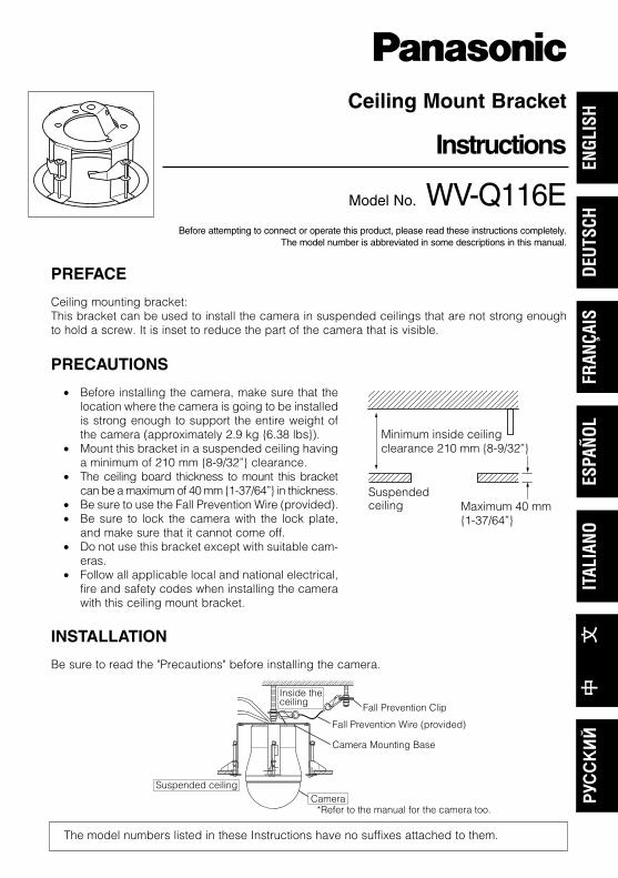
Ceiling mounting bracket: This bracket can be used to install the camera in suspended ceilings that are not strong enoughto hold a screw. It is inset to reduce the part of the camera that is visible.
Ceiling Mount Bracket
Instructions
Model No. WV-Q116EBefore attempting to connect or operate this product, please read these instructions completely.
The model number is abbreviated in some descriptions in this manual.
PRECAUTIONS
• Before installing the camera, make sure that thelocation where the camera is going to be installedis strong enough to support the entire weight ofthe camera (approximately 2.9 kg {6.38 lbs}).
• Mount this bracket in a suspended ceiling havinga minimum of 210 mm {8-9/32”} clearance.
• The ceiling board thickness to mount this bracketcan be a maximum of 40 mm {1-37/64”} in thickness.
• Be sure to use the Fall Prevention Wire (provided).• Be sure to lock the camera with the lock plate,
and make sure that it cannot come off. • Do not use this bracket except with suitable cam-
eras. • Follow all applicable local and national electrical,
fire and safety codes when installing the camerawith this ceiling mount bracket.
Minimum inside ceilingclearance 210 mm {8-9/32”}
Suspendedceiling Maximum 40 mm
{1-37/64”}
The model numbers listed in these Instructions have no suffixes attached to them.
*Refer to the manual for the camera too.
Inside the ceiling
Suspended ceiling
Camera Mounting Base
Fall Prevention Clip
Fall Prevention Wire (provided)
Camera
INSTALLATION
Be sure to read the "Precautions" before installing the camera.
ENGL
ISH
FRAN
ÇAIS
DEUT
SCH
ESPA
ÑOL
ITAL
IANO
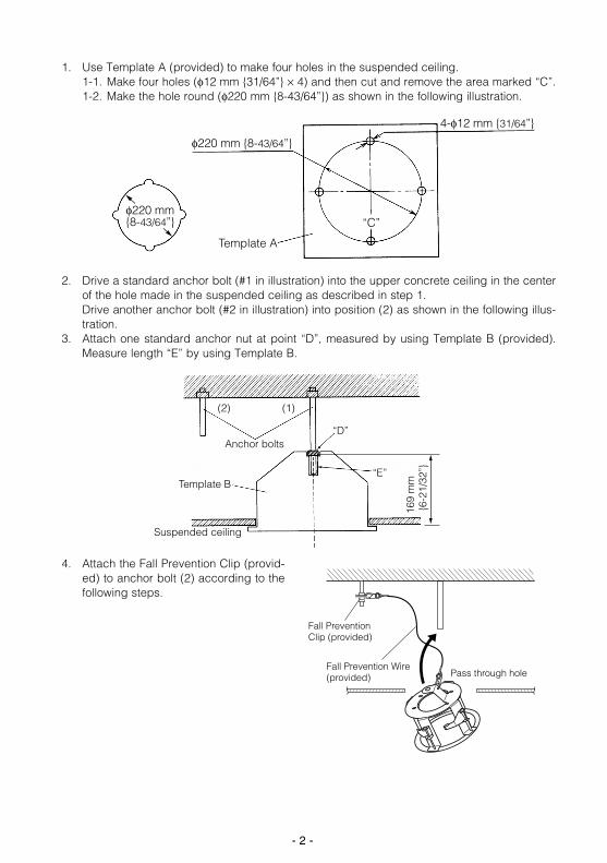
2. Drive a standard anchor bolt (#1 in illustration) into the upper concrete ceiling in the centerof the hole made in the suspended ceiling as described in step 1. Drive another anchor bolt (#2 in illustration) into position (2) as shown in the following illus-tration.
3. Attach one standard anchor nut at point “D”, measured by using Template B (provided).Measure length “E” by using Template B.
- 2 -
1. Use Template A (provided) to make four holes in the suspended ceiling.1-1. Make four holes (φ12 mm {31/64”} × 4) and then cut and remove the area marked “C”.1-2. Make the hole round (φ220 mm {8-43/64”}) as shown in the following illustration.
φ220 mm {8-43/64”}
Template A
4-φ12 mm {31/64”}
φ220 mm {8-43/64”} “C”
(2) (1)
Template B
Anchor bolts
Suspended ceiling
“D”
“E”
169
mm
{6-
21/3
2”}
4. Attach the Fall Prevention Clip (provid-ed) to anchor bolt (2) according to thefollowing steps.
Pass through hole
Fall Prevention Clip (provided)
Fall Prevention Wire(provided)
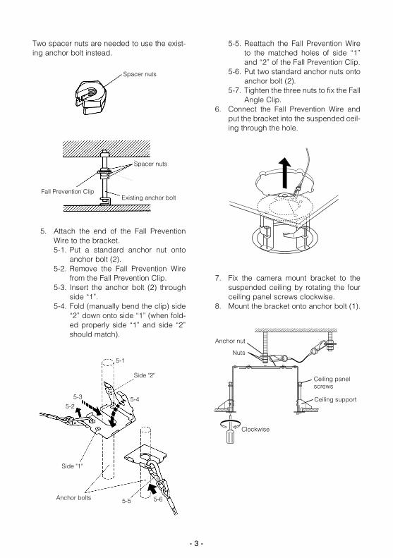
Two spacer nuts are needed to use the exist-ing anchor bolt instead.
5. Attach the end of the Fall PreventionWire to the bracket.5-1. Put a standard anchor nut onto
anchor bolt (2).5-2. Remove the Fall Prevention Wire
from the Fall Prevention Clip.5-3. Insert the anchor bolt (2) through
side “1”.5-4. Fold (manually bend the clip) side
“2” down onto side “1” (when fold-ed properly side “1” and side “2”should match).
5-5. Reattach the Fall Prevention Wireto the matched holes of side “1”and “2” of the Fall Prevention Clip.
5-6. Put two standard anchor nuts ontoanchor bolt (2).
5-7. Tighten the three nuts to fix the FallAngle Clip.
6. Connect the Fall Prevention Wire andput the bracket into the suspended ceil-ing through the hole.
7. Fix the camera mount bracket to thesuspended ceiling by rotating the fourceiling panel screws clockwise.
8. Mount the bracket onto anchor bolt (1).
- 3 -
5-1
5-3
5-25-4
5-5 5-6
Side "1"
Anchor bolts
Side "2"
Existing anchor bolt
Spacer nuts
Spacer nuts
Fall Prevention Clip
Ceiling support
Clockwise
Anchor nut
Nuts
Ceiling panel screws
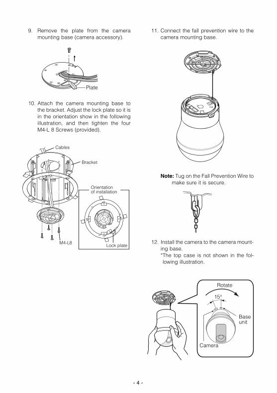
9. Remove the plate from the cameramounting base (camera accessory).
10. Attach the camera mounting base tothe bracket. Adjust the lock plate so it isin the orientation show in the followingillustration, and then tighten the fourM4-L 8 Screws (provided).
11. Connect the fall prevention wire to thecamera mounting base.
Note: Tug on the Fall Prevention Wire tomake sure it is secure.
12. Install the camera to the camera mount-ing base. *The top case is not shown in the fol-lowing illustration.
- 4 -
Plate
Cables
Orientation of installation
Lock plateM4-L8
Bracket
15°
Rotate
Camera
Base unit
- 5 -
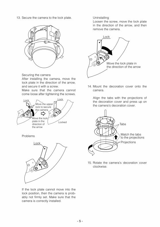
13. Secure the camera to the lock plate.
Securing the cameraAfter installing the camera, move thelock plate in the direction of the arrow,and secure it with a screw. Make sure that the camera cannotcome loose after tightening the screws.
Problems
If the lock plate cannot move into thelock position, then the camera is prob-ably not firmly set. Make sure that thecamera is correctly installed.
Uninstalling Loosen the screw, move the lock platein the direction of the arrow, and thenremove the camera.
14. Mount the decoration cover onto thecamera.
Align the tabs with the projections ofthe decoration cover and press up onthe camera’s decoration cover.
15. Rotate the camera’s decoration coverclockwise.
Lock
Lock
Lock
Locked
LockMove the upper lock to secure the camera
Move the lock plate in the direction of the arrow
Lock
Lock
Lock
Move the lock plate in the direction of the arrow
Lock
Tabs
Match the tabsto the projections
Projections
- 6 -
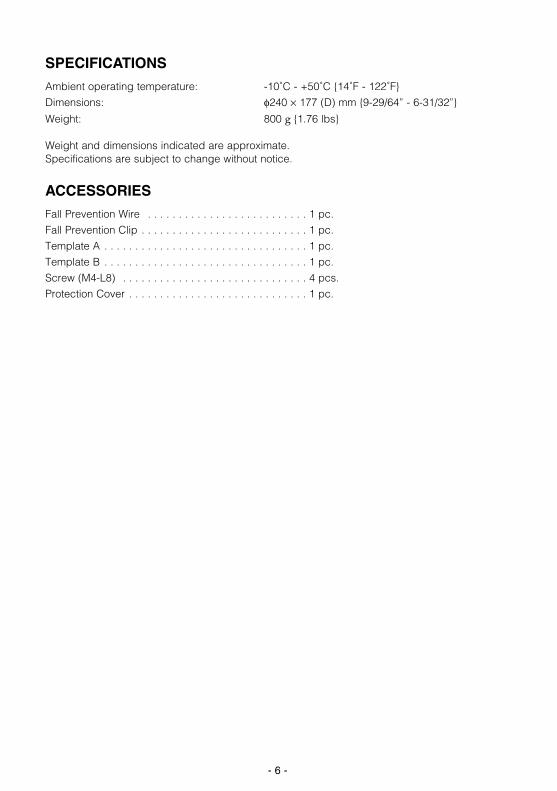
SPECIFICATIONS
Ambient operating temperature: -10˚C - +50˚C {14˚F - 122˚F}
Dimensions: φ240 × 177 (D) mm {9-29/64” - 6-31/32”}
Weight: 800 g {1.76 lbs}
Weight and dimensions indicated are approximate.Specifications are subject to change without notice.
ACCESSORIES
Fall Prevention Wire . . . . . . . . . . . . . . . . . . . . . . . . . . 1 pc.
Fall Prevention Clip . . . . . . . . . . . . . . . . . . . . . . . . . . . 1 pc.
Template A . . . . . . . . . . . . . . . . . . . . . . . . . . . . . . . . . 1 pc.
Template B . . . . . . . . . . . . . . . . . . . . . . . . . . . . . . . . . 1 pc.
Screw (M4-L8) . . . . . . . . . . . . . . . . . . . . . . . . . . . . . . 4 pcs.
Protection Cover . . . . . . . . . . . . . . . . . . . . . . . . . . . . . 1 pc.
- 7 -
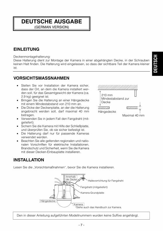
EINLEITUNG
Deckenmontagehalterung: Diese Halterung dient zur Montage der Kamera in einer abgehängten Decke, in der Schraubenkeinen Halt finden. Die Halterung wird eingelassen, so dass der sichtbare Teil der Kamera kleinerist.
VORSICHTSMASSNAHMEN
• Stellen Sie vor Installation der Kamera sicher,dass der Ort, an dem die Kamera installiert wer-den soll, für das Gesamtgewicht der Kamera (ca.2,9 kg) geeignet ist.
• Bringen Sie die Halterung an einer Hängedeckemit einem Mindestabstand von 210 mm an.
• Die Dicke der Deckenplatte, an der die Halterungangebracht werden soll, darf maximal 40 mmbetragen.
• Verwenden Sie in jedem Fall den Fangdraht (mit-geliefert).
• Sichern Sie die Kamera mit Hilfe der Schließplatte,und überprüfen Sie, ob sie sicher befestigt ist.
• Die Halterung darf nur für passende Kamerasverwendet werden.
• Beachten Sie alle geltenden regionalen und natio-nalen Vorschriften für elektrische Installationen,Brandschutz und Sicherheit, wenn Sie die Kameramit dieser Decken-Einbauplatte installieren.
210 mm Mindestabstand zur Decke
HängedeckeMaximal 40 mm
Den in dieser Anleitung aufgeführten Modellnummern wurden keine Suffixe angehängt.
*Siehe auch das Handbuch zur Kamera.
Innerhalb der Decke
Hängedecke
Kamera-Grundplatte
Haltevorrichtung für Fangdraht
Fangdraht (mitgeliefert)
Kamera
INSTALLATION
Lesen Sie die „Vorsichtsmaßnahmen“, bevor Sie die Kamera installieren.
DEUTSCHE AUSGABE(GERMAN VERSION)
DEUT
SCH
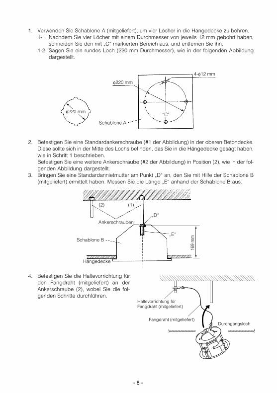
2. Befestigen Sie eine Standardankerschraube (#1 der Abbildung) in der oberen Betondecke.Diese sollte sich in der Mitte des Lochs befinden, das Sie in die Hängedecke gesägt haben,wie in Schritt 1 beschrieben. Befestigen Sie eine weitere Ankerschraube (#2 der Abbildung) in Position (2), wie in der fol-genden Abbildung dargestellt.
3. Bringen Sie eine Standardannietmutter am Punkt „D“ an, den Sie mit Hilfe der Schablone B(mitgeliefert) ermittelt haben. Messen Sie die Länge „E“ anhand der Schablone B aus.
- 8 -
1. Verwenden Sie Schablone A (mitgeliefert), um vier Löcher in die Hängedecke zu bohren. 1-1. Nachdem Sie vier Löcher mit einem Durchmesser von jeweils 12 mm gebohrt haben,
schneiden Sie den mit „C“ markierten Bereich aus, und entfernen Sie ihn. 1-2. Sägen Sie ein rundes Loch (220 mm Durchmesser), wie in der folgenden Abbildung
dargestellt.
φ220 mm
Schablone A
4-φ12 mm
φ220 mm“C”
(2) (1)
Ankerschrauben
Schablone B
Hängedecke
„D“
„E“
169
mm
4. Befestigen Sie die Haltevorrichtung fürden Fangdraht (mitgeliefert) an derAnkerschraube (2), wobei Sie die fol-genden Schritte durchführen.
Durchgangsloch
Haltevorrichtung für Fangdraht (mitgeliefert)
Fangdraht (mitgeliefert)
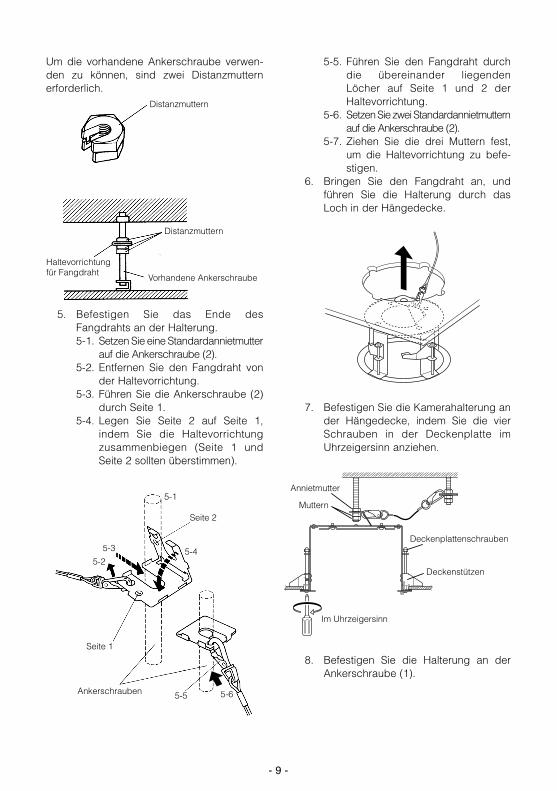
Um die vorhandene Ankerschraube verwen-den zu können, sind zwei Distanzmutternerforderlich.
5. Befestigen Sie das Ende desFangdrahts an der Halterung.5-1. Setzen Sie eine Standardannietmutter
auf die Ankerschraube (2).5-2. Entfernen Sie den Fangdraht von
der Haltevorrichtung.5-3. Führen Sie die Ankerschraube (2)
durch Seite 1.5-4. Legen Sie Seite 2 auf Seite 1,
indem Sie die Haltevorrichtungzusammenbiegen (Seite 1 undSeite 2 sollten überstimmen).
5-5. Führen Sie den Fangdraht durchdie übereinander liegendenLöcher auf Seite 1 und 2 derHaltevorrichtung.
5-6. Setzen Sie zwei Standardannietmutternauf die Ankerschraube (2).
5-7. Ziehen Sie die drei Muttern fest,um die Haltevorrichtung zu befe-stigen.
6. Bringen Sie den Fangdraht an, undführen Sie die Halterung durch dasLoch in der Hängedecke.
7. Befestigen Sie die Kamerahalterung ander Hängedecke, indem Sie die vierSchrauben in der Deckenplatte imUhrzeigersinn anziehen.
8. Befestigen Sie die Halterung an derAnkerschraube (1).
- 9 -
5-1
5-3
5-25-4
5-5 5-6
Seite 1
Ankerschrauben
Seite 2
Vorhandene Ankerschraube
Distanzmuttern
Distanzmuttern
Haltevorrichtung für Fangdraht
Deckenstützen
Im Uhrzeigersinn
Annietmutter
Muttern
Deckenplattenschrauben

9. Trennen Sie die Platte vomKamerasockel (Kamerazubehör).
10. Bringen Sie die Kamera-Grundplatte ander Halterung an. Richten Sie dieSchließplatte der folgenden Abbildungentsprechend aus, und ziehen Sie dievier M4-L8-Schrauben fest (mitgelie-fert).
11. Bringen Sie den Fangdraht an derKamera-Grundplatte an.
Hinweis: Ziehen Sie am Fangdraht, umzu überprüfen, ob dieser sicherbefestigt ist.
12. Bringen Sie die Kamera an derKamera-Grundplatte an. * Der obere Teil des Einsatzes wird in
der folgenden Abbildung nichtgezeigt.
- 10 -
Abdeckung
Kabel
Richtung der Installation
SchließplatteM4-L8
Halterung
15°
Drehrichtung
Kamera
Grundplatte
- 11 -
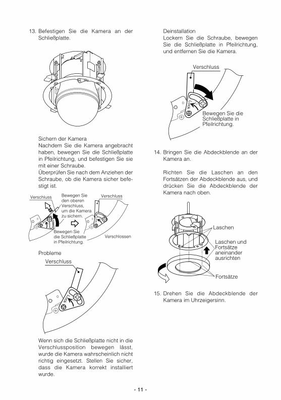
13. Befestigen Sie die Kamera an derSchließplatte.
Sichern der KameraNachdem Sie die Kamera angebrachthaben, bewegen Sie die Schließplattein Pfeilrichtung, und befestigen Sie siemit einer Schraube.Überprüfen Sie nach dem Anziehen derSchraube, ob die Kamera sicher befe-stigt ist.
Probleme
Wenn sich die Schließplatte nicht in dieVerschlussposition bewegen lässt,wurde die Kamera wahrscheinlich nichtrichtig eingesetzt. Stellen Sie sicher,dass die Kamera korrekt installiertwurde.
DeinstallationLockern Sie die Schraube, bewegenSie die Schließplatte in Pfeilrichtung,und entfernen Sie die Kamera.
14. Bringen Sie die Abdeckblende an derKamera an.
Richten Sie die Laschen an denFortsätzen der Abdeckblende aus, unddrücken Sie die Abdeckblende derKamera nach oben.
15. Drehen Sie die Abdeckblende derKamera im Uhrzeigersinn.
Lock
Verschluss
Verschlossen
Verschluss Bewegen Sie den oberen Verschluss, um die Kamera zu sichern.
Lock
Lock
Verschluss
Bewegen Sie die Schließplatte in Pfeilrichtung.
Bewegen Sie die Schließplatte in Pfeilrichtung.
Lock
Verschluss
Laschen
Laschen und Fortsätze aneinander ausrichten
Fortsätze
- 12 -
TECHNISCHE DATEN
Umgebungstemperatur: -10˚C bis +50˚CAbmessungen: φ240 × 177 (D) mmGewicht: 800 g
Bei dem angegebenen Gewicht und den Abmessungen handelt es sich um Näherungswerte.Änderung der technischen Daten ohne Ankündigung vorbehalten.
ZUBEHÖR
Fangdraht . . . . . . . . . . . . . . . . . . . . . . . . . . . . . . . . . . . . . . . . . . . . . . . 1 St.Haltevorrichtung für Fangdraht . . . . . . . . . . . . . . . . . . . . . . . . . . . . . . . 1 St.Schablone A . . . . . . . . . . . . . . . . . . . . . . . . . . . . . . . . . . . . . . . . . . . . . 1 St.Schablone B . . . . . . . . . . . . . . . . . . . . . . . . . . . . . . . . . . . . . . . . . . . . . 1 St.Schrauben (M4-L8) . . . . . . . . . . . . . . . . . . . . . . . . . . . . . . . . . . . . . . . . 4 St.Schutzabdeckung . . . . . . . . . . . . . . . . . . . . . . . . . . . . . . . . . . . . . . . . . 1 St.

- 13 -
PRÉFACE
Support de fixation plafond: Cette fixation peut être utilisée pour installer la caméra vidéo à des faux-plafonds qui ne sont pasassez solides pour supporter une vis. Elle est intercalée pour minimiser la partie de la caméra quiest visible.
MESURES DE PRÉCAUTION
• Avant d’installer la caméra, veiller à ce que l’empla-cement où elle doit être installée soit assez solidepour supporter son poids total (environ 2,9 kg).
• Installer cette potence sur un plafond suspendupossédant un espacement minimum de 210 mm.
• L’épaisseur de la plaque utilisée pour installercette potence au plafond peut être de 40 mm aumaximum.
• Veiller à utiliser le câble de prévention de chute(fourni).
• Veiller à verrouiller la caméra avec la plaque de ver-rouillage et s’assurer qu’elle ne peut se détacher.
• N’utilisez cette fixation qu’avec les caméras adé-quates.
• Lors de l’installation de la caméra avec ce sup-port de fixation au plafond, respectez tous lescodes appropriés, locaux et nationaux, concer-nant l’électricité, l’incendie et la sécurité.
210 mm d’espacement minimum à l’intérieur du plafond
Plafondsuspendu Maximum 40 mm
Les numéros de modèles mentionnés dans ces instructions ne contiennent aucun suffixe.
*Reportez-vous au manuel de la caméra également.
Intérieur du plafond
Plafond suspendu
Base de fixation de la caméra
Attache de cornière du fixation de câble de prévention de chute
Câble de prévention de chute (fourni)
Caméra vidéo
INSTALLATION
Lire attentivement les “Mesures de précaution” avant de commencer à installer la caméra.
VERSION FRANÇAISE(FRENCH VERSION)
FRAN
ÇAIS

2. Engager un boulon d’ancrage (no 1 sur l’illustration) dans le plafond supérieur de béton aumilieu du trou fait dans le plafond suspendu à l’étape 1.Engager un deuxième boulon d’ancrage (no 2 sur l’illustration) dans la position (2) commesur l’illustration suivante.
3. Fixer un ècrou d’ancrage ordinaire au point “D” mesuré à l’aide du gabarit B (fourni).Mesurer la longueur “E” à l’aide du gabarit B.
- 14 -
1. Utiliser le gabarit A (fourni) pour percer quatre trous dans le plafond suspendu. 1-1. Percer quatre trous (φ12 mm × 4) puis découper et retirer la zone “C”.1-2. Arrondir le trou (φ220 mm) comme indiqué sur l’illustration ci-dessous.
φ220 mm
Gabarit A
4-φ12 mm
φ220 mm “C”
(2) (1)
Boulons d’ancrage
Gabarit B
Plafond suspendu
“D”
“E”
169
mm
{6,6
5 po
uses
}
4. Fixer l’attache de cornière de fixationdu câble de prévention de chute (four-nie) au boulon d’ancrage (2) en suivantles étapes suivantes.
Passer à travers le trouCâble de prévention chute (fourni)
Attache de cornière de fixation de câble de prévention de chute(fournie)

Deux écrous d’entretoise sont nécessairespour utiliser plutôt le boulon d’ancrage exis-tant.
5. Fixer l’extrémité du câble de préventionde chute à la potence.5-1. Monter un écrou d’ancrage ordi-
naire sur le boulon d’ancrage (2).5-2. Retirer le câble de prévention de
chute de l’attache de cornière deprévention de chute.
5-3. Insérer le boulon d’ancrage (2) parle côté “1”.
5-4. Replier le côté “2” (courber l’at-tache à la main) sur le côté “1”(une fois correctement pliés, lescôtés “1” et “2” doivent corres-pondre).
5-5. Remettre le câble de préventionde chute dans les trous corres-pondants des côtés “1” et “2” del’attache de cornière de préventionde chute.
5-6. Monter deux écrous d’ancrageordinaires sur le boulon d’ancrage(2).
5-7. Resserrer les trois écrous de façonà bloquer l’attache de cornière deprévention de chute.
6. Connecter le câble de prévention dechute et installer la potence sur le pla-fond suspendu en passant par le trou.
7. Fixer la potence de fixation au plafondsuspendu en faisant tourner les quatrevis de panneau de plafond dans lesens des aiguilles d’une montre.
8. Installer la potence sur le boulon d’an-crage (1).
- 15 -
5-1
5-3
5-25-4
5-5 5-6
Côte “1”
Boulon d’ancrage
Côte “2”
Boulon d’ancrage existant
Écrous d’entretoise
Écrous d’entretoise
Attache de cornière de fixation de câble de prévention de chute
Support de plafond
Sens des aiguilles d’une montre
Écrou d’ancrage
Écrous
Vis de panneau de plafond
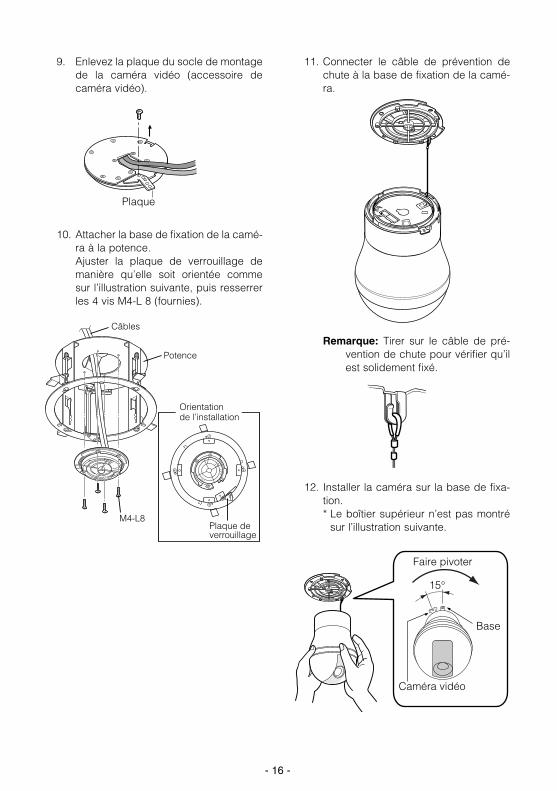
9. Enlevez la plaque du socle de montagede la caméra vidéo (accessoire decaméra vidéo).
10. Attacher la base de fixation de la camé-ra à la potence. Ajuster la plaque de verrouillage demanière qu’elle soit orientée commesur l’illustration suivante, puis resserrerles 4 vis M4-L 8 (fournies).
11. Connecter le câble de prévention dechute à la base de fixation de la camé-ra.
Remarque: Tirer sur le câble de pré-vention de chute pour vérifier qu’ilest solidement fixé.
12. Installer la caméra sur la base de fixa-tion.* Le boîtier supérieur n’est pas montré
sur l’illustration suivante.
- 16 -
Plaque
Câbles
Orientation de l’installation
Plaque de verrouillage
M4-L8
Potence
15°
Faire pivoter
Caméra vidéo
Base
- 17 -
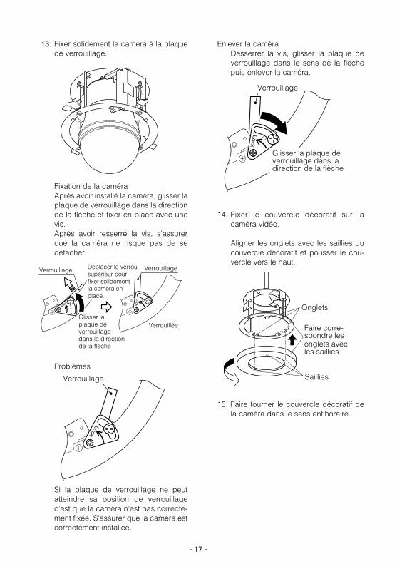
13. Fixer solidement la caméra à la plaquede verrouillage.
Fixation de la caméraAprès avoir installé la caméra, glisser laplaque de verrouillage dans la directionde la flèche et fixer en place avec unevis. Après avoir resserré la vis, s’assurerque la caméra ne risque pas de sedétacher.
Problèmes
Si la plaque de verrouillage ne peutatteindre sa position de verrouillagec’est que la caméra n’est pas correcte-ment fixée. S’assurer que la caméra estcorrectement installée.
Enlever la caméraDesserrer la vis, glisser la plaque deverrouillage dans le sens de la flèchepuis enlever la caméra.
14. Fixer le couvercle décoratif sur lacaméra vidéo.
Aligner les onglets avec les saillies ducouvercle décoratif et pousser le cou-vercle vers le haut.
15. Faire tourner le couvercle décoratif dela caméra dans le sens antihoraire.
Lock
Verrouillage
Verrouillée
Verrouillage Déplacer le verrou supérieur pour fixer solidement la caméra en place.
Glisser la plaque de verrouillage dans la direction de la flèche
LockLock
Verrouillage
Glisser la plaque de verrouillage dans la direction de la flèche
Lock
Verrouillage
Onglets
Faire corre-spondre lesonglets avec les saillies
Saillies
- 18 -
CARACTÉRISTIQUES TECHNIQUES
Température ambiante de fonctionnement: -10˚C - +50˚CDimensions: φ240 × 177 (D) mmPoids: 800 g
Les poids et les dimensions donnés sont approximatifs.Ces caractéristiques peuvent être modifiées sans préavis.
ACCESSOIRES
Câble de prévention de chute . . . . . . . . . . . . . . . . . . . . . . . . . . . . . . . . 1 pièceAttache de cornière de fixation du câble de prévention de chute . . . . . 1 pièceGabarit A . . . . . . . . . . . . . . . . . . . . . . . . . . . . . . . . . . . . . . . . . . . . . . . 1 pièceGabarit B . . . . . . . . . . . . . . . . . . . . . . . . . . . . . . . . . . . . . . . . . . . . . . . 1 pièceVis (M4-L8) . . . . . . . . . . . . . . . . . . . . . . . . . . . . . . . . . . . . . . . . . . . . . . 4 piècesCouvercle de protection . . . . . . . . . . . . . . . . . . . . . . . . . . . . . . . . . . . . 1 pièce

- 19 -
PREFACIO
Ménsula de montaje en el techo: Esta ménsula se puede utilizar para instalar la cámara en falsos techos que no sean suficiente-mente resistentes para retener un tornillo. Esta embutida para reducir la parte de la cámara quequeda visible.
PRECAUCIONES
• Antes de instalar la cámara, compruebe que ellugar donde se va a instalar es suficientementeresistente para soportar el peso total de la cáma-ra (2,9 kg aproximadamente).
• Instale la ménsula en un falso techo que tengaun mínimo de 210 mm de espacio libre.
• El grosor de la placa de techo para instalar estaménsula puede se de un máximo de 40 mm.
• Utilice el cable anticaídas (suministrado).• Bloquee la cámara con la placa de cierre y cer-
ciórese de que no se suelta.• No utilice esta ménsula con cámaras que no
sean las adecuadas. • Observe todas las normas de seguridad, electri-
cidad y de prevención de incendios, tanto nacio-nales como internacionales, a la hora de instalarla cámara con esta ménsula de montaje en eltecho.
Espacio libre mínimo en el interior del techo 210 mm
Falso techo Máximo 40 mm
Los números de modelo que aparecen en estas instrucciones no llevan sufijos.
*Consulte el manual de la cámara también.
Interior del techo
Falso techo
Base de montaje de la cámara
Abrazadera de ángulo anticaídas
Cable anticaídas (suministrado)
Cámara
INSTALACIÓN
Antes de instalar la cámara, lea atentamente las “Precauciones”.
VERSION ESPAÑOLA(SPANISH VERSION)
ESPA
ÑOL
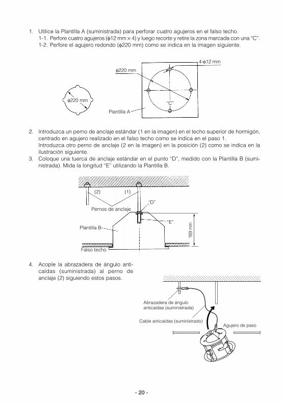
2. Introduzca un perno de anclaje estándar (1 en la imagen) en el techo superior de hormigón,centrado en agujero realizado en el falso techo como se indica en el paso 1.Introduzca otro perno de anclaje (2 en la imagen) en la posición (2) como se indica en lailustración siguiente.
3. Coloque una tuerca de anclaje estándar en el punto “D”, medido con la Plantilla B (sumi-nistrada). Mida la longitud “E” utilizando la Plantilla B.
- 20 -
1. Utilice la Plantilla A (suministrada) para perforar cuatro agujeros en el falso techo. 1-1. Perfore cuatro agujeros (φ12 mm × 4) y luego recorte y retire la zona marcada con una “C”.1-2. Perfore el agujero redondo (φ220 mm) como se indica en la imagen siguiente.
φ220 mm
Plantilla A
4-φ12 mm
φ220 mm“C”
(2) (1)
Pernos de anclaje
Plantilla B
Falso techo
“D”
“E”
169
mm
4. Acople la abrazadera de ángulo anti-caídas (suministrada) al perno deanclaje (2) siguiendo estos pasos.
Agujero de paso
Abrazadera de ángulo anticaídas (suministrada)
Cable anticaídas (suministrado)
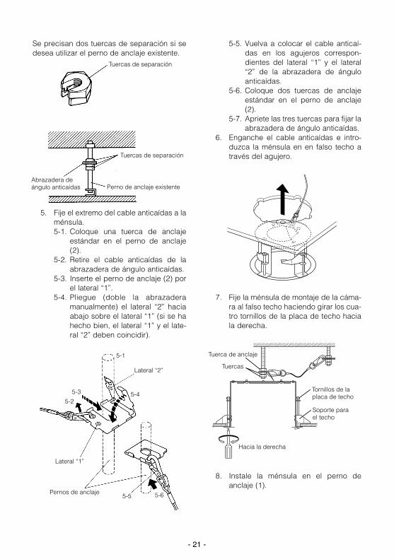
Se precisan dos tuercas de separación si sedesea utilizar el perno de anclaje existente.
5. Fije el extremo del cable anticaídas a laménsula.5-1. Coloque una tuerca de anclaje
estándar en el perno de anclaje(2).
5-2. Retire el cable anticaídas de laabrazadera de ángulo anticaídas.
5-3. Inserte el perno de anclaje (2) porel lateral “1”.
5-4. Pliegue (doble la abrazaderamanualmente) el lateral “2” haciaabajo sobre el lateral “1” (si se hahecho bien, el lateral “1” y el late-ral “2” deben coincidir).
5-5. Vuelva a colocar el cable anticaí-das en los agujeros correspon-dientes del lateral “1” y el lateral“2” de la abrazadera de ánguloanticaídas.
5-6. Coloque dos tuercas de anclajeestándar en el perno de anclaje(2).
5-7. Apriete las tres tuercas para fijar laabrazadera de ángulo anticaídas.
6. Enganche el cable anticaídas e intro-duzca la ménsula en en falso techo através del agujero.
7. Fije la ménsula de montaje de la cáma-ra al falso techo haciendo girar los cua-tro tornillos de la placa de techo haciala derecha.
8. Instale la ménsula en el perno deanclaje (1).
- 21 -
5-1
5-3
5-25-4
5-5 5-6
Lateral “1”
Pernos de anclaje
Lateral “2”
Perno de anclaje existente
Tuercas de separación
Tuercas de separación
Abrazadera de ángulo anticaídas
Soporte para el techo
Hacia la derecha
Tuerca de anclaje
Tuercas
Tornillos de la placa de techo
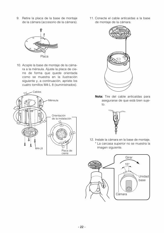
9. Retire la placa de la base de montajede la cámara (accesorio de la cámara).
10. Acople la base de montaje de la cáma-ra a la ménsula. Ajuste la placa de cie-rre de forma que quede orientadacomo se muestra en la ilustraciónsiguiente y, a continuación, apriete loscuatro tornillos M4-L 8 (suministrados).
11. Conecte el cable anticaídas a la basede montaje de la cámara.
Nota: Tire del cable anticaídas paraasegurarse de que está bien suje-to.
12. Instale la cámara en la base de montaje. * La carcasa superior no se muestra la
imagen siguiente.
- 22 -
Placa
Cables
Orientación de la instalación
Placa de cierre
M4-L8
Ménsula
15°
Girar
Cámara
Unidad base
- 23 -
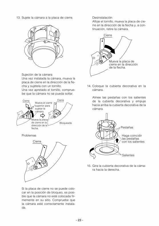
13. Sujete la cámara a la placa de cierre.
Sujeción de la cámaraUna vez instalada la cámara, mueva laplaca de cierre en la dirección de la fle-cha y sujétela con un tornillo.Una vez apretado el tornillo, comprue-be que la cámara no se pueda soltar.
Problemas
Si la placa de cierre no se puede colo-car en la posición de bloqueo, es posi-ble que la cámara no esté colocada fir-memente en su sitio. Compruebe quela cámara esté correctamente instala-da.
DesinstalaciónAfloje el tornillo, mueva la placa de cie-rre en la dirección de la flecha y, a con-tinuación, retire la cámara.
14. Coloque la cubierta decorativa en lacámara.
Alinee las pestañas con los salientesde la cubierta decorativa y empujehacia arriba la cubierta decorativa de lacámara.
15. Gira la cubierta decorativa de la cáma-ra hacia la derecha.
Lock
Cierre
Bloqueada
CierreMueva el cierre superior para sujetar la cámara.
Mueva la placa de cierre en la dirección de la flecha.
Lock
Lock
Cierre
Mueva la placa de cierre en la dirección de la flecha.
Lock
Cierre
Pestañas
Haga coincidir las pestañas con los salientes
Salientes
- 24 -
ESPECIFICACIONES
Temperatura ambiente de funcionamiento: -10˚C - +50˚CDimensiones: φ240 × 177 (Fn) mmPeso: 800 g
Los peso y dimensiones indicados son aproximados.Especificaciones sujetas a cambios sin previo aviso.
ACCESORIOS
Cable anticaídas . . . . . . . . . . . . . . . . . . . . . . . . . . . . . . . . . . . . . . . . . . 1 ud.Abrazadera de ángulo anticaídas . . . . . . . . . . . . . . . . . . . . . . . . . . . . . 1 ud.Plantilla A . . . . . . . . . . . . . . . . . . . . . . . . . . . . . . . . . . . . . . . . . . . . . . . 1 ud.Plantilla B . . . . . . . . . . . . . . . . . . . . . . . . . . . . . . . . . . . . . . . . . . . . . . . 1 ud.Tornillos (M4-L8) . . . . . . . . . . . . . . . . . . . . . . . . . . . . . . . . . . . . . . . . . . 4 uds.Cubierta de protección . . . . . . . . . . . . . . . . . . . . . . . . . . . . . . . . . . . . . 1 ud.
- 25 -
PREFAZIONE
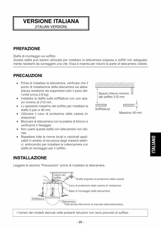
Staffa di montaggio sul soffitto: Questa staffa può essere utilizzata per installare la telecamera sospesa a soffitti non adeguata-mente resistenti da sorreggere una vite. Essa è inserita per ridurre la parte di telecamera visibile.
PRECAUZIONI
• Prima di installare la telecamera, verificare che ilpunto di installazione della telecamera sia abba-stanza resistente da sopportare tutto il peso del-l’unità (circa 2,9 kg).
• Installare la staffa sulla soffittatura con uno spa-zio minimo di 210 mm.
• Lo spessore massimo del soffitto per installare lastaffa è pari a 40 mm.
• Utilizzare il cavo di protezione dalla caduta (indotazione).
• Bloccare la telecamera con la piastra di blocco everificarne il fissaggio.
• Non usare questa staffa con telecamere non ido-nee.
• Rispettare tutte le norme locali e nazionali appli-cabili in ambito di sicurezza degli impianti elettri-ci, antincendio per installare la videocamera constaffa di montaggio per il soffitto.
Spazio interno minimo del soffitto 210 mm
SoffittaturaMassimo 40 mm
I numeri dei modelli elencati nelle presenti istruzioni non sono provvisti di suffissi.
*Fare anche riferimento al manuale della telecamera.
Interno del soffitto
Soffittatura
Base di montaggio della telecamera
Graffa angolare di protezione dalla caduta
Cavo di protezione dalla caduta (in dotazione)
Telecamera
INSTALLAZIONE
Leggere la sezione “Precauzioni” prima di installare la telecamera.
VERSIONE ITALIANA(ITALIAN VERSION)
ITAL
IANO
2. Inserire un bullone di ancoraggio (#1 nella figura) nella parte superiore del soffitto al centrodel foro effettuato nella soffittatura come descritto al passaggio 1.Inserire un altro bullone di ancoraggio (#2 nella figura) nella posizione (2) come illustratonella figura seguente.
3. Applicare un dado di ancoraggio al punto “D” , misurato utilizzando la sagoma B (in dota-zione). Misurare la lunghezza “E” utilizzando la sagoma B.
- 26 -
1. Utilizzare la sagoma A (in dotazione) per effettuare quattro fori nella soffittatura. 1-1. Eseguire i quattro fori (φ12 mm × 4) quindi tagliare e asportare l’area contrassegnata
con “C”.1-2. Effettuare il foro rotondo (φ220 mm) come illustrato nella seguente figura.
φ220 mm
Sagoma A
4-φ12 mm
φ220 mm“C”
(2) (1)
Bulloni di ancoraggio
Sagoma B
Soffittatura
“D”
“E”
169
mm
4. Applicare la graffa angola di protezio-ne dalla caduta (in dotazione) (2) inbase ai seguenti passaggi.
foro passante
Graffa angolare di protezione dalla caduta (in dotazione)
Cavo di protezione dalla caduta (in dotazione)
Due dadi distanziatori sono necessari per uti-lizzare il bullone di ancoraggio esistente.
5. Attaccare l’estremità del cavo di prote-zione dalla caduta alla graffa.5-1. Posizionare un dado di ancorag-
gio standard al bullone di anco-raggio (2).
5-2. Rimuovere il cavo di protezionedalla caduta dalla graffa angolaredi protezione dalla caduta.
5-3. Inserire il bullone di ancoraggio (2)attraverso il lato “1”.
5-4. Piegare (piegare manualmente lagraffa) lato “2” sul lato “1” (se pie-gata in modo appropriato il lato “1”e il lato “2” coincidono).
5-5. Attaccare nuovamente il cavo diprotezione dalla caduta ai foricombacianti del lato “1” e “2” dellagraffa angolare di protezione dallacaduta.
5-6. Posizionare due dadi di ancorag-gio standard al bullone di anco-raggio (2).
5-7. Stringere i tre dadi per fissare lagraffa angolare di protezione dallacaduta.
6. Collegare il cavo di protezione dallacaduta e posizionare la graffa nella sof-fittatura attraverso il foro.
7. Fissare la staffa di montaggio della tele-camera alla soffittatura ruotando insenso orario le quattro viti del pannellodella soffittatura.
8. Installare la staffa sul bullone di anco-raggio (1).
- 27 -
5-1
5-3
5-25-4
5-5 5-6
Lato “1”
Bulloni di ancoraggio
Lato “2”
Bullone di ancoraggio esistente
Dadi distanziatori
Dadi distanziatori
Graffa angolare di protezione dalla caduta
Supporto per il soffitto
Senso orario
Dado di ancoraggio
Dadi
Viti del pannello della soffittatura
9. Rimuovere la piastra dalla base di mon-taggio della telecamera (accessori tele-camera).
10. Applicare la base di montaggio dellatelecamera alla staffa. Regolare la pia-stra di blocco in modo che si troviorientata come nella seguente illustra-zione e stringere le quattro viti M4-L8(in dotazione).
11. Collegare il cavo di protezione dallacaduta alla base di montaggio dellatelecamera.
Nota: Tirare il cavo di protezione dallacaduta per accertarsi del fissag-gio.
12. Installare la telecamera sulla base dimontaggio. * La custodia superiore non è rappre-
sentata nella seguente figura.
- 28 -
Piastra
Cavi
Orientazione di installazione
Piastra di blocco
M4-L8
Staffa
15°
Girare
Telecamera
Unità base
- 29 -
13. Fissare la telecamera alla piastra di fis-saggio.
Fissaggio della telecameraDopo aver installato la telecamera, spo-stare la piastra di blocco nella direzio-ne della freccia e fissarla con una vita. Verificare che la telecamera non possaallentarsi dopo aver fissato la vite.
Problemi
Se la piastra di blocco non si spostanella posizione di blocco, probabilmen-te la telecamera non è installata corret-tamente. Verificare la corretta installa-zione della telecamera.
DisinstallazioneAllentare la vite, spostare la piastra diblocco nella direzione della freccia erimuovere la telecamera.
14. Installare il coperchio decorativo sullatelecamera.
Allineare le linguette con le sporgenzedel coperchio decorativo e premere ilcoperchio decorativo della telecamera.
15. Ruotare il coperchio decorativo dellatelecamera in senso orario.
Lock
Blocco
Bloccata
Blocco Spostare il blocco superiore per fissare la telecamera
Lock
LockBlocco
Spostare la piastra di blocco nella direzione della freccia
Spostare la piastra di blocco nella direzione della freccia
Lock
Blocco
Linguette
Far coincidere le linguette alle sporgenze
Sporgenze
- 30 -
SPECIFICHE
Temperatura operativa ambiente: -10˚C - +50˚CDimensioni: φ240 × 177 (D) mmPeso: 800 g
Le dimensioni e il peso indicati sono approssimativi.Le specifiche sono soggette a cambiamenti senza preavviso.
ACCESSORI
Cavo di protezione dalla caduta . . . . . . . . . . . . . . . . . . . . . . . . . . . . . . 1 pezzoGraffa angolare di protezione dalla caduta . . . . . . . . . . . . . . . . . . . . . . 1 pezzoSagoma A . . . . . . . . . . . . . . . . . . . . . . . . . . . . . . . . . . . . . . . . . . . . . . . 1 pezzoSagoma B . . . . . . . . . . . . . . . . . . . . . . . . . . . . . . . . . . . . . . . . . . . . . . . 1 pezzoViti (M4-L8) . . . . . . . . . . . . . . . . . . . . . . . . . . . . . . . . . . . . . . . . . . . . . . 4 pezziCoperchio protettivo . . . . . . . . . . . . . . . . . . . . . . . . . . . . . . . . . . . . . . . 1 pezzo
- 31 -
前言
天花板安装支架:
如果吊顶的强度不足以把持螺钉,可使用此支架在吊顶上安装摄像机。可将其嵌入以减少摄像机露
出的部分。
注意事项
∑ 安装摄像机前,要确保摄像机的安装位置足够
牢固以支撑整个摄像机(约2.9 kg)。
∑ 在具有210 mm最小间隔的悬挂式天花板中安装
该框架。
∑ 安装该框架的天花板最大厚度为40 mm。
∑ 请务必使用防坠钢丝索(配件)。
∑ 请务必用锁板锁住摄像机,并确保其不能脱出。
∑ 请勿将此支架用于不适合的摄像机。
∑ 使用此悬挂式天花板安装框架安装摄像机时,
请遵守当地和国家适用的有关用电、防火和安
全方面的法律法规。
天花板内部最小间隔为210 mm
悬挂式天花板最大为40 mm
这些说明中所列出的型号无后缀。
*另请参阅摄像机的说明书。
天花板内部
悬挂式天花板
摄像机安装底座
防坠角度夹
防坠钢丝索(配件)
摄像机
安装
安装摄像机前请务必阅读“注意事项”。
中 文
2. 在步骤1中描述的悬挂式天花板中所挖孔中心处将标准地脚螺栓(图中的#1)拧紧于上层混凝
土天花板。
将另一地脚螺栓(图中的#2)拧入下图所示位置(2)。
3. 在通过模板B(配件)测量的点“D”处连接一个标准地脚螺母。
通过模板B测量长度“E”。
- 32 -
1. 利用模板A(配件)在悬挂式天花板上挖出四个孔。
1-1. 挖出四个孔(f12 mm×4),然后切除标有“C”的部分。
1-2. 按以下图例将孔磨圆(f220 mm)。
φ220 mm
模板A
4-φ12 mm
“C”
(2) (1)
地脚螺栓
模板B
悬挂式天花板
“D”
“E”
169
mm
4. 根据以下步骤将防坠角度夹(配件)连
接到地脚螺栓(2)上。
穿透孔
防坠角度夹(配件)
防坠钢丝索(配件)
f220 mm
需要两个垫圈螺母与现有地脚螺栓配合使用。
5. 将防坠钢丝索的末端连接到框架上。
5-1. 将标准地脚螺母旋到地脚螺栓(2)
上。
5-2. 从防坠角度夹上拆下防坠钢丝索。
5-3. 将地脚螺栓(2)插入面“1”。
5-4. 将“2”侧向下叠压(手动弯曲角度
夹)到面“1”上(当折叠位置正确
时,面“1”和面“2”应该相互贴
合到位)。
5-5. 重新将防坠钢丝索连接到防坠角度
夹的面“1”和面“2”的配合孔中。
5-6. 将两个标准地脚螺母旋到地脚螺栓
(2)上。
5-7. 拧紧三个螺母,紧固防坠角度夹。
6. 连接防坠角度夹并通过孔将框架装入悬
挂式天花板。
7. 通过顺时针旋转四个天花板面板螺丝紧
固摄像机安装框架到悬挂式天花板。
8. 安装框架到地脚螺栓(1)上。
- 33 -
5-1
5-3
5-25-4
5-5 5-6
面“1”
地脚螺栓
面“2”
现有地脚螺栓
垫圈螺母
垫圈螺母
防坠角度夹
天花板支架
顺时针
地脚螺母
螺母
天花板面板螺丝
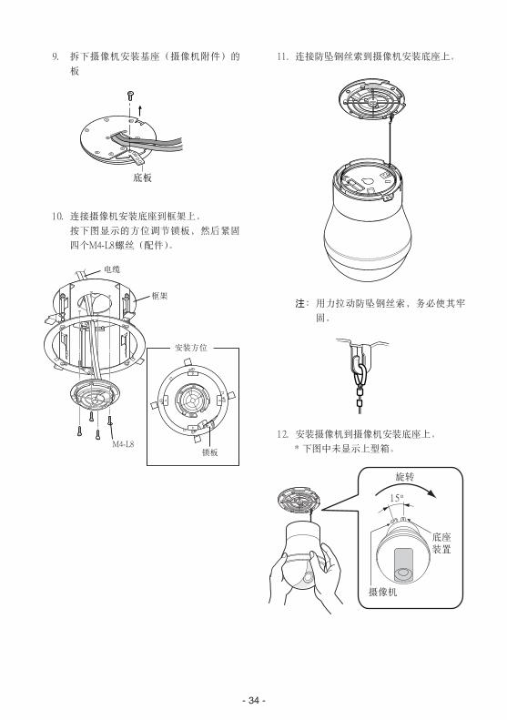
9. 拆下摄像机安装基座(摄像机附件)的
板
10. 连接摄像机安装底座到框架上。
按下图显示的方位调节锁板,然后紧固
四个M4-L8螺丝(配件)。
11. 连接防坠钢丝索到摄像机安装底座上。
注:用力拉动防坠钢丝索,务必使其牢
固。
12. 安装摄像机到摄像机安装底座上。
* 下图中未显示上型箱。
- 34 -
底板
电缆
安装方位
锁板M4-L8
框架
15∞
旋转
摄像机
底座装置

- 35 -
13. 紧固摄像机到锁板上。
紧固摄像机
安装好摄像机后,要按箭头所示方向移
动锁板并用螺丝进行紧固。
紧固螺丝后,务必使摄像机不能松动。
问题
如果锁板不能移动到锁位置,则摄像机
可能未安装牢固。务必正确安装摄像机。
未安装
松开螺丝,按箭头方向移动锁板,然后
拆下摄像机。
14. 安装装饰盖到摄像机上。
将挂钩与装饰盖突出部位对准并向上按
压摄像机装饰盖。
15. 顺时针旋转摄像机装饰盖。
Lock
锁
Lock
Lock
锁住
锁
移动上部锁,紧固摄像机。
按箭头方向移动锁板
锁
按箭头方向
移动锁板
Lock
锁
挂钩
将挂钩与突出部位
相贴合
突出部位
- 36 -
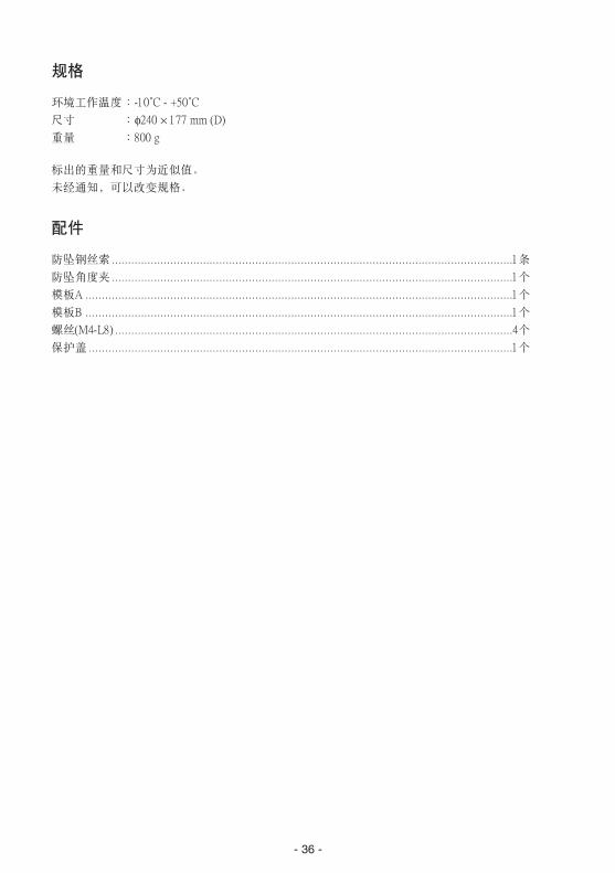
规格
环境工作温度 :-10˚C - +50˚C
尺寸 :f240 ¥ 177 mm (D)
重量 :800 g
标出的重量和尺寸为近似值。
未经通知,可以改变规格。
配件
防坠钢丝索 ...........................................................................................................................1条
防坠角度夹 ...........................................................................................................................1个
模板A ...................................................................................................................................1个
模板B ...................................................................................................................................1个
螺丝(M4-L8) ..........................................................................................................................4个
保护盖 ..................................................................................................................................1个
- 37 -
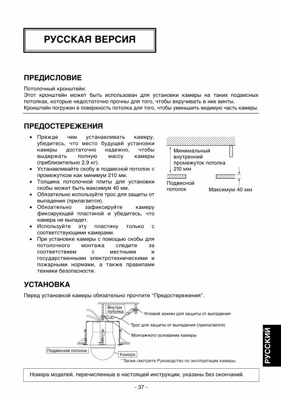
ПРЕДИСЛОВИЕПотолочный кронштейн: Этот кронштейн может быть использован для установки камеры на таких подвесныхпотолках, которые недостаточно прочны для того, чтобы вкручивать в них винты. Кронштейн погружен в поверхность потолка для того, чтобы уменьшить видимую часть камеры.
ПРЕДОСТЕРЕЖЕНИЯ• Прежде чем устанавливать камеру,
убедитесь, что место будущей установкикамеры достаточно надежно, чтобывыдержать полную массу камеры(приблизительно 2,9 кг).
• Устанавливайте скобу в подвесной потолок спромежутком как минимум 210 мм.
• Толщина потолочной плиты для установкискобы может быть максимум 40 мм.
• Обязательно используйте трос для защиты отвыпадения (прилагается).
• Обязательно зафиксируйте камеруфиксирующей пластиной и убедитесь, чтокамера не выпадет.
• Используйте эту пластину только ссоответствующими камерами.
• При установке камеры с помощью скобы дляпотолочного монтажа следите засоответствием с местными игосударственными электротехническими ипожарными нормами, а также правиламитехники безопасности.
Номера моделей, перечисленные в настоящей инструкции, указаны без окончаний.
УСТАНОВКАПеред установкой камеры обязательно прочтите “Предостережения”.
РУССКАЯ ВЕРСИЯ
РУ
СС
КИ
Й
WV-Q116E_Ru.qxd 10/10/07 10:50 Page 37
- 38 -
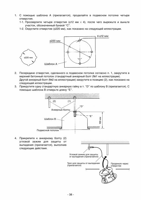
1. С помощью шаблона А (прилагается), проделайте в подвесном потолке четыреотверстия.1-1. Просверлите четыре отверстия (φ12 мм × 4), после чего вырежьте и выньте
участок, обозначенный буквой “C”.1-2. Округлите отверстие (φ220 мм), как показано на следующей иллюстрации.
4. Прикрепите к анкерному болту (2)угловой зажим для защиты отвыпадения (прилагается), выполнивследующие действия.
2. Посередине отверстия, сделанного в подвесном потолке согласно п. 1, закрутите вверхний бетонный потолок стандартный анкерный болт (№1 на иллюстрации).Другой анкерный болт (№2 на иллюстрации) закрутите в позицию (2), как показано наследующей иллюстрации.
3. Прикрутите одну стандартную анкерную гайку в т. “D” по шаблону B (прилагается). Спомощью шаблона B отмерьте длину “E”.
WV-Q116E_Ru.qxd 10/10/07 10:50 Page 38
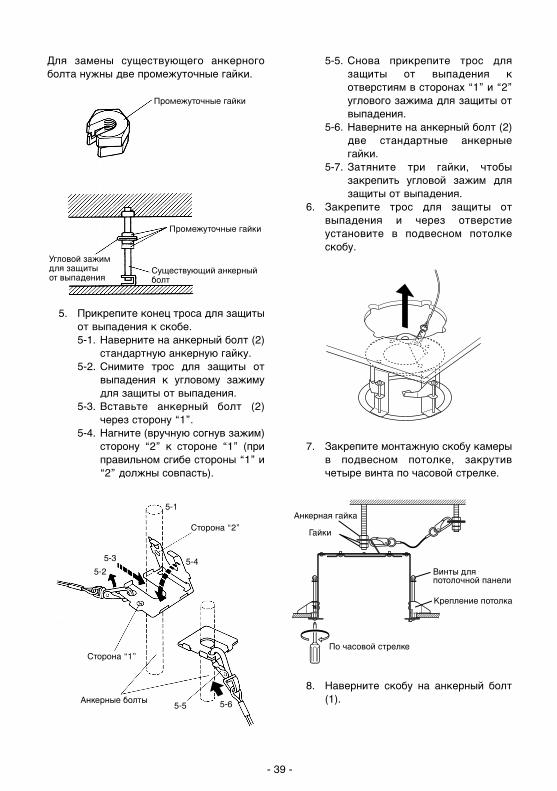
Для замены существующего анкерногоболта нужны две промежуточные гайки.
5. Прикрепите конец троса для защитыот выпадения к скобе.5-1. Наверните на анкерный болт (2)
стандартную анкерную гайку.5-2. Снимите трос для защиты от
выпадения к угловому зажимудля защиты от выпадения.
5-3. Вставьте анкерный болт (2)через сторону “1”.
5-4. Нагните (вручную согнув зажим)сторону “2” к стороне “1” (приправильном сгибе стороны “1” и“2” должны совпасть).
5-5. Снова прикрепите трос длязащиты от выпадения котверстиям в сторонах “1” и “2”углового зажима для защиты отвыпадения.
5-6. Наверните на анкерный болт (2)две стандартные анкерныегайки.
5-7. Затяните три гайки, чтобызакрепить угловой зажим длязащиты от выпадения.
6. Закрепите трос для защиты отвыпадения и через отверстиеустановите в подвесном потолкескобу.
7. Закрепите монтажную скобу камерыв подвесном потолке, закрутивчетыре винта по часовой стрелке.
8. Наверните скобу на анкерный болт(1).
- 39 -
WV-Q116E_Ru.qxd 10/10/07 10:50 Page 39

9. Снимите пластину с монтажногооснования камеры (принадлежностькамеры)
10. Прикрепите монтажное основаниекамеры к скобе. Отрегулируйте фиксирующуюпластину таким образом, чтобы ееориентация соответствовалапоказанной на рисунке, и закрутитечетыре винта M4-L 8 (прилагаются).
11. Соедините трос для защиты отвыпадения с монтажнымоснованием камеры.
Примечание: Натяните трос длязащиты от падения, чтобынадежно закрепить его.
12. Установите камеру на монтажноеоснование камеры.* Верхний кожух не показан на
следующей иллюстрации.
- 40 -
WV-Q116E_Ru.qxd 10/10/07 10:50 Page 40
- 41 -
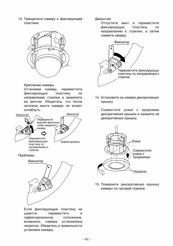
13. Прикрепите камеру к фиксирующейпластине.
Крепление камерыУстановив камеру, переместитефиксирующую пластину понаправлению стрелки и закрепитеее винтом. Убедитесь, что послезатяжки винта камера не можетослабнуть.
Проблемы
Если фиксирующую пластину неудается переместить взафиксированное положение,возможно, камера установленанепрочно. Убедитесь в правильностиустановки камеры.
ДемонтажОтпустите винт и переместитефиксирующую пластину понаправлению к стрелке, а затемснимите камеру.
14. Установите на камере декоративнуюкрышку.
Совместите усики с прорезямидекоративной крышки и нажмите надекоративную крышку.
15. Поверните декоративную крышкукамеры по часовой стрелке.
Lock
WV-Q116E_Ru.qxd 10/10/07 10:50 Page 41
- 42 -
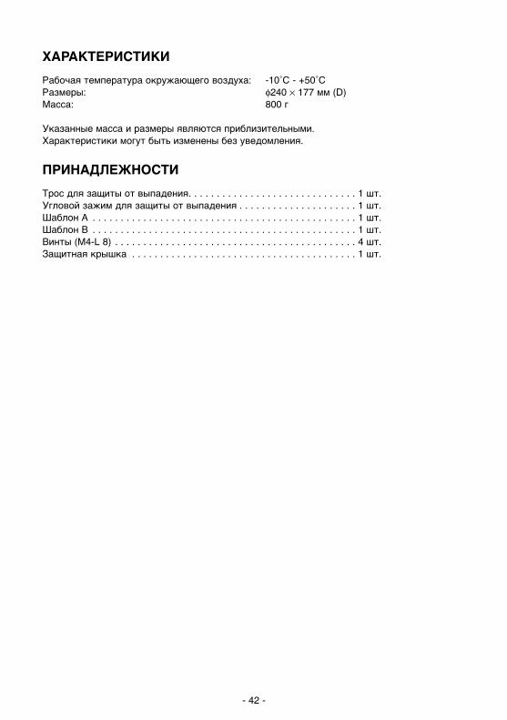
ХАРАКТЕРИСТИКИ
Рабочая температура окружающего воздуха: -10˚C - +50˚CРазмеры: φ240 × 177 мм (D)Масса: 800 г
Указанные масса и размеры являются приблизительными.Характеристики могут быть изменены без уведомления.
ПРИНАДЛЕЖНОСТИ
Трос для защиты от выпадения. . . . . . . . . . . . . . . . . . . . . . . . . . . . . . 1 шт.Угловой зажим для защиты от выпадения . . . . . . . . . . . . . . . . . . . . . 1 шт.Шаблон А . . . . . . . . . . . . . . . . . . . . . . . . . . . . . . . . . . . . . . . . . . . . . . . 1 шт.Шаблон B . . . . . . . . . . . . . . . . . . . . . . . . . . . . . . . . . . . . . . . . . . . . . . . 1 шт.Винты (M4-L 8) . . . . . . . . . . . . . . . . . . . . . . . . . . . . . . . . . . . . . . . . . . . 4 шт.Защитная крышка . . . . . . . . . . . . . . . . . . . . . . . . . . . . . . . . . . . . . . . . 1 шт.
WV-Q116E_Ru.qxd 10/10/07 10:50 Page 42

- 43 -
P43.qxd 07.10.10 7:26 PM Page 43

Printed in JapanGedruckt in JapanImprimé au JaponImpreso en Japón
Stampato in Giappone
© Panasonic Corporation 2008 AM0205-3010 3TR003450DAA