model no. : llx240ab01 - digital x-ray systems · version 1.0.2 date: 2011. 6. 20 samsung...
TRANSCRIPT

Version 1.0.2
Date: 2011. 6. 20
SAMSUNG Flat-Panel X-Ray Detector
MODEL NO. : LLX240AB01
User Manual
Samsung Mobile Display Co. , Ltd.
This manual is provided for the installation and operation of LTX240AA01-A.
Please read this manual before the detector install and use.
© 2011 Samsung Mobile Display Co., Ltd. All rights reserved.
SAMSUNG
MOBILE DISPLAY

CAUTION : United States federal law restricts this device to use
by or in the order of a physician.
Samsung Mobile Display Co., Ltd.
Indication for use
LLX240AB01 Digital Flat Panel X-ray Detector is indicated for digital imaging
solution designed for general radiographic system for human anatomy. It is
intended to replace film or screen based radiographic systems in all general
purpose diagnostic procedures. Not to be used for mammography.

Attention
For improvement of product performance, supplementation, or follow-up of information; the contents
of this manual are subject to change without separate prior notice.
Please note that our company has neither responsibility for any accidents nor obligation to do free
repair service for any damage of the equipment due to user's mistake, which resulted from failure to
follow the contents in this manual. Make sure to be familiar with the safety precautions and usage
procedures. Also note that the product may slightly differ from the contents of this manual
depending on specification.
The following marks are used for the effective use of the product in this manual.
Attention, consult accompanying documents.
This is used to emphasize essential information. Be sure to read this
information to avoid incorrect operation.
This indicates hazardous situation which, if not heeded, may result in
minor or moderate injury to you or others, or may result in machine
damage.
This indicates a potentially hazardous situation which, if not heeded, could
result in death or serious injury to you or others.
Federal Law restricts this device to sale by or the order of a radiologist or
any other practitioners licensed by the law of the state in which that
person practices to use or order the use of the device.

Contents Introduction ........................................................................................... 1
Overview ................................................................................................ 1 Product features ................................................................................... 1 Product components ............................................................................ 2 Components Description ..................................................................... 3 Warning .................................................................................................. 4 Caution ................................................................................................... 6 Marking and labeling symbols ............................................................ 8
Technical Features ............................................................................. 10
Mechanical Features .......................................................................... 10 Electrical Features .............................................................................. 10 Environmental requirement ............................................................... 14 PC Requirements ................................................................................ 14
Installation .......................................................................................... 15
Caution ................................................................................................. 15 Connection .......................................................................................... 15 Checking Connection ......................................................................... 19 Power on Sequence ............................................................................ 20 Description of Detector indicator ...................................................... 20
Calibration ........................................................................................... 21
General Principle ................................................................................ 21 Calibration ........................................................................................... 23
Image Acquisition Test ....................................................................... 28
Program setup ..................................................................................... 28 Get Image ............................................................................................. 29 View Images ........................................................................................ 30
Operation ............................................................................................. 35
Recommendation ................................................................................ 35 Switching power on / off .................................................................... 35 Initialization ......................................................................................... 36 Arrangement ........................................................................................ 36 Image acquisition................................................................................ 37
Safety information ............................................................................... 38
Safety standard ................................................................................... 38 Electromagnetic Compatibility Information ..................................... 39
Maintenance ........................................................................................ 44
Maintenance ........................................................................................ 44 Inspection ............................................................................................ 44 Warranty Seal ...................................................................................... 46
Appendix .............................................................................................. 47

1
Introduction
Overview
LLX240AB01 is an X-ray image acquisition device that is based
on flat-panel. This device should be integrated with an operating
PC and an X-ray generator. It can do to utilize as digitalizing X-
ray images and transfer for radiography diagnostic.
Product features
Figure 1: LLX240AB01
The surface of housing is made of the metal and X-ray window
area is covered with carbon. Inner circuit of detector uses lead to
protect it from X-ray and has a structure protecting the inner
circuit from X-ray dose under the limits
Based on a-Si TFT active matrix
Wide image
14-bit digital output
Easy integration

2
Product components
Detector (LLX240AB01)
Power Supply (SPS01)
Cables
- Detector and power supply link cable (10m)
- X-ray enable cable (10m)
- Ethernet cable for communication (10m)
- AC power supply cord
Installation CD which contains software for operation and
manual
- Manual (User, Service)
Printed final test report

3
Components Description
Detector
Figure 2: Detector
Number Description
① Grounding bolt (There is no extra cable)
② Main board power connector (DC)
③ AC power connector (AC 100V) (Caution high voltage)
④ X-ray enable connector
⑤ Ethernet port for transmitting the image/command between detector and PC
⑥ Four LEDs to display the status
Power Supply
Figure 3: Power supply
Number Description
① Power connector for detector operating
② Light up at 5V operating in power supply
③ 110V / 220V select switch – 110V or 220V select
(Within 100~120V, 200~240V range)
④
Input Power on / Power off by main power switch
⑤
Connect with AC power supply cord
If the noise is detected,
○1 port of
figure 2 should be connected with ground.
⑤

4
Warning
Environment of Use and Storage
Follow the specified process of operational instructions written in
this manual for the safety of the users and patients.
Does not use or store the instrument near any flammable
chemicals such as thinner, benzene, etc. Also, this instrument is
not a category AP or APG equipment. If chemicals are spilled or
evaporate, it may result in fire or electric shock through contact
with electric parts inside the instruments. Also, some
disinfectants are flammable. Be sure to take care when using
them.
Connection
Do not connect the instrument with anything other than specified.
Otherwise, it may result in fire or electric shock.
Power Supply
Power Supply must separate users and patients before
connecting cable.
Be sure to turn OFF the power of each instrument before
connecting or disconnecting the cables. Also, do not handle them
with wet hands. Otherwise, you may get an electric shock that
may result in death or serious injury.
Be sure to hold the plug or connector to disconnect the cable.
If you pull the cable, the core wire may be damaged, resulting in
fire or electric shock.
Do not cut or process the cables. Also, do not place anything
heavy, including the instrument on it, step on it, pull it, bend it, or
Make sure to observe the following right

5
bundle it. Otherwise, the cable may be damaged, which may
result in fire or electric shock.
Do not turn ON the system power when condensation is formed
on the instrument. Otherwise, it may result in fire or electric shock.
Handling
Always be sure to keep checking the condition of the system and
the patient to ensure they are normal during the use of the
instrument. If any problem is found, take appropriate measures,
such as stopping the operation of the instrument, as required.
Never disassemble or modify the product as it may result in fire
or electric shock. Also, since the instrument incorporates parts
that may cause electric shocks and other hazardous parts,
touching them may cause death or serious injury.
Do not hit or drop the instrument. The instrument may be
damaged if it receives a strong jolt, which may result in fire or
electric shock if the instrument is used without it being repaired.
When Problem Occurs
Should any of the following occur, immediately turn OFF the
power of each instruments, unplug the power supply cord from
the AC outlet, and contact VATECH representative or distributor.
When there is smoke, odd smell or abnormal sound.
When liquid has been spilled into the instrument or a metal
object has entered through an opening.
When the instrument has been dropped and it is damaged.

6
Maintenance and Inspection
For safety reasons, be sure to turn OFF the power of each
instrument when the inspections indicated in this manual are
going to be performed. Otherwise, it may result in electric shock.
When the instrument is going to be cleaned, be sure to turn OFF
the power of each instrument, and unplug the power supply cord
from the AC outlet. Never use benzene, thinner or any other
flammable cleaning agents. Otherwise, fire or electric shock may
result.
The instrument must be repaired by a qualified engineer only. If it
is not repaired properly, it may cause fire, electric shock, or
accident.
Caution
Environment of Use and Storage
Do not install the instrument in a location with the conditions
listed below. Otherwise, it may result in failure or malfunction, fall
or cause fire or injury.
Close to facilities where water is used.
Where it will be exposed to direct sunlight.
Close to air-conditioner or ventilation equipment.
Close to heat source such as a heater.
Prone to vibration.
Insecure place.
Dusty environment.
Saline or sulfurous environment.
High temperature or humidity.
Freezing or condensation.
Make sure to observe the following right.

7
Do not place the storage case in a location with the conditions
listed below.
Where the cable of the sensor unit will be strongly pulled
when the sensor unit is put into the case, otherwise, the cable
may be damaged, resulting in fire or electric shock.
Where someone might get their foot caught in the cable of the
sensor unit is put in the case. Otherwise they could trip over,
resulting in injury
Power Supply
Because the instrument‟s cable is long, take care so cables do
not get tangled during use. Also, be careful not to get your feet
caught in the cable.
Handling
Do not spill liquid or chemicals onto the instrument or, in cases
where the patient is injured, allow it to become wet with blood or
other body fluids, as doing so may result in fire or electric shock.
In such situation, protect the instrument with disposable covering
as necessary.
Wipe the CFRP plate of the sensor unit with ethanol or
glutaraldehyde solution to disinfect it each time a different patient
uses the instrument, in order to prevent infection.
Turn off the power of each instrument for safety when they are
not going to be used.
Maintenance and Inspection
For safety reasons, be sure to inspect the instrument before
using it. In addition, carry out a regular inspection at least once a
year.

8
Marking and labeling symbols
Symbols
Symbols Meaning
Alternate current
Attention
Protective earth (Ground)
Power off (disconnect from the main switch)
Power on (connect to the main switch)
Direct current
Both direct and alternating current
EC Representative
CE symbol grants the product compliance to
the European Directive for Medical Devices
93/42/EEC as a class Ⅱa device. Authorized by
Notified Body SGS (code no.:0120) of British

9
Labels
- Detector
- Power Supply
LLX240AB01

10
Technical Features
Mechanical Features
Dimension and Weight
Component (W x L x H) Weight
Detector 500 x 497 x 45mm 13.4kg
Power Supply 288 x 245 x 67 mm 4 kg
Fixation
Position of fixation – Refer to the drawing (Appendix.1)
Electrical Features
Power requirements
AC100-120V/200-240V~50/60Hz, 3.15A
The main power fuse is a 3.15A, 250V~ Type T fuse
(For North America - For 120 Volt applications, use only UL
Listed detachable power cord with NEMA configuration 5-15P
type (parallel blades) plug cap. For 240 Volt applications use only
UL Listed Detachable power supply cord with NEMA
configuration 6-15P type (tandem blades) plug cap)
Power supply Connector
Supply power Input range Current
consumption
DC5V -0.2V, +0.3V 800mA
DC5V -0.2V, +0.3V 500mA
DC24V -1.5V, +0.5V 100mA
DC-8V ±0.5V 500mA
AC100V(400Hz) ±10V(±20Hz) 60mA
Using screw – M4, depth under 9mm

11
X-ray enable cable
LEMO(EGG.1B.308) (PIN) PIN Description
1 SPARE
2 SPARE
3 READY DONE
4 READY DONE COM
5 READY IN
6 CANCEL IN
7 12V ~ 24VDC
Figure 4:X-ray enable cable
Ethernet Connector
Data transmission using port ⑤ in figure 2, 10/100Mbps Ethernet
(TCP/IP)

12
Functional Specific Features
Block Diagram
Figure 5: Block Diagram
General Rating
Parameter Unit Specification
Model - LLX240AB01
Sensor type - a-Si TFT
X-ray convertor - Gd2O2S:Tb
Application - General Radiography
Dimension(W x L x T) mm 500x497x45
Weight kg 13.4
Pixel size μm 143
Active area mm 439.3x439.3
Active array pixles 3072x3072
Effective area
mm 429x429
Effective array
pixels 3000x3000

13
Specification
Parameter Unit Specification
Model - LLX240AB01
A/D bits 14
Frame rate
fps 240 fph
Dynamic Range
dB > 73
ADC resolution bits 14
Spatial Resolution*1
lp/mm
3.5
Sensitivity*2 LSB/μGy*
3 > 80
Energy range kVp 40 ~ 150
*1: line pair resolution at over 10% MTF
*2: under RQA5 condition
*3: 1mR=8.69μGy
Software Features
Use the 100Mbps Ethernet to enhance compatibility of interface
and to transmit the control signal and data
< Functions supported by software >
- LED Check : built-in function checking for the indicator LEDs
- Version check function (Scintillator, panel, board, firmware
versions can be checked)
- EL status check and correction
- Readout and gate IC check
- test pattern generation

14
Environmental requirement
The detector must be operated within the specified temperature
and humidity in order to maintain its optimum performance.
PC Requirements
- Processor: At least Intel Pentium IV HT with 2.8GHz, Intel Core
Duo / Core 2 or comparable AMD Dual Core processor
- At least 2 GB RAM
- Upper than Intel(R) PRO/100 VE Network card
- OS: Windows XP professional
Parameter Specification
Operation condition
Temperature : +10 ~ +40 ℃
Humidity : 20 ~ 75%(no condensation)
Pressure : 70 ~ 106 kPa
Storage condition
Temperature : -25 ~ +55 ℃
Humidity : 10 ~ 95 %(no condensation)
Pressure : 70 ~ 106 kPa

15
Installation
The Detector is composed of sensitive electronic parts and
components. Therefore it must be grounded by ESD protection
equipment before it is installed in operational place. It is
recommended to use the product in a clean place and to exercise
caution to ensure that it is not affected by dust or liquids. It is
recommended to Use a dry and soft cloth to clean the detector
housing.
Caution
Cable Bending Radius is limited by six times of cable‟s diameter.
If you bend a cable over six times of cable‟s diameter, it is able to
make damage to cable.
Connection
Figure 6: Detector
Figure 7: Power supply
Imaging processing unit must be installed in a way that enables the user to achieve optimal use

16
Power & Ethernet Connection
Connect the detector and power supply link cable from the
power supply(⑤) to the Detector (③, ④)
Connect the ethernet cable from the detector (①) to the
console PC.
Transmission speed may be different with PC performance so
it is recommended to use a 100 Mbps switching hub.
※ Frame ground needed.
X-ray Enable Connection
Connect the X-ray enable cable from the detector (②) to the
X-ray generator.
Connection description
Signal Label Input / Output
READY IN +12V ~ +24V Input
READY IN Input
READY DONE READY DONE Output
READY DONE COM Output
Figure 8: Generator & detector connection

17
Operating description
Figure 9: Timing chart
t1 : Offset stabilization time (0.7Sec ~ 0.9sec)
t2 : Window time (Editing parameter: Exposure Time)
Operating step
1st step: Generator sends “READY IN” signal to the detector
2nd step: Detector waits for offset stabilization during “t1” second
3rd step: Detector sends “READY DONE” signal to the generator
4th step: Generator makes X-ray exposure in “t2” second (the
maximum exposure time is “t2”)

18
Edit parameter in “Functions”
Figure 10: Function edit

19
IP set up
<Console PC>
[My Network Places] → [Properties] → [Local Area Connection]
→ [Properties] → [Internet Protocol (TCP/IP)]
→ [Use the following IP address]
IP address : 192 . 168 . 1 . 20 (Console PC)
※ Detector IP address is 192. 168. 1. 80 (default)
Figure 11: IP set up
※ It is possible to change IP address, but it shouldn‟t be the
same as the detector IP address.
Checking Connection
Check LED on the detector & power supply
Ping test : [Start] →[Run] →ping –t 192.168.1.80
20
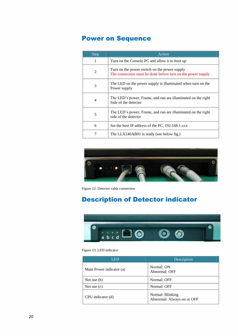
Power on Sequence
Step Action
1 Turn on the Console PC and allow it to boot up
2 Turn on the power switch on the power supply
The connection must be done before turn on the power supply
3 The LED on the power supply is illuminated when turn on the
Power supply
4 The LED’s power, Frame, and run are illuminated on the right
Side of the detector
5 The LED’s power, Frame, and run are illuminated on the right
side of the detector
6 Set the host IP address of the PC, 192.168.1.xxx
7 The LLX240AB01 is ready (see below fig.)
Figure 12: Detector cable connection
Description of Detector indicator
Figure 13: LED indicator
LED Description
Main Power indicator (a) Normal: ON
Abnormal: OFF
Not use (b) Normal: OFF
Not use (c) Normal: OFF
CPU indicator (d) Normal: Blinking
Abnormal: Always on or OFF

21
Calibration
General Principle
Notation
Calibration can be done by image acquisition software. The gain-
offset correction (under calibration) will be done with one dark, at
least one bright and object frame.
Parameter Description
Offset Dark image, acquired image without X-ray exposure
Bright Acquired image with X-ray exposure
Object Bright image with object, will be calibrated
Gain Gain of imaging system, offset subtracted image
Offset correction Offset subtract
Gain correction Compensate gain variance of pixel
X-ray detector
should be used in a stable state within operating temperature range. Acquire X-ray images after powered on and warmed up for 30 minutes to obtain high quality images.

22
Bright Calibration Point
To adjust the gain correction the bright frame and dark frame
should be acquired. Only one dark frame is needed. Acquire
more than three bright frames at three different levels of median
values. The recommended tube energy level is 70kVp with
variable tube current and exposure time. Acquire at least 3
frames at same condition is recommended. The median values of
bright frames are below.
The Purpose of Bright Calibration
The center of the non calibrated image is brighter than the edge
due to hill effect of x-ray exposure. Generally, the intensity of x-
ray flux at center region of exposed area is higher than
surroundings due to the x-ray expose like cone shape. A
calibration process is used to compensate for this effect.
Generally, called it „Flat Field Correction‟ (Bright calibration).
Figure 14: Comparison of flat field correction processing
Point 1 2 3 4 5 6 7 8
Median Value
[LSB]
850 ~
1150
1850 ~
2150
2850 ~
3150
3850 ~
4150
5850 ~
6150
7850 ~
8150
9850 ~
10150
11850 ~
12150
Table 1 : Median value
The calibration range of bright is can be select by which exposure level is maximum level that user want to use. If the maximum level of user want to use is ‘6200’ in this case the level is contained in Bright point of ‘4’(refer ‘Table 5 : Median value’). The meaning is you don’t have to make bright point for ‘5’ and ‘6’(In this case, it will be does not working if you get image on higher level than maximum bright point.)

23
Calibration
Description of calibration step by step.
1st Step
Click the “Calibration” tab and then click on the “Get Dark” button.
The acquired dark frame “dark.raw” will be generated in the “\cal\”
folder.
Figure 15: Get dark

24
2nd Step
Click the “Get Bright” button at six different
levels of X-ray conditions. The X-ray condition should be set or
tested beforehand, same as the level of „1.2‟. Click the “Get
Bright” button at least 3 times for each set of conditions, and then
the offset subtracted bright (gain) is generated with a filename of
“x „median value of gain‟ A”.(Refer to NOTE)
Figure 16: Get bright.
Click the button [Get Bright]. It will produce a frame with the name %CAL% xNNNNNA.raw, where NNNNN is the median pixel’s value within current image borders after offset calibration (cut frame edges are never used during calibration). A suffix ‘A’, ‘B’,’C’ etc. avoids an unintentional coincidence of file names.

25
3rd step
After 2nd step, the “Generate” button will be activated. Click the
button “Generate”, and then calibration point will be generated
which of file name is “A „# of point‟_ „median value of generated
point‟” like file of bright frame. The acquired bright frames within
tolerance value which is variance of median level of acquired
bright frames will be averaged and generated to a calibration
point. The tolerance value can be edited.
Figure 17: Generate
After making
calibration point the
“Generate” button will
be disabling.

26
4th step
After 3rd step, change to the Bad Pixels Removal tab, Click the
button “Generate Auto BPM”, and then Defect Map will be
generated of which the file name is “BPM.raw “in the “\cal\” folder.
Figure 18: Bad pixels removal
27
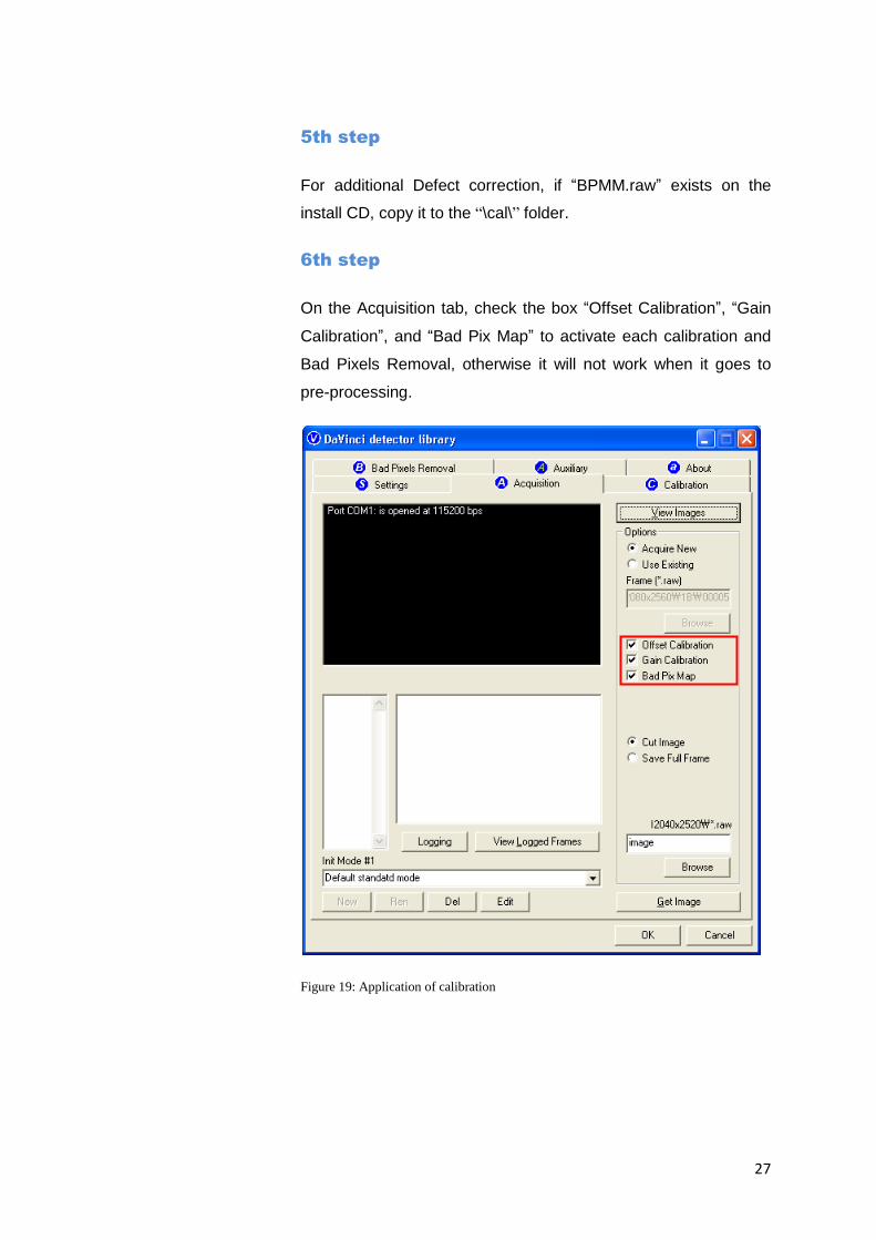
5th step
For additional Defect correction, if “BPMM.raw” exists on the
install CD, copy it to the “\cal\” folder.
6th step
On the Acquisition tab, check the box “Offset Calibration”, “Gain
Calibration”, and “Bad Pix Map” to activate each calibration and
Bad Pixels Removal, otherwise it will not work when it goes to
pre-processing.
Figure 19: Application of calibration

28
Image Acquisition Test
Program setup
To acquire images, run Vadav.Exe program.
Please set the following figures
Detector‟s IP : 192.168.1.80
Detector„s number of ADC : 6
Detector‟s size of image : 3072 X 3072
Figure 20: Setup

29
Get Image
On the Acquisition tab, click the “Get Image” button to get an
image. After clicking the button, you will see a pop-up window,
which displays in the window the time and process of acquiring
the image.
Figure 21: Get image

30
View Images
Frame and image files have the extension “raw” and contain pixel
data in signed 16-bits little-endian format. These files can be
viewed in Photoshop or another image editor.
Figure 22: View images

31
Common controls and displayed statistics
Figure 23: Description of viewer 1
Pixel_Min – minimum pixel value in frame- or image- data
Pixel_Max – maximum pixel value
Pixel_Black – if a pixel ≤ Pixel_Black then it is displayed as
black (RGB 0, 0, 0)
Pixel_White – if a pixel ≥ Pixel_Black then it is displayed as
black (RGB 255, 255, 255)
Histogram truncation in bright (in 0.1%)
Histogram truncation in dark (in 0.1%)
Select display window by histogram
truncation or by absolute pixel’s values

32
Histogram’s presentation
Relative Histogram Scale [H]=1000 means that that the distance
depicted as “H” on the drawing matches 1% of total number of
pixels. Respectively [H]=100 means that “H” matches 0.1% of
pixels and [H]=500 means that “H” matches 0.5% of pixels.
Figure 24: Description of histogram
Relative histogram scale
Histogram Maximum Value
Histogram Minimum Value

33
Marker type “S”
Displays local surround of selected location
Figure 25: Description of marker type "S"
Marker type “R”
Display profile chart of a row.
Figure 26: Description of marker type "R"
34
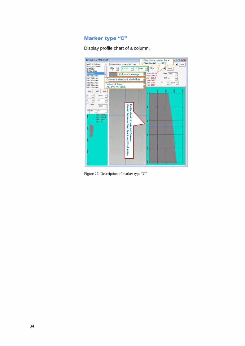
Marker type “C”
Display profile chart of a column.
Figure 27: Description of marker type "C"

35
Operation
Recommendation
X-ray detector should be used in a stable state within operating
temperature range.
Acquire X-ray images after powered on and warmed up for 30
minutes to obtain high quality images.
Switching power on / off
After turn on the main power switch of the power supply check
the four LED indicators. MCU status is OK If the yellow light of
the LED is blinking.
1) Verify the AC power and set the voltage Select software
2) Power switch ON
3) If external power supply is OK, then the green light of the LED
will be ON
4) 3 seconds later, the yellow light of the LED will blink showing
that the MCU is working properly.
If not, power OFF in advance and power ON again after 10
seconds
5) If it is linked with the Console PC in order, LED of Ethernet
port will light up and twinkle

36
Initialization
Initial data is stored in MCU (Linux) inside of detector and driven
by stored parameter data.
The stored initial parameters can be changed in software.
Arrangement
Connectors of detector is left side when acquire image like below.

37
Figure 28: Arrangement
Image acquisition
Refer to the software manual

38
Safety information
Safety standard
This equipment has been tested and found to comply with the
limits for medical devices in IEC 60601-1-2:1994. These limits
are designed to provide reasonable protection against harmful
interference in a typical medical installation.
This equipment generate, uses and can radiate radio frequency
energy and, if not installed and used in accordance with the
instructions, may cause harmful interference to other devices in
the vicinity. However, there is no guarantee that interference will
not occur in a particular installation. If this equipment does cause
harmful interference to other devices, which can be determined
by turning the equipment off and on, the user is encouraged to try
to correct the interference by one or more of the following
measures:
Reorient or relocate the receiving device.
Increase the separation between the equipment.
Connect the equipment into an outlet on a circuit different
from that to which the other devices are connected.
Consult the manufacturer or field service technician for help
(e.g., IEC 60950-1 for IT equipment and IEC 60601-1 series for
medical electrical equipment).
In addition, all such combination system shall comply with the
standard IEC 60601-1 and/or IEC 60601-1 harmonized national
standard or the combination. If in doubt, contact qualified
technician or your local representative.
Do not touch signal input, signal output or other connectors, and the patient simultaneously. External equipment intended for connection to signal input, signal output or other connectors, shall comply with relevant IEC Standard.

39
Type of protection against electric shock: Class I equipment
Degree of protection against electric shock: Not classified -
no applied parts
Classification according to the degree of protection against
ingress of water as detailed in the current edition of IEC 529:
IPX0, ordinary equipment
This equipment is not suitable for use in the presence of
flammable anesthetics or oxygen.
Mode of operation: continuous operation
Identification of specified external power supplies or battery
chargers necessary to ensure compliance with the
requirements of IEC601-1
Power supply(SPS01) has tested by IEC 60601-1 standard.
Electromagnetic Compatibility Information
Guidance and manufacturer’s declaration - electromagnetic emissions
The EUT is intended for use in the electromagnetic environment specified below. The customer or the user of the EUT should assure that it is used in such an environment.
Immunity Test Compliance Electromagnetic Environment - Guidance
RF Emissions CISPR 11
Group 1 The EUT uses RF energy only for its internal function. Therefore, its RF emissions are very low and are not likely to cause any interference in nearby electronic equipment
RF Emissions CISPR 11
Class A The EUT is suitable for use in ail establishments, including domestic establishments and those directly connected to the public low-voltage power supply network that supplies buildings used for domestic purposes
Harmonic emissions IEC 61000-3-2
Complies The EUT is suitable for use in ail establishments, including domestic establishments and those directly connected to the public low-voltage power supply network that supplies buildings used for domestic purposes
Voltage fluctuations/ Flicker emissions IEC 61000-3-3
Complies The EUT is suitable for use in ail establishments, including domestic establishments and those directly connected to the public low-voltage power supply network that supplies buildings used for domestic purposes

40
Guidance and manufacturer’s declaration - electromagnetic immunity
The EUT is intended for use in the electromagnetic environment specified below.
The customer or the user of the EUT should assure that it is used in such an environment.
The EUT is intended for use in the electromagnetic environment specified below. The customer or the user of the EUT should assure that it is used in such an environment.
Immunity test IEC 60601-1-2 Test level
Compliance level Electromagnetic environment -guidance
Electrostatic discharge (ESD) IEC 61000-4-2
±6kV Contact ±8kV air
±6kV Contact ±8kV air
Floors should be wood, concrete or ceramic tile. If floors are covered with synthetic material, the relative humidity should be at least 30%.
Electrical fast transient/burst IEC 61000-4-4
±2kV for power supply lines
± 1kV for input/output
lines
±2kV for power supply lines
± 1kV for input/output lines
Mains power quality should be that of a typical commercial or hospital environment.
Surge IEC 61000-4-5
±1kV differential mode
±2kV common mode
±1kV differential mode
±2kV common mode
Mains power quality should be that of a typical commercial or hospital environment.
Voltage dips, short
interruptions and voltage
variations on power supply
input lines IEC 61000-4-11
<5% Uт (>95% dip in Uт) for 0.5cycle 40% Uт (60% dip in Uт ) for 5 cycle 70% Uт (30% dip in Uт) for 25 cycle <5% Uт (<95% dip in Uт ) for 5 s
<5% Uт (>95% dip in Uт) for 0.5cycle 40% Uт (60% dip in Uт ) for 5 cycle 70% Uт (30% dip in Uт) for 25 cycle <5% Uт (<95% dip in Uт ) for 5 s
Mains power quality should be that of a typical commercial or hospital environment. If the user of the EUT image intensifier requires continued operation during power mains interruptions, it is recommended that the EUT image intensifier be powered from an uninterruptible power supply or a battery.
Power frequency (50/60Hz)
magnetic field IEC 61000-4-8
3 A/m 3 A/m Power frequency magnetic fields should be at levels characteristic of a typical location in a typical commercial or hospital environment.
NOTE Uт is the a.c. mains voltage prior to application of the test level.

41
Guidance and manufacturer’s declaration - electromagnetic immunity
The EUT is intended for use in the electromagnetic environment specified below.
The customer or the user of the EUT should assure that it is used in such an environment.
Immunity test IEC 60601-1-2 test level
Compliance level
Electromagnetic environment - guidance
Conducted RF IEC 61000-4-6 Radiated RF IEC 61000-4-3
3 Vrms 150 kHz to 80MHz 3 V/m 80 MHz to 2.5GHz
V
1=3Vrms
E1=3V/m
Portable and mobile RF communications equipment should be used no closer to any part of the EUT, including cables, than the recommended separation distance calculated from the equation applicable to the frequency of the transmitter. Recommended separation distance :
where P is the maximum output power rating of the transmitter in watts (W) according to the transmitter manufacturer and d is the recommended separation distance in meters (m). Field strengths from fixed RF transmitters, as deter-
mined by an electromagnetic site survey, a
should be less than the compliance level in each
frequency range. b
Interference may occur in the vicinity of equipment marked with the following symbol :
NOTE 1) At 80MHz and 800MHz, the higher frequency range applies. NOTE 2) These guidelines may not apply in all situations. Electromagnetic propagation is affected by

42
absorption and reflection from structures, objects and people.
a
Field strengths from fixed transmitters, such as base stations for radio (cellular/cordless) telephones and land mobile radios, amateur radio, AM and FM radio broadcast and TV broadcast cannot be predicted theoretically with accuracy. To assess the electromagnetic environment due to fixed RF transmitters, an electromagnetic site survey should be considered. If the measured field strength in the location in which the EUT is used exceeds the applicable RF compliance level above, the EUT should be observed to verify normal operation. If abnormal performance is observed, additional measures may be necessary, such as re-orienting or relocating the EUT. b
Over the frequency range 150kHz to 80MHz, field strengths should be less than [V1] V/m.
Recommended separation distances between portable and mobile RF communications equipment and the EUT
There is intended for use in an electromagnetic environment in which radiated RF disturbances are controlled. The customer or the user of the EUT can help Prevent electromagnetic interference by maintaining a minimum distance between portable and mobile RF communications equipment (transmitters) and the EUT as recommended below, according to the maximum output power of the communications equipment.
Separation distance according to frequency of transmitter [m] IEC 60601-1-2
Frequency of Transmitter
Equation
Rated maximum output power of
transmitter [W]
150kHz to 80MHz
V1=3Vrms
Separation Distance
(meters)
80MHz to 800MHz
E1=3V/m
Separation Distance
(meters)
800MHz to 2.5GHz
E1=3V/m
Separation Distance
(meters)
0.01 0.116 0.1166 0.2333
0.1 0.368 0.3687 0.7378
1 1.166 1.1660 2.3333
10 3.687 3.6872 7.3785
100 11.660 11.6600 23.333
For transmitters rated at a maximum output power not listed above, the recommended separation distance d in meters (m) can be estimated using the equation applicable to the frequency of the transmitter, where p is the maximum output power rating of the transmitter in watts (W) according to the transmitter manufacturer. NOTE 1) At 80MHz and 800MHz, the separation distance for the higher frequency range applies. NOTE 2) These guidelines may not apply in all situations. Electromagnetic propagation is affected by absorption and reflection from structures, objects and people. a Field strengths from fixed transmitters, such as base stations for radio (cellular/cordless) telephones and land mobile radios, amateur radio, AM and FM radio broadcast and TV broadcast cannot be predicted theoretically with accuracy. To assess the electromagnetic environment due to fixed RF transmitters, an electromagnetic site survey should be considered. If the measured field strength in the location in which the EUT is used exceeds the applicable RF compliance level above, the EUT should be observed to

43
verify normal operation. If abnormal performance is observed, additional measures may be necessary, such as re-orienting or relocating the EUT. b Over the frequency range 150kHz to 80MHz, field strengths should be less than [V1] V/m.
Immunity and Compliance Level
Immunity test IEC 60601-1-2 Test Level
Actual Immunity Level Compliance Level
Conducted RF IEC 61000-4-6
3Vrms 150kHz to 80MHz
3Vrms 3Vrms
Radiated RF IEC 61000-4-3
3Vrms 80MHz to 2.5GHz
3V/m 3V/m
Guidance and manufacturer’s declaration - electromagnetic immunity
The EUT is intended for use in the electromagnetic environment specified below. The customer or the user of the EUT should assure that it is used in such an electromagnetic environment.
Immunity test IEC 60601-1-2 Test level
Compliance level
Electromagnetic environment - guidance
Conducted RF IEC
61000-4-6
Radiated RF IEC 61000-4-
3
3 Vrms 150kHz to
80MHz
3V/m 80MHz
to 2.5GHz
3 Vrms 150 kHz to
80MHz
3V/m 80MHz
to 2.5GHz
The EUT must be used only in a shielded location with a minimum RH shielding effectiveness nad, for each cable that enters the shielded location with a minimum RF shielding effectiveness and, for each cable that enters the shielded location. Field strengths outside the shielded location from fixed RF transmitters, as determined by an electromagnetic site survey, should be less than
3V/m.a
Interference may occur in the vicinity of equipment marked with the following symbol:
NOTE 1) These guidelines may not apply in all situations. Electromagnetic propagation is affected by absorption and reflection from structures, objects and people. NOTE 2) It is essential that the actual shielding effectiveness and filter attenuation of the shielded location be verified to assure that they meet the minimum specification. a
Field strengths from fixed transmitters, such as base stations for radio (cellular/cordless) telephones and land mobile radios, amateur radio, AM and FM radio broadcast and TV broadcast cannot be predicted theoretically with accuracy. To assess the electromagnetic environment due to fixed RF transmitters, an electromagnetic site survey should be considered. If the measured field strength outside the shielded location in which the EUT is used exceeds 3V/m, the EUT should be observed to verify normal operation. If abnormal performance is observed, additional measures may be necessary, such as relocating the EUT or using a shielded location with a higher RF shielding effectiveness and filter attenuation.

44
Maintenance
Maintenance
Maintenance of the detector does not directly. Maintenance
should be gone by service provider
If the Detector Panel is defective, the detector will be
returned as is to the manufacturer for repair
Clean the equipment with a dry soft cloth, or a soft cloth
lightly moistened with mild detergent solution. Do not use any
type of solvent, such as benzene
This equipment and accessories are to be disposed of safely
after the life span of them and national regulation must be
observed.
For safety reasons, be sure to inspect the instrument before
using it. In addition, carry out a regular inspection at least
once a year.
Arrange the detector and power supply link cable to prevent
the damage of the cable‟s rubber tube. For example, do not
press the cable under the legs of the table or the people.
Inspection
In order to ensure that the instrument is used safely and normally,
please be sure to inspect the instrument before use. If any
problem is found during the inspection, please take measures
indicated in this chapter. If the problem still cannot be corrected,
please contact VATECH representative or distributor. It is
recommended that a record of the inspection be kept by making
copies of the check lists in this section, or making a separate
check list.
The instrument must be
repaired by a qualified engineer only. If it is not repaired properly, it may cause fire, electric shock or accident.
For safety reasons, be sure to turn OFF the power of the detector when the following inspections are going to be performed. Otherwise, it may result in electric shock

45
Daily Inspection
A. Before Turning ON the Power
B. After Turning ON the Power
Perform the following inspection with the detector power supply.
Monthly Inspection
Perform the following inspection periodically at least once a
month. Contact VATECH representative or distributor if there is
any problem or if you cannot do it.

46
Yearly Inspection
Perform the following inspection periodically at least once a year.
Contact VATECH representative or distributor if there is any
problem or if you cannot do it.
Warranty Seal
Do not remove warranty seal, or the warranty will expire.

47
Appendix
Dimension (Detector)

48
Dimension (Power Supply)