model / modelo/ modèle 040248 - electric generators · pdf filemodel / modelo/...
TRANSCRIPT

7KW DUAL-MODE BACKUP GENERATOR
Operator’s ManualManual del OperarioManuel d’utilisation
SAVE THESE INSTRUCTIONSManual No. 200267GSRevision A (06/26/2006)
Model / Modelo/ Modèle
040248
Failure to read and follow the operator’smanual and all operating instructions can
result in death, bodily injury, and/orproperty damage.
WARNINGL’omission de lire et de suivre le manuel de
l’utilisateur et toutes les directives d’utilisationpourrait entraîner la mort, des blessurescorporelles ou des dommages matériels.
AVERTISSEMENTSi no se leen y siguen las indicaciones del
Manual del operario y todas las instruccionesde uso, se pueden producir daños materiales,
lesiones o incluso la muerte.
ADVERTENCIA
Home Generator Systems

Briggs & Stratton Power Products Group, LLC
900 North Parkway
Jefferson, WI 53549
Copyright © 2006 Briggs & Stratton Power Products Group, LLC.All rights reserved. No part of this material may be reproduced ortransmitted in any form by any means without the express writtenpermission of Briggs & Stratton Power Products Group, LLC.
GeneratorModel Number 040248Revision _______Serial Number __________________
EngineModel Number _______________________________Serial Number _______________________________
Date Purchased
Thank you for purchasing this quality-built Briggs & Stratton generator. We are pleased that you’ve placed yourconfidence in the Briggs & Stratton brand. When operated and maintained according to the instructions in this manual,your Briggs & Stratton generator will provide many years of dependable service.
This manual contains safety information to make you aware of the hazards and risks associated with gaseous fueledgenerators and how to avoid them. Because Briggs & Stratton does not necessarily know all the applications thisgenerator could be used for, it is important that you read and understand these instructions. Keep this manual near thegenerator for convenient reference.
This generator requires final assembly before use. Refer to the Assembly section of this manual for instructions on finalassembly procedures. Follow the instructions completely.
Where to Find UsYou never have to look far to find Briggs & Stratton support and service for your generator. Consult your Yellow Pages.There are over 30,000 Briggs & Stratton authorized service dealers worldwide who provide quality service. You can alsocontact Briggs & Stratton Customer Service by phone at 1-800-743-4115 or on the Internet atwww.briggsandstratton.com.

1
Table of ContentsSafety Rules .................................................................2
Equipment Description..............................................................................4The Gaseous Fuel System.........................................................................5
Assembly/Installation .................................................6Generator Location....................................................................................6Attach LP Fuel Tank Housing Pad Parts ................................................7LP Fuel Tank Installation ...........................................................................8Leak Testing Fuel System..........................................................................9Battery Connection..................................................................................10
Generator Controls and Features...........................11Control Panel ............................................................................................12Receptacles ................................................................................................13
Operating Your Generator ......................................14Starting the Engine....................................................................................14Connecting Electrical Loads...................................................................14Stopping the Engine..................................................................................14Don’t Overload Generator....................................................................16
Maintenance Schedule .............................................17Oil ................................................................................................................18Service Air Cleaner Elements................................................................19Service Spark Plug.....................................................................................20Check Valve Clearance ...........................................................................20Engine Air Cooling System.....................................................................20Charge Battery ..........................................................................................20Storage ........................................................................................................21
Troubleshooting ........................................................22
Product Specifications..............................................23
Warranties ................................................................24

2 www.briggsandstratton.com
SAVE THESE INSTRUCTIONS
Safety RulesThis is the safety alert symbol. It is used toalert you to potential personal injuryhazards. Obey all safety messages thatfollow this symbol to avoid possible injury ordeath.
The safety alert symbol ( ) is used with a signal word(DANGER, CAUTION, WARNING), a pictorialand/or a safety message to alert you to hazards.DANGER indicates a hazard which, if not avoided, willresult in death or serious injury. WARNING indicates ahazard which, if not avoided, could result in death orserious injury. CAUTION indicates a hazard which, if notavoided, might result in minor or moderate injury.CAUTION, when used without the alert symbol,indicates a situation that could result in equipmentdamage. Follow safety messages to avoid or reduce therisk of injury or death.
The manufacturer cannot possibly anticipate everypossible circumstance that might involve a hazard. Thewarnings in this manual, and the tags and decals affixed tothe unit are, therefore, not all-inclusive. If you use aprocedure, work method or operating technique that themanufacturer does not specifically recommend, you mustsatisfy yourself that it is safe for you and others. You mustalso make sure that the procedure, work method oroperating technique that you choose does not render thegenerator unsafe.
Hazard Symbols and Meanings
• Operate generator ONLY outdoors.• Keep exhaust gas from entering a confined area through windows,
doors, ventilation intakes or other openings.• DO NOT operate generator inside any building or enclosure
(even if doors or windows are open), including the generatorcompartment of a recreational vehicle (RV).
Running generator gives off carbon monoxide,an odorless, colorless, poison gas.Breathing carbon monoxide can cause nausea,fainting or death.
WARNING
The engine exhaust from this product containschemicals known to the State of California tocause cancer, birth defects, or other reproductiveharm.
WARNING
Fire
ReadManual
ExplosivePressure
ChemicalBurns
Explosion
Toxic FumesHot Surface
Electrical Shock
• DO NOT dispose of battery in a fire.• DO NOT allow any open flame, spark, heat, or lit cigarette during
and for several minutes after charging a battery.• DO NOT open or mutilate the battery.• Wear protective goggles, rubber apron, and rubber gloves.• Remove watches, rings, or other metal objects.• Use tools with insulated handles.
Storage batteries give off explosive hydrogengas during recharging.Slightest spark will ignite hydrogen and causeexplosion.Battery electrolyte fluid contains acid and isextremely acidic.Contact with battery contents will cause severechemical burns.A battery presents a risk of electrical shock andhigh short circuit current.
DANGER
Using a generator indoors WILL KILL YOU IN MINUTES. Exhaust contains carbon monoxide, a poison gas you cannot see or smell.
NEVER use in the home or in partly enclosed areas such as garages.
ONLY use outdoors and far from open windows, doors, and vents.

3
• DO NOT touch hot surfaces and avoid hot exhaust gases.• Allow equipment to cool before touching.• Keep at least 5 ft. (152 cm) clearance on all sides of generator
including overhead.• Code of Federal Regulation (CFR) Title 36 Parks, Forests, and
Public Property require equipment powered by an internalcombustion engine to have a spark arrester, maintained ineffective working order, complying to USDA Forest servicestandard 5100-1C or later revision. In the State of California aspark arrester is required under section 4442 of the CaliforniaPublic resources code. Other states may have similar laws.
Running engines produce heat. Temperature ofmuffler and nearby areas can reach or exceed150°F (65°C).Severe burns can occur on contact.Exhaust heat/gases can ignite combustibles,structures or damage LP fuel tank causing a fire.
WARNING
• When using generator for backup power, notify utility company.Use approved transfer equipment to isolate generator fromelectric utility.
• DO NOT use when under the influence of drugs or alcohol.• Despite the safe design of the generator, operating this equipment
imprudently, neglecting its maintenance or being careless cancause possible injury or death.
• Remain alert at all times while working on this equipment. Neverwork on the equipment when you are physically or mentallyfatigued.
• DO NOT touch bare wires or receptacles.• DO NOT use generator with electrical cords which are worn,
frayed, bare or otherwise damaged.• DO NOT handle generator or electrical cords while standing in
water, while barefoot, or while hands or feet are wet.• DO NOT allow unqualified persons or children to operate or
service generator.• If you must work around a unit while it is operating, stand on an
insulated dry surface to reduce shock hazard.• In case of an accident caused by electrical shock, immediately shut
down the source of electrical power and contact the localauthorities. Avoid direct contact with the victim.
• Before performing any maintenance on the generator, disconnectthe battery cable indicated by a NEGATIVE, NEG or (-) first.When finished, reconnect that cable last.
• Remove the 15 Amp fuse BEFORE working on the equipment.When finished, replace the 15 Amp fuse.
Generator produces hazardous voltage.Failure to isolate generator from power utilitycan result in death or injury to electric utilityworkers due to backfeed of electrical energy.
WARNING• Generator installation must comply with all applicable codes. Tocheck your local codes, see your local LP gas dealer or natural gascompany.
• Properly secure fuel tanks to LP fuel tank mounting tray asdescribed in “Assembly”.
• Before using the generator, fuel system hoses must be properlypurged and leak tested, especially after changing fuel tanks.
• No fuel leakage is permitted. NEVER check for leaks using a matchor open flame. Strong odors, colds, sinus congestion, etc. mayprevent the detection of gaseous fuel. Use caution and commonsense when testing for leaks (see “Leak Testing Fuel System”).
• After the generator is positioned for operation, inspect the fuelsystem and connecting hoses for evidence of damage, excess wearor deterioration periodically. If such defects are found, replacecomponents with manufacturer-supplied replacement parts ONLY.The fuel hoses and regulator should be replaced every five years.
• When generator is not in use, manually close fuel shut off valve(s).• DO NOT operate generator if smell of fuel is present.• DO NOT smoke around generator. Wipe up any oil spills
immediately. Ensure that no combustible materials are left in thegenerator compartment. Keep area near the generator clean andfree of debris.
• DO NOT supply unregulated gaseous fuel to generator. SeeProduct Specifications for required supply pressure.
• DO NOT allow fuel hose(s) to come in contact with hot surfaces.• DO NOT store LP gas tank(s):
Indoors or in the vicinity of the generatorIn a building, garage or any other enclosed areaWithin the reach of children.
• LP gas tank must have:A safety relief device having direct communication with the
cylinder vapor spaceA listed over-filling prevention device (OPD)DOT or CAN/CSA-B339 approvalA shut off valve, terminating in a fuel outlet compatible with
a Type 1 tank connector. No other tank connectors arepermitted for use with this generator.
A collar to protect the fuel shut off valve• DO NOT insert any foreign objects into the tank valve outlet or
any of the fuel system components.• LP tank supply system must be arranged for vapor withdrawal.• Have LP gas tank filled to no more than 80% capacity by a
reputable propane gas dealer and visually inspected andre-qualified at each filling.
• ALWAYS keep LP gas tanks in an upright position.• ALWAYS handle LP gas tanks with care.• The LP fuel tank is equipped with an internal thermal device that
will permanently shut off gas flow if the tank is subjected totemperatures above 240° F (115° C). If this should happen, takethe LP fuel tank to your fuel supplier. The cause of the excessiveheat should be determined and corrected before using yourgenerator again.
• The normal flow of gas through the regulator and hose assemblycan create a humming noise. A low volume of noise is normal andwill not interfere with generator operation. If humming noise isloud and excessive, the fuel supply system must be purged.
Propane and Natural Gas are extremelyflammable and explosive.Fire or explosion can cause severe burns ordeath.
WARNING• This generator does not meet U. S. Coast Guard Regulation
33CFR-183 and should not be used on marine applications.• Failure to use the appropriate U. S. Coast Guard approved
generator could result in death or serious injury and/or propertydamage.
WARNING

4 www.briggsandstratton.com
Equipment DescriptionRead this manual carefully and becomefamiliar with your generator. Know itsapplications, its limitations and any hazardsinvolved.
The generator is an engine–driven, revolving field,alternating current (AC) generator. It was designed tosupply electrical power for operating compatible electricallighting, appliances, tools and motor loads. The generator’srevolving field is driven at about 3,600 rpm by a single-cylinder engine. The generator is operated on liquefiedpropane (LP) gas. It can operate on natural gas (NG) fuelonly after conversion by a licensed professional gaseousfuel technician.
This generator incorporates GFCI (Ground Fault CircuitInterrupter) outlet protection and has its neutral bondedto grounding fastener to comply to OSHA inspections onjob sites.
This generator will not function when connected to a2 pole transfer switch since its service disconnect also hasa neutral bonded to ground. When both the generatorand the home or building’s service disconnect contains aneutral bonded to ground, the generator’s GFCI will openand no outlets will function.
A switching neutral transfer switch MUST be used if thegenerator is connected to a building’s electrical system.
This product is intended for residential use as an all-weather temporary source of electric power. It is capableof supplying power to loads such as heating, refrigerationsystems, and communication systems. This product doesnot qualify for emergency standby as defined by NFPA 70(NEC). DO NOT use this generator for anything otherthan it’s intended purpose.
Every effort has been made to ensure that the informationin this manual is both accurate and current. However, themanufacturer reserves the right to change, alter orotherwise improve the generator and this documentationat any time without prior notice.
• DO NOT remove the neutral bond.• Removing the neutral bond could result in death, bodily injury
and/or property damage.
GFCI will not function if neutral bond removed
DANGER
• See “Don’t Overload Generator”.• Start generator and let engine stabilize before connecting electrical
loads.• Connect electrical loads in OFF position, then turn ON for
operation.• Turn electrical loads OFF and disconnect from generator before
stopping generator.
Exceeding generators wattage/amperage capacity candamage generator and/or electrical devices connectedto it.
CAUTION
• Use generator only for intended uses.• If you have questions about intended use, ask dealer or contact
Briggs and Stratton.• Operate generator only on level surfaces.• Adequate, unobstructed flow of cooling and ventilating air is
critical to correct generator operation.• The access door and roof must be installed whenever the unit is
running.• DO NOT expose generator to excessive moisture, dust, dirt, or
corrosive vapors.• DO NOT start engine with air cleaner or air cleaner cover
removed.• DO NOT insert any objects through cooling slots.• DO NOT use the generator or any of its parts as a step. Stepping
on the unit can cause stress and break parts. This may result indangerous operating conditions from leaking exhaust gases, fuelleakage, oil leakage, etc..
• If connected devices overheat, turn them off and disconnect themfrom generator.
• Shut off generator if:-electrical output is lost;-equipment sparks, smokes, or emits flames;-unit vibrates excessively.
Improper treatment of generator can damage it andshorten its life.
CAUTION
• FOR RESIDENTIAL USE ONLY. DO NOT use this generator foranything other than its intended purpose.
• DO NOT tamper with governed speed. Generator suppliescorrect rated frequency and voltage when running at governedspeed.
• DO NOT modify generator in any way.
Excessively high operating speeds increase risk of injuryand damage to generator.Excessively low speeds impose a heavy load.
CAUTION
When adjusting or making repairs to yourgenerator:• Disconnect the spark plug wire from the spark plug and place the
wire where it cannot contact spark plug.When testing for engine spark:• Use approved spark plug tester.• DO NOT check for spark with spark plug removed.
Unintentional sparking can result in fire orelectric shock.
WARNING

5
Ground Fault ProtectionThe generator’s receptacles are equipped with GroundFault Circuit Interrupter (GFCI) protection. This GFCIdevice meets applicable federal, state and local codes.
The GFCI protects against electrical shock that may becaused if your body becomes a path in which electricitytravels to reach the ground. This could happen if youtouch a “Live” appliance or wire, or are touching plumbingor other materials that connect to the ground.
When protected by a GFCI device, one may still feel ashock, but the GFCI should cut current off quickly enoughso that a person in normal health should not suffer anyserious electrical injury.
Connections to a Building’s ElectricalSystemConnections from this generator to a building’s electricalsystem must be made through a switching neutral transferswitch installed by a qualified electrician. The connectionmust isolate the generator power from utility power, andmust comply with all applicable laws and electrical codes.
IMPORTANT: A switching neutral transfer switch MUSTbe used when switching between utility and generator power.
Customer’s Responsibilities• If considering installation with a transfer swith, read
and follow the instructions given in this manual.
• Follow a regular schedule in maintaining, caring forand using your generator, as specified in this manual.
• ALWAYS disconnect and store indoors the cord usedto connect generator and inlet connection box whengenerator is not in use.
To help you make informed choices and communicateeffectively with your installation contractor(s),
Read and understand the Assembly section ofthis manual before starting your generatorinstallation.
You can arrange for proper installation by contacting thestore at which you purchased your generator, your Briggs& Stratton dealer, a licensed professional electrician oryour utility power provider.
The generator warranty is VOID if permanent fuelconnections to the generator are installed byanyone other than a licensed gaseous fuelprofessional.
The generator warranty is VOID if permanentelectrical connections to the generator are made.
The Gaseous Fuel SystemThe generator unit has been factory set to run onliquefied petroleum gas. If the generator is to run onnatural gas, the engine will need to be reconfigured usingthe supplied NG Conversion kit. Contact a licensedprofessional gaseous fuel technician to install this kit.
The generator engine is fitted with a fuel mixer systemthat meets the specifications of the California AirResources Board for “tamper-proof” dual fuel systems.The unit will run on natural gas or liquefied propanevapor.
• Use clean, dry fuel, free of moisture or any particulatematerial. Using fuels outside the followingrecommended values may cause performanceproblems:
• Commercial grade HD5 LPG is recommended -minimum fuel energy of 2500 BTU’s/ft3 with maximumpropylene content of 5% and butane and heavier gascontent of 2.5% and minimum propane content of 90%.
• See “Specifications” for required fuel supply pressure.
Fuel ConsumptionSee the following table for fuel supply requirements at halfand full load for both natural gas and LP vapor.
• Contact with the hot and neutral conductor at the same time cancause electrical shock or burn, even if the circuit is GFCIprotected.
• Before using the GFCI receptacle, ALWAYS push the test buttonto insure it works.
Generator produces hazardous voltage/current.
WARNING
Only qualified electricians and gaseous fueltechnicians should attempt fuel conversion orpermanent connection of this generator. Each
installation must strictly comply with applicablecodes, standards and regulations.
WARNING
• LP gas is heavier than air and will settle in low areas.• Natural gas is lighter than air and will collect in high areas.• The slightest spark can ignite these fuels and cause an explosion.• IF YOU SMELL GAS - Shut off gas to the generator at the LP
cylinder(s)/source.• If odor continues, leave the area and immediately call your gas
supplier or fire department.
Propane and Natural Gas are extremelyflammable and explosive.Fire or explosion can cause severe burns ordeath.
WARNING
Natural Gas* LP Vapor**
1/2 Load Full Load 1/2 Load Full Load
80 137 33 56
* = Natural Gas is in cubic feet per hour
** = LP Vapor is in cubic feet per hour
Fuel Supply Requirements
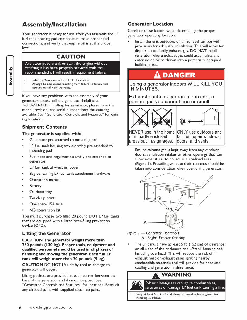
Generator LocationConsider these factors when determining the propergenerator operating location:
• Install the unit outdoors on a flat, level surface withprovisions for adequate ventilation. This will allow fordispersion of deadly exhaust gas. DO NOT installgenerator where exhaust gas could accumulate andenter inside or be drawn into a potentially occupiedbuilding areas.
Ensure exhaust gas is kept away from any windows,doors, ventilation intakes or other openings that canallow exhaust gas to collect in a confined area(Figure 1). Prevailing winds and air currents should betaken into consideration when positioning generator.
• The unit must have at least 5 ft. (152 cm) of clearanceon all sides of the enclosure and LP tank housing pad,including overhead. This will reduce the risk ofexhaust heat or exhaust gases igniting nearbycombustible materials and will provide for adequatecooling and generator maintenance.
6 www.briggsandstratton.com
Assembly/InstallationYour generator is ready for use after you assemble the LPfuel tank housing pad components, make proper fuelconnections, and verify that engine oil is at the properlevel.
If you have any problems with the assembly of yourgenerator, please call the generator helpline at1-800-743-4115. If calling for assistance, please have themodel, revision, and serial number from the data tagavailable. See “Generator Controls and Features” for datatag location.
Shipment ContentsThe generator is supplied with:
• Generator pre-attached to mounting pad
• LP fuel tank housing tray assembly pre-attached tomounting pad
• Fuel hose and regulator assembly pre-attached togenerator
• LP fuel tank all-weather cover
• Bag containing LP fuel tank attachment hardware
• Operator’s manual
• Battery
• Oil drain tray
• Touch-up paint
• One spare 15A fuse
• NG conversion kit
You must purchase two filled 20 pound DOT LP fuel tanksthat are equipped with a listed over-filling preventiondevice (OPD).
Lifting the GeneratorCAUTION The generator weighs more than280 pounds (130 kg). Proper tools, equipment andqualified personnel should be used in all phases ofhandling and moving the generator. Each full LPtank will weigh more than 20 pounds (9 kg).
CAUTION DO NOT lift unit by roof as damage togenerator will occur.
Lifting pockets are provided at each corner between thebase of the generator and its mounting pad. See“Generator Controls and Features” for locations. Retouchany chipped paint with supplied touch-up paint.
• Keep at least 5 ft. (152 cm) clearance on all sides of generatorincluding overhead.
Exhaust heat/gases can ignite combustibles,structures or damage LP fuel tank causing a fire.
WARNING
CAUTION
• Refer to Maintenance for oil fill information.• Damage to equipment resulting from failure to follow this
instruction will void warranty.
Any attempt to crank or start the engine withoutverifying it has been properly serviced with therecommended oil will result in equipment failure.
Figure 1 — Generator ClearancesA - Engine Exhaust Opening
A
Using a generator indoors WILL KILL YOU IN MINUTES. Exhaust contains carbon monoxide, a poison gas you cannot see or smell.
NEVER use in the home or in partly enclosed areas such as garages.
ONLY use outdoors and far from open windows, doors, and vents.
7
• Install the unit in a location where sump pumpdischarge, rain gutter down spouts, roof run-off,landscape irrigation, or water sprinklers will not floodthe unit or spray the enclosure and enter any air inletor outlet openings.
• Install the unit where the location of any services suchas phone, electrical, fuel, air conditioning, irrigation,including covered, concealed and undergroundservices will not be affected or obstructed.
• Install the unit where air inlet and outlet openings willnot become obstructed by leaves, grass, snow, etc. Ifprevailing winds will cause blowing or drifting, youmay need to construct a windbreak to protect theunit.
The generator is shipped already attached to its mountingpad. Unless mandated by local code, a concrete slab is notrequired.
If mandated by local code, construct a concrete slab atleast 3 inches thick and 6 inches longer and wider than thecombined generator and LP tank pad footprint. Attachpads to slab with 1/4” diameter (minimum) masonryanchor bolts.
Attach LP Fuel Tank Housing Pad Parts
Required ToolsYou will need either of the following tools to attach theLP fuel tank housing pad to the generator pad:
• 1/2 inch (13 mm) socket and ratchet OR
• 1/2 inch (13 mm) open end wrench
Attach Mounting Pads Together1. Place LP tank housing pad (with pre-attached LP fuel
tank tray) on the ground next to the side of thegenerator where the fuel hose(s) and regulator areattached.
Confirm that the pre-drilled holes on both mountingpads are adjacent to each other (see Figure 2).
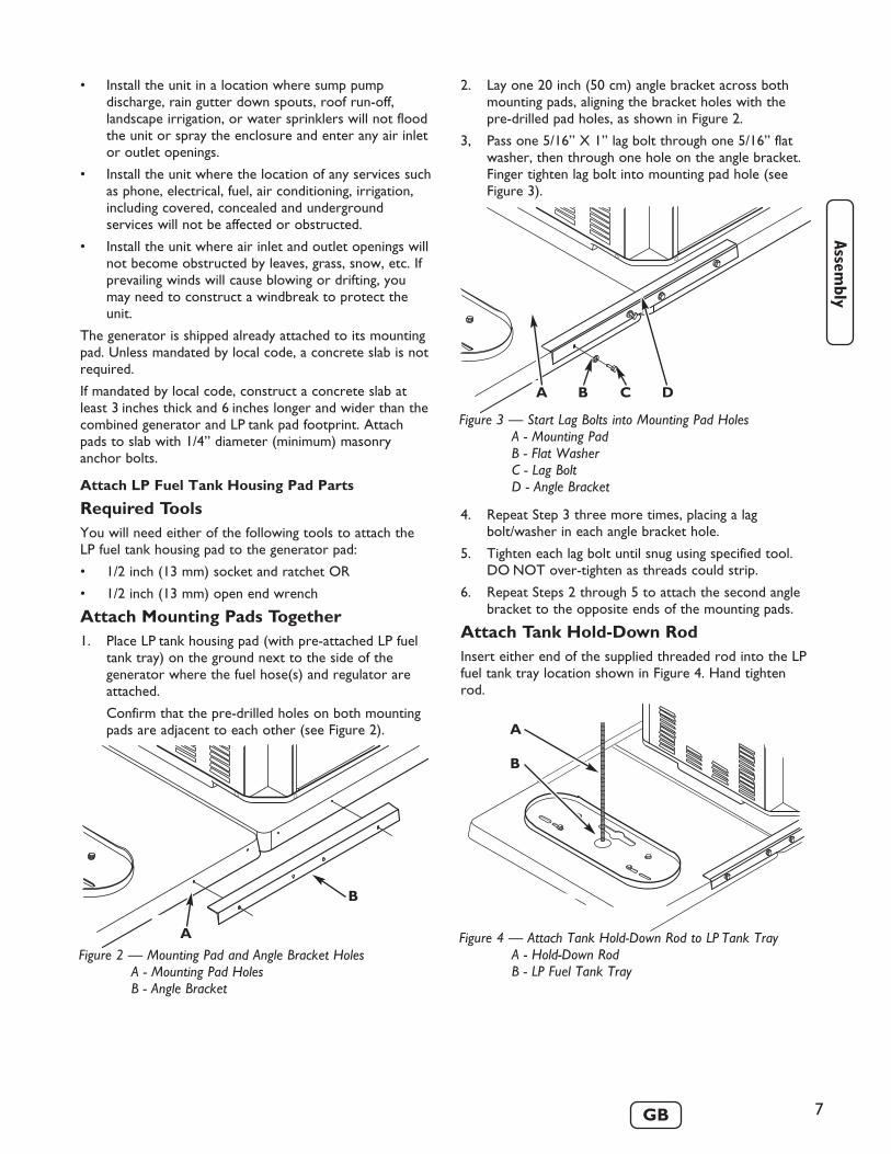
2. Lay one 20 inch (50 cm) angle bracket across bothmounting pads, aligning the bracket holes with thepre-drilled pad holes, as shown in Figure 2.
3, Pass one 5/16” X 1” lag bolt through one 5/16” flatwasher, then through one hole on the angle bracket.Finger tighten lag bolt into mounting pad hole (seeFigure 3).
4. Repeat Step 3 three more times, placing a lagbolt/washer in each angle bracket hole.
5. Tighten each lag bolt until snug using specified tool.DO NOT over-tighten as threads could strip.
6. Repeat Steps 2 through 5 to attach the second anglebracket to the opposite ends of the mounting pads.
Attach Tank Hold-Down RodInsert either end of the supplied threaded rod into the LPfuel tank tray location shown in Figure 4. Hand tightenrod.
Figure 2 — Mounting Pad and Angle Bracket HolesA - Mounting Pad HolesB - Angle Bracket
B
A
Figure 3 — Start Lag Bolts into Mounting Pad HolesA - Mounting PadB - Flat WasherC - Lag BoltD - Angle Bracket
C DBA
Figure 4 — Attach Tank Hold-Down Rod to LP Tank TrayA - Hold-Down RodB - LP Fuel Tank Tray
A
B

8 www.briggsandstratton.com
LP Fuel Tank Installation
IMPORTANT: To ensure optimal performance,use two (2) LP fuel tanks during operation.
This section describes the proper method of installing andleak testing the generator’s LP fuel tanks. This system issupplied with an LP fuel tank cover. Always cover the LPfuel tanks whenever they are connected to the generator.
To Install LP Fuel Tanks:
1. Confirm both LP fuel tank shut off valves are closed(turned fully CLOCKWISE).
2. Place each LP tank into the LP tank tray with it’s fuelvalve pointing towards the generator (see Figure 5).
3. Slide the LP fuel tank hold-down bracket onto thethreaded rod. Position the bracket so that its notchesare aligned with both LP fuel tank collar holes, asshown in Figure 6.
It may be necessary to “wiggle” the LP fuel tanks andthe bracket to obtain proper alignment.
4. Slide the fuel hose/regulator assembly over thethreaded rod so that it faces the generator and restson the hold-down bracket (see Figure 7).
5. Thread the wing nut CLOCKWISE onto the threadedrod. Hand tighten wing nut against fuel hose/regulatorassembly, ensuring hold-down bracket notches remainengaged with LP fuel tank collars and LP fuel tanks areheld firmly. See Figure 8.
6. Remove protective covers from both LP fuel tank shutoff valve connectors. DO NOT discard protectivecovers - they should be installed any time the LP fueltank is disconnected from the generator.
7. Insert the nipple of the left connection device (as youface the generator and LP fuel tanks) into the left LPfuel tank valve outlet (see Figure 9). Ensure it is fullyinserted.
• The slightest spark can ignite this fuel and cause an explosion.• IF YOU SMELL GAS - Shut off gas to the generator at the LP fuel
tank(s).• If odor continues, leave the area and immediately call your gas
supplier or fire department.
Propane Gas is extremely flammable andexplosive.Fire or explosion can cause severe burns ordeath.
WARNING
Figure 5 — Proper Position for LP Fuel TanksA - LP Fuel Tank Shut Off Valve ConnectorB - LP Fuel Tank
B
A
Figure 6 — Properly-Aligned Hold-Down BracketA - Bracket Notch over Fuel Tank CollarB - Hold-Down Bracket
BA
Figure 7 — Fuel Hose/Regulator Assembly PlacementA - Hold-Down BracketB - Threaded RodC - Fuel Hose/Regulator Assembly
A B C
Figure 8 — Properly-Secured LP Fuel TanksA - LP Fuel TankB - Wing NutC - Fuel Hose/Regulator Assembly
A
B
C

3. Using a sponge, rag or small non-metallic brush, applythe soap water mixture at each of the locationsshown in Figure 10 below.
4. Check each location shown in Figure 10 for growingbubbles, which indicates a fuel leak. Bubbles will looksomething like this:
5. Close both LP fuel tank shut off valves (turn fullyCLOCKWISE).
6. Press and hold control panel’s START/RUN/STOPswitch in START position for 5 seconds to release gaspressure in hoses. See “Control Panel Controls andFeatures”.
7. Tighten or replace any leaking connections.
9
8. Turn the large coupling nut CLOCKWISE and handtighten to a full stop.DO NOT cross thread the connection.DO NOT use thread sealant.DO NOT over-tighten the coupling nut.DO NOT use tools to tighten the connection.
NOTE: If you are unable to make the connection, repeatStep 7 or contact an LP fuel professional.
9. Repeat Steps 7 and 8 to attach the right LP fuel tank.
10. Confirm that each fuel hose does not have kinks andthat it does not touch sharp edges or surfaces thatmay become hot during generator operation.
11. Perform a complete fuel leak test, using theinstructions given in “Leak Testing Fuel System”.
Leak Testing Fuel System1. Create a mixture of 50% water and 50% liquid
dishwashing soap.
2. Turn ON the fuel supply by turning both LP fuel tankshut off valves one full turn COUNTERCLOCKWISE.
Figure 10 — Leak Test LocationsA - LP Fuel Tank WeldsB - LP Fuel Tank Shut Off Valves at Cylinder
ConnectionsC - Both Coupling Nuts to LP Fuel Tank Shut Off Valve
Connections
D - Back Sides of Coupling Nuts and Hose ConnectionJoints
E - Brass T-Valve Connections (all joints)F - Regulator Connection to Fuel HoseG - The Full Length of all Fuel HosesH - Fuel Hose Connection to Generator (all joints)
A
D
B G H
G
E
F
E
C D
G
B G
• DO NOT smoke or permit ignition sources in the area whileconducting a leak test.
• Perform leak test OUTDOORS only in a well ventilated area.• DO NOT perform a leak test with a match or open flame.• DO NOT perform a leak test while the generator is in use.• ALWAYS perform a leak test when first using the generator.• ALWAYS perform a leak test every time an LP fuel tank or any
fuel system component is changed.• ALWAYS perform a leak test whenever the generator is moved.• Perform a leak test at least once per year or if your generator has
not been used for more than 60 days.
Propane Gas is extremely flammable andexplosive.Fire or explosion can cause severe burns ordeath.
WARNING
Figure 9 — Proper Connection Device AlignmentA - Fuel Hose Connector NippleB - LP Fuel Tank Shut Off Valve Connector
B
A

10 www.briggsandstratton.com
8. Repeat Steps 2 through 7 until no leaks are detected.DO NOT use the generator if leaks cannot bestopped. Contact a qualified LP fuel professional forassistance.
9, Turn OFF both LP fuel tank shut off valves until youare ready to use the generator.
10. Wash off soapy residue with clean cold water andtowel dry.
11. Wait five minutes to allow all gas to evacuate the areabefore starting the generator.
NOTE: The leak test must be performed in an area thathas adequate lighting in order to see if bubbles aredeveloping. DO NOT use a flashlight to check for bubbles.
To Remove LP Fuel Tank(s)1. Confirm the LP fuel tank shut off valve is closed
(turned fully CLOCKWISE).
2. Disconnect the fuel hose from the LP tank by turningthe large coupling nut COUNTERCLOCKWISE byhand (see Figure 9).
3. Install the protective cover over the LP fuel tank shutoff valve outlet.
4. Remove wing nut from threaded rod by turning itCOUNTERCLOCKWISE. Lift and remove the fuelhose/regulator assembly from the threaded rod. SeeFigures 7 and 8.
5. Lift and remove the LP tank hold-down bracket fromthreaded rod (see Figure 6). It may be necessary towiggle the LP fuel tanks to release the hold-downbracket.
6. Carefully lift the LP fuel tank off the LP fuel tank tray.
Verify Engine Oil Level
The generator engine is shipped from the factory filledwith synthetic oil (API SJ/CF 5W-30W). This allows forgenerator operation in the widest range of temperatureand climate conditions. Before starting the engine, checkoil level and ensure that engine is serviced as described in“Maintenance”.
NOTE: The use of synthetic oil does not alter therequired oil change intervals described in theMaintenance section.
Removable Roof and Access DoorThe generator enclosure includes a removable roof andbattery access door.
To Remove Roof:
There are two screws on each side of the roof located inthe half-moon roof slots. Remove the four screws and liftroof off.
To Remove Battery Access Door:
1. Disconnect any loads connected to the generator.
2. Remove roof as described above.
3. Remove screw at top of access door.
4. Pull access door outward (away) from unit whilepulling door upward and out of base.
Door will come free of generator enclosure.
To Install Battery Access Door and Roof:
1. Guide bottom of access door into base.
2. Push access door in until it is flush with sides.
3. Replace door screw.
4. Replace roof and four roof screws.
Battery Connection
The generator is supplied with a sealed, lead-acidrechargeable 12 Volt DC, AGM type, 33 Amp-Hour,battery. The battery cables are connected at the factory.
The battery will lose some charge in shipping and prior togenerator installation. If battery voltage is too low to startthe engine, charge the battery, as described in“Maintenance”.
If the battery fails to take a charge, it must be replacedONLY with the same type of 12 Volt DC, AGM type,33 Amp-Hour battery. DO NOT replace with liquidelectrolyte lead-acid type battery.
CAUTION
• Refer to Maintenance for oil fill information.• Damage to equipment resulting from failure to follow this
instruction will void warranty.
Any attempt to crank or start the engine withoutverifying it has been properly serviced with therecommended oil will result in equipment failure.
• DO NOT dispose of battery in a fire.• DO NOT allow any open flame, spark, heat, or lit cigarette during
and for several minutes after charging a battery.• DO NOT open or mutilate the battery.• Wear protective goggles, rubber apron, and rubber gloves.• Remove watches, rings, or other metal objects.• Use tools with insulated handles.
Storage batteries give off explosive hydrogengas during recharging.Slightest spark will ignite hydrogen and causeexplosion.Battery electrolyte fluid contains acid and isextremely acidic.Contact with battery contents will cause severechemical burns.A battery presents a risk of electrical shock andhigh short circuit current.
DANGER

11
Generator Controls and FeaturesRead this Operator’s Manual and safety rules before operating your generator.Compare the illustrations with your generator, to familiarize yourself with the locations of various controls andadjustments. Save this manual for future reference.
Generator is shown with roof, oil filter access door, battery access door and control panel cover removed.
See Figures 5 through 8, earlier, for important LP fuel tank component views.
N
A
M
GL
K H
CB
E
D
F
A - Engine Model Number Identification — (stampedon top of valve cover) Identifies engine model and type.
B - Rotating Screen — Prevents large debris fromentering engine cooling airflow stream.
C - Oil Fill Cap/Dipstick — Check and fill engine withrecommended oil here.D - Control Panel — Used for various operation andmaintenance functions. See “Control Panel Controls andFeatures” on next page.
E - Oil Drain Hose — Provided to facilitate oil changing.
F - Unit Data Decal — Displays model, revision andserial numbers.G - Battery — 12 Volt DC, 33 Amp-Hour, sealed batteryprovides power to start engine. Battery receives tricklecharge whenever generator is running.
H - Equipment Grounding Terminal — Connectgenerator to earth ground here.
K - Lifting Pockets — Provided at each lower cornerfor lifting generator and attached pad.
L - Fuel Inlet — Fuel supply components are attached togenerator here.
M - Exhaust Port — High-performance muffler lowersengine noise to comply with most residential codes.Includes approved spark arrester.
N - Oil Filter — Filters engine oil to prolong generatorlife.
P - Hazard/Start/Stop Instructions — Observe thesewarnings and procedures when operating generator.
R - Air Cleaner — Uses a dry type filter element andfoam precleaner to protect engine by filtering dust anddebris out of intake air.
R
P
12 www.briggsandstratton.com
GFCIMAIN BREAKER
PUSHTO
RESET
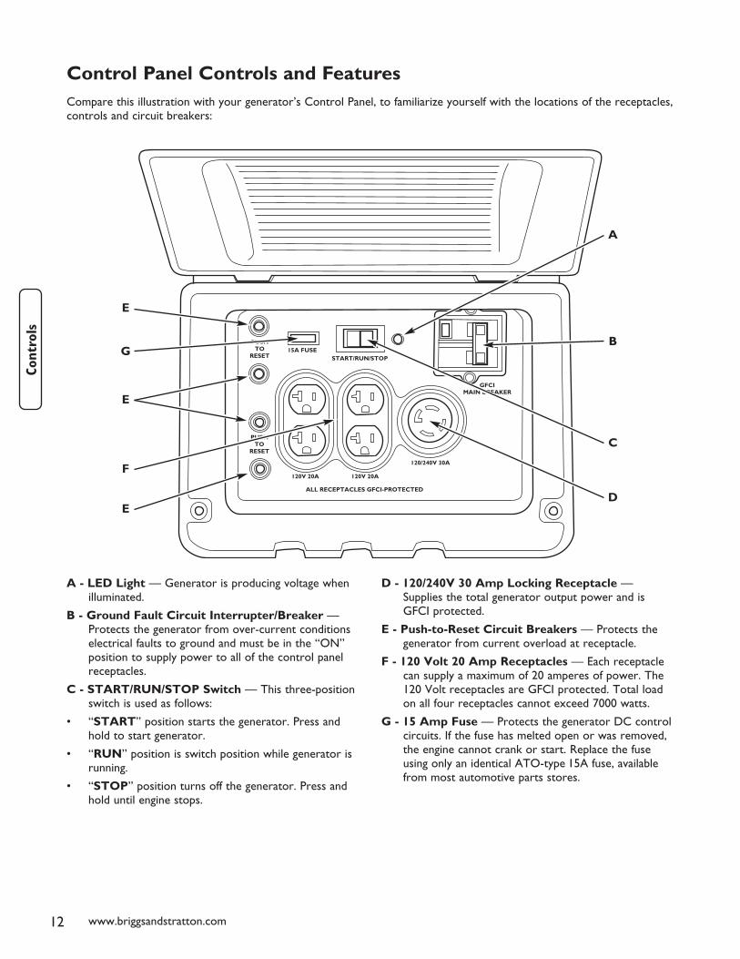
Control Panel Controls and FeaturesCompare this illustration with your generator’s Control Panel, to familiarize yourself with the locations of the receptacles,controls and circuit breakers:
A - LED Light — Generator is producing voltage whenilluminated.
B - Ground Fault Circuit Interrupter/Breaker —Protects the generator from over-current conditionselectrical faults to ground and must be in the “ON”position to supply power to all of the control panelreceptacles.
C - START/RUN/STOP Switch — This three-positionswitch is used as follows:
• “START” position starts the generator. Press andhold to start generator.
• “RUN” position is switch position while generator isrunning.
• “STOP” position turns off the generator. Press andhold until engine stops.
D - 120/240V 30 Amp Locking Receptacle —Supplies the total generator output power and isGFCI protected.
E - Push-to-Reset Circuit Breakers — Protects thegenerator from current overload at receptacle.
F - 120 Volt 20 Amp Receptacles — Each receptaclecan supply a maximum of 20 amperes of power. The120 Volt receptacles are GFCI protected. Total loadon all four receptacles cannot exceed 7000 watts.
G - 15 Amp Fuse — Protects the generator DC controlcircuits. If the fuse has melted open or was removed,the engine cannot crank or start. Replace the fuseusing only an identical ATO-type 15A fuse, availablefrom most automotive parts stores.
120/240V 30A
G
C
A
E
E
E
F
D
BPUSHTO
RESET
120V 20A
ALL RECEPTACLES GFCI-PROTECTED
120V 20A
15A FUSESTART/RUN/STOP

13
Receptacles
120/240 Volt AC, 30 Amp, LockingReceptacleThis receptacle (Figure 11) supplies the entire generatoroutput and is protected against overload by a double-poleGFCI circuit breaker.
Use a NEMA L14–30 plug with this receptacle. Connect a4–wire cord set rated for 250 Volt AC loads at 30 Amps(or greater). You can use the same 4–wire cord if youplan to run a 120 Volt load. Inspect cord set(s) beforeeach use. Store cord set(s) indoors.
When operating on LP fuel, this receptacle powers120/240 Volt AC, 60 Hz, single phase loads requiring upto 7,000 watts of power (7.0 kW) at 29.16 Amps for240 Volts or two independent 120 Volt loads at29.16 Amps each.
120 Volt AC, 20 Amp, Duplex ReceptaclesEach individual duplex receptacle (Figure 12) is protectedagainst overload by a push-to-reset circuit breaker. Allfour receptacles are also protected by a double-pole GFCIcircuit breaker.
Use each receptacle to operate 120 Volt AC,single–phase, 60 Hz electrical loads requiring up to2,400 watts (2.4 kW) at 20 Amps of current whenoperating on LP fuel. Use cord sets that are rated for125 Volt AC loads at 20 Amps (or greater). Inspect cordset(s) before each use.
NOTE: Follow all safety precautions when connecting anyextension cord or device to the generator.
Equipment GroundThe generator is equipped with an equipment groundingterminal that connects the generator frame componentsto the ground terminals on the AC output receptacles.Ground the generator per applicable codes, standards, andregulations.
The equipment ground is connected to the AC neutralwire and the neutral is bonded to the generator frame.The equipment grounding terminal is shown on“Generator Controls and Features”.
Special Requirements
There may be Federal or State Occupational Safety andHealth Administration (OSHA) regulations, local codes, orordinances that apply to the intended use of thegenerator. Please consult a qualified electrician, electricalinspector, or the local agency having jurisdiction.
• In some areas, generators are required to beregistered with local utility companies.
• If the generator is used at a construction site, theremay be additional regulations which must beobserved.
• NEVER attempt to power a device requiring more amperage thangenerator or receptacle can supply.
• DO NOT overload the generator. See “Don’t OverloadGenerator”.
Receptacles may be marked with rating value greaterthan generator output capacity.
CAUTION
• See “Don’t Overload Generator”.• Start generator and let engine stabilize before connecting electrical
loads.• Connect electrical loads in OFF position, then turn ON for
operation.• Turn electrical loads OFF and disconnect from generator before
stopping generator.
Exceeding generators wattage/amperage capacity candamage generator and/or electrical devices connectedto it.
CAUTION
Figure 11 — 120/240 Volt AC, 30 Amp Receptacle
4-Wire Cord Set
240V
120V 120VW (Neutral)
X (Hot)Y (Hot)
NEMA L14-30 Ground (Green)
Figure 12 — 120 Volt, 20 Amp Duplex Receptacle

14 www.briggsandstratton.com
Operating Your Generator
Starting the EngineUse the following start instructions:
1. Make sure unit is on a flat, level surface.
IMPORTANT: Failure to start and operate unit on alevel surface will cause the unit not to start or shut downduring operation.
2. Open control panel cover using standard screwdriver.
3. Disconnect all load(s) to generator.
4. Open LP tank fuel shut off valve(s).
5. Confirm 15 Amp fuse is installed in control panel.
6. Push and hold START/RUN/STOP switch in STARTposition until engine starts and control panel LED isON.
IMPORTANT: If you release the switch from theSTART position before red LED comes on, the generatorwill shut down.
NOTE: DO NOT crank engine for more than15 seconds, then pause for 15 seconds to reduce heat instarter. Repeat start process until engine starts.
NOTE: When starting generator, air may be present inthe fuel line(s), especially after changing fuel tanks. It maytake several starting cycles to purge that air before theengine will start.
Connecting Electrical Loads1. Let engine run for two minutes after starting.
2. Open control panel cover and confirm generator’smain circuit breaker is in the ON (closed) position.See “Control Panel Controls and Features”.
3. Plug in, then turn on the desired 120 and/or 240 VoltAC, single phase, 60 Hz electrical loads.
3. Close and latch control panel cover.
IMPORTANT:
• DO NOT connect 240 Volt loads to the 120 Voltduplex receptacles.
• DO NOT connect 3–phase loads to the generator.
• DO NOT connect 50 Hz loads to the generator.
• DO NOT OVERLOAD THE GENERATOR. See“Don’t Overload Generator”.
Stopping the Engine1. Open control panel cover using standard screwdriver.
2. Turn OFF all electrical loads. Disconnect them fromcontrol panel receptacles.
Never start or stop engine with electrical devicesplugged in and turned on.
3. Let engine run for two minutes with no loads tostabilize internal temperatures of engine andgenerator.
4. Push and hold START/RUN/STOP switch in STOPposition until LED turns off and engine stops.
5. Close manual fuel shut off valve(s).
6. Close and latch control panel cover.
These steps should be performed after the generator has beenassembled, stored, moved, cleaned, or repaired. DO NOT operate thisgenerator until you have read and understand ALL of the warnings andinstructions in this operator’s manual.
• Insure that the generator is properly assembled.• Inspect the LP fuel supply hoses for burns, chaffing, kinks, and
proper routing before each use. Hoses should be kept at least3 inches (8 cm) away from hot surfaces.
• Leak test all LP fuel connections and and hoses. See “Leak TestingFuel System”.
• Position your generator on level ground in a well ventilatedlocation, 5 feet (152 cm) away from combustible materials andbuildings, including overhead. DO NOT use generator on woodendecks or other surfaces that could burn.
Propane Gas is extremely flammable andexplosive.Fire or explosion can cause severe burns ordeath.
WARNING
• DO NOT touch hot surfaces and avoid hot exhaust gases.• Allow equipment to cool before touching.• Keep at least 5 ft. (152 cm) clearance on all sides of generator
including overhead.
Running engines produce heat. Temperature ofmuffler and nearby areas can reach or exceed150°F (65°C).Severe burns can occur on contact.Exhaust heat/gases can ignite combustibles,structures or damage LP fuel tank causing a fire.
WARNING

15
Ground Fault ProtectionThis unit is equipped with a Ground Fault CircuitInterrupter (GFCI). This device meets applicable federal,state and local codes.
Test GFCI Circuit Breaker
Test your GFCI circuit breaker (see “Control PanelControls and Features” for location) every month, asfollows:
1. While generator is running and control panel coveropen, push white “Test” button. The circuit breakershould trip (handle will move to approximate centerposition), which will disconnect power to outlets.
2. If handle moves to center, reset circuit breaker byfirmly moving handle to “Off” (left) position, then to“On” (right) position.
During Generator Use
If circuit breaker trips during use, it usually indicates faultyelectrical equipment or cords. However, test the circuitbreaker as follows;
1. Open control panel cover, disconnect loads, reset andtest circuit breaker as described earlier. Let generatorrun without any loads for 1 minute.
2. If circuit breaker tests correctly, the electricalequipment or extension cords may be faulty. Replacefaulty electrical equipment and cords before furtheruse.• DO NOT use generator.
• Call a Briggs & Stratton Power Products service center.
If circuit breaker does not trip:
CAUTION
• DO NOT use generator.• Call a Briggs & Stratton Power Products service center.
If circuit breaker does not reset properly:
CAUTION
• DO NOT use generator.• Call a Briggs & Stratton Power Products service center.
If circuit breaker trips in the 1 minute period:
CAUTION
• Have qualified personnel check all electrical equipment and cordsfor any defects.
• Replace electrical equipment and cords or take to a qualifiedrepair center.
If circuit breaker tests correctly:
CAUTION

16 www.briggsandstratton.com
Don’t Overload GeneratorCapacity
You must make sure your generator can supply enoughrated (running) and surge (starting) watts for the itemsyou will power at the same time. Follow these simplesteps:
1. Select the items you will power at the same time.
2. Total the rated (running) watts of these items. This isthe amount of power your generator must produceto keep your items running. See Figure 13.
3. Estimate how many surge (starting) watts you willneed. Surge wattage is the short burst of powerneeded to start electric motor-driven tools orappliances such as a circular saw or refrigerator.Because not all motors start at the same time, totalsurge watts can be estimated by adding only theitem(s) with the highest additional surge watts to thetotal rated watts from step 2.
Example:
Total Rated (Running) Watts = 3075
Highest Additional Surge Watts = 1800
Total Generator Output Required = 4875
Power Management
To prolong the life of your generator and attacheddevices, it is important to take care when adding electricalloads to your generator. There should be nothingconnected to the generator outlets before starting it'sengine. The correct and safe way to manage generatorpower is to sequentially add loads as follows:
1. With nothing connected to the generator, start theengine as described in this manual.
2. Plug in and turn on the first load, preferably thelargest load you have.
3. Permit the generator output to stabilize (engine runssmoothly and attached device operates properly).
4. Plug in and turn on the next load.
5. Again, permit the generator to stabilize.
6. Repeat steps 4 and 5 for each additional load.
Never add more loads than the generator capacity.Take special care to consider surge loads ingenerator capacity, as described above.
*Wattages listed are approximate only. Check tool orappliance for actual wattage.
Figure 13 — Wattage Reference Guide
Tool or Appliance Rated*
(Running) Watts
Additional Surge
(Starting) Watts
Essentials Light Bulb - 75 watt 75 - Deep Freezer 500 500 Sump Pump 800 1200 Refrigerator/Freezer - 18 Cu. Ft. 800 1600 Water Well Pump - 1/3 HP 1000 2000 Heating/Cooling Window AC - 10,000 BTU 1200 1800 Window Fan 300 600 Furnace Fan Blower - 1/2 HP 800 1300 Kitchen Microwave Oven - 1000 Watt 1000 - Coffee Maker 1500 - Electric Stove - Single Element 1500 - Hot Plate 2500 - Family Room DVD/CD Player 100 - VCR 100 - Stereo Receiver 450 - Color Television - 27” 500 - Personal Computer w/17” monitor 800 - Other Security System 180 - AM/FM Clock Radio 300 - Garage Door Opener - 1/2 HP 480 520 Electric Water Heater - 40 Gallon 4000 - DIY/Job Site Quartz Halogen Work Light 1000 - Airless Sprayer - 1/3 HP 600 1200 Reciprocating Saw 960 960 Electric Drill - 1/2 HP 1000 1000 Circular Saw - 7 1/4” 1500 1500 Miter Saw - 10” 1800 1800 Table Planer - 6” 1800 1800 Table Saw/Radial Arm Saw - 10” 2000 2000 Air Compressor - 1-1/2 HP 2500 2500

17
Maintenance ScheduleFollow the hourly or calendar intervals, whichever occurs first.
More frequent service is required when operating in adverse conditions noted below.
General RecommendationsRegular maintenance will improve the performance andextend the life of the generator. See any authorized Briggs& Stratton dealer for service. Never operate adamaged or defective generator. To receive full valuefrom the warranty, the operator must maintain thegenerator as instructed in this section.
All service and adjustments should be made at least onceeach season. Follow the requirements in the “MaintenanceSchedule” chart above.
NOTE: Once a year you should clean or replace thespark plug and replace the air filter. A new spark plug andclean air filter assure proper fuel-air mixture and helpyour engine run better and last longer.
NOTE: The alternator assembly rotates on aprelubricated and sealed ball bearing that requires noadditional lubrication for the life of the bearing.
Emissions ControlMaintenance, replacement or repair of the emissionscontrol devices and systems may be performed by anynon-road engine repair establishment or individual. See“Emissions Control System Warranty”.
MaintenanceMaintenance consists of keeping the unit clean. Operatethe unit in an environment where it will not be exposedto excessive dust, dirt, moisture or any corrosive vapors.Cooling air louvers on the enclosure must not becomeclogged with snow, leaves, or any other foreign material.Inspect cooling air slots and openings on generator. Theseopenings must be kept clean and unobstructed.
Check the cleanliness of the unit frequently and cleanwhen dust, dirt, oil, moisture or other foreign substancesare visible on its exterior/interior surface.
NOTE: DO NOT use direct spray from a garden hose toclean generator. Water can enter the engine andgenerator and cause problems.
Clean Debris• Use a damp cloth to wipe exterior surfaces clean.
• Use a soft bristle brush to loosen caked on dirt or oil.
• Use a vacuum cleaner to pick up loose dirt anddebris.
1 Change oil sooner when operating under dirty or dusty conditions.2 Replace more often under dirty or dusty conditions.3 Check yearly only.4 Clean more often under dirty or dusty conditions.5 Replace every five years.
MAINTENANCE SCHEDULEFILL IN DATES AS YOU
COMPLETE REGULAR SERVICESERVICE DATES
SERVICE DATES
MAINTENANCE TASK BeforeEach Use
Every 25 Hoursor Yearly
Every 50 Hoursor Yearly
Every 100 Hoursor Yearly
Clean debris X
Check oil level X
Change engine oil X1
Change oil filter X
Service air cleaner pre-cleaner X²
Replace air cleaner cartridge X²
Replace spark plug X
Check valve clearance X3
Clean cooling system X4
Replace fuel hoses and regulator X5

18 www.briggsandstratton.com
Engine parts should be kept clean to reduce the risk ofoverheating and ignition of accumulated debris. Use thesame instructions given above for the engine.
OilOil Recommendations
NOTE: When adding oil to the engine crankcase, useonly high quality detergent oil classified “For Service SF,SG, SH, SJ” or higher. DO NOT use special additives.
1. Choose a viscosity according to the following table:
*Check oil level frequently at higher temperatures.NOTE: Synthetic oil meeting ILSAC GF-2, APIcertification mark and API service symbol with “SJ/CFENERGY CONSERVING” or higher, is an acceptable oil atall temperatures. Use of synthetic oil does not alterrequired oil change intervals.
SAE 30: 40 °F and higher (5 °C and higher) is good for allpurpose use above 40°F, use below 40°F will cause hardstarting.
10W-30: 0 to 100 °F (-18 to 38 °C) is better for varyingtemperature conditions. This grade of oil improves coldweather starting, but may increase oil consumption at80°F (27°C) or higher.
Synthetic 5W-30: -20 to 120 °F (-30 to 40 °C) providesthe best protection at all temperatures as well asimproved starting with less oil consumption.
5W-30: 40 °F and below (5 °C and below) isrecommended for winter use, and works best in coldconditions.
Checking and Adding Oil
Oil level should be checked prior to each use or at leastevery 8 hours of operation. Keep oil level maintained.
1. Make sure unit is on a level surface.
2. Remove roof (see Removable Roof and BatteryAccess section).
3. Remove oil fill cap/dipstick and wipe clean with cloth.
4. Verify oil level is at the FULL mark on dipstick(Figure 14).
5. If needed, slowly pour oil into oil fill opening.RECHECK oil level. DO NOT overfill.
6. Replace and tighten dipstick.
7. Replace roof.
Changing Engine Oil and Filter
Remove the two screws from each plastic access coverand remove both access covers from the two sides of thegenerator enclosure.
Changing Oil
1. Slide oil drain tube from hose clamp and place oildrain tube into approved container.
2. Push in and rotate oil drain fitting 1/4 turncounterclockwise. Slowly pull outward until oil startsdraining (Figure 15). DO NOT pull oil drain fittingoff.
Figure 15 — Oil Drain Fitting
Figure 14 — Oil Fill Range
• DO NOT expose generator to excessive moisture, dust, dirt, orcorrosive vapors.
• DO NOT insert any objects through cooling slots.
Improper treatment of generator can damage it andshorten its life.
CAUTION

19
Service Air Cleaner ElementsYour engine will not run properly and may be damaged ifyou run it with dirty air cleaner elements.
• Replace the air cleaner pre-cleaner every 25 hoursof operation or once each year, whichever comesfirst.
• Replace the air cleaner cartridge every 100 hours ofoperation or once each year. This air filter is ULapproved flame retardant material. Replace air filtercartridge with original equipment replacement part.
• Replace more often if operating under dirty or dustyconditions.
To service the air cleaner elements, follow thesesteps:
1. Remove generator roof, as described in “RemovableRoof and Battery Access”.
2. Pull up on air cleaner cover handle and rotate towardengine.
3. Remove air cleaner cover.
4. Carefully lift air cleaner cartridge and pre-cleanerfrom housing. Figure 17 shows the air cleaner housingarea.
NOTE: To clean pre-cleaner, wash in soapy water.Squeeze dry in a clean cloth. DO NOT wring. DONOT oil.
5. Vacuum air cleaner housing area carefully to preventdebris from entering engine.
6. To clean cartridge, gently tap pleated paper side on aflat surface.
3. When oil has drained, push oil drain fitting in androtate 1/4 turn clockwise until it locks in place.
4. Slide oil drain tube up into clamp on generator.
KEEP OUT OF REACH OF CHILDREN.DON'T POLLUTE. CONSERVERESOURCES. RETURN USED OIL TOCOLLECTION CENTERS.
Changing Oil Filter
1. Place oil drain tray over tubing and slide it under oilfilter (Figure 16).
2. Grasp oil filter by hand and rotate counterclockwise.Filter should detach from generator.
3. Before installing new filter, lightly oil filter gasket withfresh, clean engine oil.
4. Carefully screw filter on until gasket contacts oil filteradapter. Tighten by hand 1/2 to 3/4 turn more.
5. Remove oil drain tray from under oil filter and cleanup any spilled oil.
Fill engine with oil:
1. Add fresh recommended oil. Fill to FULL line ondipstick.
2. Start and run generator for two minutes with noloads connected and check for oil leaks.
3. Stop engine. Recheck oil level and add oil if required.DO NOT overfill.
Figure 17 — Changing Air Filter ElementsA - Air cleaner housingB - Air cleaner cartridgeC - Air cleaner pre-cleanerD - Air cleaner cover
• Used motor oil has been shown to cause skin cancer in certainlaboratory animals.
• Thoroughly wash exposed areas with soap and water.
Avoid prolonged or repeated skin contact with usedmotor oil.
CAUTION
A B
C
D
Figure 16 — Changing Oil Filter with Oil Drain TrayA - Oil drain tray placement
A
20 www.briggsandstratton.com
IMPORTANT: DO NOT use pressurized air or solventsto clean cartridge. Pressurized air can damage cartridge;solvents will dissolve cartridge.
7. Place air cleaner pre-cleaner and cartridge intohousing. Cartridge must fit securely in housing.
8. Align tabs on cover with slots in housing and replacecover.
9. Hook handle and close cover.
10. Replace roof.
Service Spark Plug
Change the spark plug every 100 hours of operation oronce each year, whichever comes first. This will help yourengine to start easier and run better.
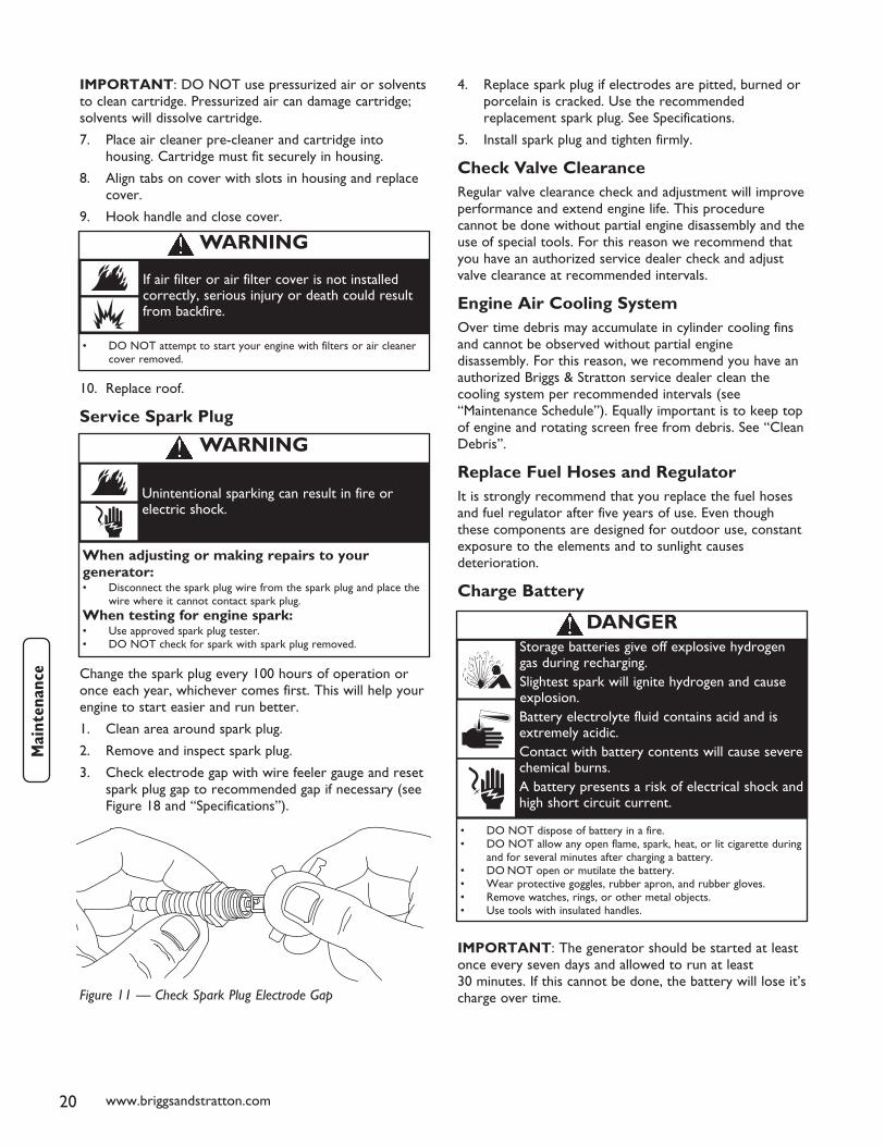
1. Clean area around spark plug.
2. Remove and inspect spark plug.
3. Check electrode gap with wire feeler gauge and resetspark plug gap to recommended gap if necessary (seeFigure 18 and “Specifications”).
4. Replace spark plug if electrodes are pitted, burned orporcelain is cracked. Use the recommendedreplacement spark plug. See Specifications.
5. Install spark plug and tighten firmly.
Check Valve ClearanceRegular valve clearance check and adjustment will improveperformance and extend engine life. This procedurecannot be done without partial engine disassembly and theuse of special tools. For this reason we recommend thatyou have an authorized service dealer check and adjustvalve clearance at recommended intervals.
Engine Air Cooling SystemOver time debris may accumulate in cylinder cooling finsand cannot be observed without partial enginedisassembly. For this reason, we recommend you have anauthorized Briggs & Stratton service dealer clean thecooling system per recommended intervals (see“Maintenance Schedule”). Equally important is to keep topof engine and rotating screen free from debris. See “CleanDebris”.
Replace Fuel Hoses and RegulatorIt is strongly recommend that you replace the fuel hosesand fuel regulator after five years of use. Even thoughthese components are designed for outdoor use, constantexposure to the elements and to sunlight causesdeterioration.
Charge Battery
IMPORTANT: The generator should be started at leastonce every seven days and allowed to run at least30 minutes. If this cannot be done, the battery will lose it’scharge over time.Figure 11 — Check Spark Plug Electrode Gap
When adjusting or making repairs to yourgenerator:• Disconnect the spark plug wire from the spark plug and place the
wire where it cannot contact spark plug.When testing for engine spark:• Use approved spark plug tester.• DO NOT check for spark with spark plug removed.
Unintentional sparking can result in fire orelectric shock.
WARNING
• DO NOT attempt to start your engine with filters or air cleanercover removed.
If air filter or air filter cover is not installedcorrectly, serious injury or death could resultfrom backfire.
WARNING
• DO NOT dispose of battery in a fire.• DO NOT allow any open flame, spark, heat, or lit cigarette during
and for several minutes after charging a battery.• DO NOT open or mutilate the battery.• Wear protective goggles, rubber apron, and rubber gloves.• Remove watches, rings, or other metal objects.• Use tools with insulated handles.
Storage batteries give off explosive hydrogengas during recharging.Slightest spark will ignite hydrogen and causeexplosion.Battery electrolyte fluid contains acid and isextremely acidic.Contact with battery contents will cause severechemical burns.A battery presents a risk of electrical shock andhigh short circuit current.
DANGER

21
Service BatteryIf it is necessary to service the battery, proceed as follows:
1. Open control panel cover.
2. Remove the 15 Amp fuse from the control panelusing the fuse removal tool.
3. Disconnect the negative battery cable, thendisconnect the positive battery cable.
4. Service or replace battery as required.
5. Connect the red battery cable to the battery positiveterminal (indicated by POSITIVE, POS, or (+)).
6. Connect the negative battery cable to the negativebattery terminal (indicated by NEGATIVE, NEG, or(-)).
7. Ensure hardware on both positive and negativebattery terminals is secure.
8. Reinstall the 15 Amp fuse in the control panel.
Generator is now ready for starting and use.
StorageThe generator should be started at least once every sevendays and allowed to run at least 30 minutes. If this cannotbe done and you must store the unit for more than30 days, use the following guidelines to prepare it forstorage:
1. While engine is still warm, change oil as describedearlier in “Changing Engine Oil and Filter”.
2. Remove spark plug and pour about 1 oz. (30 ml) ofengine oil into cylinder. Replace spark plug butDO NOT connect spark plug wire.
3. Ensure fuel supply shut off valve is closed.
4. Press START/RUN/STOP switch momentarily todistribute oil.
5. Connect spark plug wire to spark plug.
6. Clean the generator as outlined in “GeneratorCleaning”. Ensure that cooling air slots and openingson generator are open and unobstructed.
7. Charge the battery, as described in “Charge Battery”.
8. If the generator is subjected to freezing temperatures,disconnect battery cables from battery and move it toa warmer location. Charge the battery before thenext season’s use.
If the generator is not operated once a month, the batteryshould be removed and trickle charged regularly in orderto keep the battery charged and ready to start thegenerator when needed. If battery voltage is too low, thebattery may not take a charge and you will need a newbattery.
If it is necessary to charge the battery, proceed as follows:
1. Open control panel cover.
2. Using the supplied fuse removal tool, remove the15 Amp fuse from the control panel.
3. Disconnect the negative battery cable from thenegative battery terminal (indicated by NEGATIVE,NEG, or (-).
4. Charge battery with battery charger set at 2 Ampsuntil full charge is indicated by battery charger.
IMPORTANT: If the battery fails to take a charge, itmust be replaced with the same type of 12 Volt DC,AGM type, 33 Amp-Hour, battery. DO NOT replace withliquid electrolyte lead-acid type battery.
5. Connect the negative battery cable to the negativebattery terminal (indicated by NEGATIVE, NEG, or(-)).
6. Ensure hardware on both positive and negativebattery terminals is secure.
7. Reinstall the 15 Amp fuse in the control panel.
Generator is now ready for starting and use.
CAUTION
• DO NOT attempt to jump start the battery.• Damage to equipment resulting from failure to follow this
instruction will void warranty.
Failure to disconnect negative battery cable will resultin equipment failure.
• DO NOT charge at a rate more than 2 Amps.• Wear protective goggles, rubber apron, and rubber gloves.
Overcharging will cause the battery case tocrack and battery electrolyte to spill.Battery electrolyte fluid contains acid and isextremely acidic.Contact with battery contents will cause severechemical burns.
WARNING

22 www.briggsandstratton.com
Notes
Troubleshooting
Problem Cause Correction
Engine is running, but no ACoutput is available.
1. Circuit breaker open or defective.
2. Fault in generator.
1. Reset or replace circuit breaker.
2. Contact local service facility.
Engine runs good at no-load but"bogs down" when loads areconnected.
1. Short circuit in a connected load.
2. Generator is overloaded.
3. Shorted generator circuit.
4. Fuel pressure is incorrect.
5. LP fuel mixture is incorrect.
1. Disconnect shorted electrical load.
2. See "Don’t Overload Generator".
3. Contact local service facility.
4. See "The Gaseous Fuel System".
5. See "The Gaseous Fuel System".
Engine will not start; or starts andruns rough.
1. 15 Amp fuse missing or blown.
2. Out of fuel.
3. Failed battery.
4. Loose, improper, or failed LP fueltank connection.
5. Ambient temperature too low toreplenish vapor in LP fuel tanks.
1. Install (new) 15 Amp fuse. See“Control Panel Controls andFeatures”.
2. Open fuel tank shut off valve(s);check LP fuel tank(s).
3. Replace battery.
4. Check LP fuel tank connections.
5. Ensure you have two 20 pound LPfuel tanks connected to generator..
Engine shuts down duringoperation.
1. Out of fuel.
2. Engine oil low.
1. Check LP tank fuel shut offvalve(s), fill LP fuel tanks.
2. Check and add oil.
23
Replacement PartsReplacement parts are available from your authorizedBriggs & Stratton Service dealer. Each one carries a stockof genuine Briggs & Stratton service parts and is equippedwith special service tools. Trained mechanics assureexpert repair service on all Briggs & Stratton products.Only dealers advertising as “Authorized Briggs & Stratton”are required to meet Briggs & Stratton standards.
When you purchase equipment powered by a Briggs &Stratton engine, you are assured of highly skilled, reliableservice at more than 30,000 Authorized Service Dealersworldwide, including more than 6,000 Master Servicetechnicians.
You may locate your nearest authorized Briggs & StrattonService Dealer in our dealer locator map on our web sitewww.briggsandstratton.com or in the telephone directoryunder “Engines” or “Generators” or similar category.
Maintenance ItemsMany convenient and helpful service and maintenanceitems are available from your authorized dealer. Some ofthese items include:
Air cleaner cartridge
Engine oil
Maintenance kit
Oil filter
Pre-cleaner element
Resistor spark plug
Spark plug wrench
Spark tester
Touch-up paint
Product SpecificationsRated Maximum Power (LP*) . . . . . . . . . . . . . . . . .7.0 kW
Rated Maximum Load Current:
at 240 Volts . . . . . . . . . . . . . . . . . . . . . . . . . . .29.1 Amps
at 120 Volts . . . . . . . . . . . . . . . . . . . . . . . . . . .58.2 Amps
Rated AC Voltage . . . . . . . . . . . . . . . . . . . . .120/240 Volts
Rated Frequency . . . . . . . . . . . . . . . . . .60 Hz at 3600 rpm
Phase . . . . . . . . . . . . . . . . . . . . . . . . . . . . . . . . .Single Phase
Power Factor . . . . . . . . . . . . . . . . . . . . . . . . . . . . . . . . . .1.0
LP Fuel Supply Pressure . . . . . . . . . . . . . . . .11-14 in W.C.
NG Fuel Supply Pressure . . . . . . . . . . . . . . . . .5-7 in W.C.
Normal Operating Range -20°F (-28.8°C) to 104°F (40°C)
Output Sound Level . .81 dB(A) at 23 ft. (7 m) at full load
Shipping Weight . . . . . . . . . . . . . . . . . . . . . . . . . . . .280 lbs.* Natural gas rating will depend on specific fuel but typical derating of generator is between
10 to 20% off the LP gas rating. The power ratings for an individual engine model are initiallydeveloped by starting with SAE (Society of Automotive Engineers) code J1940 (Small EnginePower & Torque Rating Procedure) (Revision 2002-05). Given both the wide array of productson which our engines are placed, and the variety of environmental issues applicable tooperating the equipment, it may be that the engine you have purchased will not develop therated horsepower when used in a piece of power equipment (actual “on-site” power). Thisdifference is due to a variety of factors including, but not limited to, the following: differencesin altitude, temperature, barometric pressure, humidity, fuel, engine lubrication, maximumgoverned engine speed, individual engine to engine variability, design of the particular piece ofpower equipment, the manner in which the engine is operated, engine run-in to reduce frictionand clean out of combustion chambers, adjustments to the valves and carburetor, and otherfactors. The power ratings may also be adjusted based on comparisons to other similar enginesutilized in similar applications, and will therefore not necessarily match the values derived usingthe foregoing codes.
Engine
Bore . . . . . . . . . . . . . . . . . . . . . . . . . . . . .3.56 in. (90.6mm)
Stroke . . . . . . . . . . . . . . . . . . . . . . . . . . .3.06 in. (77.78mm)
Displacement . . . . . . . . . . . . . . . . . . . . . .30.59 in. (501 cc)
Spark Plug
Type: . . . . . . . . . . . . . .Champion RC12YC or Equivalent
Set Gap To: . . . . . . . . . . . . . . . . . . . .0.030inch (0.76mm)
Armature Air Gap: . . . . . . .0.010-0.014 in. (0.25-0.36mm)Valve clearance with valve springs installed and piston 1/4 in. (6 mm)past top dead center of compression stroke (check when engine iscold).
Intake . . . . . . . . . . . . . . . . .0.003-0.005 in. (0.08-0.13 mm)
Exhaust . . . . . . . . . . . . . . . .0.005-0.007 in. (0.13-0.18 mm)
Oil Capacity (w/o filter) . . . . . . . . . .48 Ounces (1.4 Liters)
Oil Type: . . . . . . . . . . . . . . . . . . . . . .Synthetic SAE 5W-30
NOTE: For practical operation, the generator load shouldnot exceed 85% of rated wattage. Engine power willdecrease 3-1/2% for each 1,000 feet (300 meters) abovesea level and 1% for each 10° F (5.6° C) above 77° F(25° C). Engine will operate satisfactorily at an angle up to15°.

24 www.briggsandstratton.com
Briggs & Stratton Corporation (B&S), the California Air Resources Board (CARB)and the United States Environmental Protection Agency (U.S. EPA)
Emissions Control System Warranty Statement(Owner’s Defect Warranty Rights and Obligations)
California, United States and CanadaEmissions Control Defects WarrantyStatementThe California Air Resources Board (CARB), U.S. EPA andB&S are pleased to explain the Emissions Control SystemWarranty on your small off–road engine (SORE). InCalifornia, new small off–road engines model year 2006 andlater must be designed, built and equipped to meet theState’s stringent anti–smog standards. Elsewhere in theUnited States, new non–road, spark–ignition enginescertified for model year 1997 and later must meet similarstandards set forth by the U.S. EPA. B&S must warrant theemissions control system on your engine for the periods oftime listed below, provided there has been no abuse, neglector improper maintenance of your small off–road engine.
Your emissions control system includes parts such as thecarburetor, air cleaner, ignition system, fuel line, mufflerand catalytic converter. Also included may be connectorsand other emissions related assemblies.
Where a warrantable condition exists, B&S will repair yoursmall off–road engine at no cost to you including diagnosis,parts and labor.
Briggs & Stratton Emissions ControlDefects Warranty CoverageSmall off–road engines are warranted relative to emissionscontrol parts defects for a period of two years, subject toprovisions set forth below. If any covered part on your engineis defective, the part will be repaired or replaced by B&S.
Owner’s Warranty ResponsibilitiesAs the small off–road engine owner, you are responsiblefor the performance of the required maintenance listed inyour Operating and Maintenance Instructions. B&Srecommends that you retain all your receipts coveringmaintenance on your small off–road engine, but B&Scannot deny warranty solely for the lack of receipts or foryour failure to ensure the performance of all scheduledmaintenance.
As the small off–road engine owner, you should howeverbe aware that B&S may deny you warranty coverage ifyour small off–road engine or a part has failed due toabuse, neglect, improper maintenance or unapprovedmodifications.
You are responsible for presenting your small off–roadengine to an Authorized B&S Service Dealer as soon as aproblem exists. The undisputed warranty repairs should becompleted in a reasonable amount of time, not to exceed30 days.
If you have any questions regarding your warranty rightsand responsibilities, you should contact a B&S ServiceRepresentative at 1–414–259–5262.
The emissions warranty is a defects warranty. Defects arejudged on normal engine performance. The warranty is notrelated to an in–use emissions test.
Briggs & Stratton Emissions ControlDefects Warranty ProvisionsThe following are specific provisions relative to yourEmissions Control Defects Warranty Coverage. It is inaddition to the B&S engine warranty for non–regulatedengines found in the Owner’s Manual.
1. Warranted Parts
Coverage under this warranty extends only to theparts listed below (the emissions control systemsparts) to the extent these parts were present on theengine purchased.
a. Fuel Metering System
• Cold start enrichment system (soft choke)
• Carburetor and internal parts
• Fuel Pump
• Fuel line, fuel line fittings, clamps
b. Air Induction System
• Air cleaner
• Intake manifold
c. Ignition System
• Spark plug(s)
• Magneto ignition system
d. Catalyst System
• Catalytic converter
• Exhaust manifold
• Air injection system or pulse valve
e. Miscellaneous Items Used in Above Systems
• Vacuum, temperature, position, time sensitivevalves and switches
• Connectors and assemblies
2. Length of Coverage
B&S warrants to the initial owner and each subsequentpurchaser that the Warranted Parts shall be free fromdefects in materials and workmanship which causedthe failure of the Warranted Parts for a period of twoyears from the date the engine is delivered to a retailpurchaser.
EMISSIONS CONTROL SYSTEM WARRANTY

25
3. No Charge
Repair or replacement of any Warranted Part will beperformed at no charge to the owner, includingdiagnostic labor which leads to the determination thata Warranted Part is defective, if the diagnostic workis performed at an Authorized B&S Service Dealer.For emissions warranty service contact your nearestAuthorized B&S Service Dealer as listed in thetelephone directory under “Engines, Gasoline,”“Gasoline Engines,” “Lawn Mowers,” or similarcategory.
4. Claims and Coverage Exclusions
Warranty claims shall be filed in accordance with theprovisions of the B&S Engine Warranty Policy.Warranty coverage shall be excluded for failures ofWarranted Parts which are not original B&S parts orbecause of abuse, neglect or improper maintenance asset forth in the B&S Engine Warranty Policy. B&S isnot liable to cover failures of Warranted Parts causedby the use of add–on, non–original, or modified parts.
5. Maintenance
Any Warranted Part which is not scheduled forreplacement as required maintenance or which isscheduled only for regular inspection to the effect of“repair or replace as necessary” shall be warranted asto defects for the warranty period. Any WarrantedPart which is scheduled for replacement as requiredmaintenance shall be warranted as to defects only forthe period of time up to the first scheduledreplacement for that part. Any replacement part thatis equivalent in performance and durability may beused in the performance of any maintenance orrepairs. The owner is responsible for theperformance of all required maintenance, as defined inthe B&S Owner’s Manual.
6. Consequential Coverage
Coverage hereunder shall extend to the failure of anyengine components caused by the failure of anyWarranted Part still under warranty.
Emissions Durability Period and Air IndexInformation On Your Engine EmissionsLabelEngines that are certified to meet the California AirResources Board (CARB) Tier 2 Emission Standards mustdisplay information regarding the Emissions DurabilityPeriod and Air Index. The engine manufacturer makes thisinformation available to the consumer on emission labels.
The Emissions Durability Period describes the numberof hours of actual running time for which the engine iscertified to be emissions compliant, assuming propermaintenance in accordance with the MaintenanceSchedule. The following categories are used:
Moderate: Engine is certified to be emissioncompliant for 125 hours of actual engine running time.
Intermediate: Engine is certified to be emissioncompliant for 250 hours of actual engine running time.
Extended: Engine is certified to be emissioncompliant for 500 hours of actual engine running time.
For example, a typical walk-behind lawn mower is used20 to 25 hours per year. Therefore, the EmissionsDurability Period of an engine with an intermediaterating would equate to 10 to 12 years.
The Air Index is a calculated number describing therelative level of emissions for a specific engine family. Thelower the Air Index, the cleaner the engine. Thisinformation is displayed in graphical form on the emissionslabel.
Emissions Compliance Period On EngineEmissions Compliance LabelAfter July 1, 2000 certain Briggs & Stratton engines will becertified to meet the United States EnvironmentalProtection Agency (USEPA) Phase 2 emission standards.For phase 2 certified engines, the Emissions CompliancePeriod referred to on the Emissions Compliance labelindicates the number of operating hours for which theengine has been shown to meet Federal emissionrequirements. For engines less than 225 cc displacement,Category C = 125 hours, B = 250 hours and A = 500hours. For engines of 225 cc or more, Category C = 250hours, B = 500 hours and A = 1000 hours.
This generator engine has an intermediate rating with anAir Index of 2. The EPA Emissions compliance period isCategory C. The displacement of this engine is 501 cc.
Below is a generic representation of the emission labeltypically found on a certified engine.

26 www.briggsandstratton.com
The warranty period begins on the date of purchase by the first retail consumer or commercial end user, and continues for theperiod of time stated in the table above. “Consumer use" means personal residential household use by a retail consumer.“Commercial use" means all other uses, including use for commercial, income producing or rental purposes. Once equipment hasexperienced commercial use, it shall thereafter be considered as commercial use for purposes of this warranty.
NO WARRANTY REGISTRATION IS NECESSARY TO OBTAIN WARRANTY ON BRIGGS & STRATTON PRODUCTS. SAVEYOUR PROOF OF PURCHASE RECEIPT. IF YOU DO NOT PROVIDE PROOF OF THE INITIAL PURCHASE DATE AT THE TIMEWARRANTY SERVICE IS REQUESTED, THE MANUFACTURING DATE OF THE PRODUCT WILL BE USED TO DETERMINETHE WARRANTY PERIOD.
ABOUT YOUR WARRANTY
We welcome warranty repair and apologize to you for being inconvenienced. Any Authorized Service Dealer may perform warrantyrepairs. Most warranty repairs are handled routinely, but sometimes requests for warranty service may not be appropriate. Forexample, warranty service would not apply if equipment damage occurred because of misuse, lack of routine maintenance,shipping, handling, warehousing or improper installation. Similarly, the warranty is void if the manufacturing date or the serialnumber on the equipment has been removed or the equipment has been altered or modified. During the warranty period, theAuthorized Service Dealer, at its option, will repair or replace any part that, upon examination, is found to be defective under normaluse and service. This warranty will not cover the following repairs and equipment:
• Normal Wear: Outdoor Power Equipment and engines, like all mechanical devices, needs periodic parts and service toperform well. This warranty does not cover repair when normal use has exhausted the life of a part or the equipment.
• Installation and Maintenance: This warranty does not apply to equipment or parts that have been subjected to improper orunauthorized installation or alteration and modification, misuse, negligence, accident, overloading, overspeeding, impropermaintenance, repair or storage so as, in our judgment, to adversely affect its performance and reliability. This warranty alsodoes not cover normal maintenance such as adjustments, fuel system cleaning and obstruction (due to chemical, dirt, carbon,lime, etc.).
• Other Exclusions: This warranty excludes wear items such as oil gauges, o-rings, filters, fuses, spark plugs, startingbatteries, etc., or damage or malfunctions resulting from accidents, abuse, modifications, alterations, or improper servicing orfreezing or chemical deterioration. Accessory parts are excluded from the product warranty. This warranty excludes failuresdue to acts of God and other force majeure events beyond the manufacturers control. Also excluded is used, reconditioned,and demonstration equipment; equipment used for prime power in place of utility power and equipment used in life supportapplications.
BRIGGS & STRATTON POWER PRODUCTS GROUP, LLCJEFFERSON, WI, USA
Effective September 1, 2005 replaces all undated Warranties and all Warranties dated before September 1, 2005
LIMITED WARRANTY
Briggs & Stratton Power Products Group, LLC will repair or replace, free of charge, any part(s) of the equipment that isdefective in material or workmanship or both. Transportation charges on product submitted for repair or replacement under thiswarranty must be borne by purchaser. This warranty is effective for the time periods and subject to the conditions stated below.For warranty service, find the nearest Authorized Service Dealer in our dealer locator map at www.briggspowerproducts.com.
THERE IS NO OTHER EXPRESS WARRANTY. IMPLIED WARRANTIES, INCLUDING THOSE OF MERCHANTABILITY ANDFITNESS FOR A PARTICULAR PURPOSE, ARE LIMITED TO ONE YEAR FROM PURCHASE, OR TO THE EXTENTPERMITTED BY LAW ANY AND ALL IMPLIED WARRANTIES ARE EXCLUDED. LIABILITY FOR INCIDENTAL ORCONSEQUENTIAL DAMAGES ARE EXCLUDED TO THE EXTENT EXCLUSION IS PERMITTED BY LAW. Some states orcountries do not allow limitations on how long an implied warranty lasts, and some states or countries do not allow theexclusion or limitation of incidental or consequential damages, so the above limitation and exclusion may not apply to you. Thiswarranty gives you specific legal rights and you may also have other rights which vary from state to state or country to country.
2 years
None
Consumer Use
Commercial Use
198182-E, Rev. 2 (11/21/05)
BRIGGS & STRATTON POWER PRODUCTS GROUP, LLC 7KW AND 10KW HOME GENERATOR OWNER WARRANTY POLICY
WARRANTY PERIOD