model e5 electronic lcd tally counter - steven engineering
TRANSCRIPT

www.redingtoncounters.com1
Model E5 Electronic LCD Tally Counter
Description
Operating Modes:
1). Simple Hand Tally- Add & subtract count, reset and memory storage.
2). Two counter Tally- Two tally’s, reset and selectable add or subtract count with either tally.
3). Three rotating Tally counters- Three independent tally counters. These counters can be rotated or shifted in a clockwise manner.
4). Multiple memory Tally- This is an add tally with a multiple number of memories for storing count value. It has two operating modes, count mode and memory mode. The user can transfer the displayed count to a memory. Each time the user stores count values the memory number increments.
Physical Nomenclature:
4 function buttons
Large LCD display
Button type battery operated; use type CR2032 or equivilent. Observe polarity (+/-) during replacement.
•
•
•
Mode Selection:
An internal DIP Switch is available to select four different modes. Depending on the setting of a 2-bit DIP Switch a specific mode can be selected. The E5-1804 is shipped from the factory in Mode 1. The table below shows the corresponding DIP Switch configuration:
To change the mode:
1. First remove the internal battery2. Set the internal DIP switches to the new mode3. Reinstall the battery
The buttons assigned to each function per specific mode is given below:
The Redington Model E5 is an electronic hand tally with a 4.5-digit main display and two 4-digit sub-displays. The tally has 4 selectable modes that are user settable by internal DIP switch position. Depending on the DIP switch setting specific modes of operation can be chosen. The unit has a built in buzzer that can be enabled or disabled by pressing and holding the Reset button.
Model E5-1804
Strap Hole
Buzzer(at the back)
Sub-Display
Main Display
Shift / Mode / Select Button
Up / Counter 1Button
Reset / Store Button
Down / Counter 2Mem / StoreButton
Counter 1, 2 or 3
Mode 4
Mode 3
Mode 2
Mode 1 ON ON
ONONOFF
OFF
OFFOFF
SWITCH 1 SWITCH 2MODE
Mode 1Simple Tally
Mode 33 Rotating Counters
Mode 22 Counter Tally
Mode 4Multiple Memory
MODE
Up
Up
Up
Reset / Store No Function
Count UP(Counter 1)
Count UP(Counter 2) Select (+/-)
Down
Down
Shift
Mem / Store Reset
Reset
Reset
Mode
Courtesy of Steven Engineering, Inc.-230 Ryan Way, South San Francisco, CA 94080-6370-Main Office: (650) 588-9200-Outside Local Area: (800) 258-9200-www.stevenengineering.com

www.redingtoncounters.com2
Model E5 Electronic LCD Tally Counter
SpecificationsDisplay: Main display: LCD 4.5 digits (19999)*; 0.39” [10mm] Sub displays: 4 digits (9999); 0.19” [5mm]Reset: Push buttonColor: BlackWeight: 1.4 oz [40g] including battery
Dimensions: 3.1” H x 2.0” W x 0.7” D [78 H x 51 W x 17 D mm]Battery operating life: 3V CR2032; approx. 1.5 yearsOperating temperature: 41°F to 108°F [5°C to 40°C]Storage temperature: 13°F to 146°F [-10°C to 60°C]Humidity: 85% RH (non-condensing)Default mode: Mode 1: simple tally
E5-1804 Electronic Hand Tally; 3 displays; add/subtract; store count and memory
Models Description
* Item is normally in factory stock.
FeaturesUser friendly four programmable modesAdd, add/subtract, store memory, and rotate or shift display1 main and 2 sub displaysLightweightNo mechanical parts to wear out
•••••
Replaceable batteryBeep at every count that can be enabled or disabled by pressing and holding the reset buttonIncludes 22.4” 570mm] carrying cordLarge LCD screen; display is always on
••
••
Operating Instructions
MODE 1Mode 1 is a simple add/subtract counter with two temporary memory displays.
Buttons Active:
Display Area:
Count Operation:In this mode you can count up from 0 to 9999 by pressing the but-ton. You can also count down to -9999 by pressing the button. Each actuation of the button will increment the count values by 1, likewise, pressing button will decrement the count value by 1. If the count value reaches the maximum and minimum limit the next display will be an error message (Err). Pressing the button will display the current count value to the upper left display and reset the count value on the main display.
Reset Operation:This mode has 2 temporary memories that store the last 2 count values on the upper right and upper left display. When you press the button the main display will be rest to 0 and the value prior to reset will be displayed on the upper left display, while the value on the upper left display will be shifted to the upper right display. Every time the button is pressed the last count values will be shifted again from the main display, to the upper left display, and the upper left display to the upper right.
MODE 2Mode 2 is a two counter tally with selectable add/subtract feature.
Buttons Active:
Display Area:
Count Operation:In this program the user has two counters A and B available at any time. These counters can only count in an additive direction by pressing the button for counter A and button for counter B. The count value of counter A is located on the upper left display and the count value of counter B is located on the upper right.
Reset Operation:When the maximum value of any counter is reached, an error (Err) mes-sage will be displayed. When the button is pressed both counters A and B will be reset to 0.
Sum and Difference Operation:This mode also performs a sum or difference of counter A and B. The sign between the upper left and upper right display determines whether the main display is a sum or difference of both counters. If a – sign is displayed, the main display is the difference of counter A and B. If a + sign is displayed the main display is the sum of both counters. To change from addition to subtraction or vice versa, press the button.
MODE 3Mode 3 is an add/subtract counter with three independent counters. These counters can be rotated or shifted in a clockwise manner.
Buttons Active:
Display Area:
Upper Left Display Upper Right Display
GENERAL DISPLAY
Count Value Current Count Value
Previous Count ValuePrevious Count Value
OPERATIONAL DISPLAY
Main Display
Counter A Display +/- Mode Display
Counter B Display
GENERAL DISPLAY
Addition Mode Sum of Counter A and B
Counter A Count Value Counter B Count Value
OPERATIONAL DISPLAY
1
Current Counter Value Counter No.
Counter ValueCounter Value
GENERAL DISPLAY
2
ROTATED DISPLAY
Type 1Up/Down Counter
TYPE
Up Down Reset No Function
TYPE
Type 22 Counter Tally
UP(Counter A)
UP(Counter B)
Reset Select (+/-)
TYPE
Type 33 Up/Down Counter Up Down Reset Shift
* Take note that 4.5 digits (-9999 ~ 19999) is only applicable in Mode 4. Up to 4 digits are applicable in Modes 1, 2, & 3.
Courtesy of Steven Engineering, Inc.-230 Ryan Way, South San Francisco, CA 94080-6370-Main Office: (650) 588-9200-Outside Local Area: (800) 258-9200-www.stevenengineering.com
www.redingtoncounters.com3
Model E5 Electronic LCD Tally Counter
Display Area:
Count Mode:In the count mode you can count from 0 to 19999 by pressing the button. You can store count values by pressing the button. Every time you store count values the memory number increments. This memory number is located on the upper right portion of the display. Pressing the button will reset the count value to 0 but the memory will be retained. To go to the memory press the button. The count value, before changing to memory mode, will be retained and displayed again when you go back to the count mode.
Memory Mode:In the memory mode, you can view the stored values in the memory. Pressing the button in the count mode will change the operation to memory mode. The blinking memory message (MEM) and number signi-fies that you are in the memory mode. The last value stored in memory will be the first data shown in the display. While in this mode, you can browse the stored values by pressing the button. The value stored in memory will be displayed on the main display and its corresponding memory number will be shown on the upper right area. To delete the memory, press both the and buttons at the same time. Upon deleting the memo-ry, the main display will show dashes (- - - -) and the memory number must be reset to 0. To go back to count mode press the button.
Count Operation:In this mode you can program to count up/add from 0 to 19999 by pressing the button. You can also count down/subtract to -9999 by pressing the button. Each press of the button will increment the count value by 1, likewise, pressing the button will decrement the count value by 1. If the count value reaches the maximum and minimum limit the next display will be an error (Err) message. Pressing the button will reset the current count value to 0. To identify which counter is the current display a counter number is display on the right side of the main display.Rotate/Shift Operation:This program has 3 independent counters. To rotate/shift these counter press the button. The counter number of the current display is shown on the right side of the main display. Its corresponding count value is also displayed on the main display. The values of the other two counters are also shown on the upper right and upper left portion of the display. These values cannot be changed unless they are selected. Pressing the but-ton will only reset the current counter value. To reset the other counters you must rotate/shift and reset every single counter until all three of them are reset to 0.
MODE 4Mode 4 is an add counter with 59 memory locations for storing count values. It has two operating modes, count and memory mode.
Buttons Active:
Applications
Inventory AttendanceTraffic Lab Counter
Number of Stored Values
Count Value
Memory Label
COUNT MODE
Memory Value
Blinking
MEMORY MODE
Memory Label Memory No.
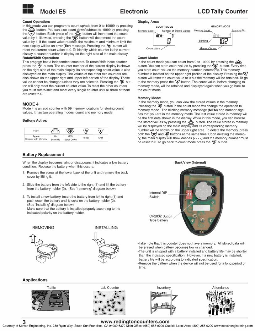
Internal DIP Switch
CR2032 Button Type Battery
TYPE
Type 4Counter with Memory
UpScroll Up
MEMScroll Down
ShiftReset
Battery Replacement
When the display becomes faint or disappears, it indicates a low battery condition. Replace the battery when this occurs.
1. Remove the screw at the lower back of the unit and remove the back cover by lifting it.
2. Slide the battery from the left side to the right (1) and lift the battery from the battery holder (2). (See “removing” diagram below)
3. To install a new battery, insert the battery from left to right (1) and push down the battery until it locks on the battery holder (2). (See “installing” diagram below) Make sure that the battery is installed properly according to the indicated polarity on the battery holder.
-Take note that this counter does not have a memory. All stored data will be erased when battery becomes low or changed.
-The unit is shipped with a battery installed and battery life may be shorter than the indicated specification. However, if a new battery is installed, battery life will be according to indicated specification.
-Remove the battery when the device will not be used for a long period of time.
REMOVING
21
INSTALLING
21
Back View (Internal)
Courtesy of Steven Engineering, Inc.-230 Ryan Way, South San Francisco, CA 94080-6370-Main Office: (650) 588-9200-Outside Local Area: (800) 258-9200-www.stevenengineering.com