model-based systems engineering - mcgill...
TRANSCRIPT

Systems Realization Laboratory
© 2008, Chris Paredis
Model-BasedSystems Engineering
Chris Paredis
Systems Realization LaboratoryProduct and Systems Lifecycle Management CenterG.W. Woodruff School of Mechanical Engineering
Georgia Institute of Technology
www.srl.gatech.edu www.pslm.gatech.edu
Systems Realization Laboratory© 2008, Chris Paredis2
Presentation Overview
Context: What is Model-Based Systems Engineering?Why MBSE?A simple model of knowledge and information in MBSEWhich kinds of knowledge and information?• Information schema• Language mappings• Abstractions and idealizations• Analysis patterns• Synthesis patterns• Design Workflow
Challenges and Summary

Systems Realization Laboratory© 2008, Chris Paredis3
A Systems Approach for Product DevelopmentTechnology Trends• Miniaturization• Embedded intelligence• Networked connectivity
Modularization• One subsystem per function• Standardized interfaces
Systems Approach• Increased number of
functions• New functions by integrating
multiple subsystems• New architectures
(source: DaimlerChrysler)

Systems Realization Laboratory© 2008, Chris Paredis4
Traditional Design Approaches
Document-centric, systematic information transformations
Generally, information is transferred manually between design steps and team members
Output is large set of documents
Inadequate for contemporary SE
Planning & Task Clarification
Conceptual Design
Embodiment Design
Detail Design

Systems Realization Laboratory© 2008, Chris Paredis5
Challenges in Systems Engineering
Multiple integrated functions
Multiple engineering disciplines
Multiple stakeholders
Globally distributed, heterogeneous design teams
Complex, emergent system behavior
Large quantities of design knowledge and information
Need Formal, Model-Based Approach

Systems Realization Laboratory© 2008, Chris Paredis6
Presentation Overview
What is Model-Based Systems Engineering?Why MBSE?A simple model of knowledge and information in MBSEWhich kinds of knowledge and information?• Information schema• Language mappings• Abstractions and idealizations• Analysis patterns• Synthesis patterns• Design Workflow
Challenges and Summary

Systems Realization Laboratory© 2008, Chris Paredis7
RR
R
Knowledge & Information in Systems Engineering
RR
RR
R
RR
DesignersSuppliers
R
RR
RR
R
RR
RR
RR
R R
R
R
R
R
ManufacturingAnalystsImplicit
Not Computer-interpretable
Not Interoperable
Coarse-grainedPDM
CAD1CAD2
FEM
ProcessPlanning
R
Systems Realization Laboratory© 2008, Chris Paredis8
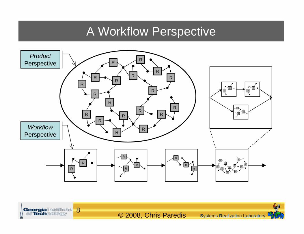
A Workflow Perspective
RR
R
RR
R R
RR
R
RR
R
RR
RR
RR
RR
RR
RR
RR
R
R
RR R
R
R
R
R
RR
RR
RR
RR
RR
R
R
RR R
R
R
R
R
RR
RR
RR
RR
RR
R
RR
R R
RR
R
RR
R
RR
RR
RR
RR
RR
RR
RR
R
R
RR R
R
R
R
R
RR
RR
RR
RR
RR
R
R
RR R
R
R
R
R
Product Perspective
Workflow Perspective
RR
RR
RR
RR
RR
R
RR
R

Systems Realization Laboratory© 2008, Chris Paredis9
Knowledge & Information in Systems Engineering
Infrastructure: Security Notification Communication VisualizationInfrastructure: Security Notification Communication Visualization
ProcessPerspective
Requirements Definition
Product Portfolio Planning
RR
RR
RR
R
RR
R
RR
RR
RR
R
RR
R
Maintenance & Support
R
R
R
R
Knowledge
Information
Knowledge
Information
ExecutionPerspective
GRIDAnalystsAnalystsDesignersDesigners
SuppliersSuppliers ManufacturingManufacturing
CAD
R
RR
R
RR
R
R
R
R
R
R
R
R
R
R
R
RR
R
R
R
R
R
RR
R
R
R
R
R
R
R
R
R
R
R
R
R
R
R
R
R
R
CADFEM
ProcessPlanning
PDM
Product Perspective
Information
Knowledge
Information
Knowledge
Information
Knowledge
Information
Knowledge
Information
Knowledge
Knowledge& InformationRepositories
WorkflowPerspective

Systems Realization Laboratory© 2008, Chris Paredis10
Information Economics
BenefitCost
Information is only valuableto the extent that it leads to better decisions
• Representation• Modeling• Computation
Better designdecisionhigher utility
Design Research: Models, Methods, Toolsfor Shifting the Balance towards Higher Value

Systems Realization Laboratory© 2008, Chris Paredis11
Presentation Overview
What is Model-Based Systems Engineering?Why MBSE?A simple model of knowledge and information in MBSEWhich kinds of knowledge and information?• Information schema• Language mappings• Abstractions and idealizations• Analysis patterns• Synthesis patterns• Design Workflow
Challenges and Summary

Systems Realization Laboratory© 2008, Chris Paredis12
Information Schema
Traditionally: tool-specific proprietary schema• CAD• Finite element modeling• Discrete event simulation• Few formal representations in SE
Standardization• e.g.: STEP (ISO 10303) – Standard for the Exchange of Product
data• Intent: Reduce the number of translators from N2 to N• Always lagging behind• Overlap and inconsistencies
Not all types of information have been modeled formally.The models are changing over time.
Islands ofKnowledge & Information

Systems Realization Laboratory© 2008, Chris Paredis13
Example of Standardization: STEP

Systems Realization Laboratory© 2008, Chris Paredis14
Federated Model (Russell Peak et al.)
One single master model is impossible / impractical• Evolution• Different levels of
abstraction
Relationships must be fine-grained• Not file-based
Domain
Abs
tract
ion
Leve
l
Req
uire
men
ts
Stru
ctur
es
Elec
troni
cs
Hum
an In
tera
ctio
n
Systems Engineering
Models of varying abstractions and domains
Legend
Model interfaces:Associativities among domain-specific models & system-level models
Dev
elop
men
t Pro
cess
…
Fine-grained models:Information objectsParametric relations
…
…
… …
…
After Bajaj, Peak, & Waterbury2003-09
Customer /Acquisitions…

Systems Realization Laboratory© 2008, Chris Paredis15
SysML as a Federated Model for MBSE
Visual information modeling for systems engineeringBased on UML 2Used to support system specification, analysis, design, verification and validation
UML2 SysML™
Systems Realization Laboratory© 2008, Chris Paredis16
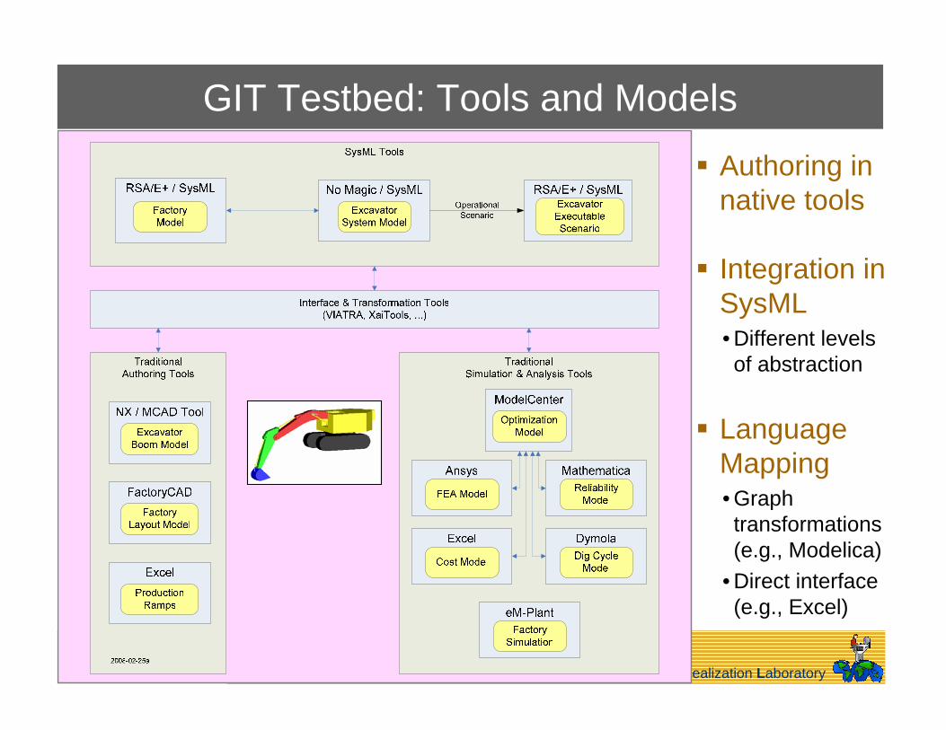
GIT Testbed: Tools and Models
Authoring innative tools
Integration in SysML• Different levels of abstraction
Language Mapping• Graph transformations (e.g., Modelica)
• Direct interface (e.g., Excel)
Systems Realization Laboratory© 2008, Chris Paredis17
Related Work: Model Integration with SysML
“…SysML is intended to unify the diverse modeling languages used by systems engineers.” (SysML Specification, 2007)Constrained Objects (Peak et al., 2001, 2005)ModelicaML (Pop et al., 2007)UMLH (Nytsch-Geusen, 2007)

Systems Realization Laboratory© 2008, Chris Paredis18
Relevant SysML Modeling Constructs
BlocksValue typesPart propertiesValue propertiesStereotypes
bdd Car Definition
WheelSuspension
Shock
valuesdampingCoef: Real
Car
valuesmass: SI.Mass = 1500
Coil
valuesspringRate: Real
«requirement»ReboundReq
text = “When disturbed by 0.1 m, the suspension shall settle to 5% of steady state in under 1 sec.”
«satisfy»
values«moe» settlingTime: Time
suspension
«valueType»SI.Mass
unit = kg
coil shock
Systems Realization Laboratory© 2008, Chris Paredis19
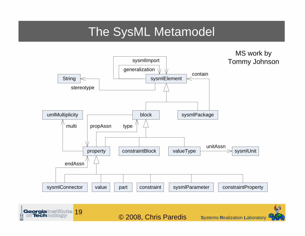
The SysML Metamodel
block
sysmlElement
sysmlPackage
valueTypeconstraintBlockproperty
umlMultiplicity
partsysmlConnector value constraint constraintPropertysysmlParameter
sysmlUnit
String
generalization
sysmlImport
stereotype
typepropAssnmulti
contain
endAssn
unitAssn
MS work byTommy Johnson

Systems Realization Laboratory© 2008, Chris Paredis20
The Modelica Metamodel
modelicaPackage
class
modelicaConnector modelicaType
modelicaUnit
equation
initialEquationconnectClause
component
arraySizemodelicaParameter
unitAssn
extendscomposition
modelicaImport
eqnAssn
size
type
componentRef

Systems Realization Laboratory© 2008, Chris Paredis21
The Correspondence Metamodel
block
sysmlPackage
valueType
property
sysmlConnector
constraint
modelicaPackage
class
modelicaConnector
modelicaType
equation
initialEquation
connectClause
component
modelicaParameter
block2class
block2modelicaConnector
valueType2modelicaType
property2component
property2modelicaParameter
constraint2equation
constraint2initialEquation
sysmlConnector2connectClause
sysmlPackage2modelicaPackage
classR
classR
classR
modelicaPackageR
componentR
componentR
equationR
equationR
connectClauseR
blockR
blockR
blockR
sysmlPackageR
propertyR
propertyR
constraintR
constraintR
sysmlConnectorR
SysML ModelicaCorrespondence

Systems Realization Laboratory© 2008, Chris Paredis22
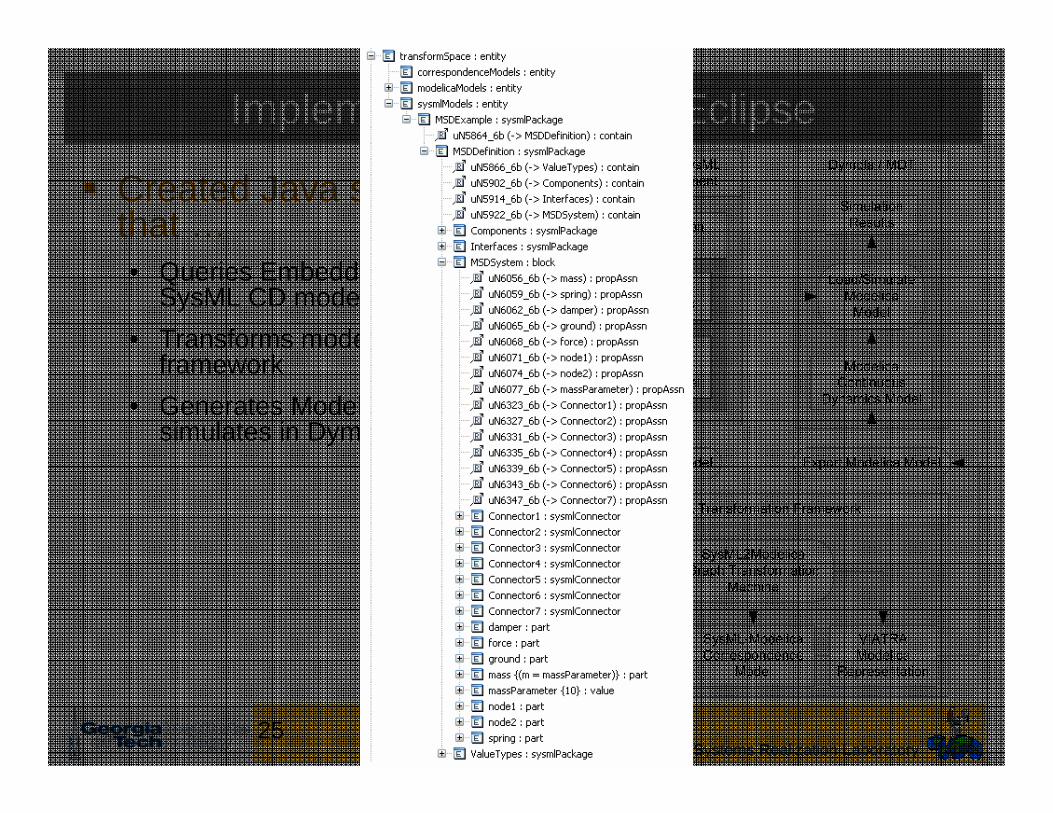
Implementation in RSD/Eclipse
Created Java software that …• Queries Embedded Plus (E+)
SysML CD model• Transforms model in
VIATRA2 framework• Generates Modelica code &
simulates in Dymola

Systems Realization Laboratory© 2008, Chris Paredis23
Implementation in RSD/Eclipse
Created Java software that …• Queries Embedded Plus (E+)
SysML CD model• Transforms model in VIATRA
framework• Generates Modelica code &
simulates in Dymola

Systems Realization Laboratory© 2008, Chris Paredis24
Implementation in RSD/Eclipse
Created Java software that …• Queries Embedded Plus (E+)
SysML CD model• Transforms model in VIATRA
framework• Generates Modelica code &
simulates in Dymola
Systems Realization Laboratory© 2008, Chris Paredis25
Implementation in RSD/Eclipse
Created Java software that …• Queries Embedded Plus (E+)
SysML CD model• Transforms model in VIATRA
framework• Generates Modelica code &
simulates in Dymola

Systems Realization Laboratory© 2008, Chris Paredis26
Implementation in RSD/Eclipse
Created Java software that …• Queries Embedded Plus (E+)
SysML CD model• Transforms model in VIATRA
framework• Generates Modelica code &
simulates in Dymola

Systems Realization Laboratory© 2008, Chris Paredis27
Implementation in RSD/Eclipse
Created Java software that …• Queries Embedded Plus (E+)
SysML CD model• Transforms model in VIATRA
framework• Generates Modelica code &
simulates in Dymola

Systems Realization Laboratory© 2008, Chris Paredis28
Implementation in RSD/Eclipse
Created Java software that …• Queries Embedded Plus (E+)
SysML CD model• Transforms model in VIATRA
framework• Generates Modelica code &
simulates in Dymola

Systems Realization Laboratory© 2008, Chris Paredis29
The Hydraulically Powered Excavator Example
Demonstrates scalability of the integration approachRepresents set of over 11,000 equationsDepicts CD of earth-moving excavatorModel includes…• hydraulic actuators & control circuitry (Fluid Power Library)• rigid-body mechanics (User-defined external model)• world reference model (Modelica Standard Library)• operator command signals (User-defined external model)

Systems Realization Laboratory© 2008, Chris Paredis30
The Hydraulically Powered Excavator Example
Demonstrates scalability of the integration approachRepresents set of over 11,000 equationsDepicts CD of earth-moving excavatorModel includes…• hydraulic actuators & control circuitry (Fluid Power Library)• rigid-body mechanics (User-defined external model)• world reference model (Modelica Standard Library)• operator command signals (User-defined external model)

Systems Realization Laboratory© 2008, Chris Paredis31
Presentation Overview
What is Model-Based Systems Engineering?Why MBSE?A simple model of knowledge and information in MBSEWhich kinds of knowledge and information?• Information schema• Language mappings• Abstractions and idealizations• Analysis patterns• Synthesis patterns
Managing Design WorkflowSummary

Systems Realization Laboratory© 2008, Chris Paredis32
Federated Model (Russell Peak et al.)
Decomposability coupling
between detailed models is limited
Abstractionhide the
details
Domain
Abs
tract
ion
Leve
l
Req
uire
men
ts
Stru
ctur
es
Elec
troni
cs
Hum
an In
tera
ctio
n
Systems Engineering
Models of varying abstractions and domains
Legend
Model interfaces:Associativities among domain-specific models & system-level models
Dev
elop
men
t Pro
cess
…
Fine-grained models:Information objectsParametric relations
…
…
… …
…
After Bajaj, Peak, & Waterbury2003-09
Customer /Acquisitions…

Systems Realization Laboratory© 2008, Chris Paredis33
Abstraction: Integrating “Black Box” Models
Represents a pre-existing model using SysML constructsHides details of the model & only exposes important aspects of modelThe «external»stereotype Modelica-specificsystem nodes &the «connectClause»stereotype
MetadataOnly important properties
“Black Box” interface
Black Box Model

Systems Realization Laboratory© 2008, Chris Paredis34
Integrating “Black Box” Models
Represents a pre-existing model using SysML constructsHides details of the model & only exposes important aspects of modelThe «external» stereotype Modelica-specific system nodes & the «connectClause» stereotype
MIA
MetadataOnly important properties
“Black Box” interface
Black Box Model
«external»MSLSlidingMass
valuesm: MSLSIMassurl: String = “…/Modelica 2.2.1/”fqn: String = “Modelica.Mechanics. Translational.SlidingMass”mime: String = “model/modelica”
partsflange_a: MSLMechanicalFlangeflange_b: MSLMechanicalFlange
«external»MSLSpring
«external»MSLDamper
«external»MSLFixed
«external»MSLMechanicalFlangeExternalMSD
mass
spring
damper
ground
bdd External MSD Definition

Systems Realization Laboratory© 2008, Chris Paredis35
Integrating “Black Box” Models
Represents a pre-existing model using SysML constructsHides details of the model & only exposes important aspects of modelThe «external» stereotype Modelica-specific system nodes & the «connectClause» stereotype
MIA
MetadataOnly important properties
“Black Box” interface
Black Box Model
par ExternalMSD
damper: MSLDamper
flange_b: MSLMechanicalFlange
mass: MSLSlidingMass
flange_a: MSLMechanicalFlange
spring: MSLSpring
flange_a: MSLMechanicalFlange
flange_b: MSLMechanicalFlange
flange_a: MSLMechanicalFlange
flange_b: MSLMechanicalFlange
ground: MSLFixed
flange_b: MSLMechanicalFlange
«connectClause»
«connectClause» «connectClause»
«connectClause»

Systems Realization Laboratory© 2008, Chris Paredis36
Presentation Overview
What is Model-Based Systems Engineering?Why MBSE?A simple model of knowledge and information in MBSEWhich kinds of knowledge and information?• Information schema• Language mappings• Abstractions and idealizations• Analysis patterns• Synthesis patterns
Managing Design WorkflowSummary

Systems Realization Laboratory© 2008, Chris Paredis37
Idealizations
Work byFenves,
Choi, et al.

Systems Realization Laboratory© 2008, Chris Paredis38
Idealizations
Different from just abstraction:• Additional knowledge is necessary• Appropriate idealization is context dependent
Most common for finite element modeling: Transform design model into corresponding analysis model• Modify geometry
Eliminate detailsImpose symmetryDetermine dimensionality
• Define materials model• Model loading conditions• Generate mesh

Systems Realization Laboratory© 2008, Chris Paredis39
Methods for Generating Finite Element Models
Direct FEA model creation• Import design from CAD tool• Modify geometry (as per idealizations)• Select elements to mesh (as per idealizations)• Mesh
Script-based FEA model structure creation• Author a solver-specific script
Idealized geometry, material properties, load, boundary(and/or initial conditions)Element, mesh size, …
• Run script for different instances

Systems Realization Laboratory© 2008, Chris Paredis40
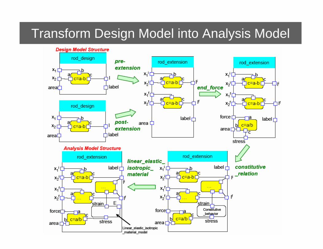
Methods for Generating Finite Element ModelsMulti-representation architecture-based method• 4 stepping-stone model structures• Models related by parametric constraints (per idealization) static• Analysis model = assembly of reusable building blocks• Solution-approach and method specific analysis models
(Peak, Fulton 1998)
Systems Realization Laboratory© 2008, Chris Paredis41
Transform Design Model into Analysis Model
Systems Realization Laboratory© 2008, Chris Paredis42
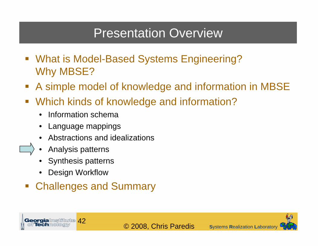
Presentation Overview
What is Model-Based Systems Engineering?Why MBSE?A simple model of knowledge and information in MBSEWhich kinds of knowledge and information?• Information schema• Language mappings• Abstractions and idealizations• Analysis patterns• Synthesis patterns• Design Workflow
Challenges and Summary
Systems Realization Laboratory© 2008, Chris Paredis43
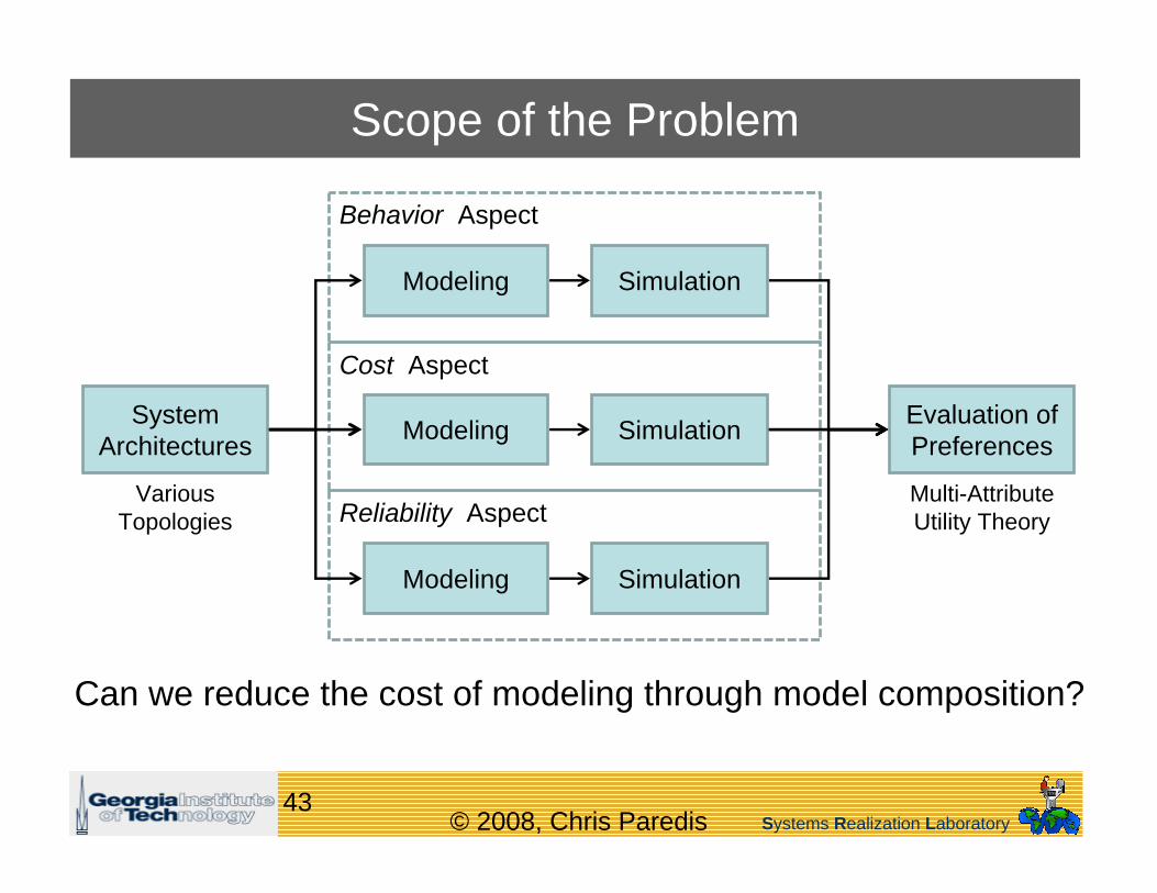
Scope of the Problem
Cost Aspect
Behavior Aspect
VariousTopologies
Multi-Attribute Utility TheoryReliability Aspect
Evaluation of Preferences
System Architectures
Modeling
Modeling
Modeling
Simulation
Simulation
Simulation
Can we reduce the cost of modeling through model composition?
Systems Realization Laboratory© 2008, Chris Paredis44
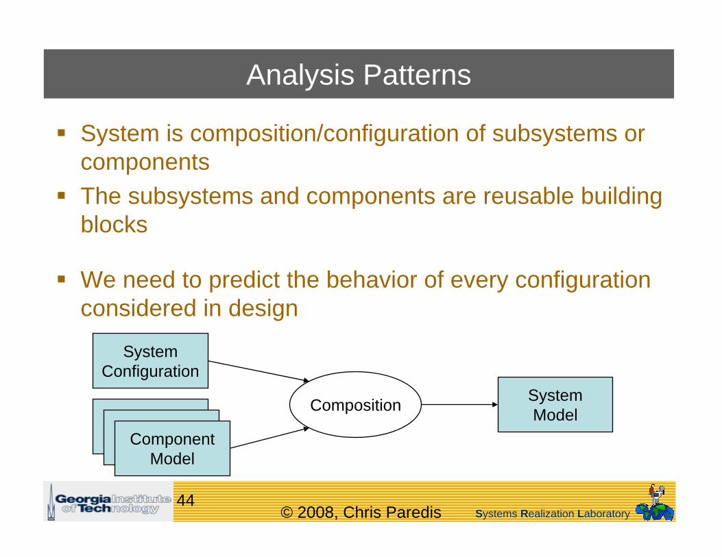
Analysis Patterns
System is composition/configuration of subsystems or componentsThe subsystems and components are reusable building blocks
We need to predict the behavior of every configuration considered in design
Composition System Model
System Configuration
ComponentModelComponent
ModelComponentModel

Systems Realization Laboratory© 2008, Chris Paredis45
Composition of Behavior Model
SysML Internal Block Diagram
System Architecture
Corresponding Algebraic ModelslidingMass.vel = vmax;slidingMass.vel = cylinder.piston.vel;cylinder.portA.q = cylinder.piston.vel*cylinder.area;cylinder.portA.q = pump.portP.q;pump.shaft.omega*pump.displ / (2*pi) = pump.portP.q;motor.shaft.omega = pump.shaft.omega;
Corresponding System-level Dynamic Model

Systems Realization Laboratory© 2008, Chris Paredis46
Multi-Aspect Component Models
MAsCoMs• Define relationships
between all the models related to a particular component or subsystem
• Model context
Aspects• Discipline• Lifecycle phase• Discretization
TimeSpace
• Math Formalism• Representation Syntax
Relief Check ConstDispl.
VarDispl.
FPcomponent
PumpValve
Hydraulic
Thermal
Algebraic
DA
E
Behavior
Formalism
Discipline
Model
Model
Model
Model
Model
Model
Model
Taxonomy of Aspects
Taxonomy ofComponents
Multi-Aspect Component Model
…
…
…
Systems Realization Laboratory© 2008, Chris Paredis47
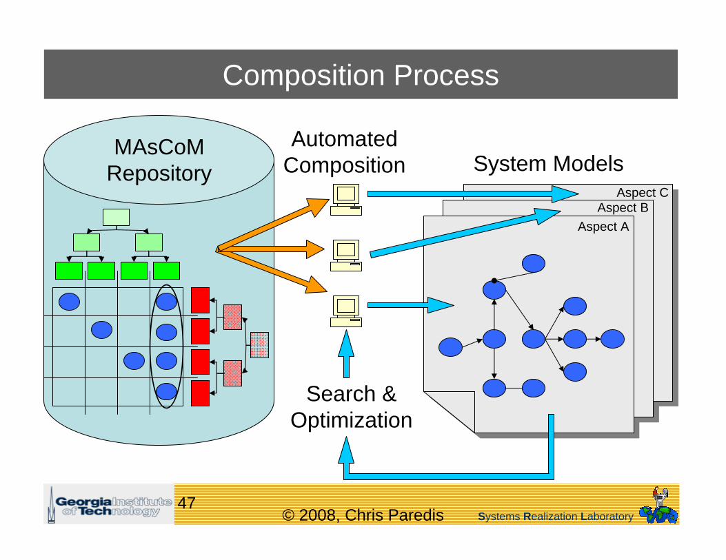
Composition Process
System ModelsMAsCoM
Repository
Search &Optimization
Aspect A
Aspect CAspect B
AutomatedComposition

Systems Realization Laboratory© 2008, Chris Paredis48
Multi-Aspect Component Models in SysML
Characterization of analysis modelof a component
Composition ofreliability models

Systems Realization Laboratory© 2008, Chris Paredis49
Presentation Overview
What is Model-Based Systems Engineering?Why MBSE?A simple model of knowledge and information in MBSEWhich kinds of knowledge and information?• Information schema• Language mappings• Abstractions and idealizations• Analysis patterns• Synthesis patterns• Design Workflow
Challenges and Summary
Systems Realization Laboratory© 2008, Chris Paredis50
Flow
Press.
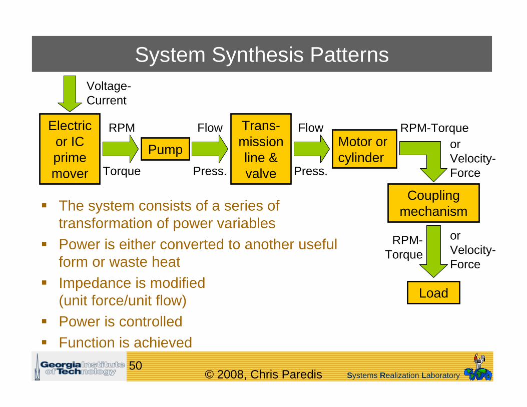
System Synthesis Patterns
The system consists of a series of transformation of power variablesPower is either converted to another useful form or waste heatImpedance is modified(unit force/unit flow)Power is controlledFunction is achieved
Electric or IC prime mover
Pump
Trans-mission line & valve
Motor or cylinder
Coupling mechanism
Load
RPM
Torque
Flow
Press.
RPM-Torque
RPM-Torque
Voltage-Current
orVelocity-Force
orVelocity-Force

Systems Realization Laboratory© 2008, Chris Paredis51
Different Architectures
Key issues:• Hardware + Controllers• Compatibility constraints• Hidden dependencies• Best solution depends on the
preferences of the designer• Each concept is a large set of
design alternatives

Systems Realization Laboratory© 2008, Chris Paredis52
Graph Grammars
Capture application domain knowledge in a formal grammarGrammar describes plausible configurations• Ideally optimal configurations• Even feasible configurations may too complex to define in grammar
Explore design space by applying transformation rules in some randomized fashion
Which knowledge to model in terms of transformations?Which knowledge to model in terms of analyses?
Systems Realization Laboratory© 2008, Chris Paredis53
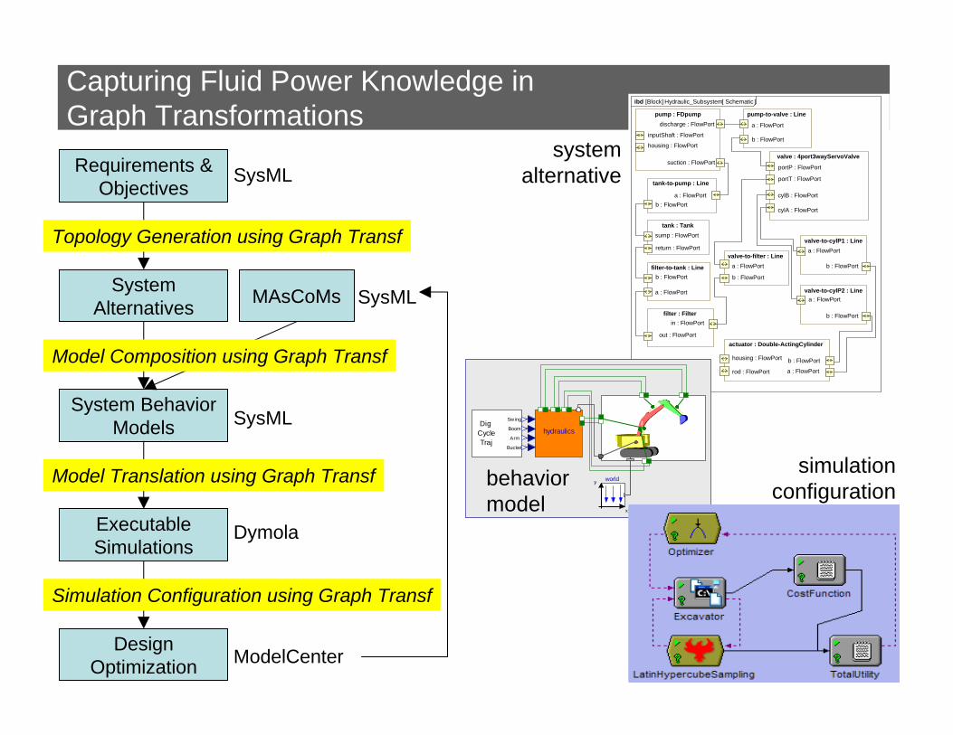
Capturing Fluid Power Knowledge inGraph TransformationsRequirements &
ObjectivesSysML
Executable Simulations
Dymola
System Behavior Models SysML
Topology Generation using Graph Transf
Model Composition using Graph Transf
Model Translation using Graph Transf
Design Optimization ModelCenter
System Alternatives MAsCoMs SysML
Simulation Configuration using Graph Transf
Hydraulic_Subsystem Schematic[Block] ibd [ ]
actuator : Double-ActingCylinder
a : FlowPort
b : FlowPorthousing : FlowPort
rod : FlowPort
valve : 4port3wayServoValve
cylA : FlowPort
cylB : FlowPort
portP : FlowPort
portT : FlowPort
pump : FDpumpdischarge : FlowPort
suction : FlowPort
housing : FlowPort
inputShaft : FlowPort
tank-to-pump : Line
a : FlowPortb : FlowPort
pump-to-valve : Line
a : FlowPort
b : FlowPort
valve-to-cylP1 : Linea : FlowPort
b : FlowPort
valve-to-cylP2 : Linea : FlowPort
b : FlowPortfilter : Filterin : FlowPort
out : FlowPort
valve-to-filter : Linea : FlowPort
b : FlowPortfilter-to-tank : Line
a : FlowPort
b : FlowPort
tank : Tank
return : FlowPort
sump : FlowPort
hydraulics
world
x
y
Dig Cycle
Arm
Boom
Sw ing
BucketTraj
systemalternative
behaviormodel
simulationconfiguration

Systems Realization Laboratory© 2008, Chris Paredis54
Design Workflow
Ideally all models would always be consistent
In practice, changes need to be propagated carefully• e.g., large parametric assembly model, ECAD-MCAD integration• Traceability is crucial, but automated propagation is not desirable
Propagation is controlled at decision points• Human decision-maker needs to remain in the loop• But in the end, all models should be consistent
How does one model the application of transformations?

Systems Realization Laboratory© 2008, Chris Paredis55
Challenges and Summary
Evolving representationsmaintenance of transformations, schema, instances
Maintaining multiple views – bi-directionalModeling idealizations as graph transformationsCapturing knowledge context of synthesis rulesHidden dependencies
system-level interfaces are only modelsWorkflow and consistency management
Systems Realization Laboratory© 2008, Chris Paredis56
Acknowledgments
Graduate Students• Manas Bajaj• Jonathan Jobe• Tommy Johnson• Aleks Kerzhner• Richard Malak• Roxanne Moore• Stephanie Thompson• Lina Tucker
Collaborators• Roger Burkhart (Deere)• Sandy Friedenthal (LMCO)• Leon McGinnis (GT)• Russell Peak (GT)
Sponsors:• National Science Foundation
Grant DMI-0522116• National Science Foundation,
Center for Complex and Efficient Fluid Power
• Deere & Co.• Lockheed Martin
Questions?