model-based systems and software engineering · · 2016-02-06practice systems development is...
TRANSCRIPT
Copyright © 2012 Madni-Alvidrez
Model-Based Systems and Software
Engineering
Dr. Mark L. McKelvin
Lecturer, USC Viterbi SAE Program
Copyright © 2012 Madni-Alvidrez
About Me…
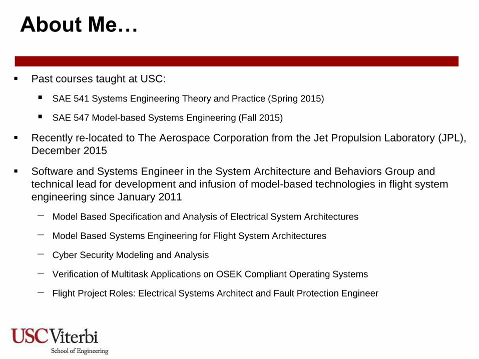
Past courses taught at USC:
SAE 541 Systems Engineering Theory and Practice (Spring 2015)
SAE 547 Model-based Systems Engineering (Fall 2015)
Recently re-located to The Aerospace Corporation from the Jet Propulsion Laboratory (JPL),
December 2015
Software and Systems Engineer in the System Architecture and Behaviors Group and
technical lead for development and infusion of model-based technologies in flight system
engineering since January 2011
− Model Based Specification and Analysis of Electrical System Architectures
− Model Based Systems Engineering for Flight System Architectures
− Cyber Security Modeling and Analysis
− Verification of Multitask Applications on OSEK Compliant Operating Systems
− Flight Project Roles: Electrical Systems Architect and Fault Protection Engineer

Copyright © 2012 Madni-Alvidrez
About Me… (continued)
Graduated from University of California, Berkeley in Electrical Engineering and Computer
Sciences
Major emphasis was Design, Modeling, and Analysis (formerly CAD/EDA for electronic based
systems), supervised by Alberto Sangionvanni-Vincentelli
Minor emphasis on Programming Systems and Management of Technology
Dissertation work was on fault tolerant architectures for automotive systems
Other industrial experience include:
General Motors Research and Development (Palo Alto), Intel Corporation (Santa Clara/Hillsboro), HRL
Laboratories (Malibu), Sandia National Labs (Livermore), Army Research Laboratory (Aberdeen
Proving Ground), Army High Performance Research Center (Minneapolis)

Copyright © 2012 Madni-Alvidrez
Outline
Introduction to Systems Engineering
Processes, Methods, and Tools
Model-Based Systems and Software Engineering
Applications of Model-Based Systems and Software Engineering
Enabling Model-Based Systems Engineering with SysML
In-Class Exercise: Using the SysML Profile in MagicDraw
Quiz (5-10 mins)

Copyright © 2012 Madni-Alvidrez
What is a System?
DOD: An integrated composite of people, products, and processes that provide a
capability to satisfy a stated need or objective.
NASA: A set of interrelated components which interact with one another in an organized
fashion toward a common purpose.
INCOSE: A combination of interacting elements organized to achieve one or more stated
purposes.
Simply stated, a system is an integrated composite of people, products, and processes
that provides a capability to satisfy a stated need or objectives.
Copyright © 2012 Madni-Alvidrez
What is Systems Engineering?
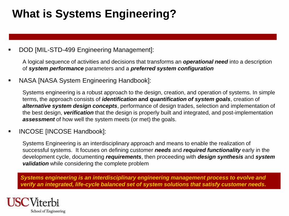
DOD [MIL-STD-499 Engineering Management]:
A logical sequence of activities and decisions that transforms an operational need into a description
of system performance parameters and a preferred system configuration
NASA [NASA System Engineering Handbook]:
Systems engineering is a robust approach to the design, creation, and operation of systems. In simple
terms, the approach consists of identification and quantification of system goals, creation of
alternative system design concepts, performance of design trades, selection and implementation of
the best design, verification that the design is properly built and integrated, and post-implementation
assessment of how well the system meets (or met) the goals.
INCOSE [INCOSE Handbook]:
Systems Engineering is an interdisciplinary approach and means to enable the realization of
successful systems. It focuses on defining customer needs and required functionality early in the
development cycle, documenting requirements, then proceeding with design synthesis and system
validation while considering the complete problem
Systems engineering is an interdisciplinary engineering management process to evolve and
verify an integrated, life-cycle balanced set of system solutions that satisfy customer needs.

Copyright © 2012 Madni-Alvidrez
System Engineering Activities
Requirements
Analysis
Functional Analysis
and Allocation
Design Synthesis
Systems Analysis
and Control
Inputs Outputs
Design Loop
Requirements Loop
Verification Loop
Systems engineering is accomplished through a process that considers an iterative
application of these major activities across the system lifecycle with the goal of
providing a quality product that meets user needs.

Copyright © 2012 Madni-Alvidrez
System Engineering Activities
Requirements
Analysis
Functional Analysis
and Allocation
Design Synthesis
Systems Analysis
and Control
Inputs Outputs
Design Loop
Requirements Loop
Verification Loop
Many artifacts are used and captured throughout the process to support these
major activities.
• System use case/scenarios
• Needs analysis
• Requirements decomposition
• Logical decompositions
• Functional scenarios
• Logical subsystems
• HW/SW partitioning
• Deployment/Physical
architecture
• Trade study
• Requirements
decomposition/hierarchy
• Test cases/procedures
• System architecture
• Baseline/specifications

Copyright © 2012 Madni-Alvidrez
Iteration of System Engineering Activities
Across Lifecycle

Copyright © 2012 Madni-Alvidrez
Outline
Introduction to Systems Engineering
Processes, Methods, and Tools
Model-Based Systems and Software Engineering
Applications of Model-Based Systems and Software Engineering
Enabling Model-Based Systems Engineering with SysML
In-Class Exercise: Using the SysML Profile in MagicDraw
Quiz (5-10 mins)

Copyright © 2012 Madni-Alvidrez
Process, Methods, and Tools
A process is a sequence of
activities that achieve a
stated objective. It defines
“what” is done, not “how” it
is accomplished (hence,
tool agnostic).

Copyright © 2012 Madni-Alvidrez
Process, Methods, and Tools
A method is a technique that
is used to define “how” a
task is accomplished. It
guides the process using
selected tools.

Copyright © 2012 Madni-Alvidrez
Process, Methods, and Tools
A tool is an instrument that
assists in accomplishing a task.

Copyright © 2012 Madni-Alvidrez
Process, Methods, and Tools
A methodology is a collection
of related methods, processes,
and tools (i.e. a “cookbook”).

Copyright © 2012 Madni-Alvidrez
Process, Methods, and Tools
A methodology is a collection
of related methods, processes,
and tools (i.e. a “cookbook”).
The capabilities of the technology
and skills of people are part of the
environment which enables or
constrains the process, methods,
and tools.

Copyright © 2012 Madni-Alvidrez
Outline
Introduction to Systems Engineering
Processes, Methods, and Tools
Model-Based Systems and Software Engineering
Applications of Model-Based Systems and Software Engineering
Enabling Model-Based Systems Engineering with SysML
In-Class Exercise: Using the SysML Profile in MagicDraw
Quiz (5-10 mins)

Copyright © 2012 Madni-Alvidrez
Modern System Trends
Increasing complexity due to knowledge expansion and technology (i.e.
Moore’s Law, Metcalf’s Law)
Increased complexity of products and processes
Product competition and time-to-market pressures
Increase customer demand on more functionality

Copyright © 2012 Madni-Alvidrez
Example: Specification and Design of Space
System Interfaces
Mars Exploration Rover
(MER)
Mars Pathfinder Mars Science Laboratory
(MSL)
MSL 2020
• 850 interface signals
• 4 instruments
• 1750 interface signals
• 9 instruments
• 2350 interface signals
• 10 instruments
• ~2400 interface signals
• 8-10 instruments
Increasing complexity in interface management as demand for more functionality increases
Europa
• ~3000 interface signals
SMAP
• 1000 interface signals
• 2 instruments
Cassini
• 2500 interface signals
• 15 instruments
Functional decomposition and allocation to physical components drive interface requirements and subsequent wiring and cabling design.

Copyright © 2012 Madni-Alvidrez
Challenges in Traditional Systems Engineering
Practice
Systems development is driven by loosely-coupled documents (document-
centric)
Transforming mission requirements to implementation is ad-hoc
Managing engineering design information and design changes across
domains
Increasing risk of not meeting cost and schedule constraints

Copyright © 2012 Madni-Alvidrez
Model-Based Approach
System engineering practice for capturing system architecture is shifting from document-centric
to model-centric approaches. This trend is Model-Based Systems Engineering (MBSE), where
an integrated set of multi-view models span stages in the system lifecycle at different levels of
abstraction.

Copyright © 2012 Madni-Alvidrez
What is “Model-Based”?
A model is an abstract representation of reality
o Informal vs. formal (i.e. “strawman figure”, textual)
o Descriptive vs. predictive
o Physical (i.e. prototype) vs. abstract
All engineering disciplines rely on abstraction, and therefore models; in model-based
engineering, models play a central role
Types of models include,
o Physical models: A scale model of relevant physical properties of a real system
o Graphical models: Visual diagrams to describe high-level structure and behaviors of a system
o Analytical models: A set of mathematical or logical expressions to express the relationships
among entities in the system
An effective use of models is in automated testing and verification. However, models have many
other purposes as well, such as, communication, requirements development and analysis.

Copyright © 2012 Madni-Alvidrez
Models in Software Engineering
A model provides an abstract and analyzable description of software artifacts, created
for a purpose
Abstract
Details are omitted
Partial representation
Smaller and simpler than the artifact being modeled
Analyzable
Leads to task automation (i.e. static code analysis, formal verification, code generation)
Requirements models Architecture models Behavior models Test cases

Copyright © 2012 Madni-Alvidrez
Model-Based Systems and Software Engineering
System
Engineering Models of
Systems
Model-Based Systems
Engineering
Software
Engineering Models of
Software Model-Based Software
Engineering

Copyright © 2012 Madni-Alvidrez
How Can Models Help in Model-Based Systems
and Software Engineering?
Improve communications amongst
teams
Shared understanding of the system
Facilitate risk identification
Improve management of system
complexity
Traceability
Multiple views
Multiple levels of abstraction
Incremental development
Model integration, synchronization
and consistency
Improve design quality
Reduce errors that occur late in
system development
Early and on-going verification and
validation
Systematic design space exploration
Improve knowledge capture and
reuse
Added value throughout lifecycle
(i.e. training)
Use models from previous missions
as reference architectures or
starting point for new missions

Copyright © 2012 Madni-Alvidrez
Outline
Introduction to Systems Engineering
Processes, Methods, and Tools
Model-Based Systems and Software Engineering
Applications of Model-Based Systems and Software Engineering
Enabling Model-Based Systems Engineering with SysML
In-Class Exercise: Using the SysML Profile in MagicDraw
Quiz (5-10 mins)
Copyright © 2012 Madni-Alvidrez
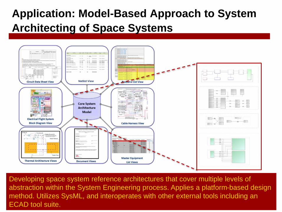
Application: Model-Based Approach to System
Architecting of Space Systems
Developing space system reference architectures that cover multiple levels of
abstraction within the System Engineering process. Applies a platform-based design
method. Utilizes SysML, and interoperates with other external tools including an
ECAD tool suite.

Copyright © 2012 Madni-Alvidrez
Application: Formal Verification of Spacecraft
Fault Behaviors
Validate the Fault Protection System algorithms for SMAP by
creating a model in SysML that can be formally verified.
Copyright © 2012 Madni-Alvidrez
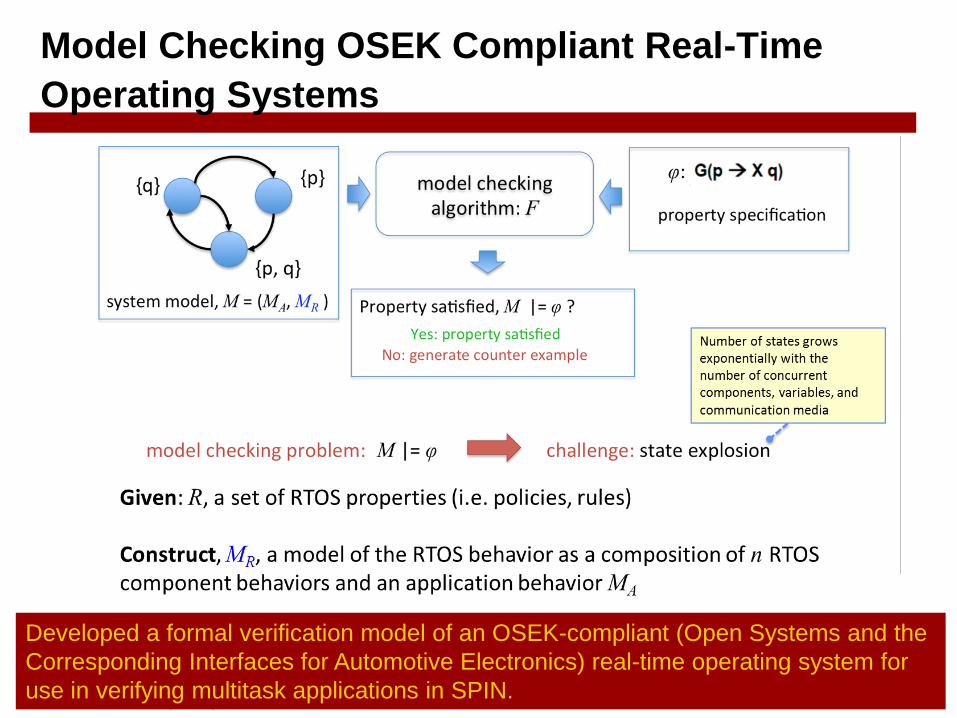
Model Checking OSEK Compliant Real-Time
Operating Systems
Developed a formal verification model of an OSEK-compliant (Open Systems and the
Corresponding Interfaces for Automotive Electronics) real-time operating system for
use in verifying multitask applications in SPIN.

Simulating Power Distribution, Thermal Control, and Fault Protection with Heterogeneous Execution Semantics
In our model
• Continuous Time
• Finite State Machines
Examples of Other domains
• Discrete Event
• Dataflow
• Process Networks

Testing with Simulated Fault Injection
Model of fault injection into sensor

Simulation Results Power Subsystem

Simulation Results Thermal Control Subsystem
Without fault handling
With fault handling
Copyright © 2012 Madni-Alvidrez
Outline
Introduction to Systems Engineering
Processes, Methods, and Tools
Model-Based Systems and Software Engineering
Applications of Model-Based Systems and Software Engineering
Enabling Model-Based Systems Engineering with SysML
In-Class Exercise: Using the SysML Profile in MagicDraw
Quiz (5-10 mins)

Copyright © 2012 Madni-Alvidrez
Modeling Languages
Image s
ourc
e: L
ickly
, Shelto
n, L
atro
nic
o, L
ee
Language = syntax (notations, associations) + semantics (meaning of notations and associations)
Different types of models are expressed in various languages.

Copyright © 2012 Madni-Alvidrez
SysML

Copyright © 2012 Madni-Alvidrez
SysML and Tools
SysML (systems modeling language) is a specification for a visual language that is used
to represent system models and support system engineering activities
Specification maintained by the Objects Management Group (OMG) (URL:
http://www.sysml.org)
Specification for SysML is open-source
It comprises a collection of symbols (notation) and static semantics
SysML is a descriptive language
Can be used for simulation (with appropriate simulation engines and software tools)
Commonly used tools that implement SysML:
− Modelio (open source)
− Papyrus (open source)
− MagicDraw (NoMagic Inc.)
− IBM Rational Rapsody (IBM)
− Enterprise Architect (Sparx Systems)
Modelio
Enterprise Architect

Copyright © 2012 Madni-Alvidrez
Four Pillars of SysML
Requirements: requirement hierarchies,
traceability
Parametrics: quantitative attributes and
relationships
Sourc
e: O
bje
ct M
anagem
ent G
roup
Structure: system hierarchies, interconnections
Behavior: state based, functional behaviors

Copyright © 2012 Madni-Alvidrez
SysML Diagram Taxonomy
38

Copyright © 2012 Madni-Alvidrez
Structure: Packages
• Concept is similar to folders/subdirectories that organize
files on computers
• Models are organized in any way that makes sense to
model builders and users – no single “right” way
• A caution though: think very carefully about organization,
although changes will occur and can be done, the larger
a model becomes, the more difficult it is to change
• Example organizations:
− By system structure (hierarchy)
− By domain (requirements, behaviors…)
− By viewpoints (areas of interest)
39

Copyright © 2012 Madni-Alvidrez
Model Organization Examples
40

Copyright © 2012 Madni-Alvidrez
Blocks
• Blocks are primary structural elements
• Based on UML “class”
• May be used to describe
− Concepts
− Requirements
− Systems
− Subsystems
− Components
− Software
− People
− Facilities
− Data
− …
41

Copyright © 2012 Madni-Alvidrez
Blocks
• Comprise multiple compartments
− Properties
oPart property: usage of block in an enclosing block
oReference property: a part not owned by the enclosing block,
e.g. an interface between 2 parts
oValue property: defines a value and units, dimensions…
− Operations
− Constraints
− Allocations to the block
− Requirements on the block
42
Copyright © 2012 Madni-Alvidrez
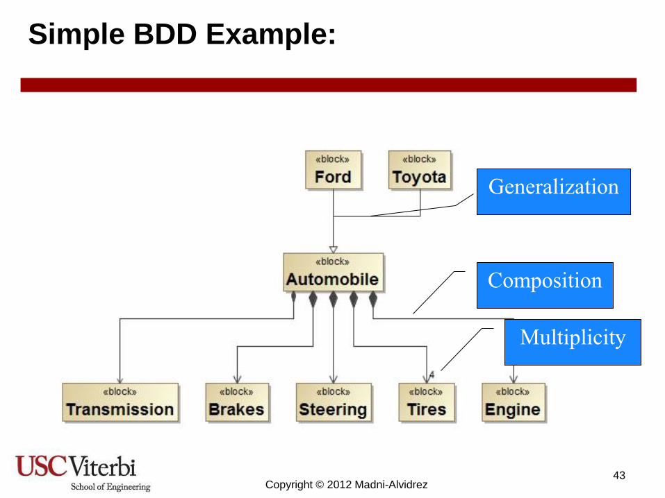
Simple BDD Example:
Composition
Generalization
Multiplicity
43
Copyright © 2012 Madni-Alvidrez
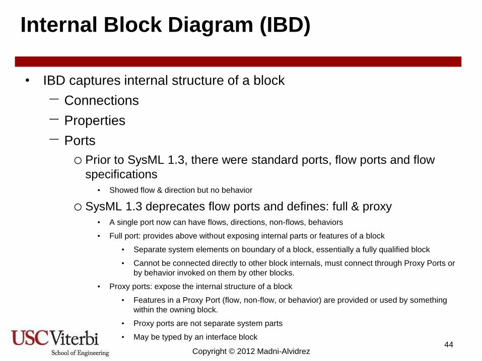
Internal Block Diagram (IBD)
• IBD captures internal structure of a block
− Connections
− Properties
− Ports
o Prior to SysML 1.3, there were standard ports, flow ports and flow
specifications
• Showed flow & direction but no behavior
o SysML 1.3 deprecates flow ports and defines: full & proxy
• A single port now can have flows, directions, non-flows, behaviors
• Full port: provides above without exposing internal parts or features of a block
• Separate system elements on boundary of a block, essentially a fully qualified block
• Cannot be connected directly to other block internals, must connect through Proxy Ports or
by behavior invoked on them by other blocks.
• Proxy ports: expose the internal structure of a block
• Features in a Proxy Port (flow, non-flow, or behavior) are provided or used by something
within the owning block.
• Proxy ports are not separate system parts
• May be typed by an interface block 44

Copyright © 2012 Madni-Alvidrez
IBD Example
45

Copyright © 2012 Madni-Alvidrez
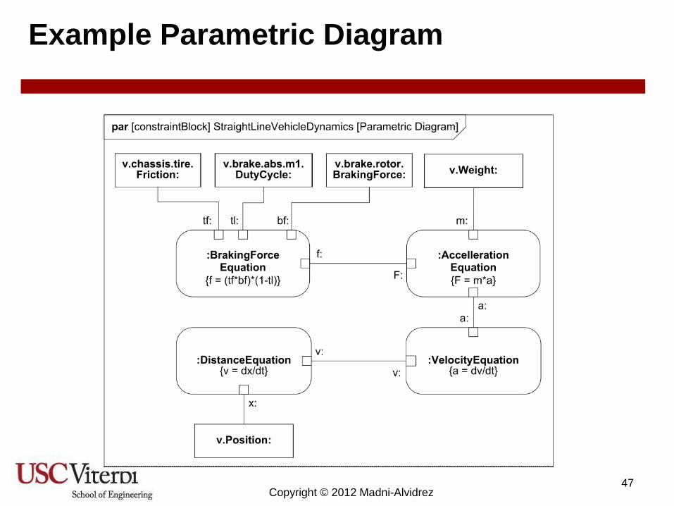
Parametric Diagrams
• Models constraints (equations) between value properties
− Supports engineering/physics analysis
− Some tools link to external math tools such as Simulink and
Matlab
− Some tools provide internal analysis capabilities
• Constraint blocks capture equations, may be expressed
formally or informally
• Parametric diagram links constraints to form an analysis
− Binds constraint to values in blocks
46
Copyright © 2012 Madni-Alvidrez
Example Parametric Diagram
47

Copyright © 2012 Madni-Alvidrez
Requirement Relationships
• Derived: a requirement is derived from another
requirement
• Satisfy: an entity (block, behavior) satisfies a requirement
• Verify: a test case verifies a requirement
• Refine: an entity refines, clarifies, explains a requirement
• Trace: a requirement is loosely related to something else
in the model
• Copy: a requirement is copied from an another
requirement
− Requirement text of child is identical to parent
48

Copyright © 2012 Madni-Alvidrez
Example Requirements Diagram
49
Arrows are opposite
of typical
requirements flow
down

Copyright © 2012 Madni-Alvidrez
Example Use Case Diagram
50

Copyright © 2012 Madni-Alvidrez
Activity Diagram
• Just a fancy flowchart –
• Specifies flows of inputs, outputs, and controls
• May include parallel, serial, repeated, conditional,
interruptible… regions
• May include “swim lanes” that show allocation of
behaviors to system resources
• An activity starts when control and/or data have arrived
− Control may start or stop an activity
• Continuous activities (rates, continuous, discrete)
• Probability (decisions with probability)
51

Copyright © 2012 Madni-Alvidrez
Example Activity Diagram
Control Flow
Object Flow
Start
Activity Final
Node
52

Copyright © 2012 Madni-Alvidrez
Another Example
53
Source: Pascal
Roques, MoDELS’11
Tutorial, October 16th,
2011

Copyright © 2012 Madni-Alvidrez
Sequence Diagram
• Models message-based behavior
− Flow of control
− Interactions
− Operations
− Loose semantics for timing/synchronization
• May be used for complicated scenarios
− Swim lanes allocate behaviors
− Hierarchical behaviors (references)
− Control logic (parallel sequences, alternates)
54

Copyright © 2012 Madni-Alvidrez
Example Sequence Diagram
55
Ref: a sequence
defined
elsewhere
Loop while
condition is
“true”
Conditional
sequences
Message, also
implies
functions
performed by
associated
actor or block

Copyright © 2012 Madni-Alvidrez
State Machine Diagrams
• Represents behavior as a state of history
− Comprises states and state transitions
− Generally support asynchronous, event-driven behavior
• Activities may be invoked during transitions, on entry,
during and exit of a state
• Guard conditions act as tests of conditions
• Can send/receive signals to communicate with blocks
during transitions
• Composition states have nested states
− May be sequential or concurrent
56

Copyright © 2012 Madni-Alvidrez
Example State Diagram
57
State
Transition
Behavior
inside
state
Behavior on
exit
Start

Copyright © 2012 Madni-Alvidrez
A Mapping of SysML Diagrams with an
MBSE Process
58

Copyright © 2012 Madni-Alvidrez
Outline
Introduction to Systems Engineering
Processes, Methods, and Tools
Model-Based Systems and Software Engineering
Applications of Model-Based Systems and Software Engineering
Enabling Model-Based Systems Engineering with SysML
In-Class Exercise: Using the SysML Profile in MagicDraw
Quiz (5-10 mins)

Copyright © 2012 Madni-Alvidrez
In-Class Exercise:
Using the SysML Profile in MagicDraw
Goal is to show how MagicDraw is
used to create models, examples
illustrate usage of tool and not
necessarily good designs!
Preparation:
1. Download and install the demo version of MagicDraw 18.3 beta
o If you have MagicDraw 18.1 or greater, then it should be sufficient for this in-
class exercise (older versions greater than 17.0.5 may have some differences
in tool usage, but the exercise will be general enough to be used with older
versions of MagicDraw)
o Note that you will need to download both MagicDraw and the SysML profile
separately
Copyright © 2012 Madni-Alvidrez
Problem Statement
You are a system engineer for a mission that is tasked to design a
spacecraft that uses a new instrument to observe the Earth. The
spacecraft must send data back to Earth through a space
communication network to the ground system. The ground operator
controls the spacecraft. Your scope is only for the spacecraft. The
spacecraft shall receive ground commands to control the instrument
and send the data back to the ground system operator. Assume the
spacecraft has three subsystems, the spacecraft computer, the
instrument, and a telecommunications subsystem. The spacecraft
shall weigh no more than 100kg.

Copyright © 2012 Madni-Alvidrez
Outline
Introduction to Systems Engineering
Processes, Methods, and Tools
Model-Based Systems and Software Engineering
Applications of Model-Based Systems and Software Engineering
Enabling Model-Based Systems Engineering with SysML
In-Class Exercise: Using the SysML Profile in MagicDraw
Quiz (5-10 mins)

Copyright © 2012 Madni-Alvidrez
Quiz (5-10 minutes)
1. List 5 examples of engineered systems that requires systems engineering. Your
examples should consider systems that are software intensive but tightly integrates
with hardware and physical processes (i.e. thermodynamics, mechanical dynamics)
2. Name three kinds of issues that models attempt to address in system and/or software
engineering.
3. True or False. Model based systems engineering is a process for systems engineering.
4. You are asked to create a model of a verification process. The verification process is a
series of tasks with clearly defined inputs and outputs. Which one of the 9 SysML
diagrams do you think is most appropriate to complete the task? Why?
5. You are a fault protection engineer. A system requirement states that there must be a
system mode that turns off the power to an instrument when a fault event occurs. If
there is no indication of a fault event, then the instrument remains in a nominal
operating state. Assuming you know nothing about the implementation (i.e. the
technology it uses, hardware, software) of the instrument, what kind of model or
SysML diagram would you use to capture this behavior?

Copyright © 2012 Madni-Alvidrez
Quiz (5-10 minutes): Answers

Copyright © 2012 Madni-Alvidrez
Quiz (5-10 minutes)
1. List 5 examples of engineered systems that requires systems
engineering. Your examples should consider systems that are
software intensive but tightly integrates with hardware and physical
processes (i.e. thermodynamics, mechanical dynamics)
Commercial airliner
Automobile
Electric Power Grid (“Smart grid”)
Space observatory/satellite
Autonomous unmanned aerial vehicle

Copyright © 2012 Madni-Alvidrez
Quiz (5-10 minutes)
1. Name three kinds of issues that models attempt to address in system and/or
software engineering.
Knowledge reuse
Consistency in design information
Traceability of requirements to design
Improved automation
Computer-aided analyses
2. True or False. Model based systems engineering is a process for systems
engineering.
False. MBSE is a method for using models as central artifacts to a systems
engineering process.

Copyright © 2012 Madni-Alvidrez
Quiz (5-10 minutes)
1. You are asked to create a model of a verification process. The verification
process is a series of tasks with clearly defined inputs and outputs. Which
one of the 9 SysML diagrams do you think is most appropriate to complete
the task? Why?
Activity diagram. An activity diagram expresses the sequential flow of activities, or
tasks, that must be accomplished. Other behavior diagrams, such as the state
machine diagram might also be applicable, but state machines tend to be more
effective in situations where knowing the state of a system element should be
emphasized.
Copyright © 2012 Madni-Alvidrez
Quiz (5-10 minutes)
1. You are a fault protection engineer. A system requirement states that there
must be a system mode that turns off the power to an instrument when a fault
event occurs. If there is no indication of a fault event, then the instrument
remains in a nominal operating state. Assuming you know nothing about the
implementation (i.e. the technology it uses, hardware, software) of the
instrument, what kind of model or SysML diagram would you use to capture
this behavior?
State machine. A state machine is an effective use of illustrating state based
behavior. Since modes tend to be triggered by asynchronous events, a state
machine makes a good choice for capturing mode transition behavior.

Copyright © 2012 Madni-Alvidrez
Backup
Copyright © 2012 Madni-Alvidrez
Fundamental Elements of System Architecture
System structure, behavior, and views are the fundamental
elements of system architecture.

Copyright © 2012 Madni-Alvidrez
What is System Architecture?
It is the fundamental and unifying system structure defined in terms of
system elements, interfaces, processes, constraints, and behaviors.
[INCOSE]
It is the structure of components, their relationships, and the principles
and guidelines governing their design and evolution over time. [DoD]
A system architecture is the link between needs analysis, project
scoping and functional analysis and the first descriptions of the system
structure.

Copyright © 2012 Madni-Alvidrez
System Architecting
System architecting is a system engineering function that helps to facilitate
understanding of the system and guides the system engineering process
o Translates mission needs and objectives into a technical solution
o Constrains the design space
o Enable trade-studies of alternatives
o Support “make-buy” decisions
Artifacts A system architecture is a
collection of artifacts that
communicate system
characteristics such as behavior,
structure and qualities
Models Key artifacts include models:
• Graphical FFBD, AADL, SysML
• Analytical: mathematical equations
• Prototypes: wind tunnel, mockups
Views Artifacts are organized by
views - a view communicates
a certain aspect via artifacts
(i.e. DoDAF, arch frameworks)

Copyright © 2012 Madni-Alvidrez
Elements of a System
For our purposes, a system is:
a collection of components (modules, sub-systems, etc.) that are interconnected
so that the system can perform a function that each component alone could not
perform. A system may consist of people, processes, and products.
system boundary
System
Output(s) Input(s) subsystem
subsystem
subsystem
connectivity

Copyright © 2012 Madni-Alvidrez
Modeling System Structure and Behavior
The structure of a system contains:
Components: the operating part of the system containing inputs, a process,
outputs, and variables to describe component state.
Attributes: the properties of the components in the system
Relationships: the links between components and attributes
The elements of behavior are:
Functions: discrete tasks (or activities) that transform inputs into outputs and
functions may be decomposed
Control operators: define ordering of functions

Copyright © 2012 Madni-Alvidrez
Abstractions and Views of Structure
Hierarchy Structure
A hierarchy is an arrangement of items in which the items are
represented as being above, below, or at the same level as one
another.
Example:
Source: Space Systems Engineering

Copyright © 2012 Madni-Alvidrez
Abstractions and Views of Structure
Layered Structure
A layered structure is one in which the elements are clustered in a
hierarchical arrangement such that lower layers provide functions
and services that support the functions and services of higher
layers.
Example: Application
Presentation
Session
Transport
Network
Data Link
Physical
User application
Data representation & encryption
Establishes, maintains communication
Error checking and flow control
Routing protocols
Packet, data word sequencing
Hardware voltage levels, timing

Copyright © 2012 Madni-Alvidrez
Abstractions and Views of Structure
Network Structure
A network structure is a set of elements that are connected by a
set of interfaces and links or communication channels. Formally, a
network is a graph.
Example:
Instrument
Power Management
Communications Guidance
Navigation Control
Antenna
Spacecraft Mechanical Structures
Thermal Control
Command and Data Handling
sensors actuators

Copyright © 2012 Madni-Alvidrez
Elements of Behavior
System behavior defines what a system will do in response to external
environment without referring to details of implementation. Note that an individual
function is incapable of describing behavior.
Elements of behavior include:
Inputs and outputs of the system
Functions are discrete tasks (or actions) that transforms inputs to outputs
Control operations define ordering, sequencing, temporal properties of functions
System behavior is defined through decomposition (decomposition hierarchy) and
ordering (control) of functions.

Copyright © 2012 Madni-Alvidrez
What is a Function?
f
A function is a process that transforms inputs and generates outputs,
involving data, materials, and/or energies.
y x, t
Mathematical notation:
y = f (x,t)
Process Types:
Process Types
Reactive Transformational
isType isType

Copyright © 2012 Madni-Alvidrez
Abstractions of Behavior
Transformational systems
A transformational system is a process that receives one or more system
inputs from an external environment and transforms them into a set of
outputs to an external environment. Upon generation of outputs, the
process terminates.
Transformational Process Output(s) Input(s)

Copyright © 2012 Madni-Alvidrez
Abstractions of Behavior
Reactive systems
A reactive system is process that when turned on, is able to create
desired effects in its environment by enabling, enforcing, or preventing
events in the environment. Reactive systems continuously interact with
the environment.
The environment generates input events at discrete intervals through one or
more interfaces and the system reacts by changing its state and possibly
generating output events.
Reactive Process
time

Copyright © 2012 Madni-Alvidrez
Classifications of Reactive Systems
Real-time systems
A real-time system is a system in which the correctness of a response depends
on the logical correctness and time at which the response is produced.
Safety-critical systems
Malfunctioning of the system could lead to a loss of life or property.
Embedded systems
Software to support a real-time system is often embedded within the system
hardware.
Cyber-physical systems
Integrations of computation, networking, and physical processes.

Copyright © 2012 Madni-Alvidrez
Functional Decomposition
Functional decomposition is the process of breaking the design at a given level of
the hierarchy into components that can be designed and verified almost
independently.
function
function1
function2
function3

Copyright © 2012 Madni-Alvidrez
Functional Allocation
Functional allocation is the grouping of similar functions into logical subdivisions
such that the functions can be assigned to components. It is the point at which the
“what” (functions) are converted to the “how” (components).
Function A Function B Function C Function D
Function E Function F
Component 1 Component 2 Component-3
Component 4

Copyright © 2012 Madni-Alvidrez
Ordering of Functions
Sequencing: which functions must precede or succeed others?
Selection: captures choices between functions
Iteration: which functions can be repeated together?
function1
start
function2
stop
function3
functionA
functionB
decision
function
Copyright © 2012 Madni-Alvidrez
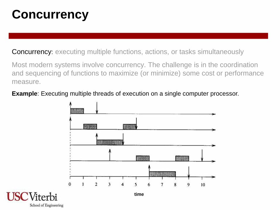
Concurrency
Concurrency: executing multiple functions, actions, or tasks simultaneously
Most modern systems involve concurrency. The challenge is in the coordination
and sequencing of functions to maximize (or minimize) some cost or performance
measure.
time
Example: Executing multiple threads of execution on a single computer processor.

Copyright © 2012 Madni-Alvidrez
Control Flow View
a1
a2
a3
a4
d1
d2
The control flow behavior model is suitable for when exact sequence of actions is
important.
It de-emphasizes data flow. action
decision
control flow

Copyright © 2012 Madni-Alvidrez
Data Flow View
The data flow behavior model is suitable for when describing data streams. It
emphasizes functional dependencies and outputs of one action must be explicitly
linked to inputs of another action. An action cannot execute until all inputs are
received.
It de-emphasizes sequencing but can be used for expressing concurrency.
function
flow
Copyright © 2012 Madni-Alvidrez
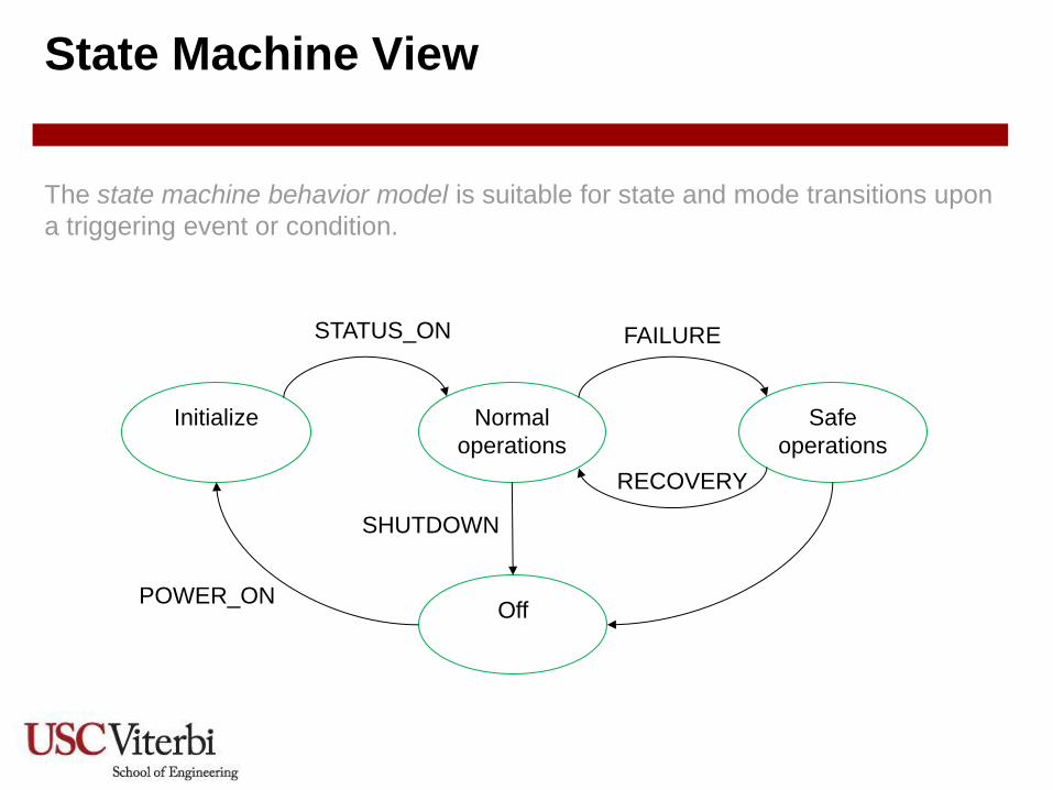
State Machine View
Initialize Normal
operations
Off
Safe
operations
STATUS_ON
POWER_ON
FAILURE
SHUTDOWN
RECOVERY
The state machine behavior model is suitable for state and mode transitions upon
a triggering event or condition.

Copyright © 2012 Madni-Alvidrez
System Engineering Activities

Copyright © 2012 Madni-Alvidrez
Systems Architecting in the Systems
Engineering Process
Architecting is the process
of developing a system
architecture.

Copyright © 2012 Madni-Alvidrez
Developing a System Architecture

Copyright © 2012 Madni-Alvidrez
Summary
• Creating a system architecture is a systems engineering function that is the
first step in translating a defined problem into a solution.
• Creating an architecture is a recursive, iterative process that begins with the
problem statement, creates some candidate solutions, assesses their merits
and chooses one.
• Architecture creation is not a deterministic process, but understanding the
strengths, weaknesses and adaptability of heritage or analogous systems is
a valuable first step.
• No one view captures an architecture. Many views are used to capture the
system structure defined in terms of system elements, interfaces, processes,
constraints, and behaviors.

Copyright © 2012 Madni-Alvidrez
• Increasing number of components in the system
• Increasing Number of interconnections and dependencies among
components
• Higher functional integration (coupling) & optimization of components
• Increasing use of immature technology & software
• Emergent behaviors
• Need for agility, robustness, resiliency, scalability, extensibility, and
efficiencies
• Humans becoming integral part of the system (need for dynamic
allocation of functions between humans and systems)
• Need for systems to work with other systems
Characteristics of System Complexity
Copyright © 2012 Madni-Alvidrez
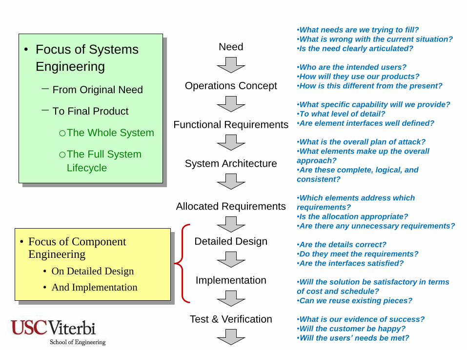
•What needs are we trying to fill?
•What is wrong with the current situation?
•Is the need clearly articulated?
•Who are the intended users?
•How will they use our products?
•How is this different from the present?
•What specific capability will we provide?
•To what level of detail?
•Are element interfaces well defined?
•What is the overall plan of attack?
•What elements make up the overall
approach?
•Are these complete, logical, and
consistent?
•Which elements address which
requirements?
•Is the allocation appropriate?
•Are there any unnecessary requirements?
•Are the details correct?
•Do they meet the requirements?
•Are the interfaces satisfied?
•Will the solution be satisfactory in terms
of cost and schedule?
•Can we reuse existing pieces?
•What is our evidence of success?
•Will the customer be happy?
•Will the users’ needs be met?
• Focus of Systems
Engineering
− From Original Need
− To Final Product
oThe Whole System
oThe Full System
Lifecycle
Need
Operations Concept
Functional Requirements
System Architecture
Allocated Requirements
Detailed Design
Implementation
Test & Verification
• Focus of Component Engineering
• On Detailed Design
• And Implementation

Copyright © 2012 Madni-Alvidrez
Systems Engineering and Classical Engineering
Disciplines Differences

Copyright © 2012 Madni-Alvidrez
Why Systems Engineering?
Increased complexity from exponential expansion of knowledge and technology
Increased complexity of products and processes
Evolution globally competitive markets and time-to-market pressures
Customers demand optimized systems and mission success
Example of
system integration
complexity
Copyright © 2012 Madni-Alvidrez
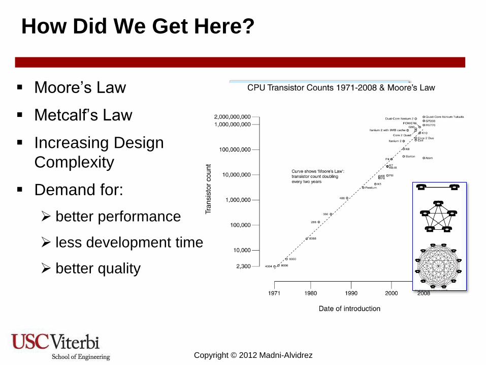
Moore’s Law
Metcalf’s Law
Increasing Design
Complexity
Demand for:
better performance
less development time
better quality
How Did We Get Here?

Copyright © 2012 Madni-Alvidrez
• Increasing number of components in the system
• Increasing Number of interconnections and dependencies among
components
• Higher functional integration (coupling) & optimization of components
• Increasing use of immature technology & software
• Emergent behaviors
• Need for agility, robustness, resiliency, scalability, extensibility, and
efficiencies
• Humans becoming integral part of the system (need for dynamic
allocation of functions between humans and systems)
• Need for systems to work with other systems
Sources of System Complexity

Copyright © 2012 Madni-Alvidrez
Managing System Complexity
To understand a system, you need to understand:
how the system will be used,
the environment in which it will operate,
the knowledge, technologies, and methods used to make it.
As systems become more complex, we need strategic ways to address
them. Key principles of managing system complexity are,
Decomposition: dividing a larger problem into manageable pieces
Abstraction: hiding unnecessary or irrelevant details
Formal analysis: formal approaches to analyses – simulation, verification, etc.

Copyright © 2012 Madni-Alvidrez
A Perspective on Design for Integrated
Hardware/Software Systems

Copyright © 2012 Madni-Alvidrez
UML Diagram Taxonomy
102
Source: http://www.uml-diagrams.org/uml-25-diagrams.html

Copyright © 2012 Madni-Alvidrez
A Taxonomy of Models
Abstract Models
Descriptive (logical)
Analytical (mathematical)
Static Dynamic
Ref: DoD. 1998. "'DoD Modeling and Simulation (M&S) Glossary" in DoD Manual
5000.59-M. Arlington, VA, USA: US Department of Defense. January 1998.
Different types of models are expressed in various languages and tools.