model based development of embedded systems 2014 · pdf fileit uppsala universitet model...
TRANSCRIPT
IT Uppsala universitet
Model Based Development of
Embedded Systems 2014 Modeling in Simulink

Modeling in Simulink
2014-09-03 Model Based Developement of Embedded Systems
Outline Modeling dynamic system Simulink basics Block Subsystem Sample time Solver Algebraic loops Simple examples

Modeling in Simulink
2014-09-03 Model Based Developement of Embedded Systems
Modeling Dynamic System
Most of the real-life systems are dynamic system Dynamic system is an entity or object that is "excited" by external input
stimuli ("inputs") and produces a response ("outputs") Input and outputs are signals of time Continuous, Discrete and Hybrid

Modeling in Simulink
2014-09-03 Model Based Developement of Embedded Systems
Modeling Dynamic System
A mathematical model of a dynamic system is described by a set of equations
At any given instant of time, these equations may be viewed as relationships between the system's output, the system's input stimuli at that time, the current state of the system, the system parameters, and time
The state of the system may be thought of as a numerical representation of the dynamically changing configuration of the system.

Modeling in Simulink
2014-09-03 Model Based Developement of Embedded Systems
Modeling Dynamic System
Differential equations Difference equations Algebric equations Composite

Modeling in Simulink
2014-09-03 Model Based Developement of Embedded Systems
Dynamic System - example
Modeling a single degree of freedom system using
2nd order differential equation

Modeling in Simulink
2014-09-03 Model Based Developement of Embedded Systems
Simulink
Simulink is a Modeling language Uses Synchronous Reactive Modeling A Simulink block diagram model is a graphical representation of a
mathematical model of a dynamic system
Purely functional: No real timing
• Computations performed in ”zero” simulated time • Pragmatically: the system response is guaranteed to be completed before the
next system event • In a block, outputs and state are computed immediately when a block is
triggered

Modeling in Simulink
2014-09-03 Model Based Developement of Embedded Systems
Simulink Block Blocks can be regular (dataflow) or Stateflow (state machine) Regular blocks can be discrete or continuous All blocks work on continuous signals, discrete blocks are activated by events Blocks can be stateless or with state
Inputs Outputs
Event

Modeling in Simulink
2014-09-03 Model Based Developement of Embedded Systems
Dynamic System - example
Lets see example of the spring damper

Modeling in Simulink
2014-09-03 Model Based Developement of Embedded Systems
Simulation Loop

Modeling in Simulink
2014-09-03 Model Based Developement of Embedded Systems
Direct Feedthrough and Sort order Computing the output of a block may need the data at input. In this case, the input port is of type ”direct feedthrough” Examples of direct feedthrough blocks Elementary math block, gain, product, etc In Model Compilation, necessary to define order of operations Simulink sorts the blocks so that blocks w. direct feedthrough inputs are
evaluated after their source blocks. Other blocks have not specified order Order can be user-specified by putting Block Priorities The lower the number, the higher the priority (Negative numbers and 0
are valid priority values)

Modeling in Simulink
2014-09-03 Model Based Developement of Embedded Systems
Block Update
Feedthrough Not Feedthrough

Modeling in Simulink
2014-09-03 Model Based Developement of Embedded Systems
Simulation Time
Selecting properly the total simulation time is important for the physical insight obtained for a simulated dynamic model
Improper time selection may lead to erroneous or incomplete conclusions Time constants of dynamic subsystems should be considered for
selecting a simulation time frame that will capture the transient and the steady state regimes
For example, a short simulation time can only reveal transient behaviors and not return the steady state condition of a stable dynamic system
The minimum total simulation time required is usually determined by the subsystem/component that has the slowest dynamics (largest time constant)

Modeling in Simulink
2014-09-03 Model Based Developement of Embedded Systems
Algebraic Loops Algebraic Loop = output goes directly to direct feedthrough input Algebraic loops arise when a model includes an algebraic constraint, F(z) = 0
Simulink tries to solve algebraic loops, but can lead to undefined behavior
Let us do an example Non Algebraic direct feedthrough loops - loops involving triggered subsytem - A loop from the output to the reset port of an integrator
Modeling in Simulink
2014-09-03 Model Based Developement of Embedded Systems
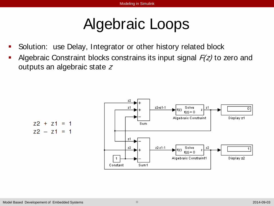
Algebraic Loops Solution: use Delay, Integrator or other history related block Algebraic Constraint blocks constrains its input signal F(z) to zero and
outputs an algebraic state z
Modeling in Simulink
2014-09-03 Model Based Developement of Embedded Systems
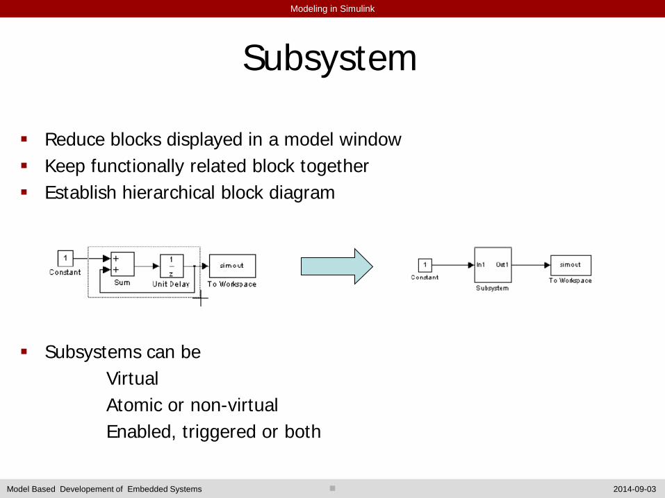
Subsystem Reduce blocks displayed in a model window Keep functionally related block together Establish hierarchical block diagram
Subsystems can be Virtual Atomic or non-virtual Enabled, triggered or both

Modeling in Simulink
2014-09-03 Model Based Developement of Embedded Systems
Atomic Subsystem

Modeling in Simulink
2014-09-03 Model Based Developement of Embedded Systems
Masking Subsystem

Modeling in Simulink
2014-09-03 Model Based Developement of Embedded Systems
Enabled and Triggered Subsytem Enabled subsystem is active when a special control signal is active Triggered subsystem is executed only when a control signal changes note: Sample time can be only constant or inherited.

Modeling in Simulink
2014-09-03 Model Based Developement of Embedded Systems
Solver Selection Mathematicians have developed a wide variety of numerical integration
techniques for solving the ordinary differential equations (ODEs) that represent the continuous states of dynamic systems
Simulink simulates a dynamic system by computing its states at successive time steps over a specified time span
Simulink provides an extensive set of fixed‐step and variable‐step continuous solvers, each implementing a specific ODE solution method

Modeling in Simulink
2014-09-03 Model Based Developement of Embedded Systems
Solver Selection

Modeling in Simulink
2014-09-03 Model Based Developement of Embedded Systems
Solver Selection Fixed‐step solvers - Solve the model at regular time intervals (time step size) from the beginning to the end of the simulation - Select a step size and hence simulation rate fast enough to track state changes in the fastest block in your model - Generally, decreasing the step size increases the accuracy of the results while increasing the time required to simulate the system
Variable‐step solvers - Vary the step size during the simulation - Reduce the step size to increase accuracy when a model's states are changing rapidly - Increase the step size to avoid taking unnecessary steps when the model's states are changing slowly
Modeling in Simulink
2014-09-03 Model Based Developement of Embedded Systems
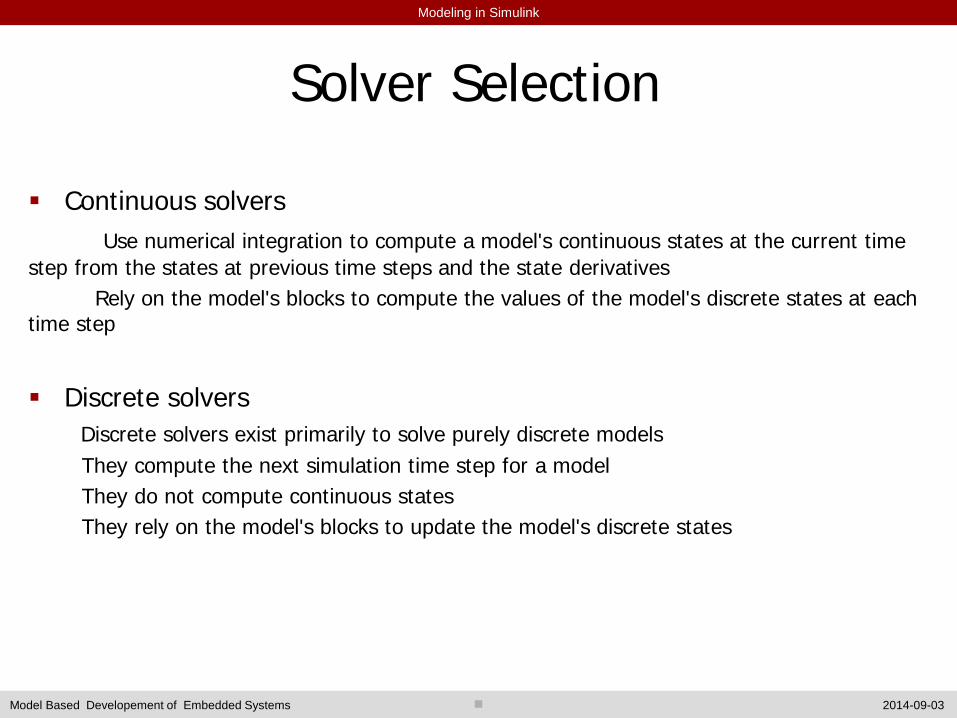
Solver Selection Continuous solvers Use numerical integration to compute a model's continuous states at the current time step from the states at previous time steps and the state derivatives Rely on the model's blocks to compute the values of the model's discrete states at each time step
Discrete solvers Discrete solvers exist primarily to solve purely discrete models They compute the next simulation time step for a model They do not compute continuous states They rely on the model's blocks to update the model's discrete states

Modeling in Simulink
2014-09-03 Model Based Developement of Embedded Systems
Variable Step size

Modeling in Simulink
2014-09-03 Model Based Developement of Embedded Systems
Sample Time Sample time specifies how often and when the block needs to be
evaluated for computing its output A continuous block has an infinitesimal sample time Many blocks allow to specify ”sample time” in Mask
• T_s sample time t_n = n*T_s T_s = 0 means ”continuous” T_s = inf means constant Sample Time T_s = -1 means ”inherited”
• [T_s,T_o] sample time with offset t_n = n*T_s + T_o
Sample time of blocks determines the fundamental sample time • GCD of sample times in system
In fixed-step simulation, auto step size gives fundamental sample time In variable-step simulation, step is adjusted fo find sample hit

Modeling in Simulink
2014-09-03 Model Based Developement of Embedded Systems
Useful Blocks

Modeling in Simulink
2014-09-03 Model Based Developement of Embedded Systems
Another Example Cruise control
http://ctms.engin.umich.edu/CTMS/index.php?example=CruiseControl&s
ection=SimulinkModeling

Modeling in Simulink
2014-09-03 Model Based Developement of Embedded Systems
Explore http://ctms.engin.umich.edu/CTMS/index.php?aux=Index_Tutorials#2 http://www.eng.ox.ac.uk/~labejp/Seminar/Simulink/Exercises.pdf http://128.173.204.63/courses/matlab/matlab_tutorial.html Embedded systems in car!
http://www.cvel.clemson.edu/auto/systems/auto-systems.html

Modeling in Simulink
2014-09-03 Model Based Developement of Embedded Systems
Next Modeling discrete systems Multirate system Library and custom blocks Function calls S function Embedded code generation More complex examples