model 720a operation and maintenance manual
TRANSCRIPT

13231 Rooster Springs Rd.,
Austin, TX 78737 T: (512) 858-4045 E: [email protected] amptec.com
AMPTEC RESEARCH
MODEL 720A OPERATION AND MAINTENANCE
MANUAL

720A Operation and Maintenance Manual – Rev S – January 25, 2019
Page 2
13231 Rooster Springs Rd., Austin, TX 78737
T: (512) 858-4045 E: [email protected] amptec.com
TABLE OF CONTENTS SECTION A: RECEIVING AND INITIAL INSPECTION
A-1 Introduction to AMPTEC 720A Digital Micro-Ohmmeter p. 3 A-2 Unpacking and Inspection p. 3 A-3 Setup and Preparation for Use p. 4
SECTION B: 720A SPECIFICATIONS B-1 Specifications for AMPTEC 720A Digital Micro-Ohmmeter p. 5 B-2 Specifications for AC Input p. 5 B-3 Specifications for AMPTEC 720A Battery Powered Version (720-BAT) p. 6
SECTION C: 720A COMPATIBLE ACCESSORY ITEMS C-1 Available Accessories and Test Leads p. 7 C-2 Options and Interfaces p. 7 C-3 Carrying Case p. 8
SECTION D: OPERATION, FEATURES, AND USE D-1 General Use p. 9 D-2 Front Panel Features p. 9
D-2.1 On/Off Switch p. 10 D-2.2 Range Switches p. 10 D-2.3 Display p. 11 D-2.3.1 Low Battery Indicator p. 11 D-2.3.2 Overload/Overrange Indicator p. 11 D-2.4 Banana Jack Terminals p. 12 D-2.5 Autorange Button and Function Information p. 12 D-2.6 Unit of Measurement LEDs p. 12
D-3 Rear Panel Features p. 13 D-3.1 Fuse Holder and Fuse Information p. 13 D-3.2 AC Inlet p. 14 D-3.3 RS-232C Terminal Block p. 14 D-3.4 RS-232C Connector p. 14 D-3.5 Fan, Fan Guard, and Air Intake p. 15 D-3.6 DC Power Jack p. 15 D-4 Battery Holder Design and Description p. 15 D-5 Test Lead Connections p. 15 D-5.1 4-wire Kelvin Information p. 16 D-6 Detailed Use Description p. 17 D-7 Detailed Use Description for RS-232C Function p. 19 D-7.1 RS-232C Commands and Data Format p. 19
SECTION E: MAINTENANCE, REPAIR, AND CALIBRATION E-1 General Maintenance, Repair, Calibration Information p. 21 E-2 Returning the 720A to AMPTEC for Maintenance, Repair, and Calibration p. 21 E-3 Basic Troubleshooting p. 22 E-3.1 Battery Replacement p. 23 E-3.2 Current Source Diagnostic Test Routine p. 24 E-3.3 Digital Voltmeter (DVM) Test Routine p. 24 E-4 720A Calibration Procedure Overview p. 24 E-4.1 Equipment Required to Complete 720A Calibration Procedure p. 25 E-4.2 Trimmer Potentiometer Adjustment Locations p. 26 E-4.3 Calibration Procedure Adjustments p. 27

720A Operation and Maintenance Manual – Rev S – January 25, 2019
Page 3
13231 Rooster Springs Rd., Austin, TX 78737
T: (512) 858-4045 E: [email protected] amptec.com
SECTION A: RECEIVING AND INITIAL INSPECTION A-1 Introduction to AMPTEC 720A Digital Micro-Ohmmeter The AMPTEC 720A Digital Micro-Ohmmeter is a seven (7) range product with 4 Wire Kelvin output, capable of making resistance measurements from 200 mΩ to 200 KΩ. The unit's high contrast LED display is readable in direct sunlight environments and displays your measurements with 4 ½ digit resolution. For automated resistance measurements, the AMPTEC 720A Digital Micro-Ohmmeter can be equipped with an optional analog output and/or RS-232C interface. The AMPTEC 720A Digital Micro-Ohmmeter can make measurements on a variety of devices, including (but not limited to) the following: Winding resistance and shorted turns of: small motors, alternators, transformers, generators, coils, solenoids, relays, wire spools, chokes, and ballasts Contact resistance of: switches, resistive trimmers, mating connectors, relay con-tacts, and circuit breakers Bonding or connection resistance measurement: any metal lo metal connection, crimp lug connections for cables, weld joints, PCB to switch or connector integrity testing, bolted joint resistance of cable connections, and earth ground testing Component testing, matching, and sorting: resistors (all types), pots, strain gouges, shunts, I.C. substrates, thick film circuits, small motors and small transformers, chokes, thermistors, fuses. extruded copper wire, Nichrome wire, all alloys of wire, healing elements, printed circuit board clad resistance, plated through holes, and plating thicknesses This meter has been specifically designed to keep reliability and ease of use in mind. Due to its integrity of measurement, ease of use, and accuracy, the AMPTEC 720A Digital Micro-Ohmmeter has become the standard for general purpose component resistance evaluation and testing. We’re extremely proud of the engineering and quality that goes into each and every one of our products we’ve created over the past 20 years. We hope you enjoy working with your 720A meter and encourage you to contact us if you have any questions or comments. Thank you for your business! A-2 Unpacking and Inspection Should the box you receive your product in be damaged upon its arrival, notify AMPTEC and the shipping carrier immediately. If your 720A meter appears damaged, the carrier’s agent should authorize repairs before the unit is returned to our facility. If the unit fails to operate or meet performance specifications (see section B) notify the carrier’s agent and AMPTEC immediately. Retain the shipping container for the carrier’s inspection.

720A Operation and Maintenance Manual – Rev S – January 25, 2019
Page 4
13231 Rooster Springs Rd., Austin, TX 78737
T: (512) 858-4045 E: [email protected] amptec.com
Do not, under any circumstance, return equipment to any of AMPTEC’s facilities or sales offices without first obtaining an RMA number (see section E) from an AMPTEC staff member. We must obtain your full contact information in order to properly coordinate the repair and return of the AMPTEC meter. A-3 Setup for Preparation and Use The following quick-step guide can be taken to power up and use the AMPTEC 720A meter:
1) The meter may be set up to operate as soon as the power is turned on, which can be accomplished by flipping the “ON/OFF” switch upwards on the unit’s front panel.
2) Allow at least fifteen (15) minutes of warm up before attempting to use the product. If the unit has been stored at a more extreme temperature, please allow up to thirty (30) minutes of warm up instead.
a. (Optional) Perform a zero check for test lead/probe integrity: i. Connect a set of leads/probes to the front panel via the VHI and
VLO banana jack terminals on the unit’s front panel. ii. Short the leads/probes by touching the ends (i.e. alligator clips,
spear tips, etc.) of each cable to each other. iii. Select the 200 Ω range on the unit’s front panel. iv. Reading should be within 5 display counts of zero.
Your 720A meter should be ready to use immediately following its warm up period. The product consumes little power and generates minimal heat. It may be used in any area where the environment does not exceed the unit’s specifications (see section B). When possible, avoid exposing the meter to extremes of temperature, which will affect accuracy and warm up time. One should become familiar with the basic test lead usage and the autorange feature (if applicable) described in detail in this manual in section D-2.4 in order to properly use the unit. For a more detailed instructional information on how to use the 720A meter, see section D-4.
720A Operation and Maintenance Manual – Rev S – January 25, 2019
Page 5
13231 Rooster Springs Rd., Austin, TX 78737
T: (512) 858-4045 E: [email protected] amptec.com
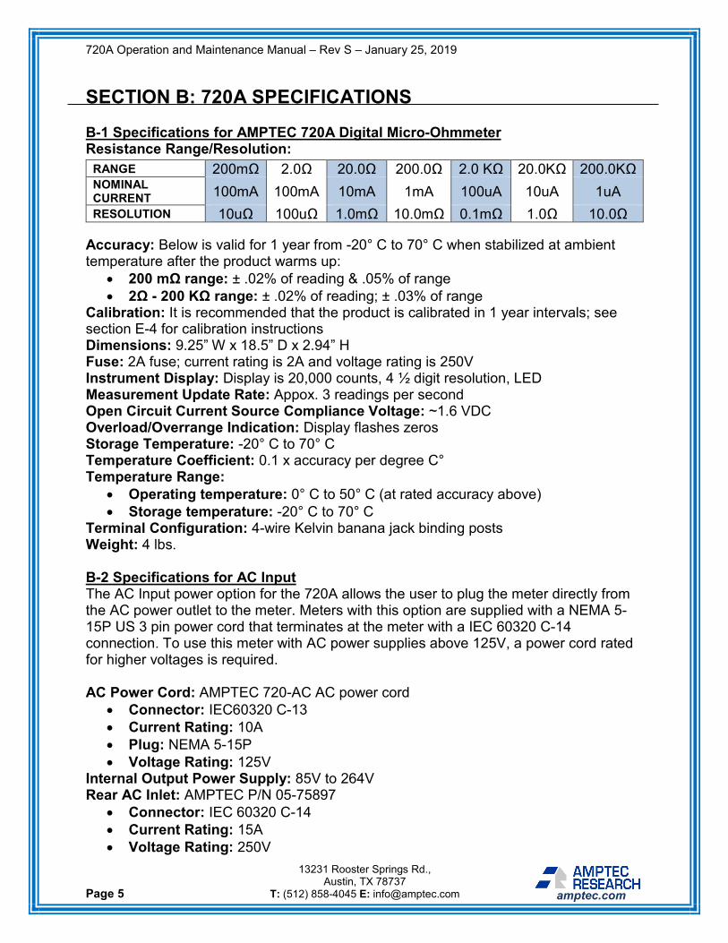
SECTION B: 720A SPECIFICATIONS B-1 Specifications for AMPTEC 720A Digital Micro-Ohmmeter Resistance Range/Resolution:
Accuracy: Below is valid for 1 year from -20° C to 70° C when stabilized at ambient temperature after the product warms up:
• 200 mΩ range: ± .02% of reading & .05% of range • 2Ω - 200 KΩ range: ± .02% of reading; ± .03% of range
Calibration: It is recommended that the product is calibrated in 1 year intervals; see section E-4 for calibration instructions Dimensions: 9.25” W x 18.5” D x 2.94” H Fuse: 2A fuse; current rating is 2A and voltage rating is 250V Instrument Display: Display is 20,000 counts, 4 ½ digit resolution, LED Measurement Update Rate: Appox. 3 readings per second Open Circuit Current Source Compliance Voltage: ~1.6 VDC Overload/Overrange Indication: Display flashes zeros Storage Temperature: -20° C to 70° C Temperature Coefficient: 0.1 x accuracy per degree C° Temperature Range:
• Operating temperature: 0° C to 50° C (at rated accuracy above) • Storage temperature: -20° C to 70° C
Terminal Configuration: 4-wire Kelvin banana jack binding posts Weight: 4 lbs. B-2 Specifications for AC Input The AC Input power option for the 720A allows the user to plug the meter directly from the AC power outlet to the meter. Meters with this option are supplied with a NEMA 5-15P US 3 pin power cord that terminates at the meter with a IEC 60320 C-14 connection. To use this meter with AC power supplies above 125V, a power cord rated for higher voltages is required. AC Power Cord: AMPTEC 720-AC AC power cord
• Connector: IEC60320 C-13 • Current Rating: 10A • Plug: NEMA 5-15P • Voltage Rating: 125V
Internal Output Power Supply: 85V to 264V Rear AC Inlet: AMPTEC P/N 05-75897
• Connector: IEC 60320 C-14 • Current Rating: 15A • Voltage Rating: 250V
RANGE 200mΩ 2.0Ω 20.0Ω 200.0Ω 2.0 KΩ 20.0KΩ 200.0KΩ NOMINAL CURRENT 100mA 100mA 10mA 1mA 100uA 10uA 1uA RESOLUTION 10uΩ 100uΩ 1.0mΩ 10.0mΩ 0.1mΩ 1.0Ω 10.0Ω

720A Operation and Maintenance Manual – Rev S – January 25, 2019
Page 6
13231 Rooster Springs Rd., Austin, TX 78737
T: (512) 858-4045 E: [email protected] amptec.com
B-3 Specifications for AMPTEC 720A Battery Powered Version (720-BAT)* Unless indicated separately below, all other specifications for the battery powered version of the 720A match those listed in section B-1. The 720-BATT power option for the 720A allows the user to power the meter with rechargeable Nickel–metal hydride (NiMH) batteries. This power option comes with a smart battery charger that has a red LED indicator when the meter is charging, and a green LED indicator when the meter is fully charged. It is safe to leave the charger plugged in even on a full charge, as the charger will adjust the output current on a full charge and not damage the batteries. Batteries: 8 D Cell NiMH; nominal capacity is 5000mAh; nominal voltage is 1.2V Battery Charger: AMPTEC 720-DC smart charger
• Battery Charger Charging Current: 800mA typical with 1A peak • Battery Charger Input Voltage: 90 VAC to 264 VAC • Battery Charger LED Indicator: black LED indicates power on but no
battery connected, red LED indicates charging, green LED indicates charged/trickle charging
• Battery Charger Output Voltage: 6.4V • Battery Charger Trickle Current: <80mA
Charge Time: Recommended 8+ hours of continuous charge to fully charge batteries Input: AC-DC adaptor, input voltage of 100V-240V AC Low Battery: Left side of display will show “-“ Weight: 5.6 lbs.

720A Operation and Maintenance Manual – Rev S – January 25, 2019
Page 7
13231 Rooster Springs Rd., Austin, TX 78737
T: (512) 858-4045 E: [email protected] amptec.com
SECTION C: 720A COMPATIBLE ACCESSORY ITEMS C-1 Available Accessories and Test Leads*
AMPTEC is also well-versed in making custom accessories and lead/probe sets. Contact us for any custom requirement you may have to see if AMPTEC can provide you with a solution. *Please note that this is not a complete list, as we offer a wide range of accessories. Contact AMPTEC to receive the most current list of 720A compatible accessory items. For pricing information on our packages, accessories, and lead/probe sets, please contact AMPTEC. C-2 Options and Interfaces*
*Please note that this is not a complete list, as we offer a wide range of options, modifications, and interfaces. Contact AMPTEC to receive the most current list of 720A compatible options.
720A Product Packages: 720A COMMERCIAL: 720A meter, lead pouch (OP-110), clip leads (OP-300), and
mini-probes (OP-403) 720A NSN: 720A meter, RS-232C interface (OP-232), autorange feature,
lead pouch (OP-110), clip leads (OP-300), and mini-probes (OP-403)
720A Meter Accessories:
OP-100: Hard shell case for meter OP-110: Test lead storage pouch 720-AC: AC power cord for the 720A meter (commercial version) 720-DC: Battery charger for the 720A meter (720-BAT version)
NIMH: Set of 8 NiMH D cell batteries
720A Compatible Test Lead/Probe Sets: OP-290: Alligator clip test lead set OP-300: Gold plated 4-wire Kelvin clip leads OP-302: 5-way banana jack backed Kelvin clips OP-401: Gold plated single tip Kelvin probes OP-402: Surface mount Kelvin micro-probes OP-403: Handheld Kelvin mini-probes
720A Compatible Options and Interfaces: OP-232: Optically isolated RS-232C interface OP-RFI: Conductive conformal coating to reduce R.F. interference
720-BAT: Battery powered version of 720A meter 720-NS: No spark version of 720A meter
720A Operation and Maintenance Manual – Rev S – January 25, 2019
Page 8
13231 Rooster Springs Rd., Austin, TX 78737
T: (512) 858-4045 E: [email protected] amptec.com
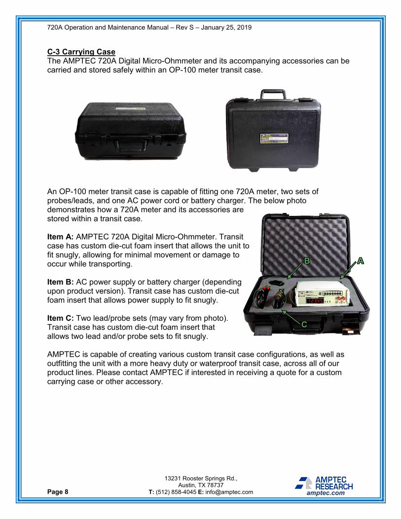
C-3 Carrying Case The AMPTEC 720A Digital Micro-Ohmmeter and its accompanying accessories can be carried and stored safely within an OP-100 meter transit case.
An OP-100 meter transit case is capable of fitting one 720A meter, two sets of probes/leads, and one AC power cord or battery charger. The below photo demonstrates how a 720A meter and its accessories are stored within a transit case. Item A: AMPTEC 720A Digital Micro-Ohmmeter. Transit case has custom die-cut foam insert that allows the unit to fit snugly, allowing for minimal movement or damage to occur while transporting. Item B: AC power supply or battery charger (depending upon product version). Transit case has custom die-cut foam insert that allows power supply to fit snugly. Item C: Two lead/probe sets (may vary from photo). Transit case has custom die-cut foam insert that allows two lead and/or probe sets to fit snugly. AMPTEC is capable of creating various custom transit case configurations, as well as outfitting the unit with a more heavy duty or waterproof transit case, across all of our product lines. Please contact AMPTEC if interested in receiving a quote for a custom carrying case or other accessory.

720A Operation and Maintenance Manual – Rev S – January 25, 2019
Page 9
13231 Rooster Springs Rd., Austin, TX 78737
T: (512) 858-4045 E: [email protected] amptec.com
SECTION D: OPERATION, FEATURES, AND USE D-1 General Use Information The AMPTEC 720A is a micro-ohmmeter designed to accurately measure low level DC resistance from 200 mΩ to 200 KΩ. The 720A meter may be used immediately after the unit has been turned on and been given a fifteen (15) minute warm up period (temperature range limits permitting). To use the 720A meter to make a resistance measurement, first connect the desired measurement leads to the appropriately colored banana jack terminals on the unit’s front panel. If your unit does not have the autorange feature, select your desired range by pressing in the push button switch that matches the value needed. If your unit has the autorange feature, you may select your desired range manually or press in the push button switch below “AUTO” and the unit will automatically select the appropriate range when it takes a measurement. Next, place the measurement leads/probes across the unknown resistance value that needs to be measured. At this point, the 720A meter should start updating the LED display once an electrical connection has been made. If your 720A is using the autorange feature, one of the three LEDs to the right of the display should indicate the unit of measurement being shown (either mΩ, Ω, or KΩ). Once the measurement leads are removed from the component that was being tested, the meter will wipe the resistance reading from the display. If you have any other general use questions, please contact AMPTEC. D-2 Front Panel Features Sub-sections D-2.1 through D-2.6 provide information on the features, design, and uses of the 720A meter’s front panel. The below photo (Figure 1) shows the details of a commercial 720A front panel. The key to the right of the front panel highlights the main features that will be described further in this section.
KEY 1 On/Off Switch
2 Range Switches
3 Display
4 Banana Jack Terminals
Figure 1 Commercial Version of 720A Front Panel

720A Operation and Maintenance Manual – Rev S – January 25, 2019
Page 10
13231 Rooster Springs Rd., Austin, TX 78737
T: (512) 858-4045 E: [email protected] amptec.com
The below photo (Figure 2) shows the details of the front panel of the NSN version of a 720A meter. There are a few key features which differ from the previous photo, and they will be described further in this section. D-2.1 On/Off Switch This switch (refer to item 1 within Figure 1 on the previous page) controls the power of the unit. When flipped upwards, the unit is on and operational. When flipped downwards, the unit is off and the only operation the unit can perform is the charging of its batteries, if equipped with the 720-BAT option. Once the switch has been flipped into the “on” position, the unit’s display should immediately light up, indicating that the unit is on and operational. If the unit’s display does not engage when the switch is flipped into the “on” position, check to ensure that the unit’s AC power cord is properly inserted into both the unit’s rear panel and a power outlet. If equipped with the 720-BAT option, this issue may indicate dead batteries, which can be resolved by charging the unit’s batteries with the power supply provided by AMPTEC. If you have continued difficulty troubleshooting a unit that won’t operate when turned on, contact AMPTEC for assistance. D-2.2 Range Switches These switches (refer to item 2 within Figure 2) control which range the unit is making measurements in. The available ranges of measurement are as follows: 200 mΩ, 2 Ω, 20 Ω, 200 Ω, 2 KΩ, 20 KΩ, and 200 KΩ. When one range button is pressed, all other buttons should be fully extended. If this is not the case, then your range switches may be broken, and you should contact AMPTEC for assistance. If you attempt to take a measurement that is too high for the range you have selected, the unit will enter overrange mode. This will be indicated by the display flashing four zeros on the screen. The unit will automatically exit overrange mode if you press the appropriate range switch for the measurement being taken. For more information on how the overrange mode works, please visit section D-2.3.2 on the following page.
KEY 5 Autorange Button
6 Unit of Measurement LEDs
Figure 2 NSN Version of 720A Front Panel

720A Operation and Maintenance Manual – Rev S – January 25, 2019
Page 11
13231 Rooster Springs Rd., Austin, TX 78737
T: (512) 858-4045 E: [email protected] amptec.com
If your unit has autorange, you can still use the range switches to manually select your range of measurement. Simply press the appropriate range switch and the unit will exit autorange mode. For more information on how the autorange feature works along with the range switches, please visit section D-2.5 on the following page. D-2.3 Display The unit features a 4 ½ digit red LED display (refer to item 3 within Figure 1 on page 9). The unit’s display should engage and light up automatically when the unit is turned on. All resistance measurements made by the unit are presented on this display up to 20,000 counts. The 720A’s display is durable and high quality, meaning it should have a life lasting many years. Should the display become damaged or stop operating properly, it can be replaced at an AMPTEC facility. D-2.3.1 Low Battery Indicator
This feature is only present in the 720-BAT version of the 720A meter. The above Figure 3 demonstrates the low battery indicator on the unit’s front panel. Whenever the unit’s batteries are nearly depleted (having only 4V or less of remaining power) the unit will indicate this with a dash appearing on the leftmost LED of the display. Once the unit’s low battery indicator is triggered, the unit has approximately 30 minutes of usage left before the batteries will be entirely depleted. D-2.3.2 Overload/Overrange Indicator If you attempt to take a measurement that is too high for the range you have selected, the unit will enter overrange mode. An example of this would be if you were to attempt measuring 500 mΩ on the 200 mΩ range. The unit’s way of letting the end user know that it is not in the correct range to take a measurement will be to enter overrange mode. Once in overrange mode, this will be indicated by the display flashing four zeros on the screen. The unit will automatically exit overrange mode if you press the appropriate range switch for the measurement being taken. If your unit has the autorange feature it will automatically select the appropriate range of measurement and will not enter overrange mode unless you are attempting to take a resistance reading over 200 KΩ.
Figure 3 Low Battery Indicator on 720A Front Panel

720A Operation and Maintenance Manual – Rev S – January 25, 2019
Page 12
13231 Rooster Springs Rd., Austin, TX 78737
T: (512) 858-4045 E: [email protected] amptec.com
D-2.4 Banana Jack Terminals These gold-plated banana jack terminals (refer to item 4 within Figure 1 on page 9) enable the end user to make 4-wire measurements by acting as connectors for cable/lead/probe sets. They are compatible with any 4-wire cable, lead, or probe set that has banana jacks. Simply connect your cable set by inserting your black cable(s) into the VLO terminals, and your red cable(s) into the VHI terminals. You may also connect bare wires to these terminals by unscrewing the plastic caps, which then exposes gold posts that the wires can be attached to. For more information on test lead connections to these terminals and how to use test leads to make measurements, refer to section D-5. D-2.5 Autorange Button and Function Information This button (refer to item 5 within Figure 2 on page 10) is only present in the NSN version of the 720A meter. Pressing this button enables the unit to automatically select its range of measurement, thus activating the unit’s autorange mode. To use this button/feature, first ensure that all other range buttons are fully extended (deselected) and press the AUTO button. If you would like to disable this feature and manually select your range of measurement, you may simply press the appropriate range switch and the autorange feature will turn off. The autorange function will automatically select the correct resistance range, given that the reading is between 0 Ω and 200 KΩ. If the reading is above 200 KΩ, the meter will enter overrange mode until a lower reading is applied or the autorange is turned off/deselected. For more information on overrange mode, see section D-2.3.2 on the previous page. D-2.6 Unit of Measurement LEDs This feature (refer to item 6 within Figure 2 on page 10) is only present in the NSN version of the 720A meter. These three LEDs indicate which unit of measurement is being displayed (either mΩ, Ω, or KΩ) when using the unit. Only one LED should be lit per measurement. No action is required by the end user to enable this feature – these LEDs should engage automatically when the unit is turned on.
720A Operation and Maintenance Manual – Rev S – January 25, 2019
Page 13
13231 Rooster Springs Rd., Austin, TX 78737
T: (512) 858-4045 E: [email protected] amptec.com
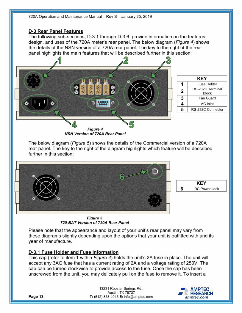
D-3 Rear Panel Features The following sub-sections, D-3.1 through D-3.6, provide information on the features, design, and uses of the 720A meter’s rear panel. The below diagram (Figure 4) shows the details of the NSN version of a 720A rear panel. The key to the right of the rear panel highlights the main features that will be described further in this section:
The below diagram (Figure 5) shows the details of the Commercial version of a 720A rear panel. The key to the right of the diagram highlights which feature will be described further in this section: Please note that the appearance and layout of your unit’s rear panel may vary from these diagrams slightly depending upon the options that your unit is outfitted with and its year of manufacture. D-3.1 Fuse Holder and Fuse Information This cap (refer to item 1 within Figure 4) holds the unit’s 2A fuse in place. The unit will accept any 3AG fuse that has a current rating of 2A and a voltage rating of 250V. The cap can be turned clockwise to provide access to the fuse. Once the cap has been unscrewed from the unit, you may delicately pull on the fuse to remove it. To insert a
KEY 1 Fuse Holder
2 RS-232C Terminal Block
3 Fan Guard
4 AC Inlet
5 RS-232C Connector
KEY 6 DC Power Jack
Figure 4 NSN Version of 720A Rear Panel
Figure 5 720-BAT Version of 720A Rear Panel

720A Operation and Maintenance Manual – Rev S – January 25, 2019
Page 14
13231 Rooster Springs Rd., Austin, TX 78737
T: (512) 858-4045 E: [email protected] amptec.com
new fuse, first ensure that the polarity of the fuse is correct, and then gently push it into the receiver on the inside of the cap. D-3.2 AC Inlet This AC inlet (refer to item 2 within Figure 4 on page 13) acts as a receiver for the AC power cord (P/N 720-AC) that comes with the unit. Once an AC power cord has been plugged into this AC inlet, you may connect its other end to an outlet. This AC inlet is an IEC 60320 C-14 connector. Its current rating is 15A and its voltage rating is 250V. If operating this unit from outside of the U.S., you may use any AC power cord that has a 60320 C-13 connector (this ensures that is compatible with the unit’s inlet) and a max voltage rating of 250V or less. D-3.3 RS-232C Terminal Block
This terminal block (refer to Figure 6 above) allows resistances readings to be taken from the rear of the meter. Each gold terminal is electrically connected to the front panel post of the same label. To take a reading from the rear panel, connect the measurement leads to each pin of the rear terminal block using the rear terminal screws shown in Figure 6. Clip or ring tongue termination ends fasten securely to the screws. Connect the opposite ends of the measurement leads to the unit under test (UUT) in the same configuration as a front panel reading. Note that the AMPTEC leads/probes supplied with your unit are not compatible with the rear panel terminal. Lastly, please note that readings taken from the front panel and the rear panel may differ from each other slightly slightly (within 5 counts). D-3.4 RS-232C Connector This connector (refer to item 4 within Figure 4 on page 13) is a DE-9 female IDC connector that supports RS-232C connections. You may use any cable that has at least one DE-9 male end to connect this port to your computer. As it is rare for modern computers to come standard with an RS-232C port, you may use an RS-232C to USB
Figure 6 Rear Terminal Block

720A Operation and Maintenance Manual – Rev S – January 25, 2019
Page 15
13231 Rooster Springs Rd., Austin, TX 78737
T: (512) 858-4045 E: [email protected] amptec.com
adapter to connect your 720A meter to your computer. Connection to this port from your computer allows you to send commands directly to your 720A meter. For more information on how to use the RS-232C function, see section D-7. D-3.5 Fan, Fan Guard, and Air Intake The fan guard (refer to item 5 within Figure 4 on page 13) protects the unit’s internal fan and prevents obstructions from the vent. It is important that you assist the fan by not unnecessarily obstructing or covering the vent while your unit is on. Additionally, the unit has seven (7) holes on the bottom plate that draw in outside air. These intake holes work with the fan to cool the unit, and it is important that they are also not obstructed or covered while operating your 720A. A unit that cannot properly intake air through the bottom holes or expel heat through the vent may overheat, which can lead to less accurate measurements. D-3.6 DC Power Jack This feature (refer to item 6 within Figure 4 on page 13) is only present in the 720-BAT battery powered version of the 720A meter. This DC power jack acts as a receiver for the battery charger (P/N 720-DC) that comes with the unit. It is through this jack that the unit receives power that charges its batteries. This DC power jack has a current rating of 5A and a voltage rating of 12V. We do not recommend attempting to charge the unit’s batteries with any charger not supplied by AMPTEC. If operating this unit from outside of the U.S., please contact AMPTEC for assistance in purchasing a different variation of charger or an outlet adaptor. D-4 Battery Holder Design and Description The battery powered version of the 720A Digital Micro-Ohmmeter has two battery holders inside which are affixed to the bottom plate of the unit. Each battery holder is made of a durable black plastic and houses 4 D cell NiMH batteries for a total of 8 batteries per unit (for more information on battery specifications see section B-3). One safety feature the unit has is a temperature fuse that is installed on each battery holder. This fuse ensures the batteries do not overheat and cause damage to the unit. Another safety feature is the addition of a flame-retardant laminate cover plate to protect the batteries from coming in contact with any leads on the PC board, which would in turn short out the unit and prevent it from functioning properly. Lastly, both battery holders are then sealed with a layer of durable fiberglass tape to prevent any battery shifting, as well as to provide a final level of protection. D-5 Test Lead Connections The AMPTEC 720A meter test lead connection uses 4 banana jack terminals on its front panel. These inputs are gold-plated and accept a variety of connections. Most commonly, cables with a banana jack on one end may easily plug into the front of these terminals. If you would like to use a different cable set that does not have banana jacks, this is achievable by unscrewing the plastic that covers these jacks. This exposes a horizontal hole through the gold-plated post which you can insert a bare wire into. Once

720A Operation and Maintenance Manual – Rev S – January 25, 2019
Page 16
13231 Rooster Springs Rd., Austin, TX 78737
T: (512) 858-4045 E: [email protected] amptec.com
the wire is through the hole in the post, you can then re-tighten the plastic by screwing it clockwise, which secures your electrical connection. The OP-300 48” gold-plated Kelvin clip lead set and the OP-403 48” Kelvin mini spear probe set that come standard with the 720A meter both plug directly into the banana jack terminals on the front panel. The spacing of the jacks only allows horizontal connection of the dual banana jack test leads to prevent misconnection. D-5.1 4-wire Kelvin Information In many resistance measurement applications, the connection contact resistance can exceed the value of the test resistance by several orders of magnitude. However, the 4 terminal configuration of the AMPTEC 720A meter eliminates measurement errors typically caused by in series test lead or test lead contact resistance. Figure 7 below and the rest of this section provide a detailed description of how this is achieved.
Figure 7 illustrates the 4-wire Kelvin principle which eliminates lead wire length and test lead connection contact resistances as potential sources of measurement errors. The internal constant current source inherently overcomes all in series resistance (within voltage compliance limits) and delivers a precise constant current. Separate DC to DC isolation circuitry provides independent circuit voltage supplies for both polarities of the constant current source circuit. The internal high impedance digital voltmeter then senses the voltage drop across the test resistance. Fundamentally, the 4-wire Kelvin resistance method avoids measurement errors induced from the resistance of the test lead/probes and the contact resistance of the lead/probes to the device under test. It doesn’t matter if the current loop is longer or if there is some contact resistance with the connection under test, because the constant current source’s compliance voltage works to maintain constant current flowing in the loop.
Figure 7 4-wire Kelvin Diagram

720A Operation and Maintenance Manual – Rev S – January 25, 2019
Page 17
13231 Rooster Springs Rd., Austin, TX 78737
T: (512) 858-4045 E: [email protected] amptec.com
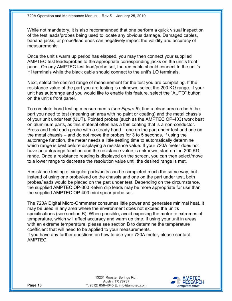
D-6 Detailed Use Description This section provides a detailed description of how to use the 720A Digital Micro-Ohmmeter to take resistance measurements.
Firstly, ensure that the unit is appropriately plugged into a power outlet. If using the 720-BAT battery powered version of the meter, it is ideal that the unit’s batteries will be charged before attempting to use the product. If your unit’s batteries are dead you can operate the meter while charging the batteries at the same time but should allow an additional ten (10) minutes in addition to the standard fifteen (15) minute warm up time before attempting to take measurements. The meter may be set up to operate as soon as the power is turned on, which can be accomplished by flipping the “ON/OFF” switch upward on the unit’s front panel. The unit’s display should engage immediately. One should allow the unit at least fifteen (15) minutes of time to warm up before attempting to make measurements. If operating a 720A meter in a more extreme climate, a warm up period of thirty (30) minutes is ideal. This warm up period allows the unit to adjust to the room’s ambient temperature and enables it to accurately take/display measurements. During this warm up period, one may also choose to perform a zero check for test lead/probe integrity if desired. Unless performing test lead/probe integrity checks, the unit should otherwise be left alone while turned on during this warm up period. (Optional) Procedure to perform a zero check on a test lead/probe set:
i. Connect a set of leads/probes to the front panel via the VHI and VLO banana jack terminals on the unit’s front panel.
ii. Short the leads/probes by touching the ends (i.e. alligator clips, spear tips, etc.) of each cable to each other.
iii. Select the 200 Ω range on the unit’s front panel. iv. Reading should be within 5 display counts of zero.
Figure 8 720A Usage Example Diagram
720A Operation and Maintenance Manual – Rev S – January 25, 2019
Page 18
13231 Rooster Springs Rd., Austin, TX 78737
T: (512) 858-4045 E: [email protected] amptec.com
While not mandatory, it is also recommended that one perform a quick visual inspection of the test leads/probes being used to locate any obvious damage. Damaged cables, banana jacks, or probe/lead ends can negatively impact the validity and accuracy of measurements. Once the unit’s warm up period has elapsed, you may then connect your supplied AMPTEC test leads/probes to the appropriate corresponding jacks on the unit’s front panel. On any AMPTEC test lead/probe set, the red cable should connect to the unit’s HI terminals while the black cable should connect to the unit’s LO terminals. Next, select the desired range of measurement for the test you are completing. If the resistance value of the part you are testing is unknown, select the 200 KΩ range. If your unit has autorange and you would like to enable this feature, select the “AUTO” button on the unit’s front panel. To complete bond testing measurements (see Figure 8), find a clean area on both the part you need to test (meaning an area with no paint or coating) and the metal chassis of your unit under test (UUT). Pointed probes (such as the AMPTEC OP-403) work best on aluminum parts, as this material often has a thin coating that is a non-conductor. Press and hold each probe with a steady hand – one on the part under test and one on the metal chassis – and do not move the probes for 3 to 5 seconds. If using the autorange function, the meter needs a little settling time to automatically determine which range is best before displaying a resistance value. If your 720A meter does not have an autorange function and the resistance value is unknown, start on the 200 KΩ range. Once a resistance reading is displayed on the screen, you can then select/move to a lower range to decrease the resolution value until the desired range is met. Resistance testing of singular parts/units can be completed much the same way, but instead of using one probe/lead on the chassis and one on the part under test, both probes/leads would be placed on the part under test. Depending on the circumstance, the supplied AMPTEC OP-300 Kelvin clip leads may be more appropriate for use than the supplied AMPTEC OP-403 mini spear probe set. The 720A Digital Micro-Ohmmeter consumes little power and generates minimal heat. It may be used in any area where the environment does not exceed the unit’s specifications (see section B). When possible, avoid exposing the meter to extremes of temperature, which will affect accuracy and warm up time. If using your unit in areas with an extreme temperature, please see section B to determine the temperature coefficient that will need to be applied to your measurements. If you have any further questions on how to use your 720A meter, please contact AMPTEC.

720A Operation and Maintenance Manual – Rev S – January 25, 2019
Page 19
13231 Rooster Springs Rd., Austin, TX 78737
T: (512) 858-4045 E: [email protected] amptec.com
D-7 Detailed Use Description for RS-232C Function The RS-232C Interface for the AMPTEC 720A Digital Micro-Ohmmeter allows the user to communicate with the meter through a serial connection from a computer. The RS-232 communication interface can be used to switch measurement ranges, query resistance readings from the meter, and read the firmware version of the meter. Any software application that can send and receive serial communication messages can be used to communicate with your 720A meter (e.g. HyperTerminal, PuTTY, Termite). Once the communication protocol settings (listed in section D-7.1) are met, the meter should be connected to a computer using a DE-9 connector. Most modern computers do not have a built-in DE-9 serial port, but a USB-to-DE-9 converter will work if properly installed. If a command is sent from the user to the meter, the meter will respond that a command has been received. To test that your unit and the computer are connected correctly, send a “V” command to read the firmware version back from the meter. Additional commands are listed in the following section D-7.1. Note: Readings taken through the RS-232C communication interface may be from either the front or rear panel. D-7.1 RS-232C Commands and Data Format This section details the commands necessary to communicate with your 720A meter via its RS-232C connection. The RS-232C communication protocol for the 720A is listed below: Baud Rate: 9600 Data Bits: 8 Stop Bits: 1 Parity: None Please note that the RS-232C Interface will not function correctly unless all the physical range selection buttons are deselected (all the way out). RS-232C Commands Please note that the following commands are case-sensitive. C Continuous Read Mode: Meter will output readings to computer for every reading
computed by the digital voltmeter (DVM). To turn this mode off, enter a ‘S’ command to switch to Single Read Mode.
S Single Read Mode: Meter will output one reading every time it receives a ‘R’
command from the computer. User must enter this command to turn off Continuous Read Mode. Meter is in Single Read Mode by default.
R Read Command: When in Single Read Mode, meter will output one reading when
this command is received. When in Continuous Read Mode, this command will not appear to have any effect.

720A Operation and Maintenance Manual – Rev S – January 25, 2019
Page 20
13231 Rooster Springs Rd., Austin, TX 78737
T: (512) 858-4045 E: [email protected] amptec.com
r0 Deselects all ranges. r1 Selects the 200 mΩ range. r2 Selects the 2 Ω range. r3 Selects the 20 Ω range. r4 Selects the 200 Ω range. r5 Selects the 2 KΩ range. r6 Selects the 20 KΩ range. r7 Selects the 200 KΩ range. Data Format The RS-232C Interface outputs reading data in the following format: 1.2345E+4 The measurement is always in ohms and the number following “E” is the exponent multiplier. For example, 1.2345E+4 is equal to 12.345 KΩ. Range Exponent 200 mΩ E-1 2 Ω E+0 20 Ω E+1 200 Ω E+2 2 KΩ E+3 20 KΩ E+4 200 KΩ E+5 Please note that an overrange reading will be indicated by 9.9999E<pn>, where p is the polarity of the exponent and n is the multiplier of the range. The range exponents are listed above.
720A Operation and Maintenance Manual – Rev S – January 25, 2019
Page 21
13231 Rooster Springs Rd., Austin, TX 78737
T: (512) 858-4045 E: [email protected] amptec.com
SECTION E: MAINTENANCE, REPAIR, AND CALIBRATION E-1 General Maintenance, Repair, and Calibration Information The AMPTEC 720A meter was designed using high quality, strong, and reliable components both internally and externally. However, as with all precise instrumentation, components may fail after prolonged periods of use. Should the unit require maintenance or repair that cannot be performed by the end user, we recommend sending the product to AMPTEC RESEARCH’s facility to perform this service. Malfunctions can sometimes simply be the result of bad test lead/connection wiring, wrong connections, misinterpretation of specifications, low battery levels, or a misunderstanding of how to use the product. The below sections will provide information on sending your unit to AMPTEC for repair, as well as how the user can perform some maintenance, troubleshooting, and calibration techniques on their own. E-2 Returning the 720A to AMPTEC for Maintenance, Repair, and Calibration AMPTEC RESEARCH has been proudly providing product support for all of our equipment for the past 20 years. Part of this support is offering maintenance, repair, and calibration services for our instrumentation. Our staff is highly trained across all our product lines and is capable of fixing nearly any issue your instrument may have. AMPTEC maintains one sole facility for both the manufacturing and repair of its products:
AMPTEC RESEARCH CORP. 13231 Rooster Springs Rd.
Austin, TX, USA 78737 Should you have a product that you would like to be sent in for maintenance, repair, or calibration, it can be sent to the address above. Before sending in a product to our facility, you must contact a member of our staff and receive an RMA #. We can be reached via email at [email protected] or phone at +1 512-858-4045. The purpose of this process is so that we can obtain your full contact information and properly coordinate the return of the AMPTEC meter after its service. Once we have received your meter, we will diagnose the issue for free and provide you with pricing information. If diagnosing the problem requires one of our technicians to open the product in order to reach the internal circuitry, a calibration fee will be required for us to send the product back to you (unless your unit is under warranty). This is because we have a plant-wide policy that all instrumentation must be calibrated before leaving our facility – as we feel it would be unethical to allow out of ordnance products to be sent to an end user.

720A Operation and Maintenance Manual – Rev S – January 25, 2019
Page 22
13231 Rooster Springs Rd., Austin, TX 78737
T: (512) 858-4045 E: [email protected] amptec.com
E-3 Basic Troubleshooting The following section will assist you in diagnosing simple problems with your 720A meter. While there are a few common errors that can be resolved by the end user, it is often recommended that you send your unit back to AMPTEC’s facility for further evaluation/repair. If in doubt simply contact us to set up the evaluation of your unit - our trained staff can quickly diagnose the problem and provide you with a simple solution. For more information on how to send your product in to our facility for evaluation and repair, please see section E-2 on the previous page. Problem: 720A meter will not turn after the on/off switch has been
flipped into the “ON” position. Possible Solutions: A. Make sure the batteries (if any) are charged and that
the correct charger/power supply is being used to power the meter. The 720A can be powered by either batteries or AC line voltage, depending upon the options purchased.
B. Ensure that the outlet being used to charge the batteries/power the unit is in proper working order. If
your outlet has a “reset” button, try pressing it and see if the unit will then respond.
C. Check that the external fuse on the rear panel is still intact. Unscrew the fuse holder on the unit’s rear panel and visually inspect the fuse inside. A blown fuse will need to be replaced but can be done so by the end user with any compatible 3AG, 2A fuse.
Problem: 720A meter will not turn on after completing steps A, B, & C. Possible Solutions: D. Further evaluation may be completed by opening up
your 720A meter. The meter’s case may be opened by first unscrewing the screws on the bottom plate of the unit inside the unit’s feet. Please note that any opening of a 720A will void its warranty and calibration (if applicable). It is highly recommended that an ESD bracelet or equivalent static discharge instrument is worm any time the circuit board of a 720A meter is being touched.
E. If you have a battery powered 720A meter, check that the batteries of the meter have not been dislodged. If
the unit has been dropped or handled very roughly during shipping, it is possible that the batteries shifted and/or dislodged, causing the 720A meter to not function properly.
F. Check that the circuit board at the front of the meter that contains the LED display digits is still plugged

720A Operation and Maintenance Manual – Rev S – January 25, 2019
Page 23
13231 Rooster Springs Rd., Austin, TX 78737
T: (512) 858-4045 E: [email protected] amptec.com
securely into the socket connecting it to the main board. Connection via this socket can shift/dislodge during shipment if the unit is handled roughly, or if the end user drops the unit.
G. Check that IC1, IC2, and IC9 are all still securely plugged into their corresponding sockets on the board. If any of these integrated circuits (ICs) have become dislodged, the meter will not function properly. These ICs may be pushed securely back into their socket(s) by hand if the user is wearing an ESD bracelet or equivalent static discharge instrument.
H. If you have completed the steps above and your 720A meter will still not turn on/operate properly, please contact AMPTEC for assistance.
Problem: My 720A’s readings are inaccurate or not within the
accuracy specifications listed in section B. Possible Solutions: A. Check the specifications listed within section B with
regards to the appropriate storage and usage temperatures for your unit. Any deviations from these temperature specifications will require the end user to, at a minimum, apply the necessary temperature coefficients to the unit’s readings and allow longer warm up times for the product.
B. Ensure that you are allowing enough time for the unit to adjust to ambient temperature before taking
readings. Under normal circumstances, the unit should be given a fifteen (15) minute warm up period, and under extreme temperatures the unit should be given at least a thirty (30) minute warm up period.
C. The unit may need to be recalibrated. If dropped or handled roughly, a 720A meter may need to be recalibrated on a shorter than annual basis. To recalibrate your 720A meter, please see section E-4.
D. If you have completed the steps above and your 720A meter is still providing inaccurate readings, please contact AMPTEC for assistance.
E-3.1 Battery Replacement Battery replacement of your 720A meter is strongly discouraged and should only be completed by qualified and authorized individuals. It is recommended that in the event of battery failure the unit is sent back to AMPTEC, where we can safely replace the batteries for you (for more information on how to send your product in for this service, see section E-2).

720A Operation and Maintenance Manual – Rev S – January 25, 2019
Page 24
13231 Rooster Springs Rd., Austin, TX 78737
T: (512) 858-4045 E: [email protected] amptec.com
If you or another authorized individual would like to replace the batteries in a 720A meter without sending the unit to our facility, please contact AMPTEC for information on how to complete this process. E-3.2 Current Source Diagnostic Test Routine The following steps can help determine if the current source circuitry is faulty:
1) Select the 2 Ω Range. 2) Put output leads across a 1 Ω resistance standard (0.005% or better). 3) Measure the voltage drop with a DC Voltmeter. It should be 0.100V.
If the above test proves untrue, then the current source circuitry is possibly faulty and may need replacing. See section E-2 for more information about sending your product in for repair. E-3.3 Digital Voltmeter (DVM) Test Routine The following steps can help determine if the DVM circuitry is faulty:
1) Select the 200 mΩ Range. 2) Short the output leads. 3) Check for a reading of 0.000 (± 5 counts). 4) Put the output leads across a 0.100 Ω resistance standard. 5) The display should read 100.00 mΩ (± 10 counts depending on the resistor’s
accuracy). If the above test proves untrue, then the DVM circuitry is possibly faulty and may need replacing. See section E-2 for more information about sending your product in for repair.
E-4 720A Calibration Procedure Overview This section of the manual contains information regarding calibration of the AMPTEC 720A Digital Micro-Ohmmeter. Total calibration of your instrument should be performed on a regular basis to ensure continued accuracy. The recommended calibration interval is 1 year, but the unit may be calibrated more often if desired. When calibrating the 720A meter, the unit should warm up for at least 30 minutes prior to calibration. If battery powered, the unit should be fully charged. If possible, the unit should ideally be calibrated in a room with optimal ambient temperature (21º - 25 º C), optimal humidity (37% - 42%), and minimal RF interference. Please note that opening of the unit in any fashion (including doing so to complete the calibration procedure) will void the unit’s warranty, so if there are concerns about voiding the warranty it is best to return the unit to AMPTEC’s facility for recalibration. More detailed instructions on how to begin the calibration procedure of your unit will commence on the following page.

720A Operation and Maintenance Manual – Rev S – January 25, 2019
Page 25
13231 Rooster Springs Rd., Austin, TX 78737
T: (512) 858-4045 E: [email protected] amptec.com
All calibration adjustment points are accessed by removing the screws within the feet on the bottom of the unit, then lifting off the top lid. Note that if your unit has an RS-232C interface you will see two PC boards when you remove the top lid. All calibration adjustments will be performed using trimmer potentiometers (referred to as trim pots in this procedure) that are on the larger PC board (also called the main board) below the RS-232C board. All trim pots used within the calibration procedure are accessible – meaning you will not need to remove the RS-232C board. Once the fifteen (15) warm up period has elapsed and you have removed the unit’s top plate, you will then connect your AMPTEC OP-300 lead set to the banana jack terminals on the unit’s front panel. Alternatively, if your precision standards have banana jack terminals, an AMPTEC OP-304 lead set may be substituted. Then, select the range you would like to calibrate (following the order outlined in the calibration adjustment in section E-4.3). Next, you will connect your lead set to that range’s corresponding resistance standard. Using a trimmer potentiometer (also referred to as trim pots) adjustment tool, you will then rotate the small screw-like component affixed to the top of each trim pot that corresponds to each range (see Figure 10). Once the unit displays the desired reading, you have finished adjusting that particular range, and you may move on to the next. Once all ranges have been calibrated, we
recommend verifying them all once more against your calibration standards before closing your unit back up. In the following subsections E-4.1 through E-4.3, you will find the locations of the trim pots as well as more detailed information about the calibration adjustments necessary to calibrate your 720A unit. E-4.1 Equipment Required to Complete 720A Calibration Procedure This section of the manual contains a list of the equipment you will need in order to calibrate the 720A Digital Micro-Ohmmeter. Precision Standard Resistors:
• One 0.001 Ω resistance standard at ± 0.01% or better accuracy • One 0.01 Ω resistance standard at ± 0.01% or better accuracy • One 0.1 Ω resistance standard at ± 0.01% or better accuracy • One 1.0 Ω resistance standard at ± 0.005% or better accuracy • One 10.0 Ω resistance standard at ± 0. 005% or better accuracy • One 100.0 Ω resistance standard at ± 0.005% or better accuracy • One 1.0 KΩ resistance standard at ± 0.005% or better accuracy • One 10.0 KΩ resistance standard at ± 0.005% or better accuracy
Figure 10 Trim Pot Adjustment Example
720A Operation and Maintenance Manual – Rev S – January 25, 2019
Page 26
13231 Rooster Springs Rd., Austin, TX 78737
T: (512) 858-4045 E: [email protected] amptec.com
Precision Standard Resistors Continued: • One 100 KΩ resistance standard at ± 0.005% or better accuracy
Other Equipment:
• One trimmer potentiometer adjustment tool • One AMPTEC OP-300 48” gold plated Kelvin clip lead set • (Optional) One AMPTEC OP-304 48” banana jack calibration lead set
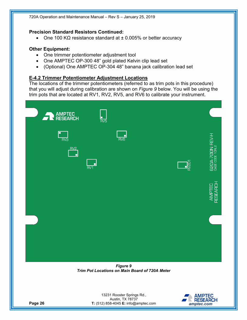
E-4.2 Trimmer Potentiometer Adjustment Locations The locations of the trimmer potentiometers (referred to as trim pots in this procedure) that you will adjust during calibration are shown on Figure 9 below. You will be using the trim pots that are located at RV1, RV2, RV5, and RV6 to calibrate your instrument.
Figure 9 Trim Pot Locations on Main Board of 720A Meter

720A Operation and Maintenance Manual – Rev S – January 25, 2019
Page 27
13231 Rooster Springs Rd., Austin, TX 78737
T: (512) 858-4045 E: [email protected] amptec.com
Trim pot at RV1: Influences full-scale on all ranges. Trim pot at RV2: Influences zero-scale on all ranges. Trim pot at RV5: Influences zero-scale on 200 mΩ range. Trim pot at RV6: Influences full-scale on 200 mΩ range. All other trim pots on the board, including RV3 and RV201 shown in Figure 9, are not used during standard product recalibration and should not be adjusted during this procedure. E-4.3 Calibration Procedure Adjustments This section contains information on the specific adjustments necessary to calibrate a 720A meter. Ensure that you have first followed the instructions detailed in the calibration procedure overview in section X before completing any of the internal adjustments below. It is recommended that you complete the following steps in order. 1. Zero Adjustment: Select the 200 Ω range. Connect the meter via the
measurement test leads across a precision 1.0 Ω resistance standard with ± 0.005% or better accuracy. Adjust the trim-pot (RV2) to make the meter read 1.00 Ω (100 counts on the display). Note that this process will be repeated on the 200 mΩ range with a 0.001 Ω standard after the full-scale adjustment is performed.
2. Full-Scale Adjustment: Connect the meter via the measurement test leads
across a precision 100 Ω resistance standard with ± 0.005% or better accuracy. Adjust the full-scale pot (RV1) to make the meter read 100.00 Ω (10000 counts on the display).
3. 200 mΩ Adjustment: Next, the 200 mΩ range needs to be calibrated. The
trim pots adjusted above (RV1 & RV2) affect every range of the meter, while RV5 & RV6 only affect the 200 mΩ range. Therefore, they must be adjusted last.
4. 200 mΩ Zero Adjustment: Select the 200 mΩ range. Connect the meter
via the measurement test leads across a precision 0.001 Ω resistance standard with ± 0.01% or better accuracy. Adjust the trim-pot (RV5) to make the meter read 01.00 mΩ (100 counts on the display).
5. 200 mΩ Full-Scale Adjustment: Connect the meter via the measurement test leads
across a precision 100 mΩ resistance standard with ± 0.005% or better accuracy. Adjust the full-scale pot (RV6) to make the meter read 100.00 mΩ (10000 counts on the display).