model 6705d model 6705dw with fast charger instruction...
TRANSCRIPT

Equipped with Electric Brake MODEL 6705D MODEL 6705DW
With Fast Charger
INSTRUCTION MANUAL
5 kg.cm - 37 kg.cm (0.4 ft.lbs - 2.7 ft.lbs) 400 3 m m ~ 5 m m
( 1 18" 3/16")
S P E C I F I CAT1 0 N S
377 m m 1.4 kg (14-13116") (3.1 Ibsl
Model 6705D
Battery Cartridge 9100
Voltage
9 6 V
Caoacities I I I I
Model DC9700 Fast Charger
Input output Charging time
A.C. only 50 Hz 60 Hr D C. 7.2 V, 9.6 V 1 Hr.
weight Overall length Fastening torque No load speed
lRPMl machine screw size

GENERAL SAFETY RULES (For All Battery Operated Tools)
WARNING! Read and understand all instructions. Failure to follow all instructions listed below, may result in electric shock, fire and/or serious personal injury.
SAVE THESE INSTRUCTIONS Work Area
Keep your work area clean and well lit. Cluttered benches and dark areas invite accidents. Do not operate power tools in explosive atmospheres, such as in the presence of flammable liquids, gases, or dust. Power tools create sparks which may ignite the dust or fumes. Keep bystanders, children, and visitors away while operating a power tool. Distractions can cause you to lose control.
Electr ical Safety A battery operated tool w i th integral batteries or a separate battery pack must be recharged only w i th the specified charger for the battery. A charger that may be suitable for one type of battery may create a risk of fire when used wi th another battery. Use battery operated tool only with specifically designated battery pack. Use of any other batteries may create a risk of fire.
Personal Safety *Stay alert, watch what you are doing, and use common sense when operating
a power tool. Do not use tool while tired or under the influence of drugs, alcohol, or medication. A moment of inattention while operating power tools may result in serious personal injury. Dress properly. Do not wear loose clothing or jewelry. Contain long hair. Keep your hair, clothing, and gloves away from moving parts. Loose clothes, jewelry, or long hair can be caught in moving parts. Avoid accidental starting. Be sure switch is in the locked or o f f position before inserting battery pack. Carrying tools wi th your finger on the switch or inserting the battery pack into a tool wi th the switch on invites accidents. Remove adjusting keys or wrenches before turning the tool on. A wrench or a key that is left attached to a rotating part of the tool may result in personal injury. Do not overreach. Keep proper footing and balance at all times. Proper footing and balance enable better control of the tool in unexpected situations. Use safety equipment. Always wear eye protection. Dust mask, non-skid safety shoes, hard hat, or hearing protection must be used for appropriate conditions.
2

Tool Use and Care Use clamps or other practical way t o secure and support the workpiece t o a stable platform. Holding the work by hand or against your body is unstable and may lead to loss of control. Do not force tool. Use the correct [tool for your application. The correct tool will do the job better and safer at the rate for which it is designed.
*Do not use tool if switch does not turn it on or off . A tool that cannot be controlled w i th the switch is dangerous and must be repaired.
*Disconnect battery pack f rom tool or place the switch in the locked or off position before making any adjustments, changing accessories, or storing the tool. Such preventive safety measures reduce the risk of starting the tool accident a I I y. Store idle tools out of reach of children and other untrained persons. Tools are dangerous in the hands of untrained users. When battery pack is not in use, keep it away f rom other metal objects like: paper clips, coins, keys, nails, screws, or other small metal objects that can make a connection from one terminal t o another. Shorting the battery terminals together may cause sparks, burns, or a fire. Maintain tools with care. Keep cutting tools sharp and clean. Properly maintained tools with sharp cutting edge are less likely t o bind and are easier t o control. Check for misalignment or binding of moving parts, breakage of parts, and any other condition that may affect the tool's operation. If damaged, have the tool serviced before using. Many accidents are caused by poorly maintained tools. Use only accessories that are recommended by the manufacturer for your model. Accessories that may be suitable for one tool may create a risk of injury when used on another tool.
Service Tool service must be performed only by qualified repair personnel. Service or maintenance performed by unqualified personnel may result in a risk of injury. When servicing a tool, use only identical replacement parts. Follow instructions in the Maintenance section of this manual. Use of unauthorized parts or failure to follow Maintenance Instructions may create a risk of shock or injury.
3

Specific Safety Rules 1. Hold tool by insulated gripping surfaces when performing an operation where
the cutting tool may contact hidden wiring. Contact wi th a "live" wire will also make exposed metal parts of the tool "live" and shock the operator.
2. Be aware that this tool is always in an operating condition, because it does not have t o be plugged into an electrical outlet.
3. Always be sure you have a firm footing. Be sure no one is below when using the tool in high locations.
4. Hold the tool firmly. 5. Keep hands away from rotating parts. 6. Do not leave the tool running. Operate the tool only when hand-held. 7. Do not touch the drill bit or the workpiece immediately after operation; they
may be extremely hot and could burn your skin.
4

SYMBOLS
The followings show the symbols used for tool.
v ................................. volts
- ................................. direct current
... /min ................................. revolutions or reciprocation per minute
5

IMPORTANT SAFETY INSTRUCTIONS
Length of Cord (Feet) 25 50
AWG Size of Cord 18 18
FOR CHARGER &
100 1 5 0
18 16
BATTERY CARTRIDGE
I. SAVE THESE INSTRUCTIONS - This manual
6

ADDITIONAL SAFETY RULES FOR CHARGER & BATTERY CARTRIDGE
1 . Do not charge Battery Cartridge when temperature is BELOW 10°C (5OOF) or ABOVE 4OoC (104OF). ,
2. Do not attempt to use a step-up transformer, an engine generator or DC power
3. Do not allow anything to cover or clog the charger vents. 4. Always cover the battery terminals with the battery cover when the battery
5. A battery short can cause a large current flow, overheating, possible burns
receptacle.
cartridge is not used.
and even a breakdown. (1 ) Do not touch the terminals with any conductive material. (2) Avoid storing battery cartridge in a container with other metal objects such
(3) Do not expose battery cartridge to water or rain.
ture may reach or exceed 5OoC (122OF).
completely worn out. The battery cartridge can explode in a fire.
as nails, coins, etc.
6. Do not store the tool and Battery Cartridge in locations where the tempera-
7. Do not incinerate the Battery Cartridge even i f it is severely damaged or is
SAVE THESE INSTRUCTIONS.
7

FUNCTIONAL DESCRIPTION Charging Plug the fast charger into your power source. Insert the battery cartridge so that the plus and minus terminals on the battery cartridge are on the same sides as their respective markings on the fast charger. Insert the cartridge fully into the port so that it rests on the charger port floor. The charging light will come on and charging will begin. If the charging light goes out soon, remove the battery cartridge from the charger and let it cool off for more than one minute. Then re-insert it and try to charge it once more. If the charging light goes out within one minute even after repeating this procedure a couple of times, the bat- tery cartridge is dead. Replace it with a new one. When the charging light goes out after about one hour, you may remove the fully charged battery cartridge. After charging, unplug the charger from the power source.
CAUTION: *The Makita fast charger DC9700 is specifically designed to charge only Makita battery cartridges. Never use it for other purposes or for other manufacturer's batteries.
*Your new battery cartridge is not charged. You will need to charge it before use. *When you charge a new battery cartridge or a battery cartridge which has not been used for a long period, it may not accept a full charge. This is a normal condition and does not indicate a problem. You can recharge the battery cartridge fully after discharging it com- pletely a couple of times.
*If you try to charge a cartridge from a just-operated tool, sometimes the charging light will not come on. If this occurs, let the cartridge cool off for a while. Then re-insert it and try to charge it once more.
*If you wish to charge two battery cartridges, allow 15 minutes between chargings on the fast charger.
8

ASSEMBLY Installing or removing the battery cartridge *Always switch off the tool before insertion or removal of the battery cartridge. *To remove the battery cartridge, ,pull out the set plate on the tool and grasp both sides of the cartridge while withdrawing it from the tool.
*To insert the battery cartridge, align the tongue on the battery cartridge with the groove in the housing and slip it into place. Snap the set plate back into place. Be sure to close the set plate fully before using the tool.
*Do not use force when inserting the bat- tery cartridge. If the cartridge does not slide in easily, it is not being inserted cor- rectly.
Installing or removing the bit CAUTION: Always be sure that the tool is switched off and the batterv cartridqe is removed before installing or removing the bit.
Use only the driver bit or socket bit shown at right. Do not use any other driver bit or socket bit.
To install the bit, pull the sleeve in the direction of the arrow and insert the bit into the sleeve as far as it will go. Then release the sleeve to secure the bit.
11 mm
g2J 9 mm
Bit I
I Sleeve
To remove the bit, pull the sleeve in the direction of the arrow and pull the bit out firmly.
NOTE: If the bit is not inserted deep enough into the sleeve, the sleeve will not return to its original position and the bit will not be secured. In this case, try re-inserting the bit accord- ing to the instructions above.
9

Switch action CAUTION: Before inserting the battery cartridge into the tool, always check to see that the switch trigger actuates properly and returns to the "OFF" position when released.
To start the tool, simply pull the trigger. Release the trigger to stop
Reversing switch action CAUTION: *Always check the direction of rotation before operation. *Use the reversing switch only after the tool comes to a complete stop. Changing the direction of rotation before the tool stops may damage the tool.
This tool has a reversing switch to change the direction of rotation. Slide the reversing switch to the A position (appear "F" mark- ing) for clockwise rotation or slide to the B position (appear " R " marking) for counter- clockwise rotation.
Reversing switch
I
Counterclock- wise rotation
Switch triggei
Overload protector The overload protector automatically cuts out to break the circuit whenever heavy work is prolonged. Wait 20 - 30 seconds before resuming operation.
10
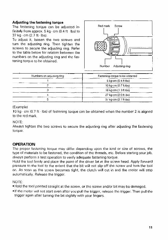
Adjusting the fastening torque The fastening torque can be adjusted in- finitely from approx. 5 kg . cm (0.4 ft . Ibs) to 37 kg . cm (2.7 ft . Ibs). To adjust it, loosen the two screws and turn the adjusting ring. Then tighten the screws to secure the adjusting ring. Refer to the table below for relation between the numbers on the adjusting ring and the fas- tening torque to be obtained.
Numbers on adjusting ring
1
2
3
4
5
Red mark Screw I
Fastening torque to be obtained
5 kg cm (0 4 R Ibs)
10 kg cm (0 7 ft Ibs) 18 kg cm (1 3 ft Ibs)
27 kg cm (2 0 ft Ibs)
37 kg cm (2 7 ft Ibs)
r '5 Number Adjusting ring
OPERATION The proper fastening torque may differ depending upon the kind or size of screws, the type of materials to be fastened, the condition of the threads, etc. Before starting your job, always perform a test operation to verify adequate fastening torque. Hold the tool firmly and place the point of the driver bit in the screw head. Apply forward pressure to the tool to the extent that the bit will not slip off the screw and turn the tool on. As soon as the screw becomes tight, the clutch will cut in and the motor will stop automatically. Release the trigger.
NOTE: *Hold the tool pointed straight at the screw, or the screw and/or bit may be damaged. *If the motor will not start even after you pull the trigger, release the trigger. Then pull the trigger again after turning the bit slightly with your fingers.
11

MAINTENANCE CAUTION : Always be sure that the tool is switched off and the battery cartridge is removed before attempting to perform inspection or maintenance.
To maintain product SAFETY and RELIABILITY, repairs, maintenance or adjustment should be performed by Makita Authorized or Factory Service Centers, always using Makita replacement parts.
Recycling the Battery The only way to dispose of a Makita battery is to recycle it. The law prohibits any other method of disposal. . I Ni-Cd
To recycle the battery:
1. Remove the battery from the tool. 2. a). Take the battery to your nearest Makita Factory Service Center
or b). Take the battery to your nearest Makita Authorized Service Center or
Distributor that has been designated as a Makita battery recycling location.
Call your nearest Makita Service Center or Distributor to determine the location that provides Makita battery recycling. See your local Yellow Pages under "Tools-Electric' :
Tips for maintaining maximum battery life 1. Charge the battery cartridge before completely discharged.
Always stop tool operation and charge the battery cartridge when you notice less tool power.
2. Never recharge a fully charged battery cartridge. Overcharging shortens the battery service life.
3. Charge the battery cartridge with room temperature at 10°C - 4OoC (50°F - 104OF). Let a hot battery cartridge cool down before charging it.
12
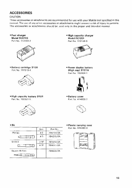
ACCESSORIES CAUTION: These accessories or attachments are recommended for use with your Makita tool specified in this manual. The use of any other accessories or attachments might present a risk of injury to persons. The accessories or attachments should be used only in the proper and intended manner.
Square drill bit
Fast charger Model DC9700 Part No. 113103-2
784606 OA
*Battery cartridge 9100 Part No. 192019.4
High capacity battery 9101 Part No. 192321-5
Bit
Part No
Phillips
c 1 r:1 784215-0A
Slotted 1 1 784010OA
lJ ! -1 Li 78401 1 -0A
High capacity charger Model DC1201 Part No. 11 31 26-0
Power display battery (High cap) 9101A Part No 192404-1
Battery cover Part No. 414938-7
Plastic carrying case Part No. 824380-8
1 3

MAKKA LIMITED ONE YEAR WARRANTY Warranty Policy
Every Makita tool is thoroughly inspected and tested before leaving the factory. It is warranted to be free of defects from workmanship and materials for the period of ON1 YEAR from the datc of original purchase. Should any trouble develop during this one-year period, return thc COMPLETE tool, freight prcpaid, to one of Makita’s Factory or Authorized Service Centers. If inspection shows the trouble is caused by defective workmanship or material, Makita will repair (or at our option, replace) without charge.
This Warranty does not apply where: repairs have been made or attempted by others: repairs are required because of normal wear and tear.
e The tool has been abused, misused or improperly maintained; e alterations have been made to the tool.
IN NO EVENT SHALL MAKITA BE LIABLE FOR ANY INDIRECT, INCIDENTAL OR CON- SEQUENTIAL DAMAGES FROM THE SALE OR USE OF THE PRODUCT. THIS DISCLAIMER APPLIES BOTH DURING AND AFTER THETERM OF THIS WARRANTY. MAKITA DISCLAIMS LIABILITY FOR ANY IMPLIED WARRANTIES, INCLUDING IMPLIED WARRANTIES O F “MERCHANTABILITY” AND “FITNESS FOR A SPECIFIC PURPOSE,” AFTER THE ONE-YEAR TERM O F THIS WARRANTY. This Warranty gives you specific legal rights, and you may also have other rights which vary from state to state. Some states d o not allow the exclusion or limitation of incidental or consequential damages, so the above limitation or exclusion may not apply lo you. Some states do not allow limitation on how long an implied warranty lasts, so the above limitation may not apply to you.
Makita Corporation 3-11 -8, Sumiyoshi-cho, Anjo, Aichi 446-8502 Japan
8841 99 - 069 PRINTED IN JAPAN 1 9 9 9 - 6 - N