model 485f9i - amplicon · 5.3.1 u.k. mains adaptor power supply 27 ... the model 485f9i adaptor is...
TRANSCRIPT

Model 485F9i
Page 1
MODEL 485F9i
OPTO-ISOLATED SIGNAL LEVEL
ADAPTOR RS-232
TO RS-422/485
This Instruction Manual is supplied with the Model 485F9i Adaptor to provide the user with sufficient information to utilise the purchased product in a proper and efficient manner. The information contained has been reviewed and is
believed to be accurate and reliable, however Amplicon Liveline Limited accepts no responsibility for any problems caused by errors or omissions. Specifications and instructions are subject to change without notice.
Model 485F9i Instruction Manual Part Nº 859 932 24 I ssue B5
© Amplicon Liveline Limited
Prepared by D.N. Cooper
Approved for issue by A.S. Gorbold, Operations Director

Model 485F9i
Page 2
DECLARATION OF CONFORMITY
AMPLICON LIVELINE LIMITED CENTENARY INDUSTRIAL ESTATE
HOLLINGDEAN ROAD BRIGHTON BN2 4AW UK
We declare that the product(s) described in this Instruction Manual are manufactured by Amplicon Liveline Limited and perform in conformity with the following standards or standardisation documents:
Electro Magnetic Compatibility (EMC):
EMC Directive 89/336/EEC LVD Directive 73/23/EEC CE Directive 93/68/EEC
Jim Hicks, I. Eng, MIEIE Managing Director
Amplicon Liveline Limited

Model 485F9i
Page 3
Model 485F9i
Opto-isolated RS-232 to RS-422/485 Adaptor
LIST OF CONTENTS
PARA SUBJECT PAGE
1 INTRODUCTION .............................................................................................................................. 5 1.1 General Description .................................................................................................................. 5 1.2 Technical Features.................................................................................................................... 5 1.3 Important Notes for Existing Model 485 Users ......................................................................... 6 1.4 What the Package Contains ..................................................................................................... 6 1.5 The Amplicon Warranty Covering the Model 485F9i Adaptor .................................................. 7 1.6 Contacting Amplicon Liveline Limited for Support or Service ................................................... 7
1.6.1 Technical Support 7 1.6.2 Repairs 7
2 INSTALLATION INSTRUCTIONS .................................................................................................... 8 2.1 Requirements of Host Equipment ............................................................................................. 8 2.2 Connections to Model 485F9i Adaptor...................................................................................... 8
2.2.1 RS-232 Connections on 9 way D Connector 8 2.2.2 RS-422/485 Connections on 8 way Pluggable Terminal Strip 9
2.3 Configuration of Model 485F9i Adaptor Options ....................................................................... 9 2.4 Full Duplex / Half Duplex Operation ........................................................................................ 11
2.4.1 Selection of Full/Half Duplex 11 2.5 Selection of Transmit Enable Control Signal .......................................................................... 12 2.6 Transmission Line Termination ............................................................................................... 13
2.6.1 Network Biasing Resistors 13 2.7 RS-232 Level Configuration .................................................................................................... 14 2.8 Power Requirements............................................................................................................... 14
2.8.1 Connecting the Amplicon Mains Adaptors 15 2.9 Software Installation ................................................................................................................ 15 2.10 Installation Testing .................................................................................................................. 15
3 APPLICATION INFORMATION ..................................................................................................... 16 3.1 Why Isolate? ........................................................................................................................... 16 3.2 Applicable Standards .............................................................................................................. 18 3.3 RS-232 Application Notes ....................................................................................................... 18
3.3.1 Electrical Levels 18 3.3.2 9/25 way Adaptors 19
3.4 RS-422/485 Application Notes ................................................................................................ 19 3.4.1 RS-422/485 Signalling Sense 19 3.4.2 RS-422/485 Parameters 20 3.4.3 Cabling of RS-422/485 Bus 20 3.4.4 Multi-drop Applications 21 3.4.5 Bus Termination 22
4 TESTING AND TROUBLESHOOTING .......................................................................................... 23 4.1 Basic Testing and Fault Isolation ............................................................................................ 23
4.1.1 Testing with the Application Software 23 4.1.2 Testing with the supplied software 23 4.1.3 Further Investigations 24
5 TECHNICAL INFORMATION ......................................................................................................... 25 5.1 Technical Specification ........................................................................................................... 25

Model 485F9i
Page 4
5.1.1 Electrical Specification 25 5.1.2 Physical/Environmental Specification 25
5.2 Circuit Details .......................................................................................................................... 26 5.2.1 Component Layouts 26 5.2.2 Circuit Operation 26
5.3 Optional Accessories .............................................................................................................. 27 5.3.1 U.K. Mains Adaptor Power Supply 27
LIST OF FIGURES FIG Nº TITLE PAGE
Figure 2.1 RS-232 CONNECTIONS 8 Figure 2.2 RS-422/485 CONNECTIONS 289 Figure 2.3 OPENING THE PLASTIC CASE 9 Figure 2.4 CONNECTIONS FOR FULL AND HALF DUPLEX OPERATION 11 Figure 2.5 EXTERNAL TRANSMITTER ENABLE CONNECTIONS 12 Figure 2.6 NETWORK BIASING RESISTORS 14 Figure 2.7 POWER SUPPLY CONNECTIONS FOR SINGLE MODEL 485F9i ADAPTOR 14 Figure 3.1 ELIMINATION OF INTERFERING SIGNALS BY ISOLATION 17 Figure 3.2 DTE ADAPTOR - 9 Way to 25 Way 19 Figure 3.3 STANDARD RS-232/422/485 PARAMETERS 20 Figure 3.4 RS-422 CONNECTED IN BROADCAST MODE 21 Figure 3.5 RS-485 CONNECTED IN MULTI-DROP, HALF DUPLEX MODE 22 Figure 4.1 TERMINAL LINKS FOR LOOP-BACK TEST 23 Figure 5.1 MODEL 485F9i Layout 28 Figure 5.2 MODEL 485F9i PRINTED CIRCUIT BOARD LAYOUT 28

Model 485F9i
Page 5
1 INTRODUCTION
1.1 GENERAL DESCRIPTION
The Model 485F9i Adaptor is a compact, plug-in unit providing fully isolated , bi-directional conversion of serial data communications signals between the following standards:- The Model 485F9i Adaptor is equipped with a 9 way, female D type connector for direct plug-in connection to an RS-232 device configured as DTE, such as a Personal Computer. When properly powered from an external, isolated supply, the adaptor translates the bi-directional transmit and receive signal levels from one standard to the other. The RS-232 device hardware handshaking lines are looped back, and the RS-232 Request To Send (RTS) control line can be used for RS-485 transmission turnaround if required. The pin-out configuration is in accordance with the RS-232 9 pin standard. The adaptor itself is not considered as DTE or DCE, and where these terms are used, they apply to the RS-232 equipment to which the Model 485F9i Adaptor is connected. A high level of electrical isolation is provided between the two ports, with each port referred to its own ground potential. Isolation is provided by opto-couplers on data and control signal lines, and the Model 485F9i Adaptor will tolerate noise or offset between PC and isolated ground terminals of 75 Vpk without data corruption. RS-485 multi-drop operation allows up to 32 devices to be connected in a simple network on a single serial bus. The transmitter has a tri-state output and may be disabled to allow reception over the same wire pair. The high impedance state (transmitter disabled) is commanded from an external control signal or from the host computer RTS line. DC power for the Model 485F9i Adaptor must be applied from an external, isolated source. The DC power is referred to the RS-422/485 ground of the remote device, and the DC power lines plus the RS-422/485 data and control signals are connected through a pluggable 8 way screw terminal assembly at the free end of the Adaptor. EMC Considerations In order to maintain compliance with the EMC directive, 89/336/EEC, it is mandatory that the final system integrator uses good quality screened cables for external connections. It is up to the final system integrator to ensure that compliance with the Directive is maintained. Amplicon Liveline offers a series of good quality screened cables for this purpose. Please contact our sales staff.
1.2 TECHNICAL FEATURES
• Full opto-isolation between the RS-232 and RS-422/485 ports • RS-422 or RS-485 compatible • Multi-drop capability • Plugs directly into standard 9 pin male connector • Configured for operation with DTE host • Single power supply connection. Polarity protected • Remote connections via pluggable terminal strip • Compact and versatile
RS-232 RS-422 OR RS-232 RS-485

Model 485F9i
Page 6
1.3 IMPORTANT NOTES FOR EXISTING MODEL 485 USERS
1. For enhanced ESD protection, the Model 485F9i Adaptor has the RS-422/485 interface ground connections on the outer pins. This requires minor wiring changes for existing users of earlier, non-isolated versions of the Amplicon 485 Adaptors
2. For conformance with the latest RS-422/485 standard specifications, the nomenclature of the data lines is amended. The RS-422/485 levels and polarities remain unchanged and the actual external data bus wiring needs no changes
3. To take advantage of the isolation provided by the 485F9i, care must be taken to ensure that the external power source maintains the isolation
4. The RS-232 interface is self-powered and this feature relies on the RTS and/or DTR control lines providing the necessary drive for the data signals. RTS and/or DTR must therefore be programmed ON (positive control signal output) for the Model 485F9i to operate correctly. Some RS-232 devices fall short of the published specifications for transmit and/or receive operations, and these devices may fail to operate with the 485F9i
1.4 WHAT THE PACKAGE CONTAINS
Some of the components on the board are susceptible to electrostatic discharge, and proper handling precautions should be observed. As a minimum, an earthed wrist strap must be worn when handling the 485F9i Adaptor outside its protective bag. Full static handling procedures are defined in British Standards Publication BSEN100015/BSEN100015-1:1992. When removed from the bag, inspect the board for any obvious signs of damage and notify Amplicon if such damage is apparent. Do not apply power to a damaged board and do not plug it into the host computer. Keep the protective bag for possible future use in transporting the module.
1. The Model 485F9i Adaptor board with 8 way free socket and the plastic case
disassembled. The plastic case should not be snapped together until any necessary configuration changes have been made.
The complete 485F9i Adaptor is supplied under Amplicon order code 909 932 23
2. The Amplicon Softman CD inclusive of this manual. Any additional accessories (mating gender changers, power supply etc.) may be packed separately.
! CAUTION

Model 485F9i
Page 7
1.5 THE AMPLICON WARRANTY COVERING THE MODEL 485F9I ADAPTOR This product is covered by the warranty as detailed in the Terms and Conditions stated in the current domestic or international Amplicon Liveline catalogue. Changes made in accordance with the guidelines given in this manual will not void this warranty unless any damage is a direct consequence of mishandling. DO NOT MAKE ANY MODIFICATIONS TO A PRODUCT THAT IS ON EVALUATION.
1.6 CONTACTING AMPLICON LIVELINE LIMITED FOR SUPPORT OR SERVICE The Model 485F9i Adaptor is designed and manufactured by Amplicon Liveline Ltd. Maintenance is available throughout the supported life of the product.
1.6.1 Technical Support Should the Model 485F9i Adaptor appear defective, please check the information in this manual to ensure that the product is being correctly applied. If an application problem persists, please request Technical Support on one of the following numbers:
Telephone: UK 01273 944 835 Fax: UK 01273 570 215 E-Mail [email protected] Internet www.amplicon.com
1.6.2 Repairs
If the Model 485F9i Adaptor requires repair then please return the goods enclosing a repair order detailing the nature of the fault. If the product is still under warranty, which is for a period of 12 months from the date of shipment, there will be no repair charge unless the fault has been caused by misuse. For traceability when processing returned goods, a Returned Materials Authorisation (RMA) procedure is in operation. Before returning the goods, please request an individual RMA number by contacting Amplicon Customer Services by telephone or fax on the above numbers. Give the reason for the return and, if the goods are still under warranty, the original invoice number and date. Repair turnaround time is normally five working days but the Service Engineers will always try to co-operate if there is a particular problem of time pressure. Please mark the RMA number on the outside of the packaging to ensure that the package is accepted by the Goods Inwards Department. Address repairs to: Customer Services Department AMPLICON LIVELINE LIMITED Centenary Industrial Estate Brighton, East Sussex BN2 4AW England
Model 485F9i
Page 8
2 INSTALLATION INSTRUCTIONS
2.1 REQUIREMENTS OF HOST EQUIPMENT The Model 485F9i Adaptor can be plugged into any device with an RS-232 port terminating in a 9 way D type male connector (DB-9) and configured as Data Terminal Equipment (DTE). The Adaptor can be directly plugged into this port and held in position by its jack screws. In addition to the 9 pin D connector, many RS-232 interface connectors comply with the 25 pin (DB-25) standard. DIN, mini-DIN and other types of connector are also sometimes used for RS-232 ports. If the pin connections of the host device interface are known, then enough information is given in this manual to make up a suitable adaptor connection cable. If isolation is not required, several types of 485 Adaptor are available from Amplicon Liveline Ltd to mate with male or female versions of the DB-25 connector and male versions of the standard 9 pin (DB-9) connector.
2.2 CONNECTIONS TO MODEL 485F9I ADAPTOR Connections are made to the Model 485F9i Adaptor at each end of the module, with the isolation barrier internally positioned between the two ports. The RS-232 connections are automatically made when the Adaptor is plugged into the port, and the RS-422/485 data, control and power connections must be made through a pluggable 8 way screw terminal connector assembly at the free end.
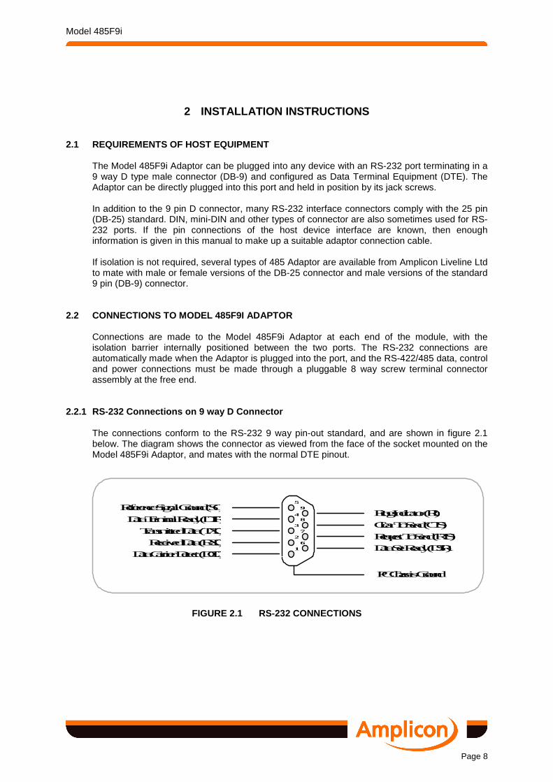
2.2.1 RS-232 Connections on 9 way D Connector The connections conform to the RS-232 9 way pin-out standard, and are shown in figure 2.1 below. The diagram shows the connector as viewed from the face of the socket mounted on the Model 485F9i Adaptor, and mates with the normal DTE pinout.
FIGURE 2.1 RS-232 CONNECTIONS
59
48
37
26
1
Ring Indicator (RI)
Clear To Send (CTS)
Request To Send (RTS)
Data Set Ready (DSR)
Reference Signal Ground (SG)
Data Terminal Ready (DTR)
Transmitted Data (TXD)
Data Carrier Detect (DCD)
Received Data (RXD)
PC Chassis Ground

Model 485F9i
Page 9
2.2.2 RS-422/485 Connections on 8 way Pluggable Ter minal Strip The DC power input, RS-485 transmission turnaround external control signal and RS-422/485 data signal connections are made via an eight way screw terminal connector. The supplied connector can be unplugged from the Adaptor for ease of making the cables without removing the Adaptor from the port. The connector pinouts are shown in figure 2.2 below. The diagram shows the connector as viewed from the top face of the Model 485F9i Adaptor. The abbreviated function names are printed on the PCB extension below the fixed part of the connector. Note that for conformance with current standards, ESD requirements and to maintain isolation, the connection configuration is similar, but not identical, to other 485 Adaptors in the Amplicon range.
FIGURE 2.2 RS-422/485 CONNECTIONS 2.3 CONFIGURATION OF MODEL 485F9I ADAPTOR OPTIONS
Configuration of the options is undertaken by cutting or soldering connections at specified points on the solder side of the Model 485F9i Adaptor printed circuit board. The Adaptor as supplied is configured to suit the majority of applications requiring full duplex operation or half duplex with echo. For convenience, the plastic case is supplied in two parts and should only be clipped together when any configuration changes have been made. Operational tests can be performed before the case is fitted. If the case halves have been snapped together, they may be parted using a small flat-bladed screwdriver to pop open the case. The technique is shown in figure 2.3 below.
FIGURE 2.3 OPENING THE PLASTIC CASE
1 GND
2 EN /TXE3 B
4 A 5 A'
6 B' 7 I.VDC
8 GND

Model 485F9i
Page 10
The configuration options listed in the table below are available, and the appropriate link positions are shown in figure 2.4.
Link Default Position
Default Function
Alternative Position
Alternative Function
Link J1 Joined RTS Tx Enable Cut External Tx Enable Link J2 Joined Rx Terminator in circuit Cut Rx Terminator out Link J3 Cut Receive enable/Echo ON Joined Half duplex echo OFF Link J4 Joined RS-232 normal sensitivity Cut RS-232 high sencitivity
The link and wiring configuration options are described in more detail in paragraphs 2.4 through 2.8. For many applications, no changes need be made, but if re-configuration is required, cut or resolder the appropriate links from figure 2.4 which diagrammatically illustrates the solder side of the printed circuit board. In the unlikely circumstance that the receiver termination resistor needs to be taken out of circuit (see para 2.7), locate the J2 pad group from figure 2.4 illustration of the non-component side of the printed circuit board. When the J2 link is not needed, cut the copper tie with a craft knife or remove any solder bridge with a desoldering tool. To re-make the link, the pads are placed close enough that a solder bridge can be re-made without using wire. Before applying power to the Adaptor, inspect the changes carefully to ensure that the solder has properly wetted the pads and that no other bridges have been made.
RX Line Terminator IN
(Default)
J2
RxD Sensitivity Normal (Default)
J4
Receive Echo ON or Receive Enable (Default condition)
J3
Transmit Enable RTS
(Default condition)
J1
GND
EN
B
A
A'
B'
VDC
GND
J4 J1
J2
J3
RX Line Terminator OUT
RxD Sensitivity High Level
Receive Echo OFF in half duplex
Transmit Enable External /TXEN
FIGURE 2.4 CONFIGURATION OPTIONS

Model 485F9i
Page 11
2.4 FULL DUPLEX / HALF DUPLEX OPERATION
The Model 485F9i Adaptor can be used in either full duplex (simultaneous transmission and reception over two independent wire pairs) or half duplex (sequential transmission or reception over a single wire pair). In full duplex operation, a separate transmitter and receiver circuit is employed, and in this mode the transmitter and receiver can be left in their enabled states at all times. In half duplex operation, the transmitter output and receiver input wire pairs are connected in parallel, and the transmitter must be disabled by switching to its high impedance state when allowing reception of data over the same serial lines. In half duplex, the receiver can either be permanently enabled (J3 cut, default) when the Tx data signals are echoed, or can be disabled during transmission (J3 joined) when the echo is suppressed. The Model 485F9i Adaptor is provided with all the data input/output terminals required for full duplex operation. If half duplex working is required, then the follow ing external and internal configuration changes must be considered. Also check that the termination resistor, paragraphs 2.6 and 3.4.5, is correctly set for the system in use.
2.4.1 Selection of Full/Half Duplex
In the full duplex condition, the serial RS-422/485 signals are transmitted over the twisted wire pair TX - A and TX - B and the incoming signals are received on RX - A' and RX - B'. In half duplex operation, the data signals are both transmitted and received on the two pairs externally wired in parallel. Figure 2.5 below illustrates the Transmit (Tx) and Receive (Rx) wiring for each mode. Jumper J3 must always be OUT for full duplex operation, but may be IN to suppress echos in half duplex operation. See the Applications Section 3 for further infdormation on wiring of the signal lines and ground connections.
FIGURE 2.4 CONNECTIONS FOR FULL AND HALF DUPLEX OPE RATION
Half Duplex Connection Transmit and Receive over same circuit
Full Duplex Connection Separate Transmit and Receive Circuits
Model 485F9i Adaptor
Tx/Rx (B) Tx/Rx (A)
I.GND 1
EN 2 TX - B 3 TX - A 4 RX - A' 5 RX - B' 6 I.VDC 7 I.GND 8
Tx (B) Tx (A) Rx (A) Rx (B)
Model 485F9i Adaptor
I.GND 1
EN 2 TX - B 3 TX - A 4 RX - A' 5 RX - B' 6 I.VDC 7 I.GND 8

Model 485F9i
Page 12
2.5 SELECTION OF TRANSMIT ENABLE CONTROL SIGNAL In half duplex operation over a single circuit or a multi-drop arrangement, the transmitter must be enabled when the device is ready to transmit, and disabled (tri-state) when the device is ready to receive. Two methods are provided for enabling the transmitter, and the desired method is selected by the Link J1. (See figure 2.4). 1. External TXEN. With the External TXEN (Not Transmit Enable) option selected on J1,
the transmit enable is under the control of a TTL level signal applied to terminal 2 (/EN) of the connector strip. This control signal is active low, and is internally pulled down when no signal is applied. In full duplex or transmit only operation, this control line can be left open-circuit, when the transmitter will be continuously enabled. THIS SIGNAL IS REFERRED TO THE POTENTIAL OF THE ISOLATED GROUND (I.GND).
In externally controlled half duplex operation, or any other situation where the transmitter
requires external control, the signal applied to terminal 1 for enabling or disabling the transmitter must not exceed the following levels:-
ENABLE TRANSMITTER '0' (Active Low) Input low > – 25 V < +0.8 V DISABLE TRANSMITTER '1' Input high (V) > +3.0 V < +25.0 V at <1.6
mA
Figure 2.6 below shows how the external control connection is made. Note that the power supply voltage VDC applied to pin 7 is in the range for disabling the transmitter, and can be used in conjunction with switch or relay contacts to turn transmission around.
FIGURE 2.5 EXTERNAL TRANSMITTER ENABLE CONNECTIONS
2. RTS Transmit Enable . The transmitter can alternatively be enabled under control of the RTS (Request To Send) line of the RS-232 host DTE device. See J1 in figure 2.4 for the appropriate jumper patching. No connection must be made to external /TXEN when RTS is controlling the transmission turnaround. In normal RS-232 DTE operation, RTS is raised to its ON (positive) state when the device is ready to commence transmission. In many circumstances, the use of RTS provides a simple means of enabling the transmitter. However, check overall system timing before using this control method.
TXEN
‘0’ Level (or open circuit) to Enable
‘1’ Level to Disable
Isolated (Remote) Ground
Transmission turn around by isolated switch or relay contacts
- Open to transmit - Closed to receive
Model 485F9i Adaptor (Viewed from top - component side)
I.GND 1
EN 2 TX - B 3 TX - A 4 RX - A' 5 RX - B' 6 I.VDC 7 I.GND 8

Model 485F9i
Page 13
An example of programming the RTS bit to effect communication turnaround is given in the following BASIC program fragment. In the normal 8250, 16450 etc type of UART, RTS is bit 1 of the Modem Control Register which is found at the channel base address BA+04. The default logic '1' at /RTS sets the transceiver to receive and the active logic '0' sets it to transmit.
regs=inp(BA+4) 'Input register contents regs=regs OR &H02 'Force bit 2 high for transmit regs=regs XOR &H02 'Force bit 2 low for receive out(BA+4),regs 'Output to modem register
When the RTS signal is being used for transmission control, the RTS output is still linked to return the signal on the CTS input lines and CTS can be monitored on bit 4 of the Modem Status Register to determine the instantaneous state of the transmission direction. Further information on half duplex and multi-drop operation is given in the applications section of this manual.
2.6 TRANSMISSION LINE TERMINATION
In RS-422 or RS-485 applications, the two wire transmission lines must be properly terminated, and a single resistor across the receiver input pair normally provides adequate termination. The Model 485F9i Adaptor is equipped with a terminator resistor for the receiver input pair, and this resistor is connected into circuit by the J2 copper link on the printed circuit board. See figure 2.4. Factory setting is with the receiver input terminator in circuit, but it can be disconnected from the circuit by cutting the link as described in paragraph 2.3. Disconnection of the termination resistor is required in some multi-drop applications. See the applications section of this manual for a discussion of bus termination.
2.6.1 Network Biasing Resistors In some instances, particularly in RS-485 multi-drop operation, noise may be detected at the receiver. In the multi-drop configuration, there can be brief periods when no transmitter is enabled, and the network is therefore allowed to float. The Model 485F9i Adaptor is protected against this condition, but other devices on the network may be susceptible to noise and are liable to float to a potential that is detected as an input. The programmer can sometimes overcome this situation by ensuring that the communications protocol flushes the input buffer until the beginning of the message flag is found. If this problem is encountered and a software solution is not viable, two extra resistors can be added externally to the 485F9i transceiver at one end of the bus, so that the network is biased to about 1 to 2 volt when all transmitters are disabled. The internal termination resistor must be kept in circuit. The arrangement is shown in figure 2.7.

Model 485F9i
Page 14
FIGURE 2.6 NETWORK BIASING RESISTORS
2.7 RS-232 LEVEL CONFIGURATION
Tests on a variety of host PCs and different RS-232 driver boards have shown that there are many creative interpretations of the RS-232 interface specification. The 485F9i Adaptor as supplied will operate correctly with the majority of known RS-232 devices, but if a problem is encountered, removing link J4 increases the output signal voltages for devices requiring these higher levels. To check the operation, run a test program, or the simple loop-back test given in paragraph 4.1.2, and view the received data. If no data or intermittent characters are received, cut link J4 and continue running the test. If characters are still not properly received, suspect another problem and refer to paragraph 4.1.3
2.8 POWER REQUIREMENTS The Model 485F9i Adaptor must be powered from an isolated external power supply providing a positive output of between +5.0 VDC and +12.0 VDC. This auxiliary power supply unit should be capable of sourcing at least 100 mA for the 485 Adaptor that it supplies. As the power supply maintains the isolation, only one 485F9i Adaptor ca n be fed from a single supply . Amplicon Mains adaptors meet these requirements and the U.K. plug-in version is available under order code 919 135 69, International wired-in version is order code 919 448 69. See paragraph 2.9.1 for information on connecting these power supplies to the Model 485F9i terminals. These mains power adaptors should not be used when the common mode potential difference across the isolation barrier is likely to exceed 75 Vpk.
FIGURE 2.7 POWER SUPPLY CONNECTIONS FOR SINGLE MODEL 485F9I ADAPTOR
ISOLATED POWER SUPPLY 5.0 to 12.0 VDC
+
–
330 Ω
180 Ω
TX - RX BUS
WIRING
Model 485F9i Adaptor
I.GND 1
EN 2 TX - B 3 TX - A 4 RX - A' 5 RX - B' 6 I.VDC 7 I.GND 8
120 Ω
Model 485F9i Adaptor
I.GND 1
EN 2 TX - B 3 TX - A 4 RX - A' 5 RX - B' 6 I.VDC 7 I.GND 8
120 Ω

Model 485F9i
Page 15
The 485F9i Adaptor is fitted with an eight way pluggable terminal strip at its free end, and the power supply should be connected to terminals 7 and 8. Terminal 8 is Isolated Ground or negative and terminal 7 is the positive supply. OBSERVE POLARITY when powering the adaptor. If the polarity is incorrect, the 485F9i Adaptor will not operate, but is protected against damage. A wiring diagram for applying power to a single 485F9i Adaptor is shown in figure 2.8.
2.8.1 Connecting the Amplicon Mains Adaptors The U.K. version of the optional mains adaptor plugs directly into a 3 pin, 13 A mains socket. The International version is fitted with a Continental 2 pin plug which, if necessary, may be cut off and a different plug fitted. The mains supply voltage must be 230 VAC ±10%, 50 Hz. The DC output is by a two wire cable approximately 2 m in length. This cable is terminated in a moulded connector which must be cut off and discarded. The two wires can then be parted and stripped back about 6 mm. The black wire is negative and goes to terminal 8 (I.GND) of the 485F9i Adaptor, and the black wire with a white stripe is positive and goes to terminal 7 (I.VDC). Section 5.3 gives the Amplicon order codes for the above adaptors.
2.9 SOFTWARE INSTALLATION
Software is not supplied with the 485F9i Adaptor, but a choice of suitable software packages is available from Amplicon Liveline Ltd. to allow easy integration of serial communications into the user's application. The 485F9i Adaptor connected via an existing RS-232 port will operate in conjunction with many commercially available communications and data acquisition packages that support RS-232, RS-422 or RS-485 serial operations. The software should be installed according to the supplier's instructions, and due note should be taken of the required settings for the communications channels, and the communications circuit configurations set accordingly. The following software limitations should be remembered when allocating COM channels:- MS-DOS 3.3 and above supports COM1, COM2, COM3 and COM4.
Other operating systems allow the use of more than two ports. Check the instructions.
Early BASIC language interpreters/compilers only support COM1 and COM2.
2.10 INSTALLATION TESTING Many applications packages include a self test feature, and when the hardware and software have been satisfactorily installed, any such test should be performed to check correct operation. If no self test is available, or a problem occurs, see the later section 4, 'TESTING AND TROUBLESHOOTING'.

Model 485F9i
Page 16
3 APPLICATION INFORMATION
As previously noted, many applications packages are designed to support data transfer over the RS-422 or RS-485 standard serial communications ports. When set up as specified, the interface will be transparent to the user. However, for special applications, particularly when isolation and the use of the RS-485 interface is required, the following notes will be helpful. 3.1 WHY ISOLATE?
The Model 485F9i Adaptor provides complete electrical isolation between any signals connected to the RS-422/485 serial port and the circuits of the host computer. In a compact office or laboratory environment such isolation may not be necessary, however in a wide-field industrial situation, serial digital communication can be disrupted by many types of contaminating signals, most of which can be eliminated by the proper use of isolation. Another common requirement for isolation occurs when one of the two connected devices has its mains supply through an earth leakage or residual current breaker. Connecting the grounds can cause the breaker to trip, and ground isolation eliminates this problem. The input receivers and output drivers make use of opto-couplers to provide a signal path between external and internal circuits without any electrical connection being made. An opto-coupler comprises a Light Emitting Diode (LED) which is turned on by the incoming signal, and a photo-detector which receives the light and converts it into an electrical signal. The emitter and detector are mounted in a package that provides a light path together with high voltage insulation between the two sides. The RS-232 interface is self-powered and the power to the RS-422/485 input/output circuits is provided by an isolated, external power supply. Interfering signals can come from a variety of sources and are often greater in amplitude than the desired signal. Such an interfering signal is 'common mode' and is effectively the potential difference between the zero-signal reference points of the signal source and receiver. By using the Model 485F9i Isolated Signal Adaptor, this potential difference appears across the isolation barrier and not in series with the signal as would be the case if direct connection was employed. The two ends of a link would normally have their grounds connected together through the signal ground line, the protective ground line and/or the cable shield. Such a connection has an impedance such that an interfering signal caused by a difference in ground potentials is likely to be a few volts in amplitude, maybe peaking to tens of volts. However there may be circumstances or fault conditions in which higher common mode voltages exist, and the circuits of the Model 485F9i Adaptor is designed to operate with peak common mode voltages up to 75 V peak without data corruption. Under fault conditions, the unit will hold off higher peak common mode voltages without damage. BE AWARE THAT THE EXTERNAL POWER SUPPLY USED WITH T HE 485F9i ADAPTOR MUST ALSO BE CAPABLE OF WITHSTANDING THE HIGH POTEN TIAL DIFFERENCE. The Mains Adaptors available from Amplicon Liveline should not be used with common mode voltages greater than 100 Vpk.
DANGER High Voltage
BE AWARE DANGER OF ELECTRIC SHOCK
When the Model 485F9i Isolated signal Adaptor is in use, voltages up to 75 Vpk or higher under fault conditions may
be exposed on the connector and associated circuitry.

Model 485F9i
Page 17
RS-232 standards allow a transition region of ±3.0 V, and within this region, signal variations will not be detected. If the signal (real or noise) is < –3.0 V, it will be detected as a mark for a data line or OFF for a control line. If the signal is > +3.0 V, it will be detected as a space for data or ON for a control signal. RS-422 and RS-485 standards provide a better level of ground noise immunity than RS-232, the maximum common mode voltages being –7.0 V to +7.0 V and –7.0 V to +12.0 V respectively for the two standards. However, any ground offset, noise, hum or other interference exceeding these peak amplitudes will be detected as real signals and corrupt the data or control functions. Breaking the common ground connection by the use of the Model 485F9i isolated interface completely eliminates the detection of these interfering signals as real signals with no loss or corruption of data. In general, isolation is only required at one end of a data link, and figure 3.1 illustrates the principle of the isolated interface and shows how the signal loop is self-contained and not subject to common mode interference. Multi-drop or broadcast systems with many RS-485 or RS-422 nodes on a single circuit may require some or all circuits to be isolated for error free serial data communication.
FIGURE 3.1 ELIMINATION OF INTERFERING SIGNALS BY IS OLATION
Tx Data
Rx Data
Signal GND Interfering signal generated
across ground-ground impedance
Non-isolated RS-422 Link with
Transmit and Receive Data Lines
Interfering signal is in
series with all data signals and will cause
corruption if the amplitude exceeds the
allowable common mode voltage levels
Remote RS-422 Device
RS-232 DTE
Interface
Loop
Tx Data
Rx Data
ISOLATED RS-422 Link with
Transmit and Receive Data Lines
Interfering signal is across the isolation barrier and NOT in series with the data lines. No corruption
occurs
Tx Data
Rx Data
IGND Signal GND
Interfering Signal
Remote RS-422 Device
RS-232 DTE
Interface
Loop
Tx Data
Rx Data
B A R R I E R

Model 485F9i
Page 18
3.2 APPLICABLE STANDARDS The prefix 'RS' signifies Recommended Standard, and the three interface types, RS-232, RS-422 and RS-485, are all well defined in the appropriate standards publications. The functions and features of the data interfaces presented by the Model 485F9i Adaptor generally conform to normal industry practice employing subsets of the full standards. The RS-232 serial interface standard is now at revision E and its full title is EIA (Electronic Industries Association) TIA RS-232-E, "Interface Between Data Terminal Equipment and Data Communication Equipment Employing Serial Data Interchange". Similar European standards CCITT V.24 and V.28 define an interface which is operationally compatible with RS-232. The RS-232 connection of the Model 485F9i Adaptor is for equipment configured as DTE (Data Terminal Equipment), and the Adaptor has a female connector. The RS-232 standard specifies a 25 pin connector, but the full 25 connector pins are not required to support the common functions of RS-232 as used by the Model 485 range of adaptors, and IBM and other manufacturers frequently adopt a 9 way D connector that provides all the necessary functionality. The Model 485F9i Adaptor complies with the 9 pin convention. Paragraph 3.3.2 gives the connection details for making up a suitable converter cable. The RS-422 interface is defined in the EIA standard RS-422-B, "Electrical Characteristics of Balanced Voltage Digital Interface Circuits". As stated, this standard defines the electrical characteristics but does not specify a connector type or pin-out configuration. The Model 485 Adaptor meets the RS-422 standard electrical specification with communication via an 8 way terminal strip connector wired as shown in the installation diagrams. The RS-485 specification is also published as an EIA standard and is closely allied to the RS-422. The 485 Adaptor meets the requirements for data signals as laid down in the standard.
3.3 RS-232 APPLICATION NOTES RS-232 was approved as a standard interface in 1969. Before and since that time, this interface in its various revisions has been very popular despite its many shortcomings and usage outside of its intended role. Most small computers now have an RS-232 interface as standard, or easily added, and many peripherals and instruments also support this serial interface, but not all in the same way. Hence an RS-232 application needs careful study of the host equipment manufacturers connections and methods before the Model 485F9i Adaptor is installed. However RS-232 lines are quite safe if wrongly connected, so the experimental use of a break-out box or 'hit and miss' methods of establishing communication can be employed.
3.3.1 Electrical Levels When checking out serial communications circuits, it is useful to know what signal levels to expect. The specified voltage levels of RS-232 data and control signals are summarised in the following table:-
Interchange Voltage –3 to –15 +3 to +15 Binary State 1 0 Data Signal (TXD) Marking Spacing Control Function (RTS, DTR) OFF ON
Signal Ground is at 0 volts, and the region between –3 and +3 volts is the transition region, but RS-232 receivers normally accept a 0 to –15 volt signal as a 1 (Marking)

Model 485F9i
Page 19
As the Model 485F9i Adaptor RS-232 interface is self powered, the host computer interface must provide at least +6.0 V output level when ON ('0' or Spacing), and the Request to Send (RTS) and/or Data Terminal Ready (DTR) control lines must be turned ON. The RS-232 receiver must accept 0±0.5 V as a '1' (Marking). These requirements are met by the all RS-232 host devices using industry standard driver/receivers. The Model 485F9i Adaptor will normally be used in close proximity to the RS-232 port, but in a case where it is not directly plugged in, any RS-232 to RS-232 connecting cable should not be more than 2 m in length
3.3.2 9/25 way Adaptors The wiring list in figure 3.1 shows the necessary connections to adapt a 9 way RS-232 port to a 25 way RS-232 port, or vice versa. Due note should be taken of the gender of the mating connector, and a gender change can be incorporated in the adaptor if required.
FIGURE 3.2 DTE ADAPTOR - 9 WAY TO 25 WAY 3.4 RS-422/485 APPLICATION NOTES
RS-422 and RS-485 have very similar characteristics, with RS-485 being compatible with, and offering all the advantages of RS-422 plus some additional capability. RS-422 pre-dated RS-485 as a standard, but RS-485 is now more popular and used in new system design. For the 485 Adaptor, the on board circuitry for the two modes is identical, the application deciding the mode of interface operation.
3.4.1 RS-422/485 Signalling Sense The RS-422 and RS-485 standards define the polarity of the signalling lines as follows, and the Model 485F9i is in accordance with these specifications.
"The signalling sense of the voltages appearing across the interconnecting cable is defined as follows:
a. The A terminal of the generator shall be negative with respect to the B terminal for a binary 1 (MARK or OFF) state
b. The A terminal of the generator shall be positive with respect to the B terminal for a binary 0 (SPACE or ON) state"
At first glance this does not appear to be correct for Amplicon devices, however one should remember this is for a TTL to 485 device, and further investigation reveals that RS 232 off state or mark is at -ve or inverted to the TTL level. This gives us a double negative state and for
8 DCD 3 Rx D 2 Tx D 20 DTR 7 SIG GND 6 DSR 4 RTS 5 CTS 22 RI
DCD 1 Rx D 2 Tx D 3 DTR 4 SIG GND 5 DSR 6 RTS 7 CTS 8 RI 9
25 WAY PIN-OUTS 9 WAY PIN-OUTS

Model 485F9i
Page 20
RS232 to RS485 devices the A terminal shall be negative w.r.t. the B terminal for a binary 0 space or on state, i.e.:- B is the invert of the incoming signal and A is the same phase.
3.4.2 RS-422/485 Parameters
The following table in figure 3.2 summarises the principal parameters of the RS-422-B and RS-485 standards, and shows RS-232 for comparison.
EIA STANDARD RS-232 RS-422-B RS-485
Mode of Operation Single ended Differential Differential Number of Drivers and
Receivers on line 1 Driver
1 Receiver 1 Driver
10 Receivers 32 Drivers
32 Receivers Max. Cable Length 15 m 1200 m 1200 m
Max. Data Rate 20 kBd 10 MBd 10 MBd Max. Common Mode N/A +7 V, –7 V +12 V, –7 V
Driver Voltage ±5 V to ±15 V ±2 V min ±1.5 V min Driver Load 3 kΩ to 7 kΩ 100 Ω min 60 Ω min
Driver Slew rate 30 V/µs N/A N/A Driver Output
Short Circuit Limit 500 mA to
Vcc or Ground 150 mA to
Ground 150 mA to Gnd 250 mA to Vcc
Receiver Input Resistance 3 kΩ to 7 kΩ 4 kΩ 12 kΩ Receiver Sensitivity ±3 V ±200 mV ±200 mV Receiver Hysteresis 1.15 V 50 mV 50 mV
FIGURE 3.3 STANDARD RS-232/422/485 PARAMETERS
3.4.3 Cabling of RS-422/485 Bus The RS-422/485 employs a differential method of signal transmission, and each bus cable has to be a wire pair, preferably twisted and screened to keep induced and radiated noise to a minimum. The bus distribution cable is effectively a transmission line, and appropriate techniques should be used for installation of the cables. In a multi-drop environment, the cable should be 'looped through' each device, or if a spur is necessary, the spur length should be kept to a minimum. Maximum end-to-end cable length and the communication baud rate are not mutually exclusive. Typical maximum transmission rates versus cable lengths are shown in the following table. The data rates applicable to the 485F9i are shown in bold type.
Transmission Rate Maximum Distance Up to 100 kBd 1200 m 115.3 kBd 1000 m 1000 kBd 100 m 10000 kBd 10 m
If screened cable is used, some thought must be given to the connection of the screen (shield). This screen should not normally be used as a ground return for non-isolated devices and it is safest to only connect the screen at a single point to the ground of one device.

Model 485F9i
Page 21
The voltage between the grounds of the various devices must not cause the common mode voltage rating of any device on the bus to be exceeded.
3.4.4 Multi-drop Applications RS-422 can provide limited multi-drop capability, using two twisted wire pairs in a broadcast mode. One wire pair connects one transmitter to multiple receivers, but if duplex operation is required, only one receiving station can answer back. See figure 3.3. Isolated or non-isolated 485 Adaptors may be used in combination in multi-drop applications. In general, if several devices are in close proximity, these devices need not be isolated as ground-ground potentials are not likely to exceed the common mode voltage limits. If one or more devices are at more remote locations, then it may be advisable to use isolated 485F9i Adaptors at these distant locations only.
FIGURE 3.4 RS-422 CONNECTED IN BROADCAST MODE
RS-485 allows multiple (up to 32) transmitters and receivers to be connected in half duplex on a single twisted wire pair for 'party line' type of communications. See figure 3.4. A method must be used to stop more than one transmitter being on the line at any time, ensuring that all other transmitters are in a high impedance state, although the circuit design is such that no damage will be done to the transceivers if several transmitters are turned on together. In a multiple RS-485 transmitter installation, the application program controls the data communication turnaround and the selection of the bus 'talker'.
Model 485F9i Isolated Adaptor
I.GND 1
EN 2 TX - B 3 TX - A 4 RX - A' 5 RX - B' 6 I.VDC 7 I.GND 8
Non- isolated
485 Adaptor
Non- isolated
485 Adaptor
GND 8 VDC 7 RX - B' 6 RX - A' 5 TX - A 4 TX - B 3 EN 2 GND 1
GND 8 VDC 7 RX - B' 6 RX - A' 5 TX - A 4 TX - B 3 EN 2 GND 1
= Twisted Pair

Model 485F9i
Page 22
FIGURE 3.5 RS-485 CONNECTED IN MULTI-DROP, HALF DUP LEX MODE Two common ways of providing program control are the 'Master / Slave' and 'Token Ring' methods. The 'Master / Slave' method designates one device on the network as Master, and this device supervises all transmissions by communicating with each of the Slaves in turn and offering it a transmission slot. In token ring operation, each device knows its ID neighbour and only talks directly to this next device. Thus communication only occurs between adjacent pairs of devices and this makes for a flexible network but can be a more difficult method to implement. The Model 485 Adaptor provides a method of communication turnaround by enabling the 'ON' transmitter using an external control signal or RTS from the RS-232 port. Default condition of the Model 485 Adaptor enables the transmitter, so that for full duplex operation of RS-422/485 no control signal is required. See paragraph 2.5 for further information.
3.4.5 Bus Termination
For proper operation of the RS-422/485 bus in full or half duplex, multi-drop or point-to-point communication, it is recommended that termination is applied to the receiver end of the data lines. The simplest form of termination is line-to-line with typically a 120 Ω resistor across the differential input, and this terminator is available on the Model 485F9i Adaptor board, selectable by link J2. In a multi-drop system, the terminator resistor is only required at the device receiver located at the far end of the cable. If this is in half duplex operation, then both ends of the bus cable are equipped with receivers (transceivers) so termination is necessary at both ends. Although the 485F9i Adaptor will drive loads as low as 27 Ω, in general, RS-485 transmitter circuits are specified as being capable of driving a minimum load resistance of 60 Ω, so no more than two terminator resistors should be connected in parallel to any one bus.
Model 485F9i Isolated Adaptor
I.GND 1
EN 2 TX - B 3 TX - A 4 RX - A' 5 RX - B' 6 I.VDC 7 I.GND 8
Non- isolated
485 Adaptor
Non- isolated
485 Adaptor
GND 8 VDC 7 RX - B' 6 RX - A' 5 TX - A 4 TX - B 3 EN 2 GND 1
GND 8 VDC 7 RX - B' 6 RX - A' 5 TX - A 4 TX - B 3 EN 2 GND 1
= Twisted Pair
Model 485F9i
Page 23
4 TESTING AND TROUBLESHOOTING 4.1 BASIC TESTING AND FAULT ISOLATION
If the installation instructions have been correctly followed, and the serial communications port is being used in conjunction with a proven software driver, then it is unlikely that any problems will be experienced in establishing communications through the serial interface. When difficulties do occur, the following notes may be helpful in isolating the problem area.
4.1.1 Testing with the Application Software
Before testing, ensure that the Model 485F9i Adaptor is properly configured for the application. Use the test mode of the application program, and If a problem occurs, it is often possible to test the system using the looped back RS-232 port without the Model 485F9i Adaptor. This test will identify that a problem is in the adaptor, its configuration or use.
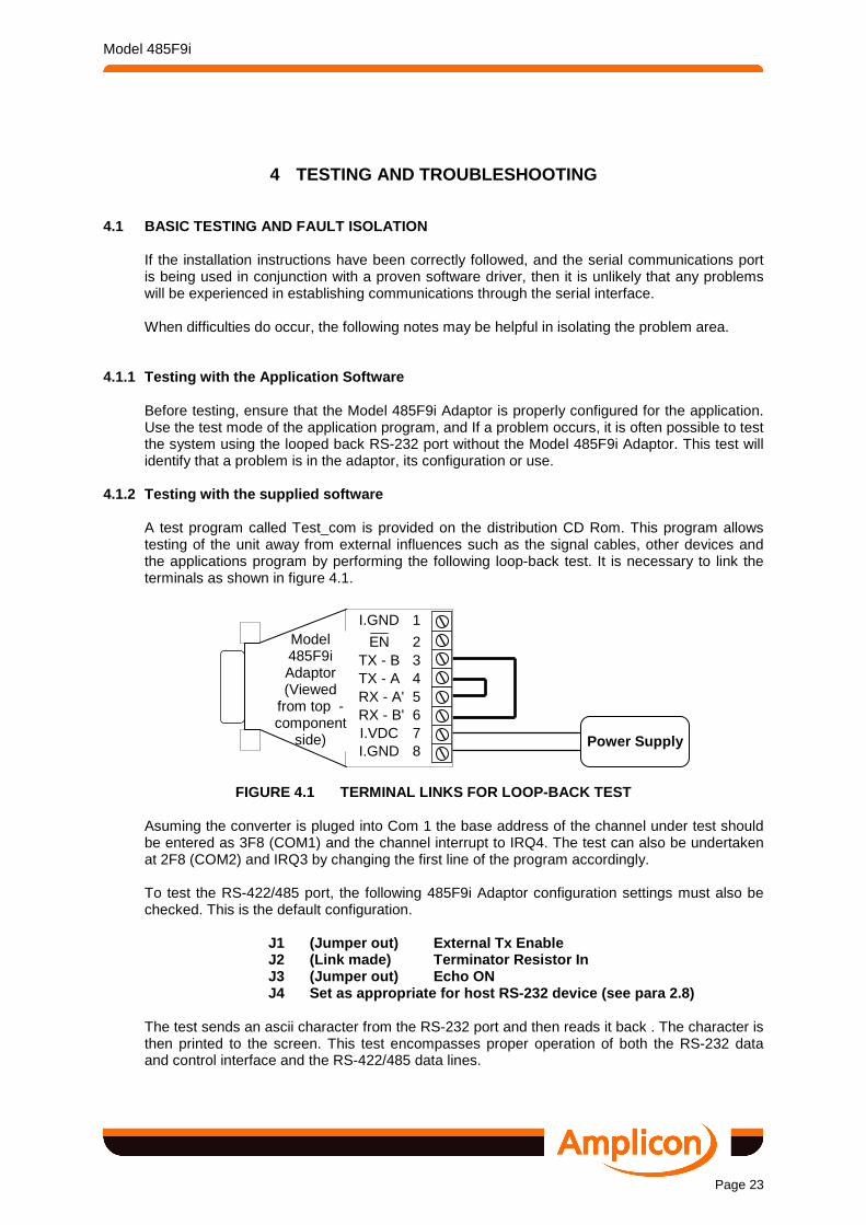
4.1.2 Testing with the supplied software A test program called Test_com is provided on the distribution CD Rom. This program allows testing of the unit away from external influences such as the signal cables, other devices and the applications program by performing the following loop-back test. It is necessary to link the terminals as shown in figure 4.1.
FIGURE 4.1 TERMINAL LINKS FOR LOOP-BACK TEST
Asuming the converter is pluged into Com 1 the base address of the channel under test should be entered as 3F8 (COM1) and the channel interrupt to IRQ4. The test can also be undertaken at 2F8 (COM2) and IRQ3 by changing the first line of the program accordingly. To test the RS-422/485 port, the following 485F9i Adaptor configuration settings must also be checked. This is the default configuration.
J1 (Jumper out) External Tx Enable J2 (Link made) Terminator Resistor In J3 (Jumper out) Echo ON J4 Set as appropriate for host RS-232 device (see p ara 2.8)
The test sends an ascii character from the RS-232 port and then reads it back . The character is then printed to the screen. This test encompasses proper operation of both the RS-232 data and control interface and the RS-422/485 data lines.
I.GND 1
EN 2 TX - B 3 TX - A 4 RX - A' 5 RX - B' 6 I.VDC 7 I.GND 8
Power Supply
Model 485F9i Adaptor (Viewed
from top - component
side)

Model 485F9i
Page 24
4.1.3 Further Investigations If tests with the applications software or other loop-back tests indicate that the 485 Adaptor is working properly, but other problems persist, then the following should be investigated. Communication circuits
For a communications circuit to operate correctly, both ends of the circuit, and the interconnecting cables must be serviceable and the correct connections made. The vagaries of RS-232, RS-422 and RS-485 implementation often cause problems in making the proper connections, and the manufacturers instructions for the equipment at each end should be carefully checked.
Hardware handshaking control signals
The self powered facility of the RS-232 interface of the 485F9i Adaptor requires that the device interface meets the minimum specification requirements and it must be ensured that Data Terminal Ready (DTR) and/or Request To Send (R TS) control lines are ON (high). If RTS is being used for transmission enable in half duplex operation, then the program must ensure that DTR is ON (high) at all times.
Polarity of RS-422/485 differential data lines
Not all suppliers use the same convention for the polarity of the differential data lines. The Model 485F9i Adaptor lines are labelled A and B for the transmitter and A' and B' for the receiver as defined in the RS-422/485 specification. If the other device is labelled differently, then:-
A is normally connected to A or A' or Y or High or + B is normally connected to B or B' or Z or Low or –
If all devices are not so labelled and the polarity is not evident, or if a problem is suspected in this area, then some experimentation may be necessary. No damage can be done to the interface hardware by reversing polarity.
Termination of Data and Control Lines
The differential data lines must be properly terminated as described in paragraph 2.7

Model 485F9i
Page 25
5 TECHNICAL INFORMATION
5.1 TECHNICAL SPECIFICATION The technical characteristics of the Model 485F9i Adaptor are in accordance with the following electrical and physical specifications. Except where otherwise noted, all specifications ar e typical at 25º C
5.1.1 Electrical Specification
External Isolated Power Requirements +5.0 VDC to +14.0 VDC from external isolated power supply via terminal strip. 100 mA required with full 485 bus load
Port to Port Isolation Voltage Maximum noise or offset between PC and isolated
ground terminals of 75 Vpk without data corruption. RS-232 Tx Data Marking (from host) < 0 V RS-232 Tx Data Spacing (from host) Must be > +5.0 V RS-232 Control Signals (RTS and DTR from host)
ON Must be > +5.0 V OFF Must be < –5.0 V
RS-232 Rx Data Marking (from 485F9i) < +1.0 V RS-232 Rx Data Spacing (from 485F9i) > +4.0 V when supplied from 9V RS-422/485 Input sensitivity 0.2 V RS-422/485 Input hysteresis 70 mV RS-422/485 Output drive 1.5 V minimum, fully loaded RS-422/485 Output load 27 Ω minimum
RS-422/485 Receiver I/P Termination 120 Ω resistor across differential input terminals. Can be disconnected by cutting link
RS-485 Tx enable >–25.0 V, < +0.8 V or open circuit RS-485 Tx disable > +3.0 V, <+25.0 V Tx disable input current <1.6 mA (Input high) Data rate 2.5MBd max RS-232 Connector 9 way DB-9 female connector with screw-locks RS-422/485 Connector 8 way pluggable screw terminal assembly
5.1.2 Physical/Environmental Specification
Module with connector Packed
Size 67 x 43 x 20 mm 215 x180 x 80 mm Weight 60 gm 250 gm
Temperature Range Operating Storage
0° C to +60° C -20 to +70° C

Model 485F9i
Page 26
5.2 CIRCUIT DETAILS Sufficient details of the Model 485F9i Adaptor circuit and its operation are given for troubleshooting and repair by the user. The circuit diagram is also useful in understanding the operation of the various optional configurations. Some of the components on the board are susceptible to electrostatic discharge, and proper handling precautions should be observed. As a minimum, an earthed wrist strap must be worn when handling the 485F9i Adaptor outside its protective bag.
5.2.1 Component Layouts The PCB Component and copper side layouts are shown in Figure 5.1 and 5.2 respectively.
5.2.2 Circuit Operation Function The Model 485F9i Adaptor converts the electrical levels of
signals from those specified for RS-232 to RS-422/485 levels and vice versa.
Isolation Electrical isolation between the ports is implemented by opto-
couplers in the transmit (QA3), receive (QA1) and RTS control circuits (QA2). Each side of the barrier is powered separately.
RS-232 Power The RS-232 side is self powered and requires that the host
device data and control signals exceed ±5.0 V for proper operation. The voltage to drive the data line is derived from RTS and/or DTR through diodes D2 and D1, and one or both of these lines must always be ON (positive) to ensure proper operation and the derived voltage must be at least +5 VDC.
RS422/485 Power The RS-422/485 side is powered by an external, isolated
power supply with regulation to +5 VDC provided by a protected series regulator Q1. This supply is referred to isolated ground, and must retain the isolation.
Hardware Handshaking The RS-232 port CTS input is linked to the RTS output to
ensure that the RS-232 operation does not lock up awaiting a handshake signal. Similar to the above, the RS-232 port DSR input is linked to the DTR output
Transmission Turnaraound With J1 out of circuit, transmission is turned round under the
control of /TXEN on PL1/2. This line is normally pulled down by R6, and the transistor embedded in QA2 inverts this signal to enable the 485 transmitter in QA4. With J1 inserted RTS can also be used for transmission turnaround in half duplex and in this case no signal must be applied to the external /TXEN control line.
Echo With J3 out, the receiver in QA4 is permanently enabled, with
incoming data always routed to the RS-232 device. This is the normal condition with full duplex operations, and in half duplex mode, both received data and transmitted data (echo) are sent to the RS-232 device. When J3 is in and the circuit is

Model 485F9i
Page 27
operating in half duplex, then the receiver in QA4 is enabled/disabled in opposite phase to the transmitter and the echo is not retuirned.
RXD Pull Down Dependant on the characteristics of the RS-232 receiver, the
pull down resistor R10, R11 can be set as 1k5 or 9k7 by the position of J4.
5.3 OPTIONAL ACCESSORIES 5.3.1 U.K. Mains Adaptor Power Supply Amplicon Order Code
Description Function
919 135 69 Plug-in mains adaptor Provides +9 VDC at 200 mA to power a Model 485F9i Adaptor. Mains operated 230/240 VAC. Integral 3 pin, 13 A, UK style plug. Two wire output cable of 2 m length. Moulded connector to be removed for screw terminal connection to 485F9i Adaptor. Wire with white stripe is positive, see paragraph 2.4.1
The U.K. Mains Adaptor complies with the requirements of British Standard BS415
5.3.2 International Mains Adaptor Power Supply
919 448 69 Wired-in mains adaptor Provides +9 VDC at 200 mA to power a Model 485F9i Adaptor. Mains operated 220/230 VAC. Two wire (Brown - live, blue - neutral), 1.5 m length mains input cable fitted with two pin 'Continental' mains plug. Two wire output cable of 2 m length. Moulded power connector to be removed for screw terminal connection to 485F9i Adaptor. Wire with white stripe is positive, see paragraph 2.4.1

Model 485F9i
Page 28
FIGURE 5.1 MODEL 485F9I LAYOUT
FIGURE 5.2 MODEL 485F9I PRINTED CIRCUIT BOARD LAYOU T
COMPONENT SIDE
AM
PLI
CO
N L
IVE
LIN
E 9
9322
1 C
/S IS
SU
E A
PL1
SOLDER SIDE
J2 R12 R8
R10
R3
R11 U4
J1
J3
J4
R10
C4
B A
A'
B'