model 3000 series operation manual...model 3000 series . ... this product will perform in conformity...
TRANSCRIPT
Part No. 2718-55-16
OPERATION MANUAL
© 2010 IVY Biomedical Systems Inc. All Rights Reserved.
Part No. 2718-04-16
Cardiac Trigger Monitor
Model 3000 Series


User Responsibility This product will perform in conformity with the description thereof contained in this Operation Manual and accompanying labels and/or inserts, when assembled, operated, maintained and repaired in accordance with the instructions provided. This product must be checked periodically. A defective Product should not be used. Parts that are broken, missing, plainly worn, distorted or contaminated should be replaced immediately. Should such repair or replacement become necessary, IVY Biomedical Systems, Inc. recommends that a telephone call or written request for service advice be made to IVY Biomedical Systems, Inc. Service Department. This product or any of its parts should not be repaired other than in accordance with instructions provided by IVY Biomedical Systems, Inc. trained personnel. The product must not be altered without the prior written approval of IVY Biomedical Systems, Inc. Quality Assurance Department. The user of this Product shall have the sole responsibility for any malfunction, which results from improper use, faulty maintenance, improper repair, damage or alteration by anyone other than IVY Biomedical Systems, Inc. CAUTION: US Federal law restricts this device to sale by or on the order of a licensed medical practitioner. Ivy Biomedical Systems, Inc. has declared that this product conforms with the Eurpean Council Directive 93/42/EEC Medical Device Directive when its used in accordance with the instructions provided in the Operation and Maintenace Manual.
Ivy Biomedical Systems, Inc.
11 Business Park Drive Branford, Connecticut 06405. USA
(203) 481-4183 (800) 247-4614 FAX (203) 481-8734 www.ivybiomedical.com e-mail:[email protected]
OEM OM3000
21 January 2011 2718-04-16 Rev.07

This page is intentionally left blank.

Declaration of Conformity
Manufacturer: Ivy Biomedical Systems, Inc. 11 Business Park Drive Branford, CT 06405
Authorized Representative: Cavendish Scott Ltd. Starlings Bridge, Nightingale Road Hitchin, Herts, SG5 1FW, England Type of Equipment: Physiological Monitors
Models: 3000 (Series)
We, Ivy Biomedical Systems, Inc., hereby declare that the devices mentioned above comply with the Swedish National Board of Health and Welfare Regulation and guidelines on medical devices LVFS 2003:11 (M) 28 October 1994 – transposing European Medical Devices Directive 93/42/EEC. Date of Validity: March 30, 2010 Classification: IIb According to rule No. 10 Conformity Assessment Procedure: Annex II Notified Body: Intertek SEMKO AB Notified Body No. 0413 Name of Authorized Signatory: Dick Listro Position held in Company: Director of Regulatory Signature

This page is intentionally left blank.

Table of Contents
Model 3000 Operation Manual i
Table of Contents WARRANTY ...................................................................................................................................................... iii INTRODUCTION ................................................................................................................................................ 1 SAFETY ................................................................................................................................................................ 2 Electrical ................................................................................................................................................................ 2 Explosion ............................................................................................................................................................... 2 Patient Connections .............................................................................................................................................. 3 MRI ........................................................................................................................................................................ 3 Pacemakers ............................................................................................................................................................ 3 Electrosurgery Protection .................................................................................................................................... 3 Defibrillation Protection ...................................................................................................................................... 3 EMC ....................................................................................................................................................................... 3
Electromagnetic Compatibility IEC 60601-1-2:2001 ............................................................................... 3 Description of Warning Labels ............................................................................................................................ 8 MONITOR DESCRIPTION ................................................................................................................................ 9 Classification ......................................................................................................................................................... 9 Control and Indicators ....................................................................................................................................... 10
Basic Keys .............................................................................................................................................. 10 Programmable Keys ............................................................................................................................... 10 Menu Structure (with Polarity Control and Simulator option) ............................................................... 11 Menu Structure (without Polarity Control and Simulator option) .......................................................... 12 Display ................................................................................................................................................... 13 Alarms .................................................................................................................................................... 14 Rear Panel .............................................................................................................................................. 14 Fuse Ratings ........................................................................................................................................... 15
MONITOR SETUP ............................................................................................................................................ 16 Set up the instrument for operation .................................................................................................................. 16 Change Mains Voltage ....................................................................................................................................... 16 Set the Language ................................................................................................................................................. 16 Set Time, Date, and Audio ................................................................................................................................. 16 Trace Speed ......................................................................................................................................................... 17 Default Settings ................................................................................................................................................... 17 ALARM MESSAGES ........................................................................................................................................ 18 ECG MONITORING ......................................................................................................................................... 19 Safety Considerations ......................................................................................................................................... 19 Patient Connections ............................................................................................................................................ 20 ECG Waveform Amplitude (Size) ..................................................................................................................... 20 Lead Selection ..................................................................................................................................................... 21 AC Power Filter .................................................................................................................................................. 22 ECG Filter ........................................................................................................................................................... 22 Alarm Limits ....................................................................................................................................................... 23 Pacemaker ........................................................................................................................................................... 23

Table of Contents
ii Model 3000 Operation Manual
RECORDER OPERATION .............................................................................................................................. 24 Changing Paper .................................................................................................................................................. 24 Recorder Modes .................................................................................................................................................. 25 Recorder Speed ................................................................................................................................................... 26 Example Printout ................................................................................................................................................ 26 SYNCHRONIZED OUTPUT (TRIGGER) ...................................................................................................... 27 The Synch Pulse .................................................................................................................................................. 27 Trigger-Mark Display ........................................................................................................................................ 27 Polarity Control Option ..................................................................................................................................... 28 MONITOR TESTING ........................................................................................................................................ 29 ECG Simulator (Optional) ................................................................................................................................. 29 MAINTENANCE AND CLEANING ................................................................................................................ 30 Monitor ................................................................................................................................................................ 30 Patient Cables ..................................................................................................................................................... 30 Preventive Maintenance ..................................................................................................................................... 30 ACCESSORIES .................................................................................................................................................. 31 ECG ..................................................................................................................................................................... 31 Disposal ................................................................................................................................................................ 31 SPECIFICATIONS ............................................................................................................................................ 32

WARRANTY
Model 3000 Operation Manual iii
WARRANTY All products manufactured by Ivy Biomedical Systems, Inc. under normal use, are warranted to be free from defects in material and workmanship and to operate within published specifications, for a period of one year from date of original shipment. All accessories such as patient cables and lead wires, supplied by Ivy Biomedical Systems, Inc. under normal use, are warranted to be free from defects in material and workmanship and to operate within published specifications, for a period of 90 days from date of original shipment. If an examination by Ivy Biomedical Systems, Inc. discloses such product(s) or component part(s) to have been defective, then Ivy’s obligation is limited at Ivy’s option, to repair or replacement. When a product or products need to be returned to the manufacturer for repair or examination, contact customer service personnel at Ivy Biomedical Systems, to obtain a Return Material Authorization number (RMA #) and the correct packing instructions: Customer Service Telephone: (203) 481-4183 or (800) 247-4614. Fax: (203) 481-8734. E-mail: [email protected] All products being returned for warranty repair shall be shipped prepaid to: Service Department Ivy Biomedical Systems, Inc. 11 Business Park Drive. Branford, CT. 06405. USA. Ivy will prepay the shipment of the repaired or replacement product to customer at Ivy’s expense.

WARRANTY
iv Model 3000 Operation Manual
This page is intentionally left blank.

INTRODUCTION
Model 3000 Operation Manual 1
INTRODUCTION
This manual is to provide information on the correct use of the Model 3000 Cardiac Trigger Monitor. It is up to the user to ensure that any applicable regulations regarding the installation and operation of the monitor are observed. The model 3000 is Medical Electrical Equipment intended to monitor patients under medical supervision. The model 3000 must be operated by trained and qualified medical personnel only. Using This Manual We recommend that you read this manual before operating the equipment. This manual is written to include all options. If your monitor does not include all options, menu selections and display data for those options will not appear on your monitor. Use the Monitor Description section for general descriptions of controls and displays. For details on the use of each option, refer to the section of the manual dealing with the appropriate option. Boldface type is used in text to refer to the labeling on user controls. Special brackets [ ] surround menu selections used with the programmable keys. Manufacturer’s Responsibility The manufacturer of this equipment is responsible for the effects on safety, reliability, and performance of the equipment only if: • Assembly operations, extensions, re-adjustments, or repairs are carried out by persons authorized by the
manufacturer • The electrical installation complies with all applicable regulations • The equipment is used in accordance with the instructions in this manual Incorrect operation or failure of the user to maintain the monitor in accordance with proper maintenance procedures relieves the manufacturer or his agent from all responsibility for consequent non-compliance, damage, or injury. Ivy Biomedical Systems, Inc. 11 Business Park Drive Branford, Connecticut 06405 (203) 481-4183 or (800) 247-4614 fax (203) 481-8734 e-mail: [email protected] This manual explains how to set up and use the Model 3000. Important safety information is located throughout the manual where appropriate. READ THE ENTIRE SAFETY INFORMATION SECTION BEFORE YOU OPERATE THE MONITOR.

SAFETY
2 Model 3000 Operation Manual
SAFETY
Electrical This product is intended to be operated from a mains power source of nominally 100 to 230V~, 47 to 63 Hz and Maximum AC Power consumption: 35VA. WARNING: Before this monitor is plugged into any power source verify visually that the line selector switch on the rear panel displays the appropriate voltage range for your location. WARNING: To prevent electrical hazards to all personnel, this monitor must be properly grounded. Connect the monitor only to a three-wire, grounded, hospital grade receptacle. The three-conductor plug must be inserted into a properly wired three-wire receptacle; if a three-wire receptacle is not available, a qualified electrician must install one in accordance with the governing electric code. WARNING: Do not under any circumstances remove grounding conductor from the power plug. WARNING: The power cable supplied with this equipment provides for this protection. Do not attempt to defeat this protection by modifying the cable or by using ungrounded adapters or extension cables. The power cord and plug must be intact and undamaged. To disconnect the equipment from the mains power unplug the power cord. WARNING: Do not connect to an electrical outlet controlled by a wall switch or dimmer. WARNING: If there is any doubt about the integrity of the protective ground conductor arrangement, do not operate the monitor until the AC power source protective conductor is fully functional. WARNING: Do not place the monitor in any position that may cause it to fall on the patient. Do not lift the monitor by the power supply cord or patient cable. WARNING: Electric shock hazard! Do not remove covers or panels. Refer service to qualified service personnel. WARNING: To avoid electrical shock, disconnect the monitor from its power source before changing fuses. Replace fuses only with same type and rating T.5A, 250V (Metric 5x20mm).
WARNING: Do not clean monitor while it is on and/or plugged into a power source. WARNING: If unit is accidentally wet, discontinue use until dry and then test unit for proper operation before reuse on a patient. WARNING: This unit uses a common isolation path for the ECG leads. Do not connect any non-isolated accessories to the ECG input when connected to a patient, as this may compromise the safety of the unit. When attached to other devices, insure that the total chassis leakage currents of all units do not exceed 300 μA. Explosion DANGER: Explosion hazard! Do not use this equipment in the presence of flammable anesthetics or other flammable substance in combination with air, oxygen-enriched environment or nitrous oxide.

SAFETY
Model 3000 Operation Manual 3
Patient Connections Patient connections are electrically isolated. For all connections use isolated probes. Don’t let patient connections contact other conductive parts, including ground. See instructions for patient connections in this manual. Carefully route patient cables to reduce the possibility of patient entanglement or strangulation. Leakage current is limited internally by this monitor to less than 10 μA. However, always consider cumulative leakage current that can be caused by other equipment used on the patient at the same time as this monitor. To ensure that the leakage current protection remains within the specifications, use only the patient cables specified in this manual. This monitor is supplied with protected lead wires. Do not use cables and leads with unprotected lead wires having exposed conductors at the cable end. Unprotected lead wires and cables may pose an unreasonable risk of adverse health consequences or death. Line isolation monitor transients may resemble actual cardiac waveforms and thus inhibit heart rate alarms. To minimize this problem, ensure proper electrode placement and cable arrangement. If an alarm condition occurs while the alarms are set to off, neither visual or audio alarms will be present. MRI The model 3000 should not be used within the magnetic field during Magnetic Resonance Imaging. Pacemakers Rate meters might continue to count the pacemaker rate during occurrences of cardiac arrest or some arrhythmias. Do not rely on rate meter alarms. Keep pacemaker patients under close surveillance. Electrosurgery Protection This equipment is protected against electrosurgery potentials To avoid the potential of electrosurgery burns at monitoring sites, ensure proper connection of the electrosurgery return circuit as described by the manufacturer’s instructions. If improperly connected, some electrosurgery units might allow energy to return through the ECG electrodes. Defibrillation Protection This equipment is protected against 360 J defibrillator discharge.. The monitor is internally protected to limit current through the electrodes to prevent injury to the patient and damage to the equipment as long as the defibrillator is used in conformance with the manufacturer’s instructions. EMC This equipment has been certified to be protected to emissions and immunity according to IEC-60601-1-2. Electromagnetic Compatibility IEC 60601-1-2:2001 CAUTION: Medical Equipment needs special precautions regarding EMC and needs to be installed and put into service according to the EMC information provided in the Operation Manual.

SAFETY
4 Model 3000 Operation Manual
CAUTION: Portable and mobile RF communications equipment can affect medical electrical equipment. WARNING: The model 3000 should not be used adjacent to or stacked with other equipment and that if adjacent or stacked use is necessary, the Model 3000 should be observed to verify normal operation in the configuration in which it will used. Accessories WARNING: The use of accessories other than those specified below may result in increased emissions or decreased immunity of the equipment. Part Number Description 590406 Three lead patient cable 590407 Set of three lead wires 590317 Low noise three lead patient cable 590318 Set of three radiotranslucent lead wires 590323 Low noise three lead patient cable with 1kohm resistors. The minimum amplitude or value patient physiological signal is 0.5 mV (AAMI EC-13 3.2.6.1). WARNING: The use of the Model 3000 below the following amplitude values may cause inaccurate results:
Minimum amplitude of patient physiological signal depending upon the type of patient cable.
Patient cable part number Minimum amplitude 590406 1.5 mV 590317 0.5 mV 590323 0.5 mV

SAFETY
Model 3000 Operation Manual 5
Guidance and manufacturer’s declaration – Electromagnetic emissions
The Model 3000 is intended for use in the electromagnetic environment specified below. The customer or the user of the Model 3000 should assure that it is used in such an environment. Emissions test Compliance Electromagnetic environment - guidance
RF emissions CISPR 11
Group 1 The Model 3000 uses RF energy only for its internal function. Therefore, its RF emissions are very low and are not likely to cause any interference in nearby electronic equipment.
RF emissions CISPR 11
Class A The Model 3000 is suitable for use in all establishments other than domestic and those directly connected to the public low-voltage power supply network that supplies buildings used for domestic purposes.
Harmonic emissions IEC 61000-3-2
Class A
Voltage fluctuations/ flicker emissions IEC 61000-3-3
Complies
SAFETY
6 Model 3000 Operation Manual
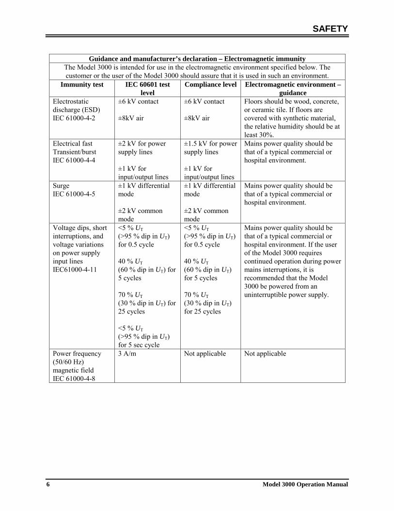
Guidance and manufacturer’s declaration – Electromagnetic immunity
The Model 3000 is intended for use in the electromagnetic environment specified below. The customer or the user of the Model 3000 should assure that it is used in such an environment.
Immunity test IEC 60601 test level
Compliance level Electromagnetic environment – guidance
Electrostatic discharge (ESD) IEC 61000-4-2
±6 kV contact ±8kV air
±6 kV contact ±8kV air
Floors should be wood, concrete, or ceramic tile. If floors are covered with synthetic material, the relative humidity should be at least 30%.
Electrical fast Transient/burst IEC 61000-4-4
±2 kV for power supply lines ±1 kV for input/output lines
±1.5 kV for power supply lines ±1 kV for input/output lines
Mains power quality should be that of a typical commercial or hospital environment.
Surge IEC 61000-4-5
±1 kV differential mode ±2 kV common mode
±1 kV differential mode ±2 kV common mode
Mains power quality should be that of a typical commercial or hospital environment.
Voltage dips, short interruptions, and voltage variations on power supply input lines IEC61000-4-11
<5 % UT (>95 % dip in UT) for 0.5 cycle 40 % UT (60 % dip in UT) for 5 cycles 70 % UT (30 % dip in UT) for 25 cycles <5 % UT (>95 % dip in UT) for 5 sec cycle
<5 % UT (>95 % dip in UT) for 0.5 cycle 40 % UT (60 % dip in UT) for 5 cycles 70 % UT (30 % dip in UT) for 25 cycles
Mains power quality should be that of a typical commercial or hospital environment. If the user of the Model 3000 requires continued operation during power mains interruptions, it is recommended that the Model 3000 be powered from an uninterruptible power supply.
Power frequency (50/60 Hz) magnetic field IEC 61000-4-8
3 A/m Not applicable Not applicable
SAFETY
Model 3000 Operation Manual 7
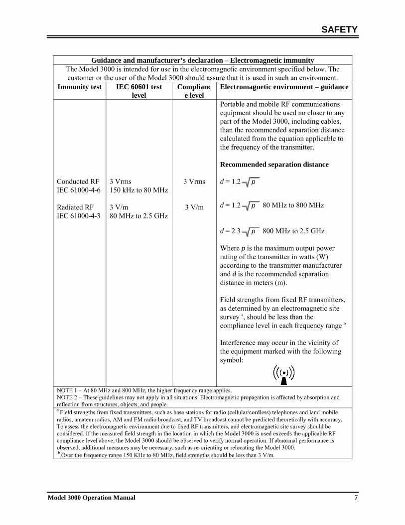
Guidance and manufacturer’s declaration – Electromagnetic immunity
The Model 3000 is intended for use in the electromagnetic environment specified below. The customer or the user of the Model 3000 should assure that it is used in such an environment.
Immunity test IEC 60601 test level
Compliance level
Electromagnetic environment – guidance
Conducted RF IEC 61000-4-6 Radiated RF IEC 61000-4-3
3 Vrms 150 kHz to 80 MHz 3 V/m 80 MHz to 2.5 GHz
3 Vrms
3 V/m
Portable and mobile RF communications equipment should be used no closer to any part of the Model 3000, including cables, than the recommended separation distance calculated from the equation applicable to the frequency of the transmitter. Recommended separation distance d = 1.2 p d = 1.2 p 80 MHz to 800 MHz d = 2.3 p 800 MHz to 2.5 GHz Where p is the maximum output power rating of the transmitter in watts (W) according to the transmitter manufacturer and d is the recommended separation distance in meters (m). Field strengths from fixed RF transmitters, as determined by an electromagnetic site survey a, should be less than the compliance level in each frequency range b Interference may occur in the vicinity of the equipment marked with the following symbol:
NOTE 1 – At 80 MHz and 800 MHz, the higher frequency range applies. NOTE 2 – These guidelines may not apply in all situations. Electromagnetic propagation is affected by absorption and reflection from structures, objects, and people. a Field strengths from fixed transmitters, such as base stations for radio (cellular/cordless) telephones and land mobile radios, amateur radios, AM and FM radio broadcast, and TV broadcast cannot be predicted theoretically with accuracy. To assess the electromagnetic environment due to fixed RF transmitters, and electromagnetic site survey should be considered. If the measured field strength in the location in which the Model 3000 is used exceeds the applicable RF compliance level above, the Model 3000 should be observed to verify normal operation. If abnormal performance is observed, additional measures may be necessary, such as re-orienting or relocating the Model 3000. b Over the frequency range 150 KHz to 80 MHz, field strengths should be less than 3 V/m.

SAFETY
8 Model 3000 Operation Manual
Description of Warning Labels Attention, consult ACCOMPANYING DOCUMENTS before attempting to change
power supply s election o r car ry o ut i nterconnections. E quipment co nnected s hould comply with IEC-60601-1 or IEC-950 with configuration to IEC-60601-1-1.
♥ Type CF applied part, Defibrillator proof.
Fuse type/rating. Output signal. _______ ON Input signal.
Stand By (STBY) ∼ Alternate Current (AC)
Protective earth (ground) Input/Output signal WEEE Compliance
Equipotential ground connector adjacent to this symbol.

MONITOR DESCRIPTION
Model 3000 Operation Manual 9
MONITOR DESCRIPTION The Model 3000 series Cardiac Trigger Monitor is an easy to use color monitor that displays a patient’s ECG waveform and heart rate. The ECG lead displayed can be selected from Leads I, II or III. In addition high and low heart rate alarm limits can be adjusted to bracket the patient’s heart rate so that a violation of these limits produces an audible and visual indication of the violation. The color display has a single trace, large Heart Rate numbers and alphanumeric characters for other data, alarm messages, menus and user information. The Model 3000 monitor is intended primarily for use on patients in applications requiring precision R-wave synchronization such as timed imaging studies. An optional integral recorder is available, set up of recorder functions are made through the monitor menus The Model 3000 series are available with different options; not all options are included in all monitors. The Model 3000 is suitable for use in presence of Electro-surgery. The Model 3000 is not intended for use with any other physiological monitoring unit. The Model 3000 is restricted to use on one patient at a time. The Model 3000 is not intended for home-care patient monitoring Classification (in accordance with IEC-60601-1) Protection against electric shock: Class 1. Degree of protection against electric shock: Type CF applied part. Defibrillator proof: ECG Degree of protection against harmful ingress of water: Ordinary equipment IPX0 per IEC-60529 Methods of Maintenance and Cleaning: See page 30 Degree of safety of application in the presence of a Equipment not suitable for use in the presence of a flammable anesthetic mixture with air or with oxygen flammable anesthetic mixture or nitrous oxide: Mode of operation: Continuous

MONITOR DESCRIPTION
Model 3000 Operation Manual 10
Controls and Indicators Basic Keys
When the monitor is plugged into an AC power source the ON switch, when pressed, provides power to the monitor’s electronic circuits.
The STBY switch, when pressed, disconnects power from the monitor’s electronic circuits. NOTE: To disconnect the monitor from the main power unplug the AC power cord.
Disables the audible and visual alarms for a two-minute period to allow the operator perform procedures that would otherwise set off the alarms. This avoids the problem of turning off the alarms and forgetting to turn them back on. Press this key again to return the alarms to normal before the two minutes have expired. Pressing ALARM PAUSE
key for 3 seconds will turn alarms off. Press ALARMS PAUSE key again to reactivate the alarms. Pressing ALARM PAUSE key will pause the alarms for 120 seconds (2 minutes).
Programmable Keys Displayed ab ove each p rogrammable k ey i s ei ther a m enu i tem o r a function. Pressing a programmable key will display other menu levels or activate an appropriate function. Menu functions are described in the Menu Structure section of this manual.
Programmable Keys
ECG Patient Cable Connector Alarm Pause
Key (Basic Key)
ON switch (Basic Key)
Stand By switch (Basic Key)
Recorder
Cardiac Trigger Monitor 3000
MONITOR DESCRIPTION
Model 3000 Operation Manual 11
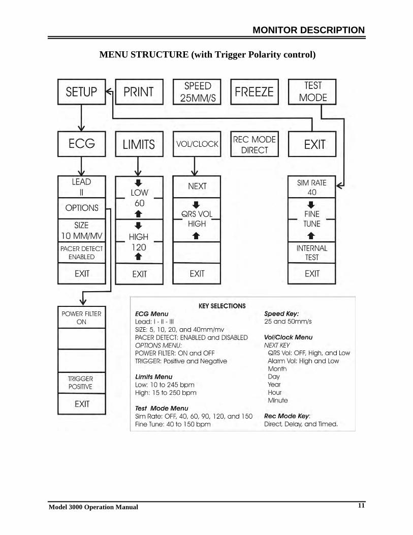
MENU STRUCTURE (with Trigger Polarity control)
MONITOR DESCRIPTION
Model 3000 Operation Manual 12
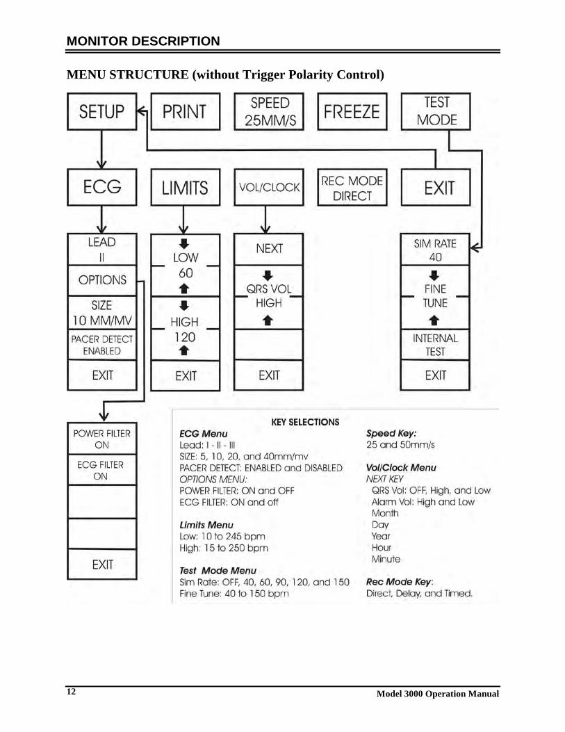
MENU STRUCTURE (without Trigger Polarity Control)

MONITOR DESCRIPTION
Model 3000 Operation Manual 13
Display HEART RATE: Displayed in beats per minute (bpm) on the upper part of the screen. SETUP: Selections made in the menu setup modes (alarm limits, lead selection, and filter on/off) are displayed in small characters at the upper left corner. ECG: Trace is displayed across the screen moving from left to right.
Normal Display Mode
Freeze Display Mode
Cardiac Trigger Monitor 3000
Cardiac Trigger Monitor 3000

MONITOR DESCRIPTION
Model 3000 Operation Manual 14
ALARMS: The following alarm indications are displayed in reverse video. Alarm indications appear on the center of the screen and flash once per second . ALARMS PAUSE message (PAUSE) is also displayed on the center of the screen and is displayed in red text. ALARMS OFF: The audible and visual alarms have been turned off. LEAD OFF: A lead has become disconnected. This alarm cannot be reset with the ALARM PAUSE key. HR HIGH: The high heart rate limit has been exceeded for four seconds. HR LOW: The low heart rate limit has been exceeded for four seconds. ASYSTOLE: The interval between heartbeats has exceeded six seconds. PAUSE: The alarms are paused for 120 seconds. WARNING: The monitor always powers on with the ALARMS paused for 30 seconds and then they are set to ON. Rear Panel The following are located on the rear panel. POWER INPUT: A receptacle for a standard ac power cord. NOTE: When the monitor is connected to another piece of equipment, always make sure that each piece of connected equipment has its own separate ground connection. Do not attempt to connect cables to these connectors without contacting your Biomedical Engineering Department. This is to ensure the connection co mplies w ith l eakage cu rrent r equirements o f o ne o f t he f ollowing ap plicable standards: UL2601-1, CAN/CSA C22.2 No 601.1-M90, IEC 60601-2-25, and CE-MDD 93/42/ECC. The maximum non-destructive voltage that may be applied to these connectors is 5V. SYNCHRONIZED OUTPUT: A BNC type connector for the output of the synch pulse indicating the timing of the peak of the R-wave. Limit to 100Hz bandwidth. PEQ GROUND: P otential E qualization - A gr ound connection t hat can b e u sed t o en sure t hat n o p otential differences can develop between this equipment and other electrical equipment. FUSE: Replace only with the same type and rating of fuse as indicated on the fuse rating label T.5A 250V (Metric 5x20mm). ECG X1000 (ECG X500 for GEMS Nuclear Medicine applications only) and SYNCHRONIZED OUTPUT: This i s a ¼ s tereo p hone j ack w ith an E CG an alog w aveform output on the tip , synch output on the r ing, a nd common on the sleeve. Limit to 100Hz bandwidth. AUXILIARY: A digital interface for device communication. This auxiliary output provides 5V and -8V with a maximum current of 20mA. LINE VOLTAGE SELECTOR: Switch to select the input voltage range of the device (100 to 230V~, 47 to 63 Hz.).

MONITOR DESCRIPTION
Model 3000 Operation Manual 15
The use of ACCESSORY equipment not complying with the equivalent safety requirements of this equipment may lead to a reduce level of safety of the resulting system. Consideration relating to the choice shall include:
• Use of the accessory in the PATIENT VICINITY • Evidence that the safety certification of the ACCESSORY has been performed in accordance to the
appropriate IEC 60601-1 and / or IEC 60601-1-1 harmonized national standard.
Fuse Ratings The fuses are located behind the cover of the power entry module. To replace the fuses, remove the cover and replace them only with same type and rating T.5A, 250V (Metric 5x20mm).
ECG X1000 and Synchronized
Output (ECG X500 for GEMS only)
BNC connector Synchronized
Output AUXILIARY Line Voltage
Selector
Power entry module
PEQ Ground
Fuses (Behind the
panel)

MONITOR SETUP
16 Model 3000 Operation Manual
MONITOR SETUP To Setup the Instrument for operation WARNING: Before this monitor is plugged into any power source verify visually that the line selector switch on the rear panel displays the appropriate voltage range for your location. For further instructions see “To change mains voltage” below. 1. Plug the ac line cord into a power source providing the proper voltage. 2. Press the ON switch at the left side of the front panel to turn power on. 3. Connect the patient cable to the ECG connector on the front panel. To Change Mains Voltage 1. Verify that the power cord is disconnected. 2. Locate the line voltage selector switch on the monitor rear panel. 3. If necessary move the selector switch to the appropriate voltage for your location (for assistance contact your
Maintenance Department). To set the Language Use the following procedure to change the language of the menu and messages. 1. Turn monitor off by pressing the STBY key. 2. Press and hold the fourth and fifth soft key (from left to right) while applying power to the monitor by pushing
the ON key. 3. Press the [LANGUAGE] key to set the desire language. The language choices are: English, Spanish, French,
German, Italian, Portuguese, and Swedish. 4. Turn monitor off by pressing the STBY key. To Set the Time, Date and Audio Use the following procedure to set the date and time. The time is indicated in the upper left corner of the display. 1. Press the [SETUP] key in the main menu. 2. Press the [VOL/CLOCK] key to access the Vol/Clock menu. 3. The first setting is for QRS VOL. Use the and keys to increase or decrease the QRS VOL setting. 4. Press [NEXT] to move to the ALARM VOL setting. Use the and keys to increase or decrease the
ALARM VOL setting. 5. Press [NEXT] to move to the MONTH setting. Use the and keys to increase or decrease the month
setting. 6. Press [NEXT] to move to the DAY setting. Use the and keys to increase or decrease the day setting. 7. Press [NEXT] to move to the YEAR setting. Use the and keys to increase or decrease the year setting. 8. Press [NEXT] to move to the HOUR setting. Use the and keys to increase or decrease the hour setting. 9. Press [NEXT] to move to the MINUTE setting. Use the and keys to increase or decrease the minute
setting. When all date, clock and audio settings are correct, select [EXIT] to enter the settings into the monitor’s memory.
MONITOR SETUP
Model 3000 Operation Manual 17
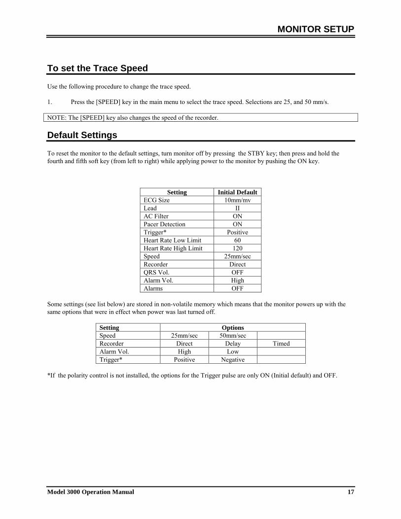
To set the Trace Speed Use the following procedure to change the trace speed. 1. Press the [SPEED] key in the main menu to select the trace speed. Selections are 25, and 50 mm/s. NOTE: The [SPEED] key also changes the speed of the recorder. Default Settings To reset the monitor to the default settings, turn monitor off by pressing the STBY key; then press and hold the fourth and fifth soft key (from left to right) while applying power to the monitor by pushing the ON key.
Setting Initial Default ECG Size 10mm/mv Lead II AC Filter ON Pacer Detection ON Trigger* Positive Heart Rate Low Limit 60 Heart Rate High Limit 120 Speed 25mm/sec Recorder Direct QRS Vol. OFF Alarm Vol. High Alarms OFF
Some settings (see list below) are stored in non-volatile memory which means that the monitor powers up with the same options that were in effect when power was last turned off.
Setting Options Speed 25mm/sec 50mm/sec Recorder Direct Delay Timed Alarm Vol. High Low Trigger* Positive Negative
*If the polarity control is not installed, the options for the Trigger pulse are only ON (Initial default) and OFF.

ALARM MESSAGES
18 Model 3000 Operation Manual
ALARM MESSAGES The following alarm message is displayed in reverse video of white letters on a red back ground. ALARMS OFF :All audible and visual alarms have been turned off:
To turn all audible and visual ALARMS ON press key once.
To turn all audible and visual ALARMS OFF press and hold key for three seconds. The following alarm messages are displayed in flashing reverse video. White letters on a red back ground flashing at a rate of once every second with an audio frequency of 4KHz.
Press key to reset all alarms except LEAD OFF. The following describes each of the alarm indications. HR HIGH: The high heart rate alarm limit has been exceeded for four seconds. HR LOW: The low heart rate alarm limit has been exceeded for four seconds. ASYSTOLE: The interval between heartbeats has exceeded six seconds. LEAD OFF: A lead has become disconnected or the electrode offset potential has exceeded ≥0.5 V
This alarm cannot be reset with the key . The following alarm message is displayed red letters: PAUSE:All audible and visual alarms are turned off for 120 seconds.
To activate alarm PAUSE press key once.
To cancel alarm PAUSE wait for 120 second PAUSE cycle to expire or press key again.
WARNING: The monitor always powers on with the ALARMS paused for 30 seconds and then they are set to ON. Low Signal Message If the amplitude of the ECG signal is between 300µV and 500µV (3mm to 5mm at size 10mm/mv) for a period of eight seconds a LOW SIGNAL message will be displayed in yellow below the ECG waveform (see ECG monitoring section). Pacer detection Message The message “PACER DETECT DISABLED” will appear if the pacer detection circuit is disabled through the ECG menu.
ECG MONITORING
Model 3000 Operation Manual 19
ECG MONITORING
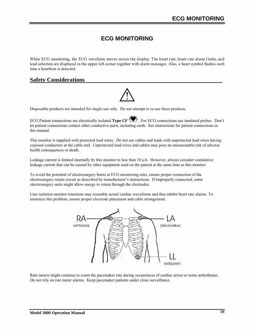
When ECG monitoring, the ECG waveform moves across the d isplay. The heart rate, heart rate alarm l imits, and lead selection are displayed in the upper left corner together with alarm messages. Also, a heart symbol flashes each time a heartbeat is detected. Safety Considerations
Disposable products are intended for single-use only. Do not attempt to re-use these products.
ECG Patient connections are electrically isolated Type CF . For ECG connections use insulated probes. Don’t let patient connections contact other conductive parts, including earth. See instructions for patient connections in this manual. This monitor is supplied with protected lead wires. Do not use cables and leads with unprotected lead wires having exposed conductors at the cable end. Unprotected lead wires and cables may pose an unreasonable risk of adverse health consequences or death. Leakage current is limited internally by this monitor to less than 10 μA. However, always consider cumulative leakage current that can be caused by other equipment used on the patient at the same time as this monitor. To avoid the potential of electrosurgery burns at ECG monitoring sites, ensure proper connection of the electrosurgery return circuit as described by manufacturer’s instructions. If improperly connected, some electrosurgery units might allow energy to return through the electrodes. Line isolation monitor transients may resemble actual cardiac waveforms and thus inhibit heart rate alarms. To minimize this problem, ensure proper electrode placement and cable arrangement.
Rate meters might continue to count the pacemaker rate during occurrences of cardiac arrest or some arrhythmias. Do not rely on rate meter alarms. Keep pacemaker patients under close surveillance.
ECG MONITORING
20 Model 3000 Operation Manual
Patient Connections To en sure co mpliance w ith b oth s afety an d p erformance s pecifications, u se t he p atient cab les s upplied b y I vy Biomedical Systems (see Accessories). Other cables might not produce reliable results. Use only high quality pre gel silver/silver-chloride electrodes or equivalent. Use the following procedure for ECG monitoring: 1. Before applying the electrodes, use Nuprep gel or a gauze pad to gently clean the area where the electrodes will
be applied. 2. Connect the patient cable to the monitor's front panel ECG input. 3. Connect the leads to the patient cable. 4. Attach the leads to the electrodes. 5. Use t he p rocedures d escribed in th e f ollowing s ections f or a larm limit settings, lead selection, amplitude
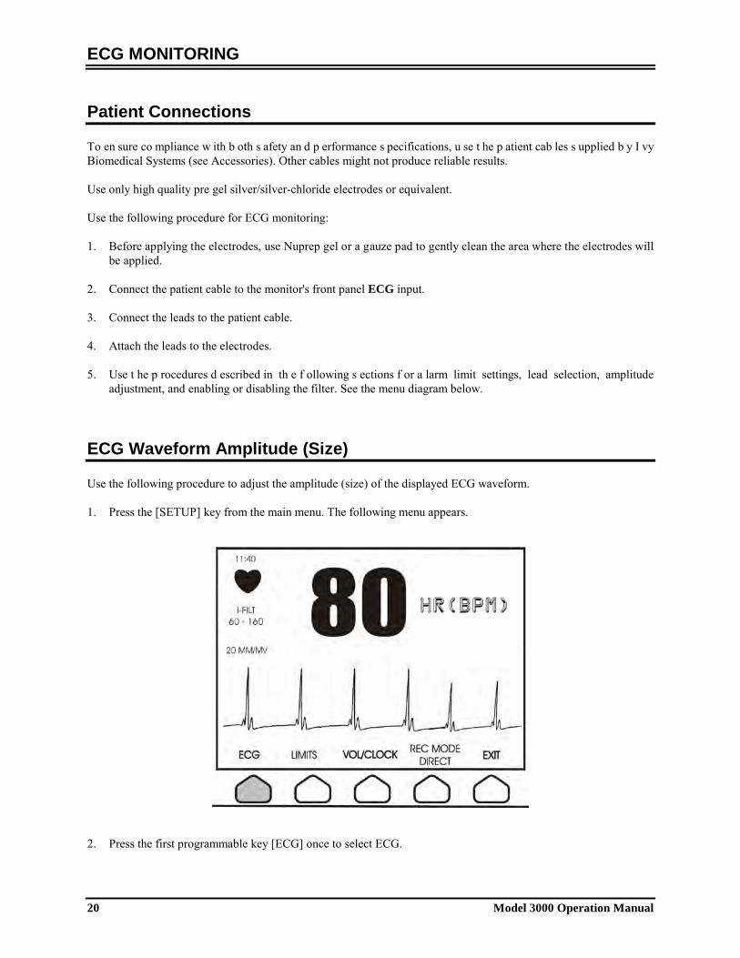
adjustment, and enabling or disabling the filter. See the menu diagram below. ECG Waveform Amplitude (Size) Use the following procedure to adjust the amplitude (size) of the displayed ECG waveform. 1. Press the [SETUP] key from the main menu. The following menu appears.
2. Press the first programmable key [ECG] once to select ECG.
HR(BPM)
ECG MONITORING
Model 3000 Operation Manual 21
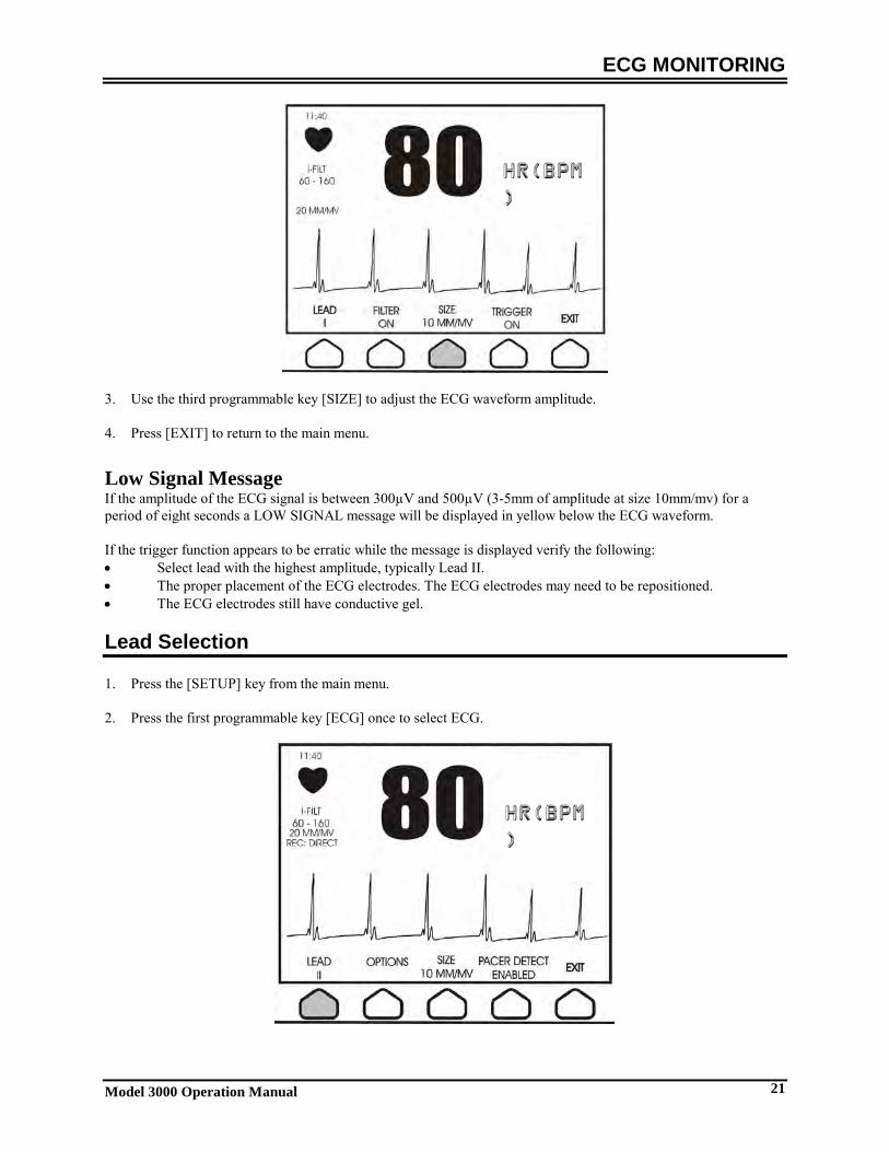
3. Use the third programmable key [SIZE] to adjust the ECG waveform amplitude. 4. Press [EXIT] to return to the main menu. Low Signal Message If the amplitude of the ECG signal is between 300µV and 500µV (3-5mm of amplitude at size 10mm/mv) for a period of eight seconds a LOW SIGNAL message will be displayed in yellow below the ECG waveform. If the trigger function appears to be erratic while the message is displayed verify the following: • Select lead with the highest amplitude, typically Lead II. • The proper placement of the ECG electrodes. The ECG electrodes may need to be repositioned. • The ECG electrodes still have conductive gel. Lead Selection 1. Press the [SETUP] key from the main menu. 2. Press the first programmable key [ECG] once to select ECG.
HR(BPM)
HR(BPM)
ECG MONITORING
22 Model 3000 Operation Manual
3. Select [LEAD] to change the lead selection. The current lead selection is shown above the alarm limits in the upper left portion of the display. Available lead selections are Lead I, Lead II, or Lead III.
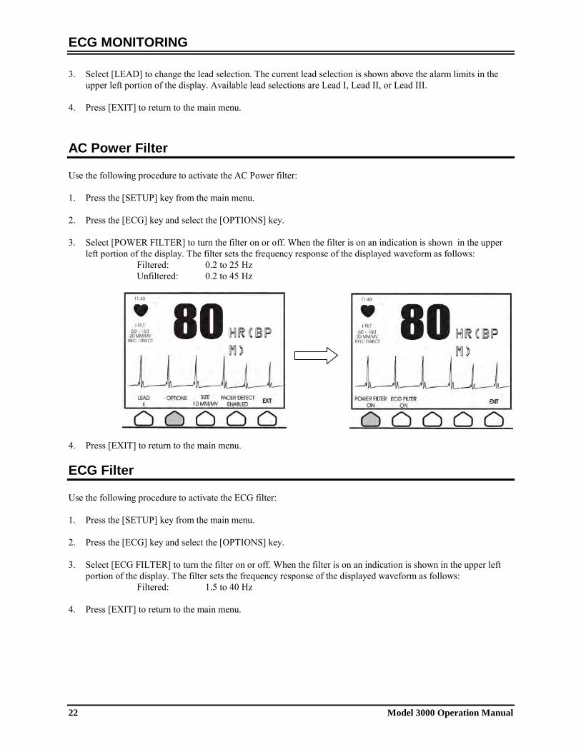
4. Press [EXIT] to return to the main menu. AC Power Filter Use the following procedure to activate the AC Power filter: 1. Press the [SETUP] key from the main menu. 2. Press the [ECG] key and select the [OPTIONS] key. 3. Select [POWER FILTER] to turn the filter on or off. When the filter is on an indication is shown in the upper
left portion of the display. The filter sets the frequency response of the displayed waveform as follows: Filtered: 0.2 to 25 Hz Unfiltered: 0.2 to 45 Hz
4. Press [EXIT] to return to the main menu. ECG Filter Use the following procedure to activate the ECG filter: 1. Press the [SETUP] key from the main menu. 2. Press the [ECG] key and select the [OPTIONS] key. 3. Select [ECG FILTER] to turn the filter on or off. When the filter is on an indication is shown in the upper left
portion of the display. The filter sets the frequency response of the displayed waveform as follows: Filtered: 1.5 to 40 Hz
4. Press [EXIT] to return to the main menu.
HR(BPM)
HR(BPM)

ECG MONITORING
Model 3000 Operation Manual 23
Alarm Limits 1. Press the [SETUP] key from the main menu. The following menu appears.
2. Press the programmable key [LIMITS] to enter the Alarm Limits menu.
3. Use the programmable keys to set the high and low heart rate limits. Increases high HR limit Decreases high HR limit
Increases low HR limit Decreases low HR limit
Each time you press a key, the corresponding limit changes by 5 bpm. The current HR limits are always shown in the upper left portion of the display. 4. Press [EXIT] to return to the main menu.
Alarm Type Default Limit Heart Rate Low 60 Heart Rate High 120
Pacemaker Follow the next procedure to activate or deactivate the pacemaker detection function: 1. Press the [SETUP] key from the main menu.
2. Press the [ECG] key and then select the [PACER DETECT] key to toggle between pacer detection enabled or
disabled. When a pacemaker has been detected, a P will start flashing in the heart symbol. The message “PACER DETECT DISABLED” will appear if the pacer detection circuit is not active. WARNING: Rate meters might continue to count the pacemaker rate during occurrences of cardiac arrest or some arrhythmias. Do not rely on heart rate alarms. Keep pacemaker patients under close surveillance.
HR(BPM)

RECORDER OPERATION
24 Model 3000 Operation Manual
RECORDER OPERATION
(Optional) Changing Paper Replace the roll of thermal paper as follows. (Recorder paper is Ivy P/N: 590035) 1. Press the paper eject button to open the door at the front of the recorder.
If the door does not open completely, pull it toward you until it is completely open. 2. Reach in and remove the spent paper core by pulling it gently toward you. 3. Place a new paper roll between the two round tabs of the paper holder. 4. Pull some paper from the roll. Make sure the sensitive (shiny) side of the paper faces the print head. The
shiny side of the paper normally faces inside the roll. 5. Align the paper with the pinch roller on the door.
Press Here
Print Head
Pinch Roller
Pinch Roller
RECORDER OPERATION
Model 3000 Operation Manual 25
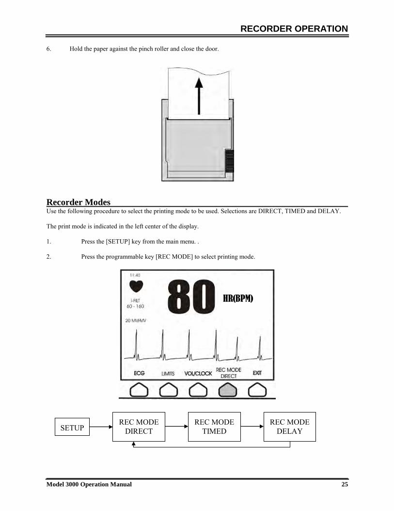
6. Hold the paper against the pinch roller and close the door.
Recorder Modes Use the following procedure to select the printing mode to be used. Selections are DIRECT, TIMED and DELAY. The print mode is indicated in the left center of the display. 1. Press the [SETUP] key from the main menu. . 2. Press the programmable key [REC MODE] to select printing mode.
HR(BPM)
SETUP REC MODE
DIRECT REC MODE
TIMED REC MODE
DELAY
RECORDER OPERATION
26 Model 3000 Operation Manual
Direct To print in direct, press the [PRINT] key. Press [PRINT] again to stop printing. The plot is preceded by a header which contains all parameter readings and the time/date. The speed of the plot and vertical resolution are the same as the display. The plot is labeled with the speed of the plot in mm/s, the recorder mode, and the parameters. Timed TIMED mode starts by pressing [PRINT] and prints for 30 seconds. Delay Delay mode plots 30 or 40 seconds of ECG waveform after the occurrence of an alarm condition or if print button is pushed depending on the speed selected:
15 seconds before and 15 seconds after at 50mm/s 20 seconds before and 20 seconds after at 25mm/s
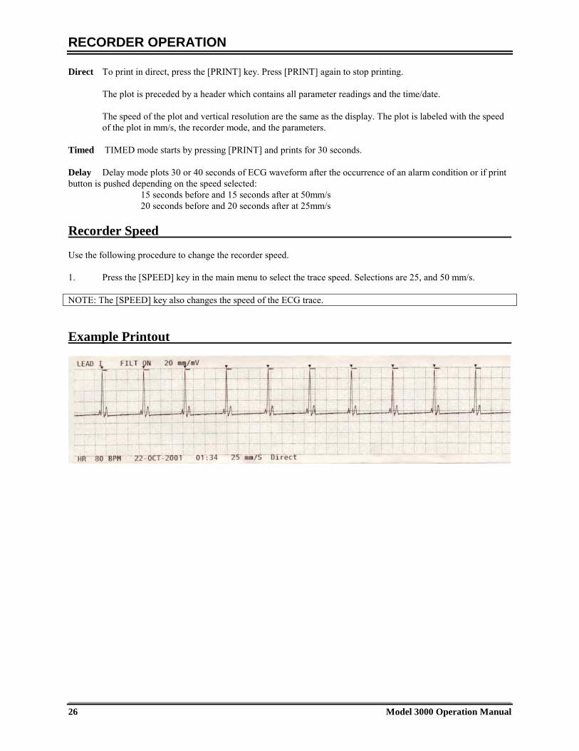
Recorder Speed Use the following procedure to change the recorder speed. 1. Press the [SPEED] key in the main menu to select the trace speed. Selections are 25, and 50 mm/s. NOTE: The [SPEED] key also changes the speed of the ECG trace. Example Printout

SYNCHRONIZED OUTPUT
Model 3000 Operation Manual 27
SYNCHRONIZED OUTPUT (Trigger)
The Synch Pulse The ECG Synchronized Output produces a trigger pulse starting at the peak of each R-wave , which is available on the SYNCHRONIZED OUTPUT BNC connector and on the ECG X1000 (ECGX500 for GEMS Nuclear Medicine Applications) output connector, ring on the ¼” stereo jack, on the rear panel of the monitor. Connect the Synchronized Output from the monitor to the device being synchronized. The following shows the timing of the trigger pulse compared to the ECG waveform.
Trigger- Mark Display The Synchronized trigger output is always active. A portion of the ECG waveform corresponding to the timing of the synch pulse is highlighted in red. If the trigger function appears to be erratic verify the following: • Select lead with the highest amplitude, typically Lead II. • The proper placement of the ECG electrodes. The ECG electrodes may need to be repositioned. • The ECG electrodes still have conductive gel.
Trigger pulse width options 1ms 50ms 100ms 150ms
GEMS ISRAEL ELGEMS
ELSCINT MARCONI
PHILIPS SIEMENS
SMV TOSHIBA
ADAC IMATRON
IVY
Trigger pulse amplitude options
0V to 5V Positive Edge
5V to 0 V Negative Edge
-11V to +11V 0V to 4.2V
ADAC ELSCINT IMATRON
IVY MARCONI
PHILIPS SIEMENS
SMV TOSHIBA
ELSCINT PHILIPS
SIEMENS
ELGEMS GEMS ISRAEL
SPECIAL ORDER HIGH CURRENT
OPTION
SYNCHRONIZED OUTPUT
28 Model 3000 Operation Manual
Trigger Polarity Control (available for some OEM customers) The trigger polarity control allows the user to change the polarity of the trigger pulse to either positive edge (0V to 5V) or negative edge (5V to 0V). Use the following procedure to set the polarity of the trigger pulse: 1. Press the [SETUP] key in the main menu. 2. Press the [ECG] key to access the ECG menu. 3. Press the [OPTIONS] key. 4. Press the [TRIGGER] key to toggle through the different trigger options (TRIGGER POSITIVE and
TRIGGER NEGATIVE). 5. Press [EXIT] to return to the main menu. NOTE:
1. Each time the monitor power is turned on a flashing message will be displayed (bottom left corner of the display) for one minute to indicate the status of the trigger pulse.
2. Each time the trigger pulse polarity is changed, a flashing message will be displayed (bottom left corner of the display) for one minute to indicate the status of the trigger pulse.

MONITOR TESTING
Model 3000 Operation Manual 29
MONITOR TESTING Press t he [ TEST] key to te st th e in ternal f unctions o f th e m onitor. Y ou s hould d o th is e ach tim e y ou b egin monitoring a patient. The [TEST] function generates a 1 mV pulse at 70 bpm, causing a waveform and a 70 bpm indication on the display and a signal at the rear panel connector. If these indications are not present, contact qualified service personnel. To test the visual and audio alarms turn on the monitor. Make sure the ALARMS OFF message is not present in the
center portion of the display. If the alarms are off press the key. Unplug the patient cable. Check that the LEAD OFF messages is displayed on the ECG channel and the audio alarm is on. While pressing the TEST key check for the following to happen: 1) LEAD OFF message disappear, and 2) Monitor starts counting QRS. Stop
pressing the TEST key and press for three seconds, the message PAUSE and the timer should be displayed on the display, all audio and visual alarms should be off Under normal operation, no internal adjustment or r ecalibration is required. Safety te sts and in ternal a djustments should be done by qualified personnel only. Safety checks should be performed at regular intervals or in accordance with local or governmental regulations. In the event that internal adjustment or recalibration is necessary, refer to the Operation and Service Manual for this equipment. Note: If no display is visible on the monitor, the monitor is inoperable, contact qualified personal. When the patients ECG signal amplitude input is >0.5 V, an inoperable condition is indicated by a flashing LEAD OFF indicator on the display. ECG Simulator (Optional) The model 3000 can have an optional integrated simulator that is used to verify the integrity of the patient cable, lead wires and electronic circuits involved in the processing of the patient’s ECG signal. The simulator terminals are located in the right side panel of the monitor and have three color coded labels for easy identification. The terminals are used to attach the lead wires. The simulator generates a simulated ECG waveform and heart rate within 40-150bpm range (user selectable). When the simulator is on, a message “SIMULATOR ON” is displayed in the center of the screen below the ECG trace. ECG Simulator operation To turn the simulator on and set the heart rate, follow the procedure below: 1. Press the [TEST MODE] key located in the main menu to access the simulator mode menu. 2. Press the key [SIM RATE] to turn the simulator on and toggle through the heart rate options. 3. Press the keys [ ↑ FINE TUNE ↓ ] to change the heart rate in increments of one bpm. 4. Press [EXIT] to exit the test mode menu.
NOTE: When the simulator is on, a message “SIMULATOR ON” is displayed in the center of the screen below the ECG trace.

MAINTENANCE AND CLEANING
30 Model 3000 Operation Manual
MAINTENANCE AND CLEANING The Monitor When necessary, clean the exterior surfaces of the monitor with a cloth or swab dampened with a warm water and mild detergent solution. Do not allow liquids to enter the interior of the instrument. CAUTION:
• Do not autoclave, pressure sterilize, or gas sterilize the monitor.
• Do not soak or immerse in any liquid.
• Use cleaning solution sparingly. Excessive solution can flow into the monitor and cause damage to internal components.
• Do not touch, press or rub the display and covers with abrasive cleaning compounds, instruments, brushes,
rough surface materials, or bring them into contact with anything that could scratch the display or the covers.
• Do not use petroleum based or acetones solutions, or other harsh solvents, to clean the monitor.
Patient Cables Do not autoclave the patient cables. Wipe the cables using a mild detergent solution. Never submerge the cables in any liquid or allow liquids to enter the electrical connections. Preventive Maintenance ECG Check before connecting the monitor to a new patient that:
• Cables and Leads are clean and intact. • The LEAD OFF message is displayed when the patient cable is connected, but the patient leads are not
connected. Connecting the patient leads together should make the message disappear. • The BNC Interconnect cable is clean and intact.
NOTE: There are no user serviceable items contained in the model 3000.

ACCESSORIES
Model 3000 Operation Manual 31
ACCESSORIES ECG 3 Lead Patient Cable 590406 Set of 3 leads (Colors: Red, Black, and White) 590407 Low noise 3 Lead ECG Patient Cable (For CT Scanner customers only) 590317 Set of three radiotranslucent lead wires (For CT Scanner customers only) 590318 BNC Interconnect Cable Assembly (8 ft long) 1564-01-10 Box of 10 rolls of recorder paper 590035 Fuse, ½ ASB (5x20mm) 100-230V 290017 Cord set, Hospital Grade 610007 Jumper Cord 610012 ECG electrodes (Box of 30) 590342 Disposal Disposal of devices or consumables must be done in accordance with local, state, and federal laws and regulations. WEEE Directive 2002/96/EC.- Do not dispose of WEEE products in general waste. At the end of life of product contact IVY Biomedical Systems, Inc. customer service for return instructions.
To order accessories please contact customer service: • Tele: (800) 247-4614 ext 106 • Tele: (203) 481-4183 ext 106 • Fax: (203) 481-8734 • E-mail: [email protected]
SPECIFICATIONS
32 Model 3000 Operation Manual
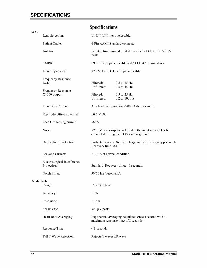
Specifications ECG Lead Selection: LI, LII, LIII menu selectable. Patient Cable: 6-Pin AAMI Standard connector
Isolation: Isolated from ground related circuits by >4 kV rms, 5.5 kV peak
CMRR: ≥90 dB with patient cable and 51 kΩ/47 nF imbalance Input Impedance: ≥20 MΩ at 10 Hz with patient cable Frequency Response LCD: Filtered: 0.5 to 25 Hz Unfiltered: 0.5 to 45 Hz Frequency Response X1000 output: Filtered: 0.5 to 25 Hz Unfiltered: 0.2 to 100 Hz Input Bias Current: Any lead configuration <200 nA dc maximum Electrode Offset Potential: ±0.5 V DC Lead Off sensing current: 56nA
Noise: <20 µV peak-to-peak, referred to the input with all leads connected through 51 kΩ/47 nF to ground
Defibrillator Protection: Protected against 360 J discharge and electrosurgery potentials Recovery time <6s Leakage Current: <10 µA at normal condition Electrosurgical Interference Protection: Standard. Recovery time: <6 seconds. Notch Filter: 50/60 Hz (automatic). Cardiotach Range: 15 to 300 bpm Accuracy: ±1% Resolution: 1 bpm Sensitivity: 300 µV peak
Heart Rate Averaging: Exponential averaging calculated once a second with a maximum response time of 8 seconds.
Response Time: ≤ 8 seconds Tall T Wave Rejection: Rejects T waves ≤R wave
SPECIFICATIONS
Model 3000 Operation Manual 33
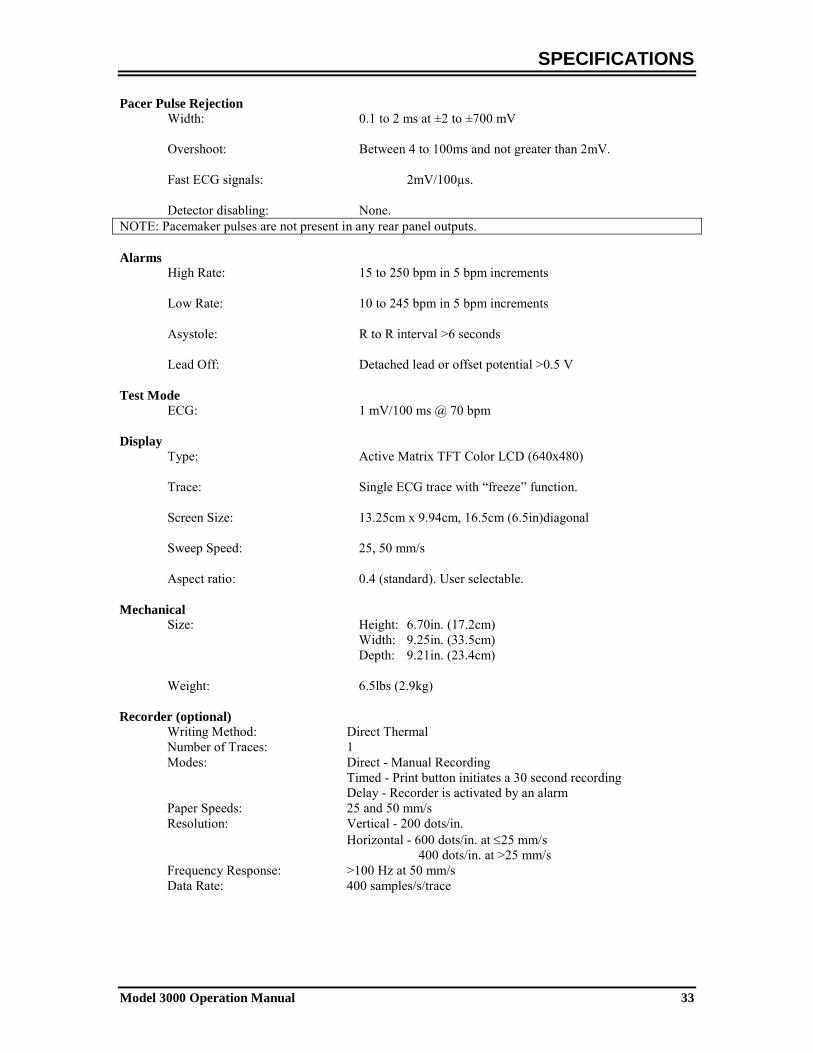
Pacer Pulse Rejection Width: 0.1 to 2 ms at ±2 to ±700 mV
Overshoot: Between 4 to 100ms and not greater than 2mV.
Fast ECG signals: 2mV/100µs. Detector disabling: None.
NOTE: Pacemaker pulses are not present in any rear panel outputs. Alarms High Rate: 15 to 250 bpm in 5 bpm increments Low Rate: 10 to 245 bpm in 5 bpm increments Asystole: R to R interval >6 seconds Lead Off: Detached lead or offset potential >0.5 V Test Mode
ECG: 1 mV/100 ms @ 70 bpm Display Type: Active Matrix TFT Color LCD (640x480) Trace: Single ECG trace with “freeze” function. Screen Size: 13.25cm x 9.94cm, 16.5cm (6.5in)diagonal Sweep Speed: 25, 50 mm/s Aspect ratio: 0.4 (standard). User selectable. Mechanical Size: Height: 6.70in. (17.2cm) Width: 9.25in. (33.5cm) Depth: 9.21in. (23.4cm) Weight: 6.5lbs (2.9kg) Recorder (optional) Writing Method: Direct Thermal Number of Traces: 1 Modes: Direct - Manual Recording Timed - Print button initiates a 30 second recording Delay - Recorder is activated by an alarm Paper Speeds: 25 and 50 mm/s Resolution: Vertical - 200 dots/in. Horizontal - 600 dots/in. at ≤25 mm/s 400 dots/in. at >25 mm/s Frequency Response: >100 Hz at 50 mm/s Data Rate: 400 samples/s/trace

SPECIFICATIONS
34 Model 3000 Operation Manual
Synchronized Output (Trigger) Phase Delay from Electrode Leads to Trigger Output: < 3 ms R to R Trigger Accuracy: ±50µs typical @ 1 mV input Pulse width: 1 to 150ms (standard 150ms) Pulse amplitude: 0 to 5V, 5 to 0V, -11 to 11V Output Impedance: <100 Ω
Sensitivity and Threshold Adjustment: Fully Automatic Polarity control: Positive edge or Negative edge. Output connectors: ECG X1000 (ECG X500 for GEMS) – Ring BNC connector RS232 Real Time Clock Resolution: 1 minute Display: 24 hours Power Requirement: The real time clock keeps time if the monitor has power or not.
The clock is powered by a dedicated battery whose life is minimum 4 years at a temperature of 25oC
Environmental Operating Temperature Range: 5°C to 35°C Storage Temperature Range: -20°C to 49°C Relative Humidity: 0-90% non-condensing Atmospheric Pressure: 500-1060 mbar Power Requirements
Voltage Input: 100 to 230V~ Line Frequency: 47 to 63 Hz Fuses Type and Rating: T.5A, 250V (Metric 5x20mm)
Maximum ac Power Consumption: 35 VA Regulatory
Unit meets or exceeds the specifications for the AAMI Cardiac Monitor Standard EC-13, UL2601-1, CAN/CSA C22.2 No 601.1-M90, CDN MDR (CMDCAS), IEC 60601-2-25, IEC 60601-2-27, MDD.93/42/EEC, CE 0143, ISO 13485:1996, and FDA/CGMP.