model 15-bc200~15-bc299 hp pavilion notebook pc · hp pavilion notebook pc model 15-bc200~15-bc299...
TRANSCRIPT

HP Pavilion Notebook PCModel 15-bc200~15-bc299
Maintenance and Service GuideIMPORTANT! This document is intended for HP authorized service providers only.

© Copyright 2016 HP Development Company, L.P.
NVIDIA and Quadro are trademarks and/or registered trademarks of NVIDIA Corporation in the U.S. and other countries. Red Hat Enterprise Linux is a registered trademark of Red Hat, Inc. in the United States and other countries. Bluetooth is a trademark owned by its proprietor and used by HP Inc. under license. Intel, Pentium, and Core are trademarks of Intel Corporation in the U.S. and other countries. Windows is either a registered trademark or trademark of Microsoft Corporation in the United States and/or other countries.
Product notice
This guide describes features that are common to most models. Some features may not be available on your computer.
Not all features are available in all editions of Windows 8. This computer may require upgraded and/or separately purchased hardware, drivers and/or software to take full advantage of Windows 8 functionality. See http://www.microsoft.com for details.
The information contained herein is subject to change without notice. The only warranties for HP products and services are set forth in the express warranty statements accompanying such products and services. Nothing herein should be construed as constituting an additional warranty. HP shall not be liable for technical or editorial errors or omissions contained herein.
Second Edition: December 2016
First Edition: April 2016
Document Part Number: 854539-002

Safety warning notice
WARNING! To reduce the possibility of heat-related injuries or of overheating the device, do not place the device directly on your lap or obstruct the device air vents. Use the device only on a hard, flat surface. Do not allow another hard surface, such as an adjoining optional printer, or a soft surface, such as pillows or rugs or clothing, to block airflow. Also, do not allow the AC adapter to contact the skin or a soft surface, such as pillows or rugs or clothing, during operation. The device and the AC adapter comply with the user-accessible surface temperature limits defined by the International Standard for Safety of Information Technology Equipment (IEC 60950-1).
iii

iv Safety warning notice

Table of contents
1 Product description ....................................................................................................................................... 1
2 External component identification .................................................................................................................. 5
Right side ............................................................................................................................................................... 5
Left side ................................................................................................................................................................. 6
Display .................................................................................................................................................................... 7
Top .......................................................................................................................................................................... 8
TouchPad ............................................................................................................................................. 8
Lights ................................................................................................................................................... 9
Button and speakers ......................................................................................................................... 10
Keys ................................................................................................................................................... 11
Using the action keys ........................................................................................................................ 11
Bottom ................................................................................................................................................................. 12
Rear ...................................................................................................................................................................... 14
Locating system information .............................................................................................................................. 14
3 Illustrated parts catalog .............................................................................................................................. 16
Computer major components .............................................................................................................................. 16
Display assembly subcomponents ...................................................................................................................... 19
Miscellaneous parts ............................................................................................................................................. 20
4 Removal and replacement procedures preliminary requirements .................................................................... 22
Tools required ...................................................................................................................................................... 22
Service considerations ......................................................................................................................................... 22
Plastic parts ....................................................................................................................................... 22
Cables and connectors ...................................................................................................................... 23
Drive handling ................................................................................................................................... 23
Grounding guidelines ........................................................................................................................................... 24
Electrostatic discharge damage ........................................................................................................ 24
Packaging and transporting guidelines .......................................................................... 25
Workstation guidelines ................................................................................................... 25
Equipment guidelines ..................................................................................................... 26
5 Removal and replacement procedures for authorized service provider parts .................................................... 27
Component replacement procedures .................................................................................................................. 27
Base enclosure .................................................................................................................................. 27
v

Display assembly ............................................................................................................................... 29
Hard drive .......................................................................................................................................... 31
SSD (M.2) ........................................................................................................................................... 33
Memory .............................................................................................................................................. 34
WLAN module .................................................................................................................................... 37
Battery ............................................................................................................................................... 39
USB board .......................................................................................................................................... 42
Power button board .......................................................................................................................... 43
Fan ..................................................................................................................................................... 45
Heat sink for discrete graphics memory ........................................................................................... 46
Heat sink for CPU and graphics ......................................................................................................... 48
Speakers ............................................................................................................................................ 51
System board .................................................................................................................................... 53
RTC battery ........................................................................................................................................ 55
Power connector ............................................................................................................................... 56
TouchPad ........................................................................................................................................... 58
Display panel ..................................................................................................................................... 61
Webcam ............................................................................................................................................. 67
6 Using HP PC Hardware Diagnostics (UEFI) ....................................................................................................... 69
Downloading HP PC Hardware Diagnostics (UEFI) to a USB device .................................................................... 69
7 Backing up, restoring, and recovering ........................................................................................................... 71
Creating recovery media and backups ................................................................................................................ 71
Creating HP Recovery media (select products only) ......................................................................... 71
Using Windows tools ........................................................................................................................................... 72
Restore and recovery ........................................................................................................................................... 73
Recovering using HP Recovery Manager ........................................................................................... 73
What you need to know before you get started ............................................................. 73
Using the HP Recovery partition (select products only) ................................................. 74
Using HP Recovery media to recover .............................................................................. 74
Changing the computer boot order ................................................................................ 75
Removing the HP Recovery partition (select products only) ......................................... 76
8 Specifications .............................................................................................................................................. 77
Computer specifications ...................................................................................................................................... 77
39.62 cm (15.6-in) display specifications ........................................................................................................... 78
Hard drive specifications ..................................................................................................................................... 78
Solid-state drive specifications ........................................................................................................................... 79
vi

9 Power cord set requirements ........................................................................................................................ 80
Requirements for all countries ............................................................................................................................ 80
Requirements for specific countries and regions ................................................................................................ 80
10 Recycling .................................................................................................................................................. 82
Index ............................................................................................................................................................. 83
vii

viii

1 Product description
Category Description
Product Name HP Pavilion Notebook PC
Processors Intel Core™ i7-7700 HQ (2.8GHz, turbo up to 3.8 GHz), 2400 MHz/6 MB L3, Quad, TDP 45W, cTDP 35 W
Intel Core i5-7300 HQ (2.5 GHz, turbo up to 3.5 GHz), 2400 MHz/6 MB L3, Quad, TDP 45W, cTDP 35 W
Chipset Intel HM175
Graphics Internal graphics:
Intel HD Graphics 630
Hybrid graphics:
Nvidia N17 P-G0 (GeForce GTX 1050M) with up to 2048 MB of dedicated video memory (12 8Mx32 GDDR5 x 4 PCs, 1.5V/7Gbps)
Nvidia N17P-G0 (GeForce GTX 1050M) with up to 4096MB of dedicated video memory (256Mx32 GDDR5 x 4 PCs, 1.5V/7Gbps)
Support HD Decode, DX12, and HDMI
Support Optimus
Support GPS (GPU Performance Scaling)
Panel 16:9 Ultra Wide Aspect Ratio
15.6" FHD WLED AntiGlare (1920x1080) slim-flat (3.2mm) UWVA, eDP
15.6" FHD WLED AntiGlare (1920x1080) slim-flat (3.2mm) UWVA, eDP
Touch solution with flush glass, multitouch enabled
Memory Two SODIMM slots - customer non-accessible/non-upgradeable
DDR4-2400 Dual Channel Support
Supports up to 16GB max system memory
4096MB (4096MB x 1)
6144MB (2048MB x 1 + 4096MB x 1)
8192MB (4096MB x 2)
8192MB (8192MB x 1)
12288MB (8192MB +4096MB)
16384MB (8192MB x 2)
Hard drive Supports all 7mm/9.5mm, SATA 2.5" HDDs
Support M.2 SATA Storage
Accelerometer / HDD protection support
Single HDD configurations
1TB (7200) 9.5mm
2 TB (5400) 9.5mm
1

Category Description
PCIe NVMe TLC M.2 SSD
256 GB
512 GB
HDD+SSD configurations
1TB (7200) 9.5mm HDD + 256GB PCIe NVMe TLC M.2 SSD
1TB (7200) 9.5mm HDD + 128GB M.2 SATA-3 SSD (Value)
2TB (5400) 9.5mm HDD + 128 GB M.2 SATA-3 SSD (Value)
Optical drive (External USB)
9.5 mm tray load - SATA - External USB ODD (Aluminium material)
DVD+/-RW Double-Layer SuperMulti
Camera and Microphone
HP TrueVision HD:
HP Wide Vision HD Camera - indicator LED, USB2.0, BSI sensor, f2.0, 88° WFOV
720p by 30 frames per second
Dual array Digital Microphones w/ appropriate software - beam forming, echo cancellation, noise suppression
Enable HP Noise Cancellation
Audio B&O Play
Support HP Audio Boost
Dual Speakers
Ethernet Integrated 10/100/1000 NIC
Wireless Integrated Wireless options with dual antennas (M.2/PCIe):
Intel Dual Band Wireless-AC 7265 802.11 ac 2x2 WiFi + BT 4.2 Combo Adapter (non vPRO)
Intel WiDi support
Compatible with Miracast-certified devices
External media cards HP Multi-Format Digital Media Card Reader
Support SD/SDHC/SDXC
Push-Push Insertion/Removal
Internal card expansion
One M.2 slot for WLAN
One M.2 slot for SSD
Ports Hot Plug / Unplug and auto detect for correct output to wide-aspect vs. standard aspect video
(auto adjust panel resolution to fit embedded panel and external monitor connected)
HDMI v2.0 supporting: up to 4096x2160 @ 60Hz
Headphone / Microphone Combo Jack
USB 2.0 Ports on Unit:
1 (left side)
USB 3.0 Ports on Unit:
2 (1 on the left side ; 1 on the right side)
RJ-45 / Ethernet
2 Chapter 1 Product description
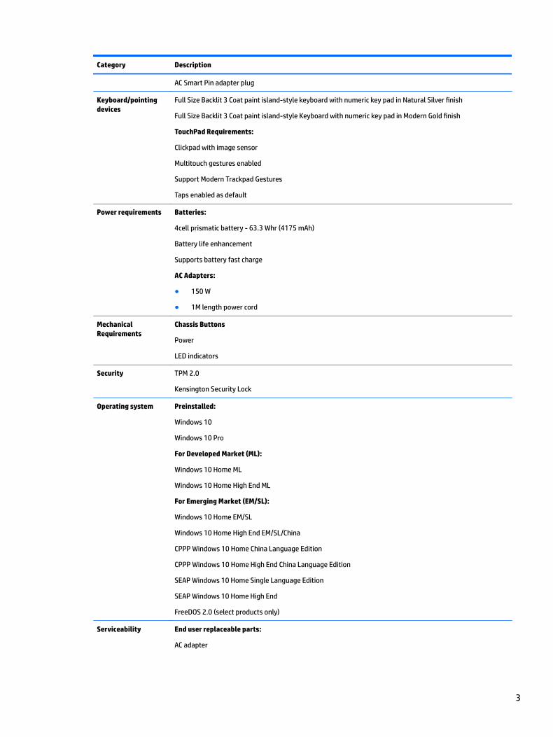
Category Description
AC Smart Pin adapter plug
Keyboard/pointing devices
Full Size Backlit 3 Coat paint island-style keyboard with numeric key pad in Natural Silver finish
Full Size Backlit 3 Coat paint island-style Keyboard with numeric key pad in Modern Gold finish
TouchPad Requirements:
Clickpad with image sensor
Multitouch gestures enabled
Support Modern Trackpad Gestures
Taps enabled as default
Power requirements Batteries:
4cell prismatic battery - 63.3 Whr (4175 mAh)
Battery life enhancement
Supports battery fast charge
AC Adapters:
● 150 W
● 1M length power cord
Mechanical Requirements
Chassis Buttons
Power
LED indicators
Security TPM 2.0
Kensington Security Lock
Operating system Preinstalled:
Windows 10
Windows 10 Pro
For Developed Market (ML):
Windows 10 Home ML
Windows 10 Home High End ML
For Emerging Market (EM/SL):
Windows 10 Home EM/SL
Windows 10 Home High End EM/SL/China
CPPP Windows 10 Home China Language Edition
CPPP Windows 10 Home High End China Language Edition
SEAP Windows 10 Home Single Language Edition
SEAP Windows 10 Home High End
FreeDOS 2.0 (select products only)
Serviceability End user replaceable parts:
AC adapter
3

Category Description
Raw Panel Replacement
4 Chapter 1 Product description

2 External component identification
Right side
Description
(1) Memory card reader (select products only) Reads optional memory cards that enable you to store, manage, share, or access information.
To insert a card:
1. Hold the card label-side up, with connectors facing the computer.
2. Insert the card into the memory card reader, and then press in on the card until it is firmly seated.
To remove a card:
▲ Press in on the card, and then remove it from the memory card reader.
(2) Drive light (select products only) ● Blinking white: The hard drive is being accessed.
● Amber: HP 3D DriveGuard has temporarily parked the hard drive (select products only).
(3) USB 3.0 port Connects an optional USB device, such as a keyboard, mouse, external drive, printer, scanner or USB hub.
(4) HDMI port Connects an optional video or audio device, such as a high-definition television, any compatible digital or audio component, or a high-speed High Definition Multimedia Interface (HDMI) device.
(5) RJ-45 (network) jack/status lights Connects a network cable.
● White: The network is connected.
● Amber: Activity is occurring on the network.
(6) Power connector Connects an AC adapter.
(7) AC adapter and battery light ● White: The AC adapter is connected and the battery is fully charged.
● Blinking white: The AC adapter is disconnected and the battery has reached a low battery level.
Right side 5

Description
● Amber: The AC adapter is connected and the battery is charging.
● Off: The battery is not charging.
Left side
Description
(1) Security cable slot Attaches an optional security cable to the computer.
NOTE: The security cable is designed to act as a deterrent, but it may not prevent the computer from being mishandled or stolen.
(2) USB 2.0 port Connects an optional USB device, such as a keyboard, mouse, external drive, printer, scanner or USB hub.
(3) USB 3.0 port Connects an optional USB device, such as a keyboard, mouse, external drive, printer, scanner or USB hub.
(4) Audio-out (headphone)/Audio-in (microphone) combo jack
Connects optional powered stereo speakers, headphones, earbuds, a headset, or a television audio cable. Also connects an optional headset microphone. This jack does not support optional standalone microphones.
WARNING! To reduce the risk of personal injury, adjust the volume before putting on headphones, earbuds, or a headset. For additional safety information, refer to the Regulatory, Safety, and Environmental Notices.
To access this guide:
▲ Select the Start button, select All apps, select HP Help and Support, and then select HP Documentation.
NOTE: When a device is connected to the jack, the computer speakers are disabled.
6 Chapter 2 External component identification

Display
Component Description
(1) Internal microphones Record sound.
(2) Camera light On: The camera is in use.
(3) Camera Allows you to video chat, record video, or record still images. Some also provide HD (high-definition) or 3D capability, apps for gaming, or facial recognition software like Windows Hello. For details about using Windows Hello, see “Securing your computer and information”.
To use your camera:
● Type camera in the taskbar search box, and then select Camera.
● On select products, type Intel RealSense in the taskbar search box to explore additional features, demos, and apps.
(4) WLAN antennas* Send and receive wireless signals to communicate with wireless local area networks (WLANs).
*The antennas are not visible from the outside of the computer. For optimal transmission, keep the areas immediately around the antennas free from obstructions.
For wireless regulatory notices, see the section of the Regulatory, Safety, and Environmental Notices that applies to your country or region.
To access this guide:
▲ Select the Start button, select All apps, select HP Help and Support, and then select HP Documentation.
Display 7

Top
TouchPad
Component Description
(1) TouchPad zone Reads your finger gestures to move the pointer or activate items on the screen.
(2) Left TouchPad button Functions like the left button on an external mouse.
(3) Right TouchPad button Functions like the right button on an external mouse.
8 Chapter 2 External component identification

Lights
Component Description
(1) Power light ● On: The computer is on.
● Blinking: The computer is in the Sleep state, a power-saving state. The computer shuts off power to the display and other unneeded components.
● Off: The computer is off or in Hibernation. Hibernation is a power-saving state that uses the least amount of power.
(2) Caps lock light On: Caps lock is on, which switches the key input to all capital letters.
(3) Mute light ● Amber: Computer sound is off.
● Off: Computer sound is on.
Top 9

Button and speakers
Component Description
(1) Power button ● When the computer is off, press the button to turn on the computer.
● When the computer is on, press the button briefly to initiate Sleep.
● When the computer is in the Sleep state, press the button briefly to exit Sleep.
● When the computer is in Hibernation, press the button briefly to exit Hibernation.
CAUTION: Pressing and holding down the power button results in the loss of unsaved information.
If the computer has stopped responding and shutdown procedures are ineffective, press and hold the power button down for at least 5 seconds to turn off the computer.
To learn more about your power settings, see your power options.
▲ Type power in the taskbar search box, and then select Power and sleep settings.
‒ or –
Right-click the Start button, and then select Power Options.
(2) Speakers Produce sound.
10 Chapter 2 External component identification
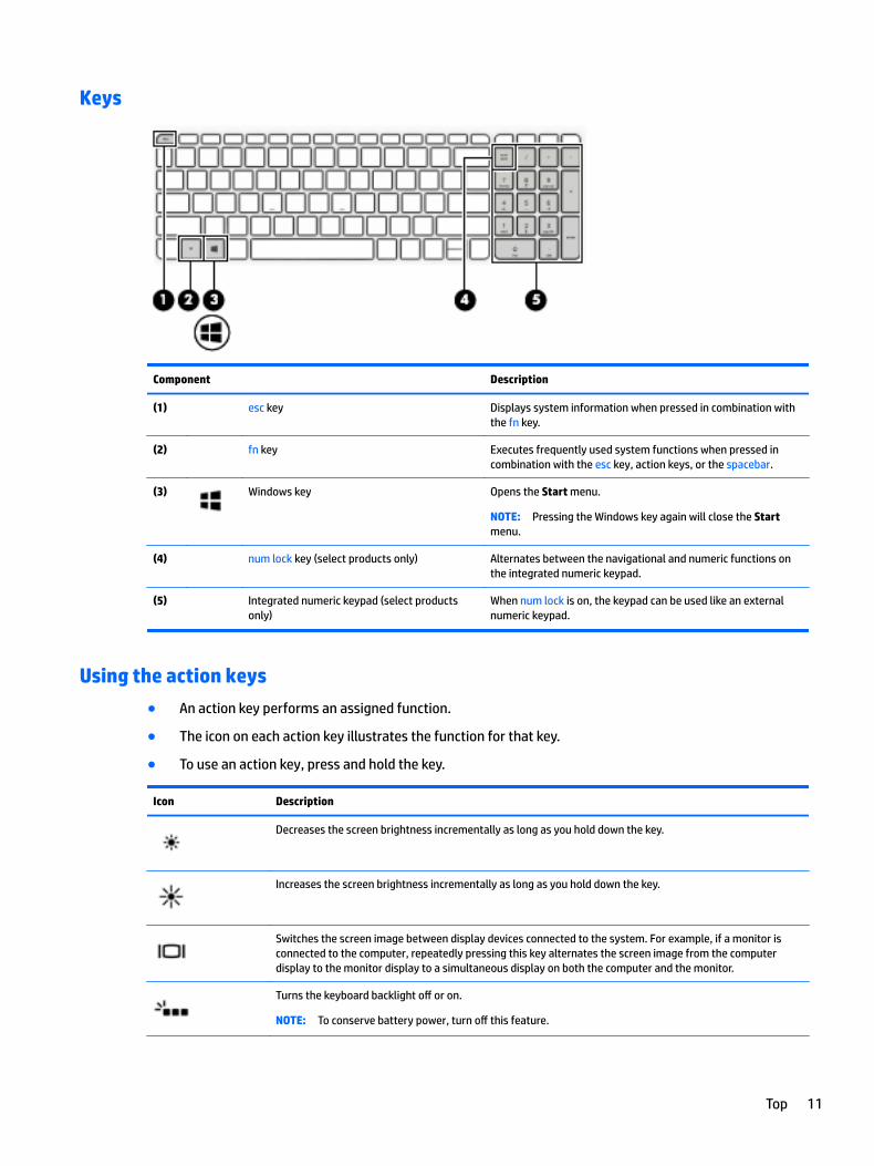
Keys
Component Description
(1) esc key Displays system information when pressed in combination with the fn key.
(2) fn key Executes frequently used system functions when pressed in combination with the esc key, action keys, or the spacebar.
(3) Windows key Opens the Start menu.
NOTE: Pressing the Windows key again will close the Start menu.
(4) num lock key (select products only) Alternates between the navigational and numeric functions on the integrated numeric keypad.
(5) Integrated numeric keypad (select products only)
When num lock is on, the keypad can be used like an external numeric keypad.
Using the action keys
● An action key performs an assigned function.
● The icon on each action key illustrates the function for that key.
● To use an action key, press and hold the key.
Icon Description
Decreases the screen brightness incrementally as long as you hold down the key.
Increases the screen brightness incrementally as long as you hold down the key.
Switches the screen image between display devices connected to the system. For example, if a monitor is connected to the computer, repeatedly pressing this key alternates the screen image from the computer display to the monitor display to a simultaneous display on both the computer and the monitor.
Turns the keyboard backlight off or on.
NOTE: To conserve battery power, turn off this feature.
Top 11

Icon Description
Mutes or restores speaker sound.
Decreases speaker volume incrementally while you hold down the key.
Increases speaker volume incrementally while you hold down the key.
Plays the previous track of an audio CD or the previous section of a DVD or a Blu-ray Disc (BD).
Starts, pauses, or resumes playback of an audio CD, a DVD, or a BD.
Plays the next track of an audio CD or the next section of a DVD or a BD.
Turns the airplane mode and wireless feature on or off.
NOTE: The airplane mode key is also referred to as the wireless button.
NOTE: A wireless network must be set up before a wireless connection is possible.
Bottom
Description
Vents (2) Enable airflow to cool internal components.
12 Chapter 2 External component identification

Description
NOTE: The computer fan starts up automatically to cool internal components and prevent overheating. It is normal for the internal fan to cycle on and off during routine operation.
Bottom 13

Rear
Description
Vent Enables airflow to cool internal components.
NOTE: The computer fan starts up automatically to cool internal components and prevent overheating. It is normal for the internal fan to cycle on and off during routine operation.
Locating system informationImportant system information is located on the bottom edge of the tablet or on the keyboard base. You may need the information when travelling internationally or when you contact support:
(1): Warranty period
(2): Serial number
(3): Product number
(4): Model number
14 Chapter 2 External component identification

Using Windows, briefly press the fn+esc key combination to display the System Information screen, which provides the product name and serial number of your computer, as well as information about the memory, processor, BIOS, and keyboard.
Locating system information 15

3 Illustrated parts catalog
Computer major componentsNOTE: HP continually improves and changes product parts. For complete and current information on supported parts for your computer, go to http://partsurfer.hp.com, select your country or region, and then follow the on-screen instructions.
NOTE: Details about your computer, including model, serial number, product key, and length of warranty, are on the service tag at the bottom of your computer. See Locating system information on page 14 for details.
16 Chapter 3 Illustrated parts catalog
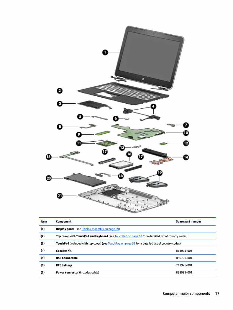
Item Component Spare part number
(1) Display panel (see Display assembly on page 29)
(2) Top cover with TouchPad and keyboard (see TouchPad on page 58 for a detailed list of country codes)
(3) TouchPad (included with top cover) (see TouchPad on page 58 for a detailed list of country codes)
(4) Speaker Kit 858976-001
(5) USB board cable 856729-001
(6) RTC battery 741976-001
(7) Power connector (includes cable) 858021-001
Computer major components 17

Item Component Spare part number
(8) Power button board 858974-001
Power button board cable 858966-001
(9) Solid-state drive
GNRC SSD 128 GB 2280 M2 SATA-3 Value TL 827560-017
GNRC SSD 256 GB 228 0M2 PCIe 3x4SS NVMeTLC TL 847109-005
GNRC SSD512GB 2280M2PCIe3x4SS NVMeTLC TL 847110-002
(10) System board (see System board on page 53)
(11) Memory
4 GB 2133 MHz 1.2v DDR4 shared 820569-005
8 GB 2133 MHz 1.2v DDR4 shared 820570-005
2 GB 2133 MHz 1.2v DDR4 shared 851379-005
GNRC-SODIMM 4GB 2400MHz 1.2v DDR4 862397-855
GNRC-SODIMM 8GB 2400MHz 1.2v DDR4 862398-855
ASSY-SODIMM 2GB 2400MHz 1.2v DDR4 864271-855
(12) WLAN module11AC 7265NV M.2 D0 MOW 793840-005
(13) Heat sink for CPU and graphics 725625-001
(14) Heat sink for products with discrete graphics
For products with discrete graphics 950M/960M/965M 856668-001
For products with discrete graphics GTX1050 920563-001
(15) USB board 858975-001
(16) Hard drive
1 TB 7200 RPM SATA RAW 9.5mm 766644-005
2 TB 5400 RPM SATA RAW 9.5 mm 801808-005
Hard drive cable 858969-001
(17) Hard drive bracket 913937-001
(18) Battery cable 858968-001
(19) Fan 858970-001
(20) Battery
3C 61WH 5.37Ah LI TE03061XL-PR 849910-850
4C 63Wh 4.112A LI TE04063XL-PL 905277-855
(21) Base enclosure
In Natural Silver finish 858963-001
In Modern Gold finish 858964-001
18 Chapter 3 Illustrated parts catalog

Display assembly subcomponents
Item Component Spare part number
(1) Bezel
For non-touch screens 856725-001
For non-touch 3D screens 856726-001
(2) Webcam
GNRC WC 1p NM U3 1080p Intel 3D 781624-005
GNRC WC 1p DM U2 Mjpeg 720p VDH2 PA 833962-011
GNRC WC 1p DM U2 Mjpeg 720p VDH SF 846006-003
3D Webcam cable 859445-001
(3) Raw panel
Display assembly subcomponents 19

Item Component Spare part number
15.6" FHD WLED AntiGlare (1920x1080) slim-flat (3.2mm) SVA, eDP, Special Deal, 220 nits 842484-003
Display panel kit 15.6 AG FHD for touch screens 859098-001
Display panel kit 15.6 AG UHD for touch screens 859099-001
(4) Hinge assembly
For non-touch screens 856741-001
For touch screens 856742-001
(5) Hinge cap assembly for touch screens 856748-001
(6) Hinge cap assembly for non-touch screens 856747-001
(7) WLAN antenna 856923-001
(8) Display cable
Full high-definition display cable for products not equipped with a touch screen 856733-001
Full high-definition display cable for products with a 3D non-touch screen 856734-001
High-definition display cable for products with a non-touch screen 856735-001
High-definition display cable for products with a 3D non-touch screen 856736-001
Full high-definition display cable for products with a touch screen 856737-001
High-definition display cable for products with a touch screen 856738-001
(9) Back cover
In Natural Silver finish, with antenna for non-touch screen 856713-001
In Modern Gold finish, with antenna for non-touch screen 856714-001
In Natural Silver finish, with antenna, for non-touch 3D screens 856716-001
In Modern Gold finish, with antenna, for non-touch 3D screens 856717-001
In Natural Silver finish, with antenna for touch screens 856719-001
In Modern Gold finish, with antenna for touch screens 856720-001
Miscellaneous parts
Component Spare part number
AC adapter
120W adapter PFC S-3P SLIM 4.5MM 710415-001
150W adapter PFC SMART 4.5mm SLIM 776620-001
GNRC DCIN CA 10P STD 4.5mm 120W L50 TL connector 858021-001
Hard drive bracket 913937-001
HP HDMI to VGA adapter 701943-001
Microphone board 857471-001
20 Chapter 3 Illustrated parts catalog

Component Spare part number
HP USB External DVD/RW Drive 747080-001
Power cord
For use in NEMA 213349-009
For use in Europe 213350-009
For use in the United Kingdom 213351-008
For use in Denmark 213353-008
For use in Switzerland 213354-008
For use in Australia 213356-008
For use in South Korea 267836-008
For use in Thailand 285096-006
For use in the People’s Republic of China 286497-008
OPT-917 3-COND 1.0-M-LG ROHS 361240-002
For use in Taiwan 393313-003
For use in Israel 398063-003
For use in India 404827-003
Screw Kit 856752-001
Miscellaneous parts 21

4 Removal and replacement procedures preliminary requirements
Tools requiredYou will need the following tools to complete the removal and replacement procedures:
● Flat-bladed screwdriver
● Magnetic screwdriver
● Phillips P0 and P1 screwdrivers
Service considerationsThe following sections include some of the considerations that you must keep in mind during disassembly and assembly procedures.
NOTE: As you remove each subassembly from the computer, place the subassembly (and all accompanying screws) away from the work area to prevent damage.
Plastic parts
CAUTION: Using excessive force during disassembly and reassembly can damage plastic parts. Use care when handling the plastic
22 Chapter 4 Removal and replacement procedures preliminary requirements

Cables and connectors
CAUTION: When servicing the computer, be sure that cables are placed in their proper locations during the reassembly process. Improper cable placement can damage the computer.
Cables must be handled with extreme care to avoid damage. Apply only the tension required to unseat or seat the cables during removal and insertion. Handle cables by the connector whenever possible. In all cases, avoid bending, twisting, or tearing cables. Be sure that cables are routed in such a way that they cannot be caught or snagged by parts being removed or replaced. Handle flex cables with extreme care; these cables tear easily.
Drive handling
CAUTION: Drives are fragile components that must be handled with care. To prevent damage to the computer, damage to a drive, or loss of information, observe these precautions:
Before removing or inserting a hard drive, shut down the computer. If you are unsure whether the computer is off or in Hibernation, turn the computer on, and then shut it down through the operating system.
Before handling a drive, be sure that you are discharged of static electricity. While handling a drive, avoid touching the connector.
Before removing an optical drive, be sure that a disc is not in the drive and be sure that the optical drive tray is closed.
Handle drives on surfaces covered with at least one inch of shock-proof foam.
Avoid dropping drives from any height onto any surface.
After removing a hard drive or an optical drive, place it in a static-proof bag.
Avoid exposing an internal hard drive to products that have magnetic fields, such as monitors or speakers.
Avoid exposing a drive to temperature extremes or liquids.
If a drive must be mailed, place the drive in a bubble pack mailer or other suitable form of protective packaging and label the package “FRAGILE.”
Service considerations 23

Grounding guidelines
Electrostatic discharge damage
Electronic components are sensitive to electrostatic discharge (ESD). Circuitry design and structure determine the degree of sensitivity. Networks built into many integrated circuits provide some protection, but in many cases, ESD contains enough power to alter device parameters or melt silicon junctions.
A discharge of static electricity from a finger or other conductor can destroy static-sensitive devices or microcircuitry. Even if the spark is neither felt nor heard, damage may have occurred.
An electronic device exposed to ESD may not be affected at all and can work perfectly throughout a normal cycle. Or the device may function normally for a while, then degrade in the internal layers, reducing its life expectancy.
CAUTION: To prevent damage to the computer when you are removing or installing internal components, observe these precautions:
Keep components in their electrostatic-safe containers until you are ready to install them.
Before touching an electronic component, discharge static electricity by using the guidelines described in this section.
Avoid touching pins, leads, and circuitry. Handle electronic components as little as possible.
If you remove a component, place it in an electrostatic-safe container.
The following table shows how humidity affects the electrostatic voltage levels generated by different activities.
CAUTION: A product can be degraded by as little as 700 V.
Typical electrostatic voltage levels
Relative humidity
Event 10% 40% 55%
Walking across carpet 35,000 V 15,000 V 7,500 V
Walking across vinyl floor 12,000 V 5,000 V 3,000 V
Motions of bench worker 6,000 V 800 V 400 V
Removing DIPS from plastic tube 2,000 V 700 V 400 V
Removing DIPS from vinyl tray 11,500 V 4,000 V 2,000 V
Removing DIPS from plastic foam 14,500 V 5,000 V 3,500 V
Removing bubble pack from PCB 26,500 V 20,000 V 7,000 V
Packing PCBs in foam-lined box 21,000 V 11,000 V 5,000 V
24 Chapter 4 Removal and replacement procedures preliminary requirements
Packaging and transporting guidelines
Follow these grounding guidelines when packaging and transporting equipment:
● To avoid hand contact, transport products in static-safe tubes, bags, or boxes.
● Protect ESD-sensitive parts and assemblies with conductive or approved containers or packaging.
● Keep ESD-sensitive parts in their containers until the parts arrive at static-free workstations.
● Place items on a grounded surface before removing items from their containers.
● Always be properly grounded when touching a component or assembly.
● Store reusable ESD-sensitive parts from assemblies in protective packaging or nonconductive foam.
● Use transporters and conveyors made of antistatic belts and roller bushings. Be sure that mechanized equipment used for moving materials is wired to ground and that proper materials are selected to avoid static charging. When grounding is not possible, use an ionizer to dissipate electric charges.
Workstation guidelines
Follow these grounding workstation guidelines:
● Cover the workstation with approved static-shielding material.
● Use a wrist strap connected to a properly grounded work surface and use properly grounded tools and equipment.
● Use conductive field service tools, such as cutters, screwdrivers, and vacuums.
● When fixtures must directly contact dissipative surfaces, use fixtures made only of static safe materials.
● Keep the work area free of nonconductive materials, such as ordinary plastic assembly aids and plastic foam.
● Handle ESD-sensitive components, parts, and assemblies by the case or PCM laminate. Handle these items only at static-free workstations.
● Avoid contact with pins, leads, or circuitry.
● Turn off power and input signals before inserting or removing connectors or test equipment.
Grounding guidelines 25
Equipment guidelines
Grounding equipment must include either a wrist strap or a foot strap at a grounded workstation.
● When seated, wear a wrist strap connected to a grounded system. Wrist straps are flexible straps with a minimum of one megohm ±10% resistance in the ground cords. To provide proper ground, wear a strap snugly against the skin at all times. On grounded mats with banana-plug connectors, use alligator clips to connect a wrist strap.
● When standing, use foot straps and a grounded floor mat. Foot straps (heel, toe, or boot straps) can be used at standing workstations and are compatible with most types of shoes or boots. On conductive floors or dissipative floor mats, use foot straps on both feet with a minimum of one megohm resistance between the operator and ground. To be effective, the conductive equipment must be worn in contact with the skin.
The following grounding equipment is recommended to prevent electrostatic damage:
● Antistatic tape
● Antistatic smocks, aprons, and sleeve protectors
● Conductive bins and other assembly or soldering aids
● Nonconductive foam
● Conductive tabletop workstations with ground cords of one megohm resistance
● Static-dissipative tables or floor mats with hard ties to the ground
● Field service kits
● Static awareness labels
● Material-handling packages
● Nonconductive plastic bags, tubes, or boxes
● Metal tote boxes
● Electrostatic voltage levels and protective materials
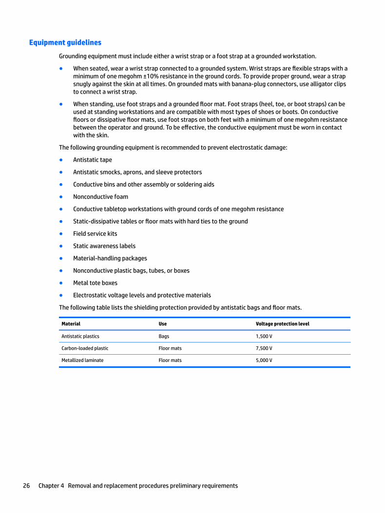
The following table lists the shielding protection provided by antistatic bags and floor mats.
Material Use Voltage protection level
Antistatic plastics Bags 1,500 V
Carbon-loaded plastic Floor mats 7,500 V
Metallized laminate Floor mats 5,000 V
26 Chapter 4 Removal and replacement procedures preliminary requirements
5 Removal and replacement procedures for authorized service provider parts
CAUTION: Components described in this chapter should be accessed only by an authorized service provider. Accessing these parts can damage the computer or void the warranty.
CAUTION: This computer does not have user-replaceable parts. Only HP authorized service providers should perform the removal and replacement procedures described here. Accessing the internal part could damage the computer or void the warranty.
Component replacement proceduresNOTE: Details about your computer, including model, serial number, product key, and length of warranty, are on the service tag at the bottom of your computer. See Locating system information on page 14 for details.
NOTE: HP continually improves and changes product parts. For complete and current information on supported parts for your computer, go to http://partsurfer.hp.com, select your country or region, and then follow the on-screen instructions.
There are as many as 61 screws that must be removed, replaced, and/or loosened when servicing the parts described in this chapter. Make special note of each screw size and location during removal and replacement.
Base enclosure
Description Spare part number
Base enclosure
In Natural Silver finish 858963-001
In Modern Gold finish 858964-001
Before disassembling the computer, follow these steps:
1. Turn off the computer. If you are unsure whether the computer is off or in Hibernation, turn the computer on, and then shut it down through the operating system.
2. Disconnect the power from the computer by unplugging the power cord from the computer.
3. Disconnect all external devices from the computer.
Remove the base enclosure:
1. Position the computer upside down on a flat surface.
Component replacement procedures 27

2. Remove the rubber strip (1), and then remove 10 Phillips 2x5 screws (2) and (3).
3. Slide a nylon flake tool around the edge of the base enclosure to loosen it (1), taking care not to damage the internal clips, and then remove the base enclosure (2).
28 Chapter 5 Removal and replacement procedures for authorized service provider parts

Display assembly
IMPORTANT: Make special note of each screw and screw lock size and location during removal and replacement.
Before removing the display assembly, follow these steps:
1. Shut down the computer.
2. Disconnect all external devices connected to the computer.
3. Disconnect the power from the computer by first unplugging the power cord from the AC outlet and then unplugging the AC adapter from the computer.
4. Remove the base enclosure.
Remove the display assembly:
1. Remove 3 Phillips 2.5x6.0 screws from the left hinge and 3 Phillips screws 2.5x6.0 from the right hinge bracket (1), and then lift the hinge brackets to remove them (2).
Component replacement procedures 29

2. Disconnect the WLAN antenna cable (1), and remove the tape holding it in place (2), disconnect the display cable (3), and then release the cable from the routing channels (4).
3. Rotate the display assembly (1), and then remove the display assembly from the base enclosure (2).
Reverse this procedure to install the display assembly.
30 Chapter 5 Removal and replacement procedures for authorized service provider parts

Hard drive
Description Spare part number
Hard drive
1 TB 7200 RPM SATA RAW 9.5mm 766644-005
2 TB 5400 RPM SATA RAW 9.5 mm 801808-005
Hard drive bracket 913937-001
Hard drive cable 858969-001
IMPORTANT: Make special note of each screw and screw lock size and location during removal and replacement.
Before removing the hard drive, follow these steps:
1. Shut down the computer.
2. Disconnect all external devices connected to the computer.
3. Disconnect the power from the computer by first unplugging the power cord from the AC outlet and then unplugging the AC adapter from the computer.
4. Remove the base enclosure (see Base enclosure on page 27), and then remove the following components:
▲ Display assembly (see Display assembly on page 29).
Remove the hard drive:
▲ Disconnect the hard drive cable (1), slide the hard drive horizontally (2), loosen the side brackets (3), and then lift the hard drive (4) to remove it (5).
Component replacement procedures 31

Reverse this procedure to install the hard drive.
If it is necessary to disassemble the hard drive, follow these steps:
▲ Remove the hard drive connector (1), and then remove the side brackets (2).
Reverse this procedure to reassemble the hard drive.
32 Chapter 5 Removal and replacement procedures for authorized service provider parts

SSD (M.2)
Description Spare part number
GNRC SSD 128 GB 2280 M2 SATA-3 Value TL 827560-017
GNRC SSD 256 GB 228 0M2 PCIe 3x4SS NVMeTLC TL 847109-005
GNRC SSD512GB 2280M2PCIe3x4SS NVMeTLC TL 847110-002
Before removing the SSD, follow these steps:
1. Turn off the computer. If you are unsure whether the computer is off or in Hibernation, turn the computer on, and then shut it down through the operating system.
2. Disconnect the power from the computer by unplugging the power cord from the computer.
3. Disconnect all external devices from the computer.
4. Remove the following components:
a. Display assembly (see Display assembly on page 29).
b. Hard drive (see Hard drive on page 31).
Remove the SSD:
1. Remove the Phillips M2.0 x 2.5 screw (1) that secures the SSD to the system board.
2. Remove the SSD (2) by pulling the drive away from the slot at an angle.
Reverse this procedure to install the SSD.
Component replacement procedures 33

Memory
Description Spare part number
Memory
4 GB 2133 MHz 1.2v DDR4 shared 820569-005
8 GB 2133 MHz 1.2v DDR4 shared 820570-005
2 GB 2133 MHz 1.2v DDR4 shared 851379-005
GNRC-SODIMM 4GB 2400MHz 1.2v DDR4 862397-855
GNRC-SODIMM 8GB 2400MHz 1.2v DDR4 862398-855
ASSY-SODIMM 2GB 2400MHz 1.2v DDR4 864271-855
IMPORTANT: Make special note of each screw and screw lock size and location during removal and replacement.
Before removing the memory, follow these steps:
1. Shut down the computer.
2. Disconnect all external devices connected to the computer.
3. Disconnect the power from the computer by first unplugging the power cord from the AC outlet and then unplugging the AC adapter from the computer.
4. Remove the base enclosure (see Base enclosure on page 27), and then remove the following components:
a. Display assembly (see Display assembly on page 29).
b. Hard drive (see Hard drive on page 31).
c. SSD (see SSD (M.2) on page 33).
If you are replacing a memory module, remove the existing memory module:
1. Lift the clear film covering the memory module.
2. Pull away the retention clips (1) on each side of the memory module.
The memory module tilts up.
34 Chapter 5 Removal and replacement procedures for authorized service provider parts

3. Grasp the edge of the memory module (2), and then gently pull the memory module out of the memory module slot.
CAUTION: To prevent damage to the memory module, hold the memory module by the edges only. Do not touch the components on the memory module.
To protect a memory module after removal, place it in an electrostatic-safe container.
To install a memory module:
CAUTION: To prevent damage to the memory module, hold the memory module by the edges only. Do not touch the components on the memory module.
1. Align the notched edge (1) of the memory module with the tab in the memory module slot.
Component replacement procedures 35

2. With the memory module at a 45-degree angle from the surface of the memory module compartment (2), press the module into the memory module slot until it is seated.
3. Gently press the memory module down (3), applying pressure to both the left and right edges of the memory module, until the retention clips snap into place.
CAUTION: To prevent damage to the memory module, be sure that you do not bend the memory module.
36 Chapter 5 Removal and replacement procedures for authorized service provider parts

WLAN module
Description Spare part number
WLAN module, 11AC 7265NV M.2 D0 MOW 793840-005
IMPORTANT: Make special note of each screw and screw lock size and location during removal and replacement.
Before removing the WLAN module, follow these steps:
1. Shut down the computer.
2. Disconnect all external devices connected to the computer.
3. Disconnect the power from the computer by first unplugging the power cord from the AC outlet and then unplugging the AC adapter from the computer.
4. Remove the base enclosure (see Base enclosure on page 27), and then remove the following components:
a. Display assembly (see Display assembly on page 29).
b. Hard drive (see Hard drive on page 31).
c. SSD (see SSD (M.2) on page 33).
d. Memory (see Memory on page 34).
Remove the WLAN module:
1. Carefully disconnect 2 antenna cables (1).
2. Remove 1 Phillips 2.0x2.5 screw (2), and then remove the WLAN module (3).
Component replacement procedures 37

Reverse this procedure to install the WLAN module.
38 Chapter 5 Removal and replacement procedures for authorized service provider parts

Battery
Description Spare part number
Battery
3C 61WH 5.37Ah LI TE03061XL-PR 849910-850
4C 63Wh 4.112A LI TE04063XL-PL 905277-855
Battery cable 858968-001
Remove the battery:
WARNING! To reduce potential safety issues, use only the user-replaceable battery provided with the computer, a replacement battery provided by HP, or a compatible battery purchased from HP.
CAUTION: Removing a user-replaceable battery that is the sole power source for the computer can cause loss of information. To prevent loss of information, save your work or shut down the computer through Windows before removing the battery.
Before removing the battery, follow these steps:
1. Shut down the computer.
2. Disconnect all external devices connected to the computer.
3. Disconnect the power from the computer by first unplugging the power cord from the AC outlet and then unplugging the AC adapter from the computer.
4. Remove the base enclosure (see Base enclosure on page 27), and then remove the following components:
a. Display assembly (see Display assembly on page 29).
b. Hard drive (see Hard drive on page 31).
c. SSD (see SSD (M.2) on page 33).
d. Memory (see Memory on page 34).
e. WLAN module (see WLAN module on page 37).
1. Disconnect the battery cable from the system board(1), release the battery cable from the routing channels (2), and then lift the battery cable to remove it (3).
Component replacement procedures 39

40 Chapter 5 Removal and replacement procedures for authorized service provider parts

2. Remove 4 Phillips 2x5 screws (1), lift the battery (2), and then slide the battery to remove it from the connector (3).
To insert the battery, reverse the removal procedures.
Component replacement procedures 41

USB board
Description Spare part number
USB board 858975-001
USB board cable 856729-001
IMPORTANT: Make special note of each screw and screw lock size and location during removal and replacement
Before removing the SD card reader board, follow these steps:
1. Shut down the computer.
2. Disconnect all external devices connected to the computer.
3. Disconnect the power from the computer by first unplugging the power cord from the AC outlet and then unplugging the AC adapter from the computer.
4. Remove the base enclosure (see Base enclosure on page 27), and then remove the following components:
a. Display assembly (see Display assembly on page 29).
b. Hard drive (see Hard drive on page 31).
c. SSD (see SSD (M.2) on page 33).
d. Memory (see Memory on page 34).
e. WLAN module (see WLAN module on page 37).
f. Battery (see Battery on page 39).
Remove the USB board:
▲ Disconnect the zero-insertion force (ZIF) connector (1), remove the USB board cable (2), disconnect 2 zero-insertion force (ZIF) connectors (3) and (4), remove 1 Phillips screw (5), and then lift the USB board to remove it (6).
42 Chapter 5 Removal and replacement procedures for authorized service provider parts

Reverse this procedure to install the USB board.
Power button board
Description Spare part number
Power button board 858974-001
Power button board cable 858966-001
IMPORTANT: Make special note of each screw and screw lock size and location during removal and replacement
Before removing the power button board, follow these steps:
1. Shut down the computer.
2. Disconnect all external devices connected to the computer.
3. Disconnect the power from the computer by first unplugging the power cord from the AC outlet and then unplugging the AC adapter from the computer.
4. Remove the base enclosure (see Base enclosure on page 27), and then remove the following components:
a. Display assembly (see Display assembly on page 29).
b. Hard drive (see Hard drive on page 31).
c. SSD (see SSD (M.2) on page 33).
d. Memory (see Memory on page 34).
e. WLAN module (see WLAN module on page 37).
Component replacement procedures 43

f. Battery (see Battery on page 39).
g. USB (see USB board on page 42).
Remove the power button board:
▲ Remove 1 Phillips screw (1), lift the power button board at an angle (2), and then remove it (3).
Reverse this procedure to install the power button board.
44 Chapter 5 Removal and replacement procedures for authorized service provider parts

Fan
Description Spare part number
Fan 858970-001
IMPORTANT: Make special note of each screw and screw lock size and location during removal and replacement.
Before removing the heat sink and the fan, follow these steps:
1. Shut down the computer.
2. Disconnect all external devices connected to the computer.
3. Disconnect the power from the computer by first unplugging the power cord from the AC outlet and then unplugging the AC adapter from the computer.
4. Remove the base enclosure (see Base enclosure on page 27), and then remove the following components:
a. Display assembly (see Display assembly on page 29).
b. Hard drive (see Hard drive on page 31).
c. SSD (see SSD (M.2) on page 33).
d. Memory (see Memory on page 34).
e. WLAN module (see WLAN module on page 37).
f. Battery (see Battery on page 39).
g. USB (see USB board on page 42).
h. Power button board (see Power button board on page 43).
Remove the fan:
▲ Disconnect the fan cables (1), release the cables from the threading channels (2), remove 4 Phillips 2x5 screws from the fan (3), and then lift the fan assembly to remove it (4).
Component replacement procedures 45

Reverse this procedure to install the fan.
Heat sink for discrete graphics memory
Description Spare part number
Heat sink for products with discrete graphics
For products with discrete graphics 950M/960M/965M 856668-001
For products with discrete graphics GTX1050 920563-001
Before removing the heat sink for discrete graphics memory, follow these steps:
1. Turn off the computer. If you are unsure whether the computer is off or in Hibernation, turn the computer on, and then shut it down through the operating system.
2. Disconnect the power from the computer by unplugging the power cord from the computer.
3. Disconnect all external devices from the computer.
4. Remove the base enclosure (see Base enclosure on page 27), and then remove the following components:
a. Display assembly (see Display assembly on page 29).
b. Hard drive (see Hard drive on page 31).
c. SSD (see SSD (M.2) on page 33).
d. Memory (see Memory on page 34).
e. WLAN module (see WLAN module on page 37).
f. Battery (see Battery on page 39).
46 Chapter 5 Removal and replacement procedures for authorized service provider parts

g. USB (see USB board on page 42).
h. Power button board (see Power button board on page 43).
i. Fan (see Fan on page 45).
Remove the heat sink for discrete graphics memory:
1. Remove the 6 Phillips M2.0 screws (1) and then carefully lift the heat sink (2) to remove it from the system board.
Component replacement procedures 47

2. The following illustration shows the replacement thermal material locations. The thermal material must be thoroughly cleaned from the surfaces of the heat sink and the system board components each time the heat sink is removed. Replacement thermal material is included with the heat sink and system board spare part kits.
Thermal paste is used on the system board components (1), (3) and on the heat sink areas (2), (4) that service them.
Reverse this procedure to install the heat sink for discrete graphics memory.
Heat sink for CPU and graphics
Heat sink
Heat sink for CPU and graphics 725625-001
Before removing the heat sink for CPU and graphics, follow these steps:
1. Turn off the computer. If you are unsure whether the computer is off or in Hibernation, turn the computer on, and then shut it down through the operating system.
2. Disconnect the power from the computer by unplugging the power cord from the computer.
3. Disconnect all external devices from the computer.
4. Remove the base enclosure (see Base enclosure on page 27), and then remove the following components:
a. Display assembly (see Display assembly on page 29).
b. Hard drive (see Hard drive on page 31).
c. SSD (see SSD (M.2) on page 33).
d. Memory (see Memory on page 34).
48 Chapter 5 Removal and replacement procedures for authorized service provider parts

e. WLAN module (see WLAN module on page 37).
f. Battery (see Battery on page 39).
g. USB (see USB board on page 42).
h. Power button board (see Power button board on page 43).
i. Fan (see Fan on page 45).
j. Heat sink for discrete graphics (see Heat sink for discrete graphics memory on page 46).
Remove the heat sink for CPU and graphics:
1. Remove the 2 Phillips screws (1) and then remove the heat sink (2) from the system board.
Component replacement procedures 49

2. The following illustration shows the replacement thermal material locations. The thermal material must be thoroughly cleaned from the surfaces of the heat sink and the system board components each time the heat sink is removed. Replacement thermal material is included with the heat sink and system board spare part kits.
Thermal paste is used on the system board components (1) and on the heat sink areas (2) that service them.
Reverse this procedure to install the heat sink for CPU and graphics.
50 Chapter 5 Removal and replacement procedures for authorized service provider parts

Speakers
NOTE: The speaker spare part kit includes the cable.
Description Spare part number
Speaker Kit 858976-001
IMPORTANT: Make special note of each screw and screw lock size and location during removal and replacement.
Before removing the speakers, follow these steps:
1. Shut down the computer.
2. Disconnect all external devices connected to the computer.
3. Disconnect the power from the computer by first unplugging the power cord from the AC outlet and then unplugging the AC adapter from the computer.
4. Remove the base enclosure (see Base enclosure on page 27), and then remove the following components:
a. Display assembly (see Display assembly on page 29).
b. Hard drive (see Hard drive on page 31).
c. SSD (see SSD (M.2) on page 33).
d. Memory (see Memory on page 34).
e. WLAN module (see WLAN module on page 37).
f. Battery (see Battery on page 39).
g. USB (see USB board on page 42).
h. Power button board (see Power button board on page 43).
i. Fan (see Fan on page 45).
j. Heat sink for discrete graphics (see Heat sink for discrete graphics memory on page 46).
k. Heat sink for CPU and graphics (see Heat sink for CPU and graphics on page 48).
Remove the speakers:
1. Disconnect the right speaker cable (1).
Component replacement procedures 51

2. Lift the left speaker and the right speaker, and then remove them (2) .
Reverse this procedure to install the speakers.
52 Chapter 5 Removal and replacement procedures for authorized service provider parts

System board
Description Spare part number
System board
Intel i7-6700HQ system board with a non-Windows operating system 856673-001
Intel i7-6700HQ system board with a Windows operating system 856673-601
Intel i5-6300HQ system board with a non-Windows operating system 856674-001
Intel 2GB i5-6300HQ system board with a Windows operating system 856674-601
Intel i3-6100H system board with a non-Windows operating system 856675-001
Intel i3-6100H system board with a Windows operating system 856675-601
Intel i7-6700HQ system board with a non-Windows operating system 856676-001
Intel i7-6700HQ system board with a Windows operating system 856676-601
Intel i5-6300HQ system board with a non-Windows operating system 856677-001
Intel i5-6300HQ system board with a Windows operating system 856677-601
Intel i7-6700HQ system board with a non-Windows operating system 856678-001
Intel i7-6700HQ system board with a Windows operating system 856678-601
Intel i5-6300HQ system board with a non-Windows operating system 856679-001
Intel i5-6300HQ system board with a Windows operating system 856679-601
Intel i7-7700HQ system board with 2GB discrete memory GTX1050M and a non-Windows operating system 914770-001
Intel i7-7700HQ system board with 2GB discrete memory GTX1050M and a Windows operating system 914770-601
Intel i5-7300 system board with 2GB discrete memory GTX1050M and a non-Windows operating system 914771-001
Intel i5-7300 system board with 2GB discrete memory GTX1050M and a Windows operating system 914771-601
Intel i7-7700HQ system board with 4GB discrete memory GTX1050M and a non-Windows operating system 914772-001
Intel i7-7700HQ system board with 4GB discrete memory GTX1050M and a Windows operating system 914772-601
Intel i5-7300 system board with 2GB discrete memory GTX1050M and a non-Windows operating system 914773-001
Intel i5-7300 system board with 2GB discrete memory GTX1050M and a Windows operating system 914773-601
IMPORTANT: Make special note of each screw and screw lock size and location during removal and replacement.
Before removing the system board, follow these steps:
1. Shut down the computer.
2. Disconnect all external devices connected to the computer.
3. Disconnect the power from the computer by first unplugging the power cord from the AC outlet and then unplugging the AC adapter from the computer.
4. Remove the base enclosure (see Base enclosure on page 27), and then remove the following components:
Component replacement procedures 53

a. Display assembly (see Display assembly on page 29).
b. Hard drive (see Hard drive on page 31).
c. SSD (see SSD (M.2) on page 33).
d. Memory (see Memory on page 34).
e. WLAN module (see WLAN module on page 37).
f. Battery (see Battery on page 39).
g. USB (see USB board on page 42).
h. Power button board (see Power button board on page 43).
i. Fan (see Fan on page 45).
j. Heat sink for discrete graphics (see Heat sink for discrete graphics memory on page 46).
k. Heat sink for CPU and graphics (see Heat sink for CPU and graphics on page 48).
Remove the system board:
1. Disconnect the following zero-insertion force (ZIF) connectors from the system board:.
● Wireless antenna cable (1)
● Speaker cable (2)
● Keyboard cable (3)
● Display cable (4)
● USB board cable (5)
● TouchPad cable (6)
● Memory cable (7)
54 Chapter 5 Removal and replacement procedures for authorized service provider parts

2. Remove 1 Phillips 2x5 screw (1), lift the system board (2), and then remove it (3).
Reverse this procedure to install the system board.
RTC battery
Description Spare part number
RTC battery 741976-001
IMPORTANT: Make special note of each screw and screw lock size and location during removal and replacement
Before removing the RTC battery, follow these steps:
1. Shut down the computer.
2. Disconnect all external devices connected to the computer.
3. Disconnect the power from the computer by first unplugging the power cord from the AC outlet and then unplugging the AC adapter from the computer.
4. Remove the base enclosure (see Base enclosure on page 27), and then remove the following components:
▲ Remove the base enclosure (see Base enclosure on page 27), and then remove the following components:
i. Display assembly (see Display assembly on page 29).
ii. Hard drive (see Hard drive on page 31).
iii. SSD (see SSD (M.2) on page 33).
iv. Memory (see Memory on page 34).
Component replacement procedures 55

v. WLAN module (see WLAN module on page 37).
vi. Battery (see Battery on page 39).
vii. USB (see USB board on page 42).
viii. Power button board (see Power button board on page 43).
ix. Fan (see Fan on page 45).
x. Heat sink for discrete graphics (see Heat sink for discrete graphics memory on page 46).
xi. Heat sink for CPU and graphics (see Heat sink for CPU and graphics on page 48).
xii. System board (see System board on page 53).
Remove the RTC battery:
▲ Disconnect the RTC battery (1), and then lift to remove it (2).
Reverse this procedure to install the RTC battery.
Power connector
Description Spare part number
Power connector, DC-IN CAL50 8p 4.5mm90W 8P15 SF 808155-010
IMPORTANT: Make special note of each screw and screw lock size and location during removal and replacement
Before removing the power connector, follow these steps:
1. Shut down the computer.
2. Disconnect all external devices connected to the computer.
56 Chapter 5 Removal and replacement procedures for authorized service provider parts

3. Disconnect the power from the computer by first unplugging the power cord from the AC outlet and then unplugging the AC adapter from the computer.
4. Remove the base enclosure (see Base enclosure on page 27), and then remove the following components:
a. Display assembly (see Display assembly on page 29).
b. Hard drive (see Hard drive on page 31).
c. SSD (see SSD (M.2) on page 33).
d. Memory (see Memory on page 34).
e. WLAN module (see WLAN module on page 37).
f. Battery (see Battery on page 39).
g. USB (see USB board on page 42).
h. Power button board (see Power button board on page 43).
i. Fan (see Fan on page 45).
j. Heat sink for discrete graphics (see Heat sink for discrete graphics memory on page 46).
k. Heat sink for CPU and graphics (see Heat sink for CPU and graphics on page 48).
l. System board (see System board on page 53).
m. RTC battery (see RTC battery on page 55).
Remove the power connector:
▲ Disconnect the connector cable, and then remove the power connector.
Reverse this procedure to install the power connector.
Component replacement procedures 57

TouchPad
Description Spare part number
TouchPad board 860363-001
TouchPad cable 858967-001
Top cover with TouchPad and Backlit Keyboard in Natural Silver finish 858971-001
Top cover with TouchPad and Backlit Keyboard in Modern Gold finish 858972-001
For use in country or region
Spare part number
For use in country or region
Spare part number
For use in country or region
Spare part number
Belgium -A41 India -002 Slovenia -BA1
Bulgaria -261 Israel -BB1 Spain -071
Canada -DB1 Italy -061 The Netherlands -B31
Czech Republic and Slovakia
-FL1 Northern Africa -FP1 Switzerland -BG1
Denmark, Norway, Finland, and Sweden
-DH1 Norway -091 Taiwan -AB1
France -051 Portugal -131 Thailand -281
Germany -041 Romania -271 Turkey -141
Greece -151 Russia -251 United Kingdom -031
Hungary -211 Saudi Arabia -171 United States -001
Iceland -DD1
IMPORTANT: Make special note of each screw and screw lock size and location during removal and replacement
Before removing the TouchPad, follow these steps:
1. Shut down the computer.
2. Disconnect all external devices connected to the computer.
3. Disconnect the power from the computer by first unplugging the power cord from the AC outlet and then unplugging the AC adapter from the computer.
4. Remove the base enclosure (see Base enclosure on page 27), and then remove the following components:
a. Display assembly (see Display assembly on page 29).
b. Hard drive (see Hard drive on page 31).
c. SSD (see SSD (M.2) on page 33).
d. Memory (see Memory on page 34).
e. WLAN module (see WLAN module on page 37).
58 Chapter 5 Removal and replacement procedures for authorized service provider parts

f. Battery (see Battery on page 39).
g. USB (see USB board on page 42).
h. Power button board (see Power button board on page 43).
i. Fan (see Fan on page 45).
j. Heat sink for discrete graphics (see Heat sink for discrete graphics memory on page 46).
k. Heat sink for CPU and graphics (see Heat sink for CPU and graphics on page 48).
l. System board (see System board on page 53).
m. RTC battery (see RTC battery on page 55).
n. Power connector (see Power connector on page 56).
Remove the TouchPad:
1. Remove 3 Phillips 2.0x2.0 screws (1), and then lift the TouchPad board (2) to remove it.
2. Disconnect the TouchPad cable (1).
3. Remove 3 Phillips 2.0x2.5 screws (2).
Component replacement procedures 59

4. Lift the TouchPad (3), and then remove it (4).
Reverse this procedure to install the TouchPad.
60 Chapter 5 Removal and replacement procedures for authorized service provider parts

Display panel
Description Spare part number
Bezel
For non-touch screens 856725-001
For non-touch 3D screens 856726-001
Display panel
15.6" FHD WLED AntiGlare (1920x1080) slim-flat (3.2mm) SVA, eDP, Special Deal, 220 nits 842484-003
Display panel kit 15.6 AG FHD for touch screens 859098-001
Display panel kit 15.6 AG UHD for touch screens 859099-001
Hinge assembly
For non-touch screens 856741-001
For touch screens 856742-001
Hinge cap assembly
For non-touch screens 856747-001
For touch screens 856748-001
Display cable
Full high-definition display cable for products not equipped with a touch screen 856733-001
Full high-definition display cable for products with a 3D non-touch screen 856734-001
High-definition display cable for products with a non-touch screen 856735-001
High-definition display cable for products with a 3D non-touch screen 856736-001
Full high-definition display cable for products with a touch screen 856737-001
High-definition display cable for products with a touch screen 856738-001
WLAN antenna cable 856923-001
Back cover
In Natural Silver finish, with antenna for non-touch screen 856713-001
In Modern Gold finish, with antenna for non-touch screen 856714-001
In Natural Silver finish, with antenna, for non-touch 3D screens 856716-001
In Modern Gold finish, with antenna, for non-touch 3D screens 856717-001
In Natural Silver finish, with antenna for touch screens 856719-001
In Modern Gold finish, with antenna for touch screens 856720-001
IMPORTANT: Make special note of each screw and screw lock size and location during removal and replacement.
Before removing the display assembly, follow these steps:
Component replacement procedures 61

1. Shut down the computer.
2. Disconnect all external devices connected to the computer.
3. Disconnect the power from the computer by first unplugging the power cord from the AC outlet and then unplugging the AC adapter from the computer.
4. Remove the base enclosure (see Base enclosure on page 27), and then remove the following components:
a. Display assembly (see Display assembly on page 29).
b. Hard drive (see Hard drive on page 31).
c. SSD (see SSD (M.2) on page 33).
d. Memory (see Memory on page 34).
e. WLAN module (see WLAN module on page 37).
f. Battery (see Battery on page 39).
g. USB (see USB board on page 42).
h. Power button board (see Power button board on page 43).
i. Fan (see Fan on page 45).
j. Heat sink for discrete graphics (see Heat sink for discrete graphics memory on page 46).
k. Heat sink for CPU and graphics (see Heat sink for CPU and graphics on page 48).
l. System board (see System board on page 53).
m. RTC battery (see RTC battery on page 55).
n. Power connector (see Power connector on page 56).
o. TouchPad (see Power connector on page 56).
Remove the display panel:
1. Slide a nylon flake tool (1) around the outer edge of the bezel to release the bezel from the screen (2).
62 Chapter 5 Removal and replacement procedures for authorized service provider parts

2. Starting on the top edge (1), loosen the display bezel, disconnecting the plastic clips to release the edge of the bezel. Continue on the left and right edges (2) and then bottom edge (3), and then lift the display bezel (4) to remove it.
NOTE: The webcam can be removed after removing the display bezel (see Webcam on page 67) and before removing the display panel.
3. Remove 4 Phillips 2.0x2.5 screws from the display panel (1), and then lift the display panel (2) to remove it.
Component replacement procedures 63

4. Rotate the display panel (1), disconnect the display cable (2) from the display panel (3), and then lift the display panel (4) to remove it.
5. Remove 1 Phillips 2.5x6.0 screw from the top of each hinge bracket (1) and 3 Phillips 2.5x6.0 screws from each hinge (2), remove the hinge brackets from the back cover (3), and then lift the hinge brackets (4) to remove them.
64 Chapter 5 Removal and replacement procedures for authorized service provider parts
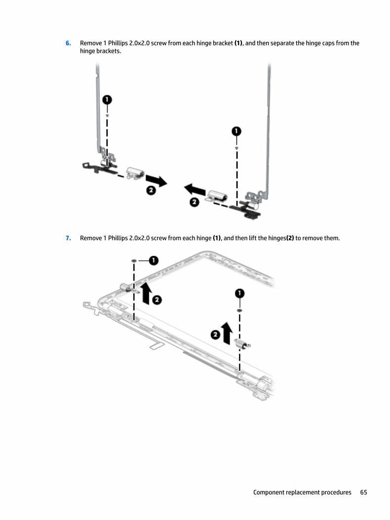
6. Remove 1 Phillips 2.0x2.0 screw from each hinge bracket (1), and then separate the hinge caps from the hinge brackets.
7. Remove 1 Phillips 2.0x2.0 screw from each hinge (1), and then lift the hinges(2) to remove them.
Component replacement procedures 65

8. Remove the WLAN antennas from the back cover (1), release the WLAN cable from the routing channels (2), and then lift the antennas and cable to remove them(3).
Reverse this procedure to install the display assembly.
66 Chapter 5 Removal and replacement procedures for authorized service provider parts

Webcam
Description Spare part number
Webcam
GNRC webcam 1p NM U3 1080p Intel 3D 781624-005
GNRC webcam1p DM U2 Mjpeg 720p VDH2 PA 833962-011
GNRC webcam 1p DM U2 Mjpeg 720p VDH SF 846006-003
IMPORTANT: Make special note of each screw and screw lock size and location during removal and replacement.
Before removing the webcam, follow these steps:
1. Shut down the computer.
2. Disconnect all external devices connected to the computer.
3. Disconnect the power from the computer by first unplugging the power cord from the AC outlet and then unplugging the AC adapter from the computer.
4. Remove the base enclosure (see Base enclosure on page 27), and then remove the following components:
a. Display assembly (see Display assembly on page 29).
b. Hard drive (see Hard drive on page 31).
c. SSD (see SSD (M.2) on page 33).
d. Memory (see Memory on page 34).
e. WLAN module (see WLAN module on page 37).
f. Battery (see Battery on page 39).
g. USB (see USB board on page 42).
h. Power button board (see Power button board on page 43).
i. Fan (see Fan on page 45).
j. Heat sink for discrete graphics (see Heat sink for discrete graphics memory on page 46).
k. Heat sink for CPU and graphics (see Heat sink for CPU and graphics on page 48).
l. System board (see System board on page 53).
m. RTC battery (see RTC battery on page 55).
n. Power connector (see Power connector on page 56).
o. TouchPad (see Power connector on page 56).
p. Display panel (see Display panel on page 61).
Remove the webcam:
▲ Lift the webcam board (1), and then disconnect the webcam cable (2) from the webcam board.
Component replacement procedures 67
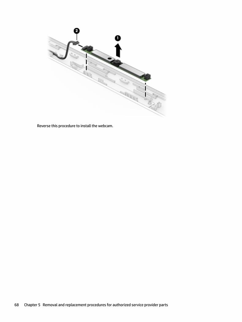
Reverse this procedure to install the webcam.
68 Chapter 5 Removal and replacement procedures for authorized service provider parts

6 Using HP PC Hardware Diagnostics (UEFI)
HP PC Hardware Diagnostics is a Unified Extensible Firmware Interface (UEFI) that allows you to run diagnostic tests to determine whether the computer hardware is functioning properly. The tool runs outside the operating system so that it can isolate hardware failures from issues that are caused by the operating system or other software components.
When HP PC Hardware Diagnostics (UEFI) detects a failure that requires hardware replacement, a 24-digit Failure ID code is generated. This ID code can then be provided to support to help determine how to correct the problem.
NOTE: To start diagnostics on a convertible computer, your computer must be in notebook mode and you must use the keyboard attached.
To start HP PC Hardware Diagnostics (UEFI), follow these steps:
1. Turn on or restart the computer, and quickly press esc.
2. Press f2.
The BIOS searches three places for the diagnostic tools, in the following order:
a. Connected USB drive
NOTE: To download the HP PC Hardware Diagnostics (UEFI) tool to a USB drive, see Downloading HP PC Hardware Diagnostics (UEFI) to a USB device on page 69.
b. Hard drive
c. BIOS
3. When the diagnostic tool opens, select the type of diagnostic test you want to run, and then follow the on-screen instructions.
NOTE: If you need to stop a diagnostic test, press esc.
Downloading HP PC Hardware Diagnostics (UEFI) to a USB deviceNOTE: The HP PC Hardware Diagnostics (UEFI) download instructions are provided in English only, and you must use a Windows computer to download and create the HP UEFI support environment because only .exe files are offered.
There are two options to download HP PC Hardware Diagnostics to a USB device.
Download the latest UEFI version
1. Go to http://www.hp.com/go/techcenter/pcdiags. The HP PC Diagnostics home page is displayed.
2. In the HP PC Hardware Diagnostics section, select the Download link, and then select Run.
Download any version of UEFI for a specific product
1. Go to http://www.hp.com/support.
2. Select Get software and drivers.
Downloading HP PC Hardware Diagnostics (UEFI) to a USB device 69

3. Enter the product name or number.
– or –
Select Identify now to let HP automatically detect your product.
4. Select your computer, and then select your operating system.
5. In the Diagnostic section, follow the on-screen instructions to select and download the UEFI version you want.
70 Chapter 6 Using HP PC Hardware Diagnostics (UEFI)

7 Backing up, restoring, and recovering
This chapter provides information about the following processes. The information in the chapter is standard procedure for most products.
● Creating recovery media and backups
● Restoring and recovering your system
For additional information, refer to the HP support assistant app.
▲ Type support in the taskbar search box, and then select the HP Support Assistant app.
‒ or –
Click the question mark icon in the taskbar.
IMPORTANT: If you will be performing recovery procedures on a tablet, the tablet battery must be at least 70% charged before you start the recovery process.
IMPORTANT: For a tablet with a detachable keyboard, connect the keyboard to the keyboard dock before beginning any recovery process.
Creating recovery media and backupsThe following methods of creating recovery media and backups are available on select products only. Choose the available method according to your computer model.
● Use HP Recovery Manager to create HP Recovery media after you successfully set up the computer. This step creates a backup of the HP Recovery partition on the computer. The backup can be used to reinstall the original operating system in cases where the hard drive is corrupted or has been replaced. For information on creating recovery media, see Creating HP Recovery media (select products only) on page 71. For information on the recovery options that are available using the recovery media, see Using Windows tools on page 72.
● Use Windows tools to create system restore points and create backups of personal information.
For more information, see Recovering using HP Recovery Manager on page 73.
NOTE: If storage is 32 GB or less, Microsoft System Restore is disabled by default.
Creating HP Recovery media (select products only)
If possible, check for the presence of the Recovery partition and the Windows partition. From the Start menu, select File Explorer, and then select This PC.
● If your computer does not list the Windows partition and the Recovery partition, you can obtain recovery media for your system from support. See the Worldwide Telephone Numbers booklet included with the computer. You can also find contact information on the HP website. Go to http://www.hp.com/support, select your country or region, and follow the on-screen instructions.
Creating recovery media and backups 71

You can use Windows tools to create system restore points and create backups of personal information, see Using Windows tools on page 72.
● If your computer does list the Recovery partition and the Windows partition, you can use HP Recovery Manager to create recovery media after you successfully set up the computer. HP Recovery media can be used to perform system recovery if the hard drive becomes corrupted. System recovery reinstalls the original operating system and software programs that were installed at the factory and then configures the settings for the programs. HP Recovery media can also be used to customize the system or restore the factory image if you replace the hard drive.
— Only one set of recovery media can be created. Handle these recovery tools carefully, and keep them in a safe place.
— HP Recovery Manager examines the computer and determines the required storage capacity for the media that will be required.
— To create recovery discs, your computer must have an optical drive with DVD writer capability, and you must use only high-quality blank DVD-R, DVD+R, DVD-R DL, or DVD+R DL discs. Do not use rewritable discs such as CD±RW, DVD±RW, double-layer DVD±RW, or BD-RE (rewritable Blu-ray) discs; they are not compatible with HP Recovery Manager software. Or, instead, you can use a high-quality blank USB flash drive.
— If your computer does not include an integrated optical drive with DVD writer capability, but you would like to create DVD recovery media, you can use an external optical drive (purchased separately) to create recovery discs. If you use an external optical drive, it must be connected directly to a USB port on the computer; the drive cannot be connected to a USB port on an external device, such as a USB hub. If you cannot create DVD media yourself, you can obtain recovery discs for your computer from HP. See the Worldwide Telephone Numbers booklet included with the computer. You can also find contact information on the HP website. Go to http://www.hp.com/support, select your country or region, and follow the on-screen instructions.
— Be sure that the computer is connected to AC power before you begin creating the recovery media.
— The creation process can take an hour or more. Do not interrupt the creation process.
— If necessary, you can exit the program before you have finished creating all of the recovery DVDs. HP Recovery Manager will finish burning the current DVD. The next time you start HP Recovery Manager, you will be prompted to continue.
To create HP Recovery media:
IMPORTANT: For a tablet with a detachable keyboard, connect the keyboard to the keyboard dock before beginning these steps.
1. Type recovery in the taskbar search box, and then select HP Recovery Manager.
2. Select Create recovery media, and then follow the on-screen instructions.
If you ever need to recover the system, see Recovering using HP Recovery Manager on page 73.
Using Windows toolsYou can create recovery media, system restore points, and backups of personal information using Windows tools.
NOTE: If storage is 32 GB or less, Microsoft System Restore is disabled by default.
For more information and steps, see the Get started app.
▲ Select the Start button, and then select the Get started app.
72 Chapter 7 Backing up, restoring, and recovering

Restore and recoveryThere are several options for recovering your system. Choose the method that best matches your situation and level of expertise:
IMPORTANT: Not all methods are available on all products.
● Windows offers several options for restoring from backup, refreshing the computer, and resetting the computer to its original state. For more information see the Get started app.
▲ Select the Start button, and then select the Get started app.
● If you need to correct a problem with a preinstalled application or driver, use the Reinstall drivers and/or applications option (select products only) of HP Recovery Manager to reinstall the individual application or driver.
▲ Type recovery in the taskbar search box, select HP Recovery Manager, select Reinstall drivers and/or applications, and then follow the on-screen instructions.
● If you want to recover the Windows partition to original factory content, you can choose the System Recovery option from the HP Recovery partition (select products only) or use the HP Recovery media. For more information, see Recovering using HP Recovery Manager on page 73. If you have not already created recovery media, see Creating HP Recovery media (select products only) on page 71.
● On select products, if you want to recover the computer's original factory partition and content, or if you have replaced the hard drive, you can use the Factory Reset option of HP Recovery media. For more information, see Recovering using HP Recovery Manager on page 73.
● On select products, if you want to remove the recovery partition to reclaim hard drive space, HP Recovery Manager offers the Remove Recovery Partition option.
For more information, see Removing the HP Recovery partition (select products only) on page 76.
Recovering using HP Recovery Manager
HP Recovery Manager software allows you to recover the computer to its original factory state by using the HP Recovery media that you either created or that you obtained from HP, or by using the HP Recovery partition (select products only). If you have not already created recovery media, see Creating HP Recovery media (select products only) on page 71.
What you need to know before you get started
● HP Recovery Manager recovers only software that was installed at the factory. For software not provided with this computer, you must either download the software from the manufacturer's website or reinstall the software from the media provided by the manufacturer.
IMPORTANT: Recovery through HP Recovery Manager should be used as a final attempt to correct computer issues.
● HP Recovery media must be used if the computer hard drive fails. If you have not already created recovery media, see Creating HP Recovery media (select products only) on page 71.
● To use the Factory Reset option (select products only), you must use HP Recovery media. If you have not already created recovery media, see Creating HP Recovery media (select products only) on page 71.
● If your computer does not allow the creation of HP Recovery media or if the HP Recovery media does not work, you can obtain recovery media for your system from support. See the Worldwide Telephone Numbers booklet included with the computer. You can also find contact information from the HP
Restore and recovery 73

website. Go to http://www.hp.com/support, select your country or region, and follow the on-screen instructions.
IMPORTANT: HP Recovery Manager does not automatically provide backups of your personal data. Before beginning recovery, back up any personal data you want to retain.
Using HP Recovery media, you can choose from one of the following recovery options:
NOTE: Only the options available for your computer display when you start the recovery process.
● System Recovery—Reinstalls the original operating system, and then configures the settings for the programs that were installed at the factory.
● Factory Reset—Restores the computer to its original factory state by deleting all information from the hard drive and re-creating the partitions. Then it reinstalls the operating system and the software that was installed at the factory.
The HP Recovery partition (select products only) allows System Recovery only.
Using the HP Recovery partition (select products only)
The HP Recovery partition allows you to perform a system recovery without the need for recovery discs or a recovery USB flash drive. This type of recovery can be used only if the hard drive is still working.
To start HP Recovery Manager from the HP Recovery partition:
IMPORTANT: For a tablet with a detachable keyboard, connect the keyboard to the keyboard dock before beginning these steps (select products only).
1. Type recovery in the taskbar search box, select Recovery Manager, and then select HP Recovery Environment.
- or-
For computers or tablets with keyboards attached, press f11 while the computer boots, or press and hold f11 as you press the power button.
For tablets without keyboards:
Turn on or restart the tablet, and then quickly hold down the volume down button; then select f11.
- or -
Turn on or restart the tablet, and then quickly hold down the Windows button; then select f11.
2. Select Troubleshoot from the boot options menu.
3. Select Recovery Manager, and then follow the on-screen instructions.
Using HP Recovery media to recover
You can use HP Recovery media to recover the original system. This method can be used if your system does not have an HP Recovery partition or if the hard drive is not working properly.
1. If possible, back up all personal files.
2. Insert the HP Recovery media, and then restart the computer.
NOTE: If the computer does not automatically restart in HP Recovery Manager, change the computer boot order. See Changing the computer boot order on page 75.
3. Follow the on-screen instructions.
74 Chapter 7 Backing up, restoring, and recovering

Changing the computer boot order
If your computer does not restart in HP Recovery Manager, you can change the computer boot order, which is the order of devices listed in BIOS where the computer looks for startup information. You can change the selection to an optical drive or a USB flash drive.
To change the boot order:
IMPORTANT: For a tablet with a detachable keyboard, connect the keyboard to the keyboard dock before beginning these steps.
1. Insert the HP Recovery media.
2. Access BIOS:
For computers or tablets with keyboards attached:
▲ Turn on or restart the computer or tablet, quickly press esc, and then press f9 for boot options.
For tablets without keyboards:
▲ Turn on or restart the tablet, and then quickly hold down the volume down button; then select f9.
- or -
Turn on or restart the tablet, and then quickly hold down the Windows button; then select f9.
3. Select the optical drive or USB flash drive from which you want to boot.
4. Follow the on-screen instructions.
Restore and recovery 75

Removing the HP Recovery partition (select products only)
HP Recovery Manager software allows you to remove the HP Recovery partition to free up hard drive space.
IMPORTANT: After you remove the HP Recovery partition, you will not be able to perform System Recovery or create HP recovery media from the HP Recovery partition. So before you remove the Recovery partition, create HP Recovery media; see Creating HP Recovery media (select products only) on page 71.
NOTE: The Remove Recovery Partition option is only available on products that support this function.
Follow these steps to remove the HP Recovery partition:
1. Type recovery in the taskbar search box, and then select HP Recovery Manager.
2. Select Remove Recovery Partition, and then follow the on-screen instructions.
76 Chapter 7 Backing up, restoring, and recovering

8 Specifications
Computer specifications
Metric U.S.
Dimensions
Width 382.4 mm 15.06 in
Depth 252.5 mm 9.94 in
Height (front to back) 24.5 mm .96 in
Weight 2095 g 4.62 lb
Input power
Operating voltage and current 19.5 V dc @ 2.31 A – 45 W
19.5 V dc @ 3.33 A – 65 W
Temperature
Operating 5°C to 35°C 41°F to 95°F
Nonoperating ‑20°C to 60°C ‑4°F to 140°F
Relative humidity (noncondensing)
Operating 10% to 90%
Nonoperating 5% to 95%
Maximum altitude (unpressurized)
Operating ‑15 m to 3,048 m ‑50 ft to 10,000 ft
Nonoperating ‑15 m to 12,192 m ‑50 ft to 40,000 ft
NOTE: Applicable product safety standards specify thermal limits for plastic surfaces. The device operates well within this range of temperatures.
Computer specifications 77

39.62 cm (15.6-in) display specifications
Metric U.S.
Dimensions
Height 20.77 cm 8.175 in
Width 37.78 cm 14.875 in
Diagonal 39.62 cm 15.6 in
Number of colors Up to 16.8 million
Contrast ratio 500:1 (typical)
Brightness 220, 250, or 300 nits
Pixel resolution
Pitch 0.252mm x 0.252mm
Format 1920x1080 or 3840x2160
Configuration RGB vertical stripe
Backlight LED
Character display 80 × 25
Total power consumption 2.0 W
Viewing angle ±65° horizontal, ±50° vertical (typical)
Hard drive specifications
1 TB* 2TB*
Dimensions
Height 9.5 mm 9.5 mm
Width 69.85 mm 69.85 mm
Weight 102 g max 130 g max
Interface type SATA 3.0 SATA 3.0
Transfer rate 600 MB/sec 600 MB/sec
Security ATA-8 security ATA-8 security
Seek times (typical read, including setting)
Single track 2 ms 2 ms
Average 13.0 ms 12.0 ms
Maximum 15.0 ms 22.0 ms
Logical blocks 1,953,525,168 3,907,029,168
Disk rotational speed 5400 rpm 5400 rpm
Operating temperature 0°C to 60°C (0°F to 140°F) 0°C to 60°C (0°F to 140°F)
78 Chapter 8 Specifications

1 TB* 2TB*
*Size refers to hard drive storage capacity. Actual accessible capacity is less. Actual drive specifications may differ slightly.
NOTE: Certain restrictions and exclusions apply. Contact support for details.
Solid-state drive specifications
Internal Storage*
Supports M.2 SATA-3 SSD
128 GB SATA III Solid-state Drive
256 GB SATA III Solid-state Drive
256 GB SATA III Solid-state Drive NVMe
512 GB SATA III Solid-state Drive NVMe
*For solid-state drives, GB=1 billion bytes. TB=1 trillion bytes. Actual formatted capacity is less. Up to 16 GB (for Windows 7) and up to 30 GB (for Windows 8 and 10) of system disk is reserved for system recovery software.
Solid-state drive specifications 79

9 Power cord set requirements
The wide-range input feature of the computer permits it to operate from any line voltage from 100 to 120 volts AC, or from 220 to 240 volts AC.
The 3-conductor power cord set included with the computer meets the requirements for use in the country or region where the equipment is purchased.
Power cord sets for use in other countries and regions must meet the requirements of the country or region where the computer is used.
Requirements for all countriesThe following requirements are applicable to all countries and regions:
● The length of the power cord set must be at least 1.0 m (3.3 ft) and no more than 2.0 m (6.5 ft).
● All power cord sets must be approved by an acceptable accredited agency responsible for evaluation in the country or region where the power cord set will be used.
● The power cord sets must have a minimum current capacity of 10 amps and a nominal voltage rating of 125 or 250 V AC, as required by the power system of each country or region.
● The appliance coupler must meet the mechanical configuration of an EN 60 320/IEC 320 Standard Sheet C13 connector for mating with the appliance inlet on the back of the computer.
Requirements for specific countries and regions
Country/region Accredited agency Applicable note number
Australia EANSW 1
Austria OVE 1
Belgium CEBC 1
Canada CSA 2
Denmark DEMKO 1
Finland FIMKO 1
France UTE 1
Germany VDE 1
Italy IMQ 1
Japan METI 3
The Netherlands KEMA 1
Norway NEMKO 1
The People's Republic of China COC 5
South Korea EK 4
80 Chapter 9 Power cord set requirements

Country/region Accredited agency Applicable note number
Sweden SEMKO 1
Switzerland SEV 1
Taiwan BSMI 4
The United Kingdom BSI 1
The United States UL 2
1. The flexible cord must be Type HO5VV-F, 3-conductor, 1.0-mm² conductor size. Power cord set fittings (appliance coupler and wall plug) must bear the certification mark of the agency responsible for evaluation in the country or region where it will be used.
2. The flexible cord must be Type SPT-3 or equivalent, No. 18 AWG, 3-conductor. The wall plug must be a two-pole grounding type with a NEMA 5-15P (15 A, 125 V) or NEMA 6-15P (15 A, 250 V) configuration.
3. The appliance coupler, flexible cord, and wall plug must bear a “T” mark and registration number in accordance with the Japanese Dentori Law. The flexible cord must be Type VCT or VCTF, 3-conductor, 1.00-mm² conductor size. The wall plug must be a two-pole grounding type with a Japanese Industrial Standard C8303 (7 A, 125 V) configuration.
4. The flexible cord must be Type RVV, 3-conductor, 0.75-mm² conductor size. Power cord set fittings (appliance coupler and wall plug) must bear the certification mark of the agency responsible for evaluation in the country or region where it will be used.
5. The flexible cord must be Type VCTF, 3-conductor, 0.75-mm² conductor size. Power cord set fittings (appliance coupler and wall plug) must bear the certification mark of the agency responsible for evaluation in the country or region where it will be used.
Requirements for specific countries and regions 81

10 Recycling
When a non-rechargeable or rechargeable battery has reached the end of its useful life, do not dispose of the battery in general household waste. Follow the local laws and regulations in your area for battery disposal.
HP encourages customers to recycle used electronic hardware, HP original print cartridges, and rechargeable batteries. For more information about recycling programs, see the HP Web site at http://www.hp.com/recycle.
82 Chapter 10 Recycling

Index
AAC adapter and battery 5AC adapter, spare part numbers 20action keys 11airplane mode key 12audio, product description 2audio-out (headphone)/audio-in
(microphone) jack, identifying 6
Bback cover
spare part number 20, 61backups 71base enclosure
removal 27spare part number 18
base enclosure, spare part number27
batteryremoval 39spare part number 18, 39
battery cablespare part number 18
bezelspare part number 19, 61
boot orderchanging 75
buttonsleft TouchPad 8power 10right TouchPad 8
Ccamera
identifying 7camera light, identifying 7caps lock light, identifying 9chipset, product description 1components
bottom 12display 7left side 6rear 14right side 5top 8
computer major components 16computer specifications 77connector, power 5
Ddisplay
specifications 78display assembly
removal 29, 61spare part numbers 29, 61subcomponents 19
display cablespare part number 20, 61
Display panelspare part numbers 17
display panelproduct description 1spare part number 61
drive light 5
Eesc key, identifying 11Ethernet, product description 2
Ffan
removal 45spare part number 18spare part numbers 45
fn key, identifying 11
Ggraphics, product description 1
Hhard drive
product description 1removal 31spare part number 18spare part numbers 31specifications 78
HDMI port, identifying 5heat sink
spare part number 18, 46, 48
heat sink for CPU and graphicsremoval 48spare part numbers 48
heat sink for discrete graphics memory
removal 46spare part numbers 46
hinge assemblyspare part number 20, 61
hinge cap assemblyspare part number 20, 61
HP PC Hardware Diagnostics (UEFI)using 69
HP Recovery Managercorrecting boot problems 75starting 74
HP Recovery mediacreating 71recovery 74
HP Recovery partitionrecovery 74removing 76
Iintegrated numeric keypad,
identifying 11internal microphones, identifying 7
Jjacks
audio-out (headphone)/audio-in (microphone) 6
network 5RJ-45 (network) 5
KKeyboard
spare part numbers 17keyboard
product description 3keys
airplane mode 12esc 11fn 11Windows 11
Index 83

Llabels
serial number 14lights
AC adapter and battery light 5caps lock 9drive 5mute 9power 9RJ-45 (network) status 5
Mmechanical requirements, product
description 3memory
removal 34spare part numbers 18, 34
memory card reader, identifying 5memory card, identifying 5memory module
product description 1minimized image recovery 74minimized image, creating 73model name 1mute light, identifying 9
Nnetwork jack, identifying 5
Ooperating system, product
description 3optical drive
product description 2original system recovery 73
Ppointing device, product
description 3ports
HDMI 5product description 2USB 2.0 6USB 3.0 6
power button boardremoval 43spare part number 18spare part numbers 43
power button board cablespare part number 18
power button, identifying 10
power connectorremoval 56spare part number 17spare part numbers 56
power connector, identifying 5power cord
set requirements 80spare part numbers 21
power lights, identifying 9power requirements, product
description 3processor
product description 1product description
audio 2camera 2chipset 1display panel 1Ethernet 2external media cards 2graphics 1hard drive 1keyboard 3mechanical requirements 3memory module 1microphone 2operating system 3optical drive 2pointing device 3ports 2power requirements 3processors 1product name 1security 3serviceability 3wireless 2
product name 1product name and number,
computer 14
Rraw panel
spare part number 19recover
options 73recovery
discs 72, 74HP Recovery Manager 73media 74starting 74
supported discs 72system 73USB flash drive 74using HP Recovery media 72
recovery mediacreating 71creating using HP Recovery
Manager 72recovery partition
removing 76regulatory information 14removal/replacement
procedures 27RJ-45 (network) jack, identifying 5RJ-45 (network) status lights,
identifying 5RTC battery
removal 55spare part number 17spare part numbers 55
Sscrew kit 21security cable slot, identifying 6security, product description 3serial number 14serial number, computer 14serviceability, product description 3slots
memory card reader 5security cable 6
solid-state drivespare part numbers 18specifications 79
speakerremoval 51spare part numbers 51
speakersidentifying 10spare part number 17
specificationscomputer 77display 78hard drive 78solid-state drive 79
SSDremoval 33spare part numbers 33
supported discs, recovery 72
84 Index

system boardremoval 53spare part numbers 18, 53
system informationlocating 14
system recovery 73system restore point
creating 72system restore point, creating 71
TTouchPad
buttons 8removal 58spare part numbers 17, 58
TouchPad zone, identifying 8
UUSB 2.0 port, identifying 6USB 3.0 port 5USB 3.0 port, identifying 6USB board
removal 42spare part number 18spare part numbers 42
USB board cablespare part number 17
USB ports, identifying 5
Vvents, identifying 12, 14
Wwarranty period 14webcam
removal 67spare part number 19spare part numbers 67
webcam cablespare part number 19
Windowssystem restore point 71, 72
Windows key, identifying 11Windows tools
using 72wireless, product description 2WLAN antenna, spare part number
20, 61WLAN antennas, identifying 7WLAN assembly
spare part number 61
WLAN moduleremoval 37spare part number 18spare part numbers 37
Index 85