model 1094b gps substation clock - · pdf filethis manual describes the set up and operation...
TRANSCRIPT

MODEL 1094BGPS SUBSTATION CLOCK
OPERATION MANUAL
ARBITER SYSTEMS, INC.PASO ROBLES, CA 93446U.S.A.WWW.ARBITER.COM
ii
DescriptionThis manual is issued for reference only, at the convenience of Arbiter Systems. Reasonable effortwas made to verify that all contents were accurate as of the time of publication. Check with ArbiterSystems at the address below for any revisions made since the original date of publication.
Contact Information
Arbiter Systems, Inc.1324 Vendels Circle, Suite 121Paso Robles, CA 93446USA(805) 237-3831Website: www.arbiter.commailto:[email protected]:[email protected]
What This Manual CoversThis manual describes the set up and operation of the Model 1094B GPS Substation Clock.
Firmware DatesThis version of the manual is written for clocks having firmware dates of 5 December 2011 or later.Any changes made in subsequent revisions which affect operation or specifications will be noted witheither (a) a new manual or (b) a revised version of this manual. To display the firmware version ordate for your instrument using the 1094 Utility application, see Section 6.6.10. The firmware versionmay also be viewed using “VE” command in a terminal window; see Section 10.3.15, MiscellaneousCommands in Chapter 10.
Firmware UpdatesFirmware updates are available to customers by download from the Arbiter Systems website. Goto www.arbiter.com and select Software Downloads under the Site Navigation (on the left). Then,scroll down to Timing Software and select Model 1094B Software. For service, contact our factoryat Contact Information listed above. Electronic versions of this manual are also available on theArbiter website under Site Navigation, PDF Manuals and Datasheets.

iii
LIMITED WARRANTYArbiter Systems makes no warranty, expressed or implied, on any product manufactured or soldby Arbiter Systems except for the following limited warranty against defects in materials andworkmanship on products manufactured by Arbiter Systems.Clock products manufactured by Arbiter Systems are guaranteed against defective materials andworkmanship under normal use and service from the date of delivery for the period listed asLimited Lifetime.1 The responsibility of Arbiter Systems under this warranty is limited to repairor replacement, at Arbiter Systems’ option, of any product found to be defective. Arbiter Systemsshall have no liability under this warranty unless it receives written notice of any claimed defect.For warranty service or repair, products must be returned to a service facility designated by ArbiterSystems. Buyer shall prepay all shipping charges to Arbiter Systems, and Arbiter Systems shall payshipping charges incurred in returning the product to Buyer. However, Buyer shall pay all shippingcharges, duties and taxes for products returned to Buyer in a country other than the United Statesof America.THE WARRANTY SET FORTH HEREIN CONSTITUTES THE ONLY WARRANTY OBLIGA-TIONS OF ARBITER SYSTEMS, EXPRESSED OR IMPLIED, STATUTORY, BY OPERATIONOF LAW, OR OTHERWISE. ARBITER SYSTEMS DISCLAIMS ANY WARRANTY OF MER-CHANTABILITY OR FITNESS FOR A PARTICULAR PURPOSE, AND BUYER EXPRESSLYWAIVES ALL OTHER WARRANTIES.
This limited warranty does not extend to any product, which has been subject to
1. Improper use or application, abuse, or operation beyond its rated capacity, or contrary to theinstructions in the operation and maintenance manuals (if any);
2. Accident;
3. Repair or maintenance performed by Buyer, except in accordance with the operation andmaintenance manuals, if any, and any special instructions of Arbiter Systems;
4. Modification without the prior written authorization of Arbiter Systems (whether by thesubstitution of non-approved parts or otherwise). The remedies provided herein are Buyer’ssole and exclusive remedies. In no event shall Arbiter Systems be liable for direct, indirect,incidental or consequential damages (including loss of profits), whether based on contract,tort, or other legal theory.
FOR THE FASTEST POSSIBLE SERVICE, PLEASE PROCEED AS FOLLOWS:
1. Notify Arbiter Systems, Inc., specifying the instrument model number and serial number andgiving full details of the difficulty. Service data or instrument-return authorization will beprovided upon receipt of this information.
2. If instrument return is authorized, forward prepaid to the manufacturer. If it is determinedthat the instrument is not covered by this warranty, an estimate will be made before therepair work begins, if requested.
See Contact Information on page ii.
1Limited Lifetime means that Arbiter Systems will repair or replace the defective component as long as componentsare available and for no more than five years after the product has been deemed obsolete.

iv

v
Model 1094B
GPS Substation Clock
Operation Manual
Chapter 1 Unpacking the Clock
Chapter 2 Front and Rear Panels
Chapter 3 Connecting Inlet Power
Chapter 4 Antenna and Cable Information
Chapter 5 Setting Internal Jumpers
Chapter 6 Startup and Application Software
Chapter 7 The Setup Menus
Chapter 8 Timing, IRIG-B, and Pulses
Chapter 9 Relay Contacts and Event Inputs
Chapter 10 Serial Communication and Commands
Appendix A Technical Details and Specifications
Appendix B Using Surge Arresters
Appendix C Statement of Compliance
Appendix D Switching High Voltage Signal Lines
Index
Copyright Arbiter Systems Incorporated August 2017. All rights reserved. International copyrightsecured.
PD0036600T

Contents
1 Unpacking the Clock 1
1.1 Introduction . . . . . . . . . . . . . . . . . . . . . . . . . . . . . . . . . . . . . . . . . 1
1.2 Precautions . . . . . . . . . . . . . . . . . . . . . . . . . . . . . . . . . . . . . . . . . 1
1.3 Unpacking and Locating Accessories . . . . . . . . . . . . . . . . . . . . . . . . . . . 2
1.4 Attaching Rack-Mount Ears to Clock . . . . . . . . . . . . . . . . . . . . . . . . . . . 2
1.4.1 Mounting Instructions . . . . . . . . . . . . . . . . . . . . . . . . . . . . . . . 3
1.5 Mounting Antenna and Antenna Cable . . . . . . . . . . . . . . . . . . . . . . . . . . 3
2 Front and Rear Panels 4
2.1 Introduction . . . . . . . . . . . . . . . . . . . . . . . . . . . . . . . . . . . . . . . . . 4
2.2 Front Panel Controls and Indicators . . . . . . . . . . . . . . . . . . . . . . . . . . . 4
2.2.1 Annunciator LED Definitions . . . . . . . . . . . . . . . . . . . . . . . . . . . 5
2.2.2 LCD Display . . . . . . . . . . . . . . . . . . . . . . . . . . . . . . . . . . . . 5
2.2.3 Command Key Definitions . . . . . . . . . . . . . . . . . . . . . . . . . . . . . 6
2.3 Rear Panel Identification and Connectors . . . . . . . . . . . . . . . . . . . . . . . . 7
2.3.1 Power Inlet . . . . . . . . . . . . . . . . . . . . . . . . . . . . . . . . . . . . . 7
2.3.2 Antenna Input . . . . . . . . . . . . . . . . . . . . . . . . . . . . . . . . . . . 8
2.3.3 Event Input . . . . . . . . . . . . . . . . . . . . . . . . . . . . . . . . . . . . . 9
2.3.4 RS-232 and RS-485 Communication Ports . . . . . . . . . . . . . . . . . . . . 9
2.3.5 Form C Relay Contacts . . . . . . . . . . . . . . . . . . . . . . . . . . . . . . 9
2.3.6 Timing Outputs . . . . . . . . . . . . . . . . . . . . . . . . . . . . . . . . . . 10
3 Connecting Inlet Power 11
3.1 Option 07, IEC-320 Power Inlet Module . . . . . . . . . . . . . . . . . . . . . . . . . 11
3.1.1 Cordsets and Plug Styles for Option 07 . . . . . . . . . . . . . . . . . . . . . 12
3.1.2 Option 07, Connecting Power to the 1094B . . . . . . . . . . . . . . . . . . . 12
3.2 Option 08, 10 to 60 Vdc Power Inlet Module . . . . . . . . . . . . . . . . . . . . . . 12
3.2.1 Option 08, Connecting Inlet Power . . . . . . . . . . . . . . . . . . . . . . . . 13
3.3 Option 10, 110 to 350 Vdc Terminal Power Strip, Surge Withstand . . . . . . . . . . 13
3.3.1 Option 10, Connecting Inlet Power . . . . . . . . . . . . . . . . . . . . . . . . 13
3.4 Fuse Locations and Types . . . . . . . . . . . . . . . . . . . . . . . . . . . . . . . . . 13
3.4.1 Replacing Fuses . . . . . . . . . . . . . . . . . . . . . . . . . . . . . . . . . . . 14
4 GPS Antenna and Cable Information 15
4.1 GPS Antenna Installation . . . . . . . . . . . . . . . . . . . . . . . . . . . . . . . . . 15
4.1.1 Mounting the Antenna . . . . . . . . . . . . . . . . . . . . . . . . . . . . . . . 15
CONTENTS vii
4.1.2 Optional Antenna Mounting Kit, P/N AS0044600 . . . . . . . . . . . . . . . 16
4.2 Verifying Antenna and Cable Operation . . . . . . . . . . . . . . . . . . . . . . . . . 18
4.2.1 GPS Signal Strength . . . . . . . . . . . . . . . . . . . . . . . . . . . . . . . . 18
4.2.2 Checking the Antenna Voltage . . . . . . . . . . . . . . . . . . . . . . . . . . 18
4.2.3 Power Supply Check . . . . . . . . . . . . . . . . . . . . . . . . . . . . . . . . 18
4.2.4 Checking the Antenna Resistance . . . . . . . . . . . . . . . . . . . . . . . . . 18
4.3 GPS Surge Arrester . . . . . . . . . . . . . . . . . . . . . . . . . . . . . . . . . . . . 18
4.3.1 Using the GPS Surge Arrester . . . . . . . . . . . . . . . . . . . . . . . . . . 19
4.4 Technical Details on GPS, Antennas and Cables . . . . . . . . . . . . . . . . . . . . 19
4.4.1 Antenna Cable . . . . . . . . . . . . . . . . . . . . . . . . . . . . . . . . . . . 19
5 Setting Internal Jumpers 22
5.1 Introduction . . . . . . . . . . . . . . . . . . . . . . . . . . . . . . . . . . . . . . . . . 22
5.1.1 Jumper Locations . . . . . . . . . . . . . . . . . . . . . . . . . . . . . . . . . 22
5.1.2 List of Default Jumper Positions and Functions . . . . . . . . . . . . . . . . . 23
5.2 Configuring Output Jumpers . . . . . . . . . . . . . . . . . . . . . . . . . . . . . . . 23
5.2.1 Configuration Notes . . . . . . . . . . . . . . . . . . . . . . . . . . . . . . . . 24
5.3 Configuring Relay Mode Jumpers . . . . . . . . . . . . . . . . . . . . . . . . . . . . . 24
5.3.1 Relay Contact Specifications . . . . . . . . . . . . . . . . . . . . . . . . . . . 25
5.4 Configuring Communication Port Jumpers . . . . . . . . . . . . . . . . . . . . . . . . 25
5.5 Configuring Event Input Jumpers . . . . . . . . . . . . . . . . . . . . . . . . . . . . . 26
5.5.1 Selecting the Event Input Channel and Voltage . . . . . . . . . . . . . . . . . 26
5.5.2 Configuring the Event/1-PPS Function . . . . . . . . . . . . . . . . . . . . . 26
6 Clock Startup and Utility Software 27
6.1 Initial Startup Sequence . . . . . . . . . . . . . . . . . . . . . . . . . . . . . . . . . . 27
6.1.1 Clock Time, Startup Mode . . . . . . . . . . . . . . . . . . . . . . . . . . . . 27
6.2 Front Panel Indication . . . . . . . . . . . . . . . . . . . . . . . . . . . . . . . . . . . 28
6.2.1 LCD Display Indication at Startup . . . . . . . . . . . . . . . . . . . . . . . . 28
6.2.2 Other Display Indications When Unlocked . . . . . . . . . . . . . . . . . . . . 28
6.2.3 Status Display Indications . . . . . . . . . . . . . . . . . . . . . . . . . . . . . 29
6.2.4 Event/Deviation Display . . . . . . . . . . . . . . . . . . . . . . . . . . . . . . 29
6.2.5 IRIG-B Time Data . . . . . . . . . . . . . . . . . . . . . . . . . . . . . . . . . 30
6.3 Clock Status Display Mode . . . . . . . . . . . . . . . . . . . . . . . . . . . . . . . . 30
6.4 Time Display Modes . . . . . . . . . . . . . . . . . . . . . . . . . . . . . . . . . . . . 30
6.4.1 Date and Time Display, Universal Time Coordinated (UTC) . . . . . . . . . 30
6.4.2 Time of Year Display, Universal Time Coordinated, (UTC) . . . . . . . . . . 31
6.4.3 Date and Time Display, Local Time . . . . . . . . . . . . . . . . . . . . . . . 31
6.4.4 Time of Year Display, Local Time . . . . . . . . . . . . . . . . . . . . . . . . 31
6.4.5 Daylight Saving-Summer Time . . . . . . . . . . . . . . . . . . . . . . . . . . 32
6.5 Position Display Modes . . . . . . . . . . . . . . . . . . . . . . . . . . . . . . . . . . 32
6.5.1 Longitude Display . . . . . . . . . . . . . . . . . . . . . . . . . . . . . . . . . 32
6.5.2 Latitude Display . . . . . . . . . . . . . . . . . . . . . . . . . . . . . . . . . . 32
6.5.3 Elevation Display . . . . . . . . . . . . . . . . . . . . . . . . . . . . . . . . . . 32
6.6 Application Software – 1094B Utility . . . . . . . . . . . . . . . . . . . . . . . . . . . 33
6.6.1 Configuring with 1094B Utility Software . . . . . . . . . . . . . . . . . . . . . 33

viii CONTENTS
6.6.2 Establishing a Serial Connection . . . . . . . . . . . . . . . . . . . . . . . . . 34
6.6.3 Reading Clock Configuration . . . . . . . . . . . . . . . . . . . . . . . . . . . 36
6.6.4 The System Screen . . . . . . . . . . . . . . . . . . . . . . . . . . . . . . . . . 37
6.6.5 The Communication Screen . . . . . . . . . . . . . . . . . . . . . . . . . . . . 39
6.6.6 The Time Screen . . . . . . . . . . . . . . . . . . . . . . . . . . . . . . . . . . 40
6.6.7 The IRIG-B Screen . . . . . . . . . . . . . . . . . . . . . . . . . . . . . . . . . 41
6.6.8 The Programmable Pulse A Screen . . . . . . . . . . . . . . . . . . . . . . . . 42
6.6.9 The Programmable Pulse B Screen . . . . . . . . . . . . . . . . . . . . . . . . 43
6.6.10 The Version Screen . . . . . . . . . . . . . . . . . . . . . . . . . . . . . . . . . 44
6.6.11 Setting to Factory Defaults . . . . . . . . . . . . . . . . . . . . . . . . . . . . 44
6.6.12 Saving a Configuration File . . . . . . . . . . . . . . . . . . . . . . . . . . . . 45
6.6.13 Opening a New Configuration . . . . . . . . . . . . . . . . . . . . . . . . . . . 45
6.7 Uploading New Firmware using the 109x Loader . . . . . . . . . . . . . . . . . . . . . 45
6.7.1 Using the Uploader . . . . . . . . . . . . . . . . . . . . . . . . . . . . . . . . . 45
7 The Setup Menus 47
7.1 Setup Menus . . . . . . . . . . . . . . . . . . . . . . . . . . . . . . . . . . . . . . . . 47
7.1.1 To Begin Configuring . . . . . . . . . . . . . . . . . . . . . . . . . . . . . . . 48
7.1.2 Numeric Data Entry Mode . . . . . . . . . . . . . . . . . . . . . . . . . . . . 48
7.1.3 Default Firmware Settings . . . . . . . . . . . . . . . . . . . . . . . . . . . . . 48
7.1.4 To Exit Setup Menus . . . . . . . . . . . . . . . . . . . . . . . . . . . . . . . 48
7.2 Set Serial COM1 . . . . . . . . . . . . . . . . . . . . . . . . . . . . . . . . . . . . . . 49
7.3 Set Serial COM2 . . . . . . . . . . . . . . . . . . . . . . . . . . . . . . . . . . . . . . 49
7.3.1 Set Broadcast Mode from Serial COM1 . . . . . . . . . . . . . . . . . . . . . 50
7.3.2 Configure Serial COM1 Port Parameters . . . . . . . . . . . . . . . . . . . . . 51
7.4 Set Local Offset . . . . . . . . . . . . . . . . . . . . . . . . . . . . . . . . . . . . . . . 51
7.5 Set DST/Summer Time . . . . . . . . . . . . . . . . . . . . . . . . . . . . . . . . . . 52
7.6 Set Out of Lock . . . . . . . . . . . . . . . . . . . . . . . . . . . . . . . . . . . . . . . 53
7.7 Set Backlight . . . . . . . . . . . . . . . . . . . . . . . . . . . . . . . . . . . . . . . . 53
7.8 Set Cable Delay . . . . . . . . . . . . . . . . . . . . . . . . . . . . . . . . . . . . . . . 54
7.9 Set Programmable Pulse A and B . . . . . . . . . . . . . . . . . . . . . . . . . . . . 55
7.9.1 Programmable Pulse A . . . . . . . . . . . . . . . . . . . . . . . . . . . . . . 55
7.9.2 Programmable Pulse B . . . . . . . . . . . . . . . . . . . . . . . . . . . . . . 55
7.9.3 Programmable Pulse Signal Levels . . . . . . . . . . . . . . . . . . . . . . . . 55
7.9.4 Programmable Pulse A or B Preliminary Setup . . . . . . . . . . . . . . . . . 56
7.9.5 Setting the Pulse-Per-Second Mode . . . . . . . . . . . . . . . . . . . . . . . . 56
7.9.6 Setting the Pulse-Per-Minute Mode . . . . . . . . . . . . . . . . . . . . . . . 57
7.9.7 Setting the Pulse-Per-Hour Mode . . . . . . . . . . . . . . . . . . . . . . . . . 57
7.9.8 Setting the Pulse-Per-Day Mode . . . . . . . . . . . . . . . . . . . . . . . . . 58
7.9.9 Setting the Single-Trigger Mode . . . . . . . . . . . . . . . . . . . . . . . . . 58
7.9.10 Setting the Slow-Code Mode . . . . . . . . . . . . . . . . . . . . . . . . . . . 59
7.9.11 Setting the Seconds-Per-Pulse Mode . . . . . . . . . . . . . . . . . . . . . . . 59
7.9.12 Setting the Frequency Mode, Programmable Pulse B . . . . . . . . . . . . . . 60
7.9.13 Setting the Aux IRIG Mode, Programmable Pulse B . . . . . . . . . . . . . . 60
7.10 Set IRIG-B Main . . . . . . . . . . . . . . . . . . . . . . . . . . . . . . . . . . . . . . 61
7.11 Set Auto Survey . . . . . . . . . . . . . . . . . . . . . . . . . . . . . . . . . . . . . . 62

CONTENTS ix
7.12 Set Event/Deviation . . . . . . . . . . . . . . . . . . . . . . . . . . . . . . . . . . . . 63
7.12.1 Technical Details of Event/Deviation Timing . . . . . . . . . . . . . . . . . . 63
8 Timing, IRIG-B and Pulses 64
8.1 Introduction . . . . . . . . . . . . . . . . . . . . . . . . . . . . . . . . . . . . . . . . . 64
8.2 Timing Output Description . . . . . . . . . . . . . . . . . . . . . . . . . . . . . . . . 64
8.2.1 Standard Inputs and Outputs . . . . . . . . . . . . . . . . . . . . . . . . . . . 64
8.2.2 Digital Drivers – 250 mA Per Channel . . . . . . . . . . . . . . . . . . . . . . 65
8.2.3 Analog Drivers . . . . . . . . . . . . . . . . . . . . . . . . . . . . . . . . . . . 65
8.3 Output Signal Description . . . . . . . . . . . . . . . . . . . . . . . . . . . . . . . . . 66
8.3.1 IRIG-B Description . . . . . . . . . . . . . . . . . . . . . . . . . . . . . . . . 66
8.3.2 Modulated and Unmodulated IRIG-B . . . . . . . . . . . . . . . . . . . . . . 67
8.3.3 IRIG-B IEEE 1344 Extension . . . . . . . . . . . . . . . . . . . . . . . . . . . 67
8.3.4 1 Pulse per Second (1 PPS) . . . . . . . . . . . . . . . . . . . . . . . . . . . . 67
8.3.5 Programmable Pulse (Prog. Pulse) . . . . . . . . . . . . . . . . . . . . . . . . 68
8.3.6 Programmable Pulse with 300-Volt FET, Setup . . . . . . . . . . . . . . . . . 68
8.3.7 300-Volt FET Connection – Setup and Protection . . . . . . . . . . . . . . . 68
8.4 Connecting Outputs . . . . . . . . . . . . . . . . . . . . . . . . . . . . . . . . . . . . 69
8.4.1 Attaching Cables to Screw Terminals . . . . . . . . . . . . . . . . . . . . . . . 69
8.4.2 How Far Can I Run IRIG-B Cabling? . . . . . . . . . . . . . . . . . . . . . . 69
8.4.3 Synchronizing Multiple Devices From One Masterclock Output . . . . . . . . 69
8.4.4 Connecting Unmodulated IRIG-B . . . . . . . . . . . . . . . . . . . . . . . . 70
8.4.5 Connecting Modulated IRIG-B . . . . . . . . . . . . . . . . . . . . . . . . . . 70
8.4.6 Wire Losses . . . . . . . . . . . . . . . . . . . . . . . . . . . . . . . . . . . . . 71
8.4.7 Voltage Matching for Modulated IRIG-B . . . . . . . . . . . . . . . . . . . . 71
8.4.8 Cable Delays . . . . . . . . . . . . . . . . . . . . . . . . . . . . . . . . . . . . 71
8.4.9 Solutions . . . . . . . . . . . . . . . . . . . . . . . . . . . . . . . . . . . . . . 72
9 Relay Contacts and Event Inputs 73
9.1 Introduction to Relay Operation . . . . . . . . . . . . . . . . . . . . . . . . . . . . . 73
9.2 Configuring . . . . . . . . . . . . . . . . . . . . . . . . . . . . . . . . . . . . . . . . . 73
9.3 Fault Conditions . . . . . . . . . . . . . . . . . . . . . . . . . . . . . . . . . . . . . . 73
9.4 Viewing the Fault Status . . . . . . . . . . . . . . . . . . . . . . . . . . . . . . . . . 73
9.5 Connecting to the Multimode Relay . . . . . . . . . . . . . . . . . . . . . . . . . . . 74
9.5.1 Relay Contact Operation . . . . . . . . . . . . . . . . . . . . . . . . . . . . . 74
9.6 Introduction to Event Inputs . . . . . . . . . . . . . . . . . . . . . . . . . . . . . . . 74
9.7 Event Timing Inputs . . . . . . . . . . . . . . . . . . . . . . . . . . . . . . . . . . . . 74
9.7.1 Event Timing – Latency . . . . . . . . . . . . . . . . . . . . . . . . . . . . . . 74
9.7.2 Deviation Measurement . . . . . . . . . . . . . . . . . . . . . . . . . . . . . . 75
9.7.3 Measurement Principle . . . . . . . . . . . . . . . . . . . . . . . . . . . . . . . 75
9.7.4 Event Timer Input Channel Configuration . . . . . . . . . . . . . . . . . . . . 75
9.7.5 Configuring Event/Deviation Operation . . . . . . . . . . . . . . . . . . . . . 75
9.7.6 Accessing or Displaying Event Data . . . . . . . . . . . . . . . . . . . . . . . 76
9.7.7 Clearing Events . . . . . . . . . . . . . . . . . . . . . . . . . . . . . . . . . . . 77

x CONTENTS
10 Serial Communication and Commands 79
10.1 Introduction . . . . . . . . . . . . . . . . . . . . . . . . . . . . . . . . . . . . . . . . . 79
10.2 Communication Port Information . . . . . . . . . . . . . . . . . . . . . . . . . . . . . 79
10.3 Command Set . . . . . . . . . . . . . . . . . . . . . . . . . . . . . . . . . . . . . . . . 80
10.3.1 Configuring Custom Broadcast Strings . . . . . . . . . . . . . . . . . . . . . . 80
10.3.2 Broadcast Mode Overview . . . . . . . . . . . . . . . . . . . . . . . . . . . . . 83
10.3.3 COM Port Settings . . . . . . . . . . . . . . . . . . . . . . . . . . . . . . . . . 83
10.3.4 Broadcast Commands . . . . . . . . . . . . . . . . . . . . . . . . . . . . . . . 84
10.3.5 Event Mode Commands . . . . . . . . . . . . . . . . . . . . . . . . . . . . . . 90
10.3.6 Status Mode Commands . . . . . . . . . . . . . . . . . . . . . . . . . . . . . . 91
10.3.7 Local / Daylight Saving Time Setup Commands . . . . . . . . . . . . . . . . 92
10.3.8 Front Panel Control Commands . . . . . . . . . . . . . . . . . . . . . . . . . 93
10.3.9 IRIG-B Data Output Commands . . . . . . . . . . . . . . . . . . . . . . . . . 94
10.3.10 Position Data Commands . . . . . . . . . . . . . . . . . . . . . . . . . . . . . 94
10.3.11 Date and Time Commands . . . . . . . . . . . . . . . . . . . . . . . . . . . . 95
10.3.12 Programmable Pulse Output Commands . . . . . . . . . . . . . . . . . . . . . 96
10.3.13 Antenna System Delay Commands . . . . . . . . . . . . . . . . . . . . . . . . 98
10.3.14 Out-of-Lock Commands . . . . . . . . . . . . . . . . . . . . . . . . . . . . . . 98
10.3.15 Miscellaneous Commands . . . . . . . . . . . . . . . . . . . . . . . . . . . . . 98
A Technical Specifications and Operating Parameters 100
A.1 Introduction . . . . . . . . . . . . . . . . . . . . . . . . . . . . . . . . . . . . . . . . . 100
A.2 Receiver Characteristics . . . . . . . . . . . . . . . . . . . . . . . . . . . . . . . . . . 100
A.2.1 Input Signal Type & Frequency . . . . . . . . . . . . . . . . . . . . . . . . . . 100
A.2.2 Timing Accuracy . . . . . . . . . . . . . . . . . . . . . . . . . . . . . . . . . . 100
A.2.3 Internal Oscillator . . . . . . . . . . . . . . . . . . . . . . . . . . . . . . . . . 100
A.2.4 Position Accuracy . . . . . . . . . . . . . . . . . . . . . . . . . . . . . . . . . 100
A.2.5 Satellite Tracking . . . . . . . . . . . . . . . . . . . . . . . . . . . . . . . . . . 100
A.2.6 Acquisition . . . . . . . . . . . . . . . . . . . . . . . . . . . . . . . . . . . . . 101
A.3 I/O Configuration . . . . . . . . . . . . . . . . . . . . . . . . . . . . . . . . . . . . . 101
A.3.1 Timed Outputs . . . . . . . . . . . . . . . . . . . . . . . . . . . . . . . . . . . 101
A.3.2 I/O Connectors . . . . . . . . . . . . . . . . . . . . . . . . . . . . . . . . . . . 101
A.3.3 Standard Output Signals . . . . . . . . . . . . . . . . . . . . . . . . . . . . . 101
A.3.4 Input Functions . . . . . . . . . . . . . . . . . . . . . . . . . . . . . . . . . . . 101
A.3.5 Event Input Timing . . . . . . . . . . . . . . . . . . . . . . . . . . . . . . . . 101
A.4 SPDT Relay Specifications . . . . . . . . . . . . . . . . . . . . . . . . . . . . . . . . 102
A.5 Systems Interface . . . . . . . . . . . . . . . . . . . . . . . . . . . . . . . . . . . . . . 102
A.5.1 RS-232C COM1 and COM2 . . . . . . . . . . . . . . . . . . . . . . . . . . . . 102
A.5.2 Communication Parameters . . . . . . . . . . . . . . . . . . . . . . . . . . . . 102
A.5.3 Broadcast Data Formats . . . . . . . . . . . . . . . . . . . . . . . . . . . . . . 102
A.5.4 Antenna System . . . . . . . . . . . . . . . . . . . . . . . . . . . . . . . . . . 102
A.5.5 Antenna Cable . . . . . . . . . . . . . . . . . . . . . . . . . . . . . . . . . . . 103
A.5.6 Operator Interface . . . . . . . . . . . . . . . . . . . . . . . . . . . . . . . . . 103
A.5.7 Setup Functions . . . . . . . . . . . . . . . . . . . . . . . . . . . . . . . . . . 103
A.5.8 Display . . . . . . . . . . . . . . . . . . . . . . . . . . . . . . . . . . . . . . . 103
A.5.9 Display Functions . . . . . . . . . . . . . . . . . . . . . . . . . . . . . . . . . 103

CONTENTS xi
A.5.10 Annunciators - LEDs . . . . . . . . . . . . . . . . . . . . . . . . . . . . . . . . 103A.6 Physical Specifications . . . . . . . . . . . . . . . . . . . . . . . . . . . . . . . . . . . 103
A.6.1 Dimensions . . . . . . . . . . . . . . . . . . . . . . . . . . . . . . . . . . . . . 103A.6.2 Weight . . . . . . . . . . . . . . . . . . . . . . . . . . . . . . . . . . . . . . . . 104A.6.3 Power Requirements . . . . . . . . . . . . . . . . . . . . . . . . . . . . . . . . 104A.6.4 Power Connector . . . . . . . . . . . . . . . . . . . . . . . . . . . . . . . . . . 104A.6.5 Electromagnetic Interference . . . . . . . . . . . . . . . . . . . . . . . . . . . 104A.6.6 Temperature and Humidity . . . . . . . . . . . . . . . . . . . . . . . . . . . . 104
B Using a Surge Arrester 105B.1 Introduction . . . . . . . . . . . . . . . . . . . . . . . . . . . . . . . . . . . . . . . . . 105B.2 Description . . . . . . . . . . . . . . . . . . . . . . . . . . . . . . . . . . . . . . . . . 105B.3 Installation . . . . . . . . . . . . . . . . . . . . . . . . . . . . . . . . . . . . . . . . . 105
B.3.1 Mounting Location . . . . . . . . . . . . . . . . . . . . . . . . . . . . . . . . . 105B.3.2 Ground Connection . . . . . . . . . . . . . . . . . . . . . . . . . . . . . . . . 105B.3.3 Antenna and Clock Connections . . . . . . . . . . . . . . . . . . . . . . . . . 106B.3.4 Weather Sealing the Connections . . . . . . . . . . . . . . . . . . . . . . . . . 106B.3.5 Suggested Mounting . . . . . . . . . . . . . . . . . . . . . . . . . . . . . . . . 106
B.4 Physical Dimensions . . . . . . . . . . . . . . . . . . . . . . . . . . . . . . . . . . . . 106
C Statement of Compliance 108C.1 Introduction . . . . . . . . . . . . . . . . . . . . . . . . . . . . . . . . . . . . . . . . . 108
D Switching High Voltage Signals 110D.1 Introduction . . . . . . . . . . . . . . . . . . . . . . . . . . . . . . . . . . . . . . . . . 110D.2 Example 1: 300-Volt FET Pull Down . . . . . . . . . . . . . . . . . . . . . . . . . . . 110
D.2.1 Logging Requirements and Circuit Notes . . . . . . . . . . . . . . . . . . . . 111D.3 Example 2: 300-Volt FET with Voltage Source in Series . . . . . . . . . . . . . . . . 111
D.3.1 Logging Requirements and Circuit Notes . . . . . . . . . . . . . . . . . . . . 111D.3.2 Configuring for 300-Volt FET Pull Down . . . . . . . . . . . . . . . . . . . . 111
D.4 Example 3: 5 Volt Switching with External Relay . . . . . . . . . . . . . . . . . . . . 112D.4.1 Configuring for 5-Volt CMOS . . . . . . . . . . . . . . . . . . . . . . . . . . . 112

List of Figures
1.1 Packaging of Accessories . . . . . . . . . . . . . . . . . . . . . . . . . . . . . . . . . . 2
1.2 Attaching Rack-Mount Ears . . . . . . . . . . . . . . . . . . . . . . . . . . . . . . . . 3
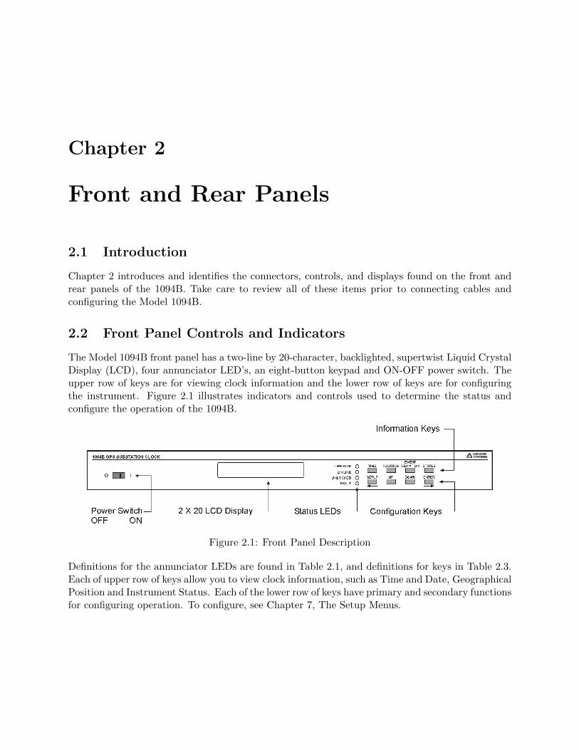
2.1 Front Panel Description . . . . . . . . . . . . . . . . . . . . . . . . . . . . . . . . . . 4
2.2 Rear Panel Description . . . . . . . . . . . . . . . . . . . . . . . . . . . . . . . . . . . 7
2.3 Option 07 Power Supply . . . . . . . . . . . . . . . . . . . . . . . . . . . . . . . . . . 7
2.4 Option 08 Power Supply . . . . . . . . . . . . . . . . . . . . . . . . . . . . . . . . . . 8
2.5 Option 10 Power Supply . . . . . . . . . . . . . . . . . . . . . . . . . . . . . . . . . . 8
2.6 GPS Antenna Connector . . . . . . . . . . . . . . . . . . . . . . . . . . . . . . . . . . 8
2.7 Event Input Connector . . . . . . . . . . . . . . . . . . . . . . . . . . . . . . . . . . . 9
2.8 Communication Port Connectors . . . . . . . . . . . . . . . . . . . . . . . . . . . . . 9
2.9 Relay Contact Connectors . . . . . . . . . . . . . . . . . . . . . . . . . . . . . . . . . 9
2.10 Timing Connectors, IRIG-B and Pulse . . . . . . . . . . . . . . . . . . . . . . . . . . 10
3.1 Option 07 Power Supply Inlet Description . . . . . . . . . . . . . . . . . . . . . . . . 11
3.2 Option 08 Power Supply Inlet Description . . . . . . . . . . . . . . . . . . . . . . . . 12
3.3 Option 10 Power Supply Inlet Description . . . . . . . . . . . . . . . . . . . . . . . . 13
4.1 Antenna Assembly for Mounting . . . . . . . . . . . . . . . . . . . . . . . . . . . . . 16
4.2 Antenna Mounting Bracket . . . . . . . . . . . . . . . . . . . . . . . . . . . . . . . . 17
4.3 Antenna Mounting with AS0044600 . . . . . . . . . . . . . . . . . . . . . . . . . . . 17
4.4 GPS Surge Arrester . . . . . . . . . . . . . . . . . . . . . . . . . . . . . . . . . . . . 18
5.1 Mainboard Jumper Locations . . . . . . . . . . . . . . . . . . . . . . . . . . . . . . . 22
6.1 1094B Utility Software, Opening Window . . . . . . . . . . . . . . . . . . . . . . . . 33
6.2 Connecting with the 1094B . . . . . . . . . . . . . . . . . . . . . . . . . . . . . . . . 34
6.3 Windows XP Device Manager – identify COM port . . . . . . . . . . . . . . . . . . . 35
6.4 COM Port Assignment, Windows XP . . . . . . . . . . . . . . . . . . . . . . . . . . 35
6.5 Reading the 1094B Configuration . . . . . . . . . . . . . . . . . . . . . . . . . . . . . 36
6.6 Reading the 1094B, System Screen . . . . . . . . . . . . . . . . . . . . . . . . . . . . 37
6.7 Clearing Events in the 1094B . . . . . . . . . . . . . . . . . . . . . . . . . . . . . . . 38
6.8 Communication Settings Screen . . . . . . . . . . . . . . . . . . . . . . . . . . . . . . 39
6.9 Time Adjustment Screen . . . . . . . . . . . . . . . . . . . . . . . . . . . . . . . . . . 40
6.10 IRIG-B Adjustment Screen . . . . . . . . . . . . . . . . . . . . . . . . . . . . . . . . 41
6.11 Programmable Pulse A Setup Screen . . . . . . . . . . . . . . . . . . . . . . . . . . . 42
6.12 Programmable Pulse B Setup Screen . . . . . . . . . . . . . . . . . . . . . . . . . . . 43
LIST OF FIGURES xiii
6.13 1094B Version Display Screen . . . . . . . . . . . . . . . . . . . . . . . . . . . . . . . 446.14 1094B Loader with Opened Firmware File . . . . . . . . . . . . . . . . . . . . . . . . 466.15 Successful Upload of New Firmware . . . . . . . . . . . . . . . . . . . . . . . . . . . 46
7.1 COM1 Setup . . . . . . . . . . . . . . . . . . . . . . . . . . . . . . . . . . . . . . . . 497.2 COM2 Setup . . . . . . . . . . . . . . . . . . . . . . . . . . . . . . . . . . . . . . . . 497.3 Broadcast Mode Setup . . . . . . . . . . . . . . . . . . . . . . . . . . . . . . . . . . . 507.4 COM1 and COM2 Parameter Setup . . . . . . . . . . . . . . . . . . . . . . . . . . . 517.5 Local Time Setup . . . . . . . . . . . . . . . . . . . . . . . . . . . . . . . . . . . . . . 517.6 Daylight Saving and Summer Time Setup . . . . . . . . . . . . . . . . . . . . . . . . 527.7 Out-of-Lock Time Setup . . . . . . . . . . . . . . . . . . . . . . . . . . . . . . . . . . 537.8 Backlight Setup . . . . . . . . . . . . . . . . . . . . . . . . . . . . . . . . . . . . . . . 537.9 Cable Delay Setup . . . . . . . . . . . . . . . . . . . . . . . . . . . . . . . . . . . . . 547.10 Programmable Pulse Setup, Preliminary Information . . . . . . . . . . . . . . . . . . 567.11 Programmable Pulse Setup, Pulse Per Second . . . . . . . . . . . . . . . . . . . . . . 567.12 Programmable Pulse Setup, Pulse Per Minute . . . . . . . . . . . . . . . . . . . . . . 577.13 Programmable Pulse Setup, Pulse Per Hour . . . . . . . . . . . . . . . . . . . . . . . 577.14 Programmable Pulse Setup, Pulse-Per-Day Mode . . . . . . . . . . . . . . . . . . . . 587.15 Programmable Pulse Setup, Single-Trigger Mode . . . . . . . . . . . . . . . . . . . . 587.16 Programmable Pulse Setup, Slow-Code Mode . . . . . . . . . . . . . . . . . . . . . . 597.17 Programmable Pulse Setup, Seconds-Per-Pulse Mode . . . . . . . . . . . . . . . . . . 597.18 Programmable Pulse Setup, Frequency Mode . . . . . . . . . . . . . . . . . . . . . . 607.19 Programmable Pulse Setup, Aux IRIG-B Mode . . . . . . . . . . . . . . . . . . . . . 607.20 IRIG-B Configurations . . . . . . . . . . . . . . . . . . . . . . . . . . . . . . . . . . . 617.21 Auto Survey Configurations . . . . . . . . . . . . . . . . . . . . . . . . . . . . . . . . 627.22 Event Configurations . . . . . . . . . . . . . . . . . . . . . . . . . . . . . . . . . . . . 63
8.1 Rear Panel Description . . . . . . . . . . . . . . . . . . . . . . . . . . . . . . . . . . . 658.2 IRIG-B Waveforms . . . . . . . . . . . . . . . . . . . . . . . . . . . . . . . . . . . . . 67
9.1 Rear Panel Relay Contact location and Connector Plug . . . . . . . . . . . . . . . . 74
B.1 Suggested Mounting of the AS0094500 Surge Arrester . . . . . . . . . . . . . . . . . 107
D.1 300-Volt FET with Pull-Down Resistor . . . . . . . . . . . . . . . . . . . . . . . . . . 110D.2 300-Volt FET with Voltage Source in Series . . . . . . . . . . . . . . . . . . . . . . . 111D.3 5 Volt Switching with Isolation Relay . . . . . . . . . . . . . . . . . . . . . . . . . . . 112

List of Tables
2.1 Annunciator LED Definitions . . . . . . . . . . . . . . . . . . . . . . . . . . . . . . . 52.2 Fault Indications and Definitions . . . . . . . . . . . . . . . . . . . . . . . . . . . . . 52.3 Command Key Definitions . . . . . . . . . . . . . . . . . . . . . . . . . . . . . . . . . 6
3.1 Available IEC-320 Cordsets by Country . . . . . . . . . . . . . . . . . . . . . . . . . 123.2 Fuse Chart . . . . . . . . . . . . . . . . . . . . . . . . . . . . . . . . . . . . . . . . . 13
4.1 Antenna Mounting Kit Parts List . . . . . . . . . . . . . . . . . . . . . . . . . . . . . 164.2 GPS Cable Data and Accessory Information . . . . . . . . . . . . . . . . . . . . . . . 20
5.1 Default Mainboard Jumper Settings . . . . . . . . . . . . . . . . . . . . . . . . . . . 235.2 Timing Output Jumper Selection . . . . . . . . . . . . . . . . . . . . . . . . . . . . . 245.3 Relay Jumper Positions . . . . . . . . . . . . . . . . . . . . . . . . . . . . . . . . . . 255.4 Communication Port Jumper Selection . . . . . . . . . . . . . . . . . . . . . . . . . . 255.5 Event Input Voltage Selection . . . . . . . . . . . . . . . . . . . . . . . . . . . . . . . 265.6 Event Input Connector Selection . . . . . . . . . . . . . . . . . . . . . . . . . . . . . 26
7.1 Front-Panel Setup Menus . . . . . . . . . . . . . . . . . . . . . . . . . . . . . . . . . 477.2 Default Firmware Settings . . . . . . . . . . . . . . . . . . . . . . . . . . . . . . . . . 49
8.1 Drive Current vs. Voltage . . . . . . . . . . . . . . . . . . . . . . . . . . . . . . . . . 658.2 IRIG-B Time Code, Types Available . . . . . . . . . . . . . . . . . . . . . . . . . . . 668.3 Programmable Pulse Output Functions . . . . . . . . . . . . . . . . . . . . . . . . . 68
10.1 COM1 and COM2 Pin Definitions . . . . . . . . . . . . . . . . . . . . . . . . . . . . 7910.2 Custom String Character Table . . . . . . . . . . . . . . . . . . . . . . . . . . . . . . 8110.3 NGTS Data Message Content . . . . . . . . . . . . . . . . . . . . . . . . . . . . . . . 89
A.1 COM1 and COM2 Pin Definitions . . . . . . . . . . . . . . . . . . . . . . . . . . . . 102A.2 Specified Temperatures . . . . . . . . . . . . . . . . . . . . . . . . . . . . . . . . . . 104

Chapter 1
Unpacking the Clock
1.1 Introduction
This section will assist you with unpacking the clock from its shipping container; standard acces-sories shipped with the clock include:
• 1094B GPS Clock (includes internal power supply)
• Antenna Cable, 50 feet with Type F connectors
• GPS Antenna
• Rack-Mount Ears, 2 ea.
• 1094B Operation Manual
1.2 Precautions
Mechanical Shock Note that the GPS antenna is small and smooth, and can be damaged ifdropped. Use care when handling. Remember to store the antenna in a safe place before the finalinstallation.
Static Discharge Note that the Model 1094B is an electronic device and uses static-sensitivecomponents in its operation. Therefore, use care when handling against static discharges. Generally,these components are protected in their normal situation, however some of these are accessible whenthe cover is removed.
CAUTION Antenna Input Connector - Connect only the antenna cable coming from the antennainto this connector. The antenna input connector on the clock itself leads to the GPS receiver,which could be damaged from high voltage or a static discharge.

2 Unpacking the Clock
1.3 Unpacking and Locating Accessories
The Model 1094B and included accessories are packed between two closed-cell foam shells. Carefullypull apart the two shells to extract the clock and accessories. Some of the accessories (i.e. antennaand rack-mount ears) are located in one of these shells for protection. In the diagram below, youcan see how the GPS antenna and rack-mount ears are located in the closed-cell foam marked withthe label that reads,
ADDITIONAL PARTS INSIDE
Figure 1.1: Packaging of Accessories
Antenna cable, clock and setup guide are located between the two pieces of closed-cell foam. Therack-mount ears and antenna are embedded in the packing foam side labeled ADDITIONAL PARTSINSIDE.
1.4 Attaching Rack-Mount Ears to Clock
Each Model 1094B comes with two rack-mount ears suitable for mounting in a 19-inch system rack.These ears have four mounting holes, two of which are used to attach them to the sides of the clock.Since it is required to remove the M25 x 10 screws which attach the cover to the chassis, it maybe good to attach the ears after first making any jumper configuration inside the clock. You willwant to return to this section after making these changes.

1.5 Mounting Antenna and Antenna Cable 3
1.4.1 Mounting Instructions
1. Using a Torx T25 driver or large slot screwdriver, remove the four M25 screws attaching theclock cover to the chassis. Use either a Torx T25 driver, or a large slot screwdriver.
2. With the ear facing out from the front panel, match the lower set of holes of the rack-mountear to the cover/chassis and remount the M25 screws.
3. Repeat this procedure with the other side of the chassis and other rack-mount ear.
Figure 1.2: Attaching Rack-Mount Ears
NOTE: Before installing the rack-mount ears, you might want to determine if you need to set anyinternal jumpers. To install the rack-mount ears requires removal of the top cover, which would bea good time to make any changes to jumper settings. For detailed information on setting internaljumpers, see Chapter 5.
1.5 Mounting Antenna and Antenna Cable
For detailed information on mounting the GPS antenna and antenna cable(s), see Chapter 4.
Chapter 2
Front and Rear Panels
2.1 Introduction
Chapter 2 introduces and identifies the connectors, controls, and displays found on the front andrear panels of the 1094B. Take care to review all of these items prior to connecting cables andconfiguring the Model 1094B.
2.2 Front Panel Controls and Indicators
The Model 1094B front panel has a two-line by 20-character, backlighted, supertwist Liquid CrystalDisplay (LCD), four annunciator LED’s, an eight-button keypad and ON-OFF power switch. Theupper row of keys are for viewing clock information and the lower row of keys are for configuringthe instrument. Figure 2.1 illustrates indicators and controls used to determine the status andconfigure the operation of the 1094B.
Figure 2.1: Front Panel Description
Definitions for the annunciator LEDs are found in Table 2.1, and definitions for keys in Table 2.3.Each of upper row of keys allow you to view clock information, such as Time and Date, GeographicalPosition and Instrument Status. Each of the lower row of keys have primary and secondary functionsfor configuring operation. To configure, see Chapter 7, The Setup Menus.

2.2 Front Panel Controls and Indicators 5
2.2.1 Annunciator LED Definitions
Annunciator LED Color Purpose
Operate Green Clock Operating
Stabilized Flashing Green Clock Time stabilizingSteady Green Clock Time accurate
Unlocked Red Out-of-Lock when ON
Fault Red Internal fault when ON
Table 2.1: Annunciator LED Definitions
The four LED’s provide information about the operational status of the instrument. The Operateand Stabilized LED’s are green and the Out-of-Lock and Fault LED’s are red. For normal operation,with the clock locked and accurate, both green LED’s should be ON and both red LED’s shouldbe OFF. The following definitions apply to these indicators:
• OPERATE: Indicates that power is being supplied to the clock.
• STABILIZED: Flashes (ON-OFF, 1 second intervals) when clock time is stabilizing withGPS. Is steady when the clock time is accurate.
• OUT OF LOCK: Illuminates when the clock has not yet synchronized, or has lost synchro-nization, with the GPS.
• FAULT: Illuminates when an internal fault occurs. Faults are listed below.
Fault Indication Definition
Out-of-Lock GPS Receiver is not receiving satellite signals
Receiver Failure Clock not communicating with GPS receiver
Antenna Short Voltage (5 V) at antenna connector low (shorted)
Antenna Open Open circuit condition at antenna (disconnected?)
Table 2.2: Fault Indications and Definitions
2.2.2 LCD Display
The Model 1094B contains a back-lit, liquid crystal display, which provides a 20-character by 2-line readout that displays instrument time and date, geographical position, event data and status.Using the lower set of keys, the readout is also used to display the current configuration of operationparameters.

6 Front and Rear Panels
2.2.3 Command Key Definitions
Control the various functions and configuration of operational parameters using the eight pushbut-ton keys on the front panel. Use the 1094 Utility, or the RS-232 command “m,nFP,” to control theoperation of the keypad and display; this includes locking and unlocking the lower row of keys andturning the backlight on or off. For a detailed description of the “m,nFP” RS-232 command, seeSection 10.3.8. All front-panel keys are described below.
Key Function Alternate Function
TIME time and date NA
POSITION view latitude, longitude and ele-vation
NA
EVENT or DEVIATION view Event or Deviation NA
STATUS view Clock and Receiver Status NA
SETUP enter setup mode move cursor left in data entrymode
UP select upper value increase numerical value
DOWN select lower value decrease numerical value
ENTER install selected value move cursor right in data entrymode
Table 2.3: Command Key Definitions
Time KeySets the display to the Time Display Mode. There are four modes of the time display available andrepeated pressing of this key will cause the display to scroll through all four modes continuously.Changing the time display has no effect on the time data, which is output from rear-panel timingoutputs.
Position KeyCycles the display through the longitude, latitude, and elevation data readouts of the antenna
location according to the most recent position fix.
Event/Deviation KeySelect review of Event or Deviation Data for the Event/Deviation input. For additional details on
events and deviation, see the Index under “event inputs.”
Status KeyPress the Status key to toggle between four status display modes: Clock, Receiver, Tracking and
EEPROM, and the display of GPS satellite acquisition and synchronization. For more detail onthese readouts, see Chapter 6, Clock Startup and Utility Software.
Setup KeyInvokes a series of menus used to adjust configurable parameters within the clock. In numeric data
entry mode, moves the cursor to the left.

2.3 Rear Panel Identification and Connectors 7
Up KeyUsed in conjunction with the Setup menus to adjust numerical values upward, or to scroll upward
through the available menu choices. Also assists in navigating through main Setup menus in normalorder.Down KeyUsed in conjunction with the Setup menus to adjust numerical values downward, or to scroll
downward through available menu choices. Also assists in navigating through main Setup menusin reverse.
Enter KeyUsed for confirming changes made within Setup menus. Generally, pressing Enter also advances
to the next parameter, or progresses to the next menu level. In numeric data entry mode, movesthe cursor to the right.
2.3 Rear Panel Identification and Connectors
This section contains information to assist you in identifying where to connect inlet power, theGPS antenna cable and all of the input and output cables on the Model 1094B.
Figure 2.2: Rear Panel Description
2.3.1 Power Inlet
To cover a wide range of inlet power sources, the Model 1094B has three optional power supplies.Please examine the paperwork you received with the Model 1094B, to make sure you have correctlyidentified the inlet connection. Supply types are listed below:
Option 07
IEC-320 supply with a range of 86 to 264 Vac, 47 to 440 Hz and 110 to 350 Vdc.
Figure 2.3: Option 07 Power SupplyInlet Connector

8 Front and Rear Panels
Option 08
10 to 60 Vdc ONLY, Terminal Power Strip with Surge Withstand Protect Circuitry (SWC).
Figure 2.4: Option 08 Power SupplyInlet Connector
Option 10
110 to 350 Vdc and 85 to 264 Vac, 47 to 440 Hz, Terminal Power Strip with Surge WithstandProtect Circuitry (SWC)
Figure 2.5: Option 10 Power SupplyInlet Connector
2.3.2 Antenna Input
The Model 1094B provides a Type F, GPS antenna input connector not only as the connectionpoint for GPS signal, but also supplies 5 volts to energize the antenna. It is equipped with athreaded, Type F female connector.
Figure 2.6 illustrates a Type F female, antenna connector. For further information on antennasand antenna cabling, see Chapter 4, GPS Antenna and Cable Information.
Figure 2.6: GPS Antenna Connector

2.3 Rear Panel Identification and Connectors 9
2.3.3 Event Input
For timing external events based on the GPS-synchronized time, use the Event Input function.One dedicated event input port is available and equipped with an isolated, BNC female connector.External events may also be timed from either of the two standard communication ports.
Figure 2.7: Event Input Connector
2.3.4 RS-232 and RS-485 Communication Ports
The Model 1094B has two identical communication ports with RS-232 and RS-485 supported.The RS-232 port does not use flow control, and RS-485 is transmit only (uses Transmit A andTransmit B; there is NO ReceiveA or ReceiveB). Generally, for RS-232 communications, you willonly need pins 2, 3 and 5 using a null-modem cable. For more information, see Chapter 10, SerialCommunications and Commands.
Figure 2.8: Communication Port Connectors
2.3.5 Form C Relay Contacts
The Model 1094B has one set of Form C relay contacts that have three contact points: NormallyOpen (NO), Normally Closed (NC) and Common (COM) as illustrated in Figure 2.9. Contactfunctions include Fault, Out of Lock or Programmable Pulse A. Fault, or Out-of Lock, relayfunctions are defined when relay is de-energized (e.g. clock powered off). To configure the contactfunction, see Section 5.3. For information on how to connect to relay contacts, see Section 9.5; forspecifications, see Section A.4.
Figure 2.9: Relay Contact Connectors
Two examples are cited to clarify the relay operation. The left pin in Figure 2.9 is the NormallyOpen (NO) contact to the Common (COM) center pin. The right pin is the Normally Closed (NC)contact to the Common (COM) center pin.
1. Fault, or Power Off: COM to NC shorted, COM to NO open2. No Fault and Power ON: COM to NC open, COM to NO shorted

10 Front and Rear Panels
2.3.6 Timing Outputs
The Model 1094B has four identical timing outputs, with both 5mm terminals for twisted pair wireand BNC female connectors for coax, to suit a variety of cabling requirements. Viewed from therear panel, they are labeled Output 1, Output 2, Output 3 and Output 4 from right to left. Bothconnectors of one output channel may be used simultaneously from the same output channel, beingwired in parallel. Single connectors may also be “Tee’ed” for parallel-connected loads. For moreinformation concerning how to connect any timing output for distribution to protective relays, seeChapter 8, Timing, IRIG-B and Pulses.
Figure 2.10: Timing Connectors, IRIG-Band Pulse

Chapter 3
Connecting Inlet Power
To cover a wide range of inlet power sources, the 1094B can be ordered with any one of threedifferent power inlet modules. Each of the power inlet module connectors is illustrated here andalso in Chapter 2. Take time to examine the power inlet module connection on your clock to verifythat it is correct according to your order. Also, make sure to check the inlet module for polarityand voltage marking before connecting power to the clock.
3.1 Option 07, IEC-320 Power Inlet Module
The Option 07, IEC-320 power inlet module has a “computer type” power connector with powercord for the required country code. Voltage and system frequency are given below with an outlineof the connector.
Input Ratings: 85 to 264 Vac, 47 to 440 Hz, or 110 to 350 Vdc
Figure 3.1: Option 07 Power Supply Inlet Description

12 Connecting Inlet Power
3.1.1 Cordsets and Plug Styles for Option 07
Make sure that the cordset matches the wall connector for your country. The following are availableIEC-320 mating cordset plug style and specifications:
No. Country Specification Rating
P01 Continental Europe CEE 7/7 220V
P02 Australia, NZ, PRC AS3112-1981 240V
P03 U.K. BS 1363 240V
P04 Denmark Afsnit 107-2-01 240V
P05 India BS 546 220V
P06 Israel SI 32 220V
P07 Italy CEI 23-16/VII 1971 220V
P08 Switzerland SEV 1011.1959 220V
P09 North America and ROC NEMA 5-15P CSA C22.2#42 120V
P10 Japan JIS8303 120V
Table 3.1: Available IEC-320 Cordsets by Country
3.1.2 Option 07, Connecting Power to the 1094B
Connect the IEC-320 plug to the IEC-320 connector on the 1094B, and then connect the wall pluginto the wall socket.
3.2 Option 08, 10 to 60 Vdc Power Inlet Module
This option replaces the standard power supply with one accepting 10 to 60 Vdc (only), < 20 VAtypical. Replaces the standard IEC-320 inlet with a 3-pole terminal strip. Provides input surgeprotection (SWC) for compliance with ANSI C37.90-1 and IEC 801-4. Option 08 operates fromcommon low-voltage battery systems, including 12, 24, and 48 Vdc.
Figure 3.2: Option 08 Power Supply Inlet Description

3.3 Option 10, 110 to 350 Vdc Terminal Power Strip, Surge Withstand 13
3.2.1 Option 08, Connecting Inlet Power
When wiring station batteries to this power supply, make sure to first connect an earth groundwire to the terminal strip connector labeled “G” (for ground). Positive and Negative terminalsare marked on a label as “+” and “–”. After connecting a ground wire, connect the positive andnegative leads from the station batteries to the corresponding Option 08 terminals.
3.3 Option 10, 110 to 350 Vdc Terminal Power Strip, Surge With-stand
This option replaces the standard IEC-320 inlet with a 3-pole terminal strip and provides inletsurge protection for compliance with ANSI C37.90-1 and IEC 801-4. Input voltages are: 85 to 264Vac, 47 to 440 Hz, or 110 to 350 Vdc, < 20 VA typical.
Figure 3.3: Option 10 Power Supply Inlet Description
3.3.1 Option 10, Connecting Inlet Power
When wiring this power supply, make sure to first connect an earth ground wire to the terminal stripconnector labeled “G” (for ground). Positive and negative terminals are marked on the terminalsas “+” and “–”. After connecting a ground wire, connect the positive and negative leads to theclock power inlet terminals. Lastly, connect the power inlet leads to the station batteries. Whenusing with AC inlet supplies, Positive is the same as Line and Negative is the same as Neutral.
3.4 Fuse Locations and Types
Use the fusing table below for identifying the correct fuse for your option power supply.
PS Option Arbiter P/N Fuse ID Size, mm
07 FU0001816 F1AL250V 5 x 20
08 FU0001419 T2AL250V 5 x 20
10 FU0001816 F1AL250V 5 x 20
Table 3.2: Fuse Chart

14 Connecting Inlet Power
3.4.1 Replacing Fuses
Option 07 (IEC-320 power inlet connector): includes a 1-A, 250-V fast acting fuse. Thefuse is contained in a small compartment with a snap-fit latch, which also has a compartment fora spare fuse. Check Figure 3.1 for a fuse location diagram.
The fuse compartment is located directly adjacent to the input connector socket, and can be openedby pulling both sides directly out away from the chassis, or by gently prying with a small flag-bladescrewdriver. To replace the fuse, first disconnect the line cord from the power source and thenremove the cord from the rear-panel IEC connector. The in-circuit fuse is the innermost one;inspect it to determine if it is open. As required, replace with fuse in the outer compartment, andreplace the spent fuse.
Option 08 or Option 10 (terminal strip connector): inlet power modules include separate,threaded fuse holder adjacent to the terminal power strip – see Figures 3.2 and 3.3. See Table 3.2for the correct fuse configured for your option.
To check or replace the fuse, first disconnect inlet power from the clock. Using a small flat-bladescrewdriver, turn the fuse cover counter-clockwise (CCW) and it should pop outward. Replace fuseonly with another of the same type and rating.

Chapter 4
GPS Antenna and Cable Information
The Model 1094B comes complete with the necessary hardware to be able to receive GPS signals:an RG-6 cable assembly and a GPS antenna. Cable assemblies are fitted with male F connectorsand connect between the antenna and the rear panel of the clock. This section should help youwith installing the GPS antenna and antenna cable(s) to the 1094B. It should also be a source ofinformation should you need to trouble shoot the antenna cable system.
4.1 GPS Antenna Installation
To properly receive GPS signals, the GPS antenna needs to be mounted clear of buildings andsurrounding elements that would block the GPS signals being transmitted by the satellites. Forcomplete coverage, the antenna needs to have a clear view of the sky from 10 degrees above thehorizon to directly overhead for all points of the compass. Minimal installations, where the antennais mounted in a less favorable location, may work however reception may be somewhat limitedduring certain hours of the day. This is because the GPS satellites are continually moving acrossthe sky, into and out of view of the antenna.
4.1.1 Mounting the Antenna
The standard antenna is designed for pole mounting on a 26-mm pole (1.05-in. OD or 3/4-in. IDpipe), with either a standard 1-in. – 14 (approximately M25.4 x 1.81) marine-mount thread or a3/4-in. NPT pipe thread. The Type F connector on the inside of the antenna is protected fromdirect exposure to the elements when the antenna is mounted in this way. This will extend theoperational life of the antenna-to-cable interface.
To mount the antenna, you will need a piece of 3/4” pipe nipple that can be attached to a solidfixture. The piece of pipe nipple should be threaded up into the antenna receptacle after connectingthe antenna cable to the Type F cable adapter. Arbiter Systems sells an antenna mounting kit(P/N AS0044600) that simplifies installation for a variety of locations. Figures 4.1, 4.2 and 4.3illustrate several components of the AS0044600 mounting kit for a suggested mounting method.

16 GPS Antenna and Cable Information
Figure 4.1: Antenna Assembly for Mounting
Antenna mounting procedure:
1. Thread the RG-6 antenna cable through the pipe
2. Tighten the Type F male connector to the antenna connector
3. Thread the pipe into the antenna
4. Mount the pipe and antenna/cable assembly to a stationary point
4.1.2 Optional Antenna Mounting Kit, P/N AS0044600
The AS0044600 Antenna Mounting Kit, specifically for use with antennas shipped with ArbiterSystems GPS-controlled clocks, includes several items including the mounting bracket. The hard-ware included with the bracket allows installation of the antenna on a mast or pipe up to about 2”in diameter, and a different clamp may be substituted for use with a larger diameter pipe. Also,the bracket can be mounted to a wall, a roof, or any other flat surface.
For complete details on this product request installation instructions for Arbiter Systems GPSAntenna Mounting Kit found on document number PD0024700A. All metallic hardware is stainlesssteel.
Qty Description ASI P/N
1 GPS antenna mounting bracket HD0052700
1 U-bolt, 1-1/8”, with 2 hex nuts HP0014700
1 3/4” x 4” threaded pipe, PVC, schedule 80 HP0014804
1 Hose clamp, worm drive HP0014900
1 Mounting bracket stabilizer HD0054200
Table 4.1: Antenna Mounting Kit Parts List

4.1 GPS Antenna Installation 17
Figure 4.2: Antenna Mounting Bracket
Figure 4.3: Antenna Mounting with AS0044600

18 GPS Antenna and Cable Information
4.2 Verifying Antenna and Cable Operation
Proper antenna and cable operation may easily be verified after installation. If the FAULT LEDis ON, indicating that a fault exists, press the STATUS key for a fault message (see Table 2.2).Also, the antenna itself has a two-color Operate LED located at the base of the antenna to signaloperating status. GREEN indicates proper operation (i.e. it is getting the correct voltage); AMBERindicates improper operation (i.e. the voltage is low).
4.2.1 GPS Signal Strength
Use the SR command through a terminal program to view the receiver status. SR returns latestreceiver status, which includes the GPS signal strength. See Receiver Status under Section 10.3.6.
4.2.2 Checking the Antenna Voltage
A more comprehensive antenna test is to apply 5 Vdc to the antenna, through F connector (centerpositive). The Arbiter antenna (P/N AS0087800) should draw 30 mA. The GPS clock provides a+5 Vdc signal at 30 mA nominal, which is carried through the antenna cable to the GPS antenna.Without the signal, the antenna and the GPS clock will not synchronize with the Global PositioningSystem, and can generate an out-of-lock alarm if the Out-of-Lock feature is enabled.
4.2.3 Power Supply Check
The Antenna Voltage test (above) actually tests the main power supply voltage. The clock shouldprovide between 4.9 and 5.1 Vdc to the antenna.
4.2.4 Checking the Antenna Resistance
Checking the internal resistance of the Arbiter GPS antenna is not as useful as checking antennacurrent mentioned above. Antenna resistance measures several megohms with meter probes at onepolarity and less so if you change the meter probe polarity.
4.3 GPS Surge Arrester
Figure 4.4 illustrates the GPS surge arrester kit (P/N AS0094500), which is mounted in line withthe antenna cable. The surge suppressor has two female F connectors, which are bidirectional, andtwo ground lugs with hardware for connecting to a solid ground.
Figure 4.4: GPS Surge Arrester

4.4 Technical Details on GPS, Antennas and Cables 19
4.3.1 Using the GPS Surge Arrester
Before installation, review the documentation on this device found in Appendix B. The AS0094500surge arrester is weatherproof except for the F connectors, which may be sealed with rubber portseals or GE Silicone II compound.
4.4 Technical Details on GPS, Antennas and Cables
4.4.1 Antenna Cable
Length and Loss Considerations
Standard Antenna Cable
The standard antenna cable assembly included with the clock is constructed using a 15-meter(50-foot) length of RG-6 type low-loss coaxial cable, terminated with male Type F connectors.Optional lengths of RG-6 coax are separately available for longer runs; see Table 4.2, Cable Dataand Accessory Information.
Effects of Cable Parameters
To receive GPS signals and properly operate the clock, the type and length of the cable are impor-tant. Due to their effect on specific parameters described in the following paragraphs, any changesto the length and/or type of antenna cable should be made carefully. Damaged cables may alsoaffect performance.
Cable Delay
The velocity factor and the physical length of the cable determine cable delay. During the initialfactory calibration of the clock, a value for cable delay (based upon the length and type of cablesupplied) is entered into the clock memory. Firmware uses this figure to counteract the effect thatthe delay has upon GPS timing accuracy. The value entered for a standard 15-meter cable is 60nanoseconds. For other cable options, the delay is tabulated in Table 4.2 below. The formula forcalculating cable delay is:
(4.1) T = λ1
CKv+ 1ns
Where:
T = Cable delay, in nanoseconds;λ = Cable length, in meters;C = Speed of light (3× 10⁸ meters per second);Kv = Nominal velocity of propagation (0.85).
One nanosecond is added to the calculated value to account for the length and velocity factorof the short connecting cable inside of the clock.

20 GPS Antenna and Cable Information
Attenuation
Attenuation depends upon the cable length, and the loss per unit length. The total attenuationmust be limited to 21 dB (maximum) at the GPS L1 frequency of 1575.42 MHz. Loss up to 42 dBcan be accommodated with the separately available 21-dB in-line preamplifier (P/N AS0044700).
DC Resistance
The cross-sectional area and length of the conductors in the cable determine the dc resistance.Since power to the RF preamplifier in the antenna is supplied via the antenna cable, excessive dcresistance will degrade performance.
Because of the above factors, changes to the length and/or type of antenna cable should bemade carefully. Damaged cables may also affect performance.
Available Antenna Cables and Accessories for Longer Runs
Arbiter Systems offers longer antenna cables for use with all models of clocks when the standard15-meter (50-foot) cable is inadequate. For RG-6 cable runs greater than 250 feet, up to 500 feet,Arbiter offers a 21-dB in-line amplifier, P/N AS0044700. A larger RG-11 style cable is available(P/N WC0004900, 305-m / 1000-ft roll), that can be used for runs to 120 meters (400 feet) withoutthe in-line preamplifier, or 240 meters (800 feet) with the AS0044700 amplifier.
P/N Description Delay, ns Signal Level, dB
CA0021315 15-m (50-ft) cable, RG-6 60 ns -5 dB
CA0021330 30-m (100-ft) cable, RG-6 119 ns -9 dB
CA0021345 45-m (150-ft) cable, RG-6 177 ns -13 dB
CA0021360 60-m (200-ft) cable, RG-6 236 ns -17 dB
CA0021375 75-m (250-ft) cable, RG-6 295 ns -21 dB
WC0004900 305-m (1000-ft) roll RG-11 3.92 ns/m -17.5 dB/100 m
AS0044800 Kit, crimp tool and 25 connectors, RG-11 N/A N/A
AS0044700 21-dB in-line amplifier 1 ns +21 dB
Table 4.2: GPS Cable Data and Accessory Information
Physical Protection
When routing the antenna cable, protect it from physical damage, which may result from closingdoors, falling objects, foot traffic, etc. Also, when routing around corners, allow for sufficient bendradius to prevent kinks. Extra length should be allowed at both ends of the cable to prevent tensionon the connectors, which could cause damage or failure. Extra length is useful as a service loop, inthe event that a connector needs replacement.
Do not stretch the cable mid-air over any appreciable distance without support. Cable degra-dation or failure could result. Always leave a drip loop wherever the cable enters a structure, toprevent water from entering the structure via the cable jacket. The maximum temperature rating

4.4 Technical Details on GPS, Antennas and Cables 21
for the type of cable provided with the clock is 75oC (167oF). Exercise care when routing the cablenear sources of heat to avoid cable damage.
Adjacent Signals
Although the standard RG-6 style cable is triple-shielded and has excellent shielding properties, becautious when routing near high power RF sources or alongside cables carrying high power RF, suchas transmitter cables. In these applications, consider using RG-11 style cable (P/N WC0004900).Its quad-shielded design provides even more isolation.
Antenna Power
The RF preamplifier within the antenna requires 5 Vdc at 30 mA nominal for operation. Apower supply within the clock generates this voltage, which is applied to the antenna via the twoconductors of the coaxial antenna cable. Avoid shorting the center conductor to the shield of thecoaxial cable as it may damage the preamplifier. Conversely, a high-resistance connection or opencircuit would deprive the preamplifier of power. Either a short- or open-circuit condition in theantenna cable will render the clock inoperable.
Prior to initial operation or if problems are suspected, perform the suggested checks or testscovered in Section 4.2.
Connection to Antenna
The male Type F connector on one end of the antenna cable mates with the female Type F connectoron the antenna. Avoid placing mechanical stress on the cable attachment to the antenna.
Connection to Clock
The male Type F connector on the opposite end of the antenna cable connects to the female TypeF connector on the rear panel of the Substation Clock.
User-Supplied Antenna Cables
Any RF cable meeting the requirements described above for loss (<21 dB at 1575 MHz) and dcresistance (<15 ohms total loop resistance) may be used with the clock. However, prior to using anon-standard antenna cable, verify proper installation by performing the power supply and antennaverification covered in Section 4.2.
For additional technical details concerning the GPS, antennas and antenna cabling see AppendixA, Technical Specifications and Operating Parameters.

Chapter 5
Setting Internal Jumpers
5.1 Introduction
This section should assist you with identifying and configuring the internal jumpers in the Model1094B so that all the input and output signals are routed correctly. NOTE: Values in tablesmarked with an “*” show default positions.
The next step after correctly setting the necessary jumpers is to configure the clock settings. Toconfigure using the front panel keys, go to Chapter 7, The Setup Menus. The Setup menus providedetails on how to configure these signals from the front panel keys. To configure using the 1094Utility software, go to Chapter 6, Clock Startup and Utility Software. For additional technicaldetails about timing signals, please see Chapter 8, Timing, IRIG-B, and Pulses.
5.1.1 Jumper Locations
Figure 5.1 outlines the main board in the Model 1094B depicting the approximate locations of thevarious jumpers. Use this drawing to assist you with locating the jumpers you want to configure.Jumpers are noted on the main board with a “JMP” prefix before the numbered location. Forexample, jumper 1 would have a label of JMP1 on the main board, however Figure 5.1 onlyreferences this jumper as “1.” Also, note that JMP1 is not used, and should have been hard wiredor soldered in its intended position at the factory.
Figure 5.1: Mainboard Jumper Locations
5.2 Configuring Output Jumpers 23
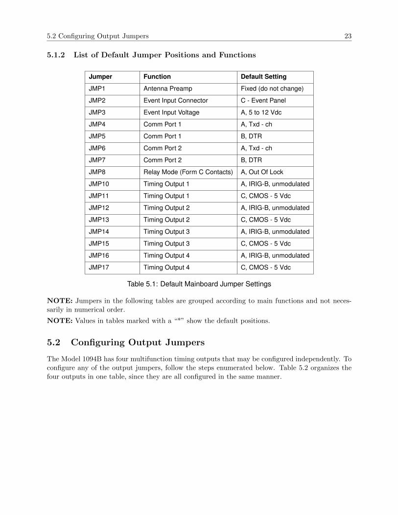
5.1.2 List of Default Jumper Positions and Functions
Jumper Function Default Setting
JMP1 Antenna Preamp Fixed (do not change)
JMP2 Event Input Connector C - Event Panel
JMP3 Event Input Voltage A, 5 to 12 Vdc
JMP4 Comm Port 1 A, Txd - ch
JMP5 Comm Port 1 B, DTR
JMP6 Comm Port 2 A, Txd - ch
JMP7 Comm Port 2 B, DTR
JMP8 Relay Mode (Form C Contacts) A, Out Of Lock
JMP10 Timing Output 1 A, IRIG-B, unmodulated
JMP11 Timing Output 1 C, CMOS - 5 Vdc
JMP12 Timing Output 2 A, IRIG-B, unmodulated
JMP13 Timing Output 2 C, CMOS - 5 Vdc
JMP14 Timing Output 3 A, IRIG-B, unmodulated
JMP15 Timing Output 3 C, CMOS - 5 Vdc
JMP16 Timing Output 4 A, IRIG-B, unmodulated
JMP17 Timing Output 4 C, CMOS - 5 Vdc
Table 5.1: Default Mainboard Jumper Settings
NOTE: Jumpers in the following tables are grouped according to main functions and not neces-sarily in numerical order.
NOTE: Values in tables marked with a “*” show the default positions.
5.2 Configuring Output Jumpers
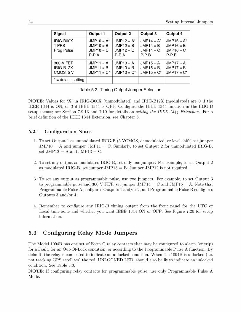
The Model 1094B has four multifunction timing outputs that may be configured independently. Toconfigure any of the output jumpers, follow the steps enumerated below. Table 5.2 organizes thefour outputs in one table, since they are all configured in the same manner.
24 Setting Internal Jumpers
Signal Output 1 Output 2 Output 3 Output 4
IRIG-B00X JMP10 = A* JMP12 = A* JMP14 = A* JMP16 = A*1 PPS JMP10 = B JMP12 = B JMP14 = B JMP16 = BProg Pulse JMP10 = C JMP12 = C JMP14 = C JMP16 = C
P-P A P-P A P-P B P-P B
300-V FET JMP11 = A JMP13 = A JMP15 = A JMP17 = AIRIG-B12X JMP11 = B JMP13 = B JMP15 = B JMP17 = BCMOS, 5 V JMP11 = C* JMP13 = C* JMP15 = C* JMP17 = C*
* = default setting
Table 5.2: Timing Output Jumper Selection
NOTE: Values for ‘X’ in IRIG-B00X (unmodulated) and IRIG-B12X (modulated) are 0 if theIEEE 1344 is ON, or 3 if IEEE 1344 is OFF. Configure the IEEE 1344 function in the IRIG-Bsetup menus; see Section 7.9.13 and 7.10 for details on setting the IEEE 1344 Extension. For abrief definition of the IEEE 1344 Extension, see Chapter 8.
5.2.1 Configuration Notes
1. To set Output 1 as unmodulated IRIG-B (5 VCMOS, demodulated, or level shift) set jumperJMP10 = A and jumper JMP11 = C. Similarly, to set Output 2 for unmodulated IRIG-B,set JMP12 = A and JMP13 = C.
2. To set any output as modulated IRIG-B, set only one jumper. For example, to set Output 2as modulated IRIG-B, set jumper JMP13 = B. Jumper JMP12 is not required.
3. To set any output as programmable pulse, use two jumpers. For example, to set Output 3to programmable pulse and 300 V FET, set jumper JMP14 = C and JMP15 = A. Note thatProgrammable Pulse A configures Outputs 1 and/or 2, and Programmable Pulse B configuresOutputs 3 and/or 4.
4. Remember to configure any IRIG-B timing output from the front panel for the UTC orLocal time zone and whether you want IEEE 1344 ON or OFF. See Figure 7.20 for setupinformation.
5.3 Configuring Relay Mode Jumpers
The Model 1094B has one set of Form C relay contacts that may be configured to alarm (or trip)for a Fault, for an Out-Of-Lock condition, or according to the Programmable Pulse A function. Bydefault, the relay is connected to indicate an unlocked condition. When the 1094B is unlocked (i.e.not tracking GPS satellites) the red, UNLOCKED LED, should also be lit to indicate an unlockedcondition. See Table 5.3.
NOTE: If configuring relay contacts for programmable pulse, use only Programmable Pulse AMode.

5.4 Configuring Communication Port Jumpers 25
Function JMP8, Jumper Position
Out of Lock A*
Fault B
Prog. Pulse A C
Table 5.3: Relay Jumper Positions
5.3.1 Relay Contact Specifications
Life expectancy (electrical) is 100,000 operations; resistive load test at 250 VAC, 8 A, room temper-ature with diode. Continuous monitoring must be performed to detect contact sticking and shortcircuit. Dielectric strength measured at 500 V for 1 minute with same polarity.
5.4 Configuring Communication Port Jumpers
The Model 1094B has two communication ports (COM1 and COM2) that can provide both RS-232C and RS-485 levels. Alternately, these ports may be configured to provide a programmablepulse output and IRIG-B at RS-485 levels. See Table 5.4 for details on jumper positions. SeeTable 10.1 for COM1 and COM2 pin definitions.
Driver Output Signal COM1 COM2
RS-232 Prog Pulse A JMP5=A JMP7=A
” DTR* JMP5=B JMP7=B
RS-485 TXD-Ch* JMP4=A JMP6=A
” Prog Pulse B JMP4=B JMP6=B
” IRIG-B JMP4=C JMP6=C
Table 5.4: Communication Port Jumper Selection
NOTE: COM1 can serve as an alternate port for Programmable Pulse A, and COM2 can serve asan alternate port for Programmable Pulse B.
1. For standard RS-232 communications on COM1 or COM2, move jumpers JMP5 or JMP7 toposition B.
2. To transmit a programmable pulse from COM ports at RS-232 levels, move jumper JMP5 orJMP7 to position A.
3. To transmit a programmable pulse from COM ports as RS-485, move jumper JMP4 or JMP6to position B.
4. To transmit IRIG-B data from either COM1 or COM2, move jumper JMP4 or JMP6 toposition C. To set up IRIG-B timing, use ”SET IRIG MAIN?” found in Section 7.10.

26 Setting Internal Jumpers
5.5 Configuring Event Input Jumpers
The Model 1094B has one Event Input function that has two modes: (1) Event Capture, and(2) 1-PPS Deviation measurement. Events may be recorded from two connection points: (1) thededicated event input connector, and (2) either COM1 or COM2. Using the dedicated Event Panelconnector, you can set the event input voltage level to one of three ranges: 5 to 12 Vdc, 24 to 48Vdc, or 120 to 240 Vdc. Alternately, you may capture RS-232 signals as an event at either COM1or COM2 (pin 2). Apply only RS-232 signal levels to COM1 or COM2. See Tables 5.5 and 5.6.
Input Connector Input Signal Jumper & Position
Event 5 - 12 Vdc JMP3 = A*
Event 24 - 48 Vdc JMP3 = B
Event 120 - 240 Vdc JMP3 = C
Table 5.5: Event Input Voltage Selection
Input Connector Jumper & Position
COM1 JMP2 = A
COM2 JMP2 = B
Event JMP2 = C*
Table 5.6: Event Input Connector Selection
5.5.1 Selecting the Event Input Channel and Voltage
1. Select the input channel as the designated BNC Event Input (default), COM1 or COM2 (pin2); choose jumper position A for COM1, B for COM2, or C for the BNC Event connector(default).
2. To select a voltage level, move jumper JMP3 to A for 5 to 12 Vdc (default), to B for 24 to48 Vdc, or to C for 120 to 240 Vdc.
5.5.2 Configuring the Event/1-PPS Function
Configure the Event Input feature by using the setup menus, through the front-panel keypad, orremotely through COM1 or COM2. To use the setup menus, see Section 7.12. To use either COM1or COM2, see Section 7.12 using the 1094 Utility, or Section 10.3.5, Event Mode Commands usinga terminal program.

Chapter 6
Clock Startup and Utility Software
6.1 Initial Startup Sequence
Before powering ON the Model 1094B, make sure that the chassis cover is installed and that inletpower is properly connected to the power inlet connector. The power switch is recessed to preventaccidental switching of power ON or OFF. When you slide the switch to ON, several things shouldhappen, as listed in the sequence below:
• The four annunciator LED’s initially should flash momentarily, then the OPERATE LEDand UNLOCKED LED should light steadily.
• The LCD should display several introductory messages - see below.
• The Out-of-Lock Relay (Fault) will be in the out-of-lock (or faulted) position.
• Eventually, the UNLOCKED LED should extinguish.
• The Out-of-Lock Relay should change to Locked condition after a few minutes (depends howlong the clock has been powered off).
• The LCD should indicate that the clock is Locked.
• The Stabilized LED should light steadily after a few minutes of locked operation.
6.1.1 Clock Time, Startup Mode
When the Model 1094B first starts, it will not indicate the correct time until it is locked to the GPS.Pressing the TIME key before the UNLOCKED LED is extinguished will produce the message:
TIME NOT AVAILABLE
For IRIG-B time, it will begin counting from zero, with the Julian Day also set to zero. Thismethod was chosen so that there would be no mistake in interpreting that the clock was in startupmode. For example, at startup the time could indicate as follows:
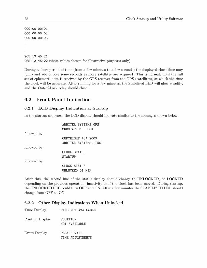
28 Clock Startup and Utility Software
000:00:00:01
000:00:00:02
000:00:00:03
.
.
.265:13:45:21
265:13:45:22 (these values chosen for illustrative purposes only)
During a short period of time (from a few minutes to a few seconds) the displayed clock time mayjump and add or lose some seconds as more satellites are acquired. This is normal, until the fullset of ephemeris data is received by the GPS receiver from the GPS (satellites), at which the timethe clock will be accurate. After running for a few minutes, the Stabilized LED will glow steadily,and the Out-of-Lock relay should close.
6.2 Front Panel Indication
6.2.1 LCD Display Indication at Startup
In the startup sequence, the LCD display should indicate similar to the messages shown below.
ARBITER SYSTEMS GPS
SUBSTATION CLOCK
followed by:COPYRIGHT (C) 2009
ARBITER SYSTEMS, INC.
followed by:CLOCK STATUS
STARTUP
followed by:CLOCK STATUS
UNLOCKED 01 MIN
After this, the second line of the status display should change to UNLOCKED, or LOCKEDdepending on the previous operation, inactivity or if the clock has been moved. During startup,the UNLOCKED LED could turn OFF and ON. After a few minutes the STABILIZED LED shouldchange from OFF to ON.
6.2.2 Other Display Indications When Unlocked
Time Display TIME NOT AVAILABLE
Position Display POSITION
NOT AVAILABLE
Event Display PLEASE WAIT!
TIME ADJUSTMENTS

6.2 Front Panel Indication 29
Status Display GPS RECEIVER STATUS
ACQUIRING SATS
6.2.3 Status Display Indications
There are three indications when successively pressing the STATUS key. These are as follows:
CLOCK STATUS
STARTUP*
*The second line will change between STARTUP, to UNLOCKED (with time), to LOCKED.as follows:
GPS RECEIVER STATUS
LOCKED
*Possible Receiver Status messages are:
BAD GEOMETRY
ACQUIRING SATS
POSITION HOLD
2D FIX
3D FIX
AUTO SURVEY
GPS tracking status message:
GPS TRACKING STATUS
TRACKING 12 SATS
*The number of tracked satellites can change from 0 to 12.EEPROM status message:
EEPROM STATUS
CORR. ERRORS 0
If the number of corrected (CORR.) errors begins to climb, contact the factory about replacing theEEPROM.
6.2.4 Event/Deviation Display
There are separate displays when pressing the EVENT/DEVIATION key, depending on the setting.Successive events appear when repeatedly pressing the EVENT/DEVIATION key, or if configuredfor DEVIATION, it will indicate the 1-PPS Deviation (updates once per second). If there are norecords, the display will indicate NO DATA.

30 Clock Startup and Utility Software
Event DisplayEVENT nnn
ddd:hh:ss.sssssss
Where:nnn = event number(001 to 300)ddd = day of year of the event(1 to 366)hh = hour of the event(00 to 23)mm = minute of the event(00 to 59)ss.sssssss = second and fractional seconds of the event
Deviation Display1 PPS: 0.00 µSSIGMA: 0.00 µS
6.2.5 IRIG-B Time Data
IRIG-B time is immediately sent out, when the 1094B is powered ON, from any Timing Outputport configured for IRIG-B as indicated above. Time will not be accurate until the Stabilized LEDglows steadily.
6.3 Clock Status Display Mode
When first applying power to the Model 1094B, the display will indicate several startup messages,then will revert to Clock Status mode condition called STARTUP. After a short time, while theGPS receiver begins collecting data from the GPS, it will indicate either UNLOCKED (XX Min)or LOCKED. One of several fault messages may be displayed if they exist.
• Out of Lock• Receiver Failure• Antenna Short (low antenna voltage)• Antenna Open (no current drawn by antenna system)
For additional information on internal faults, please see Table 2.2, Fault Indications and Messages,and Section 10.3.6, Status Mode Commands.
6.4 Time Display Modes
After establishing GPS satellite synchronization, display date and time information on the frontpanel by pressing the TIME key and scrolling through the four available displays. Press this keyto select the time display mode (UTC or Local) time data (Date/Time or Day of Year).
6.4.1 Date and Time Display, Universal Time Coordinated (UTC)
This mode displays UTC, in the Date and Time format, as maintained by the United States NavalObservatory (USNO), as described below:
UTC DATE/TIME www
dd mmm yyyy hh:mm:ss

6.4 Time Display Modes 31
Where:www = day of the week (Mon - Sun)dd = day of the monthmmm = month (Jan - Dec)yyyy = the yearhh = the hour (00 - 23)mm = the minute (00 - 59)ss = the second (00 - 59)
This mode displays UTC, Time of Year mode, without the application of daylight saving correctionand local offset.
6.4.2 Time of Year Display, Universal Time Coordinated, (UTC)
This mode also displays UTC, in Time of Year format, which differs from the previous format asfollows:
UTC DATE/TIME www
yyyy ddd:hh:mm:ss
Where:ddd = day of the year (001 - 366)
This mode displays UTC, Time of Year mode, without the application of daylight saving correctionand local offset. NOTE: Daylight saving and local-offset have no effect on this display.
6.4.3 Date and Time Display, Local Time
This mode displays the date and time after the daylight-saving correction and local offset havebeen applied, but in the same format as that of the Date and Time, UTC:
LOCAL DATE/TIME www
dd mmm yyyy hh:mm:ss
6.4.4 Time of Year Display, Local Time
This mode displays the time of year after the daylight-saving correction and local offset have beenapplied, but in the same format as that of the Time of Year, UTC:
LOCAL DATE/TIME www
yyyy ddd:hh:mm:ss
NOTE: Unless the daylight saving and local offset parameters have been set properly, displays inSections 6.4.3 and 6.4.4 may not reflect the correct local time.
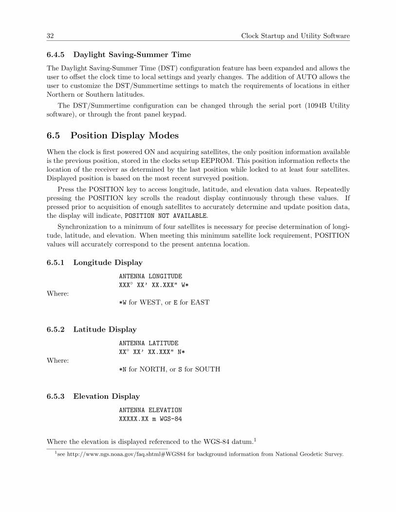
32 Clock Startup and Utility Software
6.4.5 Daylight Saving-Summer Time
The Daylight Saving-Summer Time (DST) configuration feature has been expanded and allows theuser to offset the clock time to local settings and yearly changes. The addition of AUTO allows theuser to customize the DST/Summertime settings to match the requirements of locations in eitherNorthern or Southern latitudes.
The DST/Summertime configuration can be changed through the serial port (1094B Utilitysoftware), or through the front panel keypad.
6.5 Position Display Modes
When the clock is first powered ON and acquiring satellites, the only position information availableis the previous position, stored in the clocks setup EEPROM. This position information reflects thelocation of the receiver as determined by the last position while locked to at least four satellites.Displayed position is based on the most recent surveyed position.
Press the POSITION key to access longitude, latitude, and elevation data values. Repeatedlypressing the POSITION key scrolls the readout display continuously through these values. Ifpressed prior to acquisition of enough satellites to accurately determine and update position data,the display will indicate, POSITION NOT AVAILABLE.
Synchronization to a minimum of four satellites is necessary for precise determination of longi-tude, latitude, and elevation. When meeting this minimum satellite lock requirement, POSITIONvalues will accurately correspond to the present antenna location.
6.5.1 Longitude Display
ANTENNA LONGITUDE
XXX XX’ XX.XXX" W*
Where:*W for WEST, or E for EAST
6.5.2 Latitude Display
ANTENNA LATITUDE
XX XX’ XX.XXX" N*
Where:*N for NORTH, or S for SOUTH
6.5.3 Elevation Display
ANTENNA ELEVATION
XXXXX.XX m WGS-84
Where the elevation is displayed referenced to the WGS-84 datum.1
1see http://www.ngs.noaa.gov/faq.shtml#WGS84 for background information from National Geodetic Survey.

6.6 Application Software – 1094B Utility 33
6.6 Application Software – 1094B Utility
1094 Utility application software was developed to configure the Model 1094B and to verify theconfiguration. From the verification, you can create a unique configuration for other clocks withthe same performance characteristics.
6.6.1 Configuring with 1094B Utility Software
The following sections illustrate how to use the 1094B Utility software to configure the 1094B.
It is not necessary to have the 1094B locked to the GPS while configuring it. Time and positiondata, however, will not be accurate.
The most efficient method for configuring is through the use of the 1094B Utility software thataccompanies the clock. It is also possible to program the Model 1094B by sending basic commandsthrough a terminal, or terminal emulation program. These commands are listed in Chapter 10,Serial Communication and Command Set.
1094B Utility software allows you to read, write and verify operation on the Model 1094B.While it is idle, it releases the serial port on your pc for use. For pc’s without serial ports, you willneed to use a USB to serial converter.
To obtain the 1094 Utility appliction software, go to the Arbiter website and select SoftwareDownloads under Site Navigation2. Scroll down to Timing Software and select Model 1094B Soft-ware. Download the 1094 Utility to your computer. Double click the icon and in a few moments theprogram should start as illustrated in Figure 6.1. The 1094 Utility does not need to be installed.
Figure 6.1: 1094B Utility Software, Opening Window
2Download from http://www.arbiter.com/catalog/clock/1094/1094ware.php

34 Clock Startup and Utility Software
6.6.2 Establishing a Serial Connection
NOTE: To connect with the Model 1094B you must use a null-modem cable between the Model1094B and computer; signals between Tx and Rx are crossed. Pin connections and functions areas follows:
PC – 1094B3, Tx – 2, RxD2, Rx – 3, TxD5, Gnd – 5, GND
For computers without a serial port, you will most likely need to use a USB to serial converter.These devices normally associate a COM port number (on your computer) with the USB device.For the Windows XP operating system, you may look this up as described on the next page.
From the 1094 Utility, select Settings > Serial Port > COM #, choosing the correct COM portassociated with your computer – see Figure 6.2. If your computer has its own serial port, choosethat one. If you are using a USB-to-Serial converter, choose the one that is associated with yourconverter.
Make sure to go back and select Settings > Baud Rate, choosing the same baud rate as on theModel 1094B. To check the baud rate on your Model 1094B, press the SETUP key on the clock; thefirst menu should state, “SET SERIAL COM 1?”; press SETUP again and the second menu shouldstate “SET SERIAL COM 2?”. Press ENTER to verify the port parameters for either COM1 orCOM2.
Figure 6.2: Connecting with the 1094B
See the next page for information on identifying the COM port being used by your USB-to-Serialadapter on your pc. The pc operating system in Figure 6.4 is Windows XP.
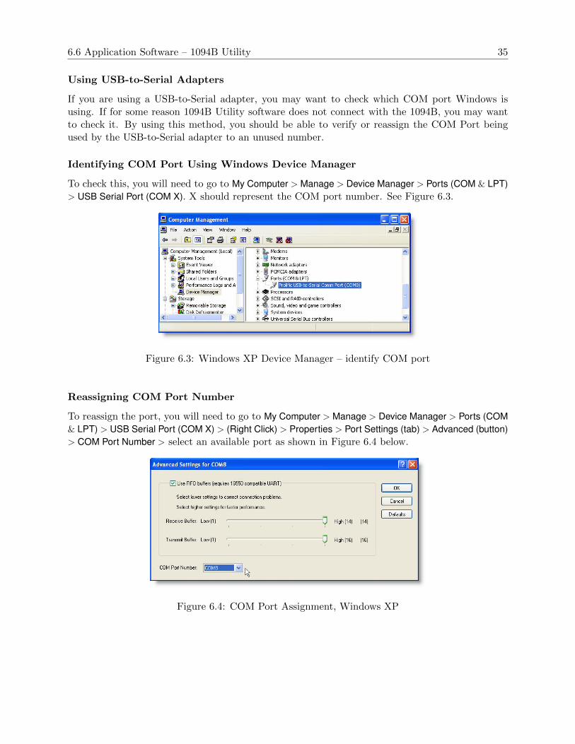
6.6 Application Software – 1094B Utility 35
Using USB-to-Serial Adapters
If you are using a USB-to-Serial adapter, you may want to check which COM port Windows isusing. If for some reason 1094B Utility software does not connect with the 1094B, you may wantto check it. By using this method, you should be able to verify or reassign the COM Port beingused by the USB-to-Serial adapter to an unused number.
Identifying COM Port Using Windows Device Manager
To check this, you will need to go to My Computer > Manage > Device Manager > Ports (COM & LPT)> USB Serial Port (COM X). X should represent the COM port number. See Figure 6.3.
Figure 6.3: Windows XP Device Manager – identify COM port
Reassigning COM Port Number
To reassign the port, you will need to go to My Computer > Manage > Device Manager > Ports (COM& LPT) > USB Serial Port (COM X) > (Right Click) > Properties > Port Settings (tab) > Advanced (button)> COM Port Number > select an available port as shown in Figure 6.4 below.
Figure 6.4: COM Port Assignment, Windows XP

36 Clock Startup and Utility Software
6.6.3 Reading Clock Configuration
When first starting 1094 Utility there will be two functions open: Open and Read. Open selects afile to upload to a connected clock. Open a file by selecting File > Open or by clicking the Openicon (blue folder). Read allows you to poll the connected Model 1094B and download all of theconfigured information. You can find Read by either by selecting Unit > Read, or by clicking theRead icon. When selecting the Read function by either method, 1094 Utility will immediately tryto read the configured settings in the connected clock. If it is successful, it will show a progress barfor a few seconds and then populate all of the values in the 1094 Utility windows. See Figure 6.5.
Figure 6.5: Reading the 1094B Configuration
If for some reason you get a message that the 1094B Utility software could not read the clock,make sure to check Settings at the top of the 1094B Utility window to verify (1) you are trying toconnect using the correct COM port on your pc, (2) that you are using the correct baud rate, orother settings, and (3) that you have the correct cable(s) connected between the Model 1094B andthe pc. Note that it must be a null-modem cable – see table in Section 6.6.2.
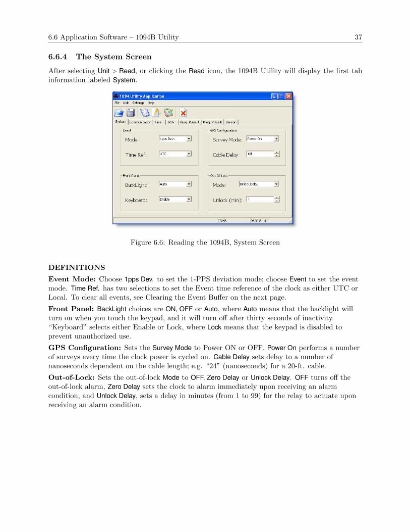
6.6 Application Software – 1094B Utility 37
6.6.4 The System Screen
After selecting Unit > Read, or clicking the Read icon, the 1094B Utility will display the first tabinformation labeled System.
Figure 6.6: Reading the 1094B, System Screen
DEFINITIONS
Event Mode: Choose 1pps Dev. to set the 1-PPS deviation mode; choose Event to set the eventmode. Time Ref. has two selections to set the Event time reference of the clock as either UTC orLocal. To clear all events, see Clearing the Event Buffer on the next page.
Front Panel: BackLight choices are ON, OFF or Auto, where Auto means that the backlight willturn on when you touch the keypad, and it will turn off after thirty seconds of inactivity.“Keyboard” selects either Enable or Lock, where Lock means that the keypad is disabled toprevent unauthorized use.
GPS Configuration: Sets the Survey Mode to Power ON or OFF. Power On performs a numberof surveys every time the clock power is cycled on. Cable Delay sets delay to a number ofnanoseconds dependent on the cable length; e.g. “24” (nanoseconds) for a 20-ft. cable.
Out-of-Lock: Sets the out-of-lock Mode to OFF, Zero Delay or Unlock Delay. OFF turns off theout-of-lock alarm, Zero Delay sets the clock to alarm immediately upon receiving an alarmcondition, and Unlock Delay, sets a delay in minutes (from 1 to 99) for the relay to actuate uponreceiving an alarm condition.

38 Clock Startup and Utility Software
Clearing the Event Buffer
To clear all events stored in the event buffer, select Unit > Clear Events, or click the X icon on theright (above the Prog Pulse A tab) – see Figure 6.7.
While broadcasting event records, the buffer will continually be overwritten with new data.Therefore, you would not need to use the Clear feature while broadcasting event data.
Figure 6.7: Clearing Events in the 1094B

6.6 Application Software – 1094B Utility 39
6.6.5 The Communication Screen
Select the Communication tab to view and configure any communication parameters, includingbroadcast modes – see Figure 6.8. The 1094B Utility software reads from and configures eitherCOM1 or COM2.
Select from a number of pre-configured broadcast messages, or two custom broadcast messages,which may be created through the scripting as described in Section 10.3.2.
Figure 6.8: Communication Settings Screen
DEFINITIONS
COM Port Configuration: Allows for configuring COM Port parameters using this softwareutility; Sets baud rate, word length, parity and stop bits. 1094B ports do not use flow control.
Broadcast Configuration: Set Message Type according to the list of configured broadcastmessages. Custom messages may also be configured. Set broadcast rate and broadcast timereference to either UTC or Local. To review information on customizing a broadcast string, seeSection 10.3.1.
To review the actual custom string codes as they exists in the Model 1094B, use the mCBcommand in a terminal window, where m = 0 for Custom 1 and m = 1 for Custom 2.
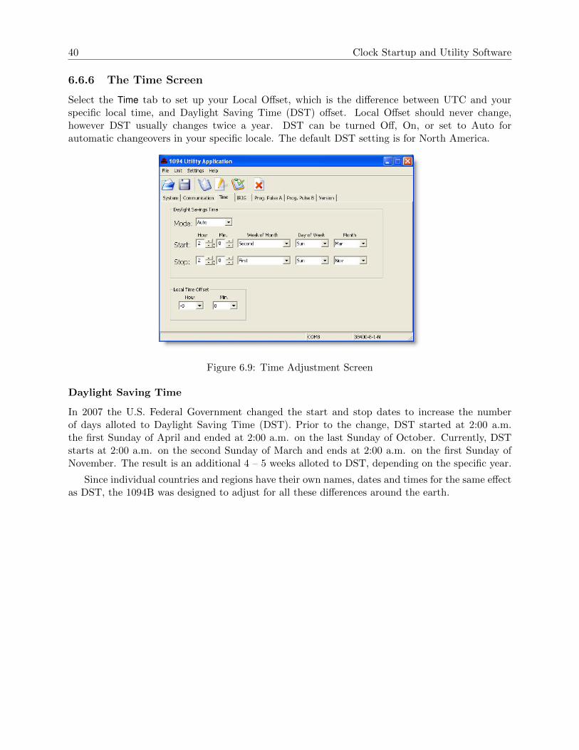
40 Clock Startup and Utility Software
6.6.6 The Time Screen
Select the Time tab to set up your Local Offset, which is the difference between UTC and yourspecific local time, and Daylight Saving Time (DST) offset. Local Offset should never change,however DST usually changes twice a year. DST can be turned Off, On, or set to Auto forautomatic changeovers in your specific locale. The default DST setting is for North America.
Figure 6.9: Time Adjustment Screen
Daylight Saving Time
In 2007 the U.S. Federal Government changed the start and stop dates to increase the numberof days alloted to Daylight Saving Time (DST). Prior to the change, DST started at 2:00 a.m.the first Sunday of April and ended at 2:00 a.m. on the last Sunday of October. Currently, DSTstarts at 2:00 a.m. on the second Sunday of March and ends at 2:00 a.m. on the first Sunday ofNovember. The result is an additional 4 – 5 weeks alloted to DST, depending on the specific year.
Since individual countries and regions have their own names, dates and times for the same effectas DST, the 1094B was designed to adjust for all these differences around the earth.

6.6 Application Software – 1094B Utility 41
6.6.7 The IRIG-B Screen
Select the IRIG tab to set up how the 1094B sends out IRIG-B to your connected relays andIED’s. Channel A refers to the two specific connectors labeled IRIG-B (unmodulated) and IRIG-BMod (modulated). One mode of Prog. Pulse B allows you to configure IRIG-B differently thanfor Channel A (see Section 6.6.9), providing a separate and independent instance of unmodulatedIRIG-B.
Figure 6.10: IRIG-B Adjustment Screen
IRIG-B Connection & Timing Information
For additional information on time codes, IRIG-B and connecting the Model 1094B to other equip-ment, please go to Chapter 8. Additionally, several application notes and white papers addressconnection issues in more depth, and are listed below. These may be obtained from the Arbiterwebsite at http://www.arbiter.com/ftp/datasheets.
appnote101.pdfirig accuracy and connection requirements.pdfirig b spec brief.pdf
If the link does not work correctly, you should be able to find them athttp://www.arbiter.com/ftp.
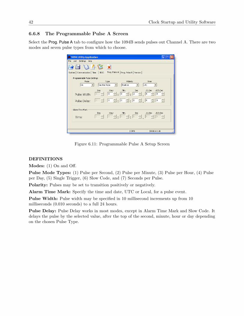
42 Clock Startup and Utility Software
6.6.8 The Programmable Pulse A Screen
Select the Prog. Pulse A tab to configure how the 1094B sends pulses out Channel A. There are twomodes and seven pulse types from which to choose.
Figure 6.11: Programmable Pulse A Setup Screen
DEFINITIONS
Modes: (1) On and Off.
Pulse Mode Types: (1) Pulse per Second, (2) Pulse per Minute, (3) Pulse per Hour, (4) Pulseper Day, (5) Single Trigger, (6) Slow Code, and (7) Seconds per Pulse.
Polarity: Pulses may be set to transition positively or negatively.
Alarm Time Mark: Specify the time and date, UTC or Local, for a pulse event.
Pulse Width: Pulse width may be specified in 10 millisecond increments up from 10milliseconds (0.010 seconds) to a full 24 hours.
Pulse Delay: Pulse Delay works in most modes, except in Alarm Time Mark and Slow Code. Itdelays the pulse by the selected value, after the top of the second, minute, hour or day dependingon the chosen Pulse Type.

6.6 Application Software – 1094B Utility 43
6.6.9 The Programmable Pulse B Screen
Select the Prog. Pulse B tab to configure how the 1094B sends pulses out Channel B. There arefour modes and seven pulse types from which to choose. Prog. Pulse B is identical to Prog. Pulse Aexcept that it includes two additional modes: (1) Frequency, and (2) IRIG-B. Channel B, IRIG-Bis independent from Channel A.
Figure 6.12: Programmable Pulse B Setup Screen
Modes: (1) Off, (2) Pulse, (3) Frequency, and (4) IRIG-B.
Pulse Mode Types: (1) Pulse per Second, (2) Pulse per Minute, (3) Pulse per Hour, (4) Pulseper Day, (5) Single Trigger, (6) Slow Code, and (7) Seconds per Pulse.Frequency: Set frequency, from 1 to 1000, in pulses per second; no other settings are available.Pulses have 50 percent duty cycle.
IRIG-B: Select IRIG-B as Mode and go to IRIG-B tab, Channel B, to set up IRIG-B preferences.
Polarity, Alarm Time Mark, Pulse Width, and Pulse Delay: See definitions on Pro-grammable Pulse A in Section 6.6.8.

44 Clock Startup and Utility Software
6.6.10 The Version Screen
Choose the Version tab to view the firmware version of the Model 1094B, which is defined by therelease date.
Figure 6.13: 1094B Version Display Screen
6.6.11 Setting to Factory Defaults
At some time it may be advisable to reset the Model 1094B to its original firmware configurationwhen it left the factory. To return the Model 1094B firmware configuration to factory defaults,follow the instructions enumerated below. After resetting, you can use the 1094 Utility to save thedefault configuration to file.
1. Power ON the Model 1094B.
2. Press the SETUP key when you see the first message displayed on the LCD, and displaymessage should change to:
SET FACTORY DEFAULTS?PRESS ENTER
3. Press the Enter key and the message should change to:
ARE YOU SURE?YES = UP NO = DOWN
4. Press the UP key to complete the reset to defaults. The display should display the followingmessage.
DEFAULTS COMPLETE
5. The factory default settings should now be restored.

6.7 Uploading New Firmware using the 109x Loader . . . 45
6.6.12 Saving a Configuration File
After going to the trouble of configuring all of the settings in a new Model 1094B, the 1094B Utilityallows you to save the configuration to a file.
To save a configuration file of the current clock setup, select File > Save, or click the Save iconin the 1094B Utility. When you do so, a Save Configuration window will appear for you to enter afile name and select a file location for the configuration file. The file will attach a “.1094” extensionto the name.
6.6.13 Opening a New Configuration
You may Open a new configuration file for your Model 1094B either before or after reading fromthe connected clock. If you did not Read the 1094B first, make sure to check the Settings, especiallythe COM Port number.
1. Select File>Open, or click the Open folder icon, and choose the configuration file for uploadingto the 1094B. The 1094B Utility will read the file and populate all of the configuration itemsin each tabbed display.
2. Select Unit > Write, or click the Write icon, and the progress window should indicate that thefile is being written to the unit.
3. At the end, you can verify that the new configuration matches the file by selecting Unit >Verify or by clicking the Verify icon.
During the verification process, the program will compare all of the configurations in theModel 1094B with those of the file. A progress bar will indicate the comparison. At the end,a window will appear and identify any items that did not match.
4. With no verification problems, the Model 1094B should now be updated.
Programming Multiple Units5. If you have multiple units to program, you should be able to connect the cable to the next
unit and select Unit > Write, or click the Write icon. Assuming the other clocks have the sameCOM port parameters, programming should be very quick.
6.7 Uploading New Firmware using the 109x Loader . . .
NOTE: Warning! Do not halt the upload process once it has started or the Model 1094B maynot be recoverable. This includes removing power from the 1094B, disconnecting the serial cable orturning off the computer during the uploading process. To recover you will be required to return theclock to Arbiter Systems.
To upload new firmware to the Model 1094B, use 109x loader v####.exe; this loader and thenew firmware may be downloaded from the Arbiter website. From the left side of the home page,in the selection window, select 1094B Software/Firmware. Be sure to read the release notes, whichprovide dates and fixes in the software or firmware.
6.7.1 Using the Uploader
1. Connect a null-modem cable between the computer and the serial port on the Model 1094B.2. Start the loader program and click the folder icon, or select File > Open.

46 Clock Startup and Utility Software
3. Locate the new 1094B firmware zip file (the loader automatically extracts the file) and clickthe Open button. The loader window should indicate some basic information about the file,including the firmware version by date. See Figure 6.14.
Figure 6.14: 1094B Loader with Opened Firmware File
4. Select Settings > Serial Port to choose the correct serial port.5. Select Settings > Baud rate to choose the same baud rate as that of the 1094B.6. Click the blue UP arrow to load the firmware into the Model 1094B. Figure 6.15 indicates
what you should see after a successful uploading session. During the upload process, theprogram will show a progress bar that indicates erasing flash and then uploading the newfirmware. The process time will vary due to the set baud rate and file size.
Figure 6.15: Successful Upload of New Firmware
7. After successfully uploading new firmware, close the 109x loader program.8. If the firmware did not successfully upload, first check the COM settings (i.e. COM port
number and baud rate), and try again. Also, verify that the cable/connection is good.

Chapter 7
The Setup Menus
This section should guide you in configuring the Model 1094B operation using the SETUP Menusfrom the front panel. These menus allow you to configure the 1094B according to your preferences.Logically, using the setup menus should follow after setting any of the main board jumpers (seeChapter 5).
Two of the most common setup menus for any application are (1) configuring the Local Offsetand Daylight Saving values, and (2) setting up the IRIG-B outputs for the correct time zone.For the 1094B to operate with the correct time in your location, you will need to configure theLocal Offset (from UTC) and Daylight Savings, or Summer Time, changeover settings. There area number of other settings that may be important to your application, however local time offsetsare normally fundamental requirements. For a complete list of setup menus, see Table 7.1.
There are two methods of configuring the 1094B: (1) Using the lower row of keys on the frontpanel, and (2) remotely, by using either COM1 or COM2. For information on configuring the 1094Bremotely through either COM1 or COM2, please refer to Chapter 10, Serial Communication andCommand Set.
No. Setup Menus Setup Items
1 Serial COM1 Serial 1 Port Parameters and Broadcast2 Serial COM2 Serial 2 Port Parameters and Broadcast3 Local Time Set Local Offset and DST/Summer Time4 Out Of Lock Set Time Interval Before Alarm5 Backlight Set to ON, OFF or AUTO6 Cable Delay Set Delay in Nanoseconds7 Programmable Pulse A Set Mode and Pulse Width8 Programmable Pulse B Set Mode and Pulse Width9 IRIG-B Main Set IRIG-B Time Zone and IEEE-134410 Set Auto Survey Set Type of Survey and turn off11 Event/Deviation Set for either Events or 1 PPS Deviation
Table 7.1: Front-Panel Setup Menus
7.1 Setup Menus
Table 7.1, lists the various menus used to configure the operation of the Model 1094B. Otherdefinitions follow the list that discuss how to begin configuring, the function of each key, and how

48 The Setup Menus
to escape the configuration process if necessary. After this introductory material, each menu iscovered in detail.
7.1.1 To Begin Configuring
Press the SETUP key to enter the clock configuration menus, starting with communication portparameters (Set Serial COM1?).
SETUP: Press the Setup key repeatedly to scroll through the main menus. Also, after pressingSETUP once, you can press the UP or DOWN keys to scroll the menus. In numeric data entrymode, pressing SETUP moves the cursor to the left.
ENTER: Press the Enter key to confirm changes made within SETUP menus. Generally, pressingENTER also advances the next parameter, or returns to the previous menu level. In numeric dataentry mode, pressing ENTER moves the cursor to the right.
UP: Press the UP key, within the SETUP menus, to adjust numerical values upward, or to scrollupward through the available menu choices. The UP key also assists in navigating through mainSetup Menus in normal order.
DOWN: Press the DOWN key, within the SETUP menu, to adjust numerical values downward, orto scroll downward through available menu choices. Also assists in navigating through main Setupmenus in reverse order.
7.1.2 Numeric Data Entry Mode
Numeric data entry mode is activated anytime you enter a menu that requires a change in numericalvalue. When in this mode, the function of the SETUP and ENTER keys change to give left andright cursor control.
7.1.3 Default Firmware Settings
When shipped from the factory, and unless specified otherwise, the Model 1094B will be configuredwith a default set of values and features. This set of values and features are configured primarilythrough the front panel, lower row of keys, and alternately through either communication port.These default settings are listed in Table 7.2 below. For menu order, read table from left to right,and down.
7.1.4 To Exit Setup Menus
To exit any configuration menu without saving, press any key of the upper row of keys beforepressing ENTER to change a value. To return to the configuration menus, press SETUP again. Ifyou make a configuration error, you can scroll through the menus again and press ENTER whenyou find the menu you want to change.

7.2 Set Serial COM1 49
Menu Item Function Menu Item Function
COM1 DTR, 9600, 8, N, 1 COM2 DTR, 9600, 8, N, 1
Local Offset none Daylight Saving OFF
Out-of-Lock 01 min. Backlight Auto
Cable Delay 60 ns Prog Pulse A Pulse Mode
Prog Pulse B Pulse Mode IRIG-B Main 1344 OFF, UTC
Auto Survey Power On Survey Event/Deviation Deviation
Table 7.2: Default Firmware Settings
7.2 Set Serial COM1
Press SETUP key to configure Serial COM1. To enter the Set Serial COM1 menu, press the SETUPkey and then the ENTER key. After this you will be able to choose between configuring the serialport parameters (PORT CONFIG) or selecting one of the broadcast options (BROADCAST). Ifyou select BROADCAST, by pressing the DOWN key, you will also be able to select the preferredtime zone in the broadcasted string (either UTC or LOCAL). See Figure 7.1.
Figure 7.1: COM1 Setup
7.3 Set Serial COM2
Setup Serial COM2 in the same manner as for Set Serial COM1. From any view menu, press theSETUP key twice and then the ENTER key. Follow the on screen instructions as described abovefor Set Serial COM1.
Figure 7.2: COM2 Setup

50 The Setup Menus
7.3.1 Set Broadcast Mode from Serial COM1
From the menu shown in Figure 7.1, press the DOWN key to select the Broadcast option and setup the 1094B to broadcast one of the available strings. Press the UP or DOWN keys to navigatethrough the seventeen choices for the broadcast strings, starting with INTERROGATE MODE(as seen in Figure 7.3). Interrogate Mode means that the 1094B is not broadcasting, but waitingfor a command. When you have selected the desired broadcast string, press ENTER to apply thebroadcast. For broadcast strings other than INTERROGATE MODE, two menus should follow:(1) select the time zone (UTC or Local), and (2) select the broadcast rate (1 to 9999 secondsbetween successive broadcasts, depending on type of broadcast).
Figure 7.3: Broadcast Mode Setup
For a full list and discussion of these strings, please see Section 10.3.2, Broadcast Mode Com-mands.

7.4 Set Local Offset 51
7.3.2 Configure Serial COM1 Port Parameters
To set COM parameters, press the UP key as shown in Figure 7.1. Work through each menu toselect your desired settings – see Figure 7.4.
Figure 7.4: COM1 and COM2 Parameter Setup
Configure COM1 and COM2 in the same manner as shown in Figure 7.4. The “SET SERIALCOM2?” menu immediately follows the “SET SERIAL COM1?” menu. Another method of directlyentering the SET SERIAL COM2? menu is to press the SETUP key twice.
7.4 Set Local Offset
The Local Offset equals the difference in time (in 15-minute increments) from UTC (or GMT) toyour time zone. Locations west of the Prime Meridian have negative offsets and locations east ofthe Prime Meridian have positive offsets. For example, Karachi is +5 hours and New York is -5hours offset from UTC – see Figure 7.5.
Figure 7.5: Local Time Setup

52 The Setup Menus
7.5 Set DST/Summer Time
Daylight Saving and Summer Time are hereafter referred to as DST. These settings follow imme-diately after setting the Local Offset, and are actually part of the Local Offset main menu. DSTsettings are normally used to advance and retard the time once each year. The menus in thissection allow you to customize the clock time for your region in 15 minute increments over a plusor minus 12-hour interval.
Continuing from the Local Offset menu, follow the menus below to complete the DST setup.After setting the Local Offset, there are two basic values that are necessary to complete thisconfiguration:
• DST Start Date and Time
• DST Stop Date and Time
The menu in Figure 7.6 illustrates how to set up the Start Date and Time. The Stop Date andTime menus are nearly identical except that the menus say “STOP” instead of “START,” the stopMonth is “November”, and the stop week is “First.” Before setting up your DST feature, make surethat you understand when DST starts and stops in your region. In each menu, the list of selectionsare shown with each category.
Figure 7.6: Daylight Saving and Summer Time Setup

7.6 Set Out of Lock 53
7.6 Set Out of Lock
Set the Out-of-Lock time to control how the clock generates an alarm when it loses synchronizationwith the Global Positioning System. If set to OFF, the Out-of-Lock function will not give an alarm.If set to Zero Delay, then it will alarm immediately with an unlocked indication. If set to a value inminutes, then the 1094B will signal an alarm the configured number of minutes after an out-of-lockcondition occurs. This is different than when the Model 1094B first operates at startup. Duringstartup, the 1094B will immediately trigger an out-of-lock alarm since the clock is not locked tothe GPS and the time is not accurate. See Figure 7.7.
Figure 7.7: Out-of-Lock Time Setup
7.7 Set Backlight
The backlight function in the Model 1094B can be set to operate in three modes: Always ON,Always OFF and Automatic Shutoff (AUTO). AUTO is the most recommended setting, whichcauses the backlight to turn off automatically after period of 30 seconds of inactivity. See Figure 7.8.
NOTICE: The backlight has been specified with a 100,000 hour (11.4 year) life. To conserve backlightoperation, configure the backlight for AUTO mode for normal operation.
Figure 7.8: Backlight Setup

54 The Setup Menus
7.8 Set Cable Delay
GPS time is referenced to the time it is received by the antenna. Without setting the cable delay,the time would be late by the time it would take to travel the distance from the antenna to theGPS receiver. To accurately set the cable delay, you need to know the length and velocity factor ofthe antenna cable. For the cable supplied with the Model 1094B, calculate the delay by multiplyingthe the length of the cable (in feet) by 1.19 nanoseconds per foot. The result of this calculationwill be in nanoseconds, and you can enter in the whole part of this number into the 1094B. SeeFigure 7.9.
Calculating Cable Delay
Use Formula 7.1 below for calculating cable delay for Arbiter-supplied RG-6 antenna cables.
(7.1) T = λ1
CKv+ 1ns
Where:
T = Cable delay, in nanoseconds;λ = Cable length, in meters;C = Speed of light (3× 10⁸ meters per second);Kv = Nominal velocity of propagation (0.85).
One nanosecond is added to the calculated value to account for the length and velocity factorof the short connecting cable inside of the clock.
EXAMPLE: A 50-foot antenna cable would contribute the following delay; 50 ft. x 1.19 ns/ft =59.5 (round up and enter 60).
Figure 7.9: Cable Delay Setup
Numeric Data Entry Mode Numeric data entry mode is activated anytime you enter a menuthat requires a change in numerical value. Press SETUP to move the cursor to the left; pressENTER to move the cursor to the right. Press the UP and DOWN keys to adjust values.

7.9 Set Programmable Pulse A and B 55
7.9 Set Programmable Pulse A and B
There are two independent programmable pulse outputs available in the Model 1094B: Pro-grammable Pulse A and Programmable Pulse B. Pulses may be connected at the following ports:
• Prog Pulse A, Available on Timing Outputs 1 and 2, and on COM1.
• Prog Pulse B, Available on Timing Outputs 3 and 4, and on COM2.
Each of these outputs can be set in one of several modes, including:
7.9.1 Programmable Pulse A
• Pulse Per Second, pulses occur after a fractional number of seconds have elapsed eachsecond.
• Pulse Per Minute, pulses occur at the designated time each minute
• Pulse Per Hour, pulses occur at the designated time, each hour
• Pulse Per Day, pulses occur at the designated time each day
• Single Trigger, pulses occur at the designated time each year
• Slow Code UTC, Slow Code is a programmable pulse with a voltage that is held high andgoes low for 6 seconds on the day, 4 seconds on the hour and 2 seconds on the minute.
• Seconds-Per-Pulse, pulses occur after the chosen number seconds have elapsed, from 0 to60,000, programmed in 10 millisecond increments.
7.9.2 Programmable Pulse B
Programmable Pulse B has all of the features of Programmable Pulse A, but also includes:
• Frequency Mode, allows the 1094B to produce a square wave on the chosen port, from 1to 1000 pulses per second, 50 percent duty cycle.
• Auxiliary IRIG-B Mode, allows the 1094B to produce an alternate IRIG-B timing signal,different than what is set in Main IRIG-B. It allows for a different time zone and capabilityof switching the IEEE 1344 mode ON or OFF.
7.9.3 Programmable Pulse Signal Levels
Due to the different output ports available, the programmable pulse feature is able to producepulses at the following signal levels:
• 5 V, CMOS, available at all timing outputs.
• 300 V FET, available at all timing outputs, for open drain signals.
• RS-232 Levels, available with Programmable Pulse A on COM1, and B on COM2.
• RS-485 Levels, available with Programmable Pulse A on COM1, and B on COM2.
• Relay Contacts, available with Programmable Pulse A only. See Section 5.3.

56 The Setup Menus
7.9.4 Programmable Pulse A or B Preliminary Setup
Except for two additional modes with Programmable Pulse B (i.e. Frequency Mode and Aux IRIGMode), setting up the preliminary information for Programmable Pulse A and B is the same andwill be covered here. You will need to choose the Pulse Mode, Pulse Polarity (positive or negative),Pulse Width and Pulse Time Zone. Pulse Width is adjustable in 10 millisecond increments from0.01 to 600 seconds. See Figure 7.10.
Figure 7.10: Programmable Pulse Setup, Preliminary Information
7.9.5 Setting the Pulse-Per-Second Mode
Use the Pulse-per-Second mode to produce a pulse every second at the set number of fractionalseconds after the top of the second. Adjust the time delay after the on-time second mark at whichthe pulse will occur. Delay values range from 0.01 to 0.99 seconds. See Figure 7.11.
Figure 7.11: Programmable Pulse Setup, Pulse Per Second
Note: Pulse width can be from 0.01 to 0.99 seconds, otherwise it is set to 0.01.

7.9 Set Programmable Pulse A and B 57
7.9.6 Setting the Pulse-Per-Minute Mode
Use the Pulse-per-Minute mode to produce a pulse every minute, at the set number of seconds (andfractional seconds) after the top of the minute. See Figure 7.12.
Figure 7.12: Programmable Pulse Setup, Pulse Per Minute
Note: Pulse width can be set in 10 millisecond increments from 0.01 to 59.99 seconds, otherwiseit is set to 0.01.
7.9.7 Setting the Pulse-Per-Hour Mode
Use the Pulse-Per-Hour mode to produce a pulse every hour at the set number of seconds (andfractional seconds) after the top of the hour. See Figure 7.13.
Figure 7.13: Programmable Pulse Setup, Pulse Per Hour
Note: Pulse width can be set in 10 millisecond increments from 0.01 to 600 seconds.

58 The Setup Menus
7.9.8 Setting the Pulse-Per-Day Mode
Use the Pulse-Per-Day mode to produce one pulse each day at the set number of seconds (andfractional seconds) after midnight. See Figure 7.14.
Figure 7.14: Programmable Pulse Setup, Pulse-Per-Day Mode
Note: Pulse width can be set in 10 millisecond increments from 0.01 to 600 seconds.
7.9.9 Setting the Single-Trigger Mode
Use the Single Trigger mode to trigger a pulse once per year at a specific day of the year and timeof day. Setup menus include entries for Julian Day, Hour, Minute, Second and Fractional Seconds.To configure Single-Trigger mode settings, follow the procedure illustrated in Figure 7.15.
Figure 7.15: Programmable Pulse Setup, Single-Trigger Mode

7.9 Set Programmable Pulse A and B 59
7.9.10 Setting the Slow-Code Mode
Use the Slow-Code mode to trigger a pulse normally defined as follows: the output voltage isnormally held high and it will go low for 2 seconds on the minute, 4 seconds on the hour and 6seconds on the day. Set the time mode for either UTC or Local time. Slow-Code pulse polarity isalways negative. Even if you select Pulse Polarity as Positive in a previous menu, it will be changedto Negative. See Figure 7.16.
Figure 7.16: Programmable Pulse Setup, Slow-Code Mode
7.9.11 Setting the Seconds-Per-Pulse Mode
Use the Seconds-Per-Pulse mode to trigger a pulse after the chosen number of seconds, up to 60,000seconds. Values evenly divisible by 60 will be on the minute; values evenly divisible by 3600 willbe on the hour. Setting the time mode to UTC or LCL does not affect the output.
Figure 7.17: Programmable Pulse Setup, Seconds-Per-Pulse Mode
Note: Pulse width must be less than the pulse delay time, up to 600 seconds.
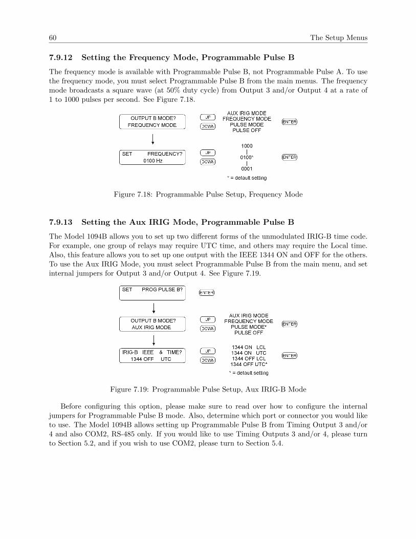
60 The Setup Menus
7.9.12 Setting the Frequency Mode, Programmable Pulse B
The frequency mode is available with Programmable Pulse B, not Programmable Pulse A. To usethe frequency mode, you must select Programmable Pulse B from the main menus. The frequencymode broadcasts a square wave (at 50% duty cycle) from Output 3 and/or Output 4 at a rate of1 to 1000 pulses per second. See Figure 7.18.
Figure 7.18: Programmable Pulse Setup, Frequency Mode
7.9.13 Setting the Aux IRIG Mode, Programmable Pulse B
The Model 1094B allows you to set up two different forms of the unmodulated IRIG-B time code.For example, one group of relays may require UTC time, and others may require the Local time.Also, this feature allows you to set up one output with the IEEE 1344 ON and OFF for the others.To use the Aux IRIG Mode, you must select Programmable Pulse B from the main menu, and setinternal jumpers for Output 3 and/or Output 4. See Figure 7.19.
Figure 7.19: Programmable Pulse Setup, Aux IRIG-B Mode
Before configuring this option, please make sure to read over how to configure the internaljumpers for Programmable Pulse B mode. Also, determine which port or connector you would liketo use. The Model 1094B allows setting up Programmable Pulse B from Timing Output 3 and/or4 and also COM2, RS-485 only. If you would like to use Timing Outputs 3 and/or 4, please turnto Section 5.2, and if you wish to use COM2, please turn to Section 5.4.

7.10 Set IRIG-B Main 61
7.10 Set IRIG-B Main
There are two separately-controlled IRIG-B outputs in the Model 1094B: “Set IRIG-B Main” and“Aux IRIG-B Mode.” Configure the main IRIG-B settings from this section, and auxiliary (AUX)IRIG-B mode from Section 7.9.13. In this way, you can set up two different time zones for IRIG-B,or you can independently turn the IEEE 1344 extension ON or OFF in either mode.
In the Model 1094B, IRIG-B is an electronic time code, synchronized to the GPS, that istransmitted each second. The four choices are (1) setting the time zone to UTC or Local, and(2) having the IEEE-1344 extension turned ON or OFF. To transmit the IRIG-B time code in theUTC time zone, the time will be offset from your local time determined by your locale. IEEE-1344extension increases the amount of information contained in the time code, including the two-digitdate and time quality. To use the IEEE-1344, your receiving equipment (e.g. relays, RTU’s, etc.)must be designed to receive the IEEE-1344 time code. See Figure 7.20.
NOTE: Make sure to set your main board jumpers correctly for each of the IRIG-B outputs.For information on setting the IRIG-B jumpers, see Section 5.2.
Figure 7.20: IRIG-B Configurations
For additional detail and definition on the different forms of IRIG-B, see Chapter 8, Timing,IRIG-B and Pulses.

62 The Setup Menus
7.11 Set Auto Survey
The Model 1094B GPS receiver uses an Auto Survey Mode that determines its position relative tothe available Global Positioning Satellites. It has two operating modes that are selectable from thefront panel or through either of the serial ports. These modes are (1) Power On Survey, (2) TurnOff Survey. See Figure 7.21.
Figure 7.21: Auto Survey Configurations
Once the survey has been started, the Model 1094B will indicate that it is locked to the GPS,and continue to refine the surveyed position. The survey may also be turned off at any time byselecting Turn Off Survey from the front panel.
The Auto Survey averages a total of 10,000 (slightly over 2 1/2 hours) valid 2D and 3D positionfixes. If the averaging process is interrupted, the averaging resumes where it left off when trackingresumes. Once the position is surveyed, the M12M timing receiver automatically enters the Position-Hold Mode. Once the antenna site has been surveyed in this manner, the user can expect a 2Dposition error of less than 10 meters with 95% confidence, and a 3D error of less than 20 meterswith 95% confidence.

7.12 Set Event/Deviation 63
7.12 Set Event/Deviation
The event inputs are used to time a signal received by the Model 1094B based on the internal timebase synchronized to the GPS. The accuracy of these timed events are within a microsecond witha resolution of 0.1 microsecond. See Figure 7.22.
A second feature is to use the event input to measure the deviation of a one pulse per second(1-PPS) signal.
Figure 7.22: Event Configurations
Note: If you are configuring for event capture, the next menu will allow you to clear any previouslystored events.
CLEAR EVENT DATA?YES:UP NO:DOWN
NOTE: Events may also be cleared using serial port 1 or 2. See Section 10.3.5
7.12.1 Technical Details of Event/Deviation Timing
For additional technical details on Event and Deviation timing, see Section A.3.5, Relay Contactsand Event Inputs. For information on setting the Event/Deviation jumpers on the main board, seeSection 5.5, Setting Internal Jumpers.

Chapter 8
Timing, IRIG-B and Pulses
8.1 Introduction
This section should help to identify specific terminology related to timing signals in the Model1094B, and clarify how to synchronize your external equipment, or IED’s. It should also answersome basic questions, such as:
• What are the different types of IRIG-B, and what are the differences?• How do you connect multiple devices to one 1094B timing output?• How far can you transmit timing signals?• What kind of cabling and connectors should I use?
The steps involved in getting your devices synchronized to the GPS are fairly simple and shouldnot take long to complete. To expedite the process, make sure that you know:
1. the type of timing signal each piece of equipment requires, and2. how to enable the equipment to receive the timing signal.
Sometimes, you will need to set a physical jumper, or configure it through the instrument setupprogram. Some equipment can auto detect the timing signal, so that nothing else is required, otherthan connecting the cable.
8.2 Timing Output Description
The rear panel of the Model 1094B includes a number of different types of connectors as illustratedin Figure 8.1. Starting from the right-hand side, there is a power inlet connector, a GPS antennaconnector, one event input connector, two DB-9 serial connectors, one SPDT relay connector andfour timing outputs. Except for the GPS antenna connector, each connector can have multiplefunctions. In the sections that follow, you should be able to understand each function to correctlyconfigure them.
8.2.1 Standard Inputs and Outputs
The 1094B has four separate outputs that can produce either digital or analog timing signals as de-scribed below. Digital signals include unmodulated IRIG-B, 1 Pulse per Second and Programmable

8.2 Timing Output Description 65
Figure 8.1: Rear Panel Description
Pulse; analog signals include modulated IRIG-B. Two of the outputs (3 and 4) can also source anindependent instance of IRIG-B or frequency of from 1 to 1000 pulses per second. Finally, eachdigital output can be configured as either 5 Volt CMOS/level shift, or 300 Volt FET.
8.2.2 Digital Drivers – 250 mA Per Channel
Each of the four timing outputs uses a separate FDC6333C, N & P-channel Power Trench Logiclevel MOSFET, for digital signals (e.g. unmodulated IRIG-B, 1 PPS and Programmable Pulse),capable of 250 mA at 5 Vdc. Together, these four outputs together can provide up to one ampof drive current at TTL/CMOS levels. This permits you to connect a large number of IED’sthat would draw up to that amount of current. For example, if the IED timing signal input (e.g.IRIG-B003) requires 10 mA, one output channel should be able to support 25 identical devices.
8.2.3 Analog Drivers
Each of the four outputs also has a separate analog driver to be used exclusively for modulated IRIG-B signals. The analog driver is an Analog Devices AD8532, single-supply, dual-output amplifier,which supplies a 4.5 Volt peak-to-peak (Vpp) signal through a 19.6-ohm source resistor. As theload current increases (by adding external IED’s), more voltage is dropped across the clock sourceresistor and the drive voltage decreases. Due to this change in peak-to-peak output, it is sometimesessential to match the modulated IRIG-B output voltage to the required IED input. Make sureto check the equipment specification and verify the input voltage levels. Table 8.1 shows how theactual drive voltage varies with increasing load current. For IED’s with a restricted input range, itmay be necessary to match the available drive voltage to the IED through a small dropping resistor.
Drive Current, mA Actual Drive Voltage, Vpp
0 4.5
1 4.48
10 4.3
100 2.54
Table 8.1: Drive Current vs. Voltage

66 Timing, IRIG-B and Pulses
8.3 Output Signal Description
The Model 1094B has four independent outputs subdivided into two groups: (1) Outputs 1 and2 can be configured for IRIG-B, 1 PPS or Programmable Pulse A; (2) Outputs 3 and 4 can beconfigured for IRIG-B, 1 PPS and Programmable Pulse B. Programmable Pulse A has two modes:ON and OFF. Programmable Pulse B adds to that two additional modes: Frequency and IRIG-B.Pulse mode is useful for timing individual pulses at specific intervals or at a specific time of dayor year. Frequency mode provides from 1 to 1000 pulses per second (Prog. Pulse B), at a 50%duty cycle. Programmable Pulse B may also be used as a second unmodulated IRIG-B configuredindependently from the standard IRIG-B.
Programmable pulse modes are similar to 1 PPS only they have an adjustable period and pulsewidth. Modes include, pulse per second, pulse per minute, pulse per hour, pulse per day, singletrigger (once per year), slow code and seconds per pulse.
8.3.1 IRIG-B Description
IRIG-B is a complete serial time code that occurs once per second and, depending on the config-uration, contains the day of year, hours, minutes, seconds, year and other important information.The Model 1094B transmits Format B with four variations as seen in Table 8.2. Note that with thenewer IRIG Standard 200-04, two of the designations have changed: the older B000 has becomeB004 and B120 has become B124.
Code, Old/New Signal Type Code Components
B000/B004* Pulse width code, No carrier BCDTOY , CF, SBS
B003** Pulse width code, No carrier BCDTOY , SBS
B120/B124* Sine wave, modulated, 1 kHz BCDTOY , CF, SBS
B123** Sine wave, modulated, 1 kHz BCDTOY , SBS
*IEEE 1344 ON, **IEEE 1344 OFF
Table 8.2: IRIG-B Time Code, Types Available
The IRIG-B time code consists of 100 bits produced every second, 74 bits of which containvarious time, date, time changes and time quality information of the time signal. Consisting oflogic ones, zeros and position identifier bits, the time code provides a reliable method of transmittingtime to synchronize various equipment.
There are three functional groups of bits in the IRIG-B time code, in the following order: BinaryCoded Decimal (BCD), Control Function (CF) and Straight Binary Seconds (SBS). The BCD groupcontains only time information including the seconds, minutes, hours and days, recycling yearly.The CF group contains other time-related information including year, time quality, leap year,pending leap seconds and parity. The SBS consists of the total elapsed seconds, restarting daily.Position identifiers separate the various components of the IRIG-B time code.

8.3 Output Signal Description 67
8.3.2 Modulated and Unmodulated IRIG-B
Figure 8.2 illustrates the primary differences between modulated and unmodulated IRIG-B. Youwill notice that the while modulated IRIG-B (B120) is distinctive because it uses a sinewave carriersignal of 1 kHz, it is similar to unmodulated IRIG-B (B000) since the peak-to-peak values of thecarrier follow the same form as the digital waveform, where the information is contained.
Figure 8.2: IRIG-B Waveforms
8.3.3 IRIG-B IEEE 1344 Extension
As mentioned above, the IEEE 1344 enables extra bits of the Control Function (CF) portion of theIRIG-B time code. Within this portion of the time code, bits are designated for additional features,including:
• Calendar Year (old method, now called BCDY EAR)• Leap seconds, and Leap seconds pending• Daylight saving time (DST), and DST pending• Local time offset• Time quality• Parity• Position identifiers
To be able to use these extra bits of information, relays, RTU’s and other equipment receiving thetime code must be able to decode them. Consult your equipment manual to determine if the IEEE1344 feature should be turned ON in the Model 1094B. To view details of the IEEE Std 1344-1995,please check with the IEEE.
NOTE: To download a copy of of the IRIG-B 2004 specification, please use the link to the Arbiterweb site.
http://www.arbiter.com/catalog/timing freq index.php and click on IRIG-B.
8.3.4 1 Pulse per Second (1 PPS)
A one Pulse-Per-Second timing output signal is very simple in concept. It is a digital bit transmittedevery second with a pulse width of 10 milliseconds. Probably the most critical part of this signalis that it is “on time” at the rising edge, compared with the signal from the Global Positioning

68 Timing, IRIG-B and Pulses
System (GPS). To produce a 1 PPS signal from the Model 1094B, use either Prog. Pulse A orProg. Pulse B. See Figure 8.2 for a comparison between unmodulated IRIG-B and 1 PPS.
8.3.5 Programmable Pulse (Prog. Pulse)
The Model 1094B has two independent programmable pulse functions: Programmable Pulse A andProgrammable Pulse B. Programmable Pulse A has a pulse mode that allows various pulse timingoptions from pulses each second up to one pulse per year. Programmable Pulse B has the same twomodes as Programmable Pulse A except that it has a Frequency Mode and Auxiliary IRIG Mode.The Programmable Pulse A and B feature set is shown in Table 8.3 below.
Other possible signals include controlling a 300-Volt FET for high-level signal handling with any ofthe available digital signals. The Programmable Pulse feature also has an adjustable pulse widthin 10 millisecond increments from 10 milliseconds to 10 minutes in duration.
Programmable Pulse Function Prog Pulse A Prog Pulse B
Pulse Per Second yes yes
Pulse Per Minute yes yes
Pulse Per Hour yes yes
Pulse Per Day yes yes
Single Trigger yes yes
Slow Code yes yes
Frequency Mode no yes
Aux IRIG Mode no yes
Table 8.3: Programmable Pulse Output Functions
8.3.6 Programmable Pulse with 300-Volt FET, Setup
With this setting you can perform high-level switching at any of the four timing outputs, settingthe 1094B to trigger a pulse at the required time of day or time interval. Connect a voltage ofup to 300 volts and pull down a signal with the Open Drain 300-Volt FET. Remember to connectthe FET with suitable protection against overvoltage transients and over current conditions. Toset timing output jumpers for programmable pulse with 300-Volt FET, see Section 5.2. Next, youwill need to configure the type of programmable pulse through the Setup Menus. See Section 7.9for more details on setting up the programmable pulse through the Setup Menus. ProgrammablePulse features may also be set up remotely using 1094 Utility through either serial communicationport. For setup using 1094 Utility, see Section 6.6.8 or Section 6.6.9.
8.3.7 300-Volt FET Connection – Setup and Protection
For setup diagrams see Appendix D, External Switching Applications. Open-drain outputs haveinternal protection against over-voltage. Maximum peak ratings are 10 A and 400V. Externalprotections (current-limiting resistors, surge suppression diodes, snubbers, etc.) must be provided

8.4 Connecting Outputs 69
by the user, if required, to ensure that maximum ratings are not exceeded even momentarily. Also,before using the 300-Volt FET, please check the data sheet of the IRF740S used in this application.
8.4 Connecting Outputs
The Model 1094B comes equipped with two types of output connectors: BNC female and screwterminals. BNC connectors are compatible with most coaxial cables. Terminal connectors arecompatible with twisted pair cabling, in which the wires are stripped bare, tinned and fixed intothe correct screw terminal positions.
NOTE: If using a shielded, twisted-pair cable (like Belden 8760), DO NOT connect the cable shieldat the clock. Always connect a cable shield at the receiving equipment (IED) grounding point.
8.4.1 Attaching Cables to Screw Terminals
Prepare the twisted pair cable by stripping back at least 1/4 inch of the insulation and any shielding.DO NOT tin the bare wire with solder. Tighten the screws down on the wire. Do not ground theshield to the Arbiter clock.
8.4.2 How Far Can I Run IRIG-B Cabling?
Some important considerations for transmitting IRIG-B over long distances are: (1) resistive lossesin cabling, (2) electromagnetic interference, (3) propagation delays and (4) installation and main-tenance costs.
For details on distributing IRIG-B signals over long distances, see application note, AN101, Dis-tributing Timing Signals in a High-EMI Environment. Download file appnote101.pdf at the follow-ing link:
http://www.arbiter.com/ftp/datasheets/
For important considerations about IRIG-B connections, distribution of signals and accuracy, down-load the file, IRIG-B accuracy and connection requirements.pdf at the following link:
http://www.arbiter.com/ftp/datasheets/.
8.4.3 Synchronizing Multiple Devices From One Masterclock Output
In many installations, master clock signals (e.g. the 1094B) are “fanned out” to a number of devices.This method makes more efficient use of the clock synchronizing capability since the clock driversare designed to handle multiple loads. The exact number of possible loads must be determinedfrom the input impedance of each connected IED, which sets the current drawn from the specific1094B output. In calculation 8.1, the device current (I) is calculated from the output voltage (V)and the input impedance (Z) of the IED, which is 5 kilohms.
(8.1) I = V/Z = 5 V olts/5000 Ohms = 0.001 Amps(1 mA)
If you were to connect ten of the same devices to the same output, then the total current drawnwould be 10 x 0.001 A = 0.01 A (10 mA).

70 Timing, IRIG-B and Pulses
8.4.4 Connecting Unmodulated IRIG-B
To drive multiple loads from a single 1094B timing output, make sure they are wired in parallel.Some call this “daisy-chaining”, however the idea is to drive all of these loads in parallel from thesingle output. It is much simpler to connect loads to unmodulated IRIG-B than for modulated.This is because all of the loads are driven at the same voltage and each draws current directly fromthe transmission line.
To determine capacity for Unmodulated IRIG-B, follow these steps:
1. determine the impedance (or resistance) of each connected load2. divide the drive voltage (5 V) by the resistance of each device3. sum up all the load currents for the total current for one clock output4. the total current should not exceed 250 mA.
Another method is to determine the lumped impedance of all of the connected IED’s in parallel.Then, determine the overall current by dividing the drive voltage (5 V) by the computed lumpedimpedance value. This current should not exceed 250 mA.
Techniques for Lightly Loaded Outputs
For lightly loaded outputs, you may want to consider intentionally loading down the output witha resistor. This technique tends to calm any overshoot and ringing that would otherwise occurwithout it. For example, placing a 50-Ohm resistor across the load would increase the outputcurrent by 100 mA, however it would require a resistor that would handle that load. Considerusing at least a 1-Watt resistor in this example. Two possibilities exist: (1) placing a loadingresistor across the load itself, and (2) placing a source resistor in series, at the output of the clock.A source (series) resistor would also tend to drop the available voltage to the device, so make surethat the voltage is adequate with suggestion #2.
8.4.5 Connecting Modulated IRIG-B
The total load capacity for the modulated IRIG-B driver depends on the type and number ofloads. The main difference in computing the load capacity for modulated IRIG-B and unmodulatedIRIG-B is that modulated IRIG-B decoders tend to be sensitive to the peak-to-peak voltage. Withadding loads, the 1094B modulated driver produces more current, which is passes through theinternal source resister, dropping the available output voltage. The open circuit voltage (i.e. noloads) is approximately 4.5 Vpp, so any connected loads will cause the available voltage to drop.The available output voltage (Vpp) with a known current is calculated in 8.2.
(8.2) V pp = 4.5 V pp− I(19.6 Ohms)
Therefore, if you had 10 mA of load current (I load) the available voltage (Vpp) would be 4.304Vpp. If the load current equals 100 mA, then the available voltage would be 2.54 Vpp. So, youcan see how the increasing load current (i.e number of loads) affects the available drive voltage atthe clock output. See also Table 8.1.

8.4 Connecting Outputs 71
8.4.6 Wire Losses
Another factor affecting the available voltage is the resistive losses through the cabling. Wire has acertain resistivity associated with it that is determined by its metallic composition, and resistancedetermined by the diameter and length. For example, single-strand, 22 AWG (bare, enamel-coated)copper wire has a resistance of approximately 16.2 ohms per 1000 feet. To compute the loss wemust include both wires in the connection, signal and return. For coaxial cabling, the resistance ofthe center conductor is rated differently than the shield. For a twisted pair, both of them shouldessentially have the same resistance per cut length. If we use a twisted pair of 22 AWG (copper asabove), then the available voltage (at 100 mA of current) for 500 feet of wire including the sourceresistor is calculated in 8.3.
(8.3) V pp available = 4.5− I(19.6 source)− I(16.2 wire) = 0.92 V pp
So, you can see that most of the drive voltage is lost with 100 mA of current and 500 feet of 22AWG twisted pair transmission line, including the losses at the source resistor. The decoder inmost IED’s may very likely not detect the signal at 0.92 Vpp. Remember to make your cableruns as short as possible, to use a larger diameter cable, and to carefully distribute the loads. Forexample, the resistance for 18 AWG (bare, enamel-coated) copper wire is 6.38 ohms per 1000 feet.
8.4.7 Voltage Matching for Modulated IRIG-B
With modulated IRIG-B, it was mentioned that certain decoders are very intolerant of drive voltagevariation. If the IED specification says that the acceptable voltage range is 3.3 Vpp +/- 0.5 volt,and the available voltage is high, then you must reduce the voltage using a dropping resistor. Thevalue of the dropping resistor is determined by dividing the difference voltage by the device current.For example, suppose that the available voltage is 4.5 Vpp, the (nominal) acceptable voltage is 3.3Vpp, and the device current is 10 mA. Determine the dropping resistor value (shown in 8.4).
(8.4) R drop = V difference/I device = (4.5− 3.3)/0.01 = 120 Ohms
The Power dissipation (P) is calculated in 8.5.
(8.5) P = I2R = (0.01)2(120) = 0.012 Watts
An eighth-watt resistor should work fine.
For a voltage that is too low, then the modulated IRIG-B signal level must be increased by someother means, such as (1) distributing the load differently to reduce the current (raising the availablevoltage), (2) increase the wire size, or (3) by using a distribution amplifier.
8.4.8 Cable Delays
Electromagnetic waves travel at the speed of light (C) in free space or vacuum and a fraction ofthat through cabling. The speed of an electromagnetic wave in free space is given by Constant 8.6.
(8.6) C ≈ 9.84(108) feet/second

72 Timing, IRIG-B and Pulses
Since electromagnetic waves travel slower through any cable, cable manufacturers normally specifycable with a velocity factor (VF), which is a percentage of the speed of light in free space, andcharacteristic of the specific cable. The Velocity Factor for the RG-6 cabling used by ArbiterSystems for GPS antenna connections, is about 83% of C. Most transmission lines have velocityfactors in the range of 65% to 97%. Using these values you can determine the actual time delay inyour cable distribution system and compare it to your required accuracy. As an example, it wouldtake 840 feet of RG-6 cable (with a velocity factor of 83%) to delay the signal by one microsecond.For IRIG-B timing applications, these delays may not be important, compared to other criteria.Otherwise, you would be forced to compensate for the time delay using another method, such asadvancing the timing output or placing another master clock at the remote site.
8.4.9 Solutions
There are many solutions to providing an accurate timing signal in distant locations. However, themost satisfying solution may not be to string cabling for hundreds of meters. The costs associatedwith installing and maintaining cabling over a wide area may be unsatisfactory. Since the GPSis so pervasive, it may prove to be less costly to install another clock at a distant location, whichwould also improve accuracy and provide redundancy. Before installing cabling over a wide area,be sure to first examine all the possibilities.

Chapter 9
Relay Contacts and Event Inputs
9.1 Introduction to Relay Operation
The Model 1094B has one set of mechanical, Form C relay contacts that may be configured toswitch with a predetermined fault, an out-of-lock condition, or driven by the programmable pulsefeature. When configuring the 1094B relay contacts for programmable pulse, take care to comparethe pulse rate with the life expectancy of the contacts. See Programmable Pulse in the Index fordetails on configuring the Model 1094B for programmable pulse.
9.2 Configuring
To configure these contacts, you will need to remove the cover to the clock chassis locate jumperJMP8. It is located just slightly left of center. See Section 5.3 for more information on configuringthese jumpers.
9.3 Fault Conditions
If the FAULT LED illuminates, the clock status message will change to read:
CLOCK STATUSERROR messageWhere message = one of the error messages listed below.
1. Receiver Failure (no communication between clock and GPS Receiver)2. Antenna Short (antenna voltage is very low; it is normally 5 Vdc)3. Antenna Open (antenna not drawing any current)
9.4 Viewing the Fault Status
If the Model 1094B executes a fault due to one of the conditions listed above, it will display theClock Status fault condition on the LCD and illuminate the Fault LED. The fault status will alsobe available using the Event Status commands through either of the serial communications ports.See Section 10.3.4, Serial Communication and Command Set, for details on using the serial port toconfigure and access the event information.

74 Relay Contacts and Event Inputs
9.5 Connecting to the Multimode Relay
When connecting the 1094B multimode relay, do not exceed the ratings and specifications. Fig-ure 9.1 below illustrates the 5-mm spaced terminals on the connector plug for fastening wiring.Normal procedure is to strip the wire by one-fourth inch or more; DO NOT tin with solder priorto attaching to the connector plug. Tighten the set screw clockwise to secure wires.
Figure 9.1: Rear Panel Relay Contact location and Connector Plug
9.5.1 Relay Contact Operation
The information below gives the contact condition for two states: (1) Fault, or Power OFF and,(2) No Fault. Silkscreen in Figure 9.1 indicates a Faulted or Power OFF condition.
• Fault, or Power Off – Left to Center pin open (NO), Center to Right pin shorted (NC).• No Fault and Power On – Left to Center pin shorted, Center to Right pin open.
9.6 Introduction to Event Inputs
This section should provide more detail on the operation of the event inputs on the 1094B. Toconfigure the event capture settings, see Section 5.5, Configuring Event Input Jumpers, and Sec-tion 7.12, Set Event/Deviation.
9.7 Event Timing Inputs
The Model 1094B provides one dual-function event input channel with 1-microsecond resolutionat three possible input connectors: dedicated event input connector, COM1 or COM2. The eventinput channel may be used to time an input signal or continuously measure the 1-PPS deviation.
Data for individual recorded events can be recalled using either the Event/Deviation front panelkey or via the RS-232C interface (see Section 10.3.5). Data for each event will be retained until it isretrieved using one of these two methods. Thus, if no event data points are retrieved or broadcast,recording will be suspended when the total number of events reaches 300. As soon as data isretrieved for a recorded event, its address (001 to 300) is made available for data corresponding toa new incoming event.
9.7.1 Event Timing – Latency
Event data are recorded using a high-speed capture circuit operating with a 96 MHz time-base.Latency is limited by the interrupt processing speed of the clock’s microcontroller, which in turndepends on its workload at the time the event is received. Since the workload varies from time
9.7 Event Timing Inputs 75
to time, latency likewise varies. However, response time will, in general, never be less than a fewhundred microseconds nor greater than 10 milliseconds.
9.7.2 Deviation Measurement
The event input can also be configured to display measured event times as 1 pulse-per-second (1PPS) deviation measurements. The intended purpose of the deviation measurement function is toallow comparison of an external 1-PPS signal to the clock’s precision internal 1-PPS signal. Theclock determines the mean time difference between the two signals, which can be displayed on thefront panel or collected through either COM1 or COM2.
9.7.3 Measurement Principle
The measurement technique employed for 1-PPS Deviation uses the same time determination andrecording scheme used for Event Time measurement (refer to paragraph above), but makes theassumption that the input signal is periodic and continuous. Also, the operation of the circularmemory buffer is modified somewhat, in that recording does not stop after the first 300 events;new event data is given priority over existing data, and will overwrite it. Since the incoming signalis at 1 Hz and the circular buffer holds 300 events, each event time record will be overwritten onceevery 300 seconds.
Once every second the processor looks at the most recent group of 16 events. To compute devi-ation, it uses only the portion of the event data describing fractional seconds (e.g. values between0.0000000 and 0.9999999). The 16 fractional-second values are normalized around 0.0000000, sothat the range of results from the deviation computations will be centered on zero (± 0.5 seconds).It also computes the statistical Mean and Sigma (Standard Deviation) values on the 16 values,which are then be displayed on the front panel or output via either COM1 or COM2.
9.7.4 Event Timer Input Channel Configuration
Adjustments to both the hardware and firmware configuration are required for the Model 1094B toreceive input signals and to record events. The hardware configuration is described in Section 5.5,where jumpers JMP2 and JMP3 are identified. Discussion of the configuration through firmwarefollows in this section and in Section 10.3.5.
9.7.5 Configuring Event/Deviation Operation
There are two methods for configuring the Model 1094B for either event recording or 1 PPS devia-tion measurement: (1) through the front panel interface, and (2) through COM1 or COM2 RS-232serial ports.
Configuring Event/Deviation Mode from Front Panel Interface
Press the SETUP key repeatedly until you reach the menu item that states:
SET EVENT/DEVIATION?
Press ENTER and the display should read,

76 Relay Contacts and Event Inputs
EVENT OR DEVIATION?EVENT SELECTED
The second line may also display “DEVIATION”. Press the UP or DOWN key to change to thedesired mode and press the ENTER key.
Configuring Event/Deviation Mode from COM1 or COM2
Use the m,nEV command to configure the Event/Deviation function to either event recording or1 PPS deviation measurement. For example, “0ev” configures the 1094B to the Event Mode, and“1ev” configures the 1094B to the Deviation Mode. For command reference, see Section 10.3.5.
9.7.6 Accessing or Displaying Event Data
Displaying Data on the Front Panel
Event and Deviation data can be accessed from either the front panel, COM1 or COM2.The following paragraphs describe the steps required to access data using the front panelEVENT/DEVIATION key. When pressing the EVENT/DEVIATION key, the display will en-ter a circular scroll, which begins by showing the data if any is present. The readout will displayone of the event times (001 to 300), using the following format:
EVENT nnnddd:hh:mm:ss.sssssss
Where:”nnn” = event number (001 to 300)”ddd” = day of year of the event (1 to 366)”hh” = hour of the event (00 to 23)”mm” = minute of the event (00 to 59)”ss.sssssss” = second and fractional seconds of the event
Press the UP or DOWN key to scroll the display through all events presently stored in theevent time buffer. When you exit and then re-enter the event display mode, it will display the sameevent record number as when you exited. However, the data itself may be changed if it has beenoverwritten. Note that viewing an event on the front panel marks its position as available to beoverwritten up to the event currently being viewed, but not after.
Accessing Data From COM1 or COM2
Access individual event data through COM1 or COM2 using the two serial commands, nED orEV. Use nED, with n = 1 – 300, to view a specific event by number. For example, type “29ed”to view event number 029. Type “198ed” to view event number 198. Use EV repeatedly to scrollup through the event buffer beginning at record 001. For example, type “ev”, “ev” and you willsee record 001 and 002. If you send “ev” later, it will begin at record 003. Full details on thesecommands are located in Section 10.3.5.

9.7 Event Timing Inputs 77
Setting Event Channel Time
Set the event recording time to either UTC or Local by using the nTA command. For example,“0ta” sets the event time to UTC, and “1ta” sets the event time to Local.
Status of Event or Deviation
Use the SA command to determine the status of these functions. If you have configured the 1094Bfor event mode, send “sa” to return the read (R) and write (S) pointers. This tells you the currentstate of reading and writing in the event buffer. For example, typing “sa” returns the followingresponse:
E R=004 S=026
This tells you that (1) the 1094B is set for Event recording, (2) the current “read” pointer is atevent record 004 (when using the EV command), and (3) that there have been 26 records writtento the event buffer. The “R” value (read index) does not automatically update on the display whileevents are being recorded.
9.7.7 Clearing Events
There are two ways to clear events from the Model 1094B event buffer: (1) through the front panelkeys, and (2) through either COM1 or COM2 RS-232 connections. “Clearing” means to completelyremove all 300 records at one time. This is different than viewing data on the display or viewingdata through COM1 or COM2, which actually “marks” the individual event as having been “read”and may be overwritten with any new data. New events may only be overwritten if you view themsequentially, counting from Event 001.
Viewing individual event data on the front LCD panel, or through either COM1 or COM2,marks them as available to be overwritten. For example, if you look at records 1 – 10, and eventsare occurring while viewing these records, they will be overwritten. Assuming the event buffer isfull, and you are viewing data from records 15 – 20 through COM1 or COM2, events will not beoverwritten until you also view records 1 – 14. Viewing events includes retrieving event recordsover COM1 or COM2.
Clearing Events from the Front Panel
To clear all recorded events stored in the event storage buffer, press the SETUP key until you reachthe menu that says,
SET EVENT/DEVIATION?
Press ENTER and the display should read,
SET EVENT/DEVIATION?EVENT SELECTED

78 Relay Contacts and Event Inputs
Press ENTER and the display should read
CLEAR EVENT DATA?YES:UP NO:DOWN
Clearing Events Using Serial Commands
Type or send “0,123ev” or “1,123ev” to immediately clear all events stored in the event buffer. SeeSection 10.3.5.
Clearing Events Using the 1094 Utility
Using the 1094 Utility, first connect to the Model 1094B and select Unit > Clear Events, or clickthe Clear Events button. See Section 6.6.4.

Chapter 10
Serial Communication and Commands
10.1 Introduction
The Model 1094B has two RS-232/485 ports, called COM1 and COM2. COM1 combines thetwo functions of RS-232 and RS-485 at one DB9M connector (J5), and COM2 combines the twofunctions of RS-232 and RS-485 in a separate DB9M connector (J7). The RS-232 ports do not useflow control, and the RS-485 ports function in transmit only mode.
Use the two serial ports interchangeably for separate functions. You may wish to interrogate theclock on one port for basic information (i.e to configure something) and at the same time be ableto have the second serial port broadcasting a specific time code to a meter. While most recentsubstation equipment has standardized on the IRIG-B time code, some devices are designed toreceive ASCII data through the serial port. Another common serial-port function is to connect adigital wall display to indicate the time.
10.2 Communication Port Information
Table 10.1 lists functions and associated pins for both the RS-232 and RS-485 ports.
Pin No. Function Pin No. Function
1 Not Connected 6 RS-232 Input
2 RS-232, Rx Data 7 Not Connected
3 RS-232, Tx Data 8 RS-422/485, Tx-A
4 RS-232 Output/Prog Pulse 9 RS-422/485, Tx-B
5 Ground – –
Table 10.1: COM1 and COM2 Pin Definitions

80 Serial Communication and Commands
10.3 Command Set
This section provides information for controlling and communicating with the Model 1094B viathe RS-232C serial interface. All off the RS-232 commands are functionally grouped into similarcategories. For example, Section 10.3.11 lists all of the commands used to both set and retrieve thedate and time in one of the standard formats.
Each command name and syntax is highlighted in bold at the first line of each definition. De-tailed information used to interpret the commands and responses follows each command heading.Sometimes the command is very short, such as the command to return the Local Time: TL.Other commands require a prefix before the letter command to specify them, such as to broadcast:m,n,o,pBR. For example, the command to start the ASCII Standard broadcast string at a rate ofonce per second, on Local time, from COM1 is 1,1,1,0BR.
When a command requests information from the 1094B, it returns the most current data available.Numeric data is returned as an ASCII string of numeric characters, with leading sign and embeddeddecimal point as needed. Strings are terminated with carriage return and line feed characters.Enter any RS-232C command as written in these tables without pressing ENTER. Characters areautomatically entered when typed. If including any of these commands in a programming sequence,do not include any carriage-return or line-feed characters.
The following symbols and syntax are used throughout and are repeated here for emphasis:
C= Shorthand for carriage-return, line-feedU = UTC TimeL = Local Timesoh = An ASCII character (start of header) = Hex 01bel = An ASCII character = Hex 07n = integer used for various numerical values (e.g. nnn in minutes)yyyy = four digit yearddd = Julian day-of-yearmm = monthhh = hourmm = minutess = second
Underlines are used for clarity only and graphically represents the location of ASCII spaces.
10.3.1 Configuring Custom Broadcast Strings
The Model 1094B has two custom strings (A and B) available for you to configure. Use the@@A. . . or @@B. . . to define and install the new string. Three elements are available for buildingup a custom string: characters, true/false conditions and ordinal conditions. Table 10.2 lists all ofthe available characters for you to build up your special string. True/False condition statementsprovide some logic in the output. Ordinals enables you to view levels of measurement basedon the command statements; for example you might want to indicate a level of accuracy in thestring. Examples follow to illustrate how some of the standard strings look using the characters inTable 10.2, true/false statements and ordinal statements.

10.3 Command Set 81
Custom String Command
Command: @@A . . . , @@B . . .
Use @@A . . . to create a Channel A broadcast, and @@B . . . to create a Channel B broadcast string.This includes start of header (Hex 01), time, date, carriage-return, and other required features. Ina sense, it allows you to create a custom broadcast string. These characters and definitions arelisted in Table 10.2 below, along with custom string examples.
Custom Broadcast Characters
Character Meaning
// / character/Cssnn Xor checksum of specified range, where ss =
start location (hex value from 00 to FF) and nn= number of bytes (hex value from 00 to FF)
D Day of month (1, . . . , 31)d Day of year (001, . . . , 366)e GPS elevation (±dddddd.dd length = 10)f Fractional Seconds (00, . . . , 99)
/Hxx Hexadecimal value where xx is a hex value from00, . . . , FF
h Hour (00, . . . , 23)m Minute (00, . . . , 59)M Month (1, . . . , 12)O Local hour offset (±hh where hh=0, . . . , 12)o Local minute offset (0, . . . , 59 minutes)Pi Latitude where i = 1, degrees (dd); = 2, Min-
utes (mm); = 3, Fractional minutes (mmmm); =4, Seconds (ss); = 5, Fractional seconds (fff); =6, N (North) or S (South)
pi Longitude where i = 1, Degree (ddd); = 2,Minutes (mm); = 3, Fractional minutes(mmmm); = 4, Seconds (ss); = 5, Fractional sec-onds (fff); = 6, E (East) or W (West)
r Carriage return and line feedSii String Type where ii: 01 = Status change (re-
ceiver out of lock, antenna short, antenna open)s Seconds (00, . . . , 59)
Txx On time character where xx is a hex value from01 to FF (Note: Must be at the start or end of thestring!)
U Unlock time (00, . . . ,99 minutes)W Day of week (1, . . . , 7 where 1 = Sunday)w Day of week (1, . . . , 7 where 1 = Monday)y Year (00, . . . , 99)Y Year (2000, . . . , 2xxx)
Table 10.2: Custom String Character Table

82 Serial Communication and Commands
Table 10.2 Notes Conditionals can use any of the above, with the exception of /Cssnn and Txx,in addition to any string characters. CONDITIONALS CANNOT BE NESTED!
True/False Condition
Command: /[ii? < t > / :< f > /]where:< t > = True condition< f > = False conditionii: 01 = Locked; 02 = Status change; 03 = Locked with max accuracy; 04 = Fault; 05 = DaylightSaving Time change pending
Ordinal Condition
Command: /ii? < 0 > / :, . . . , < n > /;< e >where:< 0 >,< 1 >, . . . , < n > = ordinal position< e > = Else conditionii: 01 = Time Quality (13 possible ordinals); 02 = Time Zone Indicator (3 possible, 0=DSTactive, 1=Not active, 2=UTC)
String Setup Examples
The examples listed below illustrate how various strings are specified using the @@A . . . or @@B. . . commands. In order to create your own custom string, you will need to type in charactersfrom Table 10.2, including any conditionals (as noted above) immediately after @@A or @@B. Theexample command below shows how to configure COM1 with the ASCII Standard broadcast fromthe 1094B using a terminal window.
Sample Command for ASCII Standard: @@A/T01/d:/h:/m:/s/r
Standard Broadcast Strings
Interrogate Broadcast off:
ASCII Standard: /T01/d:/h:/m:/s/r
Vorne Standard: 44/h/m/s/r55/d/r11/U/r/T07
Status: /[02?/d:/h:/m:/s /S01/r/:/]
Ext. ASCII (DTSS MSG): /T0D/H0A/[03? /:?/]/y /d:/h:/m:/s.000
ASCII + Quality: /T01/d:/h:/m:/s/01? /:./:∗/:#/;?//r
ASCII + Year: /T01/Y /d:/h:/m:/s/01? /:./:∗/:#/;?//r
Return Custom String – mCB
To return a custom string installed in the Model 1094B, use the mCB command, where m = 0 forCustom 1 and m = 1 for Custom 2.

10.3 Command Set 83
10.3.2 Broadcast Mode Overview
Command Explanation
Broadcast strings are controlled by using the command m,n,o,pBR, where m = 0 to 16, andincludes the following broadcast messages:
0, INTERROGATE MODE 9, NMEA183ZDA1, ASCII STD 10, ABB SPA MSG2, VORNE STD 11, DISPLAY BUFFER3, EVENT DATA 12, PATEK PHILIPPE MSG4, STATUS 13, KISSIMMEE MSG5, EXT. ASCII 14, NGTS6, ASCII + QUAL 15, CUSTOM 17, YEAR + ASCII 16, CUSTOM 28, NMEA183GLL
n = the update rate, from 0 to 9999 seconds; o = the Time Zone, where 0 = UTC and 1 = Local;p = the COM port, where 0 = COM1 and 1 = COM2
Broadcast Example
Set the 1094B to broadcast the Vorne Std output at a rate of once per second, in Local time fromCOM1.
Send: 2,1,1,0BR
To turn off a broadcast, Send: 0BR, for COM1, or 1BR, for COM2.
Returned Settings
After sending certain commands to configure the Model 1094B, the clock will return the newsettings to the computer or terminal. For example after sending 2,1,1,0BR, the clock will returnthe following:
Returned: m:02 n:0001 o:01 p:00
10.3.3 COM Port Settings
Set COM Port Settings
Command: 2,b,w,s,p,cYB
Sets the COM port settings as follows:
b = baud rate: 0 = 1200, 1 = 2400, 2 = 9600, 3 = 19200, 4 = 38400; w = word length: 0 = 7bits, 1 = 8 bits; s = stop bits: 0 = 1 bit, 1 = 2 bits; p = parity: 0 = off, 1 = even, 2 = odd; c =COM port: 0 = COM1, 1 = COM2.

84 Serial Communication and Commands
10.3.4 Broadcast Commands
Broadcast Mode – INTERROGATE (OFF)
Command: 0BR, 1BR
0BR deactivates the RS-232C Broadcast Mode (resets to Interrogate Mode) on COM1. 1BR de-activates the RS-232C Broadcast Mode on COM2. m,n and o are not necessary to turn off thebroadcast from either COM port.
Response: C
Broadcast Mode – ASCII STD
Command: 1,n,o,0BR, 1,n,o,1BR
1,n,o,0BR configures the 1094B to broadcast the time-of-day as ASCII standard data on COM1.1,n,o,1BR configures the 1094B to broadcast ASCII standard data on COM2. Set n equal to thedesired broadcast interval (in seconds) and o according to the desired time zone (UTC or Local),where o = 0 for UTC and o = 1 for Local.
Response: <soh>ddd:hh:mm:ssC
Broadcast Mode – VORNE STD
Command: 2,n,o,0BR, 2,n,o,1BR
2,n,o,0BR configures the 1094B to broadcast from COM1 data formatted for Vorne large formattime displays. Refer to Arbiter Systems Application Note 103 for more information. 2,n,o,1BRconfigures the 1094B to broadcast Vorne-formatted data on COM2. Set n equal to your desiredbroadcast interval (in seconds) and o according to the desired time zone (UTC or Local).
Response:44hhmmssC(UTC/Local Time)55dddC(day of year)11nnC(out-of-lock time)bel (bel = Hex 07; sounds at the end of the time code)
Response (broadcast interval depends on n; the number and order of strings returned depend uponoptions ordered with clock, for example Option 28):
Data is transmitted ahead of time, and the bel character is transmitted on time. When properlyconfigured, the Vorne displays update simultaneously upon receipt of the bel character.
Broadcast Mode – EVENT DATA
Command: 3,n,o,0BR, 3,n,o,1BR
3,n,o,0BR configures the 1094B to broadcast from COM1 any event data at the time it is recorded.3,n,o,1BR configures the 1094B to broadcast from COM2 any event data at the time it is recorded.n is ignored and o determines whether the event time is either UTC (o=0) or Local (o=1).
10.3 Command Set 85
Response:Local mm/dd/yyyy hh:mm:ss.sssssss nnnLCUTC mm/dd/yyyy hh:mm:ss.sssssss nnnUC
Where:nnn = Event-Buffer Read Index NumberU = UTC TimeL = Local Time
Broadcast Mode – STATUS
Command: 4,n,o,0BR, 4,n,o,1BR
4,n,o,0BR configures the 1094B to broadcast any status data from COM1 when it changes.4,n,o,1BR configures the 1094B to broadcast any status data from COM2 when it changes. nand o are ignored. NOTE: When a valid fault is detected, the specific status fault is broadcast(with Julian day, and time) to the chosen serial port once. When the fault clears, another messageis sent describing the cleared fault.
Response with fault:
ddd:hh:mm:ss OUT OF LOCK C
Other messages: “ANTENNA OPEN” or “ANTENNA SHORT” or “RECEIVER FAILURE”
Response when fault clears:
ddd:hh:mm:ss LOCKED C
Other messages: “ANTENNA OK”, “RECEIVER OK”
Broadcast Mode – EXT. ASCII
Command: 5,n,o,0BR, 5,n,o,1BR
EXT. ASCII (or Extended ASCII) and adds a time quality indicator to the end of the StandardASCII time string. 5,n,o,0BR configures the 1094B to broadcast from COM1 the time-of-day asASCII using an extended format prefaced with a time quality indicator (Q). 5,n,o,1BR configuresthe 1094B to broadcast the same data from COM2. The start bit of a carriage-return is transmittedon time. Set n equal to your desired broadcast interval (in seconds), o according to the desiredtime zone (0 = UTC, or 1 = Local).
Response:CQ yy ddd hh:mm:ss.000
Format:C= Carriage-return, line-feed.Q = Time quality indicator, and may be represented by:(a space) = meaning it is locked with maximum accuracy.? = (ASCII 63) unlocked, accuracy not guaranteed
= used for clarity only and graphically represents the location of ASCII spaces.

86 Serial Communication and Commands
Broadcast Mode – ASCII + QUAL
Command: 6,n,o,0BR, 6,n,o,1BR
ASCII + QUAL means Standard ASCII plus Time Quality Indicator. 6,n,o,0BR configures the1094B to broadcast from COM1 the time-of-day as ASCII data appended with a time qualityindicator. 6,n,o,1BR configures the 1094B to broadcast from COM2. Set n equal to your desiredbroadcast interval (in seconds) and o according to the desired time zone (0 = UTC or 1 = Local).
Response:<soh>ddd:hh:mm:ssQC
Format:soh = Hex 01 – the start bit of the soh character is transmitted on time.Q = Time quality indicator. may be represented by:space = locked, maximum accuracy. = (ASCII 46) Error < 1 microsecond* = (ASCII 42) Error < 10 microseconds# = (ASCII 35) Error < 100 microseconds? = (ASCII 63) Error > 100 microseconds
Broadcast Mode – YEAR + ASCII
Command: 7,n,o,0BR, 7,n,o,1BR
YEAR + ASCII is the same as ASCII plus Time Quality Indicator adding the four-digit year tothe beginning of the string. 7,n,o,0BR configures the 1094B to broadcast from COM1 the yearand time-of-day as ASCII data appended with a time quality indicator. 7,n,o,1BR configures the1094B to broadcast from COM2. Set n equal to your desired broadcast interval (in seconds) and oaccording to the desired time zone (0 = UTC or 1 = Local).
Response:<soh>yyyy:ddd:hh:mm:ssQC
Format:soh = Hex 01 – the start bit of the soh character is transmitted on time.Q = Time quality indicator. may be represented by:space = locked, maximum accuracy. = (ASCII 46) Error < 1 microsecond* = (ASCII 42) Error < 10 microseconds# = (ASCII 35) Error < 100 microseconds? = (ASCII 63) Error > 100 microseconds
Broadcast mode - NMEA183GLL
Command: 8,n,o,0BR, 8,n,o,1BR
8,n,o,0BR configures the 1094B to broadcast the National Marine Electronics Association Standard(NMEA - 0183) to broadcast from COM1. 8,n,o,1BR configures the 1094B to broadcast the same

10.3 Command Set 87
standard from COM2. Set n equal to your desired broadcast interval (in seconds) and o accordingto the desired time zone (0 = UTC or 1 = Local).
GLL - Geographic Position, Latitude-LongitudeLatitude and Longitude of present vessel position, time of position fix and status.Response:
$–GLL,llll.llll,a,yyyyy.yyyy,a,hhmmss.sss,ACWhere:
GLL = Geographic Position, Latitude / Longitudellll.llll = Latitude of positiona = N or Syyyyy.yyyy = Longitude of positiona = E or Whhmmss.sss = UTC of positionA = status: A = valid data
Broadcast Mode - NMEA183ZDA
Command: 9,n,o,0BR, 9,n,o,1BR
9,n,o,0BR configures the 1094B to broadcast the National Marine Electronics Association Stan-dard (NMEA - 0183) to broadcast from COM1. 9,n,o,1BR configures the 1094B to broadcast thestandard from COM2. Set n equal to your desired broadcast interval (in seconds) and o accordingto the desired time zone (UTC or Local).
ZDA - Time & DateUTC, day, month, year, and local time zone.Format: $–ZDA,hhmmss.ss,dd,mm,yyyy,xx,xxCWhere:
ZDA = Time and datehhmmss.ss = Time in UTCdd = Day, 01 to 31mm = Month, 01 to 12yyyy = Yearxx = Local zone description, 00 to +/- 13 hoursxx = Local zone minutes description (same sign as hours)
Broadcast Data – ABB SPA MSG
Command: 10,n,o,0BR, 10,n,o,1BR
10,n,o,0BR configures the 1094B to broadcast the ABB SPA format from COM1. 10,n,o,1BRconfigures the 1094B to broadcast the same format from COM2. Set n equal to your desiredbroadcast interval (in seconds) and o according to the desired time zone (0 = UTC or 1 = Local).
The ABB SPA Time String is a sequence of 32 ASCII characters starting with the characters>900WD and ending with the Carriage Return character. The letters printed in Italics are replaced

88 Serial Communication and Commands
by ASCII numbers whereas the other characters are part of the time string. The groups of charactersas defined below:
Response:>900WD:yy-mm-dd hh:mm:ss.fff:ccCyy-mm-dd = the current date:yy = year of century, (00..99)mm = month, (1..12)dd = day of month, (01..31)
= Space (ASCII code 20H)hh:mm:ss.fff = the current timehh = hours, (00..23)mm = minutes, (00..59)ss = seconds, (00..59, or 60 while leap second)fff = milliseconds, (000..999)cc = Check sum*C= Carriage Return (ASCII code 0Dh)
*EXCLUSIVE-OR result of previous characters, displayed as HEX byte (2 ASCII characters 0..9or A..F)
Broadcast DISPLAY SCREEN
Command: 11,n,o,0BR, 11,n,o,1BR
11,n,o,0BR configures the the 1094B to broadcast the Display Buffer (information as currentlyviewed on the front-panel display) from the COM1. 11,n,o,1BR configures the 1094B to broadcastthe Display Buffer from COM2. Set, n equal to your desired broadcast interval (in seconds) and oaccording to the desired time zone (0 = UTC or 1 = Local).
Broadcast PATEK PHILIPPE MSG
Command: 12,n,o,0BR, 12,n,o,1BR
12,n,o,0BR configures the 1094B to broadcast the Patek Philippe Message (or CUSTOM 1) fromCOM1. 12,n,o,1BR configures the 1094B to broadcast the Patek Philippe Message from COM2.Set n equal to your desired broadcast interval (in seconds) and o according to the desired time zone(0 = UTC or 1 = Local).
Response: T:yy:mm:dd:dw:hh.mm:ssC
Where: dw = day of week
Broadcast KISSIMMEE MSG
Command: 13,n,o,0BR, 13,n,o,1BR
13,n,o,0BR configures the 1094B to broadcast the Kissimmee Message (or Custom 2) from COM1.13,n,o,1BR configures the 1094B to broadcast the Kissimmee Message from COM2. Set n equal toyour desired broadcast interval (in seconds) and o according to the desired time zone (0 = UTC or1 = Local).

10.3 Command Set 89
Response:ddd:hh.mm:ssQ<LF><CR>
Where:Q = quality indicator (with indicators shown below)
= locked, maximum accuracy. = (ASCII 46) Error < 1 microsecond* = (ASCII 42) Error < 10 microseconds# = (ASCII 35) Error < 100 microseconds? = (ASCII 63) Error > 100 microseconds
Broadcast NGTS
Command: 14,60,o,0BR, 14,60,o,1BR
14,60,o,0BR configures the 1094B to broadcast the NGTS Message from COM1. 14,60,o,1BRconfigures the 1094B to broadcast the NGTS Message from COM2. Set n equal to your desiredbroadcast interval (in seconds, normally set to 60, or once per minute) and o according to thedesired time zone (0 = UTC or 1 = Local). Note that in Table 10.3, “BST” refers to BritishStandard Time, and “GMT” refers to Grenwich Mean Time now obsolete and essentially the sameas UTC.
Response: TyymmdmDhhmmGVccC
Example: T0206252191701C
Example response meaning: seven seventeen pm on Tuesday the 25th June 2002, in local time andtrue time-valid character.
Description No. of Characters Character Pos. Range
Code ID (T) 1 1 Captial T
Year in Century (yy) 2 2,3 0–99 (02=2002)
Month (mm) 2 4,5 0–12
Day of Month (dm) 2 6,7 01–31
Day of Week (D) 1 8 1–7 (1=Mon.)
Hours (hh) 2 9,10 00–23
Minutes (mm) 2 11,12 00–59
GMT Marker (G) 1 13 0=BST, 1=GMT
Validity Marker (V) 1 14 0=Non Valid, 1=Valid
CRLF (cc) 2 – cc: Non-Printing, Control
Table 10.3: NGTS Data Message Content

90 Serial Communication and Commands
10.3.5 Event Mode Commands
Return Specific Event
Command: nED
nED sets the event buffer Read Index to a specific event number (1 to 300), and returns thatevent information in either Local or UTC time format depending on how the command, nTA isconfigured.
Response:LCL mm/dd/yyyy hh:mm:ss.sssssss nnnLCUTC mm/dd/yyyy hh:mm:ss.sssssss nnnUC
Format:n = Event-Buffer Read Index NumberU = UTC TimeL = Local Time
Set Event Channel Time
Command: nTA
Sets the time source as either Local or UTC, where n = 0 sets the event time to UTC and n = 1sets the event time to Local.
Control Event Operation
Command: m,nEV, EV
m,nEV controls event operation, where m = 0 sets the Event mode, and m = 1 sets the 1-PPSTime Deviation mode. Use n = 0 for commands, except that n = 123 clears the event buffer. EVreturns a single event from the Channel A event buffer.
For example: 0,0ev sets the Event Mode; 1,0ev sets the 1-PPS Deviation Mode; 0,123ev clears theevent data.
Response: C
Return Deviation for Event Channel
Command: DA
Returns 1-PPS deviation and sigma for the event input.
Response:dddd.dd ssss.ssC(Results are in microseconds)
Format:dddd.dd = the deviation from 1 PPS (GPS), averaged over 16 samplesssss.ss = the standard deviation (sigma) of samples

10.3 Command Set 91
10.3.6 Status Mode Commands
Status of Event/Deviation
Command: SA
SA returns the event/deviation Channel setup information, read index number and write indexnumber.
Response:D/E, R = nnn, S = mmmC
Format:D indicates the input channel is in 1 PPS deviation modeE indicates the input channel is in Event Modennn Channel read index (000 to 299)mmm Channel write index (000 to 299)
NOTE: When nnn = mmm, and when using the EA command to read event data, the event bufferis empty, i.e., all event data which has been recorded has also been read.
Clock Status
Command: SC
SC returns the current clock status.
Response:L/U, U=xx, S=nnC
Format:L = Clock currently locked to GPS (U for unlocked).xx = Indicates loss of lock period, up to 99 minutes.nn = User specified out-of-lock delay, 00 to 99 minutes (refer to Table A-8).S = Off if the out-of-lock function is deactivated, S = ZDL indicates zero delay.
EEPROM Status
Command: SE
SE returns the EEPROM status. T = Timeout Errors; CE = Corrected Errors.Response:
T=t CE=eeFormat:
t = 0, No Timeout Error; t = 1, Timeout Erroree = Number of corrected errors in reading EEPROM data
Receiver Status
Command: SR
SR returns the current receiver status.

92 Serial Communication and Commands
Response:V=vv S=ss T=t P=Off E=0C
Format:vv = Number of satellites, visible to the antenna, per almanac.ss = relative signal strength (range: 0 to 255, nominal value = 15)t = Number of satellites being actively tracked (up to twelve)P = Off, Indicates that the time dilution of precision (TDOP)calculation is not being performed. Returns 1.0 - 99.0, dependingon satellite geometry, when TDOP calculation is being performed.A TDOP calculation is NOT performed if less than 3 satellites are visible,OR if Position-Hold is active. E = 0, currently unused
Time Quality
Command: TQ
Returns a single ASCII character (0, 4-9, A, B, F) indicating estimated worst-case time quality,which follows the IEEE Standard, P1344.
Response:hC (h = Condition; values shown below)
0 = Clock locked, maximum accuracy4 = Clock unlocked, accuracy < 1 us5 = Clock unlocked, accuracy < 10 us6 = Clock unlocked, accuracy < 100 us7 = Clock unlocked, accuracy < 1 ms8 = Clock unlocked, accuracy < 10 ms9 = Clock unlocked, accuracy < 100 msA = Clock unlocked, accuracy < 1 sB = Clock unlocked, accuracy < 10 sF = Clock failure, time not reliable
10.3.7 Local / Daylight Saving Time Setup Commands
Set Daylight Saving/Summer Time Mode
Command: 1,mDT
1,mDT activates the Daylight Saving Mode, where m = 0 to 2, with 0 = OFF, 1 = ON, and 2 =AUTO. When OFF this time adjust feature does not add the specified offset to local time displayand output. With m = 1 (ON), the Daylight Saving / Summertime feature is always on. With m =2, the Daylight Saving / Summertime feature will automatically change at the specified dates andtimes. To complete the Daylight Saving / Summer Time setup, you must also use the Set DaylightSaving Auto Start and Stop commands that follow below.
Return Daylight Saving/Summer Time Settings
Command: 0DT

10.3 Command Set 93
0DT returns the current Daylight Saving / Summer Time Settings to the current COM port.Response: (Mode: OFF, ON, or AUTO)
Mode:AUTOCSTART:02:00 Second SUN of MARCSTOP :02:00 First SUN of NOVC
Set Daylight Saving/Summer Auto Start Time
Command: 2,w,x,y,zDT
Sets the date and time when Daylight Saving / Summer Time starts.Where,
w = Month (0 through 11), with 0 = Jan, 1 = Feb, ... 11 = Dec.x = WeekOfMonth (0 through 5), with 0 = First, 1 = Second, 2, = Third,
3 = Last, 4 = Second from Last, and 5 = Third from Last.y = DayOfWeek (0 through 6), with 0 = Sun, 1 = Mon, ... , 6 = Sat.z = Minutes after midnight z (0 through 1440).
Response: C
Set Daylight Saving/Summer
Command: 3,w,x,y,zDT
Sets the date and time when Daylight Saving / Summer Time stops. Where,w = Month (0 through 11), with 0 = Jan, 1 = Feb, ... 11 = Dec.x = WeekOfMonth (0 through 5), with 0 = First, 1 = Second, 2, = Third,
3 = Last, 4 = Second from Last, and 5 = Third from Last.y = DayOfWeek (0 through 6), with 0 = Sun, 1 = Mon, ... , 6 = Sat.z = Minutes after midnight z (0 through 1440).
Response: C
Local Offset Command
Command: mLTmLT sets the local offset in minutes from -720 to +720 (-12 to +12 hours), where m equals the
number of minutes, positive (East) or negative (West).
Response: C
10.3.8 Front Panel Control Commands
Front Panel and Backlight Control
Command: m,nFP
This command controls two actions; it enables or locks the keypad, and offers backlight control. m= 0 enables the keypad, and m = 1 locks the keypad. n = 0 turns OFF the backlight, n = 1 turns

94 Serial Communication and Commands
ON the backlight, and n = 2 sets the backlight to the AUTO mode, where it automatically turnsoff after 30 seconds of inactivity.
Response: C
10.3.9 IRIG-B Data Output Commands
IRIG Data IEEE P1344
Command: m,n,oIR
This command controls the activity of the IRIG-B IEEE P1344 control bits.Where:m = 0, IRIG-B IEEE P1344 control bits OFF, m = 1, control bits ON,n = 0, IRIG Time = UTC, n = 1, IRIG Time = Localo = 0, IRIG Output on Main, o = 1, IRIG Output on Aux port (Prog. Pulse B).
Response: C
10.3.10 Position Data Commands
Return Elevation
Command: LH
Returns the current antenna elevation.
Response:nnnnn.nnC(from -1000.00 to +18000.00 meters WGS-84)
Format:Where:Elevation in meters referenced to the WGS-84 datumn = -1000.00 to +18000.00 meters.
Return Latitude
Command: LA
Returns the current antenna latitude.
Response:Ndd:mm:ss.sssC
Format:N = North (S for South)dd = degreesmm = minutesss.sss = seconds

10.3 Command Set 95
Return Longitude
Command: LO
Returns the current antenna longitude.
Response:Wddd:mm:ss.sssC
Format: W = West (E for East)ddd = degreesmm = minutesss.sss = seconds
Set Receiver Position
Command: d,m,s,D,M,S,hSP
Response: Sets the receiver position based on the following values: negative values are Southlatitude and West longitude, positive values are North latitude and East longitude.
d = degrees latitude, m = minutes latitude, s = seconds of latitudeD = degrees of longitude, M = minutes of longitude, S = seconds of longitudeh = height (± meters)
10.3.11 Date and Time Commands
Set Receiver Time
Command: yyyy:mm:dd:hh:mmTS
TS sets the receiver (UTC) time only when not locked to the GPS. The command is ignored whenlocked to satellites. When the receiver is initially activated, and has not locked onto satellites,acquisition time may be improved by giving the clock an initial estimate of UTC time, which itcan use (with stored position and almanac data) to determine which satellites and Doppler shiftsto use in acquisition.
Format: yyyy = year mm = minutemm = month hh = hourdd = day
Response: C
Return Local Date
Command: DL
DL returns the current date, in Local time.
Response: ddmmmyyyy

96 Serial Communication and Commands
Return UTC Date
Command: DU
DU returns the current date, in UTC time.
Response: ddmmmyyyyC
Return Local Time
Command: TL
TL returns the current Local time.
Response: ddd:hh:mm:ssC
Return UTC Time
Command: TU
TU returns current UTC time.
Response: ddd:hh:mm:ssC
NOTE: The DL, DU, TL and TU command formats are identified as follows:
Format: yyyy = year dd = day of monthhh = hour ss = secondmmm = month (JAN DEC) ddd = day of yearmm = minute
10.3.12 Programmable Pulse Output Commands
Set Pulse Width, Seconds-Per-Pulse
Command: m,nPW
m,nPW configures the Programmable Pulse output pulse width in seconds. Where, m = 0 through60,000 in 10 millisecond increments (gives you from 0 to 10 minutes). n = 0 for Output A (TimingOutputs 1 and 2), n = 1 for Output B (Timing Outputs 3 and 4).
Response: C
Set Programmable Pulse Output Mode
Command: m,nPM
m,nPM configures the programmable pulse mode and output port. Programmable Pulse A can goto Timing Outputs 1 and 2, Programmable Pulse B can go to Timing Outputs 3 and 4. FrequencyMode and Aux IRIG Mode only apply to Programmable Pulse B. m = 0, 1, 2 and 3; n = 0 and 1,where:
Mode m: m = 0 Pulse OFF; m = 1, Pulse Mode; m = 2, Frequency Mode; m = 3, Aux IRIGMode. Mode n: n = 0, Timing Outputs 1 and 2; n = 1, Timing Outputs 3 and 4
Response: C

10.3 Command Set 97
Set Alarm Time Mark
Command: d,h,m,s,hs,oAL
Sets the time at which the Model 1094B issues the programmable pulse. d, h, m, s and hs setthe output pulse to be generated at the next occurrence of the specified time and date. o sets theoutput to either Programmable Pulse A (communication ports 1 and 2) and Programmable PulseB (communication ports 3 and 4).
Format: d = day of year (1 through 366)h = hour (0 through 23)m = minute (0 through 59)s = second (0 through 59)hs = fractional seconds in 0.01 increments (00 through 99)o = Programmable Pulse A or B; 0 = A, 1 = B
Response: C
Set Programmable Pulse-Mode Type
Command: m,nPT
m,nPT configures the programmable pulse mode type, where m = 0 through 6 are the types, andn = 0 for Prog. Pulse A and n = 1 for Prog. Pulse B. For programming details, see Section 7.9.
Mode m: m = 0, PULSE PER SECOND; m = 1, PULSE PER MINUTE; m = 2, PULSE PERHOUR; m = 3, PULSE PER DAY; m = 4, SINGLE TRIGGER; m = 5, SLOW CODE; m = 6,SECONDS PER PULSE
Response: C
Set Programmable Pulse Delay
Command: m,nPD
m,nPD sets the delay between pulses for Seconds-Per-Pulse mode, where m selects the numberof seconds in 10 millisecond increments (up to 60,000 seconds, or 16 hours and 40 minutes); n =0 selects Prog. Pulse A and n = 1 selects Prog. Pulse B. For example, to set Prog. Pulse Aseconds-per-pulse mode for a pulse every 5 minutes (or 300 seconds), use the following command:30000,0PD.
Response: C
Set Pulse Polarity
Command: m,nPP
m,nPP sets the programmable pulse output polarity (i.e. TTL/CMOS high or low). m = 0, positiveand m = 1, negative; n = 0 and 1, with 0 = Prog. Pulse A and 1 = Prog. Pulse B.
Response: C
98 Serial Communication and Commands
Set Output Frequency
Command: mPF
mPF sets the programmable pulse output frequency for Programmable Pulse B from 1 to 1000pulses per second, where m = the frequency in pulses per second. Used with the Frequency Mode.
Response: C
Set Time Selection
Command: m,nPS
m,nPS sets the programmable pulse time selection to either UTC or Local, where m = 0 for UTCand m = 1 for Local, and n = 0 for Programmable Pulse A and n = 1 for Programmable Pulse B.
Response: C
10.3.13 Antenna System Delay Commands
Set Antenna Delay
Command: nnnnnnDA
Sets antenna system delay compensation value. NOTE: Factory default setting for the standard15-meter (50-foot) cable is 60 ns. Time range is from 0 to 999999 nanoseconds. The exact syntaxfor a 60-ns delay is 60DA. See Section 4.4.1 for information on calculating cable delay.
Response: C
10.3.14 Out-of-Lock Commands
Set Out-of-Lock Time
Command: (-)nLK
(-)nLK configures the Out-Of-Lock function in the 1094B. A negative number turns the out-of-lockfunction OFF. n = 0 sets the out-of-lock time to zero delay. n = 1 to 99 sets the amount of delaytime (in minutes) following loss of satellite synchronization before an out-of-lock signal is generatedand the relay contacts close.
Response: C
10.3.15 Miscellaneous Commands
Return Firmware Version
Command: VE
Returns the Firmware Revision date of the installed ROM.
Response: dd mmm yyyyC
10.3 Command Set 99
Set Survey Mode
Command: mSS
Sets the survey mode to either Turn Survey mode Off or for Power On Survey, where m = 0 forTurn Off Survey, m = 1 for Power On Survey. Use m > 1 to return survey mode.
Set Display Mode
Command: mDM
Sets the display mode to the following: for m = 0, enables the current status display; m = 1, 2, 3,and 4 enables the time displays; m = 5, 6, and 7, enables the position displays; m = 8, 9 and 10,enables status displays; m = 11 enables event/deviation display.
Return Display Buffer
Command: DZ
Returns the contents of Display Buffer.
Response: Echoes current display (40 characters). No line wrap.

Appendix A
Technical Specifications andOperating Parameters
A.1 Introduction
In this section you will find the limits of the functional and operational characteristics of the Model1094B GPS Substation Clock. Topics include Receiver Characteristics, I/O Configuration, SystemInterfaces, Antenna System, Operator Interfaces, and Physical Specifications.
NOTE: Specifications subject to change without notice.
A.2 Receiver Characteristics
A.2.1 Input Signal Type & Frequency
GPS L1 C/A code, 1575.42 MHz
A.2.2 Timing Accuracy
Specifications apply at the 1 PPS output as of date of publication.
UTC/USNO ±250 ns peak
less than ±100 ns typical (SA off)
A.2.3 Internal Oscillator
The Model 1094B uses a high performance crystal synchronized to GPS time.
A.2.4 Position Accuracy
8 meters, rms, 90% confidence
A.2.5 Satellite Tracking
12 channel, C/A code (1575.42 MHz). Receiver simultaneously tracks up to twelve satellites.

A.3 I/O Configuration 101
A.2.6 Acquisition
• less than 5 minutes with current almanac
• less than 20 minutes without current almanac
• greater than 20 minutes in areas where antenna has limited or obstructed view of sky
A.3 I/O Configuration
A.3.1 Timed Outputs
Outputs: Four, each with BNC and 5-mm pluggable terminal strip in parallel. Output Select isjumper selectable between unmodulated IRIG-B, 1 Pulse Per Second (PPS), and ProgrammablePulse. Output Mode is jumper selectable between 300 volt FET, modulated IRIG-B, and 5 Vdc(250 mA at > 4 V). Note that Programmable pulse is divided between Programmable Pulse A onoutputs 1 and 2 and Programmable Pulse B on outputs 3 and 4. The MOSFET output is notelectrically isolated from instrument common.
A.3.2 I/O Connectors
Each timing output has one BNC and 5-mm pluggable terminal strip in parallel. Event Input is
BNC and DB-9M.
A.3.3 Standard Output Signals
• IRIG-B 003 and 000 (now 004), unmodulated
• IRIG-B 123 and 120 (now 124), modulated
• 1 PPS; Programmable Pulse
• 300 V FET switching
A.3.4 Input Functions
Input functions included one Event Input. Input connector is dedicated BNC or either of RS-232connectors (COM1 and COM2).
A.3.5 Event Input Timing
For a received data message, the leading edge of the start bit may be selected to trigger the eventinput, providing synchronization with 0.1µs resolution.
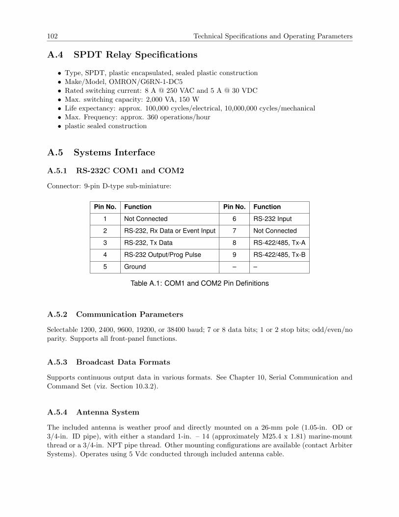
102 Technical Specifications and Operating Parameters
A.4 SPDT Relay Specifications
• Type, SPDT, plastic encapsulated, sealed plastic construction• Make/Model, OMRON/G6RN-1-DC5• Rated switching current: 8 A @ 250 VAC and 5 A @ 30 VDC• Max. switching capacity: 2,000 VA, 150 W• Life expectancy: approx. 100,000 cycles/electrical, 10,000,000 cycles/mechanical• Max. Frequency: approx. 360 operations/hour• plastic sealed construction
A.5 Systems Interface
A.5.1 RS-232C COM1 and COM2
Connector: 9-pin D-type sub-miniature:
Pin No. Function Pin No. Function
1 Not Connected 6 RS-232 Input
2 RS-232, Rx Data or Event Input 7 Not Connected
3 RS-232, Tx Data 8 RS-422/485, Tx-A
4 RS-232 Output/Prog Pulse 9 RS-422/485, Tx-B
5 Ground – –
Table A.1: COM1 and COM2 Pin Definitions
A.5.2 Communication Parameters
Selectable 1200, 2400, 9600, 19200, or 38400 baud; 7 or 8 data bits; 1 or 2 stop bits; odd/even/noparity. Supports all front-panel functions.
A.5.3 Broadcast Data Formats
Supports continuous output data in various formats. See Chapter 10, Serial Communication andCommand Set (viz. Section 10.3.2).
A.5.4 Antenna System
The included antenna is weather proof and directly mounted on a 26-mm pole (1.05-in. OD or3/4-in. ID pipe), with either a standard 1-in. – 14 (approximately M25.4 x 1.81) marine-mountthread or a 3/4-in. NPT pipe thread. Other mounting configurations are available (contact ArbiterSystems). Operates using 5 Vdc conducted through included antenna cable.

A.6 Physical Specifications 103
A.5.5 Antenna Cable
15-meter (50-foot) cable included with antenna. Other cable styles and lengths available – seeTable 4.2.
A.5.6 Operator Interface
RS-232C Interface or eight, front-panel keys
A.5.7 Setup Functions
See Chapter 7, The Setup Menus, for complete details on setting up the operation of the Model1094B.
A.5.8 Display
2-line by 20-character, backlighted supertwist LCD
A.5.9 Display Functions
• Time: UTC or Local
• Position: Latitude, Longitude and Elevation
• Status: Clock, Receiver, EEPROM, Antenna
• 1-PPS (input) Deviation
• Event Time
• Configuration (four keys: SETUP, UP, DOWN, ENTER)
A.5.10 Annunciators - LEDs
• Operate (green)
• Stabilized (green)
• Unlocked (red)
• Fault (red)
A.6 Physical Specifications
A.6.1 Dimensions
Chassis: 430-mm W x 44-mm H x 280-mm D (16.9-in. x 1.7-in. x 11.0-in.)
Antenna: 77-mm Diameter x 66-mm height (3.05-in. x 2.61-in)
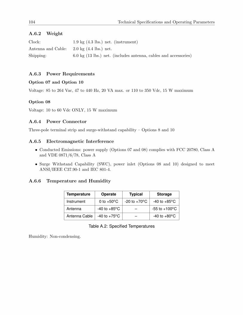
104 Technical Specifications and Operating Parameters
A.6.2 Weight
Clock: 1.9 kg (4.3 lbs.) net. (instrument)
Antenna and Cable: 2.0 kg (4.4 lbs.) net.
Shipping: 6.0 kg (13 lbs.) net. (includes antenna, cables and accessories)
A.6.3 Power Requirements
Option 07 and Option 10
Voltage: 85 to 264 Vac, 47 to 440 Hz, 20 VA max. or 110 to 350 Vdc, 15 W maximum
Option 08
Voltage: 10 to 60 Vdc ONLY, 15 W maximum
A.6.4 Power Connector
Three-pole terminal strip and surge-withstand capability – Options 8 and 10
A.6.5 Electromagnetic Interference
• Conducted Emissions: power supply (Options 07 and 08) complies with FCC 20780, Class Aand VDE 0871/6/78, Class A
• Surge Withstand Capability (SWC), power inlet (Options 08 and 10) designed to meetANSI/IEEE C37.90-1 and IEC 801-4.
A.6.6 Temperature and Humidity
Temperature Operate Typical Storage
Instrument 0 to +50oC -20 to +70oC -40 to +85oC
Antenna -40 to +85oC – -55 to +100oC
Antenna Cable -40 to +75oC – -40 to +80oC
Table A.2: Specified Temperatures
Humidity: Non-condensing.

Appendix B
Using a Surge Arrester
B.1 Introduction
These instructions cover the installation of the Arbiter Systems Model AS0094500, Surge Arrester.The AS0094500 performs two basic functions:
1. Provides a solid and reliable grounding point for the antenna system connected to a GPSreceiver;
2. Protects connected equipment from the damaging effects of atmospheric static electricity andinduced voltage spikes from nearby lightning strikes or other electrical events.
B.2 Description
The AS0094500 is a three-terminal device with two type F connectors and one ground terminal.One of the F connectors connects to the GPS antenna and the other F connector to the GPSreceiver in the clock. A screw terminal provides a point to connect an earth ground wire. Beingweatherproof, the AS0094500 can be mounted outdoors provided that the cabling and Type Fconnectors are sealed from the weather. The device will also pass the DC current necessary toenergize the GPS antenna.
B.3 Installation
B.3.1 Mounting Location
Location is a key consideration when installing the Model AS0094500. Mount as close as possibleto a good earth ground, such as a grounding rod or station ground grid. The shorter the pathbetween the arrester and the earth ground, the more effectively and reliably it will bypass theinduced voltages.
B.3.2 Ground Connection
The Model AS0094500 can be grounded in two ways: (1) via the ground-wire screw connection, or(2) by hard-mounting directly to a grounded metal surface.

106 Using a Surge Arrester
If grounding via the ground-wire screw connection, use the largest possible gauge wire, withthe shortest possible ground path. Hole diameter allows up to 8 AWG wire (0.129 in or 3.26 mm).This wire should be as short as possible, and connected to a good earth ground.
Alternately, the AS0094500 could be mounted directly to a well-grounded plate within thefacility.
B.3.3 Antenna and Clock Connections
The AS0094500 is labeled to indicate which terminals should be connected to the GPS receiver andto the GPS antenna. Use only a low-loss, tri-shield or quad-shield 75-ohm coaxial cable – RG-6or RG-11 are the preferred cable types. RG-59, or other similar types of coaxial cable, should beavoided due to greater signal loss and poorer shielding at the GPS frequency (1.575 GHz).
B.3.4 Weather Sealing the Connections
To protect from weather, use only type F connectors with appropriate sealing features. Typicallythis includes an o-ring in the male connector that seats against the face of the female connector onthe surge arrester. Also, crimped connectors frequently include a silicone gel flooding compound,which enhances the ability of the connection to withstand the rain and humid conditions. To betterseal the entire connection, cover the joint with GE Silicone II compound or a rubber port seal.
Use the proper crimping tool if using crimp-on connectors. Improper tools may not guarantee astrong and sufficiently grounded connector resulting in poor cable performance and GPS reception.Consider purchasing RF cables of various standard and custom lengths manufactured by ArbiterSystems.
B.3.5 Suggested Mounting
Figure B.1 illustrates the recommended mounting of the AS0094500 with the F-connectors facingdownward. Install drip loops in the cables to reduce the likelihood of moisture penetrating thedevice.
B.4 Physical Dimensions
Overall: 59mm x 38mm x 18mm (2.32in x 1.49in x 0.71in) LxWxH
Mounting Hole Dim: 50mm x 15mm
Mounting Hole Dia: 4mm (0.157in)
F Connector Dim: 24mm, center to center
Weight: 48.2 g (1.7 oz)

B.4 Physical Dimensions 107
Figure B.1: Suggested Mounting of the AS0094500 Surge Arrester

Appendix C
Statement of Compliance
C.1 Introduction
The following page is a statement of compliance that includes Model 1094B.

C.1 Introduction 109
G.P.S. Satellite Clock Statement of Compliance
February 5, 2008
TO WHOM IT MAY CONCERN:
All Arbiter Systems, Incorporated G.P.S. Satellite Controlled Clocks are Primary Standards.They provide time traceable to U.T.C. and U.S.N.O. within published accuracy specificationsanywhere in the world. All Arbiter Systems Incorporated G.P.S. Satellite Controlled Clocks alsocarry a limited lifetime warranty, which is based on in field MTBF (Mean Time Between Failures)of over one million (1,000,000) hours. These products are available with all known timesynchronization signals presently in use world wide by the electric power industry.
Arbiter Systems does not supply a type test certificate as requested for G.P.S. systems as theaccuracy is a function of the G.P.S. system and not of the receiver. However we (Arbiter) herebycertify that this equipment conforms to all Arbiter Systems Incorporated specifications formaterial and process. All Arbiter Systems calibration products are supplied with a type testcertificate guaranteeing traceability to National Standards, but are inappropriate for G.P.S.clocks, which are Primary Standards by definition.
Regards,
Bruce H. RoederInternational Marketing ManagerArbiter Systems, Inc.BHR/sc

Appendix D
Switching High Voltage Signals
D.1 Introduction
This section provides information on switching high voltage signal lines (up to 300 Vdc) fromOutputs 1 – 4. Outputs 1 – 4 can be configured as either 5 VCMOS output or a 300-Volt FETpull down. Depending on grounding and isolation requirements, it may be necessary to isolate theconnection between the clock output and the external equipment using a small switching relay.Several examples follow to illustrate logging applications.
D.2 Example 1: 300-Volt FET Pull Down
Figure D.1 illustrates one method of connecting the 300-Volt FET for a pull down event loggingapplication. Use this method with applications when it is acceptable to connect the negative sideof the FET to the 1094B chassis ground. This application could also be used with a periodicprogrammable pulse (e.g. 1 Pulse Per Minute) for timing instead of event logging.
FET Specifications
• VDSS = 400V, max drain-source voltage• RDS(on) = 0.55Ω, max drain-source resistance• Id = 10 A, max continuous drain current (@ 25C)• PD = 3.1 Watts, max power dissipation
Figure D.1: 300-Volt FET with Pull-Down Resistor

D.3 Example 2: 300-Volt FET with Voltage Source in Series 111
D.2.1 Logging Requirements and Circuit Notes
To log an event, the Event Logger must “see” the rising edge of a pulse from 24 to 48 volts. Whenthe pulse clears, or returns to zero, it will be ready to record another event. The connections inFigure D.1 are between the 300-Volt FET and the Event Logger. A 48-volt supply is connectedacross the lines between the clock and the event logger with a 4.7 k ohm resistor in the positivesupply line. This limits the FET current to approximately 10 milliamperes. Configure the Model1094B by setting up for a negative Pulse Polarity so that the FET is turned on and the voltageLogger + side is held low. When the pulse occurs, the FET will turn off and the + line will rise tothe battery voltage and return to zero when the pulse clears.
D.3 Example 2: 300-Volt FET with Voltage Source in Series
Figure D.2 illustrates another method of connecting the 300-Volt FET for a pull down event loggingapplication, however the voltage source is in series with the FET. Such would be the case if the eventlogger had an opto-isolator detector and registered an event with application of current throughthe opto-isolator. This would correspond with the FET in the ‘ON’ state, so pulse configurationwould be “Positive.”
Figure D.2: 300-Volt FET with Voltage Source in Series
D.3.1 Logging Requirements and Circuit Notes
To log an event, the FET must be switched “ON,” which causes a current to flow through the largecircuit, including the Event Logger. The opto-isolator detects the current and the event is recordeduntil the FET switches “OFF,” and the current subsides in the opto-isolator. D1 is an optionalzener diode to protect against voltage spikes smaller than would be protected by the internal diodein the FET. This diode would be chosen specifically from the given application. D2 is a reverseprotection diode (e.g. 1N4001) to protect the opto-isolator. R is a pull-down resistor also scaled tothe application.
D.3.2 Configuring for 300-Volt FET Pull Down
The chosen output needs to be configured for 300V FET using Programmable Pulse A or Pro-grammable Pulse B mode. For jumper selection of the individual outputs, see Table 5.2 and Sec-tion 5.2.1. For Output 1 and 2, use Programmable Pulse A; for Outputs 3 and 4 use ProgrammablePulse B. As an example, for Output 1, set JMP10 to C and JMP11 to A.

112 Switching High Voltage Signals
Configure the programmable pulse through the front panel using the SETUP key or by using1094 Utility application. Both methods allow you full selection of all programmable pulse features.From the front panel, see Section 7.9, and using the 1094 Utility, see Section 6.6.8 or Section 6.6.9.
D.4 Example 3: 5 Volt Switching with External Relay
Figure D.3 illustrates the connection between the the Model 1094B and the logger, with intermediateswitching relay. As mentioned in the introduction, some applications may require a positive ground,or method to isolate the recorder or event logger from the Model 1094B. To accomplish this, it issimple to place a small switching relay between the clock output and the event logger. Since theapplication requires a positive ground, the small relay isolates the clock from the event logger.
Figure D.3: 5 Volt Switching with Isolation Relay
D.4.1 Configuring for 5-Volt CMOS
The chosen output needs to be configured for 5V CMOS and Programmable Pulse. Therefore, forOutput 1, set JMP10 to C and JMP11 to C. Outputs 2, 3 and 4 would be set similarly.

Index
1-PPSdescription, 67
1094B softwareconnecting, 34display setup, 44opening configuration file, 45prog pulse A, 42prog pulse B, 43reading clock config, 36saving configuration file, 45serial parameters, 39system parameters, 37time adjustment, 40, 41upload warning, 45uploading new firmware, 45USB-to-Serial adapters, 35
300-Volt FET, 110protection, 68setup, 68
accessoriesincluded, 1
accessory cables, 20altitude, see elevation displayanalog drivers, 65antenna
checking resistance, 18clock connection, 21connection, 15, 21installation, 15mounting assembly, 16mounting kit, 15, 16mounting procedure, 16power supplied to, 21user-supplied cables, 21voltage, 18voltage check, 18
antenna & cable testing, 18antenna cable, 19
antenna cableeffects of cable parameters, 19
AppendixA, 100D, 108E, 110
cableaccessory, 20adjacent signal interference, 21attenuation, 20DC resistance, 20delay, 19delays, 71distance, 69physical protection, 20timing output, 69user-supplied, 21wire losses, 71
caution, see precautionsCOM Port
identifying, 35reassigning number, 35
comm ports, 79command key
definitions, 6configure
Backlight, 53begin, 48Cable Delay, 54com ports, 49Daylight Saving, 52Event Inputs, 63firmware setup, 47IRIG-B, 61Local Offset, 51Out of Lock, 53programmable pulse, 55Summertime, 52

114 INDEX
Survey Mode, 62
configure clock
COM parameters, 39
connect, 34
display, 44
IRIG-B, 41
open new configuration, 45
prog pulse A, 42
prog pulse B, 43
read configuration, 36
save config file, 45
system, 37
time adjustment, 40
tutorial, 33
usb-to-serial adapter, 35
Windows device manager, 35
configuring
Jumpers
output, 23
connecting
modulated IRIG-B, 70
outputs, 69
relay contacts, 74
unmodulated IRIG-B, 70
connecting power to the clock, see inlet power
connector
antenna, 8, 15
event input, 9
power inlet, 7
relay contacts, 9
serial communications, 9
timing output, 10
Contact Information, ii
copyright, v
cordsets
IED-320 power inlet connector, 12
custom broadcast
return string, 82
string command, 81
string setup, 80
Daylight Saving Time, 40
defaults
resetting to, 44
deviation
measurement, 75
measurement principle, 75digital drivers, 65display
startup, 28display modes
Position, 32Time, 30
drive current vs. output voltage, 65driver
analog, 65digital, 65
elevation display, 32event channel
programming, 26setup, 26
event display indication, 29event inputs, 74
allowable input voltage, 26channel configuration, 75clearing all events, 77displaying data, 76event format, 76introduction, 74number of records, 76timing principle, 74
eventsclear event buffer, 38
factory defaultsresetting to, 44
faultconditions, 73viewing, 73
fault indication, 5fault modes, 30Firmware updates, iifront panel drawing, see panel drawing, frontfuses
replacing, 14types and location, 13
gpssurge arrester, 18, 105
handlingprecautions, 1

INDEX 115
humidity, 104
IEC-320 power inlet connector, 7
initial clock time, 27
initial LED indication, 27
initial startup sequence, 27
inlet power, 11
IRIG-B
IEEE 1344 description, 67
initial indication, 30
modulated
voltage matching, 71
timecode description, 66
waveform comparison, 67
IRIG-B Time code types, 66
jumpers
configuring
communication, 25
event input, 26
output, 23
relay contacts, 24
mainboard, list of functions, 23
keys
description, 6
Down, 7
Enter, 7
Event/Deviation, 6
Position, 6
Setup, 6
Status, 6
Time, 6
Up, 7
latitude display, 32
LCD
display, 5
LED
annunciator
definitions, 5
longitude display, 32
mounting kit
antenna, 15
numeric data entry mode, 48, 54
open drain, see 300-Volt FETOption
08, terminals with SWC, 810, terminals with SWC, 8
Options07, IEC-320 connector, 7power, 07, 11power, 08, 12power, 10, 13
output signaldescription, 66
panelrear
description, 64panels
drawingfront, 4rear, 7
front, 4rear, 4
position display modes, 32datum, 32
precautions, 1programmable pulse, see configure
Aux IRIG Mode, 60description, 68Frequency Mode, 60preliminary setup values, 56pulse width, 68Pulse-Per-Day Mode, 58Pulse-Per-Hour Mode, 57Pulse-Per-Minute Mode, 57Pulse-Per-Second Mode, 56Seconds-Per-Pulse Mode, 59Single Trigger Mode, 58Slow Code Mode, 59
rack mountears, 2mounting instructions, 2
rear panel, see panel, rearrelay contacts
connecting, 74connector, 9functions, 73modes, 24

116 INDEX
specifications, 25, 102
ROM date, ii
RS-232C Communication, see serial command
serial command
antenna delay
set, 98
broadcast
interrogate, 84
ABB, 87
ASCII + Quality, 86
ASCII Std, 84
custom, 81
Display Screen, 88
Event Data, 84
Extended ASCII, 85
Kissimmee, 88
NGTS, 89
NMEA183 GLL, 86
NMEA183 ZDA, 87
Philippe, 88
Status, 85
Vorne Std, 84
Year + ASCII, 86
broadcast strings, 83
DST/Summertime
activate, 92
return settings, 92
start time, 93
stop time, 93
Event
channel time, 90
control operation, 90
return deviation, 90
Event number, 90
front panel backlight control, 93
Local Offset, 93
out-of-lock alarm
set time, 98
Prog Pulse
pulse delay, 97
pulse frequency, 98
pulse polarity, 97, 98
set mode, 96
set pulse width, 96
set time mark, 97
return
display buffer, 99
firmware version, 98
local date, 95
local time, 96
UTC date, 96
UTC time, 96
return elevation, 94
return longitude, 95
set
com settings, 83
display mode, 99
receiver position, 95
set IEEE 1344 mode, 94
set receiver time, 95
Status
clock, 91
EEPROM, 91
receiver, 91
status of event/deviation, 91
time quality, 92
survey mode, 99
serial port
output symbols, 80
pin definitions, 79, 102
Setup menu list, 47
signal
output
description, 66
software
see1094B software, 33
specifications, 100
accuracy, 100
acquisition, 101
annunciator LED’s, 103
antenna cable, 103
antenna system, 102
dimensions, 103
display, 103
display functions, 103
electromagnetic interference, 104
event timing, 101
GPS receiver, 100
I/O connectors, 101
input functions, 101
operator interface, 103

INDEX 117
oscillator, 100position accuracy, 100power connector, 104power requirements, 104satellite tracking, 100serial port parameters, 102serial port pinout, 102serial ports, 102setup functions, 103standard output signals, 101temperature and humidity, 104timing outputs, 101weight, 104
startup sequence, 27Statement of Compliance, 108status display indication, 29surge arrester, 18, 105synchronizing
multiple devices on one port, 69
temperatures, 104time display modes, 30timing outputs
description, 64intro, 64
title page, v
unpacking the clock, 1
warranty, iiiWGS-84, 32