model 1020 serial no. - babe ruth...
TRANSCRIPT

Nevco Scoreboard CompanyInstallation and Service Manual
Model 1020 Serial No. ________________
Since 1934
Retain this manual in your permanent files
6-29-98 5232-CM
. .

Installation and Service Manual MODEL 1020
Ta ble of Con tentsIn stal la tion In struc tions . . . . . . . . . . . . . . . . . . . . . . . . . . . . . . . . . . . . . . . . . . . 2Pre-mounting Test . . . . . . . . . . . . . . . . . . . . . . . . . . . . . . . . . . . . . . . . . . . . . . 2Two Digit Clock . . . . . . . . . . . . . . . . . . . . . . . . . . . . . . . . . . . . . . . . . . . . . . . 2Score board Mount ing . . . . . . . . . . . . . . . . . . . . . . . . . . . . . . . . . . . . . . . . . . . . 3Score board Power Ser vice Con nec tion . . . . . . . . . . . . . . . . . . . . . . . . . . . . . . . . . . 3Score board Sys tem . . . . . . . . . . . . . . . . . . . . . . . . . . . . . . . . . . . . . . . . . . . . . 4As sem bly Method for 2-WIRE Twist On Con nec tor Part Num ber 210-0008 . . . . . . . . . . . . . . . . 4Pre cau tions . . . . . . . . . . . . . . . . . . . . . . . . . . . . . . . . . . . . . . . . . . . . . . . . . 5MPC Power Ser vice Con nec tion . . . . . . . . . . . . . . . . . . . . . . . . . . . . . . . . . . . . . . 5Re place able Parts List. . . . . . . . . . . . . . . . . . . . . . . . . . . . . . . . . . . . . . . . . . . . 5Out door In stal la tion 1020 . . . . . . . . . . . . . . . . . . . . . . . . . . . . . . . . . . . . . . D4624-1Out door In stal la tion 1020 . . . . . . . . . . . . . . . . . . . . . . . . . . . . . . . . . . . . . . D4624-2Base ball Sin gle Score board Sys tem . . . . . . . . . . . . . . . . . . . . . . . . . . . . . . . . . C5901Base ball Sin gle Score board W/Al ter nate Con trol Point Sys tem. . . . . . . . . . . . . . . . . . . C5935Mod ule End View M7-9 . . . . . . . . . . . . . . . . . . . . . . . . . . . . . . . . . . . . . . . . B4626Testing the MPC-4 Con trol . . . . . . . . . . . . . . . . . . . . . . . . . . . . . . . . . . . . . . . . . 112-EM-2 or 2-EM-3 Mod ule / Op er a tion, Testing . . . . . . . . . . . . . . . . . . . . . . . . . . . . . . 11Trou ble Shoot ing Guide . . . . . . . . . . . . . . . . . . . . . . . . . . . . . . . . . . . . . . . . . . 12Nevco State ment . . . . . . . . . . . . . . . . . . . . . . . . . . . . . . . . . . . . . . . . . . . . . . 14Fed eral Com mu ni ca tions Com mis sion Re quired State ment . . . . . . . . . . . . . . . . . . . . . . . 14Ca na dian De part ment of Com mu ni ca tions ( D.O.C.) State ment . . . . . . . . . . . . . . . . . . . . . 14Five (5) Year Guar an tee . . . . . . . . . . . . . . . . . . . . . . . . . . . . . . . . . . . . . . . . . . 14Re quest for Ser vice or Parts . . . . . . . . . . . . . . . . . . . . . . . . . . . . . . . . . . . . . . . . 15
Introduction To Nevco ScoreboardsWe at Nevco Scoreboard Company would like to introduce you to our latest Solid State Scoreboard. The universal
MPC Microprocessor Control operates more than 500 Nevco scoreboard variations and is the heart of Nevco’sreliability. Scoring from sport to sport is as easy as popping on a new keyboard overlay. Now, you can read and recallthe inning, scores and all other game information on the control’s bright display. Each control comes with keyboardoverlay, operating instructions, TCS-1 time switch and 25 feet of control cable. An optional CC-2 carrying case isavailable at extra charge.
The model 1020 is small, yet the most economically priced baseball, softball and soccer scoreboard for any sizefacility. The model 1020 has the new 2 digit style clock which is also used to display the inning. Other features includeteam scores registering from 0-99 to cover the full range of scoring by different age groups, and single lampindicators for the balls, strikes and outs. Numerals are 18" high with individual aluminum reflectors for each lamp toprovide maximum figure clarity. Locate the scoreboard on the south or west side of the field (USA) for proper daytimevisibility. Scoreboard cabinet is aluminum. Mounting brackets are supplied for mounting on your posts. Scoreboardis fully solid state and operates on a simple 2-WIRE cable. Scoreboard uses the MPC microprocessor basedoperator’s control which has scoreboard lamp dimming capability.
Size: 10’ x 4’ x 8" (3.04 x 1.21 x .20 meters). Approx. hanging weight 160 lbs. (72 kg.).The data from the operator’s MPC control is transmitted to the scoreboard through a low voltage (class 2) coaxial,
2-WIRE control cable. All the scoreboard electronics are housed in one module located behind the rear service door.This module continuously receives, translates and displays the information sent from the operator’s MPC control.The module switches all the power to the lamp displays to light the numbers and indicators on the scoreboard face.
In the following pages you will learn about the equipment you have received, pre-testing the equipment beforeinstallation, mounting procedure and connecting power to your equipment, with illustrations to assist you. Alsoincluded in the manual are installation precautions, a complete list of replaceable parts, a trouble shooting guide andNevco’s FIVE Year Guarantee.
Please read this manual completely and carefully before attempting any of the installation procedures. Always keep this manual in a safe place for future reference.
6-29-98 5232-CM

MODEL 1020 Installation and Service Manual
6-29-98 5232-CM Page 2
Installation Instructions
The sys tem in cludes an op er a tor’s MPC con trol (ifor dered), the score board cab i net, “S” brack ets, con -trol junc tion box with cover and ca bles. To in sure thatyour new score board sys tem has ar rived safely, it isim por tant to fol low the steps be low:
Step 1 Carefully remove the scoreboard fromthe crate making sure not to pry againstthe scoreboard in any way, and inspectfor damage. Model 1020 comes in onesection.
Step 2 Carefully remove the operator’s MPCcontrol from its packing carton and check for damage. Contact the carr ierimmediately if shipping damage ispresent either to the scoreboard or thecontrol.
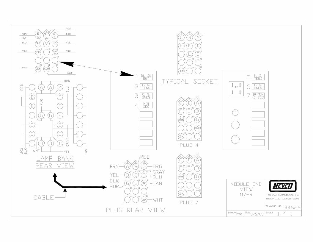
Step 3 Open the door labeled module locationon print number D4624-1 and check theelectronic module for loose connectors.To open the module location, use astandard screw driver to turn the latches.Should some cables come loose ordisconnected refer to drawing B4626.This print is a module end view, whichshows you where to plug the loose ordisconnected cable(s) and the functionof each module plug.
Step 4
Pre-mounting Test
Con nect the 25 foot 2-WIRE con trol ca ble, which co -mes pack aged in the con trol car ton, from the op er a -tor’s MPC con trol to the mod ule.
Step 5 Connect the scoreboard to a temporarypower service. See installation printD4624-2 for power requirements andwiring color code.
Step 6 Plug the MPC control power cord into any 120V, 60HZ grounded three wire outlet.Only 0.1A required.
Step 7 Follow the operat ing instruct ionssupplied with the MPC operator’s controlto make sure the system operatesproperly before going on with theinstallation. Be sure to read the sectiontitled Two Digit Clock before operation.
Step 8 If the scoreboard does not operateproperly, refer to the section titledTesting the MPC-4 Control and thesection titled 2-EM-2 or 2-EM-3 Module / Operation, Testing before referring tothe Trouble Shooting Guide.
Two Digit Clock
The new style clock dis plays both min utes and sec -onds us ing only 2 dig its and 2 sets of co lons.
When the time is running only the minutes aredisplayed with the colon on the right side being lit. The top light of the right colon blinks every second whenmore than 30 seconds are left in each minute. Whenless than 30 seconds, the bottom light of the rightcolon blinks.
Once the time remaining is less than one minute theright colon goes blank and the left colon lights, theseconds are now displayed.
When the time expires the time display goescompletely blank.
If the time is stopped the display alternates betweenthe minutes and seconds letting you see the exacttime remaining on the clock.
Also note that the time display may also be used asan inning indicator.

Installation and Service Manual MODEL 1020
Page 3 6-29-98 5232-CM
Step 9
Scoreboard Mounting
Draw ing num ber D4624-1 and D4624-2 shows themount ing meth ods, mount ing cen ters, power ser vicelo ca tion and the con trol ca ble in puts. Be fore mount -ing the sup plied “S” brack ets to the beam, mea sure
Step 10
Scoreboard Power Service Connection
The re quired power ser vice for this score board is120V, 20A, 60HZ. This al lows a 20 per cent safety fac -tor to elim i nate nui sance trip ping of the power ser vicecir cuit breaker. To elim i nate ser vice prob lems at somefu ture date and the pos si bil ity of over load ing the cir -cuit breaker, we sug gest in stall ing a ded i cated ser vice or cir cuit for the score board.
the slot lo ca tions on the score board. Man u fac turingtol er ances, tem per a tures and other vari ables may af -fect the ac tual slot lo ca tion. With the front edge point -ing up, mount the bot tom “S” bracket to the beam with two 5/8" bolts. Af ter the bot tom “S” brack ets are se -cured, po si tion the score board with the holes in thefront edge of the “S” brack ets aligned with the 1 1/2" x11/16" slots on the face of the score board. Now, in stall the top “S” brack ets se curely against the top of thescore board, align ing the “S” bracket holes with thescore board slots. Once all “S” brack ets are in place,in sert the 5/8" bolt through the front of the “S” brack -ets, score board and wide flange beam se cur ing it with a flat washer and lock ing nut. Do not over tighten thisbolt. A self lock ing nut must be used to pre vent loos -en ing.
No tice, the mod ule lo ca tion is on the rear of thescore board. You must keep a three foot clear ancebe hind the score board to al low the mod ule lo ca -tion door to open freely.
Al ways use good me chan i cal prac tices whenmount ing the score board mak ing sure the bolt orother type fas ten ing de vice used has a flat washer,lock washer and or lock nut where spec i fied to pre vent vi bra tion from loos en ing the fas ten ing de vice. Useonly plated fas ten ing de vices to pre vent rust or cor ro -sion. The dis tance be tween the mount ing posts mustmain tain a tol er ance of plus or mi nus 1/2".
The 6 x 6 x 15 lbs wide flange beam is for a nom i nal75 m.p.h. wind load ing, which may not be ad e quatefor some lo cales. We strongly en cour age you tocheck lo cal codes be fore start ing the in stal la tion. Ifyou are un sure of how to go about this, con tact a lo calar chi tect, con trac tor, or sign in staller for as sis tance.Your Nevco Sales Rep re sen ta tive may also be able toas sist you in find ing pro fes sional in stal la tion com pa -nies who are fa mil iar with this type of equip ment.
NOTE:USE ONLY UL LISTED, CSA CER TIFIED 20 AMPGROUND FAULT IN TER RUPTERS.
The con trac tor or in stal la tion per son nel will de ter -mine length and size of the wire to main tain the volt -age needed to sup port the cir cuit load. Werec om mend the power ser vice main tain 120V at thescore board un der max i mum lamp load.
NOTE:SAFETY GROUND (GREEN WIRE) MUST BE THESAME GAUGE AS POWER SER VICE ORGREATER.
The con trac tor or in stal la tion per son nel may burythe power ser vice wire(s) and con trol ca ble in thesame trench or non-conductive con duit. Con sult theNa tional Elec tri cal Code and lo cal codes be fore in -stall ing. Also see Step 11 on 2-WIRE ca ble in stal la tionfor de tail.
Make the fi nal power ser vice con nec tion in the re -cessed en trance box lo cated on the back of score -board. See draw ing D4624-2 for de tail and wir ingcolor code.

MODEL 1020 Installation and Service Manual
6-29-98 5232-CM Page 4
Step 11
Scoreboard Systems
The 2-WIRE ca ble, if or dered from Nevco Score -board Com pany, is spe cif i cally de signed for un der -ground burial with a di elec tric strength of 300 volts orbetter and con forms to UL stan dard 1365.
Con sult the Na tional Elec tri cal Code and lo cal codes for in stal la tion of Class 2 wir ing. If bur ied above thefreeze line, bury the ca ble with sand to pro vide drain -age and pre vent soil shift ing from dam ag ing the ca -ble.
Draw ing C5901 il lus trates the 2-WIRE ca ble con nec -tion to the 4" x 2 1/8" x 2 1/8" dry lo ca tion junc tion box.
For proper safety and pro tec tion of the score boardelec tron ics from light ning and other elec tri cal prob -lems, at tach the green ground wire to a sep a rateground stake at the score board. See de tail on draw -ing D4624-2 for ground stake in stal la tion.
You must in stall a UL Listed, CSA Cer tified power dis -con nect switch at the score board.
Turn the dis con nect off be fore you at tempt any ser -vice to the score board. You must also turn the dis con -nect off when the score board is not in use to pro tectyour score board from light ning dam age. Just as a re -minder, your score board guar an tee does not coverlight ning dam age or other types of dam age caused by nat u ral di sas ters.
Slide in su lat ing booton the ca ble and trim ca -ble as shown.
Twist the outer braid ina clock wise di rec tion soat least 1/32" of the in nerdi elec tric is bared andthe braid is left flat.
In sert the cen ter con -duc tor into the back ofthe con nec tor, feel ing itinto the guide hole.
Push the ca ble as faras pos si ble into con nec -tor, next screw the con -nec tor on to the ca ble ina clock wise di rec tionun til it stops. Then slipthe in su lat ing boot overthe back of the con nec -tor.
Step 12
Assembly Method for 2-WIRE Twist On ConnectorPart Number 210-0008
• NOTE: 2-WIRE ca ble from the Nevco fac toryco mes with out con nec tors at tached.
If the junc tion box is not in a dry lo ca tion, re fer todraw ing C5935 for pro tect ing the junc tion box fromout door weather con di tions.
Please note you must ground this junc tion box re -gard less of the lo ca tion. Use only an iso lated groundstake. Do not use the ground stake for any other ap pli -ances.
Con tact the Nevco fac tory for sys tem in stal la tionsnot cov ered in this man ual.
Installation and Service Manual MODEL 1020
Page 5 6-29-98 5232-CM
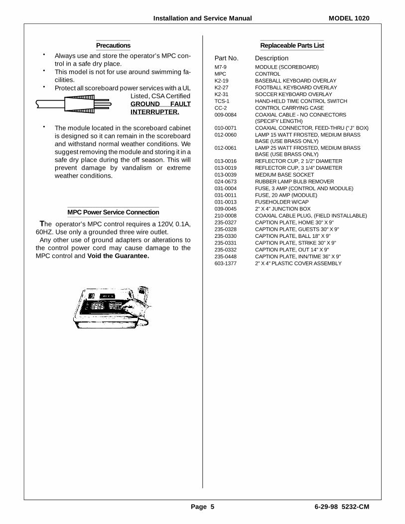
Replaceable Parts List
Part No. DescriptionM7-9 MODULE (SCOREBOARD)MPC CONTROLK2-19 BASEBALL KEYBOARD OVERLAY K2-27 FOOTBALL KEYBOARD OVERLAYK2-31 SOCCER KEYBOARD OVERLAYTCS-1 HAND-HELD TIME CONTROL SWITCHCC-2 CONTROL CARRYING CASE009-0084 COAXIAL CABLE - NO CONNECTORS
(SPECIFY LENGTH)010-0071 COAXIAL CONNECTOR, FEED-THRU (“J” BOX)012-0060 LAMP 15 WATT FROSTED, MEDIUM BRASS
BASE (USE BRASS ONLY)012-0061 LAMP 25 WATT FROSTED, MEDIUM BRASS
BASE (USE BRASS ONLY)013-0016 REFLECTOR CUP, 2 1/2" DIAMETER013-0019 REFLECTOR CUP, 3 1/4" DIAMETER013-0039 MEDIUM BASE SOCKET024-0673 RUBBER LAMP BULB REMOVER031-0004 FUSE, 3 AMP (CONTROL AND MODULE)031-0011 FUSE, 20 AMP (MODULE)031-0013 FUSEHOLDER W/CAP039-0045 2" X 4" JUNCTION BOX210-0008 COAXIAL CABLE PLUG, (FIELD INSTALLABLE)235-0327 CAPTION PLATE, HOME 30" X 9"235-0328 CAPTION PLATE, GUESTS 30" X 9"235-0330 CAPTION PLATE, BALL 18" X 9"235-0331 CAPTION PLATE, STRIKE 30" X 9"235-0332 CAPTION PLATE, OUT 14" X 9"235-0448 CAPTION PLATE, INN/TIME 36" X 9"603-1377 2" X 4" PLASTIC COVER ASSEMBLY
Precautions• Al ways use and store the op er a tor’s MPC con -
trol in a safe dry place.• This model is not for use around swim ming fa -
cil i ties.• Pro tect all score board power ser vices with a UL
Listed, CSA Cer tified GROUND FAULTIN TER RUPTER.
• The mod ule lo cated in the score board cab i netis de signed so it can re main in the score boardand with stand nor mal weather con di tions. Wesug gest re mov ing the mod ule and stor ing it in a safe dry place dur ing the off sea son. This willpre vent dam age by van dal ism or ex tremeweather con di tions.
MPC Power Service Connection
The op er a tor’s MPC con trol re quires a 120V, 0.1A,60HZ. Use only a grounded three wire out let.
Any other use of ground adapt ers or al ter ations tothe con trol power cord may cause dam age to theMPC con trol and Void the Guar an tee.

HW 1 2
INSTALLATION1020
3/3/89
D4624
3 3/8"
2"
10 1/4"MINIMUM
1 1/2"
5/8" BOLTTYP. *
BEAM SCOREBOARD
FLAT WASHER *
LOCK NUT *
5/8" BOLT *
FLAT WASHER *
FILL REMAINING SPACEWITH 5/8" FLAT WASHERS
1 1/2" X 11/16" SLOT IN FACEAND BACK OF SCOREBOARD (TYP.)
SCOREBOARDFACE
REVG
"S" Bracket **
"S" Bracket Detail
DATEDRAWN
NEVCO SCOREBOARD CO.
GREENVILLE, ILLINOIS 62246
OFSHEET
DRAWING NO.
Certified ground fault breaker. The above should be installed per the National ElectricalUL Listed, CSA Certified ground fault or an outlet that is connected to a UL Listed, CSAThe outlet for the control is to be supplied by the owner. The outlet should be either aItems supplied by NevcoItems supplied by owner
Code.
** 1.
NOTES:*
Scoreboard Company does not accept responsibility for scoreboards damaged by natural or other causes.Regardless of the procedures, beams, posts, brackets, screws or hardware used for the installation, Nevco
The mechanical installation described on this drawing is a guide to the elementary concepts involved withREAD THIS BEFORE INSTALLATION
drawing, careful analysis of the installation is urged.If procedures are used or additional equipment added - such as signs - that are not covered by thisstress analysis are available upon request.Nevco are adequate for your local soil, wind, codes and other conditions. Calculations for "S" bracketmounting beams or posts along with the brackets, screws and other hardware items provided by you orprofessional engineer or architect before attempting the installation. They can verify that the selectedthe installation. This is not intended to be suitable for all conditions. We recommend consulting a
Refer to the Nevco guarantee.
MPC-4
5 1/4"
10'-0" MinimumClearance
5'-0" Minimum
2'-0"Minimum
8'-6"Top View
Rear View
ModuleLocation
Approximateweight 160 lbs 6 x 6 x 15 lbs minimum
wide flanged steel support *
Raintight power disconnect *
Raintight circuit box *
To control center
Conduit as required *
Ground level
Minimum2'-0"
Side View
Mounting "S" brackets ** 4 required
Coarse aggregate concrete *Minimum 3/4 yds of concrete per hole
4'-0"
9"

PEF 2 2
INSTALLATION1020
1/2/94
D4624
Green wire - Earth Ground
Black wire - M7-9 LoadCOLOR CODE
White wire - M7-9 Load Neutral
M7-9
Power splicebox
1/2" conduit for coax *
Conduit asrequired *
UL Listed, CSA Certifiedground fault interrupter 20 amp *
Raintight circuit box *
Raintight non-fused power disconnectbox * (box must be turned off whenscoreboard is not in use)
Box must be in sight & lockable
Ground stakes: check NationalElectrical Code & local codes forlength & installation specificications *
Power lines
These stakes must notbe used for otherappliances.
12 ga. insulated wire
Power Cord120V, 0.1A, 60HZ
25'-0"
10'-0"
Dry location junction box 4" x 2 1/8" x 2 1/8" and cover. **Box must not be in contact with metal structures such aspress box or bleachers.
Make connection to eithercontrol cable jack.
1/4" dia. direct burial 2-WIREcoaxial control cable RG58/Uorder lenght required from Nevco Press Box (Dry Location)
Up to 100 feet run 12 ga. wire100 to 200 feet run 10 ga. wire200 to 300 feet run 8 ga. wire300 to 600 feet run 6 ga. wire600 to 900 feet run 4 ga. wireSafety ground (grn wire) must besame gauge as power service orgreater. Check local codes forminimum wire size required.
Control
DATEDRAWN
NEVCO SCOREBOARD CO.
GREENVILLE, ILLINOIS 62246
OFSHEET
DRAWING NO.
The standard system includes an operator's MPCcontrol (if ordered), the scoreboard cabinet, "S"brackets, control junction box with cover andcables. To insure that your new scoreboardsystem has arrived safely, it is important to followthe steps below:
Step 1Carefully remove the scoreboard from the cratemaking sure not to pry against the scoreboardin any way, and inspect for damage. Thismodel comes in one section.
Step 2Carefully remove the operator's MPC controlfrom its packing carton and check for damage.Contact the carrier immediately if shippingdamage is present either to the scoreboard orthe control.
Step 3Open the door labeled module location andcheck the electronic module for looseconnectors. To open the module location, use astandard screw driver to turn the latches.Should some cables come loose ordisconnected refer to the module end view printB4626 for plug information.
Step 4
Connect the 25 foot 2-WIRE control cable,which comes packaged in the control carton,from the operator's MPC control to themodules.
Step 5Connect the scoreboard to a temporary powerservice. See this page for power requirementsand wiring color code.
Step 6Plug the MPC control power cord into any120V, 60HZ grounded three wire outlet. Only0.1A required.
Step 7Follow the operating instructions supplied withthe MPC operator's control to make sure thesystem operates properly before going on withthe installation.
Step 8If the scoreboard does not operate properly,refer to the Installation and Service Manual,
Step 9
A typical "S" bracket mounting detail is shownon page 1. Before mounting the supplied "S"brackets to the beam, measure the slotlocations on the scoreboard. Manufacturingtolerances, temperatures and other variablesmay affect the actual slot location. With thefront edge pointing up, mount the bottom "S" tothe beam with two 5/8" bolts. After the bottom"S" brackets are secured, position thescoreboard with the holes in the front edge ofthe "S" brackets aligned with the 1 1/2" x 11/16"slots on the face of the scoreboard. Now, installthe top "S" brackets securely against the top ofthe scoreboard, aligning the "S" bracket holeswith the scoreboard slots. Once all "S" bracketsare in place, insert the 5/8" bolt through thefront of the "S" brackets, scoreboard and wideflange beam securing it with a flat washer andlocking nut. Do not overtighten this bolt. A selflocking nut must be used to prevent loosening.Notice, the module location is on the rear of thescoreboard.
Always use good mechanical practices whenmounting the scoreboard making sure the boltor other type fastening device used has a flatwasher, lock washer and or lock nut wherespecified to prevent vibration from loosening
the fastening device. Use only plated fasteningdevices to prevent rust or corrosion. Thedistance between the mounting posts mustmaintain a tolerance of plus or minus 1/2".The 6 x 6 x 15 lbs wide flange beam is for anominal 75 m.p.h. wind loading, which may notbe adequate for some locales. We stronglyencourage you to check local codes beforestarting the installation. If you are unsure ofhow to go about this, contact a local architect,contractor, or sign installer for assistance. YourNevco Sales Representative may also be ableto assist you in finding professional installationcompanies who are familiar with this type ofequipment.
Step 10
The required power service for this scoreboardis 120V, 20A, 60HZ. This allows a 20 per centsafety factor to eliminate nuisance tripping ofthe power service circuit breaker. To eliminateservice problems at some future date and thepossibility of overloading the circuit breaker, wesuggest installing a dedicated service or circuitfor the scoreboard.
Use only UL Listed, CSA Certified 20amp ground fault interrupters.The contractor or installation personnel willdetermine length and size of the wire tomaintain the voltage needed to support thecircuit load. We recommend the power servicemaintain 120V at the scoreboard undermaximum lamp load.The contractor or installation personnel maybury the power service wire(s) and controlcable in the same trench or non-conductiveconduit.
The 2-WIRE cable, if ordered from NevcoScoreboard Company, is specifically designedfor underground burial with a dielectric strengthof 300 volts or better and conforms to ULstandard 1365. Consult the National ElectricalCode and local codes before installing.Consult the National Electrical Code and localcodes for installation of Class 2 wiring. If buriedabove the freeze line, bury the cable with sandto provide drainage and prevent soil shiftingfrom damaging the cable.Make the final power service connection in therecessed entrance box located on the back ofscoreboard. See Power Splice Box on thispage for detail and wiring color code.For proper safety and protection of thescoreboard electronics from lightning and otherelectrical problems, attach the green groundwire to a separate ground stake at thescoreboard. See detail on this page for groundstake installation.You must install a UL Listed, CSA Certifiedpower disconnect switch at the scoreboard.Turn the disconnect off before you attempt anyservice to the scoreboard. You must also turnthe disconnect off when the scoreboard is notin use to protect your scoreboard from lightningdamage. Just as a reminder, your scoreboardguarantee does not cover lightning damage orother types of damage caused by naturaldisasters.
Installation Instructions
Pre-mounting Test
Scoreboard Mounting
You must keep a three footclearance behind the scoreboard toallow the module location door to open
NOTE:
Scoreboard Power Service
sections titled Testing the MPC-4 Controland 2-EM-2 or 2-EM-3 Module/OperationTesting, before referring to the TroubleShooting Guide.
freely.
REV
B
MPC-4


Installation and Service Manual MODEL 1020
Page 11 6-29-98 5232-CM
Testing the MPC-4 Control
Dis con nect the score board con trol ca ble from thecon trol. Turn on the con trol. If the run ning dis playdoes not ap pear, the con trol is mal func tion ing.
The run ning dis play uses all seg ments (light bars) inthe dis play. If any seg ment does not light, make care -ful note of its lo ca tion.
Now dis con nect any re mote hand-held switchesfrom the con trol. En ter the fol low ing model code:
• Press . . . 4 3 2 1 0 8 8The dis play will now show:
MPC4 OK 0 The MPC4 OK in the dis play shows the test of the in -
ter nal mem ory passed. If the test fails, make note ofwhat the dis play reads and con tact Nevco Ser vice De -part ment for help.
To test the (ALT TIME SWITCH), all hand-heldswitches must be dis con nected. Pressing the switchto the ON po si tion will make the dis play show:
MPC4 O K A1 Pressing the switch to the OFF po si tion will make the
dis play show:
MPC4 O K A2 If ei ther the TCS-1 or GJS-1 re mote hand-held
switches are plugged in to ei ther side of the con trolthey will dis able the (ALT TIME SWITCH).
Plug the re mote hand-held time switch TCS-1 intoone of the sock ets on ei ther side of the con trol. Withthis switch in time ON, the num ber at the far right of the dis play should be a 1. EX AM PLE:
MPC4 O K 1 With the switch in the time OFF po si tion the num ber
should be a 2. Now, plug the hand-held switch into theother side of the con trol. You should get the same re -sult. A bro ken wire in the hand-held switch may causein ter mit tent prob lems. Wig gle the ca ble of thehand-held switch. If the num ber changes while do ingthis, there is a bro ken wire. Try this in both switch po si -tions.
All hand-held switches are tested the same way. Thefol low ing is a list of Nevco hand-held switches and thecor rect test re sults.
TYPE SWITCH DISPLAYTCS-1 ON 1
OFF 2SCS-1 TIME 4
10 SEC. 8SCS-2 TIME 4
O.B.RESET 8SCS-3 RESET 4
TIME 8SCS-4 O.B. 8
S.T. 4HOLD <
DGS-1 TIME 8RESET 4
GJS-1 ON 1OFF 2
To test the key board, just press one of the but tons.The dis play will show a num ber cor re spond ing to thebut ton pressed.
EX AM PLE:
MPC4 O K 14 1 A chart of the but ton po si tion num bers fol lows:
41 42 43 44 45 46 47 4831 32 33 34 35 36 37 3821 22 23 24 25 26 27 28
11 12 13 14 15 16 17 18That com pletes the self test. If any of the tests fail,
make care ful note of the mal func tion to in clude withthe con trol when re turned to Nevco Score board Com -pany.
2-EM-2 or 2-EM-3 Module / Operation, Testing
Operation
The 2-EM-2 or 2-EM-3 score board lamp drive mod -ule lo cated in side the score board re places the pre vi -ously man u fac tured 2-EM and 2-EM-1 mod ules. The2-EM-2 or 2-EM-3 mod ules are phys i cally iden ti cal totheir pre de ces sors. Score boards orig i nally equippedwith 2-EM or 2-EM-1 mod ules may use the new2-EM-2 or 2-EM-3 mod ules.
A mi cro com puter di rects the func tions of the 2-EM-2or 2-EM-3 mod ule mak ing the score board a “smart”sys tem. Al though the nor mal func tion of the score -board does not change, hid den “in tel li gence” is atwork to im prove the re li abil ity of the sys tem. Powermon i tor ing within the mod ule can pre vent dam age tothe score board face from harm ing the mod ule and
MODEL 1020 Installation and Service Manual
6-29-98 5232-CM Page 12
Trouble Shooting Guide
Usually a score board mal func tion is a com po nentfail ure or bad me chan i cal con nec tion. The trou bleshoot ing guide is a method of lo cat ing the fail ure. Theowner can then make the in for ma tion avail able to theNevco Score board Ser vice De part ment.
PROB LEM• Con trol seems to op er ate cor rectly, how ever,
the score board does not il lu mi nate. SO LU TION• Switch the 2-WIRE ca ble to the other con nec tor
on the con trol.• Check the cir cuit break ers as so ci ated with the
score board.• Check the 2-WIRE ca ble con nec tions at the
score board junc tion boxes and all con trolpoints.
• Check all fuses on the mod ule(s) lo cated in side the score board cab i net.
• Use the 25 foot 2-WIRE ca ble to plug the con trol di rectly into the mod ule(s). Re fer to draw ingD4624-1 and D4624-2 for mod ule lo ca tion. Usean ex ten sion cord to plug the con trol into a120V, 60HZ three wire grounded out let.
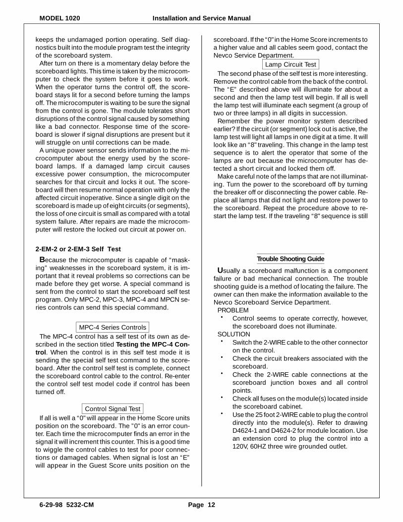
keeps the un dam aged por tion op er at ing. Self di ag -nos tics built into the mod ule pro gram test the in teg rityof the score board sys tem.
Af ter turn on there is a mo men tary de lay be fore thescore board lights. This time is taken by the mi cro com -puter to check the sys tem be fore it goes to work.When the op er a tor turns the con trol off, the score -board stays lit for a sec ond be fore turn ing the lampsoff. The mi cro com puter is wait ing to be sure the sig nalfrom the con trol is gone. The mod ule tol er ates shortdis rup tions of the con trol sig nal caused by some thinglike a bad con nec tor. Re sponse time of the score -board is slower if sig nal dis rup tions are pres ent but itwill strug gle on un til cor rec tions can be made.
A unique power sen sor sends in for ma tion to the mi -cro com puter about the en ergy used by the score -board lamps. If a dam aged lamp cir cuit causesex ces sive power con sump tion, the mi cro com putersearches for that cir cuit and locks it out. The score -board will then re sume nor mal op er a tion with only theaf fected cir cuit in op er a tive. Since a sin gle digit on thescore board is made up of eight cir cuits (or seg ments), the loss of one cir cuit is small as com pared with a to talsys tem fail ure. Af ter re pairs are made the mi cro com -puter will re store the locked out cir cuit at power on.
2-EM-2 or 2-EM-3 Self Test
Be cause the mi cro com puter is ca pa ble of “mask -ing” weak nesses in the score board sys tem, it is im -por tant that it re veal prob lems so cor rec tions can bemade be fore they get worse. A spe cial com mand issent from the con trol to start the score board self testpro gram. Only MPC-2, MPC-3, MPC-4 and MPCN se -ries con trols can send this spe cial com mand.
MPC-4 Se ries Con trols The MPC-4 con trol has a self test of its own as de -
scribed in the sec tion ti tled Testing the MPC-4 Con -trol. When the con trol is in this self test mode it issend ing the spe cial self test com mand to the score -board. Af ter the con trol self test is com plete, con nectthe score board con trol ca ble to the con trol. Re-enterthe con trol self test model code if con trol has beenturned off.
Con trol Sig nal Test If all is well a “0" will ap pear in the Home Score units
po si tion on the score board. The ”0" is an er ror coun -ter. Each time the mi cro com puter finds an er ror in thesig nal it will in cre ment this coun ter. This is a good timeto wig gle the con trol ca bles to test for poor con nec -tions or dam aged ca bles. When sig nal is lost an “E”will ap pear in the Guest Score units po si tion on the
score board. If the “0" in the Home Score in cre ments to a higher value and all ca bles seem good, con tact theNevco Ser vice De part ment.
Lamp Cir cuit Test The sec ond phase of the self test is more in ter est ing.
Re move the con trol ca ble from the back of the con trol. The “E” de scribed above will il lu mi nate for about asec ond and then the lamp test will be gin. If all is wellthe lamp test will il lu mi nate each seg ment (a group oftwo or three lamps) in all dig its in suc ces sion.
Re mem ber the power mon i tor sys tem de scribedear lier? If the cir cuit (or seg ment) lock out is ac tive, the lamp test will light all lamps in one digit at a time. It willlook like an “8" trav el ing. This change in the lamp testse quence is to alert the op er a tor that some of thelamps are out be cause the mi cro com puter has de -tected a short cir cuit and locked them off.
Make care ful note of the lamps that are not il lu mi nat -ing. Turn the power to the score board off by turn ingthe breaker off or dis con nect ing the power ca ble. Re -place all lamps that did not light and re store power tothe score board. Re peat the pro ce dure above to re -start the lamp test. If the trav el ing “8" se quence is still
Installation and Service Manual MODEL 1020
Page 13 6-29-98 5232-CM
PROB LEM• Con trol dis play does not il lu mi nate when
turned on and the score board does not il lu mi -nate.
SO LU TION• Check the fuse on the con trol.• Check the power out let for the con trol by plug -
ging in an other ap pli ance. PROB LEM• Two or three lamps in a par tic u lar nu meral do
not light.SO LU TION• Turn the power ser vice to the score board off.
Even with the con trol turned off, POWER is stillap plied to the score board mod ule(s).
• Re fer to the Mod ule End View print(s) whichshow the mod ule plug num bers and their use.Lo cate the mod ule and plug that are not work -ing prop erly. Check the plug for firm con nec -tion.
• Check the metal pins in the ny lon plug for full in -ser tion.
• In ter change the plug in ques tion with a plugthat works to de ter mine if the prob lem is in themod ule(s) or lamp bank(s). If the lamps light af -ter ex chang ing the plugs, the prob lem is in themod ule. Re turn the mod ule(s) to the NevcoScore board Ser vice De part ment for re pair. Ifthe same lamps still do not light, the trou ble is in the lamp bank. Fol low the col ored wire to itscon nec tion on the back of the lamp bank. Tocom ply with UL, you must re in stall the lampbank with pop riv ets.
PROB LEM• Two or three lamps will not turn off even with the
con trol turned off. SO LU TION • The prob lem is in the mod ule(s). Make care ful
note of the lo ca tion of the lamps and re turn thede fec tive mod ule(s) to the Nevco Score boardSer vice De part ment.
If the score board fails to op er ate prop erly af ter fol -low ing the trou ble shoot ing pro ce dure, con tact theNevco Score board Ser vice De part ment or re turn both the op er a tor’s MPC con trol and score board mod -ule(s) to the Nevco Score board Ser vice De part ment.For your pro tec tion, in sure your ship ment for fullvalue.
NOTES

MODEL 1020 Installation and Service Manual
6-29-98 5232-CM Page 14
We en cour age you to ex per i ment with the score -board fea tures to be come fa mil iar with them all. If youhave any ques tions about the con trol or the score -board, you may call the Nevco Score board Ser viceDe part ment at the num bers listed be low.
NEVCO SCOREBOARD COMPANY301 East Harris Avenue
P.O. Box 609Greenville, IL 62246-0609 USA
Fax: (618) 664-0398Telephone: (618) 664-0360
__________________________
800-851-4040 TOLL-FREEUSA, all 50 states & Puerto Rico
— IN CANADA —NEVCO SCOREBOARD COMPANY LTD.
Forestview Rd., P.O. Box 2629Orillia, ON L3V 7C1 Canada
Fax: (705) 325-8891Telephone: (800) 461-8550
Five (5) Year Guarantee
Nevco score boards are guar an teed for a pe riod offive (5) years from the date of in voice against de fectsin work man ship or ma te rial and will be re placed or re -paired with out cost to the owner pro vided the equip -ment or parts (which in cludes LED seg ments) arere turned post age-paid to the Nevco fac tory. Shippingback to the owner will be sur face post age pre paid ex -cept if air or spe cial method of re turn is spec i fied, thenship ping will be freight col lect. Lamp bulbs are ex -cluded from this guar an tee. No charges for time orma te rial used by oth ers in mak ing re pairs or cor rec -tions will be paid by Nevco Score board Com pany.Guar an tee void if: any al ter ation or ser vice, other thanun plug ging mod ules or con trols, is per formed with out Nevco fac tory au tho ri za tion; or if the equip ment shallhave been con nected to in cor rect power, or is im prop -erly grounded or im prop erly in stalled. Equip mentwhich is sub jected to ac ci dent, ne glect, abuse, mis -use or other nat u ral di sas ters, in clud ing but not lim -ited to: fire, wind, light ning, flood is not cov ered by this guar an tee.
Nevco Statement
The state ment be low is re quired by the FCC.Properly op er at ing Nevco equip ment should not in ter -fere with any other equip ment, nor should otherequip ment op er at ing prop erly in ter fere with Nevcoequip ment. This state ment is ap pli ca ble for mod elsbuilt af ter Sept. 30, 1983.
Federal Communications CommissionRequired Statement
NOTE:
This equip ment has been tested and found to com -ply with the lim its for a Class A dig i tal de vice, pur su antto Part 15 of the FCC Rules. These lim its are de signedto pro vide rea son able pro tec tion against harm ful in -ter fer ence when the equip ment is op er ated in a com -mer cial en vi ron ment. This equip ment gen er ates,uses, and can ra di ate ra dio fre quency en ergy and, ifnot in stalled and used in ac cor dance with the in struc -tion man ual, may cause harm ful in ter fer ence to ra diocom mu ni ca tions. Op er a tion of this equip ment in ares i den tial area is likely to cause harm ful in ter fer encein which case the user will be re quired to cor rect thein ter fer ence at his own ex pense.
Changes or mod i fi ca tions not ex pressly ap provedby Nevco Score board Com pany can void the user’sau thor ity to op er ate the equip ment.
Canadian Department of Communications ( D.O.C.)Statement
This dig i tal ap pa ra tus does not ex ceed the Class Alim its for Ra dio noise emis sions from dig i tal ap pa ra tus set out in the Ra dio In ter fer ence Reg u la tion of the Ca -na dian De part ment of Com mu ni ca tions.
Le présent appariel numérique n’émet pas de bruitsradioélectriques dépassant les limites applicablesaux appariels numériques de la classe A prescritesdans le Règlement sur le brouillage radioélectriqueédicté par le ministère des Com mu ni ca tions du Can -ada.
Installation and Service Manual MODEL 1020
Page 15 6-29-98 5232-CM
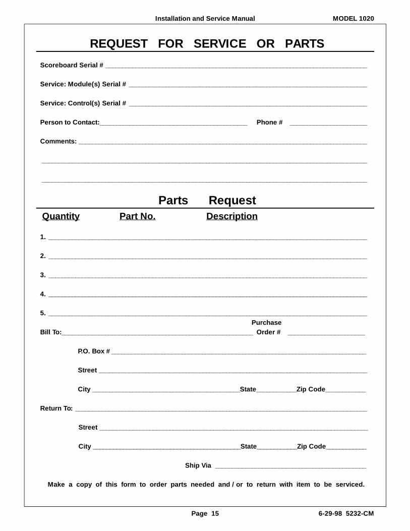
RE QUEST FOR SER VICE OR PARTS
Score board Se rial #______________________________________________________________________________
Ser vice: Mod ule(s) Se rial # _______________________________________________________________________
Ser vice: Con trol(s) Se rial # _______________________________________________________________________
Per son to Con tact:____________________________________________ Phone # _______________________
Com ments: ______________________________________________________________________________________
_________________________________________________________________________________________________
_________________________________________________________________________________________________
Parts Re questQuantity Part No. Description
1. _______________________________________________________________________________________________
2. _______________________________________________________________________________________________
3. _______________________________________________________________________________________________
4. _______________________________________________________________________________________________
5. _______________________________________________________________________________________________ Pur chaseBill To:_________________________________________________________ Or der # _______________________
P.O. Box #____________________________________________________________________________
Street ________________________________________________________________________________
City ____________________________________________State____________Zip Code____________
Re turn To: _______________________________________________________________________________________
Street ________________________________________________________________________________
City ____________________________________________State____________Zip Code____________
Ship Via _____________________________________________
Make a copy of this form to or der parts needed and / or to re turn with item to be ser viced.