modbus protocol - electro-numerics 7 - 5. modbus protocol implementation 1.0 general the modbus...
TRANSCRIPT

Modbus Protocol COMMUNICATIONS MANUAL
For Series B Digital Panel Meters, Counters and Timers
- 2 -
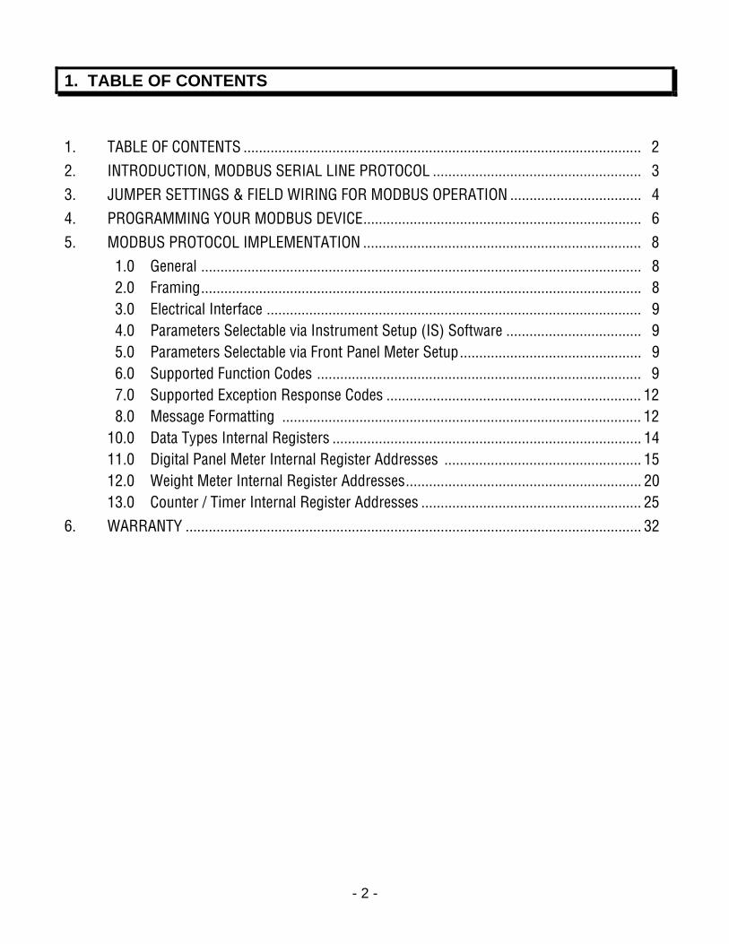
1. TABLE OF CONTENTS
1. TABLE OF CONTENTS ....................................................................................................... 2 2. INTRODUCTION, MODBUS SERIAL LINE PROTOCOL ...................................................... 3 3. JUMPER SETTINGS & FIELD WIRING FOR MODBUS OPERATION .................................. 4 4. PROGRAMMING YOUR MODBUS DEVICE........................................................................ 6 5. MODBUS PROTOCOL IMPLEMENTATION ........................................................................ 8 1.0 General .................................................................................................................. 8 2.0 Framing.................................................................................................................. 8 3.0 Electrical Interface ................................................................................................. 9 4.0 Parameters Selectable via Instrument Setup (IS) Software ................................... 9 5.0 Parameters Selectable via Front Panel Meter Setup............................................... 9 6.0 Supported Function Codes .................................................................................... 9 7.0 Supported Exception Response Codes .................................................................. 12 8.0 Message Formatting ............................................................................................. 12 10.0 Data Types Internal Registers ................................................................................ 14 11.0 Digital Panel Meter Internal Register Addresses ................................................... 15 12.0 Weight Meter Internal Register Addresses............................................................. 20 13.0 Counter / Timer Internal Register Addresses ......................................................... 25 6. WARRANTY ...................................................................................................................... 32

- 3 -
2. INTRODUCTION, MODBUS SERIAL LINE PROTOCOL The Modbus Protocol is an industry-standard serial communications protocol which can be used with RS232 or RS485 signals, but is normally only used with RS485. This is because RS232 is designed for point-to-point communications and is limited to line lengths up to 50 ft (9 m), while RS485 is designed for multidrop communications and allows line length up to 1 mile (1.6 km).
With the Modbus Protocol and RS485, up to 32 devices by different manufacturers can share the same RS485 data line without a repeater, be connected using similarly-wired RJ45 connectors, and be addressed with up to 247 digital addresses. A computer is required in a Modbus system. The Modbus Serial Line protocol is a master-slave protocol, where a master node (computer) issues commands to slave nodes (peripheral devices) on the bus and processes responses.
Modbus I/O capability is offered as an option with our Series B digital panel meters, counters and timers. The Modbus protocol is implemented by the microcomputer on the main board and is compliant with the Modbus RTU or ASCII transmission modes (software selectable).
Digital panel meters, counters and timers require a serial communications plug-in option board for use of the Modbus protocol. This can be an RS232 board, RS485 board, or Modbus board. The RS485 and Modbus boards are both RS485 compliant, but the RS485 board uses RJ11 connectors while the Modbus board uses RJ45 connectors as specified for Modbus. With the Modbus board and Modbus protocol, the instruments are fully compliant with Modbus over Serial Line Specification V1.0 (2002). This includes RJ45 connectors and 2-wire half-duplex or 4-wire full-duplex operation (jumper selectable). The two RJ45 or RJ11 connectors are wired in parallel to allow device daisy chaining with no need for a hub. One of the jacks is equipped with two indicator LEDs.
The Custom ASCII Protocol is a software-selectable alternative to the Modbus Protocol. This protocol can also be used with RS232 or RS485 signals and allows digital addressing. It is less complex than the Modbus protocol; however, it is not an industry standard. For information on the Custom ASCII Protocol, please refer to our separate Custom ASCII Protocol Communications Manual.
- 4 -
3. JUMPER SETTINGS & FIELD WIRING FOR MODBUS OPERATION
1. SAFETY WARNINGS
Digital panel meters, counters and timers
may be powered with AC (mains) from 95-240V ac ±10% or 90-300V dc with the high voltage power supply option, or 10-34V ac ±10% or 10-48 Vdc with the low voltage power supply option. To avoid the possibility of electrical shock or damaging short circuits, always unplug the device before opening the case. Please refer to the respective device manuals for full safety information and instruction on how to open the case. Signal wiring changes external to the case can be made safely while the units are under power.
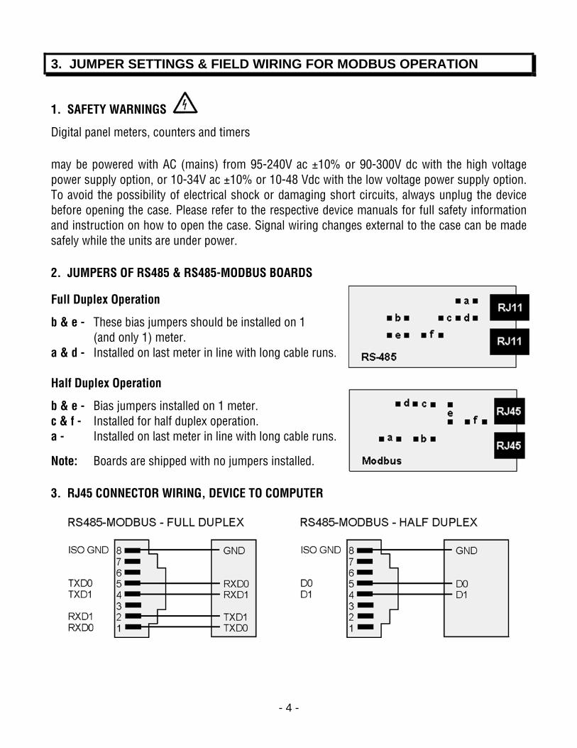
2. JUMPERS OF RS485 & RS485-MODBUS BOARDS
Full Duplex Operation
b & e - These bias jumpers should be installed on 1 (and only 1) meter.
a & d - Installed on last meter in line with long cable runs.
Half Duplex Operation
b & e - Bias jumpers installed on 1 meter. c & f - Installed for half duplex operation. a - Installed on last meter in line with long cable runs.
Note: Boards are shipped with no jumpers installed.
3. RJ45 CONNECTOR WIRING, DEVICE TO COMPUTER
- 5 -
4. PROGRAMMING YOUR MODBUS DEVICE
OVERVIEW
Modbus digital panel meters, counters and timers are easily programmed via their serial port using Windows-based Instrument Setup (IS) software, which provides a graphical user inter-face and is available at no charge. This software allows uploading, editing, downloading and saving of setup data, execution of commands under computer control, listing, plotting and graphing of data, and computer prompted calibration. Digital panel meters, counters and timers can also be programmed via their 4-key front panel as explained in their respective manuals; however, front panel programming not recommended when serial communications are available.
INSTRUMENT SETUP SOFTWARE INSTALLATION FROM CD ROM
Insert the CD ROM into your PC. The CD is self-booting and will present you with a menu of choices. Click on “Install Instrument Setup Software” and follow the prompts.
GETTING STARTED WITH IS SOFTWARE
To launch IS software, press Start = > Programs = > IS64 = > IS2. Click on your device type. The program will temporarily set the selected COM port to the selected baud rate, protocol, and parity. Once communications have been established, click on Main Menu.
The best way to learn IS software is to experiment with it. From the Main Menu, click on Get Setup to retrieve (or get) the existing setup data from your device. Click on View = > Setup to bring up screens which allow you to edit the setup file using pull-down menus and other selection tools. You can save your file to disk by clicking on File = > Save Setup. You can download (or put) your edited file into the instrument by clicking on Put Setup. Programmable items will only be displayed if you have told the software that you have the appropriate hardware, such as the dual relay option. Pressing the F1 key at any time will bring up detailed help information.
An optional analog output is defined in two steps. The input to the device is first scaled to a digital reading in engineering units, and this reading is then converted to the analog output. The digital reading is also used for setpoint control and can be transmitted as serial data.
ADDITIONAL FEATURES
• The Commands pull-down menu allows you to execute certain functions by using your computer mouse. The Commands pull-down menu will be grayed out unless a Get Setup has been executed.
• The Readings pull-down menu provides three formats to display input data on your PC monitor. In all formats, use the Pause and Continue buttons to control the timing of data collection, then press Print for a hardcopy on your PC printer.

- 6 -
- List presents the latest digital readings in a 20-row by 10-column table. Press Pause at any time to freeze the display. Press Print for a hardcopy.
- Plot generates a plot of digital readings vs. time in seconds. It effectively turns the instrument-PC combination into a printing digital oscilloscope.
- Graph generates a histogram, where the horizontal axis is the reading and the vertical axis is the number of readings. The display continually resizes itself as the number of readings increases.

- 7 -
5. MODBUS PROTOCOL IMPLEMENTATION
1.0 GENERAL
The Modbus capability conforms to the Modbus over Serial Line Specification & Implemen-tation guide, V1.0. Both the Modbus RTU and Modbus ASCII protocols are implemented:
Modbus RTU
Baud Rate........... 300, 600, 1200, 2400, 4800, 9600 or 19200 Data Format ....... 1 start bit, 8 data bits, 1 parity bit, 1 stop bit (11 bits total) Parity.................. None, Odd, Even (if None, then 2 Stop bits for 11 total) Address.............. 0 for broadcast, 1-247 for individual meters
Modbus ASCII
Baud Rate........... 300, 600, 1200, 2400, 4800, 9600 or 19200 Data Format ....... 1 Start bit, 7 Data bits, 1 Parity bit, 1 Stop bit (10 bits total) Parity.................. None, Odd, Even (if None, then 2 Stop bits for 10 total) Address.............. 0 for broadcast, 1-247 for individual meters
2.0 FRAMING
Modbus RTU
Message frames are separated by a silent interval of at least 3.5 character times. If a silent interval of more than 1.5 character times occurs between two characters of the message frame, the message frame is considered incomplete and is discarded. Frame Check = 16 bit CRC of the complete message excluding CRC characters.
Modbus ASCII
The message begins immediately following a colon (:) and ends just before a Carriage Return/ Line Feed (CRLF). All message characters are hexadecimal 0-9, A-F (ASCII coded). The system allowable time interval between characters may be set to 1, 3, 5 or 10 seconds. Frame Check = 1 byte (2 hexadecimal characters) LRC of the message excluding the initial colon (:) and trailing LRC and CRLF characters.
3.0 ELECTRICAL INTERFACE
Four-wire (plus common) full-duplex or two-wire (plus common) half-duplex RS485 signal levels are jumper selectable for digital panel meters, counters and timers. A polarization resistor and termination resistor are also jumper selectable. In case of a long line (greater then 500 ft) to the first device, a termination resistor should be selected for the first device. In case of a long line length (greater then 500 ft) between the first and last devices, a termination resistor should be selected for the first and last devices. Never add termination resistors to more than two devices on the same line.
- 8 -
4.0 PARAMETERS SELECTABLE VIA INSTRUMENT SETUP (IS) SOFTWARE
Serial Protocol ...............................Custom ASCII, Modbus RTU, Modbus ASCII Modbus ASCII Gap Timeout...........1 sec, 3 sec, 5 sec, 10 sec Baud Rate.......................................300, 600, 1200, 2400, 4800, 9600, 19200 Parity .............................................No parity, odd parity, even parity Device Address .............................0 to 247
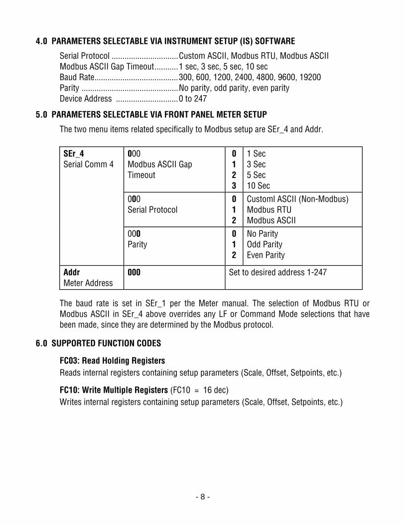
5.0 PARAMETERS SELECTABLE VIA FRONT PANEL METER SETUP
The two menu items related specifically to Modbus setup are SEr_4 and Addr.
000 Modbus ASCII Gap Timeout
0 1 2 3
1 Sec 3 Sec 5 Sec 10 Sec
000 Serial Protocol
0 1 2
Customl ASCII (Non-Modbus) Modbus RTU Modbus ASCII
SEr_4 Serial Comm 4
000 Parity
0 1 2
No Parity Odd Parity Even Parity
Addr Meter Address
000 Set to desired address 1-247
The baud rate is set in SEr_1 per the Meter manual. The selection of Modbus RTU or Modbus ASCII in SEr_4 above overrides any LF or Command Mode selections that have been made, since they are determined by the Modbus protocol.
6.0 SUPPORTED FUNCTION CODES
FC03: Read Holding Registers Reads internal registers containing setup parameters (Scale, Offset, Setpoints, etc.)
FC10: Write Multiple Registers (FC10 = 16 dec) Writes internal registers containing setup parameters (Scale, Offset, Setpoints, etc.)
- 9 -
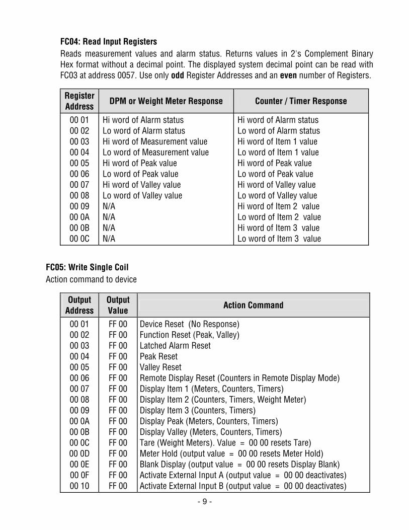
FC04: Read Input Registers Reads measurement values and alarm status. Returns values in 2's Complement Binary Hex format without a decimal point. The displayed system decimal point can be read with FC03 at address 0057. Use only odd Register Addresses and an even number of Registers.
Register Address
DPM or Weight Meter Response Counter / Timer Response
00 01 00 02 00 03 00 04 00 05 00 06 00 07 00 08 00 09 00 0A 00 0B 00 0C
Hi word of Alarm status Lo word of Alarm status Hi word of Measurement value Lo word of Measurement value Hi word of Peak value Lo word of Peak value Hi word of Valley value Lo word of Valley value N/A N/A N/A N/A
Hi word of Alarm status Lo word of Alarm status Hi word of Item 1 value Lo word of Item 1 value Hi word of Peak value Lo word of Peak value Hi word of Valley value Lo word of Valley value Hi word of Item 2 value Lo word of Item 2 value Hi word of Item 3 value Lo word of Item 3 value
FC05: Write Single Coil Action command to device
Output Address
Output Value
Action Command
00 01 00 02 00 03 00 04 00 05 00 06 00 07 00 08 00 09 00 0A 00 0B 00 0C 00 0D 00 0E 00 0F 00 10
FF 00 FF 00 FF 00 FF 00 FF 00 FF 00 FF 00 FF 00 FF 00 FF 00 FF 00 FF 00 FF 00 FF 00 FF 00 FF 00
Device Reset (No Response) Function Reset (Peak, Valley) Latched Alarm Reset Peak Reset Valley Reset Remote Display Reset (Counters in Remote Display Mode) Display Item 1 (Meters, Counters, Timers) Display Item 2 (Counters, Timers, Weight Meter) Display Item 3 (Counters, Timers) Display Peak (Meters, Counters, Timers) Display Valley (Meters, Counters, Timers) Tare (Weight Meters). Value = 00 00 resets Tare) Meter Hold (output value = 00 00 resets Meter Hold) Blank Display (output value = 00 00 resets Display Blank) Activate External Input A (output value = 00 00 deactivates) Activate External Input B (output value = 00 00 deactivates)
- 10 -
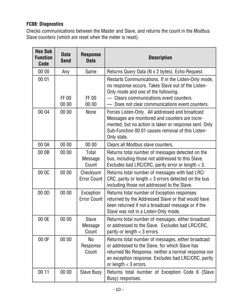
FC08: Diagnostics Checks communications between the Master and Slave, and returns the count in the Modbus Slave counters (which are reset when the meter is reset).
Hex Sub Function
Code
Data Send
Response Data Description
00 00 Any Same Returns Query Data (N x 2 bytes). Echo Request. 00 01
FF 00 00 00
FF 00 00 00
Restarts Communications. If in the Listen-Only mode, no response occurs. Takes Slave out of the Listen-Only mode and one of the following: — Clears communications event counters. — Does not clear communications event counters.
00 04 00 00 None Forces Listen-Only. All addressed and broadcast Messages are monitored and counters are incre-mented, but no action is taken or response sent. Only Sub-Function 00 01 causes removal of this Listen-Only state.
00 0A 00 00 00 00 Clears all Modbus slave counters. 00 0B 00 00 Total
Message Count
Returns total number of messages detected on the bus, including those not addressed to this Slave. Excludes bad LRC/CRC, parity error or length < 3.
00 0C 00 00 Checksum Error Count
Returns total number of messages with bad LRC/ CRC, parity or length < 3 errors detected on the bus including those not addressed to the Slave.
00 0D 00 00 Exception Error Count
Returns total number of Exception responses returned by the Addressed Slave or that would have been returned if not a broadcast message or if the Slave was not in a Listen-Only mode.
00 0E 00 00 Slave Message
Count
Returns total number of messages, either broadcast or addressed to the Slave. Excludes bad LRC/CRC, parity or length < 3 errors.
00 0F 00 00 No Response
Count
Returns total number of messages, either broadcast or addressed to the Slave, for which Slave has returned No Response, neither a normal response nor an exception response. Excludes bad LRC/CRC, parity or length < 3 errors.
00 11 00 00 Slave Busy Returns total number of Exception Code 6 (Slave Busy) responses.
- 11 -
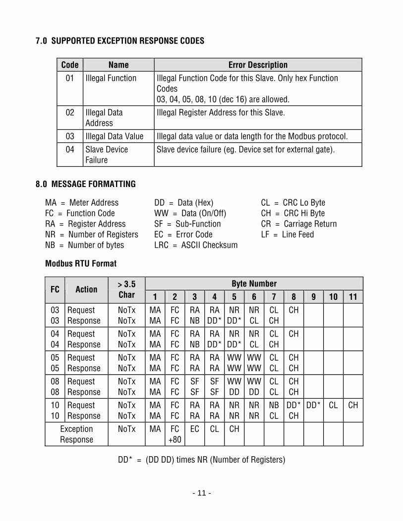
7.0 SUPPORTED EXCEPTION RESPONSE CODES
Code Name Error Description 01 Illegal Function Illegal Function Code for this Slave. Only hex Function
Codes 03, 04, 05, 08, 10 (dec 16) are allowed.
02 Illegal Data Address
Illegal Register Address for this Slave.
03 Illegal Data Value Illegal data value or data length for the Modbus protocol. 04 Slave Device
Failure Slave device failure (eg. Device set for external gate).
8.0 MESSAGE FORMATTING
MA = Meter Address DD = Data (Hex) CL = CRC Lo Byte FC = Function Code WW = Data (On/Off) CH = CRC Hi Byte RA = Register Address SF = Sub-Function CR = Carriage Return NR = Number of Registers EC = Error Code LF = Line Feed NB = Number of bytes LRC = ASCII Checksum
Modbus RTU Format
Byte Number FC Action > 3.5
Char 1 2 3 4 5 6 7 8 9 10 11 03 03
Request Response
NoTx NoTx
MA MA
FC FC
RA NB
RA DD*
NR DD*
NR CL
CL CH
CH
04 04
Request Response
NoTx NoTx
MA MA
FC FC
RA NB
RA DD*
NR DD*
NR CL
CL CH
CH
05 05
Request Response
NoTx NoTx
MA MA
FC FC
RA RA
RA RA
WWWW
WWWW
CL CL
CH CH
08 08
Request Response
NoTx NoTx
MA MA
FC FC
SF SF
SF SF
WWDD
WWDD
CL CL
CH CH
10 10
Request Response
NoTx NoTx
MA MA
FC FC
RA RA
RA RA
NR NR
NR NR
NB CL
DD* CH
DD* CL CH
Exception Response
NoTx MA FC+80
EC CL CH
DD* = (DD DD) times NR (Number of Registers)
- 12 -
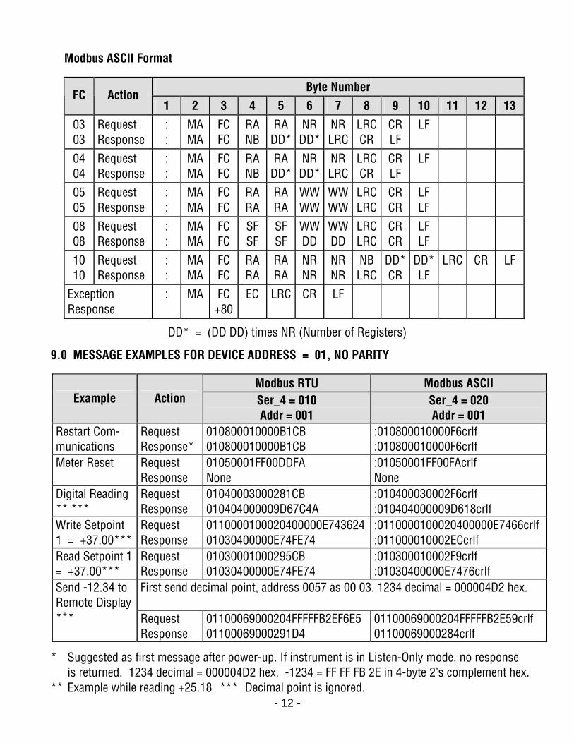
Modbus ASCII Format
Byte Number FC Action
1 2 3 4 5 6 7 8 9 10 11 12 13 03 03
Request Response
: :
MA MA
FC FC
RA NB
RA DD*
NR DD*
NR LRC
LRCCR
CR LF
LF
04 04
Request Response
: :
MA MA
FC FC
RA NB
RA DD*
NR DD*
NR LRC
LRCCR
CR LF
LF
05 05
Request Response
: :
MA MA
FC FC
RA RA
RA RA
WWWW
WWWW
LRCLRC
CR CR
LF LF
08 08
Request Response
: :
MA MA
FC FC
SF SF
SF SF
WWDD
WWDD
LRCLRC
CR CR
LF LF
10 10
Request Response
: :
MA MA
FC FC
RA RA
RA RA
NR NR
NR NR
NB LRC
DD* CR
DD* LF
LRC CR LF
Exception Response
: MA FC +80
EC LRC CR LF
DD* = (DD DD) times NR (Number of Registers)
9.0 MESSAGE EXAMPLES FOR DEVICE ADDRESS = 01, NO PARITY
Modbus RTU Modbus ASCII Example Action Ser_4 = 010
Addr = 001 Ser_4 = 020 Addr = 001
Restart Com-munications
Request Response*
010800010000B1CB 010800010000B1CB
:010800010000F6crlf :010800010000F6crlf
Meter Reset Request Response
01050001FF00DDFA None
:01050001FF00FAcrlf None
Digital Reading ** ***
Request Response
01040003000281CB 010404000009D67C4A
:010400030002F6crlf :010404000009D618crlf
Write Setpoint 1 = +37.00***
Request Response
0110000100020400000E74362401030400000E74FE74
:0110000100020400000E7466crlf :011000010002ECcrlf
Read Setpoint 1 = +37.00***
Request Response
01030001000295CB 01030400000E74FE74
:010300010002F9crlf :01030400000E7476crlf
First send decimal point, address 0057 as 00 03. 1234 decimal = 000004D2 hex.
Send -12.34 to Remote Display *** Request
Response 01100069000204FFFFFB2EF6E5 01100069000291D4
01100069000204FFFFFB2E59crlf 01100069000284crlf
* Suggested as first message after power-up. If instrument is in Listen-Only mode, no response is returned. 1234 decimal = 000004D2 hex. -1234 = FF FF FB 2E in 4-byte 2’s complement hex.
** Example while reading +25.18 *** Decimal point is ignored.
- 13 -
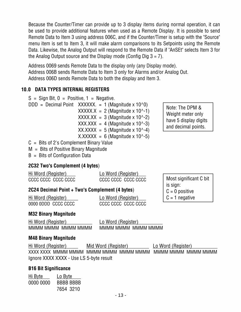
Because the Counter/Timer can provide up to 3 display items during normal operation, it can be used to provide additional features when used as a Remote Display. It is possible to send Remote Data to Item 3 using address 006C, and if the Counter/Timer is setup with the "Source" menu item is set to Item 3, it will make alarm comparisons to its Setpoints using the Remote Data. Likewise, the Analog Output will respond to the Remote Data if "AnSEt" selects Item 3 for the Analog Output source and the Display mode (Config Dig 3 = 7).
Address 0069 sends Remote Data to the display only (any Display mode). Address 006B sends Remote Data to Item 3 only for Alarms and/or Analog Out. Address 006D sends Remote Data to both the display and Item 3.
10.0 DATA TYPES INTERNAL REGISTERS
S = Sign Bit, 0 = Positive, 1 = Negative. DDD = Decimal Point XXXXXX. = 1 (Magnitude x 10^0)
XXXXX.X = 2 (Magnitude x 10^-1) XXXX.XX = 3 (Magnitude x 10^-2) XXX.XXX = 4 (Magnitude x 10^-3) XX.XXXX = 5 (Magnitude x 10^-4) X.XXXXX = 6 (Magnitude x 10^-5)
C = Bits of 2's Complement Binary Value M = Bits of Positive Binary Magnitude B = Bits of Configuration Data
2C32 Two's Complement (4 bytes) Hi Word (Register) Lo Word (Register) . CCCC CCCC CCCC CCCC CCCC CCCC CCCC CCCC
2C24 Decimal Point + Two's Complement (4 bytes) Hi Word (Register) Lo Word (Register) . 0000 0DDD CCCC CCCC CCCC CCCC CCCC CCCC
M32 Binary Magnitude Hi Word (Register) Lo Word (Register) . MMMM MMMM MMMM MMMM MMMM MMMM MMMM MMMM
M48 Binary Magnitude Hi Word (Register) Mid Word (Register) Lo Word (Register) . XXXX XXXX MMMM MMMM MMMM MMMM MMMM MMMM MMMM MMMM MMMM MMMM Ignore XXXX XXXX - Use LS 5-byte result
B16 Bit Significance Hi Byte Lo Byte . 0000 0000 BBBB BBBB
7654 3210
Note: The DPM & Weight meter only have 5 display digits and decimal points.
Most significant C bit is sign: C = 0 positive C = 1 negative
- 14 -
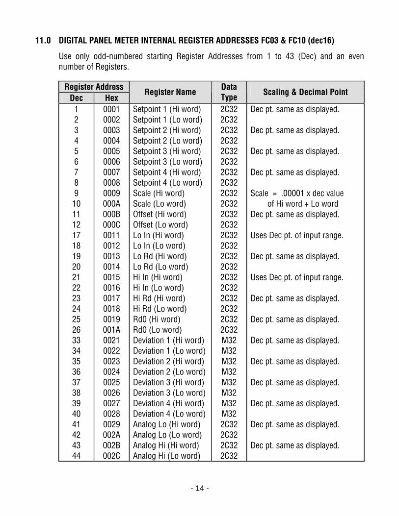
11.0 DIGITAL PANEL METER INTERNAL REGISTER ADDRESSES FC03 & FC10 (dec16)
Use only odd-numbered starting Register Addresses from 1 to 43 (Dec) and an even number of Registers.
Register Address
Dec Hex Register Name Data
Type Scaling & Decimal Point
1 2 3 4 5 6 7 8 9 10 11 12 17 18 19 20 21 22 23 24 25 26 33 34 35 36 37 38 39 40 41 42 43 44
0001 0002 0003 0004 0005 0006 0007 0008 0009 000A 000B 000C 0011 0012 0013 0014 0015 0016 0017 0018 0019 001A 0021 0022 0023 0024 0025 0026 0027 0028 0029 002A 002B 002C
Setpoint 1 (Hi word) Setpoint 1 (Lo word) Setpoint 2 (Hi word) Setpoint 2 (Lo word) Setpoint 3 (Hi word) Setpoint 3 (Lo word) Setpoint 4 (Hi word) Setpoint 4 (Lo word) Scale (Hi word) Scale (Lo word) Offset (Hi word) Offset (Lo word) Lo In (Hi word) Lo In (Lo word) Lo Rd (Hi word) Lo Rd (Lo word) Hi In (Hi word) Hi In (Lo word) Hi Rd (Hi word) Hi Rd (Lo word) Rd0 (Hi word) Rd0 (Lo word) Deviation 1 (Hi word) Deviation 1 (Lo word) Deviation 2 (Hi word) Deviation 2 (Lo word) Deviation 3 (Hi word) Deviation 3 (Lo word) Deviation 4 (Hi word) Deviation 4 (Lo word) Analog Lo (Hi word) Analog Lo (Lo word) Analog Hi (Hi word) Analog Hi (Lo word)
2C32 2C32 2C32 2C32 2C32 2C32 2C32 2C32 2C32 2C32 2C32 2C32 2C32 2C32 2C32 2C32 2C32 2C32 2C32 2C32 2C32 2C32 M32 M32 M32 M32 M32 M32 M32 M32 2C32 2C32 2C32 2C32
Dec pt. same as displayed. Dec pt. same as displayed. Dec pt. same as displayed. Dec pt. same as displayed. Scale = .00001 x dec value of Hi word + Lo word Dec pt. same as displayed. Uses Dec pt. of input range. Dec pt. same as displayed. Uses Dec pt. of input range. Dec pt. same as displayed. Dec pt. same as displayed. Dec pt. same as displayed. Dec pt. same as displayed. Dec pt. same as displayed. Dec pt. same as displayed. Dec pt. same as displayed. Dec pt. same as displayed.

- 15 -
For the following, use any starting Register Address and any number of Registers. The data type is B16, except for FC10 dec 16, where the data type is 2C32. Register Address
Dec Hex Register Name Bit Significance
65
0041 Alarm Config 1 Bit 0 0 = AL1 Hi Active 1 = Lo Active Bit 1 0 = AL1 Enabled, 1 = Disabled Bit 2 0 = AL2 Hi Active 1 = Lo Active Bit 3 0 = AL2 Enabled 1 = Disabled Bit 4 0 = AL1 Non-Latched 1 = Latched Bit 5 0 = AL2 Non-Latched 1 = Latched Bit 6 0 = Relay1 Active On 1 = Off Bit 7 0 = Relay2 Active On 1 = Off
66 0042 Alarm Config 2 Bits 2:0 # Readings before Alarms 1 & 2. 000 = 1, 001 = 2, 010 = 4, 011 = 8, 100 = 16, 101 = 32, 110 = 64, 111 = 128 Bit 3 AL1 0 = Deviation 1 = Hysteresis Bit 4 AL2 0 = Deviation 1 = Hysteresis Bit 5 0 = Deviation in Menu 1 = Omitted
67 0043 Alarm Config 3 (Alarms 3 & 4 are planned developments)
Bit 0 0 = AL3 Hi Active 1 = Lo Active Bit 1 0 = AL3 Enabled 1 = Disabled Bit 2 0 = AL4 Hi Active 1 = Lo Active Bit 3 0 = AL4 Enabled 1 = Disabled Bit 4 0 = AL3 Non-Latched 1 = Latched Bit 5 0 = AL4 Non-Latched 1 = Latched Bit 6 0 = Relay3 Active On 1 = Off Bit 7 0 = Relay4 Active On 1 = Off
68 0044 Alarm Config 4 (Alarms 3 & 4 are planned developments)
Bits 2:0 = # Readings before Alarm 3 & 4 000 = 1, 001 = 2, 010 = 4, 011 = 8, 100 = 16, 101 = 32 110 = 64 111 = 128 Bit 3 AL3 0 = Deviation 1 = Hysteresis Bit 4 AL4 0 = Deviation 1 = Hysteresis Bit 5 0 = Deviation in Menu 1 = Omitted
69 0045 Input Type Lo Byte Hex value 40-4D Thermocouple JF, C, KF, KC, NF, NC, EF, EC, TF, TC, SF, SC, RF, RC 50-5C RTD 4dinF, 4dinC, 4ansiF, 4ansiC, 3dinF, 3dinC, 3ansiF, 3ansiC, 2dinF, 2dinC, 2ansiF, 2ansiC, Short 60-64 DC 0.2V, 2V, 20V, 200V, 660V 70-73 DC 2 mA, 20 mA, 200 mA, 5A A0-A2 Ratio 0.2V, 2V, 20V
- 16 -
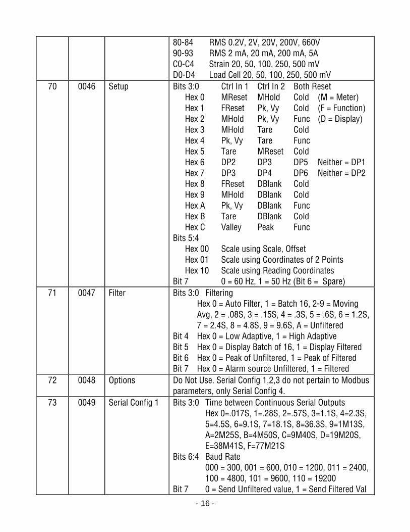
80-84 RMS 0.2V, 2V, 20V, 200V, 660V 90-93 RMS 2 mA, 20 mA, 200 mA, 5A C0-C4 Strain 20, 50, 100, 250, 500 mV D0-D4 Load Cell 20, 50, 100, 250, 500 mV
70 0046 Setup Bits 3:0 Ctrl In 1 Ctrl In 2 Both Reset Hex 0 MReset MHold Cold (M = Meter) Hex 1 FReset Pk, Vy Cold (F = Function) Hex 2 MHold Pk, Vy Func (D = Display) Hex 3 MHold Tare Cold Hex 4 Pk, Vy Tare Func Hex 5 Tare MReset Cold Hex 6 DP2 DP3 DP5 Neither = DP1 Hex 7 DP3 DP4 DP6 Neither = DP2 Hex 8 FReset DBlank Cold Hex 9 MHold DBlank Cold Hex A Pk, Vy DBlank Func Hex B Tare DBlank Cold Hex C Valley Peak Func Bits 5:4 Hex 00 Scale using Scale, Offset Hex 01 Scale using Coordinates of 2 Points Hex 10 Scale using Reading Coordinates Bit 7 0 = 60 Hz, 1 = 50 Hz (Bit 6 = Spare)
71 0047 Filter Bits 3:0 Filtering Hex 0 = Auto Filter, 1 = Batch 16, 2-9 = Moving Avg, 2 = .08S, 3 = .15S, 4 = .3S, 5 = .6S, 6 = 1.2S, 7 = 2.4S, 8 = 4.8S, 9 = 9.6S, A = Unfiltered Bit 4 Hex 0 = Low Adaptive, 1 = High Adaptive Bit 5 Hex 0 = Display Batch of 16, 1 = Display Filtered Bit 6 Hex 0 = Peak of Unfiltered, 1 = Peak of Filtered Bit 7 Hex 0 = Alarm source Unfiltered, 1 = Filtered
72 0048 Options Do Not Use. Serial Config 1,2,3 do not pertain to Modbus parameters, only Serial Config 4.
73 0049 Serial Config 1 Bits 3:0 Time between Continuous Serial Outputs Hex 0=.017S, 1=.28S, 2=.57S, 3=1.1S, 4=2.3S, 5=4.5S, 6=9.1S, 7=18.1S, 8=36.3S, 9=1M13S, A=2M25S, B=4M50S, C=9M40S, D=19M20S, E=38M41S, F=77M21S Bits 6:4 Baud Rate 000 = 300, 001 = 600, 010 = 1200, 011 = 2400, 100 = 4800, 101 = 9600, 110 = 19200 Bit 7 0 = Send Unfiltered value, 1 = Send Filtered Val

- 17 -
74 004A Serial Config 2 Bits 4:0 Meter Serial Address (0-31) [Non-Modbus] Hex 0 = Broadcast (01 = 1 to 0A = 10), 0F = 15, 10 = 16, 1F = 31 Bit 5 0 = Continuous Mode, 1 = Command Mode Bit 6 0 = No Alarm data with readings, 1 = Alarm dataBit 7 0 = No LF following CR, 1 = LF following CR
75 004B Serial Config 3 Bits 2:0 Data sent in serial output 0 = Reading, 1 = Peak, 2 = Valley, 3 = Rdg + Peak, 4 = Rdg + Valley, 5 = Rdg + Peak + Valley Bit 3 0 = Termination chars at end of all items 1 = " " at end of each item Bit 4 0 = Non-latching, RTS 1 = Latching RTS Bit 5 0 = Normal continuous serial transmission 1 = Special Start & Stop characters Bit 6 0 = Full Duplex, 1 = Half Duplex
76 004C Serial Config 4 Bits 1:0 00 = No Parity, 01 = Odd Parity, 11 = Even Parity Bits 3:2 00 = Custom ASCII, 01 = Modbus RTU, 10 = Modbus ASCII Bits 5:4 Modbus ASCII Gap Timeout 00 = 1S, 01 = 3S, 10 = 5S, 11 = 10S
77 004D Config Bit 0 0 = Linear Curve, 1 = Custom Curve Bits 2:1 Spare Bits 4:3 Peak button display response 00 = Peak, 01 = Valley, 10 = Peak then Valley, 11 = Tare Bits 7:5 000 = Not Rate, 001 = Rate x 0.1, 010 = Rate x 1, 011 = Rate x 10, 100 = Rate x 100, 101 = Rate x 1000, 110 = Rate x 10000
78 004E Lockout 1 0 = Enabled, 1 = Locked out Bit 0 Offset, Lo , Hi Read Bit 1 Scale, Lo, Hi In Bit 2 Filter Bit 3 Setup, Config, DP Bit 4 Input Type
- 18 -
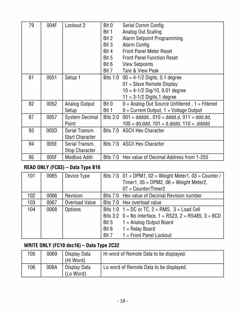
79 004F Lockout 2 Bit 0 Serial Comm Config Bit 1 Analog Out Scaling Bit 2 Alarm Setpoint Programming Bit 3 Alarm Config Bit 4 Front Panel Meter Reset Bit 5 Front Panel Function Reset Bit 6 View Setpoints Bit 7 Tare & View Peak
81 0051 Setup 1 Bits 1:0 00 = 4-1/2 Digits, 0.1 degree 01 = Slave Remote Display 10 = 4-1/2 Dig/10, 0.01 degree 11 = 3-1/2 Digits,1 degree
82 0052 Analog Output Setup
Bit 0 0 = Analog Out Source Unfiltered , 1 = Filtered Bit 1 0 = Current Output, 1 = Voltage Output
87 0057 System Decimal Point
Bits 2:0 001 = ddddd., 010 = dddd.d, 011 = ddd.dd, 100 = dd.ddd, 101 = d.dddd, 110 = .ddddd
93 005D Serial Transm. Start Character
Bits 7:0 ASCII Hex Character
94 005E Serial Transm. Stop Character
Bits 7:0 ASCII Hex Character
95 005F Modbus Addr. Bits 7:0 Hex value of Decimal Address from 1-255
READ ONLY (FC03) – Data Type B16
101 0065 Device Type Bits 7:0 01 = DPM1, 02 = Weight Meter1, 03 = Counter / Timer1, 05 = DPM2, 06 = Weight Meter2, 07 = Counter/Timer2
102 0066 Revision Bits 7:0 Hex value of Decimal Revision number 103 0067 Overload Value Bits 7:0 Hex overload value 104 0068 Options Bits 1:0 1 = DC or TC, 2 = RMS, 3 = Load Cell
Bits 3:2 0 = No Interface, 1 = RS23, 2 = RS485, 3 = BCDBit 5 1 = Analog Output Board Bit 6 1 = Relay Board Bit 7 1 = Front Panel Lockout
WRITE ONLY (FC10 dec16) – Data Type 2C32
105 0069 Display Data (Hi Word)
Hi word of Remote Data to be displayed.
106 006A Display Data (Lo Word)
Lo word of Remote Data to be displayed.
- 19 -
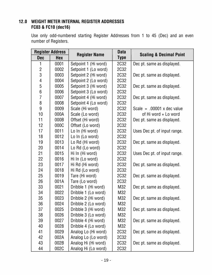
12.0 WEIGHT METER INTERNAL REGISTER ADDRESSES FC03 & FC10 (dec16)
Use only odd-numbered starting Register Addresses from 1 to 45 (Dec) and an even number of Registers.
Register Address
Dec Hex Register Name Data
Type Scaling & Decimal Point
1 2 3 4 5 6 7 8 9 10 11 12 17 18 19 20 21 22 23 24 25 26 33 34 35 36 37 38 39 40 41 42 43 44
0001 0002 0003 0004 0005 0006 0007 0008 0009 000A 000B 000C 0011 0012 0013 0014 0015 0016 0017 0018 0019 001A 0021 0022 0023 0024 0025 0026 0027 0028 0029 002A 002B 002C
Setpoint 1 (Hi word) Setpoint 1 (Lo word) Setpoint 2 (Hi word) Setpoint 2 (Lo word) Setpoint 3 (Hi word) Setpoint 3 (Lo word) Setpoint 4 (Hi word) Setpoint 4 (Lo word) Scale (Hi word) Scale (Lo word) Offset (Hi word) Offset (Lo word) Lo In (Hi word) Lo In (Lo word) Lo Rd (Hi word) Lo Rd (Lo word) Hi In (Hi word) Hi In (Lo word) Hi Rd (Hi word) Hi Rd (Lo word) Tare (Hi word) Tare (Lo word) Dribble 1 (Hi word) Dribble 1 (Lo word) Dribble 2 (Hi word) Dribble 2 (Lo word) Dribble 3 (Hi word) Dribble 3 (Lo word) Dribble 4 (Hi word) Dribble 4 (Lo word) Analog Lo (Hi word) Analog Lo (Lo word) Analog Hi (Hi word) Analog Hi (Lo word)
2C32 2C32 2C32 2C32 2C32 2C32 2C32 2C32 2C32 2C32 2C32 2C32 2C32 2C32 2C32 2C32 2C32 2C32 2C32 2C32 2C32 2C32 M32 M32 M32 M32 M32 M32 M32 M32 2C32 2C32 2C32 2C32
Dec pt. same as displayed. Dec pt. same as displayed. Dec pt. same as displayed. Dec pt. same as displayed. Scale = .00001 x dec value of Hi word + Lo word Dec pt. same as displayed. Uses Dec pt. of input range. Dec pt. same as displayed. Uses Dec pt. of input range. Dec pt. same as displayed. Dec pt. same as displayed. Dec pt. same as displayed. Dec pt. same as displayed. Dec pt. same as displayed. Dec pt. same as displayed. Dec pt. same as displayed. Dec pt. same as displayed.
- 20 -
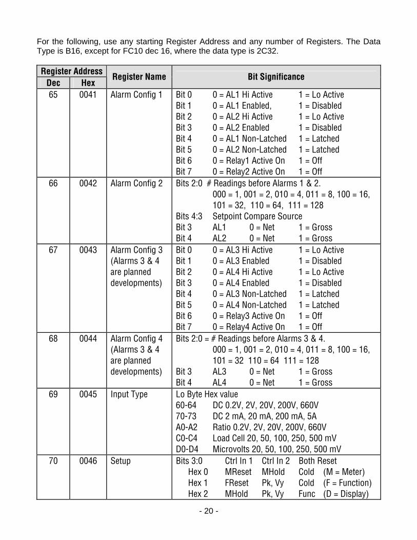
For the following, use any starting Register Address and any number of Registers. The Data Type is B16, except for FC10 dec 16, where the data type is 2C32. Register Address
Dec Hex Register Name Bit Significance
65
0041 Alarm Config 1 Bit 0 0 = AL1 Hi Active 1 = Lo Active Bit 1 0 = AL1 Enabled, 1 = Disabled Bit 2 0 = AL2 Hi Active 1 = Lo Active Bit 3 0 = AL2 Enabled 1 = Disabled Bit 4 0 = AL1 Non-Latched 1 = Latched Bit 5 0 = AL2 Non-Latched 1 = Latched Bit 6 0 = Relay1 Active On 1 = Off Bit 7 0 = Relay2 Active On 1 = Off
66 0042 Alarm Config 2 Bits 2:0 # Readings before Alarms 1 & 2. 000 = 1, 001 = 2, 010 = 4, 011 = 8, 100 = 16, 101 = 32, 110 = 64, 111 = 128 Bits 4:3 Setpoint Compare Source Bit 3 AL1 0 = Net 1 = Gross Bit 4 AL2 0 = Net 1 = Gross
67 0043 Alarm Config 3 (Alarms 3 & 4 are planned developments)
Bit 0 0 = AL3 Hi Active 1 = Lo Active Bit 1 0 = AL3 Enabled 1 = Disabled Bit 2 0 = AL4 Hi Active 1 = Lo Active Bit 3 0 = AL4 Enabled 1 = Disabled Bit 4 0 = AL3 Non-Latched 1 = Latched Bit 5 0 = AL4 Non-Latched 1 = Latched Bit 6 0 = Relay3 Active On 1 = Off Bit 7 0 = Relay4 Active On 1 = Off
68 0044 Alarm Config 4 (Alarms 3 & 4 are planned developments)
Bits 2:0 = # Readings before Alarms 3 & 4. 000 = 1, 001 = 2, 010 = 4, 011 = 8, 100 = 16, 101 = 32 110 = 64 111 = 128 Bit 3 AL3 0 = Net 1 = Gross Bit 4 AL4 0 = Net 1 = Gross
69 0045 Input Type Lo Byte Hex value 60-64 DC 0.2V, 2V, 20V, 200V, 660V 70-73 DC 2 mA, 20 mA, 200 mA, 5A A0-A2 Ratio 0.2V, 2V, 20V, 200V, 660V C0-C4 Load Cell 20, 50, 100, 250, 500 mV D0-D4 Microvolts 20, 50, 100, 250, 500 mV
70 0046 Setup Bits 3:0 Ctrl In 1 Ctrl In 2 Both Reset Hex 0 MReset MHold Cold (M = Meter) Hex 1 FReset Pk, Vy Cold (F = Function) Hex 2 MHold Pk, Vy Func (D = Display)

- 21 -
Hex 3 MHold Tare Tare Hex 4 Pk, Vy Tare Func Hex 5 MReset Tare Cold Hex 6 FReset Tare Cold Hex 7 TReset Tare Cold Hex 8 DBlank Tare Cold Hex 9 MReset DBlank Cold Hex A FReset DBlank Cold Hex B DItem2 Tare Tare Hex C Valley Peak Func Hex D MReset DItem2 Cold Hex E FReset DItem2 Cold Hex F MHold DItem2 Cold Bits 5:4 Hex 00 Scale using Scale, Offset Hex 01 Scale using Coordinates of 2 Points Hex 10 Scale using Reading Coordinates Bit 7 0 = 60 Hz, 1 = 50 Hz (Bit 6 = Spare)
71 0047 Filter Bits 3:0 Filtering Hex 0 = Auto Filter, 1 = Batch 16, 2-9 = Moving Avg, 2 = .08S, 3 = .15S, 4 = .3S, 5 = .6S, 6 = 1.2S, 7 = 2.4S, 8 = 4.8S, 9 = 9.6S, A = Unfiltered Bit 4 Hex 0 = Low Adaptive, 1 = High Adaptive Bit 5 Hex 0 = Display Batch of 16, 1 = Display Filtered Bit 6 Hex 0 = Peak of Unfiltered, 1 = Peak of Filtered Bit 7 Hex 0 = Alarm source Unfiltered, 1 = Filtered
72 0048 Options Do Not Use. Serial Config 1,2,3 do not pertain to Modbus parameters, only Serial Config 4.
73 0049 Serial Config 1 Bits 3:0 Time between Continuous Serial Outputs Hex 0=.017S, 1=.28S, 2=.57S, 3=1.1S, 4=2.3S, 5=4.5S, 6=9.1S, 7=18.1S, 8=36.3S, 9=1M13S, A=2M25S, B=4M50S, C=9M40S, D=19M20S, E=38M41S, F=77M21S Bits 6:4 Baud Rate 000 = 300, 001 = 600, 010 = 1200, 011 = 2400, 100 = 4800, 101 = 9600, 110 = 19200 Bit 7 0 = Send Unfiltered value, 1 = Send Filtered Val
- 22 -
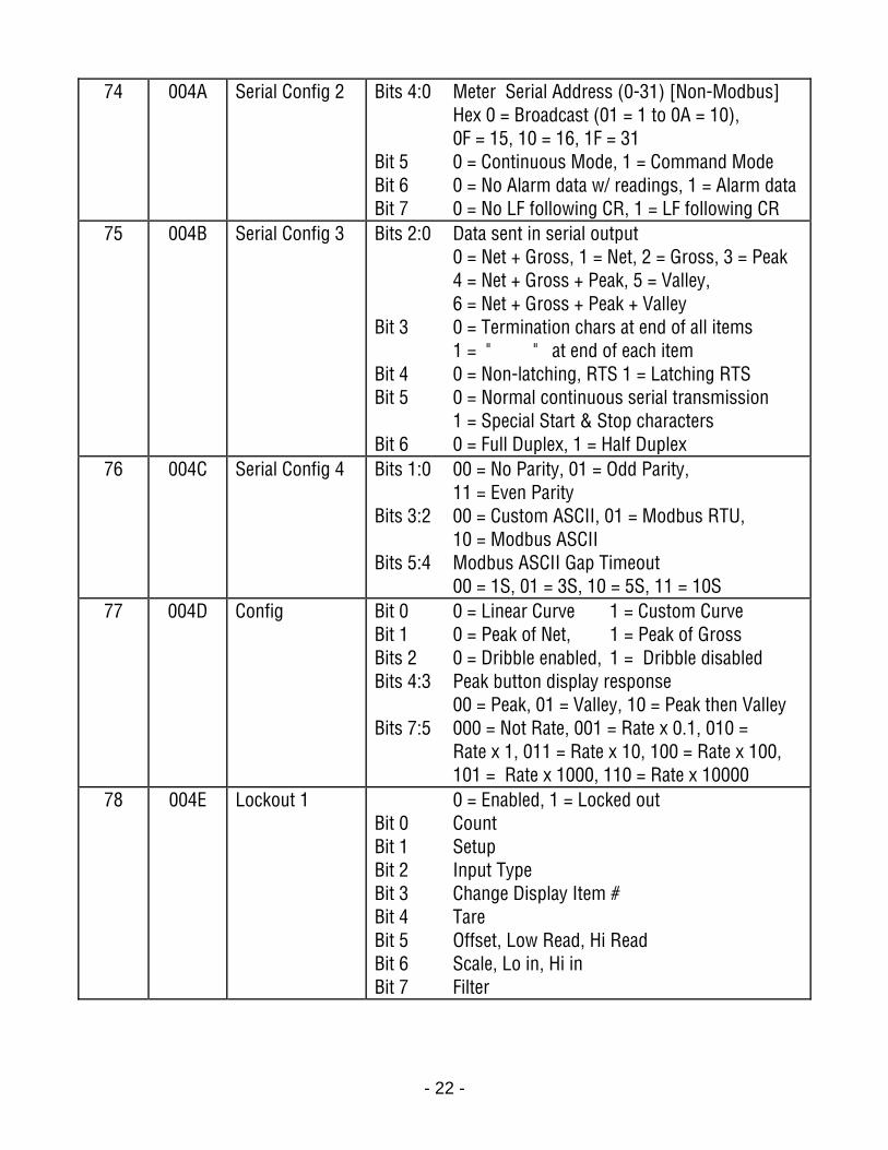
74 004A Serial Config 2 Bits 4:0 Meter Serial Address (0-31) [Non-Modbus] Hex 0 = Broadcast (01 = 1 to 0A = 10), 0F = 15, 10 = 16, 1F = 31 Bit 5 0 = Continuous Mode, 1 = Command Mode Bit 6 0 = No Alarm data w/ readings, 1 = Alarm data Bit 7 0 = No LF following CR, 1 = LF following CR
75 004B Serial Config 3 Bits 2:0 Data sent in serial output 0 = Net + Gross, 1 = Net, 2 = Gross, 3 = Peak 4 = Net + Gross + Peak, 5 = Valley, 6 = Net + Gross + Peak + Valley Bit 3 0 = Termination chars at end of all items 1 = " " at end of each item Bit 4 0 = Non-latching, RTS 1 = Latching RTS Bit 5 0 = Normal continuous serial transmission 1 = Special Start & Stop characters Bit 6 0 = Full Duplex, 1 = Half Duplex
76 004C Serial Config 4 Bits 1:0 00 = No Parity, 01 = Odd Parity, 11 = Even Parity Bits 3:2 00 = Custom ASCII, 01 = Modbus RTU, 10 = Modbus ASCII Bits 5:4 Modbus ASCII Gap Timeout 00 = 1S, 01 = 3S, 10 = 5S, 11 = 10S
77 004D Config Bit 0 0 = Linear Curve 1 = Custom Curve Bit 1 0 = Peak of Net, 1 = Peak of Gross Bits 2 0 = Dribble enabled, 1 = Dribble disabled Bits 4:3 Peak button display response 00 = Peak, 01 = Valley, 10 = Peak then Valley Bits 7:5 000 = Not Rate, 001 = Rate x 0.1, 010 = Rate x 1, 011 = Rate x 10, 100 = Rate x 100, 101 = Rate x 1000, 110 = Rate x 10000
78 004E Lockout 1 0 = Enabled, 1 = Locked out Bit 0 Count Bit 1 Setup Bit 2 Input Type Bit 3 Change Display Item # Bit 4 Tare Bit 5 Offset, Low Read, Hi Read Bit 6 Scale, Lo in, Hi in Bit 7 Filter
- 23 -
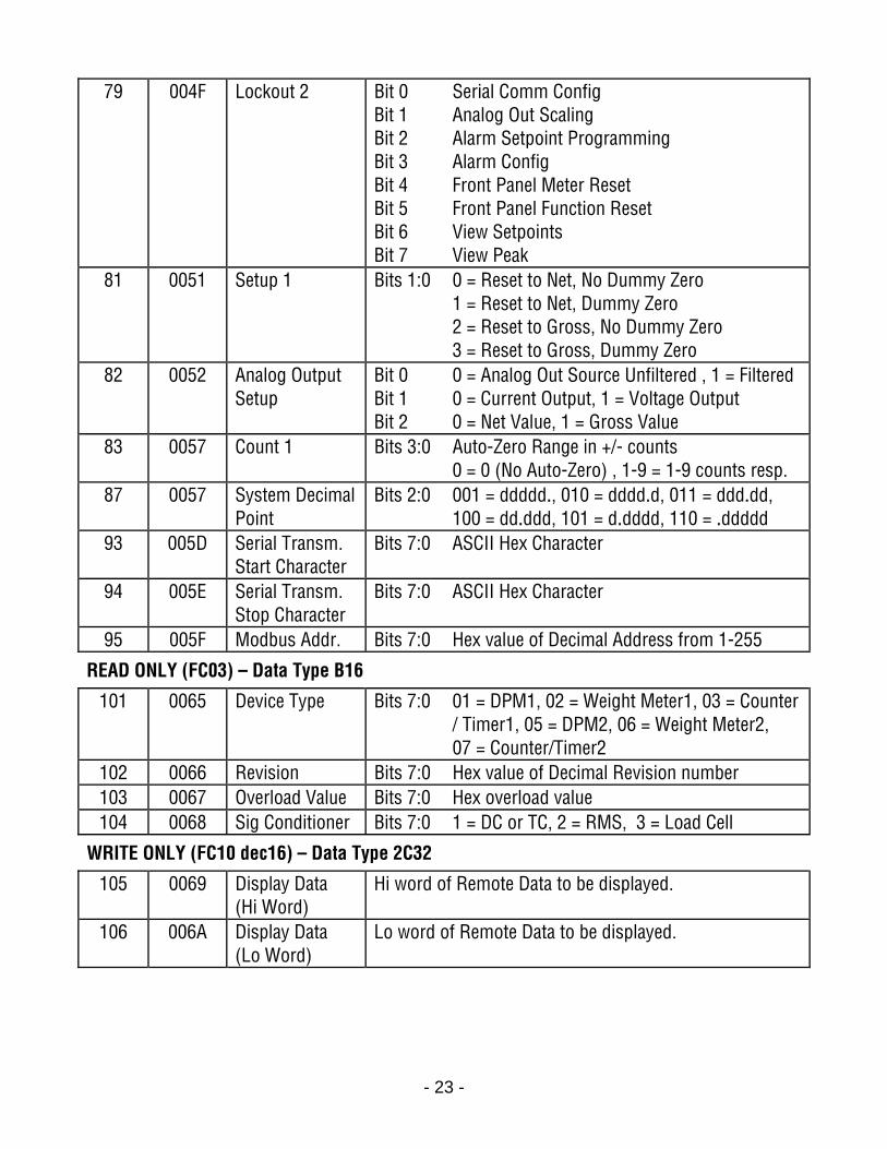
79 004F Lockout 2 Bit 0 Serial Comm Config Bit 1 Analog Out Scaling Bit 2 Alarm Setpoint Programming Bit 3 Alarm Config Bit 4 Front Panel Meter Reset Bit 5 Front Panel Function Reset Bit 6 View Setpoints Bit 7 View Peak
81 0051 Setup 1 Bits 1:0 0 = Reset to Net, No Dummy Zero 1 = Reset to Net, Dummy Zero 2 = Reset to Gross, No Dummy Zero 3 = Reset to Gross, Dummy Zero
82 0052 Analog Output Setup
Bit 0 0 = Analog Out Source Unfiltered , 1 = Filtered Bit 1 0 = Current Output, 1 = Voltage Output Bit 2 0 = Net Value, 1 = Gross Value
83 0057 Count 1 Bits 3:0 Auto-Zero Range in +/- counts 0 = 0 (No Auto-Zero) , 1-9 = 1-9 counts resp.
87 0057 System Decimal Point
Bits 2:0 001 = ddddd., 010 = dddd.d, 011 = ddd.dd, 100 = dd.ddd, 101 = d.dddd, 110 = .ddddd
93 005D Serial Transm. Start Character
Bits 7:0 ASCII Hex Character
94 005E Serial Transm. Stop Character
Bits 7:0 ASCII Hex Character
95 005F Modbus Addr. Bits 7:0 Hex value of Decimal Address from 1-255
READ ONLY (FC03) – Data Type B16
101 0065 Device Type Bits 7:0 01 = DPM1, 02 = Weight Meter1, 03 = Counter / Timer1, 05 = DPM2, 06 = Weight Meter2, 07 = Counter/Timer2
102 0066 Revision Bits 7:0 Hex value of Decimal Revision number 103 0067 Overload Value Bits 7:0 Hex overload value 104 0068 Sig Conditioner Bits 7:0 1 = DC or TC, 2 = RMS, 3 = Load Cell
WRITE ONLY (FC10 dec16) – Data Type 2C32
105 0069 Display Data (Hi Word)
Hi word of Remote Data to be displayed.
106 006A Display Data (Lo Word)
Lo word of Remote Data to be displayed.
- 24 -
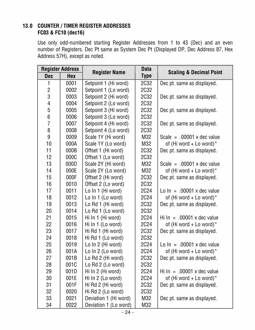
13.0 COUNTER / TIMER REGISTER ADDRESSES FC03 & FC10 (dec16)
Use only odd-numbered starting Register Addresses from 1 to 43 (Dec) and an even number of Registers. Dec Pt same as System Dec Pt (Displayed DP, Dec Address 87, Hex Address 57H), except as noted.
Register Address
Dec Hex Register Name Data
Type Scaling & Decimal Point
1 2 3 4 5 6 7 8 9 10 11 12 13 14 15 16 17 18 19 20 21 22 23 24 25 26 27 28 29 30 31 32 33 34
0001 0002 0003 0004 0005 0006 0007 0008 0009 000A 000B 000C 000D 000E 000F 0010 0011 0012 0013 0014 0015 0016 0017 0018 0019 001A 001B 001C 001D 001E 001F 0020 0021 0022
Setpoint 1 (Hi word) Setpoint 1 (Lo word) Setpoint 2 (Hi word) Setpoint 2 (Lo word) Setpoint 3 (Hi word) Setpoint 3 (Lo word) Setpoint 4 (Hi word) Setpoint 4 (Lo word) Scale 1Y (Hi word) Scale 1Y (Lo word) Offset 1 (Hi word) Offset 1 (Lo word) Scale 2Y (Hi word) Scale 2Y (Lo word) Offset 2 (Hi word) Offset 2 (Lo word) Lo In 1 (Hi word) Lo In 1 (Lo word) Lo Rd 1 (Hi word) Lo Rd 1 (Lo word) Hi In 1 (Hi word) Hi In 1 (Lo word) Hi Rd 1 (Hi word) Hi Rd 1 (Lo word) Lo In 2 (Hi word) Lo In 2 (Lo word) Lo Rd 2 (Hi word) Lo Rd 2 (Lo word) Hi In 2 (Hi word) Hi In 2 (Lo word) Hi Rd 2 (Hi word) Hi Rd 2 (Lo word) Deviation 1 (Hi word) Deviation 1 (Lo word)
2C32 2C32 2C32 2C32 2C32 2C32 2C32 2C32 M32 M32 2C32 2C32 M32 M32 2C32 2C32 2C24 2C24 2C32 2C32 2C24 2C24 2C32 2C32 2C24 2C24 2C32 2C32 2C24 2C24 2C32 2C32 M32 M32
Dec pt. same as displayed. Dec pt. same as displayed. Dec pt. same as displayed. Dec pt. same as displayed. Scale = .00001 x dec value of (Hi word + Lo word)* Dec pt. same as displayed. Scale = .00001 x dec value of (Hi word + Lo word)* Dec pt. same as displayed. Lo In = .00001 x dec value of (Hi word + Lo word)* Dec pt. same as displayed. Hi In = .00001 x dec value of (Hi word + Lo word)* Dec pt. same as displayed. Lo In = .00001 x dec value of (Hi word + Lo word)* Dec pt. same as displayed. Hi In = .00001 x dec value of (Hi word + Lo word)* Dec pt. same as displayed. Dec pt. same as displayed.
- 25 -
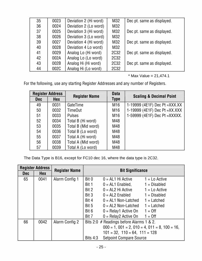
35 36 37 38 39 40 41 42 43 44
0023 0024 0025 0026 0027 0028 0029 002A 002B 002C
Deviation 2 (Hi word) Deviation 2 (Lo word) Deviation 3 (Hi word) Deviation 3 (Lo word) Deviation 4 (Hi word) Deviation 4 Lo word) Analog Lo (Hi word) Analog Lo (Lo word) Analog Hi (Hi word) Analog Hi (Lo word)
M32 M32 M32 M32 M32 M32 2C32 2C32 2C32 2C32
Dec pt. same as displayed. Dec pt. same as displayed. Dec pt. same as displayed. Dec pt. same as displayed. Dec pt. same as displayed.
* Max Value = 21,474.1
For the following, use any starting Register Addresses and any number of Registers.
Register Address Dec Hex
Register Name Data Type
Scaling & Decimal Point
49 50 51 52 53 54 55 56 57
0031 0032 0033 0034 0035 0036 0037 0038 0039
GateTime TimeOut Pulses Total B (Hi word) Total B (Mid word) Total B (Lo word) Total A (Hi word) Total A (Mid word) Total A (Lo word)
M16 M16 M16 M48 M48 M48 M48 M48 M48
1-19999 (4E1F) Dec Pt =XXX.XX 1-19999 (4E1F) Dec Pt =XX.XXX 1-59999 (4E1F) Dec Pt =XXXXX.
The Data Type is B16, except for FC10 dec 16, where the data type is 2C32.
Register Address Dec Hex
Register Name Bit Significance
65
0041 Alarm Config 1 Bit 0 0 = AL1 Hi Active 1 = Lo Active Bit 1 0 = AL1 Enabled, 1 = Disabled Bit 2 0 = AL2 Hi Active 1 = Lo Active Bit 3 0 = AL2 Enabled 1 = Disabled Bit 4 0 = AL1 Non-Latched 1 = Latched Bit 5 0 = AL2 Non-Latched 1 = Latched Bit 6 0 = Relay1 Active On 1 = Off Bit 7 0 = Relay2 Active On 1 = Off
66 0042 Alarm Config 2 Bits 2:0 # Readings before Alarms 1 & 2. 000 = 1, 001 = 2, 010 = 4, 011 = 8, 100 = 16, 101 = 32, 110 = 64, 111 = 128 Bits 4:3 Setpoint Compare Source

- 26 -
Bit 3 AL1 0 = Deviation 1 = Hysteresis Bit 4 AL2 0 = Deviation 1 = Hysteresis Bit 5 0 = Deviation in Menu 1 = Omitted
67 0043 Alarm Config 3 (Alarms 3 & 4 are planned developments)
Bit 0 0 = AL3 Hi Active 1 = Lo Active Bit 1 0 = AL3 Enabled 1 = Disabled Bit 2 0 = AL4 Hi Active 1 = Lo Active Bit 3 0 = AL4 Enabled 1 = Disabled Bit 4 0 = AL3 Non-Latched 1 = Latched Bit 5 0 = AL4 Non-Latched 1 = Latched Bit 6 0 = Relay3 Active On 1 = Off Bit 7 0 = Relay4 Active On 1 = Off
68 0044 Alarm Config 4 (Alarms 3 & 4 are planned developments)
Bits 2:0 = # Readings before Alarms 3 & 4. 000 = 1, 001 = 2, 010 = 4, 011 = 8, 100 = 16, 101 = 32 110 = 64 111 = 128 Bit 3 AL3 0 = Deviation 1 = Hysteresis Bit 4 AL4 0 = Deviation 1 = Hysteresis Bit 5 0 = Deviation in Menu 1 = Omitted
69 0045 Input Type 00-0F 00 = Rate A&B, 01 = AOnly, 02 = Batch, 03 = A_Atot, 05 = A_Btot, 0B = A+B, 0C = A-B, 0D = A*B, 0E = A/B, 0F = A/B-1 10-11 10 = Period A&B, 11 = AOnly 1B-1E 1B = A+B, 1C = A-B, 1D = A*B, 1E = A/B 20-21 20 = Total A&B, 21 = AOnly 24-2E 24 = A-B_ud, 26 = Burst=26, 27 = B_Arat, 29 = A_Bud, 2A = A_Binh, 2B = A+B, 2C = A-B, 2D = A*B, 2E = A/B 41 41 = Time Interval A to B 50-51 50 = Stopwatch A to A, 51 = Stopwatch A to B 61-62 61 = Phase 0-360 62 = Phase -180 to +180 71 71 = Duty Cycle A to B XY V-to F Signal Conditioner if X = 8, 9 or A 81 = V-to-F, 4-20 mA input, Aonly 82 = V-to-F, 4-20 mA in, Batch 83 = V-to-F, 4-20 mA in, A_Atot 8F = V-to-F, 4-20 mA in, 1/A 91 = V-to-F, 0-1 mA in, Aonly 92 = V-to-F, 0-1 mA in, Batch 93 = V-to-F, 0-1 mA in, A_Atot 9F = V-to-F, 0-1 mA in, 1/A A1 = V-to-F, 0-10V in, Aonly

- 27 -
A2 = V-to-F, 0-10V in, Batch A3 = V-to-F, 0-10V in, A_Atot AF = V-to-F, 0-10V in, 1/A C0-C1 C0 = Quadrature Total C1 = Quadrature Rate=C1
70 0046 Setup Bits 3:0 Ctrl In 1 Ctrl In 2 Both Reset Hex 0 MReset FReset Cold (M = Meter) Hex 1 MReset MHold Cold (F = Function) Hex 2 MReset Pk, Vy Cold (D = Display) Hex 3 MReset ExtGate Cold Hex 4 FReset MHold Func Hex 5 Valley Peak Func Hex 6 FReset ExtGate Cold Hex 7 MHold Pk, Vy Func Hex 8 MHold ExtGate Cold Hex 9 Pk, Vy ExtGate NoAction Hex A MReset DBlank Cold Hex B FReset DBlank Cold Hex C MHold DBlank Cold Hex D Pk, Vy DBlank Func Hex E DBlank ExtGate Cold Hex E Item2 Item3 Item 1 = Neither Bit 4 0 = Scale2 using Scale, Offset 1 =S cale2 using Coordinates of 2 Points Bit 5 0 = Scale1 using Scale, Offset 1 = Scale1 using Coordinates of 2 Points Bit 6 0 = Blank leading zeros 1 = Display leading zeros Bit 7 0 = Zero Total upon Power-On 1 = Restore Total upon Power-On
71 0047 Filter Bits 2:0 1= .1S, 2 = .2S, 3 = .4S, 4=.8S, 5=1.6S, 6 = 3.2S, 7=6.4S Bit 3 0 = Low Adaptive, 1 =High Adaptive Bit 4 0 = Display Unfiltered, 1=Display Filtered Bit 5 0 = Peak, Valley of Unfiltered 1 = Peak,Valley of Filtered Bit 6 0 = Adaptive Filter, 1 = Conventional Filter
72 0048 Options Do Not Use. Serial Config 1,2,3 do not pertain to Modbus parameters, only Serial Config 4.
73 0049 Serial Config 1 Bits 3:0 Time between Continuous Serial Outputs Hex 0=.017S, 1=.28S, 2=.57S, 3=1.1S, 4=2.3S, 5=4.5S, 6=9.1S, 7=18.1S, 8=36.3S, 9=1M13S,
- 28 -
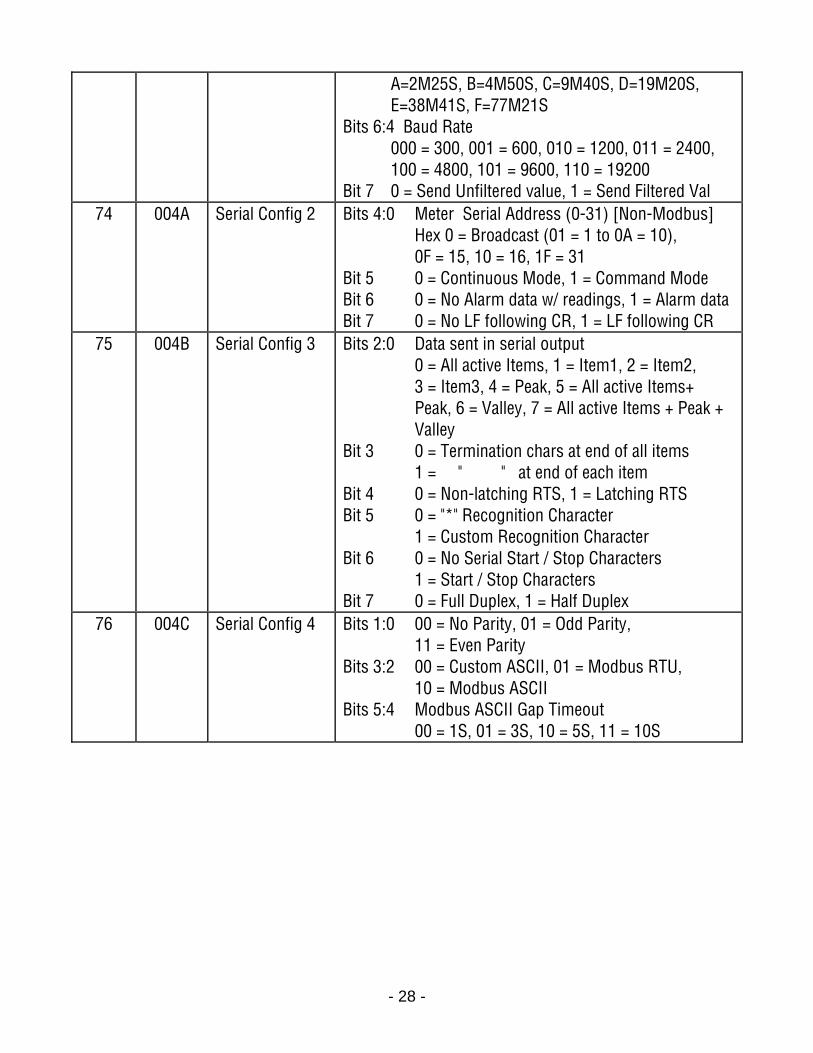
A=2M25S, B=4M50S, C=9M40S, D=19M20S, E=38M41S, F=77M21S Bits 6:4 Baud Rate 000 = 300, 001 = 600, 010 = 1200, 011 = 2400, 100 = 4800, 101 = 9600, 110 = 19200 Bit 7 0 = Send Unfiltered value, 1 = Send Filtered Val
74 004A Serial Config 2 Bits 4:0 Meter Serial Address (0-31) [Non-Modbus] Hex 0 = Broadcast (01 = 1 to 0A = 10), 0F = 15, 10 = 16, 1F = 31 Bit 5 0 = Continuous Mode, 1 = Command Mode Bit 6 0 = No Alarm data w/ readings, 1 = Alarm data Bit 7 0 = No LF following CR, 1 = LF following CR
75 004B Serial Config 3 Bits 2:0 Data sent in serial output 0 = All active Items, 1 = Item1, 2 = Item2, 3 = Item3, 4 = Peak, 5 = All active Items+ Peak, 6 = Valley, 7 = All active Items + Peak + Valley Bit 3 0 = Termination chars at end of all items 1 = " " at end of each item Bit 4 0 = Non-latching RTS, 1 = Latching RTS Bit 5 0 = "*" Recognition Character 1 = Custom Recognition Character Bit 6 0 = No Serial Start / Stop Characters 1 = Start / Stop Characters Bit 7 0 = Full Duplex, 1 = Half Duplex
76 004C Serial Config 4 Bits 1:0 00 = No Parity, 01 = Odd Parity, 11 = Even Parity Bits 3:2 00 = Custom ASCII, 01 = Modbus RTU, 10 = Modbus ASCII Bits 5:4 Modbus ASCII Gap Timeout 00 = 1S, 01 = 3S, 10 = 5S, 11 = 10S
- 29 -
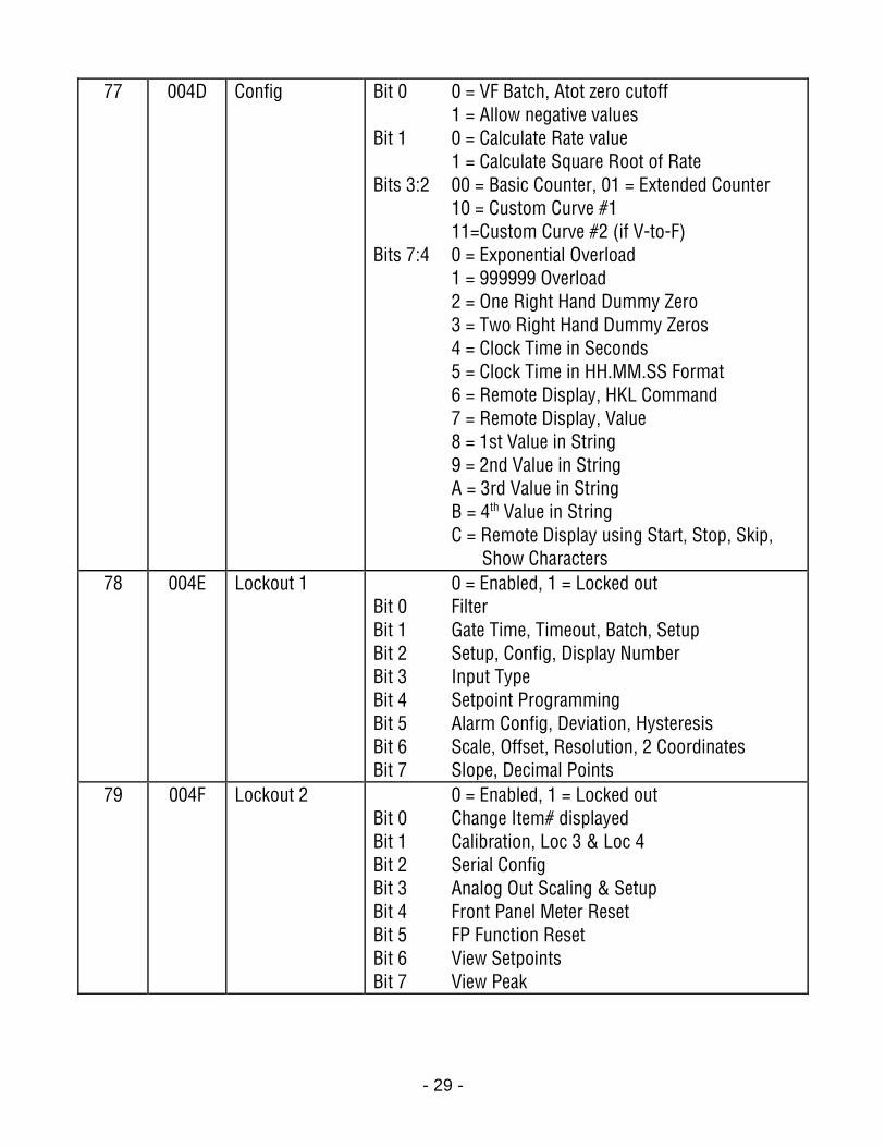
77 004D Config Bit 0 0 = VF Batch, Atot zero cutoff 1 = Allow negative values Bit 1 0 = Calculate Rate value 1 = Calculate Square Root of Rate Bits 3:2 00 = Basic Counter, 01 = Extended Counter 10 = Custom Curve #1 11=Custom Curve #2 (if V-to-F) Bits 7:4 0 = Exponential Overload 1 = 999999 Overload 2 = One Right Hand Dummy Zero 3 = Two Right Hand Dummy Zeros 4 = Clock Time in Seconds 5 = Clock Time in HH.MM.SS Format 6 = Remote Display, HKL Command 7 = Remote Display, Value 8 = 1st Value in String 9 = 2nd Value in String A = 3rd Value in String B = 4th Value in String C = Remote Display using Start, Stop, Skip, Show Characters
78 004E Lockout 1 0 = Enabled, 1 = Locked out Bit 0 Filter Bit 1 Gate Time, Timeout, Batch, Setup Bit 2 Setup, Config, Display Number Bit 3 Input Type Bit 4 Setpoint Programming Bit 5 Alarm Config, Deviation, Hysteresis Bit 6 Scale, Offset, Resolution, 2 Coordinates Bit 7 Slope, Decimal Points
79 004F Lockout 2 0 = Enabled, 1 = Locked out Bit 0 Change Item# displayed Bit 1 Calibration, Loc 3 & Loc 4 Bit 2 Serial Config Bit 3 Analog Out Scaling & Setup Bit 4 Front Panel Meter Reset Bit 5 FP Function Reset Bit 6 View Setpoints Bit 7 View Peak
- 30 -
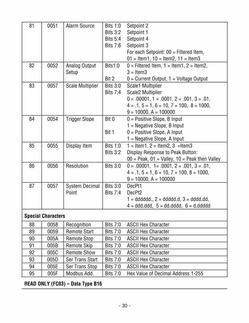
81 0051 Alarm Source Bits 1:0 Setpoint 2 Bits 3:2 Setpoint 1 Bits 5:4 Setpoint 4 Bits 7:6 Setpoint 3 For each Setpoint: 00 = Filtered Item, 01 = Item1, 10 = Item2, 11 = Item3
82 0052 Analog Output Setup
Bits1:0 0 = Filtered Item, 1 = Item1, 2 = Item2, 3 = Item3 Bit 2 0 = Current Output, 1 = Voltage Output
83 0057 Scale Multiplier Bits 3:0 Scale1 Multiplier Bits 7:4 Scale2 Multiplier 0 = .00001, 1 = .0001, 2 = .001, 3 = .01, 4 = .1, 5 = 1, 6 = 10, 7 = 100, 8 = 1000, 9 = 10000, A = 100000
84 0054 Trigger Slope Bit 0 0 = Positive Slope, B Input 1 = Negative Slope, B Input Bit 1 0 = Positive Slope, A Input 1 = Negative Slope, A Input
85 0055 Display Item Bits 1:0 1 = Item1, 2 = Item2, 3 =Item3 Bits 3:2 Display Response to Peak Button: 00 = Peak, 01 = Valley, 10 = Peak then Valley
86 0056 Resolution Bits 3:0 0 = .00001, 1= .0001, 2 = .001, 3 = .01, 4 = .1, 5 = 1, 6 = 10, 7 = 100, 8 = 1000, 9 = 10000, A = 100000
87 0057 System Decimal Point
Bits 3:0 DecPt1 Bits 7:4 DecPt2 1 = dddddd., 2 = ddddd.d, 3 = dddd.dd, 4 = ddd.ddd, 5 = dd.dddd, 6 = d.ddddd
Special Characters
88 0058 Recognition Bits 7:0 ASCII Hex Character 89 0059 Remote Start Bits 7:0 ASCII Hex Character 90 005A Remote Stop Bits 7:0 ASCII Hex Character 91 005B Remote Skip Bits 7:0 ASCII Hex Character 92 005C Remote Show Bits 7:0 ASCII Hex Character 93 005D Ser Trans Start Bits 7:0 ASCII Hex Character 94 005E Ser Trans Stop Bits 7:0 ASCII Hex Character 95 005F Modbus Add. Bits 7:0 Hex Value of Decimal Address 1-255
READ ONLY (FC03) – Data Type B16
- 31 -
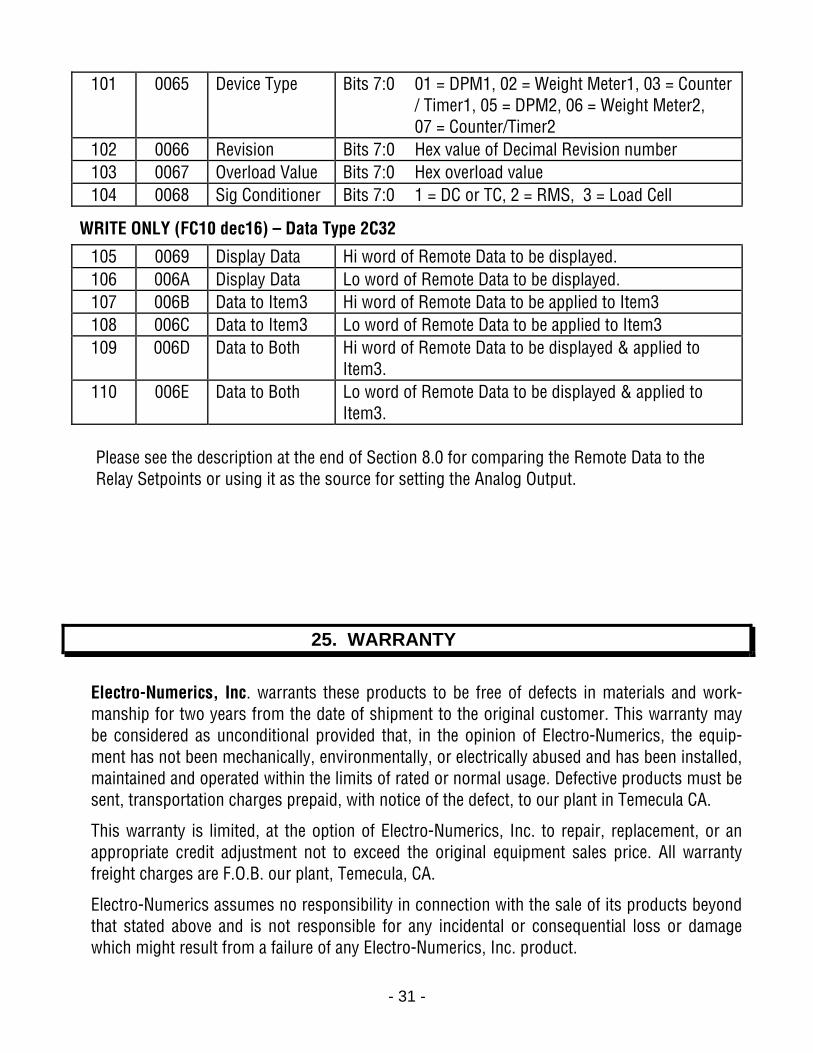
101 0065 Device Type Bits 7:0 01 = DPM1, 02 = Weight Meter1, 03 = Counter / Timer1, 05 = DPM2, 06 = Weight Meter2, 07 = Counter/Timer2
102 0066 Revision Bits 7:0 Hex value of Decimal Revision number 103 0067 Overload Value Bits 7:0 Hex overload value 104 0068 Sig Conditioner Bits 7:0 1 = DC or TC, 2 = RMS, 3 = Load Cell
WRITE ONLY (FC10 dec16) – Data Type 2C32
105 0069 Display Data Hi word of Remote Data to be displayed. 106 006A Display Data Lo word of Remote Data to be displayed. 107 006B Data to Item3 Hi word of Remote Data to be applied to Item3 108 006C Data to Item3 Lo word of Remote Data to be applied to Item3 109 006D Data to Both Hi word of Remote Data to be displayed & applied to
Item3. 110 006E Data to Both Lo word of Remote Data to be displayed & applied to
Item3. Please see the description at the end of Section 8.0 for comparing the Remote Data to the Relay Setpoints or using it as the source for setting the Analog Output.
25. WARRANTY
Electro-Numerics, Inc. warrants these products to be free of defects in materials and work-manship for two years from the date of shipment to the original customer. This warranty may be considered as unconditional provided that, in the opinion of Electro-Numerics, the equip-ment has not been mechanically, environmentally, or electrically abused and has been installed, maintained and operated within the limits of rated or normal usage. Defective products must be sent, transportation charges prepaid, with notice of the defect, to our plant in Temecula CA.
This warranty is limited, at the option of Electro-Numerics, Inc. to repair, replacement, or an appropriate credit adjustment not to exceed the original equipment sales price. All warranty freight charges are F.O.B. our plant, Temecula, CA.
Electro-Numerics assumes no responsibility in connection with the sale of its products beyond that stated above and is not responsible for any incidental or consequential loss or damage which might result from a failure of any Electro-Numerics, Inc. product.

- 32 -
Copyright 2007 Electro-Numerics, Inc. REV-01 07/07