modbus plus driver - kepware · modbusplusdriver tableofcontents tableofcontents 2 modbusplusdriver...
TRANSCRIPT

Modbus Plus Driver
©2015 Kepware, Inc.

Modbus Plus Driver
Table of ContentsTable of Contents 2
Modbus Plus Driver 4
Overview 4
External Dependencies 4
Device Setup 5
Device ID (PLC Network Address) 5
Block Sizes 9
Settings 9
Variable Import Settings 12
Automatic Tag Database Generation 13
Exporting Variables from Concept 13
Exporting Variables from ProWORX 15
Exporting Variables from Unity Pro XL 16
Optimizing Modbus Plus Communications 19
Data Types Description 22
Address Descriptions 23
Modbus Addressing 23
Function Codes Description 25
Configuring the Device for Global Data Communications 25
TIOModule Addressing 26
Error Descriptions 28
Address <address> is out of range for the specified device or register. 29
Array size is out of range for address <address>. 29
Array support is not available for the specified address: <address>. 29
Data Type <type> is not valid for device address <address>. 29
Device address <address> contains a syntax error. 29
Device address <address> is read only. 29
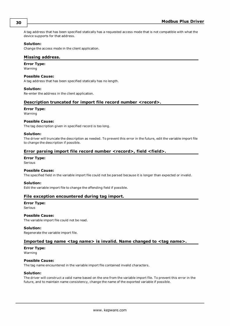
Missing address. 30
Description truncated for import file record number <record>. 30
Error parsing import file record number <record>, field <field>. 30
File exception encountered during tag import. 30
Imported tag name <tag name> is invalid. Name changed to <tag name>. 30
Tag <tag name> could not be imported because data type <data type> is not supported. 31
Tag import failed due to low memory resources. 31
Address block error <address> -<address> responded with exception 132. 31
Bad address in block [<start address> to <end address>] on device <device name>. 31
Bad array spanning [<address> to <address>] on device <device name>. 31
Block address [<start address> to <end address> ] on device <device name> responded withexception <exception code>. 32
Error opening MBPLUS path: <ID>. 32
Unable to communicate with MBPLUS.VXD. 32
Unable to open MBPLUS slave path. 32
www. kepware.com
2
Modbus Plus Driver
Unable to read from address <address> on device <device>. Device responded with exception code<code>. 33
Unable to read from address <array address> on device <device>, board responded with exceptioncode <code>. 33
Unable to start MBPLUS.SYS device. 33
Unable to write to address <address> on device <device>: Device responded with exception code<code>. 34
Unable to write to address <array address> on device <device>, board responded with exception code<code>. 34
Device <device name> is not responding. 34
Started MBPLUS.SYS device. 35
Unable to write to <address> on device <device name>. 35
Modbus Exception Codes 36
Hilscher CIF Exception Codes 37
Index 38
www. kepware.com
3

Modbus Plus Driver
Modbus Plus DriverHelp version 1.035
CONTENTS
OverviewWhat is the Modbus Plus Driver?
Device SetupHow do I configure a device for use with this driver?
Automatic Tag Database GenerationHow can I easily configure tags for the Modbus Plus Driver?
Optimizing Modbus Plus CommunicationsHow do I get the best performance from the driver?
Data Types DescriptionWhat data types does the Modbus Plus Driver support?
Address DescriptionsHow do I address a data location on a Modbus Plus device?
Error DescriptionsWhat error messages does the Modbus Plus Driver produce?
OverviewThe Modbus Plus Driver provides a reliable way to connect Modbus Plus devices to OPC Client applications,including HMI, SCADA, Historian, MES, ERP, and countless custom applications. It is intended for use with aModicon SA85, Schneider PCI-85, or Hilscher CIF 50-MBP interface card. This driver does not supportconfigurations where SA85/PCI-85 and Hilscher CIF cards exist in the same computer.
External DependenciesThis driver has external dependencies.
l An SA85 or PCI-85 interface adapter and its device driver software (MBPLUS or MBX drivers) are requiredto communicate to the Modbus Plus network. The interface adapter and device drivers can be purchasedfrom Modicon/Schneider. The OPC server can support up to eight (8) channels per SA85 or PCI-85 card.
l For configurations using the Hilscher CIF Card, the Modbus Plus Driver requires that Hilscher's SyConconfiguration software be installed on the samemachine as the card. The card may be configured anddownloaded through SyCon. The Hilscher CIF card supports one channel per adapter.
www. kepware.com
4
Modbus Plus Driver
Device SetupFor this driver, the terms Slave and Unsolicited are used interchangeably.
Supported Interface CardsSA85 CardHilscher CIF Card
Note: Users may also connect to a Modbus Plus network from a Modbus RTU Serial machine via a USB adapter.
Important: For more information on the SA85 Card and Hilscher CIF Card requirements, refer to ExternalDependencies.
Supported Communication ModesThe Modbus Plus Driver supports three communication modes, which are used to obtain data from the device.The mode is specified through the Device ID format. Options include Solicited, Unsolicited, andMailbox. Descriptions of the modes are as follows:
l Solicited: In this mode, the driver will generate read and/or write requests to the device for data.Available addresses include output coils, input coils, internal registers, and holding registers. Outputcoils and holding register addresses have Read/Write access, whereas input coils and internal registershave Read Only access. The Device ID format for Solicited Mode is DM.r1.r2.r3.r4.r5 or S.r1.r2.r3.r4.r5.
l Unsolicited: In this mode, the driver will act as a virtual PLC on the network. Reads and writes will notoriginate from the driver. Any client application that reads or writes from an unsolicited device will bepassing data to a local cache that is allocated for the device, not to the physical device. This local cache islocated in the PC that is running the driver. Devices on the network read and write to the same cachethrough unsolicited commands. The Device ID format for Unsolicited Mode is DS.r1.r2.r3.r4.r5.
l Mailbox: In this mode, the driver will act as a storage area for every defined mailbox device. When anunsolicited command is received, the driver will detect the routing path from which the message came,and then place the data in the storage area allocated for that device. If the message comes from a devicewith a routing path that has not been defined as a mailbox device, the message will not be processed. Anyclient application that reads from amailbox device will read from the storage area contained in the driverinstead of the physical device; however, writes will be sent to the physical device as well as the localcache. Only holding registers are supported in this mode. The Double data type is not supported. TheDevice ID format for Mailbox Mode is U.r1.r2.r3.r4.r5.
Note: Unsolicited mailbox commands are made possible by the MSTR instruction available in certainModicon devices. For more information, refer to "Example 2 - Mailbox Mode Single Network" and "Example3 - Mailbox Mode Bridged Network" in Device ID.
For information on the communication modes that are supported by the SA85 and Hilscher CIF interface cards,refer to the table below.
Mode SA85 Card Hilscher CIF CardSolicited x xUnsolicited xMailbox x
Note: For more information, refer toDevice ID.
Polling Multiple DevicesThe Modbus Plus Driver can poll multiple devices on an Modbus Plus network, and can also act as a single slavedevice on the Modbus Plus network for other devices to poll. The driver is limited to 8192 devices and supportsup to 4 adapters.
Device ID (PLC Network Address)The Device ID specifies the path to a node on the network. It consists of five consecutive routing bytes in additionto a mode designator. The mode may be Master, Slave, or Mailbox.
Important: For this driver, the terms Slave and Unsolicited are used interchangeably.
Solicited Mode (Data Master)Data Master paths start with the prefix DM or S and are used to communicate with another node on the network.The Host PC acts as the master in conversations of this type. A DM path can identify a PLC or any other devices
www. kepware.com
5

Modbus Plus Driver
that can respond to Modbus Read and Write commands, including another Host PC running the Modbus PlusDriver. The format of a DM path is DM.r1.r2.r3.r4.r5 or S.r1.r2.r3.r4.r5.
Unsolicited Mode (Data Slave)A single Data Slave path can be configured per SA85 card and has the format DS.1.0.0.0.0. By defining a slavepath, users enable the Host PC running the Modbus Plus Driver to simulate a PLC device on the network capable ofresponding to Read/Write requests from other devices. Other devices can communicate with this simulateddevice by opening a Data Master path to it.
The simulated PLC device uses Modbus byte ordering: first word is low word of DWord for 32-bit and 64-bitvalues and first DWord is low DWord for 64-bit values for Data Encoding. Therefore, the Data Encoding optionsfor the unsolicited device must be set to the following:
l Modbus Byte Order.l First Word Low in 32 Bit Data Types.l First DWord Low in 64 Bit Data Types.
Note: For more information, refer to Settings.
Addresses 1 to 65536 are implemented for output coils, input coils, internal registers and holding registers. Thedriver will respond to any valid request to read or write these values from external devices (Function Codes[decimal] 01, 02, 03, 04, 05, 06, 15, 16). These locations can also be accessed locally by the Host PC as tagsassigned to the slave device. Write Only access is not allowed for an unsolicited device.
When a Slave path is enabled, the Modbus Plus Driver will enable eight slave paths on each SA85 card. Thisallows the remote PLCs and other Modbus Plus devices to access the slave memory of this driver using any of theeight slave paths. The memory accessed is the same in all cases. In terms of an MSTR instruction, users canspecify a path of 1 through 8 when defining what path to connect with on the SA85 card serviced by this driver.This can be useful if the application has a large number of remote devices that will be sending data to the PC. Ifthis is the case, users can utilize the eight slave paths to distribute the load from remote nodes. Each slave pathin this driver has its own thread of execution to ensure the highest level of performance.
If no slave device is defined in the project, the driver will ignore any unsolicited read or write requests it receives.
Note: Unsolicited mode is not supported with Hilscher CIF cards.
Mailbox ModeA Mailbox path starts with the prefix U and provides a path to a physical device. A storage area will be providedfor this physical device in the slave device defined in the project. Although the physical device sends unsolicitedwrites to this storage area, they can also be accessed locally by the Host PC as tags assigned to the slave device.The format of a mailbox path is U.r1.r2.r3.r4.r5.
The driver always opens a slave path when receiving unsolicited mailbox data. The path the driver opens isDS.1.0.0.0.0. Devices on the same Modbus Plus network communicate with the driver by opening the DataMaster path DM.<local node> .1.0.0.0, where the local node is the address set on the SA85 card of the HostComputer. For a description of the path devices on a bridged network use, refer to Example 3.
Devices use the Modbus Plus MSTR instruction to provide data to the driver. In order for the driver to be able toassociate the data with a particular device, the Device ID path must be embedded in the first five registers of thereceived data. If the first five registers of data do not match the Device ID path of the device in the project, thereceived data will be discarded. Only the Write command is supported for the MSTR instruction.
Notes:
1. Mailbox Mode is not supported with Hilscher CIF cards.
2. The Device ID path is embedded in the path from the Host PC to the device, not the device path to the HostPC.
3. A TIO Module device does not support a slave network address.
4. The Device ID should not be changed while clients are connected. If it is, the change will not take effectuntil all clients are disconnected and then reconnected.
Example 1 - Solicited Mode
www. kepware.com
6

Modbus Plus Driver
A single network consists of four nodes, such that nodes 1 and 4 are Host PCs running software that uses theModbus Plus Driver. Nodes 2 and 3 are PLCs. The following table displays the addressing for the network as fromeach node.
From To Node 1 To Node 2 To Node 3 To Node 4Node 1 --------------- DM.2.0.0.0.0 DM.3.0.0.0.0 DM.4.1.0.0.0Node 2 DM.1.1.0.0.0 --------------- DM.3.0.0.0.0 DM.4.1.0.0.0Node 3 DM.1.1.0.0.0 DM.2.0.0.0.0 --------------- DM.4.1.0.0.0Node 4 DM.1.1.0.0.0 DM.2.0.0.0.0 DM.3.0.0.0.0 ---------------
Note: In order to access the simulated device on a Host PC, the last non-zero number in the path is always one.This indicates the slave path used by the driver.
Example 2 - Mailbox Mode Single NetworkTransferring registers 40020 to 40029 from the device to locations 40001 to 40010 of the Host PC. The locationof the control block can be different. The Host PC address is 7.0.0.0.0. The device address is 3.0.0.0.0.
MSTR InstructionControl block 40001 -Data area 40015 Start five registers early.Length 15 Five more than the actual data.
Control BlockRegister Contents Description40001 1 Write operation.40002 0 Holds error code.40003 15 Number of registers to transfer.40004 1 Starting location in the Host PC (Register 40001).40005 7 Path to Host PC.40006 1 Path to Host PC.40007 0 Path to Host PC.40008 0 Path to Host PC.40009 0 Path to Host PC.
Data AreaRegister Contents Description40015 3 Path back to device from Host PC, the Device ID.40016 0 Path back to device from Host PC.40017 0 Path back to device from Host PC.40018 0 Path back to device from Host PC.40019 0 Path back to device from Host PC.40020 - Actual data start.40029 - Actual data end.
Upon receiving an unsolicited message, the driver will do the following:
1. If the message is understood, the driver will send an acknowledgment to the sending device. If messagesare received for functions other than Preset Multiple Registers, code 0x10, the driver will return aFunction Not Implemented response. Preset Multiple Registers is the function code devices on thereceiving end of an MSTR instruction. The driver will return an exception response if the message is notunderstood or incomplete.
2. The driver will attempt to match the first five registers of data received to the Device ID path of a device inthe project. If none is found, the data will be discarded. If the data is less than six registers, it will bediscarded immediately.
3. The driver will copy n - 5 registers of data starting at the sixth register of the received data to the imagemap maintained internally for the device (starting at the location indicated in the message). The drivermay need to allocate storage for the image map if this is the first data received for these locations.
www. kepware.com
7
Modbus Plus Driver
4. The data will be made available to the driver's clients. The data in this example would be referenced astags with addresses 40001 to 40009 of the device with Device ID U.3.0.0.0.0. The client would refer tothe device using a logical name assigned when the device was created in the project. The data could alsobe referenced as an array, such as 40001[10] or 40001[2][5].
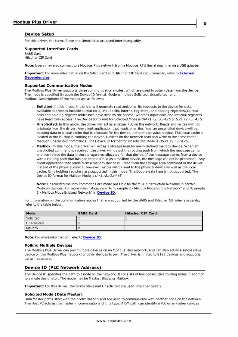
Example 3 - Mailbox Mode Bridged Network
The Host PC's address from the PLC's perspective is 4.2.9.7.1. The PLC's address from the Host PC's perspectiveis 15.23.10.18.0. This is the Device ID path. If the same registers were transferred from the PLC to the samelocations in the Host PC, the following control block and data area would be used in the MSTR instruction:
MSTR InstructionControl block 40001 -Data area 40015 Start five registers early.Length 15 Five more than the actual data.
Control BlockRegister Contents Description40001 1 Write operation.40002 0 Holds error code.40003 15 Number of registers to transfer.40004 1 Starting location in the Host PC (Register 40001).40005 4 Path to Host PC.40006 2 Path to Host PC.40007 9 Path to Host PC.40008 7 Path to Host PC.40009 1 Path to Host PC.
Data AreaRegister Contents Description40015 15 Path back to device from Host PC, the Device ID.40016 23 Path back to device from Host PC.40017 10 Path back to device from Host PC.40018 18 Path back to device from Host PC.40019 0 Path back to device from Host PC.40020 - Actual data start.40029 - Actual data end.
The message would be processed the same.
Note: When using this driver, the Host PC can be three networks apart from a device at the most.
www. kepware.com
8

Modbus Plus Driver
Block SizesCoil Block Sizes
SA85 CardCoils can be read from 8 to 2000 points (bits) at a time. The default setting is 512 coils.
Hilscher CIF CardCoils can be read from 8 to 248 points (bits) at a time. The default setting is 248 coils.
Register Block SizesSA85 CardRegisters can be read from 1 to 120 locations (words) at a time. The default setting is 120 registers.
Hilscher CIF CardRegisters can be read from 1 to 95 locations (words) at a time. The default setting is 95 registers.
Caution: If the Register Block sizes value is set above 120 and a 32 or 64-bit data type is used for any tag, thena "Bad address in block" error could occur. Decrease block size value to 120 to prevent the error from occurring.
Note: For a TIO Module, use this setting to inform the driver how many bytes will be returned when reading datalocation 400001. For modules that return 2 bytes, set this to 1. For modules that return 3 bytes, set this to 2. Thedriver uses fixed block lengths (independent from this setting) for all other data locations.
Reasons to Change the Default Block Sizes
1. The device may not support block Read/Write operations of the default size. Smaller Modicon PLCs andnon-Modicon devices may not support the maximum data transfer lengths supported by the MBPlusnetwork.
2. The device may contain non-contiguous addresses. If this is the case and the driver attempts to read ablock of data that encompasses undefined memory, the device will probably reject the request.
Perform Block Read on StringsCheck this option to block read string tags, which are normally read individually. When this option is selected,string tags will be grouped together depending on the selected block size. Block reads can only be performed forModbus model string tags.
SettingsAdapter NumberThis parameter specifies the adapter number that will be used by the Modbus Plus card. Valid adapter numbersare 0 to 3. For card-specific information, refer toDevice Setup.
TimeoutThis parameter specifies the time that the driver will wait for a response from the device before giving up andgoing on to the next request. The timeout will be rounded up to the nearest half second. Longer timeouts onlyaffect performance if a device is not responding. The driver polls the MBPlus system driver for the deviceresponse at 10 ms intervals.
----- Data Access Group -----Zero- vs. One-Based AddressingIf the address numbering convention for the device starts at one instead of zero, users can specify so whendefining the device's parameters. By default, user-entered addresses will have one subtracted when frames areconstructed to communicate with a Modbus device. If the device doesn't follow this convention, users canuncheck Use zero-based addressing in Device Properties. For information on the appropriate application fromwhich details on setting device properties may be obtained, refer to the online help. The default behavior followsthe convention of the Modicon PLCs.
Note: Hilscher CIF cards support One Based Addressing only.
Zero- vs One-Based Bit Addressing within registersMemory types that allow bits within Words can be referenced as a Boolean. The addressing notation for doing thisis as follows:
<address> .<bit>
www. kepware.com
9

Modbus Plus Driver
where <bit> represents the bit number within the Word. Zero-Based Bit Addressing within registers providestwo ways of addressing a bit within a given Word; Zero Based and One Based. Zero-Based Bit addressing withinregisters simply means the first bit begins at 0. With One Based, the first bit begins at 1.
Zero-Based Bit Addressing Within Registers (Default Setting /Checked)
Data Type Bit RangeWord Bits 0–15
One-Based Bit Addressing Within Registers (Unchecked)
Data Type Bit RangeWord Bits 1–16
Holding Register Bit Mask WritesWhen writing to a bit location within a holding register, the driver should only modify the bit of interest. Somedevices support a special command to manipulate a single bit within a register (Function code hex 0x16 ordecimal 22). If the device does not support this feature, the driver will need to perform a Read/Modify/Writeoperation to ensure that only the single bit is changed.
Check this box if the device supports holding register bit access. The default setting is unchecked. If this settingis selected, then the driver will use function code 0x16, irrespective of the setting for Use Modbus function 06for single register writes. If this setting is not selected, the driver will use either function code 0x06 or 0x10depending on the selection for Use Modbus function 06 for single register writes.
Notes:
1. When Modbus byte order is deselected, the byte order of the masks sent in the command will be Intel byteorder.
2. Hilscher CIF cards do not support Holding Register Bit Mask Writes.
Use Modbus Function 06 or 16The Modbus Plus Driver has the option of using two Modbus protocol functions to write Holding register data tothe target device. In most cases, the driver switches between these two functions based on the number ofregisters being written. When writing a single 16-bit register, the driver will use the Modbus function 06. Whenwriting a 32-bit value into two registers, the driver will use Modbus function 16. For the standard Modicon PLC,the use of either of these functions is not a problem. There are, however, a large number of third party devicesthat have implemented the Modbus protocol. Many of these devices support only the use of Modbus function 16 towrite to Holding registers regardless of the number of registers to be written.
The "Use Modbus function 06" selection is used to force the driver to use only Modbus function 16 (if needed).This selection is checked by default, thus allowing the driver to switch between 06 and 16 as needed. If a devicerequires all writes to be done using only Modbus function 16, uncheck this selection.
Note: For bit within word writes, theHolding Register Bit Mask Writes property takes precedence over UseModbus Function 06. If "Holding Register Bit Mask Writes" is selected, then function code 0x16 will be used nomatter what the selection for this property. If it is not selected, then the selection of this property will determinewhether function code 0x06 or 0x10 will be used for bit within word writes.
Use Modbus Function 05 or 15The Modbus Plus Driver can use two Modbus protocol functions to write output coil data to the target device. Inmost cases, the driver switches between these two functions based on the number of coils being written. Whenwriting a single coil, the driver will use the Modbus function 05. When writing an array of coils, the driver will useModbus function 15. For the standard Modicon PLC, the use of either of these functions is not a problem. Thereare, however, a large number of third party devices that have implemented the Modbus protocol. Many of thesedevices support only the use of Modbus function 15 to write to output coils regardless of the number of coils to bewritten.
The "Use Modbus Function 05" selection is used to force the driver to use only Modbus function 15 if needed.This selection is checked by default, thus allowing the driver to switch between 05 and 15 as needed. If a devicerequires all writes to be done using only Modbus function 15, uncheck this selection.
----- Data Encoding Group -----
www. kepware.com
10

Modbus Plus Driver
Modbus Byte OrderThe byte order used by the Modbus Plus Driver can be changed from the default Modbus byte ordering to Intelbyte ordering by using this selection. This selection is checked by default and is the normal setting for Modbuscompatible devices. If the device uses Intel byte ordering, deselecting this selection will enable the driver toproperly read Intel formatted data.
First Word Low in 32-Bit Data TypesTwo consecutive registers' addresses in a Modbus device are used for 32-bit data types. Users can specifywhether the driver should assume the first word is the low or the high word of the 32-bit value. The default (firstword low) follows the convention of the Modicon Modsoft programming software.
First DWord Low in 64-Bit Data TypesFour consecutive registers' addresses in a Modbus device are used for 64-bit data types. Users can specifywhether the driver should assume the first DWord is the low or the high DWord of the 64-bit value. The default(first DWord low) follows the default convention of 32-bit data types.
Use Modicon Bit OrderingWhen checked, the driver will reverse the bit order on reads and writes to registers to follow the convention ofthe Modicon Modsoft programming software. For example, a write to address 40001.0/1 will affect bit 15/16 inthe device when this option is enabled. This option is disabled (unchecked) by default.
Note: For the following example, the 1st through 16th bit signifies either 0-15 bits or 1-16 bits depending on ifthe driver is set at Zero Based or One Based Bit Addressing within registers.
MSB = Most Significant BitLSB = Least Significant Bit
Use Modicon Bit Ordering Checked
MSB LSB1 2 3 4 5 6 7 8 9 10 11 12 13 14 15 16
Use Modicon Bit Ordering Unchecked (Default Setting)
MSB LSB16 15 14 13 12 11 10 9 8 7 6 5 4 3 2 1
Data Encoding Options DetailsThe following summarizes usage of the Data Encoding options.
l Use default Modbus byte order option sets the data encoding of each register/16-bit value.l First word low in 32-bit data types option sets the data encoding of each 32-bit value and each doubleword of a 64-bit value.
l First DWord low in 64-bit data types option sets the data encoding of each 64-bit value.
Data Types Use default Modbusbyte order applicable
First word low in 32-bitdata types applicable
First DWord low in 64-bitdata types applicable
Word, Short,BCD
Yes No No
Float, DWord,Long, LBCD
Yes Yes No
Double Yes Yes Yes
If needed, use the following information and the particular device's documentation to determine the correctsettings of the Data Encoding options. The default settings are acceptable for most Modbus devices.
Use default Modbus byte orderChecked
High Byte(15..8) Low Byte(7..0)
Use default Modbus byte orderUnchecked
Low Byte(7..0) High Byte(15..8)
First word low in 32-bit datatypes Unchecked
High Word(31..16) Low Word(15..0)
www. kepware.com
11

Modbus Plus Driver
High Word(63..48) of Double Wordin 64-bit data types
Low Word(47..32) of Double Wordin 64-bit data types
First word low in 32-bit datatypes Checked
Low Word(15..0)
Low Word(47..32) of Double Wordin 64-bit data types
High Word(31..16)
High Word(63..48) of Double Wordin 64-bit data types
First DWord low in 64-bit datatypes Unchecked
High Double Word(63..32) Low Double Word(31..0)
Variable Import SettingsVariable Import FileThis parameter specifies the exact location of the Concept or ProWORX variable import file the driver should usewhen automatic tag database generation is enabled for this device.
Display DescriptionsCheck this box in order to use imported tag descriptions (if present in file).
See Also: For more information on how to configure automatic tag database generation and how to create avariable import file, refer to Automatic Tag Database Generation.
www. kepware.com
12
Modbus Plus Driver
Automatic Tag Database GenerationThe Modbus Plus Driver utilizes the OPC server's Automatic Tag Database Generation feature, which enablesdrivers to automatically create tags that access data points used by the device's ladder program. Although it issometimes possible to query a device for the information needed to build a tag database, this driver must use aVariable Import File instead. Variable import files can be generated using the Concept and ProWORX deviceprogramming applications.
Creating the Variable Import FileThe import file must be in semicolon delimited Concept .txt format, which is the default export file format of theConcept device programming application. The ProWORX programming application can also export variable data inthis format. For application-specific information on creating the variable import file, refer to ExportingVariables from Concept and Exporting Variables from ProWORX.
OPC Server ConfigurationAutomatic Tag Database Generation can be customized to fit the application's needs. The primary control optionscan be set either during the Database Creation step of the Device Wizard or later by selecting the DatabaseCreation tab in Device Properties. For more information, refer to the OPC server's help documentation.
Modbus Plus Driver requires other settings in addition to the basic settings common to all drivers that supportautomatic tag database generation. Such specialized settings include the requiring the name and location of thevariable import file. This information can be specified either during the Variable Import Settings step of theDevice Wizard or later by selecting the Variable Import Settings tab in Device Properties. For more information,refer to Variable Import Settings.
OperationDepending on the specific configuration, tag generation may either start automatically when the OPC Serverproject starts or be initiated manually at some other time. The OPC server's Event Log will show when the taggeneration process started, any errors that occurred while processing the variable import file and when theprocess completed.
See Also: Exporting Variables from Unity Pro XL
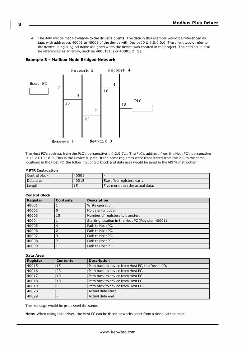
Exporting Variables from ConceptAs the ladder program is created, symbolic names for the various data points referenced can be defined usingthe Variable Editor. Additional symbols and constants that are not used by the ladder program can also bedefined.
Note: Although Concept can define variable names that begin with an underscore, such names are not allowedby the OPC server. The driver will modify invalid imported tag names as needed and note all name changes in theserver's Event Log.
www. kepware.com
13

Modbus Plus Driver
User defined data types are not currently supported by this driver. Records in the export file containingreferences to such types will be ignored. The following simple data types are supported:
Concept Data Type Generated Tag Data TypeBool BooleanByte WordDint LongInt ShortReal FloatTime DWordUdint DWordUint WordWord Word
Notes:
1. Unlocated variables that do not correspond to a physical address in the device are ignored by the driver.
2. Comments are allowed and may be included as the generated tag descriptions. For more information,refer to Variable Import Settings.
Exporting Variables From ConceptOnce the variables have been defined, the data must be exported from the Concept. To do so, follow theinstructions below.
1. Select File | Export. Then select the Variables: Text delimited format.
2. ClickOK. Next, specify the filter and separator settings.
Note: Although any filter settings can be chosen, this driver will only be able to read the exported data if thedefault semicolon separator is used.
www. kepware.com
14

Modbus Plus Driver
3. ClickOK to generate the file.
Exporting Variables from ProWORXIn order for ProWORX to export the necessary variable information, check the Symbols option under File |Preferences. Symbolic names for various data points referenced can be defined by using theDocumentEditor.
Note: ProWORX does not place many restrictions on variable names. The OPC Server, however, requires that tagnames consist of only alphanumeric characters and underscores, and that the first character not be anunderscore. The driver will modify invalid imported tag names as needed will inform when any name changes inthe server's Event Log.
ProWORX will also assign a data type of either BOOL or INT to the exported variables. The driver will create tags oftype Boolean and Short respectively. In order to generate tags with other data types, manually edit the exportedfile and use any of the supported Concept data types. For a list of supported types, refer to Exporting Variablesfrom Concept.
Exporting Variables From ProWORXOnce the variables have been defined, they must be exported from ProWORX. To do so, follow the instructionsbelow.
1. Select File | Utilities | Import/Export.
2. Select the Export and the Concept .TXT file format.
www. kepware.com
15

Modbus Plus Driver
Note: Descriptors are allowed and can be included as the generated tag descriptions. For more information,refer to Variable Import Settings.
3. ClickOK to generate the file.
Exporting Variables from Unity Pro XLFor information on exporting variables from Unity Pro XL, refer to the instructions below.
1. To start, open a Unity Pro XL project. In the Project Browser, double-click on Variables & FBInstances.
www. kepware.com
16
Modbus Plus Driver
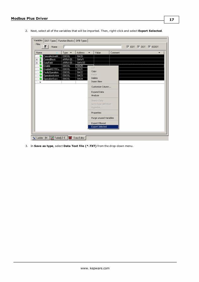
2. Next, select all of the variables that will be imported. Then, right-click and select Export Selected.
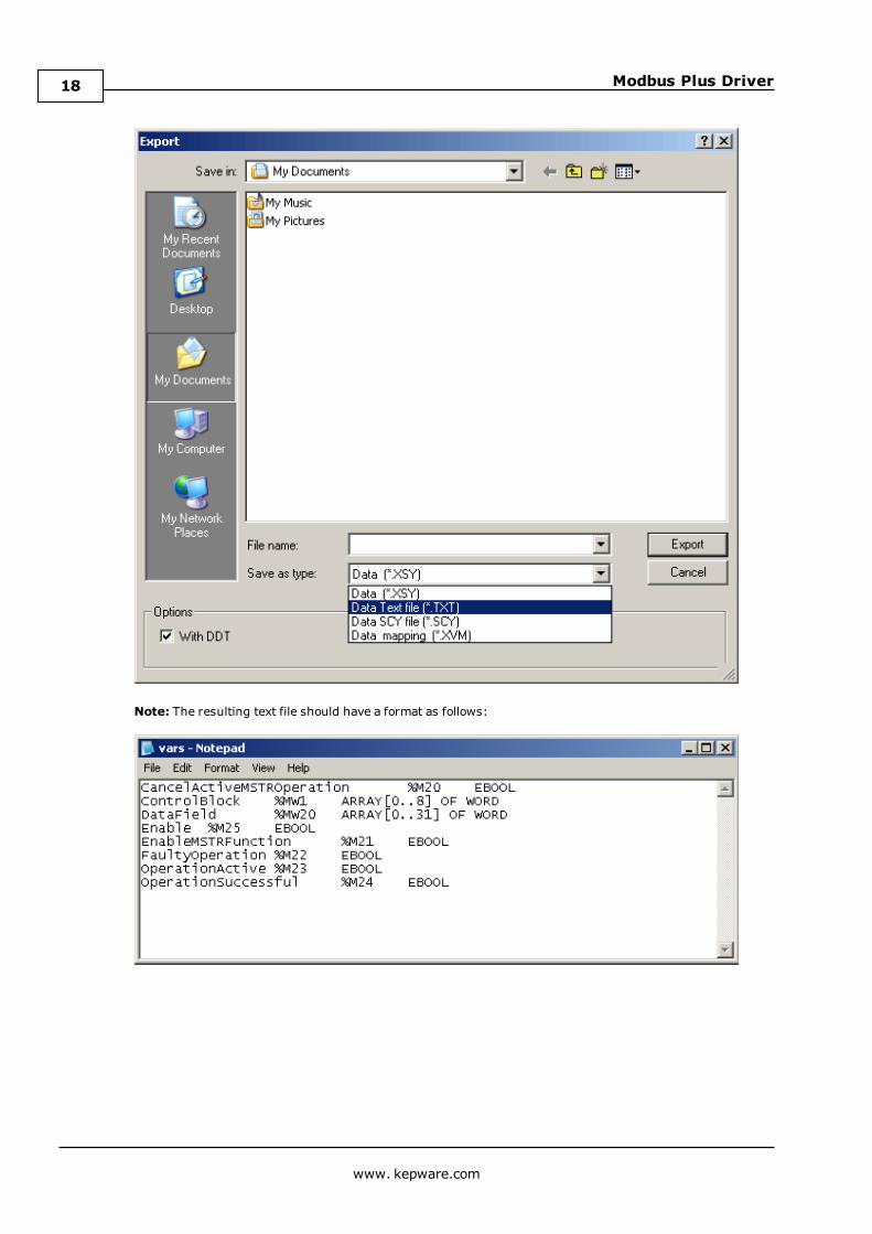
3. In Save as type, select Data Text file (*.TXT) from the drop-down menu.
www. kepware.com
17
Modbus Plus Driver
Note: The resulting text file should have a format as follows:
www. kepware.com
18

Modbus Plus Driver
Optimizing Modbus Plus CommunicationsThe following optimizations apply to the SA85 card only. Hilscher CIF card configurations only support 1 channelper adapter.
The Modbus Plus Driver has been designed to provide better throughput and take full advantage of the SA85card. Previously, the Modbus Plus Driver restricted users to configuring a single channel in the OPC Serverproject and required that all Modbus Plus devices that would be accessed be defined under this channel. Thismeant that the driver had to move between devices one at a time in order to make requests. Since the OPC Serverwas already designed to be efficient, the single channel scheme provided enough performance for mostapplication. With the advent of OPC as an enabling technology, however, the size of projects has increaseddramatically. To maintain a high level of performance, the Modbus Plus Driver is designed to operate at a highlevel of efficiency and performance.
Note: Before beginning these changes, users should back up the OPC server project directory in order toquickly return to previous settings if needed.
In this project, there is only one channel defined. All devices thatneed to be accessed are defined under that one channel. The ModbusPlus Driver must move from one device to the next as quickly aspossible to gather information at an effective rate. As more devicesare added or more information is requested from a single device, theupdate rate begins to suffer.
The latest version of the Modbus Plus Driver uses multiple channel definitions in order to boost the application'sperformance. In this configuration, each channel in the OPC server represents a separate path of execution. Byadding up to 8 additional channels, the application's work load is spread across the new channels. This createsmultiple paths of execution that run independently, and results in a significant increase in performance. Theimage below shows the same application reconfigured to use multiple channels.
www. kepware.com
19

Modbus Plus Driver
Each device has now been defined under its own channel. In this newconfiguration, the OPC Server can dedicate a single path of executionto the task of gathering data from a single device because each has itsown dedicated channel. If the application has 8 or less devices it canbe optimized as displayed.
Even if the application has more than 8 devices, there will still be again. While 8 or less devices may be ideal, the application will stillbenefit from additional channels. Although this means that within agiven channel the server must move from device to device, it can nowdo so with less devices to process on a single path.
Note: The 8 channel limit matches the multi-path limitations of theSA85 and Hilscher card as set by the manufacturer.
The application can be redesigned to support multiple channels easily even if there are a large number of tagsdefined under each device. For more information, follow the instructions below.
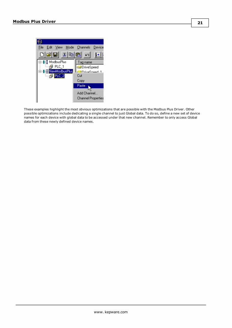
1. In the existing OPC server project that is still single channel-based, click Channels | Add Channel andthen name it as desired.
Note: In this example, it has been named "NewModbusPlus".
2. Next, cut PLC2 from theModbusPlus channel.
3. Paste it under the NewModbusPlus channel. The cut and paste functions quickly modify the applicationto take advantage of the new Modbus Plus Driver.
www. kepware.com
20
Modbus Plus Driver
These examples highlight the most obvious optimizations that are possible with the Modbus Plus Driver. Otherpossible optimizations include dedicating a single channel to just Global data. To do so, define a new set of devicenames for each device with global data to be accessed under that new channel. Remember to only access Globaldata from these newly defined device names.
www. kepware.com
21
Modbus Plus Driver
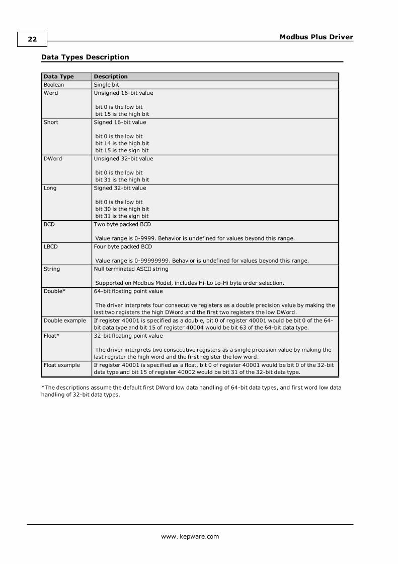
Data Types Description
Data Type DescriptionBoolean Single bitWord Unsigned 16-bit value
bit 0 is the low bitbit 15 is the high bit
Short Signed 16-bit value
bit 0 is the low bitbit 14 is the high bitbit 15 is the sign bit
DWord Unsigned 32-bit value
bit 0 is the low bitbit 31 is the high bit
Long Signed 32-bit value
bit 0 is the low bitbit 30 is the high bitbit 31 is the sign bit
BCD Two byte packed BCD
Value range is 0-9999. Behavior is undefined for values beyond this range.LBCD Four byte packed BCD
Value range is 0-99999999. Behavior is undefined for values beyond this range.String Null terminated ASCII string
Supported on Modbus Model, includes Hi-Lo Lo-Hi byte order selection.Double* 64-bit floating point value
The driver interprets four consecutive registers as a double precision value by making thelast two registers the high DWord and the first two registers the low DWord.
Double example If register 40001 is specified as a double, bit 0 of register 40001 would be bit 0 of the 64-bit data type and bit 15 of register 40004 would be bit 63 of the 64-bit data type.
Float* 32-bit floating point value
The driver interprets two consecutive registers as a single precision value by making thelast register the high word and the first register the low word.
Float example If register 40001 is specified as a float, bit 0 of register 40001 would be bit 0 of the 32-bitdata type and bit 15 of register 40002 would be bit 31 of the 32-bit data type.
*The descriptions assume the default first DWord low data handling of 64-bit data types, and first word low datahandling of 32-bit data types.
www. kepware.com
22
Modbus Plus Driver
Address DescriptionsAddress specifications vary depending on the model in use. Select a link from the following list to obtain specificaddress information for the model of interest.
Modbus AddressingTIO Module Addressing
Modbus AddressingFor this driver, the terms Slave and Unsolicited are used interchangeably.
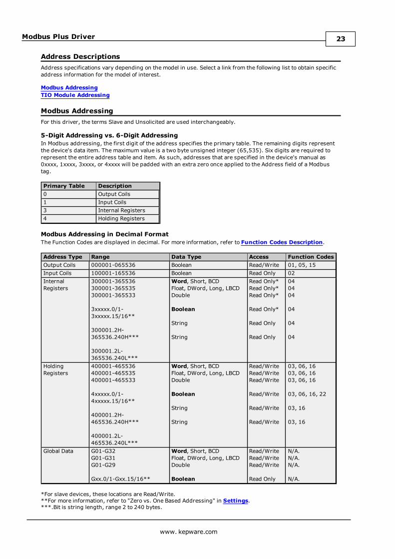
5-Digit Addressing vs. 6-Digit AddressingIn Modbus addressing, the first digit of the address specifies the primary table. The remaining digits representthe device's data item. The maximum value is a two byte unsigned integer (65,535). Six digits are required torepresent the entire address table and item. As such, addresses that are specified in the device's manual as0xxxx, 1xxxx, 3xxxx, or 4xxxx will be padded with an extra zero once applied to the Address field of a Modbustag.
Primary Table Description0 Output Coils1 Input Coils3 Internal Registers4 Holding Registers
Modbus Addressing in Decimal FormatThe Function Codes are displayed in decimal. For more information, refer to Function Codes Description.
Address Type Range Data Type Access Function CodesOutput Coils 000001-065536 Boolean Read/Write 01, 05, 15Input Coils 100001-165536 Boolean Read Only 02InternalRegisters
300001-365536300001-365535300001-365533
3xxxxx.0/1-3xxxxx.15/16**
300001.2H-365536.240H***
300001.2L-365536.240L***
Word, Short, BCDFloat, DWord, Long, LBCDDouble
Boolean
String
String
Read Only*Read Only*Read Only*
Read Only*
Read Only
Read Only
040404
04
04
04
HoldingRegisters
400001-465536400001-465535400001-465533
4xxxxx.0/1-4xxxxx.15/16**
400001.2H-465536.240H***
400001.2L-465536.240L***
Word, Short, BCDFloat, DWord, Long, LBCDDouble
Boolean
String
String
Read/WriteRead/WriteRead/Write
Read/Write
Read/Write
Read/Write
03, 06, 1603, 06, 1603, 06, 16
03, 06, 16, 22
03, 16
03, 16
Global Data G01-G32G01-G31G01-G29
Gxx.0/1-Gxx.15/16**
Word, Short, BCDFloat, DWord, Long, LBCDDouble
Boolean
Read/WriteRead/WriteRead/Write
Read Only
N/A.N/A.N/A.
N/A.
*For slave devices, these locations are Read/Write.**For more information, refer to "Zero vs. One Based Addressing" in Settings.***.Bit is string length, range 2 to 240 bytes.
www. kepware.com
23

Modbus Plus Driver
Modbus Addressing in Hexadecimal FormatAddress Type Decimal Range Data Type AccessOutput Coils H000001-H010000 Boolean Read/WriteInput Coils H100001-H110000 Boolean Read OnlyInternal Registers H300001-H310000
H300001-H30FFFFH300001-H30FFFD
H3yyyyy.0/1-H3yyyyy.F/10
H300001.2H-H3FFFF.240H
H300001.2L-H3FFFF.240L
Word, Short, BCDFloat, DWord, Long, LBCDDouble
Boolean
String
String
Read Only*Read Only*Read Only*
Read Only*
Read Only
Read OnlyHolding Registers H400001-H410000
H400001-H40FFFFH400001-H40FFFD
H4yyyyy.0/1-H4yyyyy.F/10
H400001.2H-H4FFFF.240H
H400001.2L-H4FFFF.240L
Word, Short, BCDFloat, DWord, Long, LBCDDouble
Boolean
String
String
Read/WriteRead/WriteRead/Write
Read/Write
Read/Write
Read/WriteGlobal Data HG01-HG20
HG01-HG1FHG01-HG1D
HGyy.0/1-HGyy.F/10
Word, Short, BCDFloat, DWord, Long, LBCDDouble
Boolean
Read/WriteRead/WriteRead/Write
Read Only
*For slave devices, these locations are Read/Write.**.Bit is string length, range 2 to 240 bytes.
Packed CoilsThe Packed Coil address type allows access to multiple consecutive coils as an analog value. This feature is onlyavailable when the Modbus model is in Master Mode. The syntax is as follows:
Output Coils: 0xxxxx#nnInput Coils: 1xxxxx#nn
where
l xxxxx is the address of the first coil. Both decimal and hexadecimal values are allowed.l nn is the number of coils that will be packed into an analog value. The valid range is 1-16, and onlydecimal values are allowed.
Note: The only valid data type is Word. Output Coils have Read/Write access, whereas Input Coils have Read Onlyaccess. The bit order will be such that the start address will be the Least Significant Bit (LSB) of analog value.
Write Only AccessAll Read/Write addresses may be set as Write Only by prefixing a "W" to the address (such as "W40001"), whichwill prevent the driver from reading the register at the specified address. Any attempts by the client to read aWrite Only tag will result in obtaining the last successful write value to the specified address. If no successfulwrites have occurred, then the client will receive 0/NULL for numeric/string values for an initial value.
Caution: Setting the client access privileges of Write Only tags to Read Only will cause writes to these tags tofail and the client to always receive 0/NULL for numeric/string values.
Mailbox ModeOnly Holding Registers are supported in Mailbox Mode. When read from a client, the data is read locally from acache, not from a physical device. When written to from a client, the data is written to both the local cache andalso the physical device as determined by the Device ID routing path. For more information, refer toMailboxMode.
Note: The Double data type is not supported.
www. kepware.com
24

Modbus Plus Driver
String SupportThe Modbus model supports reading and writing holding register memory as an ASCII string. When usingholding registers for string data, each register will contain two bytes of ASCII data. The order of the ASCII datawithin a given register can be selected when the string is defined. The length of the string can be from 2 to 240bytes and is entered in place of a bit number. The length must be entered as an even number. Appending eitheran "H" or "L" to the address specifies the byte order.
Examples1. To address a string starting at 40200 with a length of 100 bytes and HiLo byte order, enter "40200.100H".2. To address a string starting at 40500 with a length of 78 bytes and LoHi byte order, enter "40500.78L".
Note: The string length may be limited by the maximum size of the write request that the device will allow. If theerror message "Unable to write to address <address> on device<device>: Device responded with exceptioncode 3" is received in the server's event window while utilizing a string tag, the device did not like the string'slength. Users should shorten the string if possible.
Array SupportArrays are supported both for internal and holding register locations (including all data types except Boolean andstrings) and for input and output coils (Boolean data types). There are two ways to address an array. Thefollowing examples apply to holding registers:
4xxxx [rows] [cols]4xxxx [cols] with assumed row count equal to one.
For Word, Short and BCD arrays, the base address + (rows * cols) cannot exceed 65536. For Float, DWord, Longand Long BCD arrays, the base address + (rows * cols * 2) cannot exceed 65535. For all arrays, the total numberof registers being requested cannot exceed the holding register block size that was specified for this device.
Note: The base address for Global Data cannot exceed 32.
Function Codes Description
Decimal Hexadecimal Description01 0x01 Read Coil Status02 0x02 Read Input Status03 0x03 Read Holding Registers04 0x04 Read Internal Registers05 0x05 Force Single Coil06 0x06 Preset Single Register15 0x0F Force Multiple Coils16 0x10 Preset Multiple Registers22 0x16 Masked Write Register
Configuring the Device for Global Data CommunicationsGlobal Data is supported by both the SA85 and Hilscher CIF interface cards. It is only accessible from a singlenetwork. For example, "7.0.0.0.0" can access global data, but "7.1.0.0.0" cannot.
Note: Unsolicited mode does not support Global Data.
Writing Global Data to a DeviceThe Host PC's address from the PLC's perspective is 2.0.0.0.0. The PLC's address from the Host PC's perspectiveis 9.0.0.0.0. This is the Device ID path. Users must configure the addresses that the device will read to and writefrom in the programming software.
Control BlockRegister Contents DescriptionControl [1] 5 Function Code for writing Global Data.Control [2] -
0 = No Error.
The error code. This may not be changed.
Control [3] 32 The number of words to write from state RAM toglobal memory. The maximum is 32 bits.
www. kepware.com
25

Modbus Plus Driver
Register Contents DescriptionControl [4] - Reserved.*Control [5] 2 The Modbus Plus node address to which data is
being sent.Control [6] 0 Path to Host PC.Control [7] 0 Path to Host PC.Control [8] 0 Path to Host PC.Control [9] 0 Path to Host PC.
*This register is application-specific.
Data AreaRegister Contents DescriptionDataField [1]-DataField [32] Data N/A.
Reading Global Data from the DeviceThe Host PC's address from the PLC's perspective is 2.0.0.0.0. The PLC's address from the Host PC's perspectiveis 9.0.0.0.0. This is the Device ID path.
Control BlockRegister Contents DescriptionControl [1] 6 Function Code for reading Global Data.Control [2] -
0 = No Error.
The error code. This may not be changed.
Control [3] 32 The number of words to write from state RAM toglobal memory. The maximum is 32 bits.
Control [4] - Reserved.*Control [5] 2 The Modbus Plus node address from which data is
read.Control [6] 0 Path to Host PC.Control [7] 0 Path to Host PC.Control [8] 0 Path to Host PC.Control [9] 0 Path to Host PC.
*This register is application-specific.
Data AreaRegister Contents DescriptionDataField [1]-DataField [32] Data N/A.
TIO Module AddressingMailbox Mode is not supported for this model.
TIO Module Addressing in DecimalAddress Type Range Data Type AccessData I/O* 400001
400001.0/1-400001.15/16**
Word, Short
Boolean
Read/Write
Read/WriteData Input - Latched 400257
400257.0/1-400257.15/16**
Word, Short
Boolean
Read Only
Read OnlyModule Timeout 461441
461441.0/1-461441.15/16**
Word, Short
Boolean
Read/Write
Read/WriteModule Status 463489-463497
4xxxxx.0/1-4xxxxx.15/16**
Word, Short
Boolean
Read Only
Read OnlyModule ASCII Header 464513 String Read Only
www. kepware.com
26

Modbus Plus Driver
*The value read from a Data I/O location comes from the module's input register. When writing to this location,the value that is sent will modify the module's output register. Therefore, the value read at this location does notcorrespond to the value previously written to this location.**For more information, refer to "Zero vs. One Based Addressing" in Settings.
TIO Module Addressing in HexadecimalAddress Type Range Data Type AccessData I/O* H40001
H40001.0/1-H40001.F/10
Word, Short
Boolean
Read/Write
Read/WriteData Input - Latched H40101
H40101.0/1-40101.F/10
Word, Short
Boolean
Read Only
Read OnlyModule Timeout H4F001
H4F001.0/1-H4F001.F/10
Word, Short
Boolean
Read/Write
Read/WriteModule Status H4F801-H4F809
H4yyyy.0/1-H4yyyy.F/10
Word, Short
Boolean
Read Only
Read OnlyModule ASCII Header H4FC01 String Read Only
*The value read from a Data I/O location comes from the module's input register. When writing to this location,the value that is sent will modify the module's output register. Therefore, the value read at this location does notcorrespond to the value previously written to this location.
www. kepware.com
27

Modbus Plus Driver
Error DescriptionsThe following messages may be generated. Click on the link for a description of the message.
Address Validation MessagesAddress <address> is out of range for the specified device or register.Array size is out of range for address <address>.Array support is not available for the specified address: <address>.Data type <type> is not valid for device address <address>.Device address <address> contains a syntax error.Device address < address> is read only.Missing address.
Automatic Tag Database Generation MessagesDescription truncated for import file record number <record> .Error parsing import file record number <record> , field <field>.File exception encountered during tag import.Imported tag name <tag name> is invalid. Name changed to <tag name>.Tag <tag name> could not be imported because data type <data type> is not supported.Tag import failed due to low memory resources.
Device Specific MessagesAddress block error address responded with exception 132.Bad address in block [<start address> to <end address> ] on device <device name>.Bad array spanning [<address> to <address>] on device <device name>.Block address [<start address> to <end address> ] on device <device name> responded withexception <exception code>.Error opening MBPLUS path: <ID>.Unable to communicate with MBPLUS.VXD.Unable to open MBPLUS slave path.Unable to read from address <address> on device <device>. Device responded with exception code<code>.Unable to read from address <array address> on device <device>, board responded with exceptioncode <code>.Unable to start MBPLUS.SYS device.Unable to write to address <address> on device <device>. Device responded with exception code<code>.Unable to write to address <array address> on device <device>, board responded with exceptioncode <code>.
Device Status MessagesDevice <device name> is not responding.Started MBPLUS.SYS device.Unable to write to <address> on device <device name>.
Exception CodesModbus Exception CodesHilscher CIF Exception Codes
www. kepware.com
28

Modbus Plus Driver
Address <address> is out of range for the specified device or register.Error Type:Warning
Possible Cause:A tag address that has been specified statically references a location that is beyond the range of supportedlocations for the device.
Solution:Verify that the address is correct; if it is not, re-enter it in the client application.
Array size is out of range for address <address>.Error Type:Warning
Possible Cause:A tag address that has been specified statically is requesting an array size that is too large for the address type orblock size of the driver.
Solution:Re-enter the address in the client application to specify a smaller value for the array or a different starting point.
Array support is not available for the specified address: <address>.Error Type:Warning
Possible Cause:A tag address that has been specified statically contains an array reference for an address type that doesn'tsupport arrays.
Solution:Re-enter the address in the client application to remove the array reference or correct the address type.
Data Type <type> is not valid for device address <address>.Error Type:Warning
Possible Cause:A tag address that has been specified statically has been assigned an invalid data type.
Solution:Modify the requested data type in the client application.
Device address <address> contains a syntax error.Error Type:Warning
Possible Cause:A tag address that has been specified statically contains one or more invalid characters.
Solution:Re-enter the address in the client application.
Device address <address> is read only.Error Type:Warning
Possible Cause:
www. kepware.com
29
Modbus Plus Driver
A tag address that has been specified statically has a requested access mode that is not compatible with what thedevice supports for that address.
Solution:Change the access mode in the client application.
Missing address.Error Type:Warning
Possible Cause:A tag address that has been specified statically has no length.
Solution:Re-enter the address in the client application.
Description truncated for import file record number <record>.Error Type:Warning
Possible Cause:The tag description given in specified record is too long.
Solution:The driver will truncate the description as needed. To prevent this error in the future, edit the variable import fileto change the description if possible.
Error parsing import file record number <record>, field <field>.Error Type:Serious
Possible Cause:The specified field in the variable import file could not be parsed because it is longer than expected or invalid.
Solution:Edit the variable import file to change the offending field if possible.
File exception encountered during tag import.Error Type:Serious
Possible Cause:The variable import file could not be read.
Solution:Regenerate the variable import file.
Imported tag name <tag name> is invalid. Name changed to <tag name>.Error Type:Warning
Possible Cause:The tag name encountered in the variable import file contained invalid characters.
Solution:The driver will construct a valid name based on the one from the variable import file. To prevent this error in thefuture, and to maintain name consistency, change the name of the exported variable if possible.
www. kepware.com
30
Modbus Plus Driver
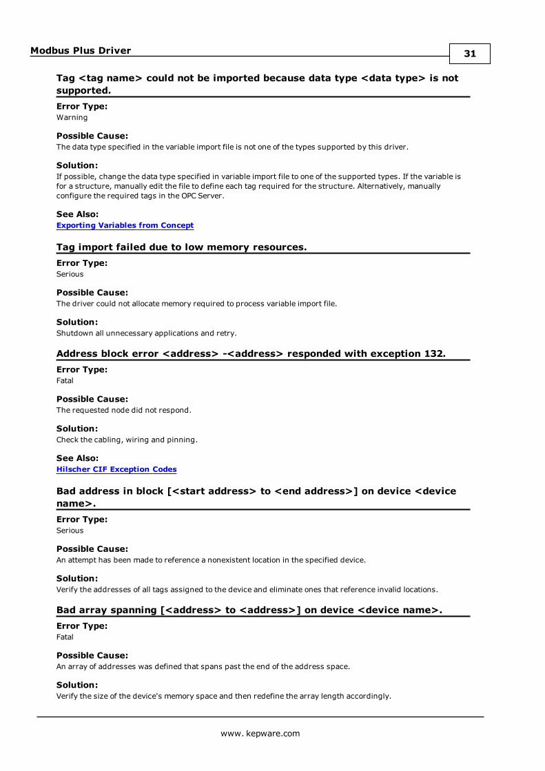
Tag <tag name> could not be imported because data type <data type> is notsupported.Error Type:Warning
Possible Cause:The data type specified in the variable import file is not one of the types supported by this driver.
Solution:If possible, change the data type specified in variable import file to one of the supported types. If the variable isfor a structure, manually edit the file to define each tag required for the structure. Alternatively, manuallyconfigure the required tags in the OPC Server.
See Also:Exporting Variables from Concept
Tag import failed due to low memory resources.Error Type:Serious
Possible Cause:The driver could not allocate memory required to process variable import file.
Solution:Shutdown all unnecessary applications and retry.
Address block error <address> -<address> responded with exception 132.Error Type:Fatal
Possible Cause:The requested node did not respond.
Solution:Check the cabling, wiring and pinning.
See Also:Hilscher CIF Exception Codes
Bad address in block [<start address> to <end address>] on device <devicename>.Error Type:Serious
Possible Cause:An attempt has been made to reference a nonexistent location in the specified device.
Solution:Verify the addresses of all tags assigned to the device and eliminate ones that reference invalid locations.
Bad array spanning [<address> to <address>] on device <device name>.Error Type:Fatal
Possible Cause:An array of addresses was defined that spans past the end of the address space.
Solution:Verify the size of the device's memory space and then redefine the array length accordingly.
www. kepware.com
31
Modbus Plus Driver
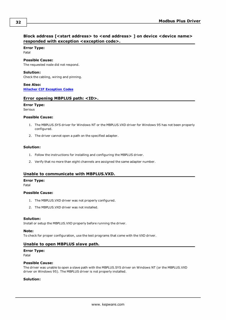
Block address [<start address> to <end address> ] on device <device name>responded with exception <exception code>.Error Type:Fatal
Possible Cause:The requested node did not respond.
Solution:Check the cabling, wiring and pinning.
See Also:Hilscher CIF Exception Codes
Error opening MBPLUS path: <ID>.Error Type:Serious
Possible Cause:
1. The MBPLUS.SYS driver for Windows NT or the MBPLUS.VXD driver for Windows 95 has not been properlyconfigured.
2. The driver cannot open a path on the specified adapter.
Solution:
1. Follow the instructions for installing and configuring the MBPLUS driver.
2. Verify that no more than eight channels are assigned the same adapter number.
Unable to communicate with MBPLUS.VXD.Error Type:Fatal
Possible Cause:
1. The MBPLUS.VXD driver was not properly configured.
2. The MBPLUS.VXD driver was not installed.
Solution:Install or setup the MBPLUS.VXD properly before running the driver.
Note:To check for proper configuration, use the test programs that come with the VXD driver.
Unable to open MBPLUS slave path.Error Type:Fatal
Possible Cause:The driver was unable to open a slave path with the MBPLUS.SYS driver on Windows NT (or the MBPLUS.VXDdriver on Windows 95). The MBPLUS driver is not properly installed.
Solution:
www. kepware.com
32
Modbus Plus Driver
1. Verify that the MBPLUS device can be started and stopped manually using the Control Panel | Devicesapplet. When the MBPLUS.SYS driver is started manually, the modbus_unsolicited.dll driver will also beable to start the driver.
2. Install or setup the MBPLUS.VXD properly before running the driver.
Note:To check for proper configuration, use the test programs that come with the VXD driver.
Unable to read from address <address> on device <device>. Deviceresponded with exception code <code>.Error Type:Warning
Possible Cause:SeeModbus Exception Codes for a description of the exception code.
Solution:SeeModbus Exception Codes for a description of corrective actions.
See Also:Modbus Exception Codes
Unable to read from address <array address> on device <device>, boardresponded with exception code <code>.Error Type:Warning
Possible Cause:
1. The adapter may not exist.
2. Depends on error.
Solution:
1. Verify that the proper adapter number has been chosen in Channel Properties. Use SyCon to determineadapter ordering.
2. Refer to the SyCon User Manual.
Note: Does not apply to the SA85 card. Code -1, -33 for the Hilscher CIF card.
Unable to start MBPLUS.SYS device.Error Type:Fatal
Possible Cause:The MBPLUS.SYS driver was not properly configured.
Solution:Verify that the MBPLUS device can be started and stopped manually using the Control Panel | Devices applet.When the MBPLUS.SYS driver is started manually, the modbus_unsolicited.dll driver will also be able to start thedriver.
www. kepware.com
33
Modbus Plus Driver
Unable to write to address <address> on device <device>: Device respondedwith exception code <code>.Error Type:Warning
Possible Cause:SeeModbus Exception Codes for a description of the exception code.
Solution:SeeModbus Exception Codes for a description of corrective actions to be taken.
See Also:Modbus Exception Codes
Unable to write to address <array address> on device <device>, boardresponded with exception code <code>.Error Type:Warning
Possible Cause:
1. The adapter may not exist.
2. Depends on error.
Solution:
1. Verify that the proper adapter number has been chosen in Channel Properties. Use SyCon to determineadapter ordering.
2. Refer to the SyCon User Manual.
Note: Does not apply to the SA85 card. Code -1, -33 for the Hilscher CIF card.
Device <device name> is not responding.Error Type:Serious
Possible Cause:
1. The PLC network card may not be correctly installed in the Host PC.
2. The named device may not be connected to the PLC network.
3. The named device may have been assigned an incorrect network ID.
4. The driver cannot open a path on the specified adapter.
5. The response from the device took longer to receive than the amount of time specified in the "RequestTimeout" device setting.
Solution:
1. Verify the network card installation using the supplied utility software.
2. Check the PLC network connections.
3. Verify that the network ID given to the named device matches that of the actual device.
www. kepware.com
34
Modbus Plus Driver
4. Verify that no more than eight channels are assigned the same adapter number.
5. Increase the Request Timeout setting so that the entire response can be handled.
Started MBPLUS.SYS device.Error Type:Information
Possible Cause:This message is posted by the driver when the MBPLUS.SYS device driver is started successfully. This is aWindows NT only message and will not be seen if the MBPLUS.SYS driver is already running when the driverstarts.
Solution:N/A
Unable to write to <address> on device <device name>.Error Type:Serious
Possible Cause:
1. The PLC network card may not be correctly installed in the host PC.
2. The named device may not be connected to the PLC network.
3. The named device may have been assigned an incorrect network ID.
Solution:
1. Verify the network card installation using the supplied utility software.
2. Check the PLC network connections.
3. Verify the network ID given to the named device matches that of the actual device.
www. kepware.com
35
Modbus Plus Driver
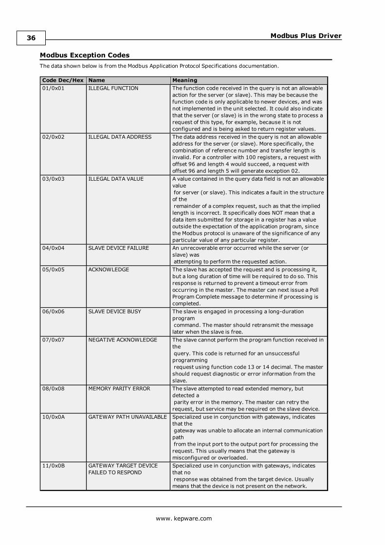
Modbus Exception CodesThe data shown below is from the Modbus Application Protocol Specifications documentation.
Code Dec/Hex Name Meaning01/0x01 ILLEGAL FUNCTION The function code received in the query is not an allowable
action for the server (or slave). This may be because thefunction code is only applicable to newer devices, and wasnot implemented in the unit selected. It could also indicatethat the server (or slave) is in the wrong state to process arequest of this type, for example, because it is notconfigured and is being asked to return register values.
02/0x02 ILLEGAL DATA ADDRESS The data address received in the query is not an allowableaddress for the server (or slave). More specifically, thecombination of reference number and transfer length isinvalid. For a controller with 100 registers, a request withoffset 96 and length 4 would succeed, a request withoffset 96 and length 5 will generate exception 02.
03/0x03 ILLEGAL DATA VALUE A value contained in the query data field is not an allowablevaluefor server (or slave). This indicates a fault in the structureof theremainder of a complex request, such as that the impliedlength is incorrect. It specifically does NOT mean that adata item submitted for storage in a register has a valueoutside the expectation of the application program, sincethe Modbus protocol is unaware of the significance of anyparticular value of any particular register.
04/0x04 SLAVE DEVICE FAILURE An unrecoverable error occurred while the server (orslave) wasattempting to perform the requested action.
05/0x05 ACKNOWLEDGE The slave has accepted the request and is processing it,but a long duration of time will be required to do so. Thisresponse is returned to prevent a timeout error fromoccurring in the master. The master can next issue a PollProgram Complete message to determine if processing iscompleted.
06/0x06 SLAVE DEVICE BUSY The slave is engaged in processing a long-durationprogramcommand. The master should retransmit the messagelater when the slave is free.
07/0x07 NEGATIVE ACKNOWLEDGE The slave cannot perform the program function received inthequery. This code is returned for an unsuccessfulprogrammingrequest using function code 13 or 14 decimal. The mastershould request diagnostic or error information from theslave.
08/0x08 MEMORY PARITY ERROR The slave attempted to read extended memory, butdetected aparity error in the memory. The master can retry therequest, but service may be required on the slave device.
10/0x0A GATEWAY PATH UNAVAILABLE Specialized use in conjunction with gateways, indicatesthat thegateway was unable to allocate an internal communicationpathfrom the input port to the output port for processing therequest. This usually means that the gateway ismisconfigured or overloaded.
11/0x0B GATEWAY TARGET DEVICEFAILED TO RESPOND
Specialized use in conjunction with gateways, indicatesthat noresponse was obtained from the target device. Usuallymeans that the device is not present on the network.
www. kepware.com
36

Modbus Plus Driver
Note: For this driver, the terms Slave and Unsolicited are used interchangeably.
Hilscher CIF Exception CodesThe data below is from the Modbus Application Protocol Specifications documentation.
CIF Code Name Meaning111 ILLEGAL
FUNCTIONThe function code received in the query is not an allowable action for theserver (or slave). This may be because the function code is only applicableto newer devices, and was not implemented in the unit selected. It couldalso indicate that the server (or slave) is in the wrong state to process arequest of this type, for example because it is unconfigured and is beingasked to return register values.
114 SLAVE DEVICEFAILURE
An unrecoverable error occurred while the server (or slave) was attemptingto perform the requested action.
Note: For this driver, the terms Slave and Unsolicited are used interchangeably.
www. kepware.com
37

Modbus Plus Driver
Index
5
5-Digit Addressing 23
6
6-Digit Addressing 23
A
Adapter 9Address <address> is out of range for the specified device or register. 29Address block error <address> -<address> responded with exception 132. 31Address Descriptions 23Address Validation 28Array size is out of range for address <address>. 29Array Support 25Array support is not available for the specified address: <address>. 29Automatic Tag Database Generation 13
B
Bad address in block [<start address> to <end address>] on device <device name>. 31Bad array spanning [<address> to <address>] on device <device name>. 31BCD 22Bit Mask 10Block address [<start address> to <end address> ] on device responded with exception. 32Block Read 9Block Sizes 9Boolean 22Bridged Network 8Byte Order 11
C
Coil Block Sizes 9Concept 12-13Configuring the Device for Global Data Communications 25
D
Data Encoding 11Data Master 5Data Slave 6Data Type <type> is not valid for device address <address>. 29Data Types Description 22Database Creation 13Decimal 23, 25-26Default Block Sizes 9Description truncated for import file record number <record>. 30Device <device name> is not responding. 34
www. kepware.com
38
Modbus Plus Driver
Device address <address> contains a syntax error. 29Device address <address> is read only. 29Device ID(PLC Network Address) 5Device Setup 5Display Descriptions 12DWord 22
E
Error Descriptions 28Error opening MBPLUS path: <ID>. 32Error parsing import file record number <record> field <field>. 30Exception Codes 36-37Exporting Variables from Concept 13Exporting Variables from ProWORX 15Exporting Variables from Unity Pro XL 16External Dependencies 4
F
File exception encountered during tag import. 30First DWord Low 11Float 22Force Multiple Co 25Force Single Coil 25Function 05 or 15 10Function 06 or 16 10Function Codes 23Function Codes Description 25
G
Global Data 25
H
Hexadecimal 24-25, 27Hilscher 6, 9Hilscher CIF Card 4-5, 9Hilscher CIF Exception Codes 37Hilscher SyCon 4Holding Registe 23Holding Register 10
I
Imported tag name <tag name> is invalid. Name changed to <tag name>. 30Input Coils 23Interface Cards 5Internal Registers 23
L
LBCD 22
www. kepware.com
39

Modbus Plus Driver
Long 22
M
Mailbox 5Mailbox Mode 24Masked Write Register 25Master 5MBPLUS 4MBX 4Missing address. 30Modbus Addressing 23Modbus Byte Order 10Modbus Exception Codes 36Modicon 4Modicon PLC 9Modicon SA85 Network Card 4MSTR 6Multiple channels 19
O
One-Based Addressing 9Optimizing Your Modbus Plus Communicaitons 19Output Coils 23
P
Packed Coils 24PCI-85 4Performance 19Polling 5Preset Multiple Registers 25Preset Single Register 25Project 20ProWORX 12, 15
R
Read Coil Status 25Read Holding Registers 25Read Input Status 25Read Internal Registers 25Register Block Sizes 9
S
SA8 4SA85 card 19SA85 Card 5, 9Schneider 4Settings 9Short 22Signed 22Single channel 21Slave 5
www. kepware.com
40

Modbus Plus Driver
Slave Path (Unsolicited) 6Solicited 5Started MBPLUS.SYS device. 35String 22String Support 25Supported 5
T
Tag <tag name> could not be imported because data type <data type> is not supported. 31Tag import failed due to low memory resources. 31TIO Module 9TIO Module Addressing 26
U
Unable to communicate with MBPLUS.VXD. 32Unable to open MBPLUS slave path. 32Unable to read from <array address> on device, board responded with exception code. 33Unable to read from address on device. Device responded with exception code. 33Unable to start MBPLUS.SYS device. 33Unable to write to <address> on device <device name>. 35Unable to write to <array address> on device, board responded with exception code. 34Unable to write to address on device. Device responded with exception code. 34Unity Pro XL 16Unsigne 22Unsolicited 4-5Use Modicon Bit Ordering 11
V
Variable Import File 13Variable Import Settings 12Variables 14
W
Word 22Write Only Access 24
Z
Zero-Based Addressing 9
www. kepware.com
41