modbus manuel - georgin.eu · modbus manual - gmb series 5 georgin modbus i/o modules gmb 96500...
TRANSCRIPT

www.georgin.com
GMB Series
ModbusManuelModbus Manuel

Modbus Manual - GMB Series
2 www.georgin.com
Before StartupWhen operating the signal converter, certain parts of the module can carry dan-gerous voltage ! Ignoring the warnings can lead to serious injury and/or cause damage !
The signal converter should only be installed and put into operation by qualified staff. The staff must have studied the warnings in these operating instructions thoroughly.
The signal converter may not be put into operation if the housing is open.
In applications with high operating voltages sufficient distance and isolation as well as shock protection must be ensured.
Safe and trouble-free operation of this device can only be guaranteed if trans-port, storage and installation are carried out correctly and operation and main-tenance are carried out with care.
Appropriate safety measures against electrostatic discharge (ESD) should be taken during range selection and assembly on the transmitter !
!

Modbus Manual - GMB Series
3www.georgin.com
New ultra-compact Modbus RTU I/O ModulesFreely scalable up to 247 units in one Modbus segment
Extremely slim, only 6.2 mm installation width
Easy configurable via DIP switches or USB interface
Protective galvanic separation between all circuits,test voltage 3 kV AC
In-Rail-Bus Connector for Power and Modbus
Protection against over voltage, polarity error and short circuit at all terminals
Long service life, extremely low failure rate due to reduced self heating
Made in Germany, 5 years warranty
The Georgin Modbus RTU I/O Modules combine complex field and control requirements such as protective galvanic isolation, maximum signal integrity and highest reliability with fast measurement data conversion and field bus provision.
Up to 4 fully isolated I/Os are available in the 6.2 mm slim modules. The configuration can be made via DIP switch or USB interface. In addition to standard signals, mA, V, mV, R, Pot, Hz, PWM and all current industrial sensors can be processed.
Power supply and bus connections are pre-wired on standard DIN rail by the In-Rail-Bus. All terminals are protected against short circuit, over voltage and polarity reversal. The protective galvanic isolation with 3 kV test voltage permits working voltages up to 300 V. A low bus load allows up to 247 modules (988 I/Os) in one Modbus segment.
The low-power design ensures minimum self-heating for a wide temperature range. The high separation quality and short response time guarantee an economic integration in new plants and retrofit projects.
General Data
Protocol Modbus RTU Module Addressing : 1 … 247Configuration Parity : Even, Odd, None Response Delay : 1 … 1000 msBaud Rate 300, 600, 1200, 2400, 4800, 9600, 19200, 38400, 57600, 115200Connectivity Up to 247 Georgin Modbus Devices (1/8 Load)
Test voltage 3 kV AC, 50 Hz, 1 min., I/Os against Modbus/PowerAmbient temperature Operation : -25 °C to +70 °C Transport and storage : -40 °C to +85 °C
Power supply 24 V DC, voltage range 16.8 V… 31.2 V DC
Construction 99 x 107 x 6.2 mm (H x T x B), protection class IP 20mounting on 35 mm DIN rail acc. to EN 60715

Modbus Manual - GMB Series
4 www.georgin.com
Modbus Manual - GMB Series
5www.georgin.com
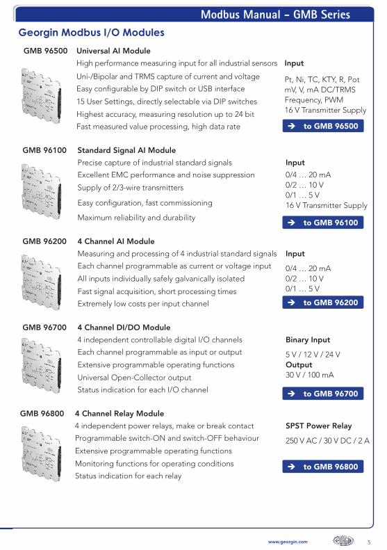
Georgin Modbus I/O ModulesGMB 96500 Universal AI Module
High performance measuring input for all industrial sensors Input
Uni-/Bipolar and TRMS capture of current and voltage Pt, Ni, TC, KTY, R, PotmV, V, mA DC/TRMSFrequency, PWM16 V Transmitter Supply
Easy configurable by DIP switch or USB interface
15 User Settings, directly selectable via DIP switches
Highest accuracy, measuring resolution up to 24 bit
Fast measured value processing, high data rate
GMB 96100 Standard Signal AI Module
Precise capture of industrial standard signals Input
Excellent EMC performance and noise suppression 0/4 … 20 mA0/2 … 10 V0/1 … 5 V16 V Transmitter Supply
Supply of 2/3-wire transmitters
Easy configuration, fast commissioning
Maximum reliability and durability
GMB 96200 4 Channel AI Module
Measuring and processing of 4 industrial standard signals Input
Each channel programmable as current or voltage input 0/4 … 20 mA0/2 … 10 V0/1 … 5 V
All inputs individually safely galvanically isolated
Fast signal acquisition, short processing times
Extremely low costs per input channel
GMB 96700 4 Channel DI/DO Module
4 independent controllable digital I/O channels Binary Input
Each channel programmable as input or output 5 V / 12 V / 24 VOutput30 V / 100 mA
Extensive programmable operating functions
Universal Open-Collector output
Status indication for each I/O channel
GMB 96800 4 Channel Relay Module
4 independent power relays, make or break contact SPST Power Relay
Programmable switch-ON and switch-OFF behaviour 250 V AC / 30 V DC / 2 AExtensive programmable operating functions
Monitoring functions for operating conditions
Status indication for each relay
to GMB 96500
to GMB 96100
to GMB 96200
to GMB 96700
to GMB 96800

Modbus Manual - GMB Series
6 www.georgin.com
1. Introduction
With the GMB series Georgin Automation offers different analogue and digital input options. The Modbus interface with RTU protocol on the RS485 physical layer enables robust communication in rough industrial environment. Because of their 1/8 unit load transceivers it is possible to connect 247 Georgin GMB series devices as Modbus slaves with one master without the need for repeater.
This manual is mainly intended to deliver devices specific information about the GMB series. Although it covers some basics about the Modbus protocol and the RS485 standard we recommend reading the referring Modbus Protocol Specifications [1] and the Modbus Serial Line Protocol and Implementation Guide [2] which can be found here : http : //www.modbus.org/specs.php.
2. Modbus RTU over RS485
2.1. Modbus RTU Protocol
The GMB devices implement the Modbus RTU Protocol. The Modbus protocol is a single masterprotocol. Therefore a slave only sends answer messages to former requests of the Modbus masterdevice. The Modbus RTU standard [1] defines a binary communication inside the Modbus Frame. AModbus RTU message frame consists of the following parts :
Address Field1 Byte
Function code1 Byte
Data0 ...252 Byte
CRC2 Byte
The 4 fields have the following meaning :
1. Address Field : States the address of the slave that is addressed in the actual communication. The master itself has no address. The address “0” is reserved for broadcast communication. The addresses 248 to 255 are actually restricted by the Modbus standard.
2. Function Code : A 1 Byte field that contains the command the slave has to process. Thefunction codes are standardized for all Modbus devices. The GMB devices implement only alimited subset of function codes, depending on the devices.
3. Data : This field contents the information referring to the function code (e.g. the address of arequested register). The data needed for each function code can be found in [1].
4. CRC : The last field contains the two bytes of the CRC used to verify the data frame.
A start or an end of a Modbus RTU frame is indicated by a 3.5 Byte long pause which means that nodevices on the network sends data.
Modbus Manual - GMB Series
7www.georgin.com
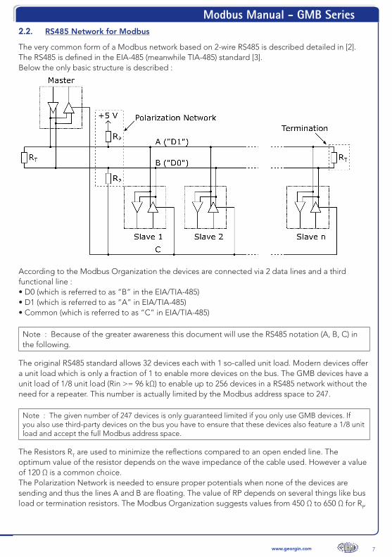
2.2. RS485 Network for Modbus
The very common form of a Modbus network based on 2-wire RS485 is described detailed in [2]. The RS485 is defined in the EIA-485 (meanwhile TIA-485) standard [3]. Below the only basic structure is described :
According to the Modbus Organization the devices are connected via 2 data lines and a third functional line :• D0 (which is referred to as “B” in the EIA/TIA-485)• D1 (which is referred to as “A” in EIA/TIA-485)• Common (which is referred to as “C” in EIA/TIA-485)
Note : Because of the greater awareness this document will use the RS485 notation (A, B, C) in the following.
The original RS485 standard allows 32 devices each with 1 so-called unit load. Modern devices offer a unit load which is only a fraction of 1 to enable more devices on the bus. The GMB devices have aunit load of 1/8 unit load (Rin >= 96 kΩ) to enable up to 256 devices in a RS485 network without theneed for a repeater. This number is actually limited by the Modbus address space to 247.
Note : The given number of 247 devices is only guaranteed limited if you only use GMB devices. If you also use third-party devices on the bus you have to ensure that these devices also feature a 1/8 unit load and accept the full Modbus address space.
The Resistors RT are used to minimize the reflections compared to an open ended line. The optimum value of the resistor depends on the wave impedance of the cable used. However a value of 120 Ω is a common choice.The Polarization Network is needed to ensure proper potentials when none of the devices aresending and thus the lines A and B are floating. The value of RP depends on several things like busload or termination resistors. The Modbus Organization suggests values from 450 Ω to 650 Ω for RP.

Modbus Manual - GMB Series
8 www.georgin.com
The use of a polarization Network is strongly suggested to obtain a robust stable network. Thepolarization resistors are usually integrated in the master device.
Note : Devices of the GMB series don’t have internal resistors for termination or polarization.
For further details about the wiring of a Modbus RS485 network refer to [2] and [3].
2.3. Connections
The primary way to connect the GMB devices is the rear In-Rail-Bus connector (A-E). Third-partydevices without the In-Rail-Connector can be connected by an In-Rail-Bus Power-Terminals (order no. : GZU 1401; GZU 1402). Some GMB devices also internally connect the Modbus signals to theterminals 5, 6 and 8. An overview of all connections on the enclosure is shown below :
RS485 (Modbus)signal name
In-Rail-Bus connectorOptional Screw
terminalsFunction
A (D1) A 5 Modbus A
B (D0) B 6 Modbus B
C (Common) C 8 Supply GND
- D 7 Supply +24 V
- E - Fault Signal (opt.)
Note : Not all of the GMB devices have the Modbus signals and the power supply connectedto the terminals. See user instruction of the specific device for details.

Modbus Manual - GMB Series
9www.georgin.com
2.4. Structure of the data formats in the Modbus frame
Modbus communicates the data generally as 16-bit registers or as groups of 16-bit registers. Data register, as LONG and FLOAT values, occupy multiple contiguous registers and are transmitted in one bus telegram.
The Modbus specification not defines the register order for LONG and FLOAT in the transmission, so the order is configurable at register 45002 (factory setting is 0 x 0001). The green values below are valid setting is 0 x 0000, the configurated setting is stored permanently.
Format In the Modbus frame Register order Example
INT16
UINT16
…High-Low… 1234d = 0x04D2 = ...|04|D2|…
INT32
UINT32
…High-MedH-MedL-Low…
…MedL-Low-High-MedH…
Reg. 45002 = 0x0001 1234512345d = 0x499529D9 = …|49|95|29|D9|…
1234512345d = 0x29D94995 = …|29|D9|49|95|…
FLOAT …High-MedH-MedL-Low…
…MedL-Low-High-MedH…
Reg. 45002 = 0x0001
Reg. 45002 = 0x0000
1,23 = 0x3F9D70A4 = …|3F|9D|70|A4|…
1,23 = 0x70A43F9D = …|70|A4|3F|9D|…
16 Char …c1-c2-c3…c14-c15-c16… 'ABCDEFGHIJKLMNOP' = …|41|42|…|4F|50|…

Modbus Manual - GMB Series
10 www.georgin.com
Modbus Manual - GMB Series
11www.georgin.com
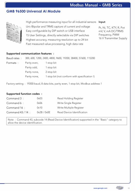
GMB 96500 Universal AI Module
High performance measuring input for all industrial sensors Input
Uni-/Bipolar and TRMS capture of current and voltage Pt, Ni, TC, KTY, R, PotmV, V, mA DC/TRMSFrequency, PWM16 V Transmitter Supply
Easy configurable by DIP switch or USB interface
15 User Settings, directly selectable via DIP switches
Highest accuracy, measuring resolution up to 24 bit
Fast measured value processing, high data rate
Supported communication features :
Baud rates : 300, 600, 1200, 2400, 4800, 9600, 19200, 38400, 57600, 115200
Formats : Parity even, 1 stop bit
Parity odd, 1 stop bit
Parity none, 2 stop bit
Parity none, 1 stop bit (not conform with specification !)
Factory setting : 19200 baud, 8 data bits, parity even, 1 stop bit, Modbus address 1
Supported function codes :
Command 3 : 0x03 Read Holding Register
Command 6 : 0x06 Write Single Register
Command 16 : 0x10 Write Multiple Register
Command 43 / 14 : 0x2B / 0x0E Read Device Identification
Note : Command 43, subcode 14 (Read Device Identification) supported in the "Basic" category toallow the device identification.
Modbus Manual - GMB Series
12 www.georgin.com
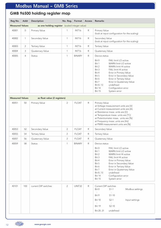
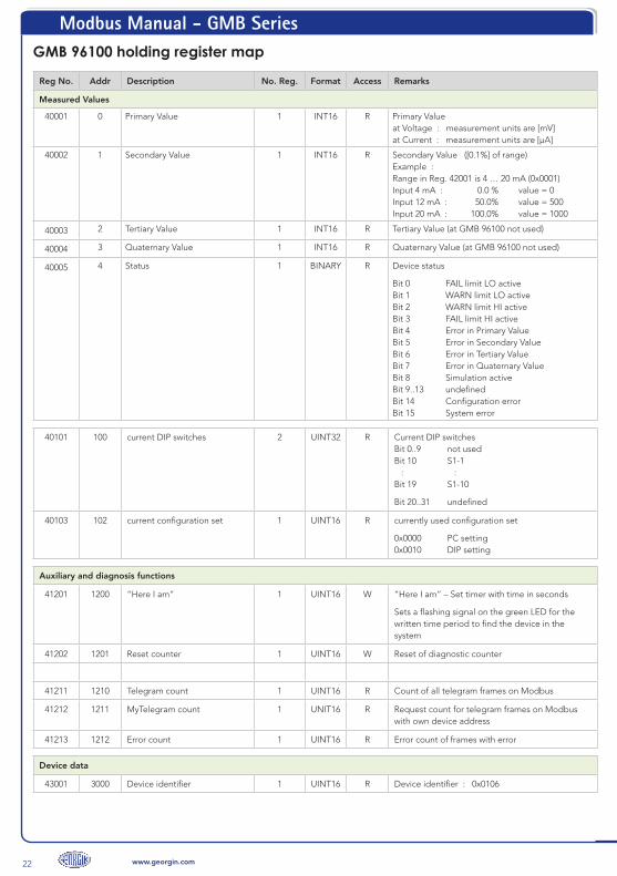
GMB 96500 holding register map
Reg No. Addr Description No. Reg. Format Access Remarks
Measured Values as one holding register (scaled integer value)
40001 0 Primary Value 1 INT16 R Primary Value (look at input configuration for the scaling)
40002 1 Secondary Value 1 INT16 R Secondary Value (look at input configuration for the scaling)
40003 2 Tertiary Value 1 INT16 R Tertiary Value
40004 3 Quaternary Value 1 INT16 R Quaternary Value
40005 4 Status 1 BINARY R Device status
Bit 0 FAIL limit LO active Bit 1 WARN limit LO active Bit 2 WARN limit HI active Bit 3 FAIL limit HI active Bit 4 Error in Primary Value Bit 5 Error in Secondary Value Bit 6 Error in Tertiary Value Bit 7 Error in Quaternary Value Bit 8..13 undefined Bit 14 Configuration error Bit 15 System error
Measured Values as float value (2 registers)
40051 50 Primary Value 2 FLOAT R Primary Value at Voltage measurement units are [V] at Current measurement units are [A] at Resistance meas. units are [Ω] at Temperature meas. units are [°C] at Potentiometer meas. units are [%] at Frequency meas. units are [Hz] at PWM measurement units are [%]
40053 52 Secondary Value 2 FLOAT R Secondary Value
40055 54 Tertiary Value 2 FLOAT R Tertiary Value
40057 56 Quaternary Value 2 FLOAT R Quaternary Value
40059 58 Status 1 BINARY R Device status
Bit 0 FAIL limit LO active Bit 1 WARN limit LO active Bit 2 WARN limit HI active Bit 3 FAIL limit HI active Bit 4 Error in Primary Value Bit 5 Error in Secondary Value Bit 6 Error in Tertiary Value Bit 7 Error in Quaternary Value Bit 8..13 undefined Bit 14 Configuration error Bit 15 System error
40101 100 current DIP switches 2 UINT32 R Current DIP switches Bit 0 S1-1 Modbus settings : : Bit 9 S1-10
Bit 10 S2-1 Input settings : : Bit 19 S2-10
Bit 20..31 undefined
Modbus Manual - GMB Series
13www.georgin.com
Reg No. Addr Description No. Reg. Format Access Remarks
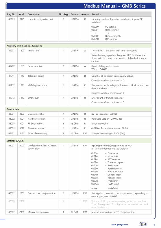
40103 102 current configuration set 1 UINT16 R currently used configuration set depending on DIP switches
0x0000 PC setting 0x0001 User setting 1 : : 0x000F User setting 15 0x0010 DIP setting
Auxiliary and diagnosis functions
41201 1200 “Here I am” 1 UINT16 W “Here I am” – Set timer with time in seconds
Sets a flashing signal on the green LED for the written time period to detect the position of the device in the cabinet
41202 1201 Reset counter 1 UINT16 W Reset of diagnostic counter Write : 0x0000
41211 1210 Telegram count 1 UINT16 R Count of all telegram frames on Modbus
Counter overflow continues at 0
41212 1211 MyTelegram count 1 UNIT16 R Request count for telegram frames on Modbus with own device address
Counter overflow continues at 0
41213 1212 Error count 1 UINT16 R Error count of frames with error
Counter overflow continues at 0
Device data
43001 3000 Device identifier 1 UINT16 R Device identifier : 0x0006
43002 3001 Hardware version 1 UINT16 R Hardware version : 0x0042 (B)
43005 3004 RFID identifier 8 16 Char R Unique identifier
43029 3028 Firmware version 1 UINT16 R 0x0100 – Example for version 01.0.0
45151 5150 Point of measuring 8 16 Char RW Point of measuring in ASCII (Tag)
Settings (CONF)
42001 2000 Configuration Set : PC mode sensor type
1 UINT16 RW Input type setting (programmed by PC) for further informations see table 01
0x00xx – Pt sensors 0x01xx – Ni sensors 0x02xx – KTY sensors 0x03xx – Thermocouples 0x04xx – Resistance 0x05xx – Potentiometer 0x06xx – mV shunt input 0x07xx – Current input 0x08xx – Voltage input 0x09xx – Frequency 0x0Axx – PWM input
other : undefined
42002 2001 Connection, compensation 1 UINT16 RW Settings for connection or compensation depending on sensor type, see table 02
42003 2002 4 RW Returns NULL bytes when reading, write has no effect. Thus, the registers of configuration set can be read and write in a block.
42007 2006 Manual temperature 2 FLOAT RW Manual temperature for TC compensation
Modbus Manual - GMB Series
14 www.georgin.com
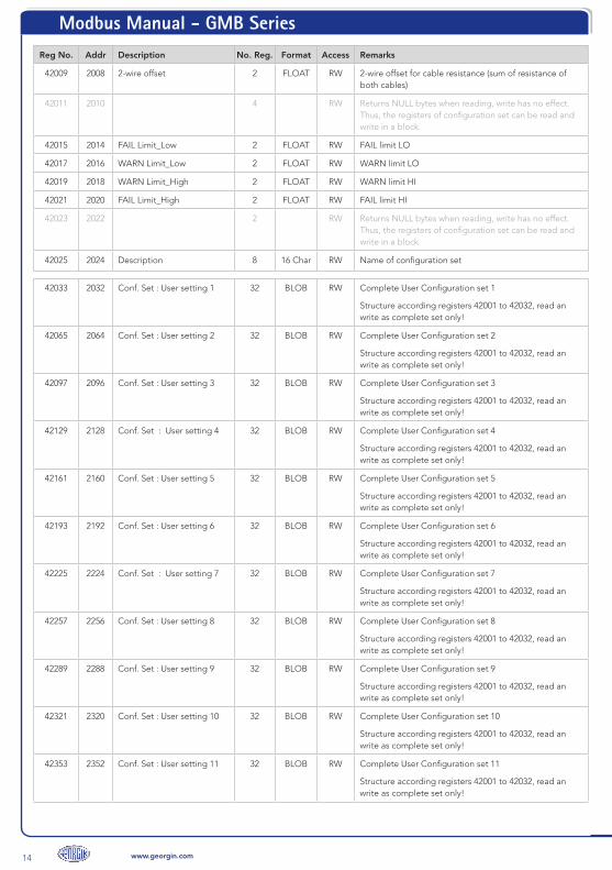
Reg No. Addr Description No. Reg. Format Access Remarks
42009 2008 2-wire offset 2 FLOAT RW 2-wire offset for cable resistance (sum of resistance of both cables)
42011 2010 4 RW Returns NULL bytes when reading, write has no effect. Thus, the registers of configuration set can be read and write in a block.
42015 2014 FAIL Limit_Low 2 FLOAT RW FAIL limit LO
42017 2016 WARN Limit_Low 2 FLOAT RW WARN limit LO
42019 2018 WARN Limit_High 2 FLOAT RW WARN limit HI
42021 2020 FAIL Limit_High 2 FLOAT RW FAIL limit HI
42023 2022 2 RW Returns NULL bytes when reading, write has no effect. Thus, the registers of configuration set can be read and write in a block.
42025 2024 Description 8 16 Char RW Name of configuration set
42033 2032 Conf. Set : User setting 1 32 BLOB RW Complete User Configuration set 1
Structure according registers 42001 to 42032, read an write as complete set only!
42065 2064 Conf. Set : User setting 2 32 BLOB RW Complete User Configuration set 2
Structure according registers 42001 to 42032, read an write as complete set only!
42097 2096 Conf. Set : User setting 3 32 BLOB RW Complete User Configuration set 3
Structure according registers 42001 to 42032, read an write as complete set only!
42129 2128 Conf. Set : User setting 4 32 BLOB RW Complete User Configuration set 4
Structure according registers 42001 to 42032, read an write as complete set only!
42161 2160 Conf. Set : User setting 5 32 BLOB RW Complete User Configuration set 5
Structure according registers 42001 to 42032, read an write as complete set only!
42193 2192 Conf. Set : User setting 6 32 BLOB RW Complete User Configuration set 6
Structure according registers 42001 to 42032, read an write as complete set only!
42225 2224 Conf. Set : User setting 7 32 BLOB RW Complete User Configuration set 7
Structure according registers 42001 to 42032, read an write as complete set only!
42257 2256 Conf. Set : User setting 8 32 BLOB RW Complete User Configuration set 8
Structure according registers 42001 to 42032, read an write as complete set only!
42289 2288 Conf. Set : User setting 9 32 BLOB RW Complete User Configuration set 9
Structure according registers 42001 to 42032, read an write as complete set only!
42321 2320 Conf. Set : User setting 10 32 BLOB RW Complete User Configuration set 10
Structure according registers 42001 to 42032, read an write as complete set only!
42353 2352 Conf. Set : User setting 11 32 BLOB RW Complete User Configuration set 11
Structure according registers 42001 to 42032, read an write as complete set only!

Modbus Manual - GMB Series
15www.georgin.com
Reg No. Addr Description No. Reg. Format Access Remarks
42385 2384 Conf. Set : User setting 12 32 BLOB RW Complete User Configuration set 12 Structure according registers 42001 to 42032, read an write as complete set only!
42417 2416 Conf. Set : User setting 13 32 BLOB RW Complete User Configuration set 13
Structure according registers 42001 to 42032, read an write as complete set only!
42449 2448 Conf. Set : User setting 14 32 BLOB RW Complete User Configuration set 14
Structure according registers 42001 to 42032, read an write as complete set only!
42481 2480 Conf. Set : User setting 15 32 BLOB RW Complete User Configuration set 15
Structure according registers 42001 to 42032, read an write as complete set only!
42513 2512 Conf. Set : DIP mode sen-sor type
1 UINT16 R Input type setting (programmed by PC) for further informations see table 01
0x00xx – Pt sensors 0x01xx – Ni sensors 0x02xx – KTY sensors 0x03xx – Thermocouples 0x04xx – Resistance 0x05xx – Potentiometer 0x06xx – mV shunt input 0x07xx – Current input 0x08xx – Voltage input 0x09xx – Frequency 0x0Axx – PWM input
other : undefined
42514 2513 Connection, compensation 1 UINT16 R Settings for connection or compensation depending on sensor type, see table 02
42537 2536 Description 8 16 Char R Name of configuration set
45001 5000 Configuration counter 1 UINT16 R Counter is incremented internally each write of Conf parameters.
The Modbus master can remember this value. As long as the counter has the same value, the configuration is unchanged.
45002 5001 Register order 1 UINT16 RW Order of registers at LONG or FLOAT values
<> 0 - HH-HL-LH-LL (default) == 0 - LH-LL-HH-HL
45003 5002 Date of last modification 2 UINT32 RW Date (UNIX_TIMESTAMP) last change (Not managed by the device)
45005 5004 Overrange at error 1 UINT16 RW Overrange at measuring error
0x0000 OFF (User must check
statusbits) 0x0001 ON (default)
45010 5009 Modbus : Address (in PC Mode)
1 UINT16 RW Modbus address : 1 … 247 (default = 1)

Modbus Manual - GMB Series
16 www.georgin.com
Reg No. Addr Description No. Reg. Format Access Remarks
45011 5010 Baud rate (in PC Mode)
1 UINT16 RW Baud rate : 0x0000 - 300 0x0001 - 600 0x0002 - 1200 0x0003 - 2400 0x0004 - 4800 0x0005 - 9600 0x0006 - 19200 (default) 0x0007 - 38400 0x0008 - 57600 0x0009 - 115200
other : undefined
45012 5011 Parity/Stop bits (in PC Mode)
1 UINT16 RW Parity :
0x0000 - Even, 1 Stop bit (default) 0x0001 - Odd, 1 Stop bit 0x0002 - None, 2 Stop bits 0x0003 - None, 1 Stop bit (no Spec!) (from Firmware 01.4.0)
other : undefined
45013 5012 Response delay (in PC Mode)
1 UINT16 RW Delay : 1 … 1000 ms (default = 1)
45020 5019 Modbus : Address (in DIP Mode)
1 UINT16 R Modbus address : 1 … 127
45021 5020 Baud rate (in DIP Mode)
1 UINT16 R Baud rate :
0x0005 - 9600 0x0006 - 19200 0x0007 - 38400 0x0009 - 115200
45022 5021 Parity/Stop bits (in DIP Mode)
1 UINT16 R Parity :
0x0000 - Even, 1 Stop bit 0x0002 - None, 2 Stop bits
45023 5022 Response delay (in DIP Mode)
1 UINT16 R Delay : 1 ms at 115200 Baud 3 ms at 38400 Baud 5 ms at 19200 Baud 10 ms at 9600 Baud
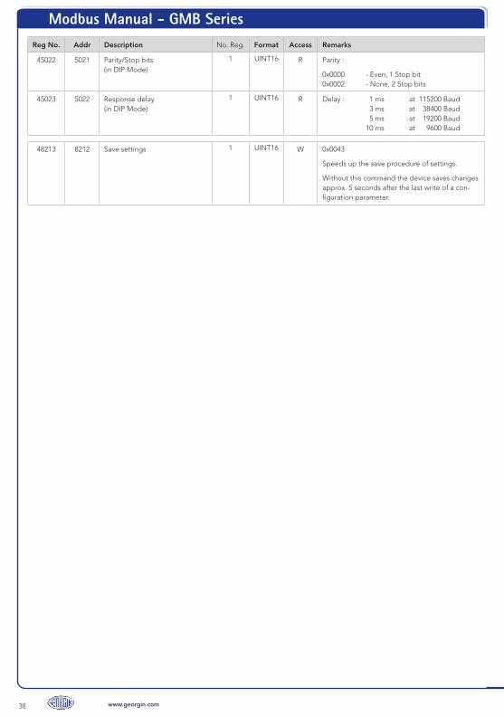
48213 8212 Save settings 1 UINT16 W 0x0043
Speeds up the save procedure of settings.
Without this command the device saves changes ap-prox. 5 seconds after the last write of a configuration parameter.
Modbus Manual - GMB Series
17www.georgin.com
Appendix
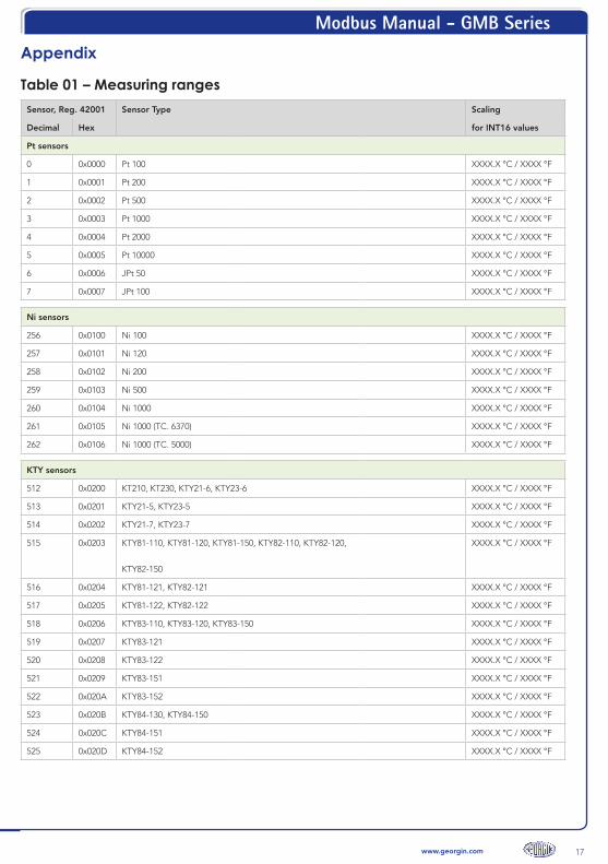
Table 01 – Measuring rangesSensor, Reg. 42001 Sensor Type Scaling
Decimal Hex for INT16 values
Pt sensors
0 0x0000 Pt 100 XXXX.X °C / XXXX °F
1 0x0001 Pt 200 XXXX.X °C / XXXX °F
2 0x0002 Pt 500 XXXX.X °C / XXXX °F
3 0x0003 Pt 1000 XXXX.X °C / XXXX °F
4 0x0004 Pt 2000 XXXX.X °C / XXXX °F
5 0x0005 Pt 10000 XXXX.X °C / XXXX °F
6 0x0006 JPt 50 XXXX.X °C / XXXX °F
7 0x0007 JPt 100 XXXX.X °C / XXXX °F
Ni sensors
256 0x0100 Ni 100 XXXX.X °C / XXXX °F
257 0x0101 Ni 120 XXXX.X °C / XXXX °F
258 0x0102 Ni 200 XXXX.X °C / XXXX °F
259 0x0103 Ni 500 XXXX.X °C / XXXX °F
260 0x0104 Ni 1000 XXXX.X °C / XXXX °F
261 0x0105 Ni 1000 (TC. 6370) XXXX.X °C / XXXX °F
262 0x0106 Ni 1000 (TC. 5000) XXXX.X °C / XXXX °F
KTY sensors
512 0x0200 KT210, KT230, KTY21-6, KTY23-6 XXXX.X °C / XXXX °F
513 0x0201 KTY21-5, KTY23-5 XXXX.X °C / XXXX °F
514 0x0202 KTY21-7, KTY23-7 XXXX.X °C / XXXX °F
515 0x0203 KTY81-110, KTY81-120, KTY81-150, KTY82-110, KTY82-120,
KTY82-150
XXXX.X °C / XXXX °F
516 0x0204 KTY81-121, KTY82-121 XXXX.X °C / XXXX °F
517 0x0205 KTY81-122, KTY82-122 XXXX.X °C / XXXX °F
518 0x0206 KTY83-110, KTY83-120, KTY83-150 XXXX.X °C / XXXX °F
519 0x0207 KTY83-121 XXXX.X °C / XXXX °F
520 0x0208 KTY83-122 XXXX.X °C / XXXX °F
521 0x0209 KTY83-151 XXXX.X °C / XXXX °F
522 0x020A KTY83-152 XXXX.X °C / XXXX °F
523 0x020B KTY84-130, KTY84-150 XXXX.X °C / XXXX °F
524 0x020C KTY84-151 XXXX.X °C / XXXX °F
525 0x020D KTY84-152 XXXX.X °C / XXXX °F
Modbus Manual - GMB Series
18 www.georgin.com
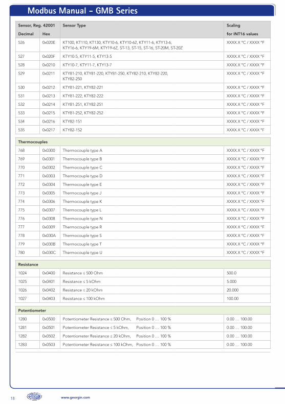
Sensor, Reg. 42001 Sensor Type Scaling
Decimal Hex for INT16 values
526 0x020E KT100, KT110, KT130, KTY10-6, KTY10-62, KTY11-6, KTY13-6, KTY16-6, KTY19-6M, KTY19-6Z, ST-13, ST-15, ST-16, ST-20M, ST-20Z
XXXX.X °C / XXXX °F
527 0x020F KTY10-5, KTY11-5, KTY13-5 XXXX.X °C / XXXX °F
528 0x0210 KTY10-7, KTY11-7, KTY13-7 XXXX.X °C / XXXX °F
529 0x0211 KTY81-210, KTY81-220, KTY81-250, KTY82-210, KTY82-220, KTY82-250
XXXX.X °C / XXXX °F
530 0x0212 KTY81-221, KTY82-221 XXXX.X °C / XXXX °F
531 0x0213 KTY81-222, KTY82-222 XXXX.X °C / XXXX °F
532 0x0214 KTY81-251, KTY82-251 XXXX.X °C / XXXX °F
533 0x0215 KTY81-252, KTY82-252 XXXX.X °C / XXXX °F
534 0x0216 KTY82-151 XXXX.X °C / XXXX °F
535 0x0217 KTY82-152 XXXX.X °C / XXXX °F
Thermocouples
768 0x0300 Thermocouple type A XXXX.X °C / XXXX °F
769 0x0301 Thermocouple type B XXXX.X °C / XXXX °F
770 0x0302 Thermocouple type C XXXX.X °C / XXXX °F
771 0x0303 Thermocouple type D XXXX.X °C / XXXX °F
772 0x0304 Thermocouple type E XXXX.X °C / XXXX °F
773 0x0305 Thermocouple type J XXXX.X °C / XXXX °F
774 0x0306 Thermocouple type K XXXX.X °C / XXXX °F
775 0x0307 Thermocouple type L XXXX.X °C / XXXX °F
776 0x0308 Thermocouple type N XXXX.X °C / XXXX °F
777 0x0309 Thermocouple type R XXXX.X °C / XXXX °F
778 0x030A Thermocouple type S XXXX.X °C / XXXX °F
779 0x030B Thermocouple type T XXXX.X °C / XXXX °F
780 0x030C Thermocouple type U XXXX.X °C / XXXX °F
Resistance
1024 0x0400 Resistance ≤ 500 Ohm 500.0
1025 0x0401 Resistance ≤ 5 kOhm 5.000
1026 0x0402 Resistance ≤ 20 kOhm 20.000
1027 0x0403 Resistance ≤ 100 kOhm 100.00
Potentiometer
1280 0x0500 Potentiometer Resistance ≤ 500 Ohm, Position 0 … 100 % 0.00 … 100.00
1281 0x0501 Potentiometer Resistance ≤ 5 kOhm, Position 0 … 100 % 0.00 … 100.00
1282 0x0502 Potentiometer Resistance ≤ 20 kOhm, Position 0 … 100 % 0.00 … 100.00
1283 0x0503 Potentiometer Resistance ≤ 100 kOhm, Position 0 … 100 % 0.00 … 100.00
Modbus Manual - GMB Series
19www.georgin.com
Sensor, Reg. 42001 Sensor Type Scaling
Decimal Hex for INT16 values
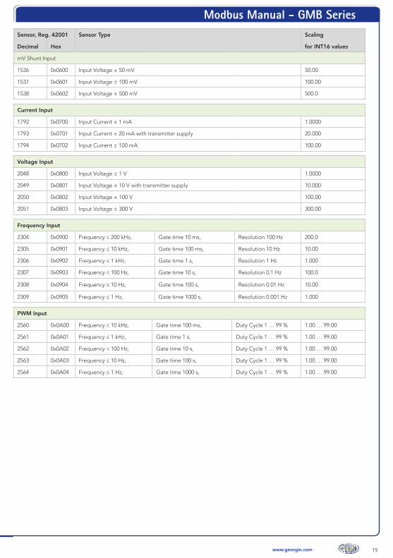
mV Shunt Input
1536 0x0600 Input Voltage ± 50 mV 50.00
1537 0x0601 Input Voltage ± 100 mV 100.00
1538 0x0602 Input Voltage ± 500 mV 500.0
Current Input
1792 0x0700 Input Current ± 1 mA 1.0000
1793 0x0701 Input Current ± 20 mA with transmitter supply 20.000
1794 0x0702 Input Current ± 100 mA 100.00
Voltage Input
2048 0x0800 Input Voltage ± 1 V 1.0000
2049 0x0801 Input Voltage ± 10 V with transmitter supply 10.000
2050 0x0802 Input Voltage ± 100 V 100.00
2051 0x0803 Input Voltage ± 300 V 300.00
Frequency Input
2304 0x0900 Frequency ≤ 200 kHz, Gate time 10 ms, Resolution 100 Hz 200.0
2305 0x0901 Frequency ≤ 10 kHz, Gate time 100 ms, Resolution 10 Hz 10.00
2306 0x0902 Frequency ≤ 1 kHz, Gate time 1 s, Resolution 1 Hz 1.000
2307 0x0903 Frequency ≤ 100 Hz, Gate time 10 s, Resolution 0.1 Hz 100.0
2308 0x0904 Frequency ≤ 10 Hz, Gate time 100 s, Resolution 0.01 Hz 10.00
2309 0x0905 Frequency ≤ 1 Hz, Gate time 1000 s, Resolution 0.001 Hz 1.000
PWM Input
2560 0x0A00 Frequency ≤ 10 kHz, Gate time 100 ms, Duty Cycle 1 … 99 % 1.00 … 99.00
2561 0x0A01 Frequency ≤ 1 kHz, Gate time 1 s, Duty Cycle 1 … 99 % 1.00 … 99.00
2562 0x0A02 Frequency ≤ 100 Hz, Gate time 10 s, Duty Cycle 1 … 99 % 1.00 … 99.00
2563 0x0A03 Frequency ≤ 10 Hz, Gate time 100 s, Duty Cycle 1 … 99 % 1.00 … 99.00
2564 0x0A04 Frequency ≤ 1 Hz, Gate time 1000 s, Duty Cycle 1 … 99 % 1.00 … 99.00

Modbus Manual - GMB Series
20 www.georgin.com
Table 02 – Connection / Compensation
Reg. 42002RTD / Poti TC CJC U / I F / PWM
Decimal Hex
0 0x0000 4-wire intern DC NAMUR Contact
1 0x0001 3-wire ext. Pt100 2-wire AC AVG (fast) SN / Contact
2 0x0002 2-wire ext. Pt100 3-wire AC AVG (normal) S0
3 0x0003 ext. Pt1000 2-wire AC AVG (slow) PNP
4 0x0004 ext. Pt1000 3-wire AC RMS (fast) NPN
5 0x0005 OFF AC RMS (normal) 5 V Logic + TX
6 0x0006 AC RMS (slow)
7 0x0007

Modbus Manual - GMB Series
21www.georgin.com
GMB 96100 Standard Signal AI Module
Precise capture of industrial standard signals Input
Excellent EMC performance and noise suppression 0/4 … 20 mA0/2 … 10 V0/1 … 5 V16 V Transmitter Supply
Supply of 2/3-wire transmitters
Easy configuration, fast commissioningMaximum reliability and durability
Supported communication features :
Baud rates : 300, 600, 1200, 2400, 4800, 9600, 19200, 38400, 57600, 115200
Formats : Parity even, 1 stop bit
Parity odd, 1 stop bit
Parity none, 2 stop bit
Parity none, 1 stop bit (not conform with specification !)
Factory setting : 19200 baud, 8 data bits, parity even, 1 stop bit, Modbus address 1
Supported function codes :
Command 3 : 0x03 Read Holding Register
Command 6 : 0x06 Write Single Register
Command 16 : 0x10 Write Multiple Register
Command 43 / 14 : 0x2B / 0x0E Read Device Identification
Note : Command 43, subcode 14 (Read Device Identification) supported in the "Basic" category to allow the device identification.
.
Modbus Manual - GMB Series
22 www.georgin.com
GMB 96100 holding register map
Reg No. Addr Description No. Reg. Format Access Remarks
Measured Values
40001 0 Primary Value 1 INT16 R Primary Value at Voltage : measurement units are [mV] at Current : measurement units are [µA]
40002 1 Secondary Value 1 INT16 R Secondary Value ([0.1%] of range) Example : Range in Reg. 42001 is 4 … 20 mA (0x0001) Input 4 mA : 0.0 % value = 0 Input 12 mA : 50.0% value = 500 Input 20 mA : 100.0% value = 1000
40003 2 Tertiary Value 1 INT16 R Tertiary Value (at GMB 96100 not used)
40004 3 Quaternary Value 1 INT16 R Quaternary Value (at GMB 96100 not used)
40005 4 Status 1 BINARY R Device status
Bit 0 FAIL limit LO active Bit 1 WARN limit LO active Bit 2 WARN limit HI active Bit 3 FAIL limit HI active Bit 4 Error in Primary Value Bit 5 Error in Secondary Value Bit 6 Error in Tertiary Value Bit 7 Error in Quaternary Value Bit 8 Simulation active Bit 9..13 undefined Bit 14 Configuration error Bit 15 System error
40101 100 current DIP switches 2 UINT32 R Current DIP switches Bit 0..9 not used Bit 10 S1-1 : : Bit 19 S1-10
Bit 20..31 undefined
40103 102 current configuration set 1 UINT16 R currently used configuration set
0x0000 PC setting 0x0010 DIP setting
Auxiliary and diagnosis functions
41201 1200 “Here I am” 1 UINT16 W “Here I am” – Set timer with time in seconds
Sets a flashing signal on the green LED for the written time period to find the device in the system
41202 1201 Reset counter 1 UINT16 W Reset of diagnostic counter
41211 1210 Telegram count 1 UINT16 R Count of all telegram frames on Modbus
41212 1211 MyTelegram count 1 UNIT16 R Request count for telegram frames on Modbus with own device address
41213 1212 Error count 1 UINT16 R Error count of frames with error
Device data
43001 3000 Device identifier 1 UINT16 R Device identifier : 0x0106

Modbus Manual - GMB Series
23www.georgin.com
Reg No. Addr Description No. Reg. Format Access Remarks
43002 3001 Hardware version 1 UINT16 R Hardware version : 0x0041 (A)
43005 3004 RFID identifier 8 16 Char R Unique identifier
43029 3028 Firmware version 1 UINT16 R 0x0100 – Example for version 01.0.0
45151 5150 Point of measuring 8 16 Char RW Point of measuring in ASCII (Tag)
Settings (CONF)
42001 2000 PC Mode 1 UINT16 RW Input type setting (programmed by PC)
0x0000 – 0 … 20 mA 0x0001 – 4 … 20 mA
0x0100 – 0 … 5/10 V (Auto range) 0x0101 – 0 … 10 V 0x0102 – 2 … 10 V 0x0103 – 0 … 5 V 0x0104 – 1 … 5 V
other : undefined
42003 2002 FAIL Limit_Low 1 INT16 RW FAIL limit LO
42004 2003 WARN Limit_Low 1 INT16 RW WARN limit LO
42005 2004 WARN Limit_High 1 INT16 RW WARN limit HI
42006 2005 FAIL Limit_High 1 INT16 RW FAIL limit HI
42513 2512 DIP Mode 1 UINT16 R Input type setting (DIP switches)
0x0000 – 0 … 20 mA
0x0100 – 0 … 10 V
other : undefined
45001 5000 Configuration counter 1 UINT16 R Counter is incremented internally each write of Conf parameters.
The Modbus master can remember this value. As long as the counter has the same value, the configuration is unchanged.
45002 5001 Register order 1 UINT16 RW Order of registers at LONG or FLOAT values
<> 0 - HH-HL-LH-LL (default) == 0 - LH-LL-HH-HL
45003 5002 Date of last modification 2 UINT32 RW Date (UNIX_TIMESTAMP) last change (Not managed by the device)
45010 5009 Modbus : Address (in PC Mode)
1 UINT16 RW Modbus address : 1 … 247 (default = 1)
45011 5010 Baud rate (in PC Mode)
1 UINT16 RW Baud rate : 0x0000 - 300 0x0001 - 600 0x0002 - 1200 0x0003 - 2400 0x0004 - 4800 0x0005 - 9600 0x0006 - 19200 (default) 0x0007 - 38400 0x0008 - 57600 0x0009 - 115200
other : undefined
Modbus Manual - GMB Series
24 www.georgin.com
Reg No. Addr Description No. Reg. Format Access Remarks
45012 5011 Parity/Stop bits (in PC Mode)
1 UINT16 RW Parity :
0x0000 - Even, 1 Stop bit (default) 0x0001 - Odd, 1 Stop bit 0x0002 - None, 2 Stop bits 0x0003 - None, 1 Stop bit (no Spec !) (from Firmware 01.4.0)
other : undefined
45013 5012 Response delay (in PC Mode)
1 UINT16 RW Delay : 1 … 1000 ms (default = 1)
45020 5019 Modbus : Address (in DIP Mode)
1 UINT16 R Modbus address : 1 … 63
45021 5020 Baud rate (in DIP Mode)
1 UINT16 R Baud rate :
0x0005 - 9600 0x0006 - 19200 0x0007 - 38400 0x0009 - 115200
45022 5021 Parity/Stop bits (in DIP Mode)
1 UINT16 R Parity :
0x0000 - Even, 1 Stop bit 0x0002 - None, 2 Stop bits
45023 5022 Response delay (in DIP Mode)
1 UINT16 R Delay : 1 ms at 115200 Baud 3 ms at 38400 Baud 5 ms at 19200 Baud 10 ms at 9600 Baud
48213 8212 Save settings 1 UINT16 W 0x0043
Speeds up the save procedure of settings.
Without this command the device saves changes approx. 5 seconds after the last write of a configu-ration parameter.
Modbus Manual - GMB Series
25www.georgin.com
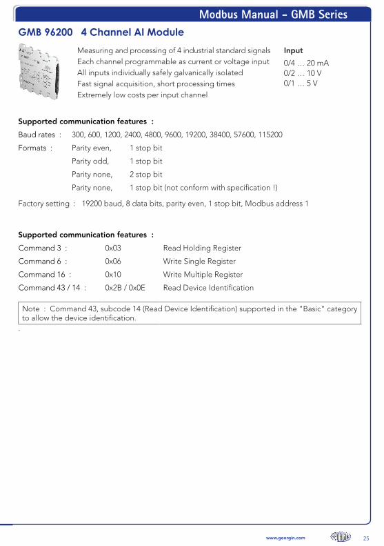
GMB 96200 4 Channel AI ModuleMeasuring and processing of 4 industrial standard signals InputEach channel programmable as current or voltage input 0/4 … 20 mA
0/2 … 10 V0/1 … 5 V
All inputs individually safely galvanically isolatedFast signal acquisition, short processing timesExtremely low costs per input channel
Supported communication features :
Baud rates : 300, 600, 1200, 2400, 4800, 9600, 19200, 38400, 57600, 115200
Formats : Parity even, 1 stop bit
Parity odd, 1 stop bit
Parity none, 2 stop bit
Parity none, 1 stop bit (not conform with specification !)
Factory setting : 19200 baud, 8 data bits, parity even, 1 stop bit, Modbus address 1
Supported communication features :
Command 3 : 0x03 Read Holding Register
Command 6 : 0x06 Write Single Register
Command 16 : 0x10 Write Multiple Register
Command 43 / 14 : 0x2B / 0x0E Read Device Identification
Note : Command 43, subcode 14 (Read Device Identification) supported in the "Basic" category to allow the device identification.
.

Modbus Manual - GMB Series
26 www.georgin.com
Coming soon...

Modbus Manual - GMB Series
27www.georgin.com
GMB 96700 4 Channel DI/DO Module4 independent controllable digital I/O channels Binary InputEach channel programmable as input or output 5 V / 12 V / 24 V
Binary, Frequency, Counter
Output
Extensive programmable operating functions
Universal Open-Collector output
Status indication for each I/O channel 30 V / 100 mABinary, Limit monitoring,Frequency, Pulse, PWM
Supported communication features :
Baud rates : 300, 600, 1200, 2400, 4800, 9600, 19200, 38400, 57600, 115200
Formats : Parity even, 1 stop bit
Parity odd, 1 stop bit
Parity none, 2 stop bit
Parity none, 1 stop bit (not conform with specification !)
Factory setting : 19200 baud, 8 data bits, parity even, 1 stop bit, Modbus address 1
Supported function codes :
Command 1 : 0x01 Read Coils
Command 2 : 0x02 Read Discrete Input
Command 3 : 0x03 Read Holding Register
Command 5 : 0x05 Write Single Coil
Command 6 : 0x06 Write Single Register
Command 15 : 0x0F Write Multiple Coils
Command 16 : 0x10 Write Multiple Register
Command 43 / 14 : 0x2B / 0x0E Read Device Identification
Note : Command 43, subcode 14 (Read Device Identification) supported in the "Basic" category to allow the device identification.
.
Modbus Manual - GMB Series
28 www.georgin.com
GMB 96700 Operating modes and examples
Operating modes with DIP switch settingsDIP switch S1-1 switches between 4x direct binary input and 4x direct binary output.With the DIP switches S1-2 and S1-3 the baud rate ist selected, with S1-4 the parity bit. The DIPswitches S1-5 to S1-10 defines the Modbus address of the device in range of 1 to 63. The Modbusaddress must be unique in the Modbus segment. For higher addresses you must use the PC mode(see below).
a. InputThe binary input signal sets the coils and the holding register 40011 bit as 0 or 1. The input level is detected for 24 V systems, it can be reconfigured to 5 V- or 12 V level systems.
b. OutputWrite coil or the holding register 40011 via Modbus. The output will direct follow to 0 or 1.
Operating modes with PC modeAll DIP switches must be OFF. Modbus address and all device parameters are set via the Modbusinterface or the front USB connector in the holding registers (see holding register map).1 The register addresses always refer to channel 1
a Binary input (switch input)
Holding register 420011 = 0x0000 (other channels : 421012/422013/423014)The input level is set in register 420021 for 5 V-, 12 V- or 24 V systems. The binary input signalsets the coils and the holding register 40011 bit as 0 or 1.
b Frequency input [Hz]
Holding register 420011 = 0x0001 (other channels : 421012/422013/423014)The input level is set in register 420021 for 5 V-, 12 V- or 24 V systems. The measured inputfrequency (up to 1 kHz) ist stored in the corresponding measured value registers. The updaterate of the measured values is the period duration of the input signal.In INT16 register 400011, the frequency is available with a resolution of 0.1 Hz (frequency x10) on the Modbus.In the FLOAT register 400511, the frequency is provided in [Hz] with decimal places for theModbus.
c Counter input [Counts]
Holding register 420011 = 0x0002 (other channels : 421012/422013/423014)The input level is set in register 420021 for 5 V-, 12 V- or 24 V systems. The rising edges of theinput signal are counted with a 32-bit counter. At counter overflow, the overflow bit assignedto the input is set in the measured value status register 40005/40059. The counter is reset tozero during the device start-up and at every configuration change !Using the holding register 40013, the counters can be reset via Modbus.The counter reading can be read as UINT32 in register 400511, status in register 40059. The counter can also be read as 16-bit counter UINT16 via register 400011, status in register40005.
d Binary output (switching output)
Holding register 420011 = 0x0010 (other channels : 421012/422013/423014)Write coil or the holding register 40011 via Modbus. The output will follow to 0 or 1, withcompliance with the output settings, such as min/max activation time and ON/OFF delay.
Modbus Manual - GMB Series
29www.georgin.com
e Binary output (INT16 limit monitoring)
Holding register 420011 = 0x0011 (other channels : 421012/422013/423014)The device monitors a 16-bit integer measured value, which is supplied via Modbus inregister 400011, to lower and higher limits. If the lower limit value in register 420181 isexceeded or the higher limit value in register 420191 is exceeded, the output of the channelis activated. To switch back to inactive output, the hysteresis in register 420201 must bepassed through. This can combined with the output settings, such as min/max activationtime and ON/OFF delay.Register 420181
Register 420191
Register 420201
INT16 limit lowINT16 limit highINT16 hysteresis
(–32768 to +32767, factory setting –1000)(–32768 to +32767, factory setting +1000)(3 to +32767, factory setting 10)
f Binary output (INT32 limit monitoring)
Holding register 420011 = 0x0012 (other channels : 421012/422013/423014)The device monitors a 32-bit integer measured value, which is supplied via Modbus inregister 400511, to lower and higher limits. If the lower limit value in register 420211 isexceeded or the higher limit value in register 420231 is exceeded, the output of the channelis activated. To switch back to inactive output, the hysteresis in register 420251 must bepassed through. This can combined with the output settings, such as min/max activationtime and ON/OFF delay.Register 420211
Register 420231
Register 420251
INT32 limit lowINT32 limit highINT32 hysteresis
g Binary output (FLOAT limit monitoring)
Holding register 420011 = 0x0013 (other channels : 421012/422013/423014)The device monitors a measured floating point value, which is supplied via Modbus in register 400511, to lower and higher limits. If the lower limit value in register 420211 is exceeded or the higher limit value in register 420231 is exceeded, the output of the channel is activated. To switch back to inactive output, the hysteresis in register 420251 must be passed through. This can combined with the output settings, such as min/max activation time and ON/OFF delay.Register 420211
Register 420231
Register 420251
FLOAT limit lowFLOAT limit highFLOAT hysteresis
(factory setting : Float –1000.0)(factory setting : Float +1000.0)(factory setting : Float 10.0)
h Frequency output [Hz]
Holding register 420011 = 0x0014 (other channels : 421012/422013/423014)The desired output frequency (0.1 ... 1000.0 Hz) is supplied by the Modbus in INT16 register400011 with a resolution of 0.1 Hz (frequency x10). The generated frequency at the outputterminal has a duty cycle of approximately 50 : 50.

Modbus Manual - GMB Series
30 www.georgin.com
i Pulse output [1/min]
Holding register 420011 = 0x0015 (other channels : 421012/422013/423014)The pulse output supplies a number of pulses (1 to 60000 / min) as an output signal. The pulse width can be set in register 420031. The max. Pulse width is a halv period. For a duty cycle 50 : 50, the pulse width must be programmed to 30000.The desired output value is supplied by Modbus in UINT16 register 400011.
j PWM output [%]
Holding register 420011 = 0x0016 (other channels : 421012/422013/423014)The PWM output converts the INT16 measured value transferred from Modbus to register400011 into a PWM signal with 500 Hz and a ratio between 10 % and 90 %. The inputresolution is 0.1 %.The scaling to the output is : 0.0 % (0) correspond to a ratio of 10%,100.0 % (1000) correspond to a ratio of 90%.
Output parameters
For all modes with binary output (binary output or limit monitoring), there are a variety ofparameters to comply all output requirements :
Register 420121
N/O (normally open)N/C (normally closed)
Contact typewith inactive output the output is open (factory setting)with inactive output the output is short-circuited (if device is powered !)
Register 420131 min. activation timeThe minimum activation time is the minimum duration of a output pulse, for example, whencontrolling a stepping motion switch, the output pulse must not be too short. The minimumactivation time is programmed in steps of [100 ms]. Factory setting is 0x0000.
Register 420141 max. activation timeThe maximum activation time is effective when the output is activated for a long time. For example,in order to avoid overloading valves, the maximum permissible operating time can be programmed in steps of [100 ms]. Factory setting is 0x0000.
Register 420151 ON delay
The response of the output to the input signal can be influenced by a ON delay. When activated atthe input, the output follows after the delay time. If the input is inactive during this time, the outputremains inactive. The output follows the input signal only after the ON delay has elapsed. The ONdelay can be used to tolerate short input pulses. The delay time is programmable in steps of [100 ms]. The factory setting is 0x0000 (no delay)..
Register 420161 OFF delayThe OFF delay prevents an immediate turn-off of the output when the input is inactive. The outputremains active for the programmed OFF delay. If the input is active again during this time, the delaytime starts again. The delay time is programmed in steps of [100 ms]. The factory setting is 0x0000(no delay).A special case is the value 0xFFFF, which activates the confirmation mode. In confirmation mode, the output remains active until an confirmation has been received. The confirmation request is signalized by a bit in the confirmation register 40012 and can be confirmed by writing to this register. The output becomes inactive after the confirmation, if the input is inactive.
Modbus Manual - GMB Series
31www.georgin.com
1 The specified register addresses apply to channel 1. At channel 2 : +100, channel 3 : +200 and channel 4 : +300
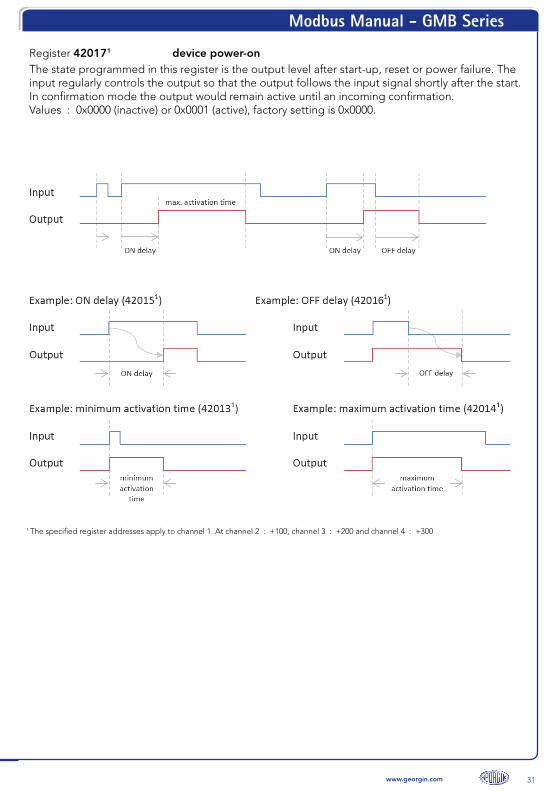
Register 420171 device power-onThe state programmed in this register is the output level after start-up, reset or power failure. Theinput regularly controls the output so that the output follows the input signal shortly after the start. In confirmation mode the output would remain active until an incoming confirmation.Values : 0x0000 (inactive) or 0x0001 (active), factory setting is 0x0000.

Modbus Manual - GMB Series
32 www.georgin.com
GMB 96700 coil mapCoil Addr Description Access Remarks
Measured Values
1 0 Input/Output 1 RW Binary signal at Input/ Output 1
2 1 Input/Output 2 RW Binary signal at Input/ Output 2
3 2 Input/Output 3 RW Binary signal at Input/ Output 3
4 3 Input/Output 4 RW Binary signal at Input/ Output 4
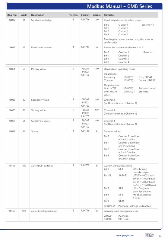
GMB 96700 holding register mapReg No. Addr Description No. Reg. Format Access Remarks
Inputs and outputs
40001 0 Primary Value 1 INT16 UINT16
RW Depends on operating mode
Input mode Frequency (0x0001) : Frequency x10 (1000.0 Hz) Counter (0x0002) : Counts UINT16
Output mode Limit INT16 (0x0011) : Set meas. value Frequency (0x0014) : Set Freq. x10 Pulse (0x0015) : Set pulse rate (1 - 60000 /min) PWM (0x0016) : Set duty cycle (0.0 - 100.0%)
40002 1 Secondary Value 1 INT16 UINT16
RW Channel 2 (for Description see Channel 1)
40003 2 Tertiary Value 1 INT16
UNIT16
RW Channel 3 (for Description see Channel 1)
40004 3 Quaternary Value 1 INT16
UINT16
RW Channel 4 (for Description see Channel 1)
40005 4 Status 1 UINT16 R Status of values
Bit 0 Counter 1 overflow or Limit 1 active Bit 1 Counter 2 overflow or Limit 2 active Bit 2 Counter 3 overflow or Limit 3 active Bit 3 Counter 4 overflow or Limit 4 active
40011 10 Input/Output direct 1 UINT16 RW Operation mode : binary signal
Bit 0 Input/Output 1 Bit 1 Input/Output 2 Bit 2 Input/Output 3 Bit 3 Input/Output 4
inactive = 0, active = 1
Output channels can have programmed opera-tion timing.
Modbus Manual - GMB Series
33www.georgin.com
Reg No. Addr Description No. Reg. Format Access Remarks
40012 11 Send acknowledge 1 UINT16 RW Reset output in confirmation mode
Bit 0 Output 1 confirm = 1 Bit 1 Output 2 Bit 2 Output 3 Bit 3 Output 4
Read register shows the outputs, who waits for confirmation
40013 12 Reset input counter 1 UINT16 W Resets the counter for channel 1 to 4
Bit 0 Counter 1 Reset = 1 Bit 1 Counter 2 Bit 2 Counter 3 Bit 3 Counter 4
40051 50 Primary Value 2 FLOAT INT32
UINT32
RW Depends on operating mode
Input mode Frequency (0x0001) : Freq. FLOAT Counter (0x0002) : Counts UINT32
Output mode Limit INT32 (0x0012) : Set meas. value Limit FLOAT (0x0013) : Set meas. value
40053 52 Secondary Value 2 FLOAT INT32
UINT32
RW Channel 2 (for Description see Channel 1)
40055 54 Tertiary Value 2 FLOAT INT32
UINT32
RW Channel 3 (for Description see Channel 1)
40057 56 Quaternary Value 2 FLOAT INT32
UINT32
RW Channel 4 (for Description see Channel 1)
40059 58 Status 1 UINT16 R Status of values
Bit 0 Counter 1 overflow or Limit 1 active Bit 1 Counter 2 overflow or Limit 2 active Bit 2 Counter 3 overflow or Limit 3 active Bit 3 Counter 4 overflow or Limit 4 active
40101 100 current DIP switches 2 UINT32 R Current DIP switch setting Bit 0 S1-1 off = 4x input on = 4x output Bit 1/2 S1-2/-3 off/off = 9600 baud off/on = 19200 baud on/off = 38400 baud on/on = 115200 baud Bit 3 S1-4 off = Parity even on = Parity none Bit 4 S1-5 Modbus address : : 1 to 63 Bit 9 S1-10
all DIPs off : PC mode, settings via Modbus
40103 102 current configuration set 1 UINT16 R currently used configuration set
0x0000 PC mode 0x0010 DIP mode

Modbus Manual - GMB Series
34 www.georgin.com
Reg No. Addr Description No. Reg. Format Access Remarks
Auxiliary and diagnosis functions
41201 1200 “Here I am” 1 UINT16 W “Here I am” – Set timer with time [s]
Sets a flashing signal on the green LED for the written timeperiod to easy find this device in the system
41202 1201 Reset counter 1 UINT16 W Reset of diagnostic counter
41211 1210 Telegram count 1 UINT16 R Count of all telegram frames on Modbus
41212 1211 MyTelegram count 1 UNIT16 R Request count for telegram frames on Modbus with own device address
41213 1212 Error count 1 UINT16 R Error count of frames with error
Device data
43001 3000 Device identifier 1 UINT16 R Device identifier : 0x0007
43002 3001 Hardware version 1 UINT16 R Hardware version : 0x0041 (A)
43005 3004 RFID identifier 8 16 Char R Unique identifier
43029 3028 Firmware version 1 UINT16 R 0x0100 – Example for version 01.0.0
45151 5150 Point of measuring 8 16 Char RW Point of measuring in ASCII (Tag)
Settings (CONF)
== Channel 1 ==
42001 2000 Operating mode channel 1 1 UINT16 RW Set the operating mode of channel 1
Input mode 0x0000 Binary signals 0x0001 Frequency measurement 0x0002 Counter input (32 bit counter) (Reset at Start / CONF changed)
Output mode 0x0010 Binary signals 0x0011 Limit monitoring INT16 0x0012 Limit monitoring INT32 0x0013 Limit monitoring FLOAT 0x0014 Frequency output [Hz] 0x0015 Pulse generation [1/min] 0x0016 PWM output, Freq. = 500 Hz
42002 2001 Input level 1 UINT16 RW Input level for channel 1 0x0000 5 V (<1.5 V >3.5 V) 0x0001 12 V (<2.0 V >8.4 V) 0x0002 24 V (<2.5 V >16.8 V)
42003 2002 Pulse width 1 UINT16 RW Pulse width at pulse output [ms] channel 1 min. pulse width (0x0000) = 300 µs
42012 2011 Contact type 1 UINT16 RW Contact type for channel 1 0x0000 N/O normally open 0x0001 N/C normally closed
42013 2012 min. activation time 1 UINT16 RW Minimal activation time [100 ms] channel 1 The output stays active minimal this time.
0x0000 Function off
42014 2013 max. activation time 1 UINT16 RW Maximal activation time [100 ms] channel 1 The active output ist limited to this time. Example : wiping contact
0x0000 Function off
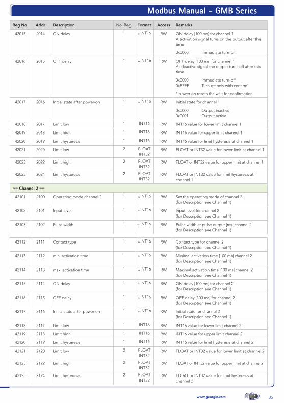
Modbus Manual - GMB Series
35www.georgin.com
Reg No. Addr Description No. Reg. Format Access Remarks
42015 2014 ON delay 1 UINT16 RW ON delay [100 ms] for channel 1 A activation signal turns on the output after this time
0x0000 Immediate turn-on
42016 2015 OFF delay 1 UINT16 RW OFF delay [100 ms] for channel 1 At deactive signal the output turns off after this time
0x0000 Immediate turn-off 0xFFFF Turn-off only with confirm*
* power-on resets the wait for confirmation
42017 2016 Initial state after power-on 1 UINT16 RW Initial state for channel 1
0x0000 Output inactive 0x0001 Output active
42018 2017 Limit low 1 INT16 RW INT16 value for lower limit channel 1
42019 2018 Limit high 1 INT16 RW INT16 value for upper limit channel 1
42020 2019 Limit hysteresis 1 INT16 RW INT16 value for limit hysteresis at channel 1
42021 2020 Limit low 2 FLOAT INT32
RW FLOAT or INT32 value for lower limit at channel 1
42023 2022 Limit high 2 FLOAT INT32
RW FLOAT or INT32 value for upper limit at channel 1
42025 2024 Limit hysteresis 2 FLOAT INT32
RW FLOAT or INT32 value for limit hysteresis at channel 1
== Channel 2 ==
42101 2100 Operating mode channel 2 1 UINT16 RW Set the operating mode of channel 2 (for Description see Channel 1)
42102 2101 Input level 1 UINT16 RW Input level for channel 2 (for Description see Channel 1)
42103 2102 Pulse width 1 UINT16 RW Pulse width at pulse output [ms] channel 2 (for Description see Channel 1)
42112 2111 Contact type 1 UINT16 RW Contact type for channel 2 (for Description see Channel 1)
42113 2112 min. activation time 1 UINT16 RW Minimal activation time [100 ms] channel 2 (for Description see Channel 1)
42114 2113 max. activation time 1 UINT16 RW Maximal activation time [100 ms] channel 2 (for Description see Channel 1)
42115 2114 ON delay 1 UINT16 RW ON delay [100 ms] for channel 2 (for Description see Channel 1)
42116 2115 OFF delay 1 UINT16 RW OFF delay [100 ms] for channel 2 (for Description see Channel 1)
42117 2116 Initial state after power-on 1 UINT16 RW Initial state for channel 2 (for Description see Channel 1)
42118 2117 Limit low 1 INT16 RW INT16 value for lower limit channel 2
42119 2118 Limit high 1 INT16 RW INT16 value for upper limit channel 2
42120 2119 Limit hysteresis 1 INT16 RW INT16 value for limit hysteresis at channel 2
42121 2120 Limit low 2 FLOAT INT32
RW FLOAT or INT32 value for lower limit at channel 2
42123 2122 Limit high 2 FLOAT INT32
RW FLOAT or INT32 value for upper limit at channel 2
42125 2124 Limit hysteresis 2 FLOAT INT32
RW FLOAT or INT32 value for limit hysteresis at channel 2

Modbus Manual - GMB Series
36 www.georgin.com
Reg No. Addr Description No. Reg. Format Access Remarks
== Channel 3 ==
42201 2200 Operating mode channel 3 1 UINT16 RW Set the operating mode of channel 3 (for Description see Channel 1)
42202 2201 Input level 1 UINT16 RW Input level for channel 3 (for Description see Channel 1)
42203 2202 Pulse width 1 UINT16 RW Pulse width at pulse output [ms] channel 3 (for Description see Channel 1)
42212 2211 Contact type 1 UINT16 RW Contact type for channel 3 (for Description see Channel 1)
42213 2212 min. activation time 1 UINT16 RW Minimal activation time [100 ms] channel 3 (for Description see Channel 1)
42214 2213 max. activation time 1 UINT16 RW Maximal activation time [100 ms] channel 3 (for Description see Channel 1)
42215 2214 ON delay 1 UINT16 RW ON delay [100 ms] for channel 3 (for Description see Channel 1)
42216 2215 OFF delay 1 UINT16 RW OFF delay [100 ms] for channel 3 (for Description see Channel 1)
42217 2216 Initial state after power-on 1 UINT16 RW Initial state for channel 3 (for Description see Channel 1)
42218 2217 Limit low 1 INT16 RW INT16 value for lower limit channel 3
42219 2218 Limit high 1 INT16 RW INT16 value for upper limit channel 3
42220 2219 Limit hysteresis 1 INT16 RW INT16 value for limit hysteresis at channel 3
42221 2220 Limit low 2 FLOAT INT32
RW FLOAT or INT32 value for lower limit at channel 3
42223 2222 Limit high 2 FLOAT INT32
RW FLOAT or INT32 value for upper limit at channel 3
42225 2224 Limit hysteresis 2 FLOAT INT32
RW FLOAT or INT32 value for limit hysteresis at channel 3
== Channel 4 ==
42301 2300 Operating mode channel 4 1 UINT16 RW Set the operating mode of channel 4 (for Description see Channel 1)
42302 2301 Input level 1 UINT16 RW Input level for channel 4 (for Description see Channel 1)
42303 2302 Pulse width 1 UINT16 RW Pulse width at pulse output [ms] channel 4 (for Description see Channel 1)
42312 2311 Contact type 1 UINT16 RW Contact type for channel 4 (for Description see Channel 1)
42313 2312 min. activation time 1 UINT16 RW Minimal activation time [100 ms] channel 4 (for Description see Channel 1)
42314 2313 max. activation time 1 UINT16 RW Maximal activation time [100 ms] channel 4 (for Description see Channel 1)
42315 2314 ON delay 1 UINT16 RW ON delay [100 ms] for channel 4 (for Description see Channel 1)
42316 2315 OFF delay 1 UINT16 RW OFF delay [100 ms] for channel 4 (for Description see Channel 1)
42317 2316 Initial state after power-on 1 UINT16 RW Initial state for channel 4 (for Description see Channel 1)
42318 2317 Limit low 1 INT16 RW INT16 value for lower limit channel 4

Modbus Manual - GMB Series
37www.georgin.com
Reg No. Addr Description No. Reg. Format Access Remarks
42319 2318 Limit high 1 INT16 RW INT16 value for upper limit channel 4
42320 2319 Limit hysteresis 1 INT16 RW INT16 value for limit hysteresis at channel 4
42321 2320 Limit low 2 FLOAT INT32
RW FLOAT or INT32 value for lower limit at channel 4
42323 2322 Limit high 2 FLOAT INT32
RW FLOAT or INT32 value for upper limit at channel 4
42325 2324 Limit hysteresis 2 FLOAT INT32
RW FLOAT or INT32 value for limit hysteresis at channel 4
45001 5000 Configuration counter 1 UINT16 R Counter is incremented internally each write of Conf parameters.
The Modbus master can remember this value. As long as the counter has the same value, the configuration is unchanged.
45002 5001 Register order 1 UINT16 RW Order of registers at INT32 or FLOAT values
0x0001 HH-HL-LH-LL (default) 0x0000 LH-LL-HH-HL
45003 5002 Date of last modification 2 UINT32 RW Date (UNIX_TIMESTAMP) last change (Not managed by the device)
45010 5009 Modbus : Address (in PC Mode)
1 UINT16 RW Modbus address : 1 … 247 (default = 1)
45011 5010 Baud rate (in PC Mode)
1 UINT16 RW Baud rate : 0x0000 - 300 0x0001 - 600 0x0002 - 1200 0x0003 - 2400 0x0004 - 4800 0x0005 - 9600 0x0006 - 19200 (default) 0x0007 - 38400 0x0008 - 57600 0x0009 - 115200
other : undefined
45012 5011 Parity/Stop bits (in PC Mode)
1 UINT16 RW Parity :
0x0000 - Even, 1 Stop bit (default) 0x0001 - Odd, 1 Stop bit 0x0002 - None, 2 Stop bits 0x0003 - None, 1 Stop bit (no Spec !) (from Firmware 01.4.0)
other : undefined
45013 5012 Response delay (in PC Mode)
1 UINT16 RW Delay : 1 … 1000 ms (default = 1)
45020 5019 Modbus : Address (in DIP Mode)
1 UINT16 R Modbus address : 1 … 63
45021 5020 Baud rate (in DIP Mode)
1 UINT16 R Baud rate :
0x0005 - 9600 0x0006 - 19200 0x0007 - 38400 0x0009 - 115200
Modbus Manual - GMB Series
38 www.georgin.com
Reg No. Addr Description No. Reg. Format Access Remarks
45022 5021 Parity/Stop bits (in DIP Mode)
1 UINT16 R Parity :
0x0000 - Even, 1 Stop bit 0x0002 - None, 2 Stop bits
45023 5022 Response delay (in DIP Mode)
1 UINT16 R Delay : 1 ms at 115200 Baud 3 ms at 38400 Baud 5 ms at 19200 Baud 10 ms at 9600 Baud
48213 8212 Save settings 1 UINT16 W 0x0043
Speeds up the save procedure of settings.
Without this command the device saves changes approx. 5 seconds after the last write of a con-figuration parameter.
Modbus Manual - GMB Series
39www.georgin.com
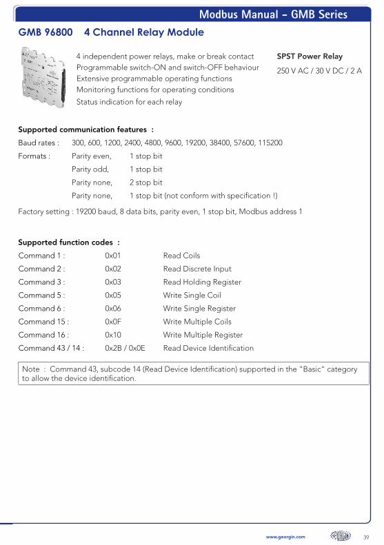
GMB 96800 4 Channel Relay Module
4 independent power relays, make or break contact SPST Power RelayProgrammable switch-ON and switch-OFF behaviour 250 V AC / 30 V DC / 2 AExtensive programmable operating functionsMonitoring functions for operating conditions
Status indication for each relay
Supported communication features :
Baud rates : 300, 600, 1200, 2400, 4800, 9600, 19200, 38400, 57600, 115200
Formats : Parity even, 1 stop bit
Parity odd, 1 stop bit
Parity none, 2 stop bit
Parity none, 1 stop bit (not conform with specification !)
Factory setting : 19200 baud, 8 data bits, parity even, 1 stop bit, Modbus address 1
Supported function codes :
Command 1 : 0x01 Read Coils
Command 2 : 0x02 Read Discrete Input
Command 3 : 0x03 Read Holding Register
Command 5 : 0x05 Write Single Coil
Command 6 : 0x06 Write Single Register
Command 15 : 0x0F Write Multiple Coils
Command 16 : 0x10 Write Multiple Register
Command 43 / 14 : 0x2B / 0x0E Read Device Identification
Note : Command 43, subcode 14 (Read Device Identification) supported in the "Basic" category to allow the device identification.
Modbus Manual - GMB Series
40 www.georgin.com
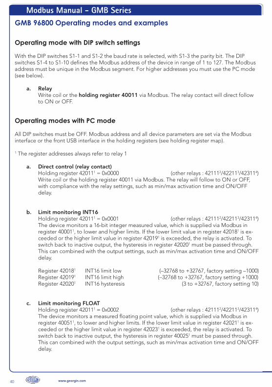
GMB 96800 Operating modes and examples
Operating mode with DIP switch settings
With the DIP switches S1-1 and S1-2 the baud rate is selected, with S1-3 the parity bit. The DIP switches S1-4 to S1-10 defines the Modbus address of the device in range of 1 to 127. The Modbus address must be unique in the Modbus segment. For higher addresses you must use the PC mode (see below).
a. Relay Write coil or the holding register 40011 via Modbus. The relay contact will direct follow to ON or OFF.
Operating modes with PC mode
All DIP switches must be OFF. Modbus address and all device parameters are set via the Modbus interface or the front USB interface in the holding registers (see holding register map).
1 The register addresses always refer to relay 1
a. Direct control (relay contact) Holding register 420111 = 0x0000 (other relays : 421112/422113/423114) Write coil or the holding register 40011 via Modbus. The relay will follow to ON or OFF, with compliance with the relay settings, such as min/max activation time and ON/OFF delay.
b. Limit monitoring INT16 Holding register 420111 = 0x0001 (other relays : 421112/422113/423114) The device monitors a 16-bit integer measured value, which is supplied via Modbus in register 400011, to lower and higher limits. If the lower limit value in register 420181 is ex-ceeded or the higher limit value in register 420191 is exceeded, the relay is activated. To switch back to inactive output, the hysteresis in register 420201 must be passed through. This can combined with the output settings, such as min/max activation time and ON/OFF delay. Register 420181 INT16 limit low (–32768 to +32767, factory setting –1000) Register 420191 INT16 limit high (–32768 to +32767, factory setting +1000) Register 420201 INT16 hysteresis (3 to +32767, factory setting 10)
c. Limit monitoring FLOAT Holding register 420111 = 0x0002 (other relays : 421112/422113/423114) The device monitors a measured floating point value, which is supplied via Modbus in register 400511, to lower and higher limits. If the lower limit value in register 420211 is ex-ceeded or the higher limit value in register 420231 is exceeded, the relay is activated. To switch back to inactive output, the hysteresis in register 400251 must be passed through. This can combined with the output settings, such as min/max activation time and ON/OFF delay.
Modbus Manual - GMB Series
41www.georgin.com
Register 420211 FLOAT limit low (factory setting : Float –1000.0) Register 420231 FLOAT limit high (factory setting : Float +1000.0) Register 420251 FLOAT hysteresis (factory setting : Float 10.0)
d. Limit monitoring INT16 (relay 1) Holding register 420112 = 0x0003 (other relays : 422113/423114) Is identical as for limit monitoring INT16 (b), except that the measured value of channel 1 is used for the comparison. It is possible to control several relays as min and max contacts from one measured value in register 40001.
e. Limit monitoring FLOAT (relay 1) Holding register 420112 = 0x0004 (other relays : 422113/423114) Is identical as for limit monitoring FLOAT (c), except that the measured value of channel 1 is used for the comparison. It is possible to control several relays as min and max contacts from one measured value in register 40051.
f. Monitoring of power supply Holding register 420111 = 0x0005 (other relays : 421112/422113/423114) Limit value monitoring of the supply voltage to lower and higher limits. If the lower limit value in register 420181 is exceeded or the higher limit value in register 420191 is exceeded, the relay is activated. To switch back to inactive output, the hysteresis in register 420201 must be passed through. This can combined with the compliance with the relay settings, such as min/max activation time and ON/OFF delay. Register 420181 Power supply limit low in [0.1 V] resolution Register 420191 Power supply limit high in [0.1 V] resolution Register 420201 Power supply hysteresis in [0.1 V] resolution
Relay parameters
For all modes, there are a variety of parameters to comply all relay contact requirements :
Register 420121 Contact type N/O (normally open) with inactive relay the contact is open (factory setting) N/C (normally closed) with inactive relay the contact is short-circuited
Register 420131 min. activation time The minimum activation time is the minimum duration of a short output pulse, for example, when controlling a stepping motion switch, the output pulse must not be too short. The minimum activa-tion time is programmed in steps of [100 ms]. Factory setting is 0x0000.
Register 420141 max. activation time The maximum activation time is effective when the output is activated for a long time. For example, in order to avoid overloading valves, the maximum permissible operating time can be programmed in steps of [100 ms]. Factory setting is 0x0000.
ON delay

Modbus Manual - GMB Series
42 www.georgin.com
Register 420151 ON delay The response of the relay to the input signal can be influenced by a ON delay. When activated at the input, the relay follows after the delay time. If the input is inactive during this time, the relay remains inactive. The relay follows the input signal only after the ON delay has elapsed. The ON delay can be used to tolerate short input pulses. The delay time is programmed in steps of [100 ms]. The factory set-ting is 0x0000 (no delay).
Register 420161 OFF delay The OFF delay prevents an immediate turn-off of the relay when the input is inactive. The relay remains active for the programmed OFF delay. If the input is active again during this time, the delay time starts again. The delay time is programmed in steps of [100 ms]. The factory setting is 0x0000 (no delay). A special case is the value 0xFFFF, which activates the confirmation mode. In confirmation mode, the relay remains active until an confirmation has been received. The confirmation request is signalized by a bit in the confirmation register 40012 and can be confirmed by writing to this register. The relay be-comes inactive after the confirmation, if the input is inactive.
Register 420171 device power-on The state programmed in this register is the relay state after start-up, reset or power failure. The input regularly controls the relay so that the relay follows the input signal shortly after the start. In confirma-tion mode the relay would remain active until an incoming confirmation. Values : 0x0000 (inactive) or 0x0001 (active), factory setting is 0x0000.
1 The specified register addresses apply to relay 1. At relay 2 : +100, relay 3 : +200 and relay 4 : +300
Modbus Manual - GMB Series
43www.georgin.com
GMB 96800 coil map
Coil Addr Description Access Remarks
Measured Values
1 0 Relay 1 RW direct control relay 1
2 1 Relay 2 RW direct control relay 2
3 2 Relay 3 RW direct control relay 3
4 3 Relay 4 RW direct control relay 4
GMB 96800 holding register map
Reg No. Addr Description No. Reg. Format Access Remarks
Inputs and outputs
40001 0 Primary Value 1 INT16 W value for INT16 limit monitoring channel 1
40002 1 Secondary Value 1 INT16 W value for INT16 limit monitoring channel 2
40003 2 Tertiary Value 1 INT16 W value for INT16 limit monitoring channel 3
40004 3 Quaternary Value 1 INT16 W value for INT16 limit monitoring channel 4
40011 10 relays direct 1 UINT16 RW direct relay control
Bit 0 relay 1 Bit 1 relay 2 Bit 2 relay 3 Bit 3 relay 4
inactive = 0, active = 1
When reading, the current output status of the relays is returned.
40012 11 Send acknowledge 1 UINT16 RW Reset relay in confirmation mode
Bit 0 relay 1 confirm = 1 Bit 1 relay 2 Bit 2 relay 3 Bit 3 relay 4
When reading, all bits waiting for an confirmation are set
40021 20 Supply voltage 1 INT16 R Measured supply voltage [0.1 V]
40051 50 Primary Value 2 FLOAT RW value for FLOAT limit monitoring channel 1 Range of values according to IEEE 754
40053 52 Secondary Value 2 FLOAT RW value for FLOAT limit monitoring channel 2
40055 54 Tertiary Value 2 FLOAT RW value for FLOAT limit monitoring channel 3

Modbus Manual - GMB Series
44 www.georgin.com
Reg No. Addr Description No. Reg. Format Access Remarks
40057 56 Quaternary Value 2 FLOAT RW value for FLOAT limit monitoring channel 4
40101 100 current DIP switches 2 UINT32 R Current DIP switch setting Bit 0/1 S1-1/-2 off/off = 9600 baud off/on = 19200 baud on/off = 38400 baud on/on = 115200 baud Bit 2 S1-3 off = Parity even on = Parity none Bit 3 S1-4 Modbus address : : 1 to 127 Bit 9 S1-10
all DIPs off : PC mode, settings via Modbus
40103 102 current configuration set 1 UINT16 R currently used configuration set
0x0000 PC mode 0x0010 DIP mode
Auxiliary and diagnosis functions
41201 1200 “Here I am” 1 UINT16 W “Here I am” – Set timer with time [s]
Sets a flashing signal on the green LED for the written timeperiod to easy find this device in the system
41202 1201 Reset counter 1 UINT16 W Reset of diagnostic counter
41211 1210 Telegram count 1 UINT16 R Count of all telegram frames on Modbus
41212 1211 MyTelegram count 1 UNIT16 R Request count for telegram frames on Modbus with own device address
41213 1212 Error count 1 UINT16 R Error count of frames with error
Device data
43001 3000 Device identifier 1 UINT16 R Device identifier : 0x0009
43002 3001 Hardware version 1 UINT16 R Hardware version : 0x0041 (A)
43005 3004 RFID identifier 8 16 Char R Unique identifier
43029 3028 Firmware version 1 UINT16 R 0x0100 – Example for version 01.0.0
45151 5150 Point of measuring 8 16 Char RW Point of measuring in ASCII (Tag)
Settings (CONF)
== Relay 1 ==
42011 2010 Relay 1 input type 1 UINT16 RW Set the operating mode of relay 1
0x0000 Direct control 0x0001 Limit monitoring INT16 0x0002 Limit monitoring FLOAT 0x0003 Limit monitoring INT16 (relay 1) 0x0004 Limit monitoring FLOAT (relay 1) 0x0005 Power supply [0.1 V]
42012 2011 Contact type 1 UINT16 RW Contact type for relay 1 0x0000 N/O normally open 0x0001 N/C normally closed
42013 2012 min. activation time 1 UINT16 RW Minimal activation time [100 ms] relay 1 The output stays active minimal this time.
0x0000 Function off
Modbus Manual - GMB Series
45www.georgin.com
Reg No. Addr Description No. Reg. Format Access Remarks
42014 2013 max. activation time 1 UINT16 RW Maximal activation time [100 ms] relay 1 The active output is limited to this time. Example : wiping contact
0x0000 Function off
42015 2014 ON delay 1 UINT16 RW ON delay [100 ms] for relay 1 A activation signal turns on the output after this time
0x0000 Immediate turn-on
42016 2015 OFF delay 1 UINT16 RW OFF delay [100 ms] for relay 1 At deactive signal the output turns off after this time
0x0000 Immediate turn-off 0xFFFF Turn-off only with confirm*
* power-on resets the wait for confirmation
42017 2016 Initial state after power-on 1 UINT16 RW Initial state for relay 1
0x0000 Output inactive 0x0001 Output active
42018 2017 Limit low 1 INT16 RW INT16 value for lower limit relay 1
42019 2018 Limit high 1 INT16 RW INT16 value for upper limit relay 1
42020 2019 Limit hysteresis 1 INT16 RW INT16 value for limit hysteresis at relay 1
42021 2020 Limit low 2 FLOAT RW FLOAT value for lower limit at relay 1
42023 2022 Limit high 2 FLOAT RW FLOAT value for upper limit at relay 1
42025 2024 Limit hysteresis 2 FLOAT RW FLOAT value for limit hysteresis at relay 1
== Relay 2 ==
42111 2110 Relay 2 input type 1 UINT16 RW Set the operating mode of relay 1
0x0000 Direct control 0x0001 Limit monitoring INT16 0x0002 Limit monitoring FLOAT 0x0003 Limit monitoring INT16 (relay 1) 0x0004 Limit monitoring FLOAT (relay 1) 0x0005 Power supply [0.1 V]
42112 2111 Contact type 1 UINT16 RW Contact type for relay 2 (for description see relay 1)
42113 2112 min. activation time 1 UINT16 RW Minimal activation time [100 ms] relay 2 (for description see relay 1)
42114 2113 max. activation time 1 UINT16 RW Maximal activation time [100 ms] relay 2 (for description see relay 1)
42115 2114 ON delay 1 UINT16 RW ON delay [100 ms] for relay 2 (for description see relay 1)
42116 2115 OFF delay 1 UINT16 RW OFF delay [100 ms] for relay 2 (for description see relay 1)
42117 2116 Initial state after power-on 1 UINT16 RW Initial state for relay 2 (for description see relay 1)
42118 2117 Limit low 1 INT16 RW INT16 value for lower limit relay 2
42119 2118 Limit high 1 INT16 RW INT16 value for upper limit relay 2
42120 2119 Limit hysteresis 1 INT16 RW INT16 value for limit hysteresis at relay 2
42121 2120 Limit low 2 FLOAT RW FLOAT value for lower limit at relay 2
42123 2122 Limit high 2 FLOAT RW FLOAT value for upper limit at relay 2
Modbus Manual - GMB Series
46 www.georgin.com
Reg No. Addr Description No. Reg. Format Access Remarks
42125 2124 Limit hysteresis 2 FLOAT RW FLOAT value for limit hysteresis at relay 2
== Relay 3 ==
42211 2210 Relay 3 input type 1 UINT16 RW Set the operating mode of relay 3 (for description see relay 2)
42212 2211 Contact type 1 UINT16 RW Contact type for relay 3 (for description see relay 1)
42213 2212 min. activation time 1 UINT16 RW Minimal activation time [100 ms] relay 3 (for description see relay 1)
42214 2213 max. activation time 1 UINT16 RW Maximal activation time [100 ms] relay 3 (for description see relay 1)
42215 2214 ON delay 1 UINT16 RW ON delay [100 ms] for relay 3 (for description see relay 1)
42216 2215 OFF delay 1 UINT16 RW OFF delay [100 ms] for relay 3 (for description see relay 1)
42217 2216 Initial state after power-on 1 UINT16 RW Initial state for relay 3 (for description see relay 1)
42218 2217 Limit low 1 INT16 RW INT16 value for lower limit relay 3
42219 2218 Limit high 1 INT16 RW INT16 value for upper limit relay 3
42220 2219 Limit hysteresis 1 INT16 RW INT16 value for limit hysteresis at relay 3
42221 2220 Limit low 2 FLOAT RW FLOAT value for lower limit at relay 3
42223 2222 Limit high 2 FLOAT RW FLOAT value for upper limit at relay 3
42225 2224 Limit hysteresis 2 FLOAT RW FLOAT value for limit hysteresis at relay 3
== Relay 4 ==
42311 2310 Relay 4 input type 1 UINT16 RW Set the operating mode of relay 4 (for description see relay 2)
42312 2311 Contact type 1 UINT16 RW Contact type for relay 4 (for description see relay 1)
42313 2312 min. activation time 1 UINT16 RW Minimal activation time [100 ms] relay 4 (for description see relay 1)
42314 2313 max. activation time 1 UINT16 RW Maximal activation time [100 ms] relay 4 (for description see relay 1)
42315 2314 ON delay 1 UINT16 RW ON delay [100 ms] for relay 4 (for description see relay 1)
42316 2315 OFF delay 1 UINT16 RW OFF delay [100 ms] for relay 4 (for description see relay 1)
42317 2316 Initial state after power-on 1 UINT16 RW Initial state for relay 4 (for description see relay 1)
42318 2317 Limit low 1 INT16 RW INT16 value for lower limit relay 4
42319 2318 Limit high 1 INT16 RW INT16 value for upper limit relay 4
42320 2319 Limit hysteresis 1 INT16 RW INT16 value for limit hysteresis at relay 4
42321 2320 Limit low 2 FLOAT RW FLOAT value for lower limit at relay 4
42323 2322 Limit high 2 FLOAT RW FLOAT value for upper limit at relay 4
42325 2324 Limit hysteresis 2 FLOAT RW FLOAT value for limit hysteresis at relay 4
Modbus Manual - GMB Series
47www.georgin.com
Reg No. Addr Description No. Reg. Format Access Remarks
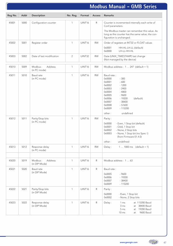
45001 5000 Configuration counter 1 UINT16 R Counter is incremented internally each write of Conf parameters.
The Modbus master can remember this value. As long as the counter has the same value, the con-figuration is unchanged.
45002 5001 Register order 1 UINT16 RW Order of registers at INT32 or FLOAT values
0x0001 HH-HL-LH-LL (default) 0x0000 LH-LL-HH-HL
45003 5002 Date of last modification 2 UINT32 RW Date (UNIX_TIMESTAMP) last change (Not managed by the device)
45010 5009 Modbus : Address (in PC mode)
1 UINT16 RW Modbus address : 1 … 247 (default = 1)
45011 5010 Baud rate (in PC mode)
1 UINT16 RW Baud rate : 0x0000 - 300 0x0001 - 600 0x0002 - 1200 0x0003 - 2400 0x0004 - 4800 0x0005 - 9600 0x0006 - 19200 (default) 0x0007 - 38400 0x0008 - 57600 0x0009 - 115200
other : undefined
45012 5011 Parity/Stop bits (in PC mode)
1 UINT16 RW Parity :
0x0000 - Even, 1 Stop bit (default) 0x0001 - Odd, 1 Stop bit 0x0002 - None, 2 Stop bits 0x0003 - None, 1 Stop bit (no Spec !) (from Firmware 01.4.0)
other : undefined
45013 5012 Response delay (in PC mode)
1 UINT16 RW Delay : 1 … 1000 ms (default = 1)
45020 5019 Modbus : Address (in DIP Mode)
1 UINT16 R Modbus address : 1 … 63
45021 5020 Baud rate (in DIP Mode)
1 UINT16 R Baud rate :
0x0005 - 9600 0x0006 - 19200 0x0007 - 38400 0x0009 - 115200
45022 5021 Parity/Stop bits (in DIP Mode)
1 UINT16 R Parity :
0x0000 - Even, 1 Stop bit 0x0002 - None, 2 Stop bits
45023 5022 Response delay (in DIP Mode)
1 UINT16 R Delay : 1 ms at 115200 Baud 3 ms at 38400 Baud 5 ms at 19200 Baud 10 ms at 9600 Baud

Modbus Manual - GMB Series
48 www.georgin.com
Reg No. Addr Description No. Reg. Format Access Remarks
48213 8212 Save settings 1 UINT16 W 0x0043
Speeds up the save procedure of settings.
Without this command the device saves changes approx. 5 seconds after the last write of a configu-ration parameter.

Modbus Manual - GMB Series
49www.georgin.com
References
[1] Modbus Organization : “MODBUS APPLICATION PROTOCOL SPECIFICATION V1.1b3”, 2012-04-12, http : //www.modbus.org/specs.php .
[2] Modbus Organization : “MODBUS over Serial Line - Specification and Implemen-tation Guide V1.02”, 2006-12-20, http://www.modbus.org/specs.php.
[3] RIA/EIA : “RIA-485 / EIA-485”, last revised 2003.
Revision history
Revision Date Changes / Notes
1 2016-03-04 Document created
2 2016-05-12 Register 40101, 40103 corrected
3 2016-11-28 GMB 96500 added
4 2016-12-13
Adding Parity NONE with 1 stop bit to Modbus configuration Reg. 45012
Description of In-Rail-Bus expanded
5 2017-01-19 GMB 96200, GMB 96700, GMB 96800 added

Configuration Manual - P series
www.georgin.com
www.georgin.com
Régulateurs GEORGIN
France14-16, rue Pierre Sémard - BP 107 - 92323 CHATILLON Cedex France
Tel. : +33 (0)1 46 12 60 00 - Fax : +33 (0)1 47 35 93 98 - Email : [email protected]
“Designed, developed and manufactured in France”
fc-m
od
bus
-en-
30/0
8/20
17Su
bje
ct t
o m
od
ifica
tions
due
to
tec
hnic
al a
dva
nces