modbus integration guidelines - coolautomation - … integration guidelines document revision 0.5...
TRANSCRIPT
© 2017 CoolAutomation LTD.
Modbus Integration Guidelines
Document Revision 0.5 10/17/2017
www.coolautomation.com
CoolMasterNetCooLinkNetCooLinkHub
Modbus IntegrationGuidelines
2ContentsModbus Integration Guidelines
www.coolautomation.com © 2017 CoolAutomation LTD.
Table of Contents
1 Connection 4
........................................................................................................................................................................ 41.1 Modbus RTU Connection
........................................................................................................................................................................ 51.2 Modbus IP Connection
2 Configuration 6
........................................................................................................................................................................ 62.1 Modbus RTU Configuration
.......................................................................................................................................................... 6Modbus Slave Address
.......................................................................................................................................................... 7Modbus RTU Frame Format
........................................................................................................................................................................ 72.2 Modbus IP Configuration
........................................................................................................................................................................ 72.3 VA's Configuration
3 Modbus Tables 10
........................................................................................................................................................................ 103.1 CoolMasterNet Modbus Tables
.......................................................................................................................................................... 12Special Devices
........................................................................................................................................................................ 123.2 CooLinkNet Modbus Tables
........................................................................................................................................................................ 133.3 HVAC Malfunction Codes
4 PRO Functionality 18
........................................................................................................................................................................ 184.1 PRO Modbus Tables
.......................................................................................................................................................... 18DK
......................................................................................................................................................... 18DK PRO Indoor Units
......................................................................................................................................................... 18DK PRO Outdoor Systems
......................................................................................................................................................... 20DK PRO Outdoor Units
.......................................................................................................................................................... 27ME
......................................................................................................................................................... 28ME PRO Indoor Units
......................................................................................................................................................... 28ME PRO Outdoor Units
5 Commands Reference 39
........................................................................................................................................................................ 395.1 line
........................................................................................................................................................................ 395.2 modbus
........................................................................................................................................................................ 405.3 va
6 Legacy CoolGate Mode 41
........................................................................................................................................................................ 416.1 DK
.......................................................................................................................................................... 41DK PRO via Airnet address
.......................................................................................................................................................... 42DK PRO Outdoor Systems
.......................................................................................................................................................... 42DK PRO Outdoor Units

3ContentsModbus Integration Guidelines
www.coolautomation.com © 2017 CoolAutomation LTD.

ConnectionModbus Integration Guidelines Rev 0.5 4
www.coolautomation.com © 2017 CoolAutomation LTD.
1 Connection
CoolAutomation devices support Modbus RTU and Modbus IP protocols with accordance to the ModbusOrganization specifications listed below:· MODBUS Application Protocol Specification· MODBUS over Serial Line Specification and Implementation Guide· MODBUS Messaging on TCP/IP Implementation GuideModbus RTU is supported by CoolMasterNet, CooLinkNet and CooLinkHub, Modbus IP is supported byCoolMasterNet and CooLinkHub.
1.1 Modbus RTU ConnectionIn Modbus RTU mode physical connection of the CoolAutomation devices is done over “Two-Wire” electricalinterface in accordance with EIA/TIA-485 standard. Connection is made via 485-A and 485-B terminals. Groundwire connection is not mandatory but highly recommended.
CoolMasterNet Modbus RTU Connection
In CoolMasterNet Line L3 is recommended for Modbus RTU connection, although Lines L4, L5, L6 and L7 can alsobe used for that purpose. Picture above shows connection to Line L3.
ConnectionModbus Integration Guidelines Rev 0.5 5
www.coolautomation.com © 2017 CoolAutomation LTD.
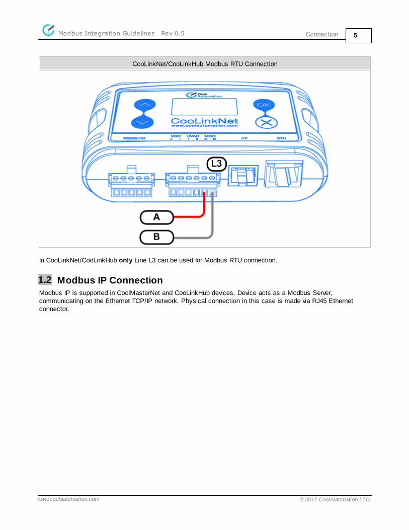
CooLinkNet/CooLinkHub Modbus RTU Connection
In CooLinkNet/CooLinkHub only Line L3 can be used for Modbus RTU connection.
1.2 Modbus IP ConnectionModbus IP is supported in CoolMasterNet and CooLinkHub devices. Device acts as a Modbus Server,communicating on the Ethernet TCP/IP network. Physical connection in this case is made via RJ45 Ethernetconnector.

ConfigurationModbus Integration Guidelines Rev 0.5 6
www.coolautomation.com © 2017 CoolAutomation LTD.
2 Configuration
CoolAutomation device must be properly configured to support Modbus functionality. Configuration is made viaCoolAutomation's proprietary ASCII_IF interface described in details in Programmer Reference Manual (PRM)document for the corresponding device. It is allowed to have a number of simultaneous Modbus RTU and Modbus IP connections to the same device.
2.1 Modbus RTU ConfigurationModbus RTU interface module of the CoolAutomation device has to be activated by assigning appropriatecommunication Line. In CoolMasterNet it is highly recommended to use Line L3, although it is possible to use anyof the L4, L5, L6, L7 lines. In CooLinkNet and CooLinkHub Line L3 usage for Modbus RTU is mandatory.
CoolMasterNet Modbus RTU activation: CooLinkNet/CooLinkHub Modbus RTU activation:
>line type L3 CG5
OK, Boot Required!
>line type L3 CLMB
OK, Boot Required!
To check if Modbus RTU module is already activated and read it 's parameters, including Slave Address, line
command should be used:CoolMasterNet: CooLinkNet/CooLinkHub:
>line
L1: DK Master U00/G00 myid:0B
Tx:2/2 Rx:2/2 TO:0/0 CS:0/0 Col:0/0 NAK:0/0
L2: Unused
Tx:0/0 Rx:0/0 TO:0/0 CS:0/0 Col:0/0 NAK:0/0
L3: CG5 Modbus Address:0x50(80) 9600_8N1
Tx:0/0 Rx:0/0 TO:0/0 CS:0/0 Col:0/0 NAK:0/0
L4: Unused
Tx:0/0 Rx:0/0 TO:0/0 CS:0/0 Col:0/0 NAK:0/0
L5: Unused
Tx:0/0 Rx:0/0 TO:0/0 CS:0/0 Col:0/0 NAK:0/0
L6: Unused
Tx:0/0 Rx:0/0 TO:0/0 CS:0/0 Col:0/0 NAK:0/0
L7: Unused
Tx:0/0 Rx:0/0 TO:0/0 CS:0/0 Col:0/0 NAK:0/0
L8: Unused
Tx:0/0 Rx:0/0 TO:0/0 CS:0/0 Col:0/0 NAK:0/0
OK
>line
L1: Unused
Tx:0/0 Rx:0/0 TO:0/0 CS:0/0 Col:0/0 NAK:0/0
L2: Unused
Tx:0/0 Rx:0/0 TO:0/0 CS:0/0 Col:0/0 NAK:0/0
L3: CLMB Address:0x50(80) 9600_8N1 Tx:0/0 Rx:0/0 TO:0/0 CS:0/0 Col:0/0 NAK:0/0
L4: M1M2 Slave U00/G00 Not Connected
Tx:0/0 Rx:0/0 TO:0/0 CS:0/0 Col:0/0 NAK:0/0
L5: Unused
Tx:0/0 Rx:0/0 TO:0/0 CS:0/0 Col:0/0 NAK:0/0
OK
Next: For CoolMasterNet and CooLinkHub VA's have to be configured to use Modbus RTU module. See: VA'sConfiguration.
2.1.1 Modbus Slave Address
Modbus Slave Address can be queried with line command or changed with line myid command. In the example
below the new Slave Address will become 0x51 (81 decimal) after power reset:
>line myid L3 51
OK, Boot Required!
The default (factory set) Modbus Slave Address for CoolAutomation devices is 0x50 hexadecimal (80 decimal).

ConfigurationModbus Integration Guidelines Rev 0.5 7
www.coolautomation.com © 2017 CoolAutomation LTD.
2.1.2 Modbus RTU Frame Format
The default Modbus RTU frame format in CoolAutomation devices is 9600_8N1:
Baud Rate 9600 bps Data Bits 8 Parity None Stop Bits 1
Frame format parameters are configurable with line baud command:
>line baud L3 19200_8N2
OK, Boot Required!
New frame format will be 19200 bps, 8 data bits, no parity, 2 stop bits.
2.2 Modbus IP ConfigurationModbus IP is supported in CoolMasterNet and CooLinkHub devices. CooLinkNet has no Modbus IP support. Modbus IP module is activated with below command:
>modbus IP enable
OK, Boot Required!
Modbus IP server is started by device only after it establishes an Ethernet link and gets proper IP address(dynamic via DHCP or static). Ethernet and IP management is done with ifconfig command that is out of the specof this document.
To query Modbus IP status use modbus command without parameters:
>modbus
ModBus IP : enabled
server port : 502
CG4/5 ignore : none
OK
The default TCP/IP port number used by Modbus IP Server is 502. This is "well-known" Ethernet port assigned forthe Modbus TCP/IP protocol. If required port number can be changed (new port number will be 503):
>modbus server port 503
OK, Boot Required!
Next: VA's have to be configured to use Modbus IP Server. See: VA's Configuration.
2.3 VA's ConfigurationVA's are used in CoolMasterNet and CooLinkHub devices. For CooLinkNet device this chapter is not applicable. VA's -Virtual Addresses are used in order to simplify translation of the Indoor Unit identifier/number - UID intoaddresses of related Modbus objects: holding registers, input registers, coils and discrete inputs.
UID is a string in format Ln.XYY. For Example:L1.102 - Indoor Unit 102 on line L1L2.003 - Indoor Unit 003 on line L2List of UID's detected (visible) by CoolAutomation device can be retrieved with ls command.

ConfigurationModbus Integration Guidelines Rev 0.5 8
www.coolautomation.com © 2017 CoolAutomation LTD.
>ls
L1.100 ON 19C 30C High Fan OK # 0
L1.101 OFF 28C 23C High Cool OK - 0
Each UID can have none, one or a number of associated VA's. VA's are plain numbers starting from 1. Device canautomatically allocate and associate VA's with existing (visible by ls command) UID's:
>va auto
OK
To query allocated VA's use va command without parameters:
>va
INDOORS
L1.100 --> 0001 [Hex: 0x0011 | Dec: 00017]
L1.101 --> 0002 [Hex: 0x0021 | Dec: 00033]
OK
VA reporting string has following fields:
UID AssociatedVA
Base Address Hex
Base Address Decimal
L1.100 0001 0x0011 00017
Base Address is a starting address of the Modbus objects block related to VA and it's UID. Any operations withIndoor Unit referenced by UID (query or change status) are made with Modbus objects from that block. Size of theModbus objects block for Indoor Unit is 16 adresses. Content of the Modbus objects block is described in CoolMasterNet Tables. Base Address is calculated as: Base Address = VA*16 +1
Below example shows relation between UID, VA, Base Address and Modbus objects
UID VA BaseAddress
Modbus Objects BlockDiscreteInputs
Coils Input Registers
HoldingRegisters
L1.100 0001 0x0011 ---> 0x0011 0x0011 0x0011 0x0011
... ... ... ...0x0020 0x0020 0x0020 0x0020
L1.101 0002 0x0021 ---> 0x0021 0x0021 0x0021 0x0021
... ... ... ...0x0030 0x0030 0x0030 0x0030
VA's can be allocated or deallocated (deleted) all together or separately. As shown above for automatic VA'sallocation va auto command is used. It is possible to allocate VA for specific UID. For example, allocate VA 0004
for UID L1.102:
>va + L1.102 0004
OK
In this case UID does not have to be detected (visible) by CoolAutomation device at the VA allocation time. It isallowed to allocate a number of VA's for any given UID.
To delete all allocated VA's:
ConfigurationModbus Integration Guidelines Rev 0.5 9
www.coolautomation.com © 2017 CoolAutomation LTD.
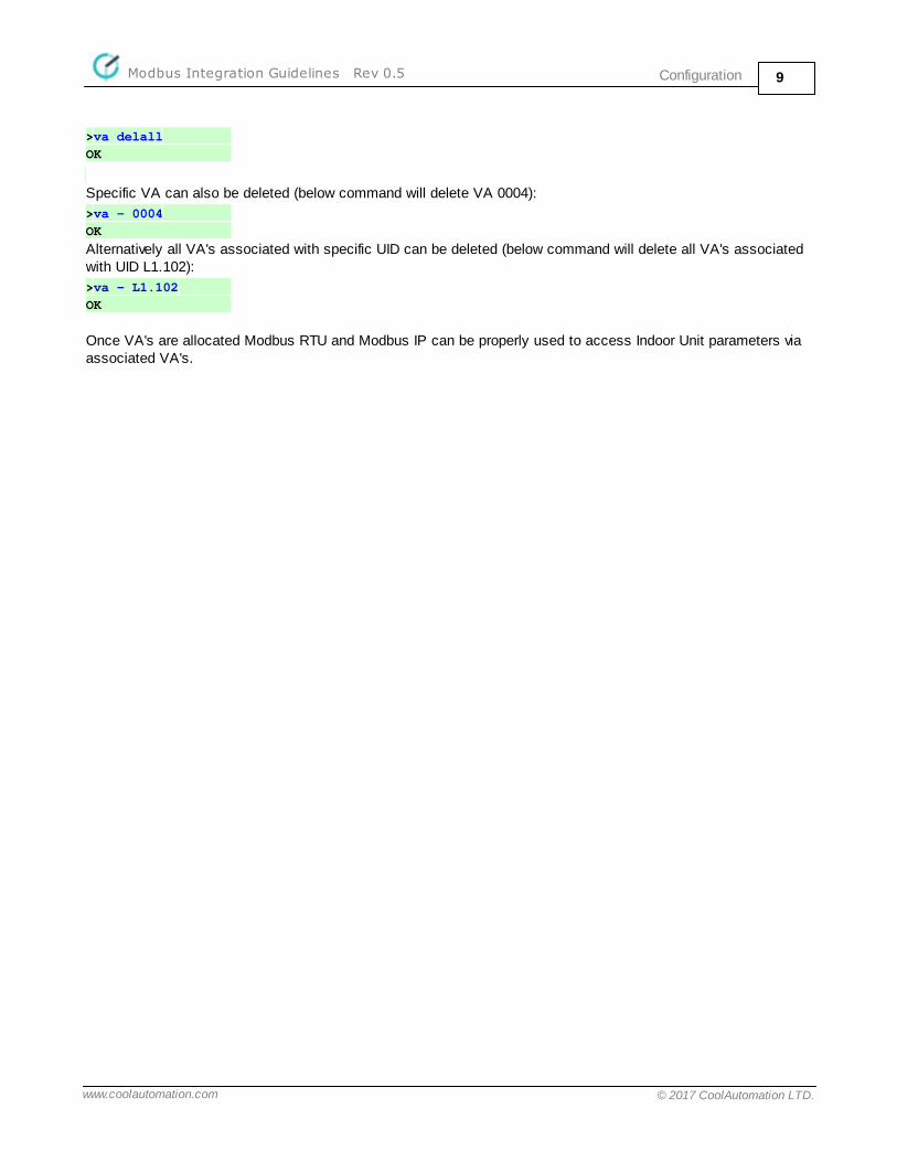
>va delall
OK
Specific VA can also be deleted (below command will delete VA 0004):
>va - 0004
OK
Alternatively all VA's associated with specific UID can be deleted (below command will delete all VA's associatedwith UID L1.102):
>va - L1.102
OK
Once VA's are allocated Modbus RTU and Modbus IP can be properly used to access Indoor Unit parameters viaassociated VA's.
Modbus TablesModbus Integration Guidelines Rev 0.5 10
www.coolautomation.com © 2017 CoolAutomation LTD.
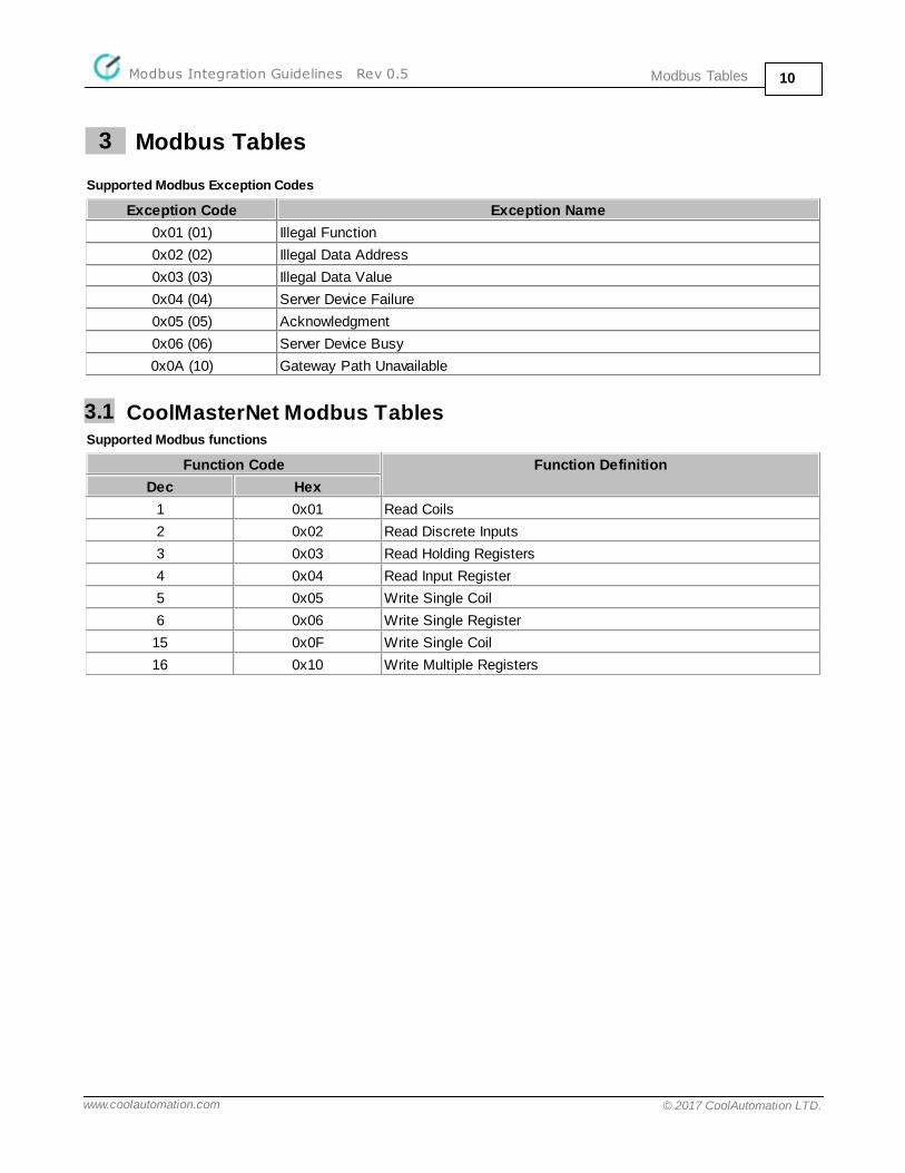
3 Modbus Tables
Supported Modbus Exception Codes
Exception Code Exception Name
0x01 (01) Illegal Function
0x02 (02) Illegal Data Address
0x03 (03) Illegal Data Value
0x04 (04) Server Device Failure
0x05 (05) Acknowledgment
0x06 (06) Server Device Busy
0x0A (10) Gateway Path Unavailable
3.1 CoolMasterNet Modbus TablesSupported Modbus functions
Function Code Function Definition
Dec Hex
1 0x01 Read Coils
2 0x02 Read Discrete Inputs
3 0x03 Read Holding Registers
4 0x04 Read Input Register
5 0x05 Write Single Coil
6 0x06 Write Single Register
15 0x0F Write Single Coil
16 0x10 Write Multiple Registers

Modbus TablesModbus Integration Guidelines Rev 0.5 11
www.coolautomation.com © 2017 CoolAutomation LTD.
Indoor Unit Modbus objects block
Base Address
Holding Registers Input Registers Coils Discrete Inputs
+0 Operation Mode
0-Cool 4-HAUX 8-VAM Auto
1-Heat 5-Fan 9-VAM Bypass
2-Auto 6-HH 10-VAM Heat Exc
3-Dry 11-VAM Normal
UID Ln.XYY
Bits
15..12
Bits
11..8
Bits
7..0
Ln X YY
On/Off
0-OFF
1-ON
Reserved
+1 Fan Speed
0-Low 3-Auto
1-Med 4-Top 7-VAM Super Hi
2-High 5-Very Lo 8-VAM Lo FreshUp
9-VAM Hi FreshUp
Room Temperaturex10 °C
Filter Sign
+2 Set Temperature x10 °C HVAC Malfunction
Code String2
First two characters
External TerminalsStatus
(Read Only)0-Open, 1-Closed (short)
+3 On/Off
0-OFF
1-ON
HVAC Malfunction
Code String2
Last two charactersInhibit4
+4 Filter Sign
Reserved
Reserved
+5 Swing
0-Vertical 1-30 deg 5-Auto
4-Horizontal 2-45 deg 6-OFF
3-60 deg
+6 Room Temperature x10 °C(Read Only)
+7 HVAC Malfunction Code(Read Only)
+8 Local Wall Controller
Lock Bits3
LSB
Bit 0 - Inhibit On/Off control
Bit 1 - Inhibit Mode control
Bit 2 - Inhibit Set Temperature control
Bit 7 - Inhibit All control operations
+9 Set Temperature Limits1
v0.4.4
Digital Output 1 Digital Input 1
+10 0xA
Reserved
Digital Output 2 Digital Input 2+11 0xB Digital Output 3 Digital Input 3+12 0xC Digital Output 4 Digital Input 4+13 0xD Analog Input 1 Digital Output 5 Digital Input 5+14 0xE Analog Input 2 Digital Output 6 Digital Input 6+15 0xF Reserved Reserved Reserved
1 Set Temperature Limits Encoding
Modbus TablesModbus Integration Guidelines Rev 0.5 12
www.coolautomation.com © 2017 CoolAutomation LTD.
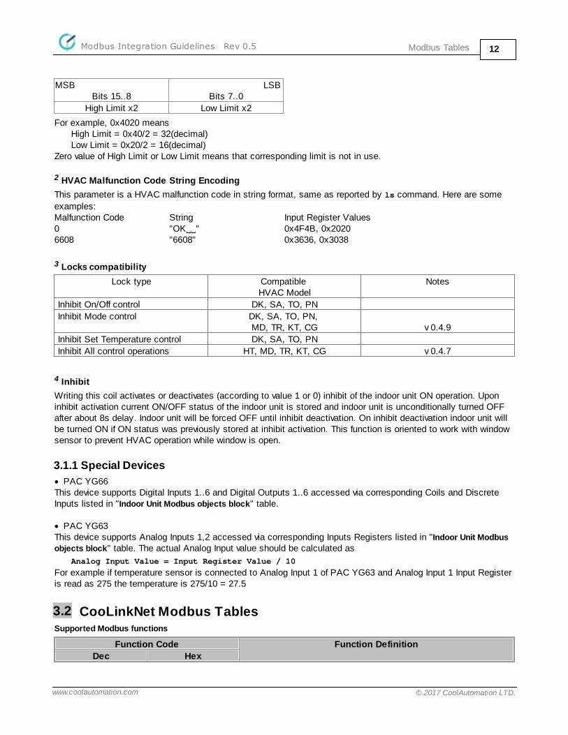
MSBBits 15..8
LSB Bits 7..0
High Limit x2 Low Limit x2
For example, 0x4020 means High Limit = 0x40/2 = 32(decimal)Low Limit = 0x20/2 = 16(decimal)
Zero value of High Limit or Low Limit means that corresponding limit is not in use.
2 HVAC Malfunction Code String Encoding
This parameter is a HVAC malfunction code in string format, same as reported by ls command. Here are some
examples:Malfunction Code String Input Register Values0 "OKVV" 0x4F4B, 0x20206608 "6608" 0x3636, 0x3038
3 Locks compatibility
Lock type Compatible HVAC Model
Notes
Inhibit On/Off control DK, SA, TO, PN
Inhibit Mode control DK, SA, TO, PN, MD, TR, KT, CG v 0.4.9
Inhibit Set Temperature control DK, SA, TO, PN
Inhibit All control operations HT, MD, TR, KT, CG v 0.4.7
4 Inhibit
Writing this coil activates or deactivates (according to value 1 or 0) inhibit of the indoor unit ON operation. Uponinhibit activation current ON/OFF status of the indoor unit is stored and indoor unit is unconditionally turned OFFafter about 8s delay. Indoor unit will be forced OFF until inhibit deactivation. On inhibit deactivation indoor unit willbe turned ON if ON status was previously stored at inhibit activation. This function is oriented to work with windowsensor to prevent HVAC operation while window is open.
3.1.1 Special Devices
· PAC YG66This device supports Digital Inputs 1..6 and Digital Outputs 1..6 accessed via corresponding Coils and DiscreteInputs listed in "Indoor Unit Modbus objects block" table.
· PAC YG63This device supports Analog Inputs 1,2 accessed via corresponding Inputs Registers listed in "Indoor Unit Modbus
objects block" table. The actual Analog Input value should be calculated as
Analog Input Value = Input Register Value / 10
For example if temperature sensor is connected to Analog Input 1 of PAC YG63 and Analog Input 1 Input Registeris read as 275 the temperature is 275/10 = 27.5
3.2 CooLinkNet Modbus TablesSupported Modbus functions
Function Code Function Definition
Dec Hex

Modbus TablesModbus Integration Guidelines Rev 0.5 13
www.coolautomation.com © 2017 CoolAutomation LTD.
3 0x03 Read Holding Registers
6 0x06 Write Single Register
16 0x10 Write Multiple Registers
Holding Reg
Address* DescriptionRead
Write
Required**Notes
Hex Dec Version Model
CooLinkNet Internals
0001 1 CooLinkNet Version R Major*100 + Minor*10 + SubMinor
0002 2 CooLinkNet S/N R Low er 16 bit
0003 3 CooLinkNet Model R Tw o ASCII characters
0004 4 Modbus Address R W Modbus Address change is
effective only after reset
0005 5 Reset W 1 - Enter Boot mode
CooLinkNet does not respond to
the w rite request to this register
2 - Reset
0010 16 Internal State · 0 - Not Connected to RC line· 1 - Connecting· 2 - Connected as single RC· 3 - Connected as Master RC. Detected
Slave RC· 4 - Connected as Slave RC
R
0011 17 0 - Master Mode (default) 1 - Slave Mode R W 0.0.4
0021 33 UID R MSB - X, LSB - YY
Indoor Status and Control
0100 256 On/Off 0-Off, 1-On R W
0101 257 Operation Mode0-Cool 3-Dry
1-Heat 4-HAUX
2-Auto 5-Fan
R W
0102 258 Fan Speed0-Low 3-Auto
1-Med 4-Top
2-High
R W
0103 259 Set Point °C R W
0104 260 Failure Code R
0105 261 Indoor Ambient Temperature °C R MSB - Integer Part
LSB - Fraction Part * 0.01
0110 272 Feed Temperature °C R W 0.2.4 0xFFFF - disable feed
* If Version or Model is not specified, it means that register is supported in any CooLinkNet version and/or model.
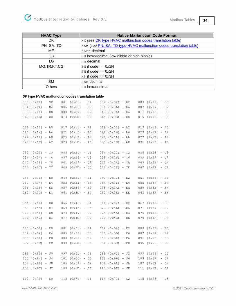
3.3 HVAC Malfunction CodesThe value read from "HVAC Malfunction Code" holding register can be translated into native malfunction codeapplicable for specific HVAC manufacturer. In most cases that value and native code are equal but for some HVACmodels translation to alphanumeric representation required. Following tables can be used for such translation. Zero value (0x00) means that there are no HVAC malfunctions.
Modbus TablesModbus Integration Guidelines Rev 0.5 14
www.coolautomation.com © 2017 CoolAutomation LTD.
HVAC Type Native Malfunction Code Format
DK XX (see DK type HVAC malfunction codes translation table)
PN, SA, TO Xnn (see PN, SA, TO type HVAC malfunction codes translation table)
ME nnnn decimal
GR HH hexadecimal (low nibble or high nibble)
LG nn decimal
MG,TR,KT,CG EH if code == 0x1H
PH if code == 0x2H
H# if code == 0x3H
SM nnn decimal
Others HH hexadecimal
DK type HVAC malfunction codes translation table
000 (0x00) - OK 001 (0x01) - 01 002 (0x02) - 02 003 (0x03) - 03
004 (0x04) - 04 005 (0x05) - 05 006 (0x06) - 06 007 (0x07) - 07
008 (0x08) - 08 009 (0x09) - 09 010 (0x0A) - 0A 011 (0x0B) - 0H
012 (0x0C) - 0C 013 (0x0D) - 0J 014 (0x0E) - 0E 015 (0x0F) - 0F
016 (0x10) - A0 017 (0x11) - A1 018 (0x12) - A2 019 (0x13) - A3
020 (0x14) - A4 021 (0x15) - A5 022 (0x16) - A6 023 (0x17) - A7
024 (0x18) - A8 025 (0x19) - A9 026 (0x1A) - AA 027 (0x1B) - AH
028 (0x1C) - AC 029 (0x1D) - AJ 030 (0x1E) - AE 031 (0x1F) - AF
032 (0x20) - C0 033 (0x21) - C1 034 (0x22) - C2 035 (0x23) - C3
036 (0x24) - C4 037 (0x25) - C5 038 (0x26) - C6 039 (0x27) - C7
040 (0x28) - C8 041 (0x29) - C9 042 (0x2A) - CA 043 (0x2B) - CH
044 (0x2C) - CC 045 (0x2D) - CJ 046 (0x2E) - CE 047 (0x2F) - CF
048 (0x30) - E0 049 (0x31) - E1 050 (0x32) - E2 051 (0x33) - E3
052 (0x34) - E4 053 (0x35) - E5 054 (0x36) - E6 055 (0x37) - E7
056 (0x38) - E8 057 (0x39) - E9 058 (0x3A) - EA 059 (0x3B) - EH
060 (0x3C) - EC 061 (0x3D) - EJ 062 (0x3E) - EE 063 (0x3F) - EF
064 (0x40) - H0 065 (0x41) - H1 066 (0x42) - H2 067 (0x43) - H3
068 (0x44) - H4 069 (0x45) - H5 070 (0x46) - H6 071 (0x47) - H7
072 (0x48) - H8 073 (0x49) - H9 074 (0x4A) - HA 075 (0x4B) - HH
076 (0x4C) - HC 077 (0x4D) - HJ 078 (0x4E) - HE 079 (0x4F) - HF
080 (0x50) - F0 081 (0x51) - F1 082 (0x52) - F2 083 (0x53) - F3
084 (0x54) - F4 085 (0x55) - F5 086 (0x56) - F6 087 (0x57) - F7
088 (0x58) - F8 089 (0x59) - F9 090 (0x5A) - FA 091 (0x5B) - FH
092 (0x5C) - FC 093 (0x5D) - FJ 094 (0x5E) - FE 095 (0x5F) - FF
096 (0x60) - J0 097 (0x61) - J1 098 (0x62) - J2 099 (0x63) - J3
100 (0x64) - J4 101 (0x65) - J5 102 (0x66) - J6 103 (0x67) - J7
104 (0x68) - J8 105 (0x69) - J9 106 (0x6A) - JA 107 (0x6B) - JH
108 (0x6C) - JC 109 (0x6D) - JJ 110 (0x6E) - JE 111 (0x6F) - JF
112 (0x70) - L0 113 (0x71) - L1 114 (0x72) - L2 115 (0x73) - L3
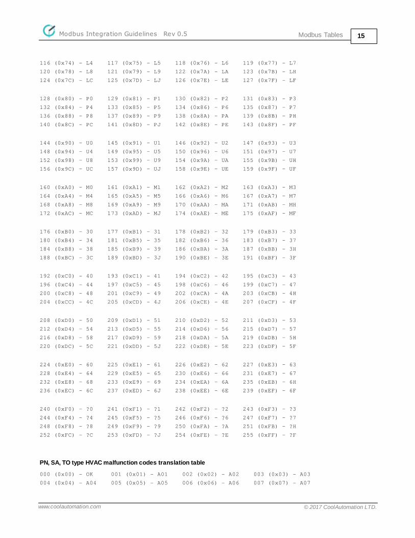
Modbus TablesModbus Integration Guidelines Rev 0.5 15
www.coolautomation.com © 2017 CoolAutomation LTD.
116 (0x74) - L4 117 (0x75) - L5 118 (0x76) - L6 119 (0x77) - L7
120 (0x78) - L8 121 (0x79) - L9 122 (0x7A) - LA 123 (0x7B) - LH
124 (0x7C) - LC 125 (0x7D) - LJ 126 (0x7E) - LE 127 (0x7F) - LF
128 (0x80) - P0 129 (0x81) - P1 130 (0x82) - P2 131 (0x83) - P3
132 (0x84) - P4 133 (0x85) - P5 134 (0x86) - P6 135 (0x87) - P7
136 (0x88) - P8 137 (0x89) - P9 138 (0x8A) - PA 139 (0x8B) - PH
140 (0x8C) - PC 141 (0x8D) - PJ 142 (0x8E) - PE 143 (0x8F) - PF
144 (0x90) - U0 145 (0x91) - U1 146 (0x92) - U2 147 (0x93) - U3
148 (0x94) - U4 149 (0x95) - U5 150 (0x96) - U6 151 (0x97) - U7
152 (0x98) - U8 153 (0x99) - U9 154 (0x9A) - UA 155 (0x9B) - UH
156 (0x9C) - UC 157 (0x9D) - UJ 158 (0x9E) - UE 159 (0x9F) - UF
160 (0xA0) - M0 161 (0xA1) - M1 162 (0xA2) - M2 163 (0xA3) - M3
164 (0xA4) - M4 165 (0xA5) - M5 166 (0xA6) - M6 167 (0xA7) - M7
168 (0xA8) - M8 169 (0xA9) - M9 170 (0xAA) - MA 171 (0xAB) - MH
172 (0xAC) - MC 173 (0xAD) - MJ 174 (0xAE) - ME 175 (0xAF) - MF
176 (0xB0) - 30 177 (0xB1) - 31 178 (0xB2) - 32 179 (0xB3) - 33
180 (0xB4) - 34 181 (0xB5) - 35 182 (0xB6) - 36 183 (0xB7) - 37
184 (0xB8) - 38 185 (0xB9) - 39 186 (0xBA) - 3A 187 (0xBB) - 3H
188 (0xBC) - 3C 189 (0xBD) - 3J 190 (0xBE) - 3E 191 (0xBF) - 3F
192 (0xC0) - 40 193 (0xC1) - 41 194 (0xC2) - 42 195 (0xC3) - 43
196 (0xC4) - 44 197 (0xC5) - 45 198 (0xC6) - 46 199 (0xC7) - 47
200 (0xC8) - 48 201 (0xC9) - 49 202 (0xCA) - 4A 203 (0xCB) - 4H
204 (0xCC) - 4C 205 (0xCD) - 4J 206 (0xCE) - 4E 207 (0xCF) - 4F
208 (0xD0) - 50 209 (0xD1) - 51 210 (0xD2) - 52 211 (0xD3) - 53
212 (0xD4) - 54 213 (0xD5) - 55 214 (0xD6) - 56 215 (0xD7) - 57
216 (0xD8) - 58 217 (0xD9) - 59 218 (0xDA) - 5A 219 (0xDB) - 5H
220 (0xDC) - 5C 221 (0xDD) - 5J 222 (0xDE) - 5E 223 (0xDF) - 5F
224 (0xE0) - 60 225 (0xE1) - 61 226 (0xE2) - 62 227 (0xE3) - 63
228 (0xE4) - 64 229 (0xE5) - 65 230 (0xE6) - 66 231 (0xE7) - 67
232 (0xE8) - 68 233 (0xE9) - 69 234 (0xEA) - 6A 235 (0xEB) - 6H
236 (0xEC) - 6C 237 (0xED) - 6J 238 (0xEE) - 6E 239 (0xEF) - 6F
240 (0xF0) - ?0 241 (0xF1) - ?1 242 (0xF2) - ?2 243 (0xF3) - ?3
244 (0xF4) - ?4 245 (0xF5) - ?5 246 (0xF6) - ?6 247 (0xF7) - ?7
248 (0xF8) - ?8 249 (0xF9) - ?9 250 (0xFA) - ?A 251 (0xFB) - ?H
252 (0xFC) - ?C 253 (0xFD) - ?J 254 (0xFE) - ?E 255 (0xFF) - ?F
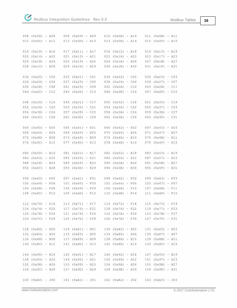
PN, SA, TO type HVAC malfunction codes translation table
000 (0x00) - OK 001 (0x01) - A01 002 (0x02) - A02 003 (0x03) - A03
004 (0x04) - A04 005 (0x05) - A05 006 (0x06) - A06 007 (0x07) - A07
Modbus TablesModbus Integration Guidelines Rev 0.5 16
www.coolautomation.com © 2017 CoolAutomation LTD.
008 (0x08) - A08 009 (0x09) - A09 010 (0x0A) - A10 011 (0x0B) - A11
012 (0x0C) - A12 013 (0x0D) - A13 014 (0x0E) - A14 015 (0x0F) - A15
016 (0x10) - A16 017 (0x11) - A17 018 (0x12) - A18 019 (0x13) - A19
020 (0x14) - A20 021 (0x15) - A21 022 (0x16) - A22 023 (0x17) - A23
024 (0x18) - A24 025 (0x19) - A25 026 (0x1A) - A26 027 (0x1B) - A27
028 (0x1C) - A28 029 (0x1D) - A29 030 (0x1E) - A30 031 (0x1F) - A31
032 (0x20) - C00 033 (0x21) - C01 034 (0x22) - C02 035 (0x23) - C03
036 (0x24) - C04 037 (0x25) - C05 038 (0x26) - C06 039 (0x27) - C07
040 (0x28) - C08 041 (0x29) - C09 042 (0x2A) - C10 043 (0x2B) - C11
044 (0x2C) - C12 045 (0x2D) - C13 046 (0x2E) - C14 047 (0x2F) - C15
048 (0x30) - C16 049 (0x31) - C17 050 (0x32) - C18 051 (0x33) - C19
052 (0x34) - C20 053 (0x35) - C21 054 (0x36) - C22 055 (0x37) - C23
056 (0x38) - C24 057 (0x39) - C25 058 (0x3A) - C26 059 (0x3B) - C27
060 (0x3C) - C28 061 (0x3D) - C29 062 (0x3E) - C30 063 (0x3F) - C31
064 (0x40) - E00 065 (0x41) - E01 066 (0x42) - E02 067 (0x43) - E03
068 (0x44) - E04 069 (0x45) - E05 070 (0x46) - E06 071 (0x47) - E07
072 (0x48) - E08 073 (0x49) - E09 074 (0x4A) - E10 075 (0x4B) - E11
076 (0x4C) - E12 077 (0x4D) - E13 078 (0x4E) - E14 079 (0x4F) - E15
080 (0x50) - E16 081 (0x51) - E17 082 (0x52) - E18 083 (0x53) - E19
084 (0x54) - E20 085 (0x55) - E21 086 (0x56) - E22 087 (0x57) - E23
088 (0x58) - E24 089 (0x59) - E25 090 (0x5A) - E26 091 (0x5B) - E27
092 (0x5C) - E28 093 (0x5D) - E29 094 (0x5E) - E30 095 (0x5F) - E31
096 (0x60) - F00 097 (0x61) - F01 098 (0x62) - F02 099 (0x63) - F03
100 (0x64) - F04 101 (0x65) - F05 102 (0x66) - F06 103 (0x67) - F07
104 (0x68) - F08 105 (0x69) - F09 106 (0x6A) - F10 107 (0x6B) - F11
108 (0x6C) - F12 109 (0x6D) - F13 110 (0x6E) - F14 111 (0x6F) - F15
112 (0x70) - F16 113 (0x71) - F17 114 (0x72) - F18 115 (0x73) - F19
116 (0x74) - F20 117 (0x75) - F21 118 (0x76) - F22 119 (0x77) - F23
120 (0x78) - F24 121 (0x79) - F25 122 (0x7A) - F26 123 (0x7B) - F27
124 (0x7C) - F28 125 (0x7D) - F29 126 (0x7E) - F30 127 (0x7F) - F31
128 (0x80) - H00 129 (0x81) - H01 130 (0x82) - H02 131 (0x83) - H03
132 (0x84) - H04 133 (0x85) - H05 134 (0x86) - H06 135 (0x87) - H07
136 (0x88) - H08 137 (0x89) - H09 138 (0x8A) - H10 139 (0x8B) - H11
140 (0x8C) - H12 141 (0x8D) - H13 142 (0x8E) - H14 143 (0x8F) - H15
144 (0x90) - H16 145 (0x91) - H17 146 (0x92) - H18 147 (0x93) - H19
148 (0x94) - H20 149 (0x95) - H21 150 (0x96) - H22 151 (0x97) - H23
152 (0x98) - H24 153 (0x99) - H25 154 (0x9A) - H26 155 (0x9B) - H27
156 (0x9C) - H28 157 (0x9D) - H29 158 (0x9E) - H30 159 (0x9F) - H31
160 (0xA0) - J00 161 (0xA1) - J01 162 (0xA2) - J02 163 (0xA3) - J03

Modbus TablesModbus Integration Guidelines Rev 0.5 17
www.coolautomation.com © 2017 CoolAutomation LTD.
164 (0xA4) - J04 165 (0xA5) - J05 166 (0xA6) - J06 167 (0xA7) - J07
168 (0xA8) - J08 169 (0xA9) - J09 170 (0xAA) - J10 171 (0xAB) - J11
172 (0xAC) - J12 173 (0xAD) - J13 174 (0xAE) - J14 175 (0xAF) - J15
176 (0xB0) - J16 177 (0xB1) - J17 178 (0xB2) - J18 179 (0xB3) - J19
180 (0xB4) - J20 181 (0xB5) - J21 182 (0xB6) - J22 183 (0xB7) - J23
184 (0xB8) - J24 185 (0xB9) - J25 186 (0xBA) - J26 187 (0xBB) - J27
188 (0xBC) - J28 189 (0xBD) - J29 190 (0xBE) - J30 191 (0xBF) - J31
192 (0xC0) - L00 193 (0xC1) - L01 194 (0xC2) - L02 195 (0xC3) - L03
196 (0xC4) - L04 197 (0xC5) - L05 198 (0xC6) - L06 199 (0xC7) - L07
200 (0xC8) - L08 201 (0xC9) - L09 202 (0xCA) - L10 203 (0xCB) - L11
204 (0xCC) - L12 205 (0xCD) - L13 206 (0xCE) - L14 207 (0xCF) - L15
208 (0xD0) - L16 209 (0xD1) - L17 210 (0xD2) - L18 211 (0xD3) - L19
212 (0xD4) - L20 213 (0xD5) - L21 214 (0xD6) - L22 215 (0xD7) - L23
216 (0xD8) - L24 217 (0xD9) - L25 218 (0xDA) - L26 219 (0xDB) - L27
220 (0xDC) - L28 221 (0xDD) - L29 222 (0xDE) - L30 223 (0xDF) - L31
224 (0xE0) - P00 225 (0xE1) - P01 226 (0xE2) - P02 227 (0xE3) - P03
228 (0xE4) - P04 229 (0xE5) - P05 230 (0xE6) - P06 231 (0xE7) - P07
232 (0xE8) - P08 233 (0xE9) - P09 234 (0xEA) - P10 235 (0xEB) - P11
236 (0xEC) - P12 237 (0xED) - P13 238 (0xEE) - P14 239 (0xEF) - P15
240 (0xF0) - P16 241 (0xF1) - P17 242 (0xF2) - P18 243 (0xF3) - P19
244 (0xF4) - P20 245 (0xF5) - P21 246 (0xF6) - P22 247 (0xF7) - P23
248 (0xF8) - P24 249 (0xF9) - P25 250 (0xFA) - P26 251 (0xFB) - P27
252 (0xFC) - P28 253 (0xFD) - P29 254 (0xFE) - P30 255 (0xFF) - P31
PRO FunctionalityModbus Integration Guidelines Rev 0.5 18
www.coolautomation.com © 2017 CoolAutomation LTD.
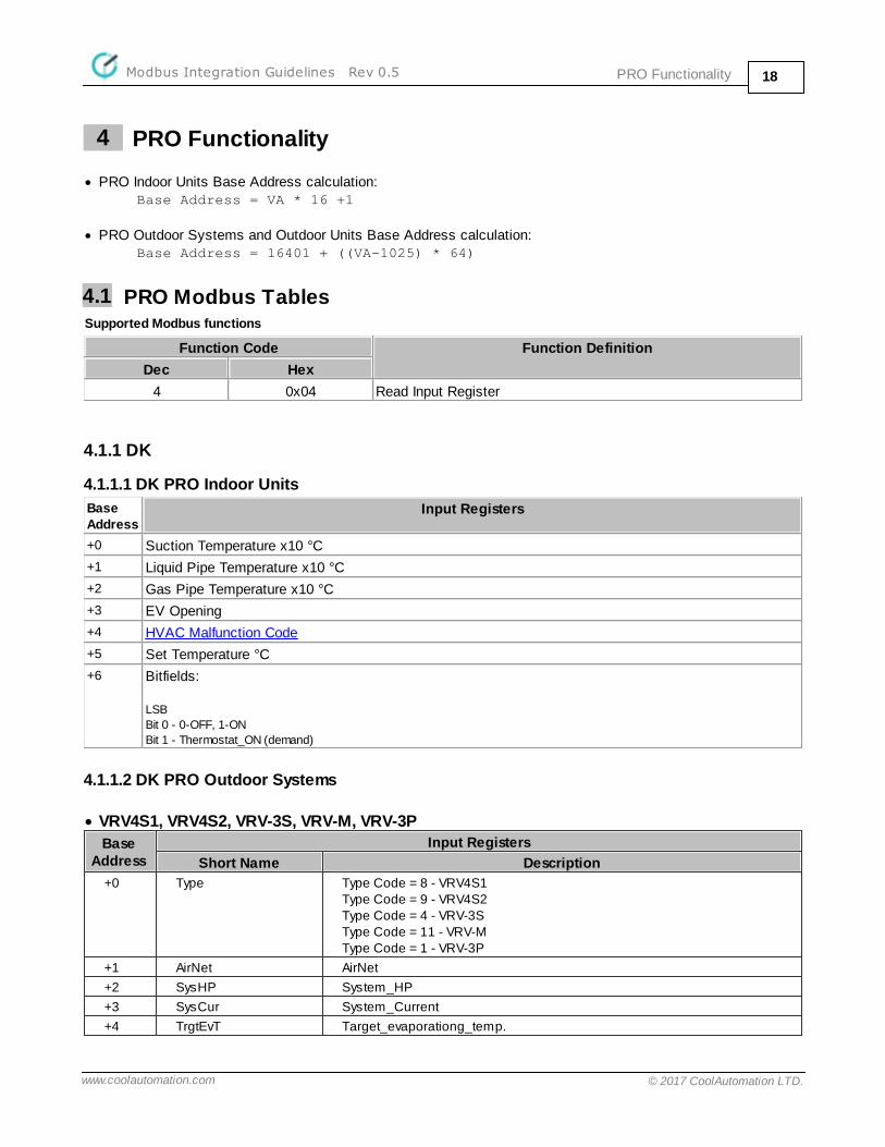
4 PRO Functionality
· PRO Indoor Units Base Address calculation:Base Address = VA * 16 +1
· PRO Outdoor Systems and Outdoor Units Base Address calculation:Base Address = 16401 + ((VA-1025) * 64)
4.1 PRO Modbus TablesSupported Modbus functions
Function Code Function Definition
Dec Hex
4 0x04 Read Input Register
4.1.1 DK
4.1.1.1 DK PRO Indoor Units
Base Address
Input Registers
+0 Suction Temperature x10 °C
+1 Liquid Pipe Temperature x10 °C
+2 Gas Pipe Temperature x10 °C
+3 EV Opening
+4 HVAC Malfunction Code
+5 Set Temperature °C
+6 Bitfields:
LSB
Bit 0 - 0-OFF, 1-ON
Bit 1 - Thermostat_ON (demand)
4.1.1.2 DK PRO Outdoor Systems
· VRV4S1, VRV4S2, VRV-3S, VRV-M, VRV-3P
Base Address
Input Registers
Short Name Description
+0 Type Type Code = 8 - VRV4S1Type Code = 9 - VRV4S2Type Code = 4 - VRV-3SType Code = 11 - VRV-MType Code = 1 - VRV-3P
+1 AirNet AirNet
+2 SysHP System_HP
+3 SysCur System_Current
+4 TrgtEvT Target_evaporationg_temp.

PRO FunctionalityModbus Integration Guidelines Rev 0.5 19
www.coolautomation.com © 2017 CoolAutomation LTD.
Base Address
Input Registers
Short Name Description
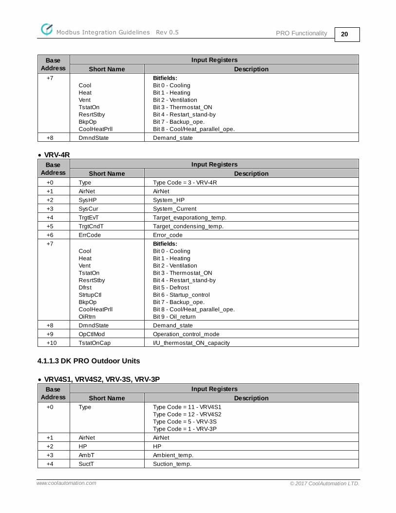
+5 TrgtCndT Target_condensing_temp.
+6 ErrCode Error_code
+7CoolHeatVentTstatOnResrtStbyBkpOp
Bitfields:Bit 0 - CoolingBit 1 - HeatingBit 2 - VentilationBit 3 - Thermostat_ONBit 4 - Restart_stand-byBit 7 - Backup_ope.
+8 DmndState Demand_state
· VRV4S3, VRVX, VRV4-EU
Base Address
Input Registers
Short Name Description
+0 Type Type Code = 10 - VRV4S3Type Code = 6 - VRVXType Code = 7 - VRV4-EU
+1 AirNet AirNet
+2 SysHP System_HP
+3 SysCur System_Current
+4 TrgtEvT Target_evaporationg_temp.
+5 TrgtCndT Target_condensing_temp.
+6 ErrCode Error_code
+7CoolHeatVentTstatOnResrtStbyDfrstStrtupCtlBkpOpOiRtrn
Bitfields:Bit 0 - CoolingBit 1 - HeatingBit 2 - VentilationBit 3 - Thermostat_ONBit 4 - Restart_stand-byBit 5 - DefrostBit 6 - Startup_controlBit 7 - Backup_ope.Bit 9 - Oil_return
+8 DmndState Demand_state
+9 OpCtlMod Operation_control_mode
+10 TstatOnCap I/U_thermostat_ON_capacity
· VRV-3R, VRV3C
Base Address
Input Registers
Short Name Description
+0 Type Type Code = 5 - VRV-3RType Code = 2 - VRV3C
+1 AirNet AirNet
+2 SysHP System_HP
+3 SysCur System_Current
+4 TrgtEvT Target_evaporationg_temp.
+5 TrgtCndT Target_condensing_temp.
+6 ErrCode Error_code
PRO FunctionalityModbus Integration Guidelines Rev 0.5 20
www.coolautomation.com © 2017 CoolAutomation LTD.
Base Address
Input Registers
Short Name Description
+7CoolHeatVentTstatOnResrtStbyBkpOpCoolHeatPrll
Bitfields:Bit 0 - CoolingBit 1 - HeatingBit 2 - VentilationBit 3 - Thermostat_ONBit 4 - Restart_stand-byBit 7 - Backup_ope.Bit 8 - Cool/Heat_parallel_ope.
+8 DmndState Demand_state
· VRV-4R
Base Address
Input Registers
Short Name Description
+0 Type Type Code = 3 - VRV-4R
+1 AirNet AirNet
+2 SysHP System_HP
+3 SysCur System_Current
+4 TrgtEvT Target_evaporationg_temp.
+5 TrgtCndT Target_condensing_temp.
+6 ErrCode Error_code
+7CoolHeatVentTstatOnResrtStbyDfrstStrtupCtlBkpOpCoolHeatPrllOiRtrn
Bitfields:Bit 0 - CoolingBit 1 - HeatingBit 2 - VentilationBit 3 - Thermostat_ONBit 4 - Restart_stand-byBit 5 - DefrostBit 6 - Startup_controlBit 7 - Backup_ope.Bit 8 - Cool/Heat_parallel_ope.Bit 9 - Oil_return
+8 DmndState Demand_state
+9 OpCtlMod Operation_control_mode
+10 TstatOnCap I/U_thermostat_ON_capacity
4.1.1.3 DK PRO Outdoor Units
· VRV4S1, VRV4S2, VRV-3S, VRV-3P
Base Address
Input Registers
Short Name Description
+0 Type Type Code = 11 - VRV4S1Type Code = 12 - VRV4S2Type Code = 5 - VRV-3SType Code = 1 - VRV-3P
+1 AirNet AirNet
+2 HP HP
+3 AmbT Ambient_temp.
+4 SuctT Suction_temp.

PRO FunctionalityModbus Integration Guidelines Rev 0.5 21
www.coolautomation.com © 2017 CoolAutomation LTD.
Base Address
Input Registers
Short Name Description
+5 EvT Evaporating_temp.
+6 CndT Condensing_temp.
+7 InvRS Inverter_Revolution_speed
+8 EVOp1 EV_opening_1
+9 EVOp2 EV_opening_2
+12 CTSTD1 CT1(STD1)
+13 CTSTD2 CT2(STD2)
+14 FanStp Fan_step
+15 CilT R4T_:Coil_temp.
+16 ScCilExtT Subcooling_Coil_exit_Temp.
+17 DschTInv Disch._temp.(INV)
+18 DschTStd1 Disch._temp.(STD1)
+19 DschTStd2 Disch._temp.(STD2)
+20 AccEntrT Accumulator_Entrance_Temp.
+21 RcvrLiqT Receiver_Liquid_Temp.
+22 InvT Inverter_temp.
+23 InvCur Inverter_current
+24 InvFanCur INV_FAN_current
+25Comp1InvComp2Std1Comp3Std2OiRtrnHotGasCcH1CcH2CcH3SoftStrtResrtStbyMulOiErrStateEnrgyCutOutpHiPRtryLoPRtryDischPipRtry
Bitfields:Bit 0 - Compressor1(INV)Bit 1 - Compressor2(STD1)Bit 2 - Compressor3(STD2)Bit 3 - Oil_returnBit 4 - Hot_GasBit 5 - CH1:Crankcase_HeaterBit 6 - CH2:Crankcase_HeaterBit 7 - CH3:Crankcase_HeaterBit 8 - Soft_startBit 9 - Restart_stand-byBit 10 - multi_oilBit 11 - Unit_Error_statBit 12 - Energy_cut_outputBit 13 - High_pressure_retryBit 14 - Low_pressure_retryBit 15 - Disch._pipe_retry
+264WayVlvInjctDfrstHiPStpDnCtlLoPStpDnCtlDmndStpDnCtlInvRtryInvDschStpDnCtlInvOCStpDnCtlInvFinStpDnCtlStd1DschStpDnCtlStd1OCStpDnCtlStd2DschStpDnCtlStd2OCStpDnCtl
Bitfields:Bit 0 - 4_way_valveBit 2 - InjectionBit 3 - DefrostBit 4 - H.P._stepping_down_cntlBit 5 - L.P._stepping_down_cntlBit 6 - Demand_stepping_down_cntlBit 7 - INV_retryBit 8 - INV_Disch._stepping_down_cntlBit 9 - INV_OC_stepping_down_cntlBit 10 - INV_Fin_stepping_down_cntlBit 11 - STD1_Disch._stepping_down_cntlBit 12 - STD1_OC_stepping_down_cntlBit 13 - STD2_Disch._stepping_down_cntlBit 14 - STD2_OC_stepping_down_cntl
PRO FunctionalityModbus Integration Guidelines Rev 0.5 22
www.coolautomation.com © 2017 CoolAutomation LTD.
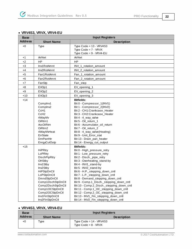
· VRV4S3, VRVX, VRV4-EU
Base Address
Input Registers
Short Name Description
+0 Type Type Code = 13 - VRV4S3Type Code = 7 - VRVXType Code = 9 - VRV4-EU
+1 AirNet AirNet
+2 HP HP
+3 Inv1RotAmnt INV_1_rotation_amount
+4 Inv2RotAmnt INV_2_rotation_amount
+5 Fan1RotAmnt Fan_1_rotation_amount
+6 Fan2RotAmnt Fan_2_rotation_amount
+7 FanStp Fan_step
+8 EVOp1 EV_opening_1
+9 EVOp2 EV_opening_2
+10 EVOp3 EV_opening_3
+14CompInv1CompInv2CcH1CcH24WayVlvOiRtrn1AccOiRtrnOiRtrn24WayVlvHeatErrStateDrnPanHtrEnrgyCutOutp
Bitfields:Bit 0 - Compressor_1(INV1)Bit 1 - Compressor_2(INV2)Bit 2 - CH1:Crankcase_HeaterBit 3 - CH2:Crankcase_HeaterBit 4 - 4_way_valveBit 5 - Oil_return_1Bit 6 - Accumulator_oil_returnBit 7 - Oil_return_2Bit 8 - 4_way_valve(Heating)Bit 9 - Unit_Error_statBit 13 - Drain_pan_heaterBit 14 - Energy_cut_output
+15HiPRtryLoPRtryDischPipRtryOHStbyInv1StbyInv2StbyHiPStpDnCtlLoPStpDnCtlDmndStpDnCtlComp1DschStpDnCtlComp2DschStpDnCtlComp1OCStpDnCtlComp2OCStpDnCtlInv1FinStpDnCtlInv2FinStpDnCtl
Bitfields:Bit 0 - High_pressure_retryBit 1 - Low_pressure_retryBit 2 - Disch._pipe_retryBit 3 - Overheating_stand-byBit 4 - INV1_stand-byBit 5 - INV2_stand-byBit 6 - H.P._stepping_down_cntlBit 7 - L.P._stepping_down_cntlBit 8 - Demand_stepping_down_cntlBit 9 - Comp.1_Disch._stepping_down_cntlBit 10 - Comp.2_Disch._stepping_down_cntlBit 11 - Comp.1_OC_stepping_down_cntlBit 12 - Comp.2_OC_stepping_down_cntlBit 13 - INV1_Fin_stepping_down_cntlBit 14 - INV2_Fin_stepping_down_cntl
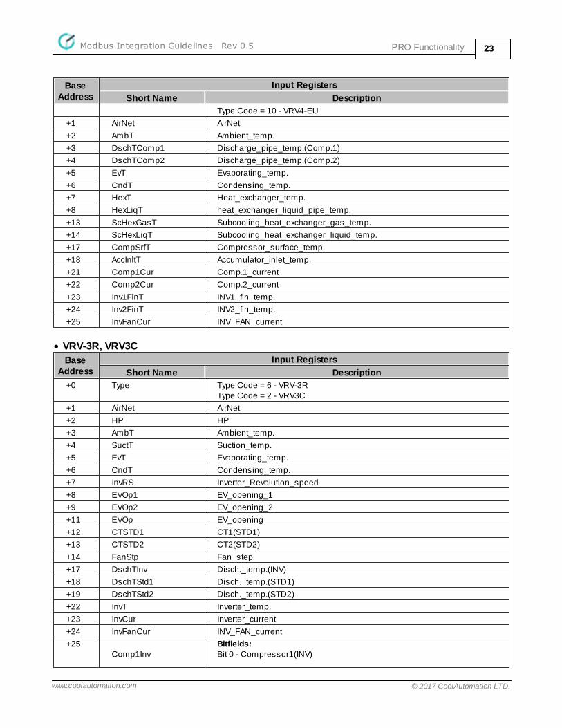
· VRV4S3, VRVX, VRV4-EU
Base Address
Input Registers
Short Name Description
+0 Type Type Code = 14 - VRV4S3Type Code = 8 - VRVX
PRO FunctionalityModbus Integration Guidelines Rev 0.5 23
www.coolautomation.com © 2017 CoolAutomation LTD.
Base Address
Input Registers
Short Name Description
Type Code = 10 - VRV4-EU
+1 AirNet AirNet
+2 AmbT Ambient_temp.
+3 DschTComp1 Discharge_pipe_temp.(Comp.1)
+4 DschTComp2 Discharge_pipe_temp.(Comp.2)
+5 EvT Evaporating_temp.
+6 CndT Condensing_temp.
+7 HexT Heat_exchanger_temp.
+8 HexLiqT heat_exchanger_liquid_pipe_temp.
+13 ScHexGasT Subcooling_heat_exchanger_gas_temp.
+14 ScHexLiqT Subcooling_heat_exchanger_liquid_temp.
+17 CompSrfT Compressor_surface_temp.
+18 AccInltT Accumulator_inlet_temp.
+21 Comp1Cur Comp.1_current
+22 Comp2Cur Comp.2_current
+23 Inv1FinT INV1_fin_temp.
+24 Inv2FinT INV2_fin_temp.
+25 InvFanCur INV_FAN_current
· VRV-3R, VRV3C
Base Address
Input Registers
Short Name Description
+0 Type Type Code = 6 - VRV-3RType Code = 2 - VRV3C
+1 AirNet AirNet
+2 HP HP
+3 AmbT Ambient_temp.
+4 SuctT Suction_temp.
+5 EvT Evaporating_temp.
+6 CndT Condensing_temp.
+7 InvRS Inverter_Revolution_speed
+8 EVOp1 EV_opening_1
+9 EVOp2 EV_opening_2
+11 EVOp EV_opening
+12 CTSTD1 CT1(STD1)
+13 CTSTD2 CT2(STD2)
+14 FanStp Fan_step
+17 DschTInv Disch._temp.(INV)
+18 DschTStd1 Disch._temp.(STD1)
+19 DschTStd2 Disch._temp.(STD2)
+22 InvT Inverter_temp.
+23 InvCur Inverter_current
+24 InvFanCur INV_FAN_current
+25Comp1Inv
Bitfields:Bit 0 - Compressor1(INV)
PRO FunctionalityModbus Integration Guidelines Rev 0.5 24
www.coolautomation.com © 2017 CoolAutomation LTD.
Base Address
Input Registers
Short Name Description
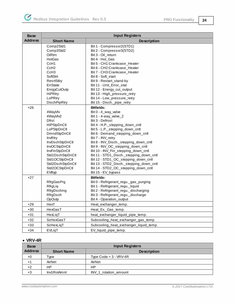
Comp2Std1Comp3Std2OiRtrnHotGasCcH1CcH2CcH3SoftStrtResrtStbyErrStateEnrgyCutOutpHiPRtryLoPRtryDischPipRtry
Bit 1 - Compressor2(STD1)Bit 2 - Compressor3(STD2)Bit 3 - Oil_returnBit 4 - Hot_GasBit 5 - CH1:Crankcase_HeaterBit 6 - CH2:Crankcase_HeaterBit 7 - CH3:Crankcase_HeaterBit 8 - Soft_startBit 9 - Restart_stand-byBit 11 - Unit_Error_statBit 12 - Energy_cut_outputBit 13 - High_pressure_retryBit 14 - Low_pressure_retryBit 15 - Disch._pipe_retry
+264WayVlv4WayVlv2DfrstHiPStpDnCtlLoPStpDnCtlDmndStpDnCtlInvRtryInvDschStpDnCtlInvOCStpDnCtlInvFinStpDnCtlStd1DschStpDnCtlStd1OCStpDnCtlStd2DschStpDnCtlStd2OCStpDnCtlEVByp
Bitfields:Bit 0 - 4_way_valveBit 1 - 4-way_valve_2Bit 3 - DefrostBit 4 - H.P._stepping_down_cntlBit 5 - L.P._stepping_down_cntlBit 6 - Demand_stepping_down_cntlBit 7 - INV_retryBit 8 - INV_Disch._stepping_down_cntlBit 9 - INV_OC_stepping_down_cntlBit 10 - INV_Fin_stepping_down_cntlBit 11 - STD1_Disch._stepping_down_cntlBit 12 - STD1_OC_stepping_down_cntlBit 13 - STD2_Disch._stepping_down_cntlBit 14 - STD2_OC_stepping_down_cntlBit 15 - EV_bypass
+27RfrgGasPrgRfrgLiqRfrgDschingRfrgDschOpOutp
Bitfields:Bit 0 - Refrigerant_regu._gas_purgingBit 1 - Refrigerant_regu._liquidBit 2 - Refrigerant_regu._dischargingBit 3 - Refrigerant_regu._dischargeBit 4 - Oparation_output
+29 HexT Heat_exchanger_temp.
+30 HexGasT Heat_Ex._Gas_temp.
+31 HexLiqT heat_exchanger_liquid_pipe_temp.
+32 ScHexGasT Subcooling_heat_exchanger_gas_temp.
+33 ScHexLiqT Subcooling_heat_exchanger_liquid_temp.
+34 EVLiqT EV_liquid_pipe_temp.
· VRV-4R
Base Address
Input Registers
Short Name Description
+0 Type Type Code = 3 - VRV-4R
+1 AirNet AirNet
+2 HP HP
+3 Inv1RotAmnt INV_1_rotation_amount

PRO FunctionalityModbus Integration Guidelines Rev 0.5 25
www.coolautomation.com © 2017 CoolAutomation LTD.
Base Address
Input Registers
Short Name Description
+4 Inv2RotAmnt INV_2_rotation_amount
+5 Fan1RotAmnt Fan_1_rotation_amount
+6 Fan2RotAmnt Fan_2_rotation_amount
+7 FanStp Fan_step
+8 EVOp1 EV_opening_1
+9 EVOp2 EV_opening_2
+10 EVOp3 EV_opening_3
+11 EVOp4 EV4_pls.(receiver_gas_purge)
+12 EVOp5 EV5_pls.(cooling_refrigant)
+13 EVOp6 EV6_pls.(leak_detection)
+14CompInv1CompInv2CcH1CcH24WayVlvOiRtrn1OiRtrn2ErrState4WayVlvUpr4WayVlvUndrSolVlvDrnPanHtrEnrgyCutOutp
Bitfields:Bit 0 - Compressor_1(INV1)Bit 1 - Compressor_2(INV2)Bit 2 - CH1:Crankcase_HeaterBit 3 - CH2:Crankcase_HeaterBit 4 - 4_way_valveBit 5 - Oil_return_1Bit 7 - Oil_return_2Bit 9 - Unit_Error_statBit 10 - 4-way_valve(upper_heat_exchanger)Bit 11 - 4-way_valve(under_heat_exchanger)Bit 12 - sol._valve(shutoff_liquid_pipe)Bit 13 - Drain_pan_heaterBit 14 - Energy_cut_output
+15HiPRtryLoPRtryDischPipRtryOHStbyInv1StbyInv2StbyHiPStpDnCtlLoPStpDnCtlDmndStpDnCtlComp1DschStpDnCtlComp2DschStpDnCtlComp1OCStpDnCtlComp2OCStpDnCtlInv1FinStpDnCtlInv2FinStpDnCtl
Bitfields:Bit 0 - High_pressure_retryBit 1 - Low_pressure_retryBit 2 - Disch._pipe_retryBit 3 - Overheating_stand-byBit 4 - INV1_stand-byBit 5 - INV2_stand-byBit 6 - H.P._stepping_down_cntlBit 7 - L.P._stepping_down_cntlBit 8 - Demand_stepping_down_cntlBit 9 - Comp.1_Disch._stepping_down_cntlBit 10 - Comp.2_Disch._stepping_down_cntlBit 11 - Comp.1_OC_stepping_down_cntlBit 12 - Comp.2_OC_stepping_down_cntlBit 13 - INV1_Fin_stepping_down_cntlBit 14 - INV2_Fin_stepping_down_cntl
· VRV-4R
Base Address
Input Registers
Short Name Description
+0 Type Type Code = 4 - VRV-4R
+1 AirNet AirNet
+2 AmbT Ambient_temp.
+3 DschTComp1 Discharge_pipe_temp.(Comp.1)
+4 DschTComp2 Discharge_pipe_temp.(Comp.2)
PRO FunctionalityModbus Integration Guidelines Rev 0.5 26
www.coolautomation.com © 2017 CoolAutomation LTD.
Base Address
Input Registers
Short Name Description
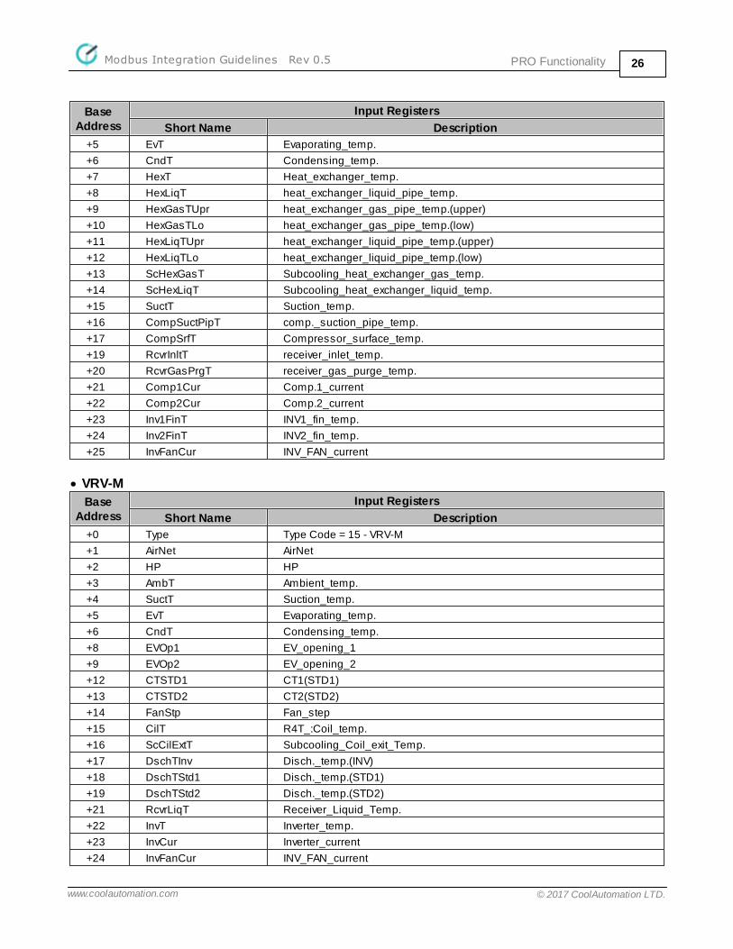
+5 EvT Evaporating_temp.
+6 CndT Condensing_temp.
+7 HexT Heat_exchanger_temp.
+8 HexLiqT heat_exchanger_liquid_pipe_temp.
+9 HexGasTUpr heat_exchanger_gas_pipe_temp.(upper)
+10 HexGasTLo heat_exchanger_gas_pipe_temp.(low)
+11 HexLiqTUpr heat_exchanger_liquid_pipe_temp.(upper)
+12 HexLiqTLo heat_exchanger_liquid_pipe_temp.(low)
+13 ScHexGasT Subcooling_heat_exchanger_gas_temp.
+14 ScHexLiqT Subcooling_heat_exchanger_liquid_temp.
+15 SuctT Suction_temp.
+16 CompSuctPipT comp._suction_pipe_temp.
+17 CompSrfT Compressor_surface_temp.
+19 RcvrInltT receiver_inlet_temp.
+20 RcvrGasPrgT receiver_gas_purge_temp.
+21 Comp1Cur Comp.1_current
+22 Comp2Cur Comp.2_current
+23 Inv1FinT INV1_fin_temp.
+24 Inv2FinT INV2_fin_temp.
+25 InvFanCur INV_FAN_current
· VRV-M
Base Address
Input Registers
Short Name Description
+0 Type Type Code = 15 - VRV-M
+1 AirNet AirNet
+2 HP HP
+3 AmbT Ambient_temp.
+4 SuctT Suction_temp.
+5 EvT Evaporating_temp.
+6 CndT Condensing_temp.
+8 EVOp1 EV_opening_1
+9 EVOp2 EV_opening_2
+12 CTSTD1 CT1(STD1)
+13 CTSTD2 CT2(STD2)
+14 FanStp Fan_step
+15 CilT R4T_:Coil_temp.
+16 ScCilExtT Subcooling_Coil_exit_Temp.
+17 DschTInv Disch._temp.(INV)
+18 DschTStd1 Disch._temp.(STD1)
+19 DschTStd2 Disch._temp.(STD2)
+21 RcvrLiqT Receiver_Liquid_Temp.
+22 InvT Inverter_temp.
+23 InvCur Inverter_current
+24 InvFanCur INV_FAN_current
PRO FunctionalityModbus Integration Guidelines Rev 0.5 27
www.coolautomation.com © 2017 CoolAutomation LTD.
Base Address
Input Registers
Short Name Description
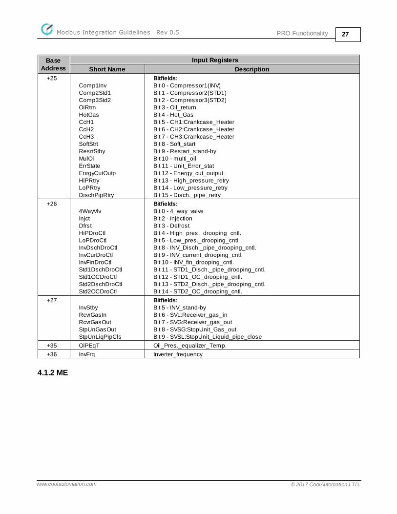
+25Comp1InvComp2Std1Comp3Std2OiRtrnHotGasCcH1CcH2CcH3SoftStrtResrtStbyMulOiErrStateEnrgyCutOutpHiPRtryLoPRtryDischPipRtry
Bitfields:Bit 0 - Compressor1(INV)Bit 1 - Compressor2(STD1)Bit 2 - Compressor3(STD2)Bit 3 - Oil_returnBit 4 - Hot_GasBit 5 - CH1:Crankcase_HeaterBit 6 - CH2:Crankcase_HeaterBit 7 - CH3:Crankcase_HeaterBit 8 - Soft_startBit 9 - Restart_stand-byBit 10 - multi_oilBit 11 - Unit_Error_statBit 12 - Energy_cut_outputBit 13 - High_pressure_retryBit 14 - Low_pressure_retryBit 15 - Disch._pipe_retry
+264WayVlvInjctDfrstHiPDroCtlLoPDroCtlInvDschDroCtlInvCurDroCtlInvFinDroCtlStd1DschDroCtlStd1OCDroCtlStd2DschDroCtlStd2OCDroCtl
Bitfields:Bit 0 - 4_way_valveBit 2 - InjectionBit 3 - DefrostBit 4 - High_pres._drooping_cntl.Bit 5 - Low_pres._drooping_cntl.Bit 8 - INV_Disch._pipe_drooping_cntl.Bit 9 - INV_current_drooping_cntl.Bit 10 - INV_fin_drooping_cntl.Bit 11 - STD1_Disch._pipe_drooping_cntl.Bit 12 - STD1_OC_drooping_cntl.Bit 13 - STD2_Disch._pipe_drooping_cntl.Bit 14 - STD2_OC_drooping_cntl.
+27InvStbyRcvrGasInRcvrGasOutStpUnGasOutStpUnLiqPipCls
Bitfields:Bit 5 - INV_stand-byBit 6 - SVL:Receiver_gas_inBit 7 - SVG:Receiver_gas_outBit 8 - SVSG:StopUnit_Gas_outBit 9 - SVSL:StopUnit_Liquid_pipe_close
+35 OiPEqT Oil_Pres._equalizer_Temp.
+36 InvFrq Inverter_frequency
4.1.2 ME

PRO FunctionalityModbus Integration Guidelines Rev 0.5 28
www.coolautomation.com © 2017 CoolAutomation LTD.
4.1.2.1 ME PRO Indoor Units
Base Address
Input Registers
+0 Type Code = 0x80FF Type Code = 0x800C
+1 TH1*10 TH1
+2 TH2*10 TH2
+3 TH3*10 TH3
+4 TH4
+5 SH*10 TH5
+6 SC*10 TH6
+7 Li TH7
+8 TH8
+9 Fan
+10 Hz
+11 SC*10
+12 LevA
+13 LevB
4.1.2.2 ME PRO Outdoor Units
· PUMY-P100-140Y/VHM/36-48NHMU Type code: 1
Base Address
Input Registers
+0 Type Code = 1
+3 TH3
+4 TH4
+6 TH6
+7 TH7
+8 TH8
+13 63HS
+20 Vdc
+21 Ii
+22 Ic
+25 F(Hz)
+26 FAN
+28 Pdm
+29 ETm
+32 SC
+33 SCm
+37 LEV1
+38 LEV2
+39 LEV3
+40 LEV4
PRO FunctionalityModbus Integration Guidelines Rev 0.5 29
www.coolautomation.com © 2017 CoolAutomation LTD.
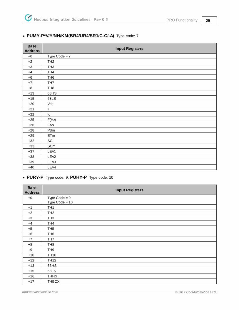
· PUMY-P*V/Y/NH/KM(BR4/UR4/SR1/C-C/-A) Type code: 7
Base Address
Input Registers
+0 Type Code = 7
+2 TH2
+3 TH3
+4 TH4
+6 TH6
+7 TH7
+8 TH8
+13 63HS
+15 63LS
+20 Vdc
+21 Ii
+22 Ic
+25 F(Hz)
+26 FAN
+28 Pdm
+29 ETm
+32 SC
+33 SCm
+37 LEV1
+38 LEV2
+39 LEV3
+40 LEV4
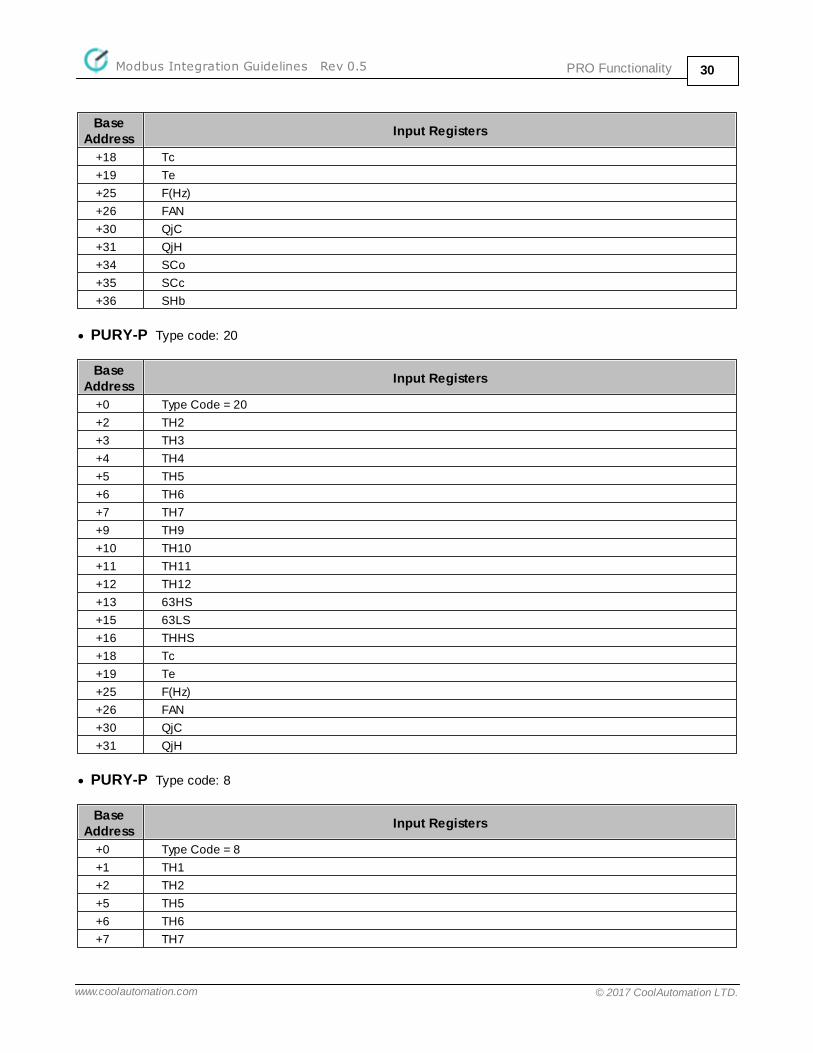
· PURY-P Type code: 9, PUHY-P Type code: 10
Base Address
Input Registers
+0 Type Code = 9Type Code = 10
+1 TH1
+2 TH2
+3 TH3
+4 TH4
+5 TH5
+6 TH6
+7 TH7
+8 TH8
+9 TH9
+10 TH10
+12 TH12
+13 63HS
+15 63LS
+16 THHS
+17 THBOX
PRO FunctionalityModbus Integration Guidelines Rev 0.5 30
www.coolautomation.com © 2017 CoolAutomation LTD.
Base Address
Input Registers
+18 Tc
+19 Te
+25 F(Hz)
+26 FAN
+30 QjC
+31 QjH
+34 SCo
+35 SCc
+36 SHb
· PURY-P Type code: 20
Base Address
Input Registers
+0 Type Code = 20
+2 TH2
+3 TH3
+4 TH4
+5 TH5
+6 TH6
+7 TH7
+9 TH9
+10 TH10
+11 TH11
+12 TH12
+13 63HS
+15 63LS
+16 THHS
+18 Tc
+19 Te
+25 F(Hz)
+26 FAN
+30 QjC
+31 QjH
· PURY-P Type code: 8
Base Address
Input Registers
+0 Type Code = 8
+1 TH1
+2 TH2
+5 TH5
+6 TH6
+7 TH7

PRO FunctionalityModbus Integration Guidelines Rev 0.5 31
www.coolautomation.com © 2017 CoolAutomation LTD.
Base Address
Input Registers
+13 63HS
+15 63LS
+16 THHS
+18 Tc
+19 Te
+20 Vdc
+23 Iu
+24 Iw
+25 F(Hz)
+26 FAN
+30 QjC
+31 QjH
· PURY-P Type code: 3
Base Address
Input Registers
+0 Type Code = 3
+5 TH5
+6 TH6
+7 TH7
+11 TH11
+13 63HS
+15 63LS
+18 Tc
+19 Te
+20 Vdc
+23 Iu
+24 Iw
+25 F(Hz)
+26 FAN
+30 QjC
+31 QjH
+34 SCo
+35 SCc
+36 SHb
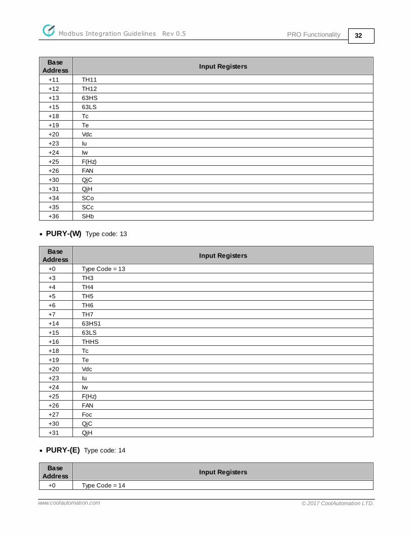
· PURY-P Type code: 2
Base Address
Input Registers
+0 Type Code = 2
+5 TH5
+6 TH6
+7 TH7
PRO FunctionalityModbus Integration Guidelines Rev 0.5 32
www.coolautomation.com © 2017 CoolAutomation LTD.
Base Address
Input Registers
+11 TH11
+12 TH12
+13 63HS
+15 63LS
+18 Tc
+19 Te
+20 Vdc
+23 Iu
+24 Iw
+25 F(Hz)
+26 FAN
+30 QjC
+31 QjH
+34 SCo
+35 SCc
+36 SHb
· PURY-(W) Type code: 13
Base Address
Input Registers
+0 Type Code = 13
+3 TH3
+4 TH4
+5 TH5
+6 TH6
+7 TH7
+14 63HS1
+15 63LS
+16 THHS
+18 Tc
+19 Te
+20 Vdc
+23 Iu
+24 Iw
+25 F(Hz)
+26 FAN
+27 Foc
+30 QjC
+31 QjH
· PURY-(E) Type code: 14
Base Address
Input Registers
+0 Type Code = 14

PRO FunctionalityModbus Integration Guidelines Rev 0.5 33
www.coolautomation.com © 2017 CoolAutomation LTD.
Base Address
Input Registers
+3 TH3
+4 TH4
+5 TH5
+6 TH6
+7 TH7
+14 63HS1
+15 63LS
+16 THHS
+18 Tc
+19 Te
+20 Vdc
+23 Iu
+24 Iw
+26 FAN
+27 Foc
+30 QjC
+31 QjH
· PURY-P YLM-A Type code: 12
Base Address
Input Registers
+0 Type Code = 12
+3 TH3
+4 TH4
+5 TH5
+6 TH6
+7 TH7
+9 TH9
+11 TH11
+14 63HS1
+15 63LS
+16 THHS
+18 Tc
+19 Te
+20 Vdc
+23 Iu
+24 Iw
+25 F(Hz)
+26 FAN
+27 Foc
+30 QjC
+31 QjH
· PUHY-P YKB Type code: 19

PRO FunctionalityModbus Integration Guidelines Rev 0.5 34
www.coolautomation.com © 2017 CoolAutomation LTD.
Base Address
Input Registers
+0 Type Code = 19
+2 TH2
+3 TH3
+4 TH4
+5 TH5
+6 TH6
+7 TH7
+9 TH9
+11 TH11
+14 63HS1
+15 63LS
+16 THHS
+18 Tc
+19 Te
+20 Vdc
+23 Iu
+24 Iw
+25 F(Hz)
+26 FAN
+27 Foc
+30 QjC
+31 QjH
+34 SCo
+35 SCc
+36 SHb
+37 LEV1
· PUHY-(E)P Type code: 5
Base Address
Input Registers
+0 Type Code = 5
+2 TH2
+3 TH3
+4 TH4
+5 TH5
+6 TH6
+7 TH7
+14 63HS1
+15 63LS
+16 THHS
+18 Tc
+19 Te
+20 Vdc
+23 Iu

PRO FunctionalityModbus Integration Guidelines Rev 0.5 35
www.coolautomation.com © 2017 CoolAutomation LTD.
Base Address
Input Registers
+24 Iw
+25 F(Hz)
+26 FAN
+27 Foc
+30 QjC
+31 QjH
+34 SCo
+35 SCc
+36 SHb
· PUHY-(E)P Type code: 17
Base Address
Input Registers
+0 Type Code = 17
+2 TH2
+3 TH3
+4 TH4
+5 TH5
+6 TH6
+7 TH7
+14 63HS1
+15 63LS
+16 THHS
+17 THBOX
+18 Tc
+19 Te
+20 Vdc
+23 Iu
+24 Iw
+25 F(Hz)
+26 FAN
+27 Foc
+30 QjC
+31 QjH
+34 SCo
+35 SCc
+36 SHb
+37 LEV1
+38 LEV2
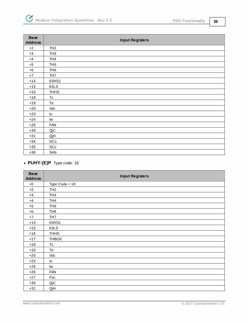
· PUHY-(E)P Type code: 6
Base Address
Input Registers
+0 Type Code = 6
PRO FunctionalityModbus Integration Guidelines Rev 0.5 36
www.coolautomation.com © 2017 CoolAutomation LTD.
Base Address
Input Registers
+2 TH2
+3 TH3
+4 TH4
+5 TH5
+6 TH6
+7 TH7
+14 63HS1
+15 63LS
+16 THHS
+18 Tc
+19 Te
+20 Vdc
+23 Iu
+24 Iw
+26 FAN
+30 QjC
+31 QjH
+34 SCo
+35 SCc
+36 SHb
· PUHY-(E)P Type code: 18
Base Address
Input Registers
+0 Type Code = 18
+2 TH2
+3 TH3
+4 TH4
+5 TH5
+6 TH6
+7 TH7
+14 63HS1
+15 63LS
+16 THHS
+17 THBOX
+18 Tc
+19 Te
+20 Vdc
+23 Iu
+24 Iw
+26 FAN
+27 Foc
+30 QjC
+31 QjH
PRO FunctionalityModbus Integration Guidelines Rev 0.5 37
www.coolautomation.com © 2017 CoolAutomation LTD.
Base Address
Input Registers
+34 SCo
+35 SCc
+36 SHb
+37 LEV1
+38 LEV2
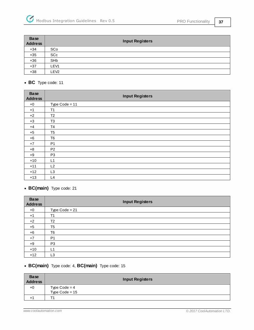
· BC Type code: 11
Base Address
Input Registers
+0 Type Code = 11
+1 T1
+2 T2
+3 T3
+4 T4
+5 T5
+6 T6
+7 P1
+8 P2
+9 P3
+10 L1
+11 L2
+12 L3
+13 L4
· BC(main) Type code: 21
Base Address
Input Registers
+0 Type Code = 21
+1 T1
+2 T2
+5 T5
+6 T6
+7 P1
+9 P3
+10 L1
+12 L3
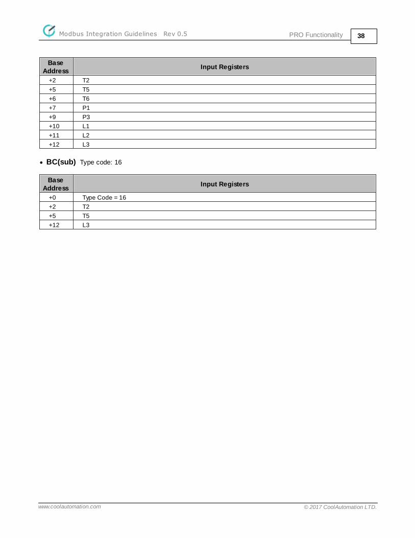
· BC(main) Type code: 4, BC(main) Type code: 15
Base Address
Input Registers
+0 Type Code = 4Type Code = 15
+1 T1
PRO FunctionalityModbus Integration Guidelines Rev 0.5 38
www.coolautomation.com © 2017 CoolAutomation LTD.
Base Address
Input Registers
+2 T2
+5 T5
+6 T6
+7 P1
+9 P3
+10 L1
+11 L2
+12 L3
· BC(sub) Type code: 16
Base Address
Input Registers
+0 Type Code = 16
+2 T2
+5 T5
+12 L3

Commands ReferenceModbus Integration Guidelines Rev 0.5 39
www.coolautomation.com © 2017 CoolAutomation LTD.
5 Commands Reference
line
modbus
va
5.1 lineSYNOPSIS
line
line type <Ln> <TYPE>
line myid <Ln> <SA>
line baud <Ln> <FRAME>
DESCRIPTION
<Ln> parameter denotes communication line number like for example: L3 or L4.
· Without parameters line command prints status of all communication lines available in specific device.
· line type command is used to activate Modbus RTU module on line <Ln>. <TYPE> parameter can be CG5 or
CG4 (see Legacy CoolGate Mode) for CoolMasterNet device and CLMB for CooLinkNet device.
· line myid command will change Modbus Slave Address of the Modbus RTU module running on line <Ln>.
Parameter <SA> is a new Modbus Slave Address in hexadecimal format. Accepted range of addresses is 01..F7
. New address will be in use after power reset.
· line baud command is used to change Modbus RTU frame format for line <Ln>. <FRAME> parameter format is
<BAUD>_<8|9><N|E|O><1|2>. Supported baud rates for <BAUD> parameter are: 1200, 2400, 4800, 9600, 19200,
38400, 57600, 115200. Frame format change is effective only after power reset.
EXAMPLE
See examples in Modbus RTU Configuration chapter.
5.2 modbusSYNOPSIS
modbus
modbus IP <enable|disable>
modbus server port <PORT>
modbus ignore r
modbus cg4
DESCRIPTION
This command is available only in CoolMasterNet device.· Without parameters modbus command prints status of the Modbus IP Server.
· modbus IP command is used to enable or disable Modbus IP activation.
· modbus server port command will change Modbus IP Server TCPI/IP port number. New port number will be
effective only after power reset.· modbus ignore r command will toggle ignore flag used by Modbus RTU module in attempt to access non
implemented holding or input register. If ignore flag is set, attempt to access non existing register(s) will not
Commands ReferenceModbus Integration Guidelines Rev 0.5 40
www.coolautomation.com © 2017 CoolAutomation LTD.
cause the "Illegal Data Address" Modbus exception. This feature enables accessing of the multiple registersblock with gap(s).
· modbus cg4 command is used for legacy CoolGate Modbus RTU operation mode (see Legacy CoolGate Mode).
It prints relation between detected UID's and CoolGate Modbus objects Base Addresses.
EXAMPLE
See examples in Modbus IP Configuration chapter.
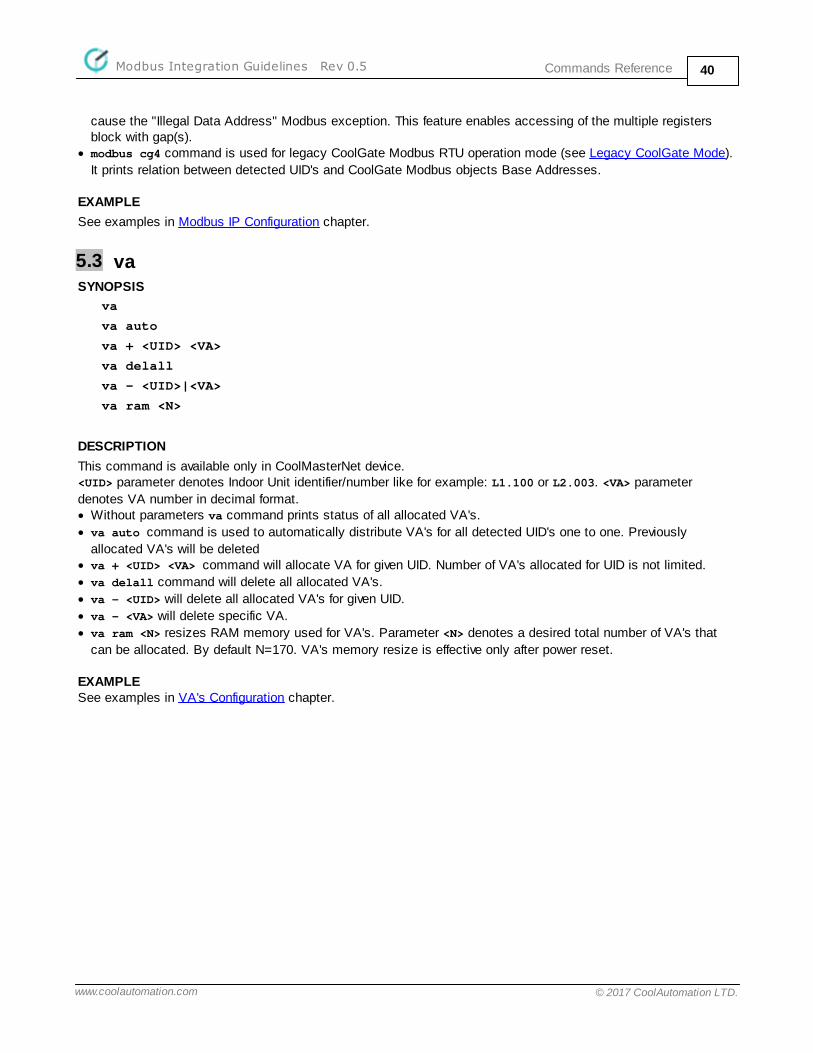
5.3 vaSYNOPSIS
va
va auto
va + <UID> <VA>
va delall
va - <UID>|<VA>
va ram <N>
DESCRIPTION
This command is available only in CoolMasterNet device.<UID> parameter denotes Indoor Unit identifier/number like for example: L1.100 or L2.003. <VA> parameter
denotes VA number in decimal format. · Without parameters va command prints status of all allocated VA's.
· va auto command is used to automatically distribute VA's for all detected UID's one to one. Previously
allocated VA's will be deleted· va + <UID> <VA> command will allocate VA for given UID. Number of VA's allocated for UID is not limited.
· va delall command will delete all allocated VA's.
· va - <UID> will delete all allocated VA's for given UID.
· va - <VA> will delete specific VA.
· va ram <N> resizes RAM memory used for VA's. Parameter <N> denotes a desired total number of VA's that
can be allocated. By default N=170. VA's memory resize is effective only after power reset.
EXAMPLESee examples in VA's Configuration chapter.
Legacy CoolGate ModeModbus Integration Guidelines Rev 0.5 41
www.coolautomation.com © 2017 CoolAutomation LTD.
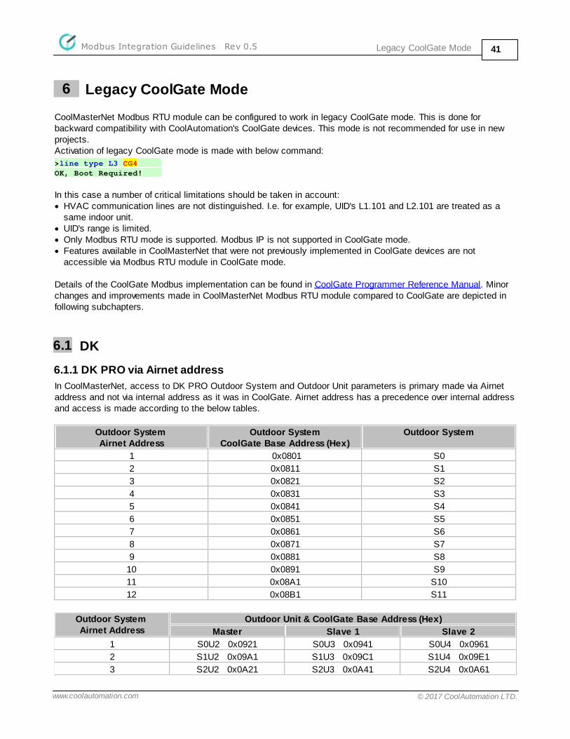
6 Legacy CoolGate Mode
CoolMasterNet Modbus RTU module can be configured to work in legacy CoolGate mode. This is done forbackward compatibility with CoolAutomation's CoolGate devices. This mode is not recommended for use in newprojects. Activation of legacy CoolGate mode is made with below command:
>line type L3 CG4
OK, Boot Required!
In this case a number of critical limitations should be taken in account:· HVAC communication lines are not distinguished. I.e. for example, UID's L1.101 and L2.101 are treated as a
same indoor unit.· UID's range is limited.· Only Modbus RTU mode is supported. Modbus IP is not supported in CoolGate mode.· Features available in CoolMasterNet that were not previously implemented in CoolGate devices are not
accessible via Modbus RTU module in CoolGate mode.
Details of the CoolGate Modbus implementation can be found in CoolGate Programmer Reference Manual. Minorchanges and improvements made in CoolMasterNet Modbus RTU module compared to CoolGate are depicted infollowing subchapters.
6.1 DK
6.1.1 DK PRO via Airnet address
In CoolMasterNet, access to DK PRO Outdoor System and Outdoor Unit parameters is primary made via Airnetaddress and not via internal address as it was in CoolGate. Airnet address has a precedence over internal addressand access is made according to the below tables.
Outdoor System Airnet Address
Outdoor SystemCoolGate Base Address (Hex)
Outdoor System
1 0x0801 S0
2 0x0811 S1
3 0x0821 S2
4 0x0831 S3
5 0x0841 S4
6 0x0851 S5
7 0x0861 S6
8 0x0871 S7
9 0x0881 S8
10 0x0891 S9
11 0x08A1 S10
12 0x08B1 S11
Outdoor System Airnet Address
Outdoor Unit & CoolGate Base Address (Hex)
Master Slave 1 Slave 2
1 S0U2 0x0921 S0U3 0x0941 S0U4 0x0961
2 S1U2 0x09A1 S1U3 0x09C1 S1U4 0x09E1
3 S2U2 0x0A21 S2U3 0x0A41 S2U4 0x0A61
Legacy CoolGate ModeModbus Integration Guidelines Rev 0.5 42
www.coolautomation.com © 2017 CoolAutomation LTD.
4 S3U2 0x0AA1 S3U3 0x0AC1 S3U4 0x0AE1
5 S4U2 0x0B21 S4U3 0x0B41 S4U4 0x0B61
6 S5U2 0x0BA1 S5U3 0x0BC1 S5U4 0x0BE1
7 S6U2 0x0C21 S6U3 0x0C41 S6U4 0x0C61
8 S7U2 0x0CA1 S7U3 0x0CC1 S7U4 0x0CE1
9 S8U2 0x0D21 S8U3 0x0D41 S8U4 0x0D61
10 S9U2 0x0DA1 S9U3 0x0DC1 S9U4 0x0DE1
11 S10U2 0x0E21 S10U3 0x0E41 S10U4 0x0E61
12 S11U2 0x0EA1 S11U3 0x0EC1 S11U4 0x0EE1
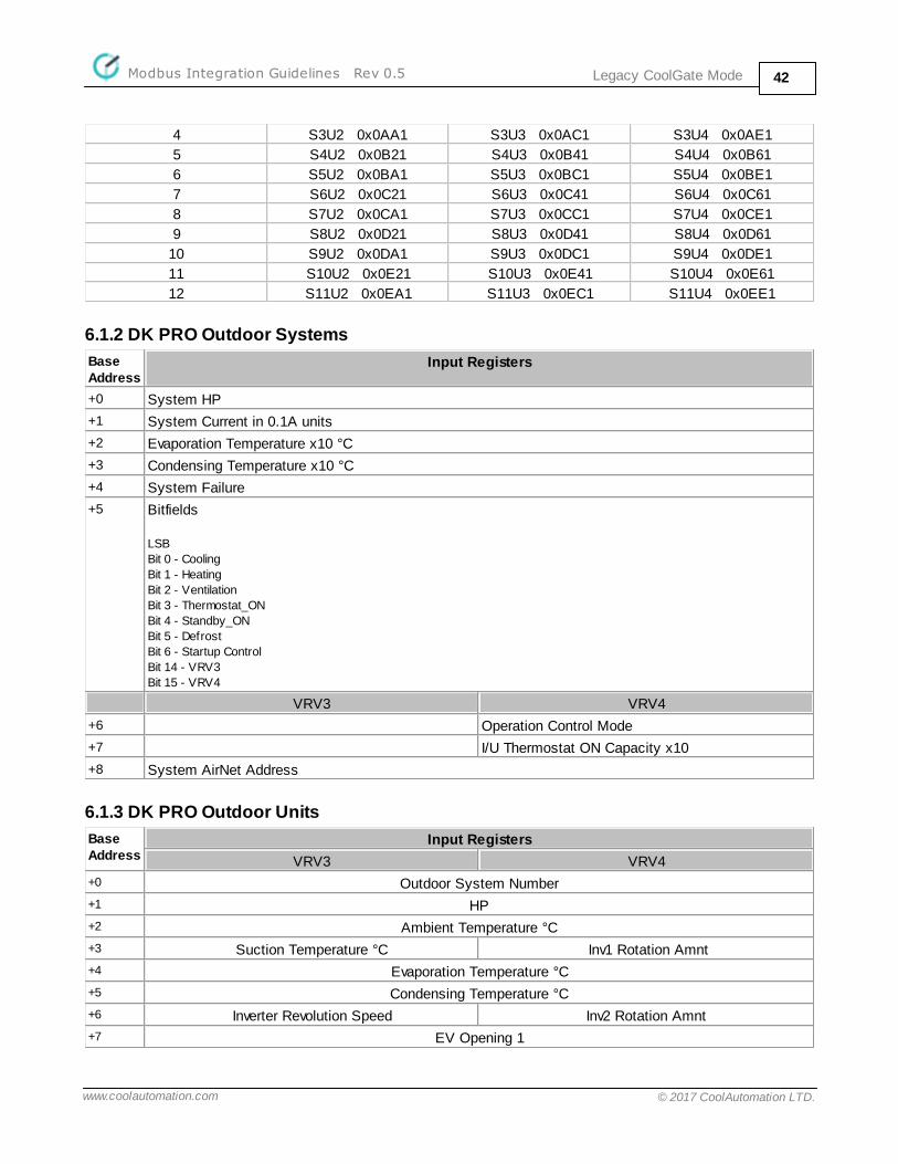
6.1.2 DK PRO Outdoor Systems
Base Address
Input Registers
+0 System HP
+1 System Current in 0.1A units
+2 Evaporation Temperature x10 °C
+3 Condensing Temperature x10 °C
+4 System Failure
+5 Bitfields
LSB
Bit 0 - Cooling
Bit 1 - Heating
Bit 2 - Ventilation
Bit 3 - Thermostat_ON
Bit 4 - Standby_ON
Bit 5 - Defrost
Bit 6 - Startup Control
Bit 14 - VRV3
Bit 15 - VRV4
VRV3 VRV4
+6 Operation Control Mode
+7 I/U Thermostat ON Capacity x10
+8 System AirNet Address
6.1.3 DK PRO Outdoor Units
Base Address
Input Registers
VRV3 VRV4
+0 Outdoor System Number
+1 HP
+2 Ambient Temperature °C
+3 Suction Temperature °C Inv1 Rotation Amnt
+4 Evaporation Temperature °C
+5 Condensing Temperature °C
+6 Inverter Revolution Speed Inv2 Rotation Amnt
+7 EV Opening 1
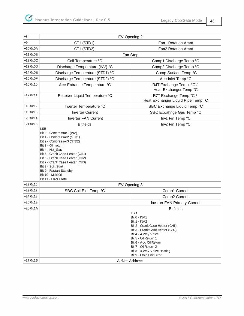
Legacy CoolGate ModeModbus Integration Guidelines Rev 0.5 43
www.coolautomation.com © 2017 CoolAutomation LTD.
+8 EV Opening 2
+9 CT1 (STD1) Fan1 Rotation Amnt
+10 0x0A CT1 (STD2) Fan2 Rotation Amnt
+11 0x0B Fan Step
+12 0x0C Coil Temperature °C Comp1 Discharge Temp °C
+13 0x0D Discharge Temperature (INV) °C Comp2 Discharge Temp °C
+14 0x0E Discharge Temperature (STD1) °C Comp Surface Temp °C
+15 0x0F Discharge Temperature (STD2) °C Acc Inlet Temp °C
+16 0x10 Acc Entrance Temperature °C R4T Exchange Temp °C / Heat Exchanger Temp °C
+17 0x11 Receiver Liquid Temperature °C R7T Exchange Temp °C / Heat Exchanger Liquid Pipe Temp °C
+18 0x12 Inverter Temperature °C SBC Exchange Liquid Temp °C
+19 0x13 Inverter Current SBC Excahnge Gas Temp °C
+20 0x14 Inverter FAN Current Inv1 Fin Temp °C
+21 0x15 BitfieldsLSB
Bit 0 - Compressor1 (INV)
Bit 1 - Compressor2 (STD1)
Bit 2 - Compressor3 (STD2)
Bit 3 - Oil_return
Bit 4 - Hot_Gas
Bit 5 - Crank Case Heater (CH1)
Bit 6 - Crank Case Heater (CH2)
Bit 7 - Crank Case Heater (CH3)
Bit 8 - Soft Start
Bit 9 - Restart Standby
Bit 10 - Multi Oil
Bit 11 - Error State
Inv2 Fin Temp °C
+22 0x16 EV Opening 3
+23 0x17 SBC Coil Exit Temp °C Comp1 Current
+24 0x18 Comp2 Current
+25 0x19 Inverter FAN Primary Current
+26 0x1A BitfieldsLSB
Bit 0 - INV1
Bit 1 - INV2
Bit 2 - Crank Case Heater (CH1)
Bit 3 - Crank Case Heater (CH2)
Bit 4 - 4 Way Valve
Bit 5 - Oil Return 1
Bit 6 - Acc Oil Return
Bit 7 - Oil Return 2
Bit 8 - 4 Way Valve Heating
Bit 9 - Ow n Unit Error
+27 0x1B AirNet Address