modbus analog and digital snap brain - opto...
TRANSCRIPT

Modbus Analog and Digital SNAP Brain
PAGE
1
DA
TA S
HE
ET
Form
10
51
-10
03
04
Mo
db
us A
nalo
g an
d D
igital SN
AP
Brain
Opto 22 • 43044 Business Park Drive • Temecula, CA 92590-3614 • www.opto22.comSALES 800-321-6786 • 951-695-3000 • FAX 951-695-3095 • [email protected] • SUPPORT 800-835-6786 • 951-695-3080 • FAX 951-695-3017 • [email protected]
© 2007 Opto 22. All rights reserved. Dimensions and specifications are subject to change. Brand or product names used herein are trademarks or registered trademarks of their respective companies or organizations.
Features
Controls both analog and digital I/O modules on its rack.
Works with any Modbus master device.
Communicates via RS-485 in ASCII and RTU modes.
Description
With the SNAP-B3000-Modbus brain, you can use reliable Opto 22 industrial I/O hardware with your existing Modbus-compatible controller. The SNAP-B3000-Modbus is a high-performance brain designed to remotely control a mix of both analog and digital I/O modules using the SNAP B-series I/O mounting racks. With SNAP B Series racks and any combination of compatible analog and digital SNAP I/O® modules, this brain provides a powerful and sophisticated I/O handling system. The on-board intelligence of the SNAP-B3000-Modbus offers many distributed control functions.
The SNAP-B3000-MODBUS works with any Modbus master device. The SNAP-B3000-Modbus brain communicates to its master
controller via RS-485 using the Modbus slave protocol in both ASCII and RTU modes. Serial communication from 300 baud to 115,200 baud is supported.
SNAP-B3000-Modbus functions include the following:
• Digital: Input latching, counting (16-bit), and on/off status
• Analog: Thermocouple linearization (16-bit fixed point for lin-earized values)
Part Numbers
Part Description
SNAP-B3000-MODBUS
Analog/Digital Modbus Slave Brain
SNAP-B3000-Modbus

Modbus Analog and Digital SNAP BrainM
od
bu
s A
nal
og
an
d D
igit
al S
NA
P B
rain
PAGE
2
DA
TA S
HE
ET
Form
10
51
-10
03
04
Opto 22 • 43044 Business Park Drive • Temecula, CA 92590-3614 • www.opto22.comSALES 800-321-6786 • 951-695-3000 • FAX 951-695-3095 • [email protected] • SUPPORT 800-835-6786 • 951-695-3080 • FAX 951-695-3017 • [email protected]© 2007 Opto 22. All rights reserved. Dimensions and specifications are subject to change. Brand or product names used herein are trademarks or registered trademarks of their respective companies or organizations.
Description (continued)
SNAP-B3000-Modbus System Architecture
The SNAP-B3000-Modbus is connected to a SNAP B-series I/O rack, which can hold either 8, 12, or 16 SNAP modules.
NOTE: Only one data link is required.
Specifications
Power Requirements 5.0–5.2 VDC at 1.0A max.
Operating Temperature 0 to 70 °C, 95% humidity, non-condensing
Storage Temperature -40 to 85 °C
CPU 16-bit Intel 80C196 I/O processor
Communications Interface RS-485/422, 2- or 4-wire, twisted pair(s), with shield
Data Rates300, 600, 1200, 2400, 4800, 9600, 19200, 38400, 57600, 76800, and 115200 baud
Range: (Multidrop Mode)Up to 3,000 feet total length or 32 stations maximum without repeaters
Counter\Frequency MeasurementMaximum Rate: 20 kHzMinimum Pulse Width: 10 msec16 bit
LED Indicators RUN (Power On), RCV (Receive), and XMT (Transmit)
Options: Jumper Selectable Address, Communication baud rate, RTU/ASCII

Modbus Analog and Digital SNAP BrainM
od
bu
s An
alog
and
Dig
ital SNA
P B
rainD
ATA
SH
EE
T
Form
10
51
-10
03
04
PAGE
3
Opto 22 • 43044 Business Park Drive • Temecula, CA 92590-3614 • www.opto22.comSALES 800-321-6786 • 951-695-3000 • FAX 951-695-3095 • [email protected] • SUPPORT 800-835-6786 • 951-695-3080 • FAX 951-695-3017 • [email protected]
© 2007 Opto 22. All rights reserved. Dimensions and specifications are subject to change. Brand or product names used herein are trademarks or registered trademarks of their respective companies or organizations.
Communication Jumpers/Wiring
Communication Jumper Descriptions
Jumper Description
0 Pull-up for TX/RX+
1 Terminator for TX/RX
2 Pull-down for TX/RX-
3 Pull-up for RX
4 Terminator for RX line
5 Pull-down for RX line
6 Pull-up for IRQ+
7 Terminator for IRQ
8 Pull-down for IRQ-
Top View: SNAP-B3000-Modbus
Modbus Analog and Digital SNAP BrainM
od
bu
s A
nal
og
an
d D
igit
al S
NA
P B
rain
PAGE
4
DA
TA S
HE
ET
Form
10
51
-10
03
04
Opto 22 • 43044 Business Park Drive • Temecula, CA 92590-3614 • www.opto22.comSALES 800-321-6786 • 951-695-3000 • FAX 951-695-3095 • [email protected] • SUPPORT 800-835-6786 • 951-695-3080 • FAX 951-695-3017 • [email protected]© 2007 Opto 22. All rights reserved. Dimensions and specifications are subject to change. Brand or product names used herein are trademarks or registered trademarks of their respective companies or organizations.
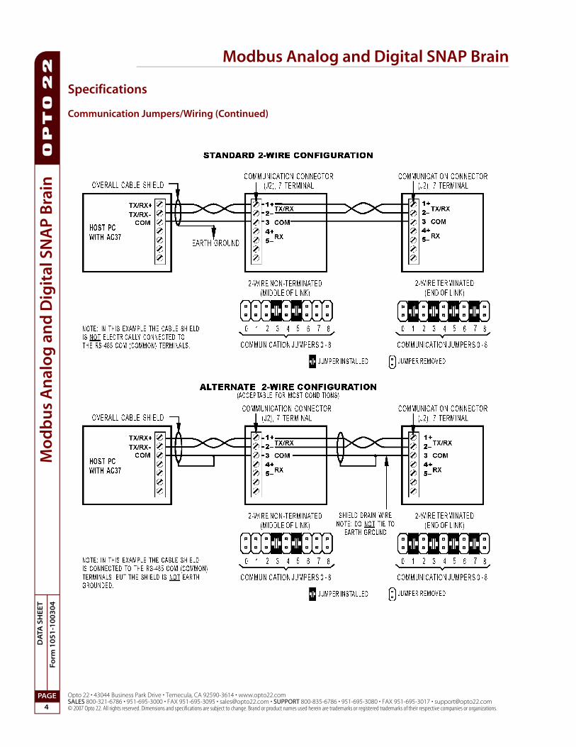
Specifications
Communication Jumpers/Wiring (Continued)
Modbus Analog and Digital SNAP BrainM
od
bu
s An
alog
and
Dig
ital SNA
P B
rainD
ATA
SH
EE
T
Form
10
51
-10
03
04
PAGE
5
Opto 22 • 43044 Business Park Drive • Temecula, CA 92590-3614 • www.opto22.comSALES 800-321-6786 • 951-695-3000 • FAX 951-695-3095 • [email protected] • SUPPORT 800-835-6786 • 951-695-3080 • FAX 951-695-3017 • [email protected]
© 2007 Opto 22. All rights reserved. Dimensions and specifications are subject to change. Brand or product names used herein are trademarks or registered trademarks of their respective companies or organizations.
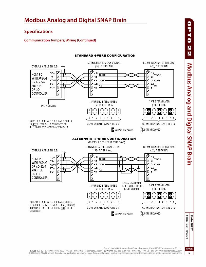
Specifications
Communication Jumpers/Wiring (Continued)

Modbus Analog and Digital SNAP BrainM
od
bu
s A
nal
og
an
d D
igit
al S
NA
P B
rain
PAGE
6
DA
TA S
HE
ET
Form
10
51
-10
03
04
Opto 22 • 43044 Business Park Drive • Temecula, CA 92590-3614 • www.opto22.comSALES 800-321-6786 • 951-695-3000 • FAX 951-695-3095 • [email protected] • SUPPORT 800-835-6786 • 951-695-3080 • FAX 951-695-3017 • [email protected]© 2007 Opto 22. All rights reserved. Dimensions and specifications are subject to change. Brand or product names used herein are trademarks or registered trademarks of their respective companies or organizations.
Specifications
Baud/Address Jumpers, LED Descriptions
Table 3. LED Descriptions
LED Description
RCVProcessor is currently receiving data on communication line.
XMTProcessor is currently transmitting data on communication line.
RUNPower on processor (at least 4.75 VDC)
Table 1: Baud Rate Jumpers
Table 2: Address Table
ASCII Port Modes:7 data bits, 1 stop bit, even parity7 data bits, 1 stop bit, odd parity
RTU Port Modes:8 data bits, 1 stop bit, even parity8 data bits, 1 stop bit, odd parity8 data bits, 1 stop bit, no parity
SNAP-B3000-Modbus Brain
Modbus Analog and Digital SNAP BrainM
od
bu
s An
alog
and
Dig
ital SNA
P B
rainD
ATA
SH
EE
T
Form
10
51
-10
03
04
PAGE
7
Opto 22 • 43044 Business Park Drive • Temecula, CA 92590-3614 • www.opto22.comSALES 800-321-6786 • 951-695-3000 • FAX 951-695-3095 • [email protected] • SUPPORT 800-835-6786 • 951-695-3080 • FAX 951-695-3017 • [email protected]
© 2007 Opto 22. All rights reserved. Dimensions and specifications are subject to change. Brand or product names used herein are trademarks or registered trademarks of their respective companies or organizations.
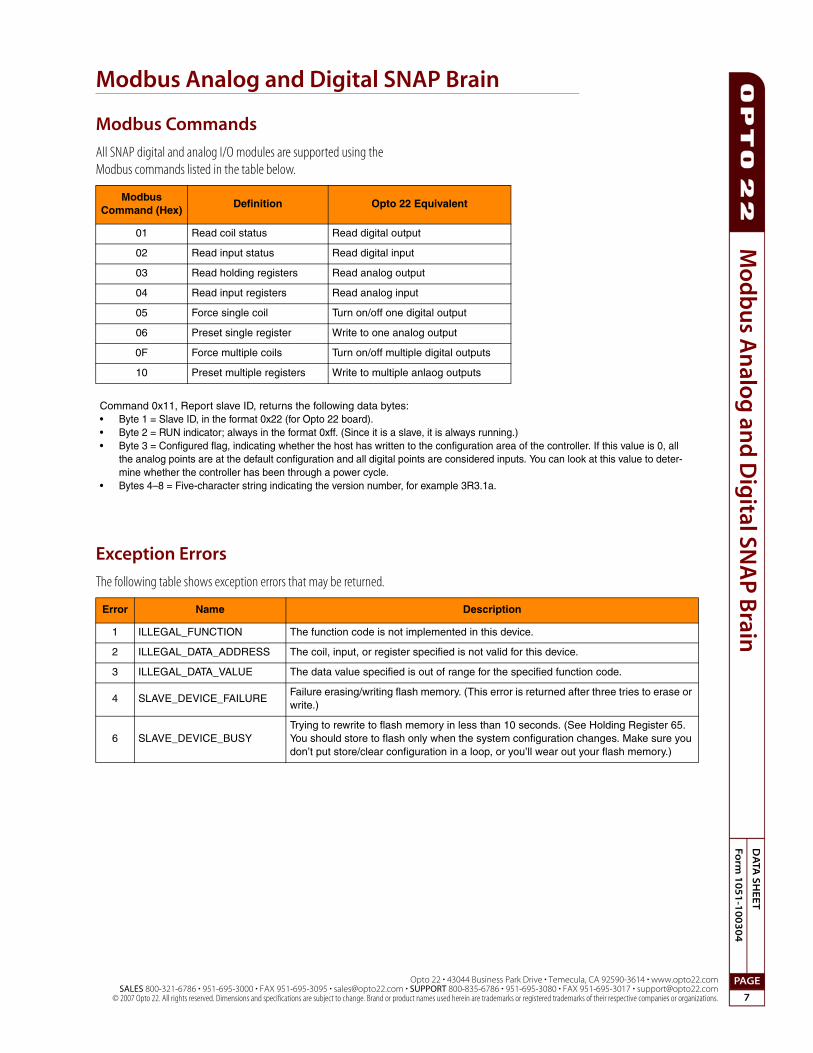
Modbus Commands
All SNAP digital and analog I/O modules are supported using the Modbus commands listed in the table below.
Exception Errors
The following table shows exception errors that may be returned.
Modbus Command (Hex)
Definition Opto 22 Equivalent
01 Read coil status Read digital output
02 Read input status Read digital input
03 Read holding registers Read analog output
04 Read input registers Read analog input
05 Force single coil Turn on/off one digital output
06 Preset single register Write to one analog output
0F Force multiple coils Turn on/off multiple digital outputs
10 Preset multiple registers Write to multiple anlaog outputs
Command 0x11, Report slave ID, returns the following data bytes:• Byte 1 = Slave ID, in the format 0x22 (for Opto 22 board).• Byte 2 = RUN indicator; always in the format 0xff. (Since it is a slave, it is always running.)• Byte 3 = Configured flag, indicating whether the host has written to the configuration area of the controller. If this value is 0, all
the analog points are at the default configuration and all digital points are considered inputs. You can look at this value to deter-mine whether the controller has been through a power cycle.
• Bytes 4–8 = Five-character string indicating the version number, for example 3R3.1a.
Error Name Description
1 ILLEGAL_FUNCTION The function code is not implemented in this device.
2 ILLEGAL_DATA_ADDRESS The coil, input, or register specified is not valid for this device.
3 ILLEGAL_DATA_VALUE The data value specified is out of range for the specified function code.
4 SLAVE_DEVICE_FAILUREFailure erasing/writing flash memory. (This error is returned after three tries to erase or write.)
6 SLAVE_DEVICE_BUSYTrying to rewrite to flash memory in less than 10 seconds. (See Holding Register 65. You should store to flash only when the system configuration changes. Make sure you don’t put store/clear configuration in a loop, or you’ll wear out your flash memory.)

Modbus Analog and Digital SNAP BrainM
od
bu
s A
nal
og
an
d D
igit
al S
NA
P B
rain
PAGE
8
DA
TA S
HE
ET
Form
10
51
-10
03
04
Opto 22 • 43044 Business Park Drive • Temecula, CA 92590-3614 • www.opto22.comSALES 800-321-6786 • 951-695-3000 • FAX 951-695-3095 • [email protected] • SUPPORT 800-835-6786 • 951-695-3080 • FAX 951-695-3017 • [email protected]© 2007 Opto 22. All rights reserved. Dimensions and specifications are subject to change. Brand or product names used herein are trademarks or registered trademarks of their respective companies or organizations.
SNAP-B3000-Modbus I/O Mapping
The largest SNAP B Series I/O rack can contain a maximum of 16 modules. As shown below, the first eight modules can be either digital or analog. The last eight modules can be analog only. Because of the rack’s flexibility in handling both digital and analog inputs and outputs in many of the same module positions, you can choose where to install modules and how to use the points.
Since each digital module contains four points, up to 32 digital I/O points can be installed in the first eight module positions.
Analog input modules contain two points, but analog output modules can have either one or two points, depending on the module. Using all module positions, up to 32 analog I/O points can be installed in the rack.

Modbus Analog and Digital SNAP BrainM
od
bu
s An
alog
and
Dig
ital SNA
P B
rainD
ATA
SH
EE
T
Form
10
51
-10
03
04
PAGE
9
Opto 22 • 43044 Business Park Drive • Temecula, CA 92590-3614 • www.opto22.comSALES 800-321-6786 • 951-695-3000 • FAX 951-695-3095 • [email protected] • SUPPORT 800-835-6786 • 951-695-3080 • FAX 951-695-3017 • [email protected]
© 2007 Opto 22. All rights reserved. Dimensions and specifications are subject to change. Brand or product names used herein are trademarks or registered trademarks of their respective companies or organizations.
SNAP-B3000-Modbus I/O Mapping (Continued)
The table below shows the possible uses for all points on the relay rack. Coils and Inputs are bit masks and contain 0 or 1 only. Since digital counters and module configuration require more than one bit, they are handled in Input and Holding Registers, which are 16-bit registers.
Note that you address the same point using different sets of 32 numbers for different purposes.
For example, suppose you have a digital module in position 0 with four points of I/O.
• Coil 4 gives the status of the output at point 4.
• Coil 36 clears an on-latch for the output at point 4.
• Coil 68 clears an off-latch for the output at point 4.
Or suppose you have a digital input module in position 1 with four points of I/O.
• Input 6 gives the status of the input at point 6.
• Coil 134 activates the counter for the input at point 6.
• Input Register 38 returns the value of the counter for the input at point 6.
• Coil 102 clears the counter for the input at point 6.
Mapping Information
Coils (0x)
1–32 Digital outputs 1 bits = on; 0 bits = off
33–64 Clear on-latch 1 bits clear on-latches
65–96 Clear off-latch 1 bits clear off-latches
97–128 Counter clear 1 bits clear counters
129–160 Counter state 1 bits activate counters
Inputs (1x)
1–32 Digital inputs 1 bits = on; 0 bits = off
33–64 State of on-latches 1 bits = on; 0 bits = off
65–96 State of off-latches 1 bits = on; 0 bits = off
Input Registers (3x)
1–32 Analog inputs Input values only (Outputs will return 0.)
33–64 Digital countersIf counters are enabled, digital counter val-ues are returned here.
Holding Registers (4x)
1–32 Analog outputs (Reading inputs here will return 0.)
33–48 Module configuration16 module positions (See “SNAP-B3000-Modbus I/O Configuration” on page 10.)
65 Store/clear configuration1 stores configuration values in flash mem-ory; 0 clears flash.
Latch bits are cleared automatically when the I/O unit clears the physical latch.
You must enable or disable digital counters here. Digital counter values are returned under Input Registers.
If you are using dual-channel analog outputs, you can read or write all registers to get all the data. But if you are using single-channel analog outputs, you must skip the odd-numbered registers and read or write to even-numbered registers only.
Use Holding Register 65 to copy the current configuration to flash memory. When a power cycle occurs on the relay rack, modules will be reconfigured with the values from the flash memory. Store the configuration in flash only when it changes. Make sure you don’t put store/clear in a loop, or you’ll wear out flash memory. NOTE: For brain firmware earlier than R 1.19 (dated 6-8-01), you must use the Preset Single Register Modbus command (06), not the Preset Multiple Registers Modbus command (10 hex), to copy to flash. For later firmware, use either command.

Modbus Analog and Digital SNAP BrainM
od
bu
s A
nal
og
an
d D
igit
al S
NA
P B
rain
PAGE
10
DA
TA S
HE
ET
Form
10
51
-10
03
04
Opto 22 • 43044 Business Park Drive • Temecula, CA 92590-3614 • www.opto22.comSALES 800-321-6786 • 951-695-3000 • FAX 951-695-3095 • [email protected] • SUPPORT 800-835-6786 • 951-695-3080 • FAX 951-695-3017 • [email protected]© 2007 Opto 22. All rights reserved. Dimensions and specifications are subject to change. Brand or product names used herein are trademarks or registered trademarks of their respective companies or organizations.
SNAP-B3000-Modbus I/O Configuration
Tables of Configuration Types, Values, Scaling
These tables show the values for Holding Registers 33–48 in the Mapping Information table on the previous page. Part numbers are shown for analog inputs and outputs. Both points on a module must be configured the same. All temperatures are in degrees C.
Analog points also show the scaling used for the I/O type and the default for this type. Scaling allows a floating point to be returned as an integer. To find the actual value, divide by the scaling number. For example, if a value of 4,128 is returned for a single-channel 4–20mA analog output, divide 4,128 by 1,000 to obtain the actual value, which is 4.128.
Digital Points Decimal Value Hex Value
Input 256 100
Output 384 180
Analog Points - Output Points
Module
Dec
imal
V
alu
e
Hex
V
alu
e
Sca
ling
Def
ault
SNAP-AOA-3
Raw counts 128 80 1
Single-channel 4 to 20 mA 131 83 1000 x
SNAP-AOA-23
Raw counts 128 80 1
Dual-channel 4 to 20 mA 163 A3 1000 x
SNAP-AOV-5
Raw counts 128 80 1
Single-channel 0 to 10 VDC 133 85 1000 x
SNAP-AOV-25
Raw counts 128 80 1
Dual-channel 0 to 10 VDC 165 A5 1000 x
SNAP-AOV-7
Raw counts 128 80 1
Single-channel -10 to +10 VDC 135 87 1000 x
SNAP-AOV-27
Raw counts 128 80 1
Dual-channel -10 to +10 VDC 167 A7 1000 x
SNAP-AOA-28
Raw counts 128 80 1
Dual-channel 0 to 20 mA 168 A8 1000 x
Analog Points - Input Points
Module
Dec
imal
V
alu
e
Hex
V
alu
e
Sca
ling
Def
ault
SNAP-AICTD
Raw counts 0 0 1
Temperature input - ICTD 4 4 100 x
SNAP-AITM and SNAP-AITM-i
Raw counts 0 0 1
Type J Thermocouple 5 5 10 x
Type K Thermocouple 8 8 10
Type E Thermocouple 19 13 10
-75 to +75 mV 68 44 100
-150 to +150 mV 66 42 100 x
SNAP-AITM-2 and SNAP-AITM-2i
Raw counts 0 0 1
-25 to +25 mV 67 43 1000
-50 to +50 mV 9 9 100 x
Type B Thermocouple 24 18 10
Type C Thermocouple 32 20 10
Type D Thermocouple 33 21 10
Type G Thermocouple 31 1F 10
Type N Thermocouple 30 1E 10
Type R Thermocouple 17 11 10
Type S Thermocouple 23 17 10
Type T Thermocouple 18 12 10
SNAP-AIRTD
Raw counts 0 0 1
100 ohms platinum RTD 10 A 10 x
SNAP-AIV and SNAP-AIV-i
Raw counts 0 0 1
-5 to +5 VDC 11 B 1000
-10 to +10 VDC 12 C 1000 x
SNAP-AIMA, SNAP-AIMA-i, SNAP-AIMA-iSRC
Raw counts 0 0 1
-20 to +20 mA 64 40 1000 x

Modbus Analog and Digital SNAP BrainM
od
bu
s An
alog
and
Dig
ital SNA
P B
rainD
ATA
SH
EE
T
Form
10
51
-10
03
04
PAGE
11
Opto 22 • 43044 Business Park Drive • Temecula, CA 92590-3614 • www.opto22.comSALES 800-321-6786 • 951-695-3000 • FAX 951-695-3095 • [email protected] • SUPPORT 800-835-6786 • 951-695-3080 • FAX 951-695-3017 • [email protected]
© 2007 Opto 22. All rights reserved. Dimensions and specifications are subject to change. Brand or product names used herein are trademarks or registered trademarks of their respective companies or organizations.
SNAP-B3000-Modbus I/O Configuration (Continued)
Tables of Configuration Types, Values, and Scaling (Continued)
Steps for Using SNAP-B3000-MODBUS
1. Configure the modules by writing the appropriate module con-figuration codes to Holding Registers 33 through 48 (decimal).
Both points on a module must be configured the same. The fol-lowing table shows a sample system:
2. Store the module configuration to flash by writing the value 1 to Holding Register 65 (decimal).
3. Cycle power to the brain so that it will boot up with the values stored to flash.
4. Read the module configuration values from Holding Registers 33 through 48 (decimal) to confirm that the values were stored to flash.
Analog Points - Two-channel Input Points
ModuleD
ecim
alV
alu
e
Hex
V
alu
e
Sca
ling
Def
ault
SNAP-AIMA2-i
Raw counts 0 0 1
–1 to +1 mA 85 55 1000 x
SNAP-AIRATE
Raw counts 0 0 1
0 to 25,000 kHz 69 45 1 x
Analog Points - Two-channel Input Points
Module
Dec
imal
Val
ue
Hex
V
alu
e
Sca
ling
Def
ault
SNAP-AIVRMS
Raw counts 0 0 1
0 to 250 V RMS 70 46 100 x
SNAP-AIARMS
Raw counts 0 0 1
0 to 10 A RMS 71 47 1000 x
Module Position
(See page 8)
Module Part Numbers
(See page 10)
Holding Registers
(See page 9)
Holding Register Data (See page 10)
Module Data Signal Type
Digi
tal o
r Ana
log
Mod
ules
0 Digital Input 33 256
1 Digital Output 34 384
2 SNAP-AOA-23 35 128 Raw Counts 4 to 20 mA
3 SNAP-AOA-23 36 131 (1000) x (mA signal) 4 to 20 mA
4 SNAP-AICTD 37 4 (100) x (Degrees C) ICTD Sensor
5 Digital Output 38 384
6 Digital Output 39 384
7 Digital Input 40 256
Anal
og M
odul
es o
nly
8 SNAP-AOV-27 41 128 Raw counts -10 to +10 VDC
9 SNAP-AOV-27 42 167 (1000) x (voltage signal) -10 to +10 VDC
10 SNAP-AITM 43 5 (10) x (Degrees C) Type J Thermocouple
11 SNAP-AITM 44 8 (10) x (Degrees C) Type K Thermocouple
12 SNAP-AITM 45 19 (10) x (Degrees C) Type E Thermocouple
13 SNAP-AITM 46 68 (1000) x (mV signal) -75 to +75 mV
14 SNAP-AITM 47 66 (1000) x (mV signal) -150 to +150 mV
15 SNAP-AIV 48 11 (1000) x (V signal) -5 TO +5 VDC

Modbus Analog and Digital SNAP BrainM
od
bu
s A
nal
og
an
d D
igit
al S
NA
P B
rain
PAGE
12
DA
TA S
HE
ET
Form
10
51
-10
03
04
Opto 22 • 43044 Business Park Drive • Temecula, CA 92590-3614 • www.opto22.comSALES 800-321-6786 • 951-695-3000 • FAX 951-695-3095 • [email protected] • SUPPORT 800-835-6786 • 951-695-3080 • FAX 951-695-3017 • [email protected]© 2007 Opto 22. All rights reserved. Dimensions and specifications are subject to change. Brand or product names used herein are trademarks or registered trademarks of their respective companies or organizations.
Brain Assembly
To install the brain onto a B Series rack:
1. Turn off power to the rack assembly.
2. Align the brain connector with the mating connector on the mounting rack.
3. Seat the brain onto the connector.
4. Use the integral hold-down screw to secure the brain in position.
5. DO NOT OVERTIGHTEN!
To remove the brain from a B Series rack:
1. Turn off power to the rack assembly.
2. Loosen the brain’s integral hold-down screw.
3. Pull up on the brain to remove it.

Modbus Analog and Digital SNAP BrainM
od
bu
s An
alog
and
Dig
ital SNA
P B
rainD
ATA
SH
EE
T
Form
10
51
-10
03
04
PAGE
13
Opto 22 • 43044 Business Park Drive • Temecula, CA 92590-3614 • www.opto22.comSALES 800-321-6786 • 951-695-3000 • FAX 951-695-3095 • [email protected] • SUPPORT 800-835-6786 • 951-695-3080 • FAX 951-695-3017 • [email protected]
© 2007 Opto 22. All rights reserved. Dimensions and specifications are subject to change. Brand or product names used herein are trademarks or registered trademarks of their respective companies or organizations.
Dimensions—SNAP-B3000-Modbus Brain

More About Opto 22
www.opto22.com • Opto 22 • 43044 Business Park Drive • Temecula, CA 92590-3614 • Form 1335-090113SALES 800-321-6786 • 951-695-3000 • FAX 951-695-3095 • [email protected] • SUPPORT 800-835-6786 • 951-695-3080 • FAX 951-695-3017 • [email protected]
© 2010 Opto 22. All rights reserved. Dimensions and specifications are subject to change. Brand or product names used herein are trademarks or registered trademarks of their respective companies or organizations.
ProductsOpto 22 develops and manufactures reliable, flexible, easy-to-use hardware and software products for industrial automation, remote monitoring, and data acquisition applications.
SNAP PAC System
Designed to simplify the typically complex process of understanding, selecting, buying, and applying an automation system, the SNAP PAC System consists of four integrated components:
• SNAP PAC controllers• PAC Project™ Software Suite• SNAP PAC brains• SNAP I/O™
SNAP PAC Controllers
Programmable automation controllers (PACs) are multifunctional, multidomain, modular controllers based on open standards and providing an integrated development environment.
Opto 22 has been manufacturing PACs for many years. The latest models include the standalone SNAP PAC S-series and the rack-mounted SNAP PAC R-series. Both handle a wide range of digital, analog, and serial functions and are equally suited to data collection, remote monitoring, process control, and discrete and hybrid manufacturing.
SNAP PACs are based on open Ethernet and Internet Protocol (IP) standards, so you can build or extend a system without the expense and limitations of proprietary networks and protocols.
PAC Project Software Suite
Opto 22’s PAC Project Software Suite provides full-featured and cost-effective control programming, HMI (human machine interface) development and runtime, OPC server, and database connectivity software to power your SNAP PAC System.
These fully integrated software applications share a single tagname database, so the data points you configure in PAC Control™ are immediately available for use in PAC Display™, OptoOPCServer™, and OptoDataLink™. Commands are in plain English; variables and I/O point names are fully descriptive.
PAC Project Basic offers control and HMI tools and is free for download on our website, www.opto22.com. PAC Project Professional, available for separate purchase, adds OptoOPCServer, OptoDataLink, options for Ethernet link redundancy or segmented networking, and support for legacy Opto 22 serial mistic™ I/O units.
SNAP PAC Brains
While SNAP PAC controllers provide central control and data distribution, SNAP PAC brains provide distributed intelligence for I/O processing and communications. Brains offer analog, digital, and serial functions, including thermocouple linearization; PID loop control; and optional high-speed digital counting (up to 20 kHz), quadrature counting, TPO, and pulse generation and measurement.
SNAP I/O
I/O provides the local connection to sensors and equipment. Opto 22 SNAP I/O offers 1 to 32 points of reliable I/O per module,
depending on the type of module and your needs. Analog, digital, serial, and special-purpose modules are all mixed on the same mounting rack and controlled by the same processor (SNAP PAC brain or rack-mounted controller).
QualityFounded in 1974 and with over 85 million devices sold,
Opto 22 has established a worldwide reputation for high-quality products. All are made in the U.S.A. at our
manufacturing facility in Temecula, California. Because we do no statistical testing and each part is tested twice before leaving our factory, we can guarantee most solid-state relays and optically isolated I/O modules for life.
Free Product SupportOpto 22’s Product Support Group offers free, comprehensive technical support for Opto 22 products. Our staff of support engineers represents decades of training and experience. Product support is available in English and Spanish, by phone or email, Monday through Friday, 7 a.m. to 5 p.m. PST.
Free Customer TrainingHands-on training classes for the SNAP PAC System are offered at our headquarters in Temecula, California. Each student has his or her own learning station; classes are limited to nine students. Registration for the free training class is on a first-come, first-served basis. See our website, www.opto22.com, for more information or email [email protected].
Purchasing Opto 22 ProductsOpto 22 products are sold directly and through a worldwide network of distributors, partners, and system integrators. For more information, contact Opto 22 headquarters at 800-321-6786 or 951-695-3000, or visit our website at www.opto22.com.
www.opto22.com