modal analysis as a tool to resolve pump vibration issues · national standard (ansi)/hi 9.6.6...
TRANSCRIPT

Modal Analysis as a Tool to Resolve Pump Vibration Issues
John Koch
HDR, Bellevue, WA
ABSTRACT
Vibration spectrum analysis and modal analysis are tools designers and plant staff can use to
optimize their pumping systems. This paper specifically looks at the ways these sophisticated
tools were used to diagnose and solve operational and mechanical issues on a two-stage raw
sewage pumping station constructed in 1972 and upgrade twice since then to achieve its current
227 ML/d (60 mgd) design capacity.
The modal and vibration analysis resulted in solving an intermediate bearing support structure
issue, but uncovered other hydraulically induced vibration issues which will require additional
investigation and study to resolve.
KEYWORDS: Modal, vibration, Hydraulic Institute, pump, natural frequency, resonance
INTRODUCTION
The essential step in solving vibration problems is to understand resonance. High vibration
levels can be caused by resonance in the rotating elements of the pump shaft, impeller or the
motor rotor, in the structure of the pump and its volute, bearing housing or motor frame.
Severe vibration, more appropriately defined as vibration above the Hydraulic Institute Standard
(HI) recommended maximum limits as contained in ANSI/HI 9.6.4 can destroy bearings in
pumps and motors as well as destroy mechanical seals. Resonance conditions in mechanical
systems occur when the excitation forces coincide with the natural frequencies of the structure.
A key to defining the source of the resonance is to determine if the source of the resonance is in
the rotating elements of the pump or in the pump assembly including the pump base plate and
supports and the structure the pump and pump base are attached to. To identify a resonance
condition requires obtaining the operating vibration spectrums of the system and identifying the
natural frequencies of the system.
The rotating elements of a pump or motor can have a critical speed close to their operating
speed; however, no rotating element is ever intentionally designed to operate in its critical speed
or go through its critical speed. In my more than 45 years of commissioning equipment, there
has only been one instance where the rotating element was the source of excessive vibration and
that was a vertical pump’s motor shaft which was excited by the variable frequency drive (VFD)
carrier frequency. Figure 1 illustrates the excessive vibration of this installation. The vertical
axis is inches per second-root mean squared; the horizontal axis is frequency in Hz.
298Copyright© 2017 by the Water Environment Federation
WEF Collection Systems Conference 2017
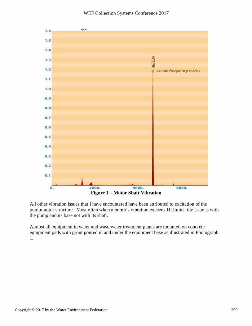
Figure 1 – Motor Shaft Vibration
All other vibration issues that I have encountered have been attributed to excitation of the
pump/motor structure. Most often when a pump’s vibration exceeds HI limits, the issue is with
the pump and its base not with its shaft.
Almost all equipment in water and wastewater treatment plants are mounted on concrete
equipment pads with grout poured in and under the equipment base as illustrated in Photograph
1.
299Copyright© 2017 by the Water Environment Federation
WEF Collection Systems Conference 2017
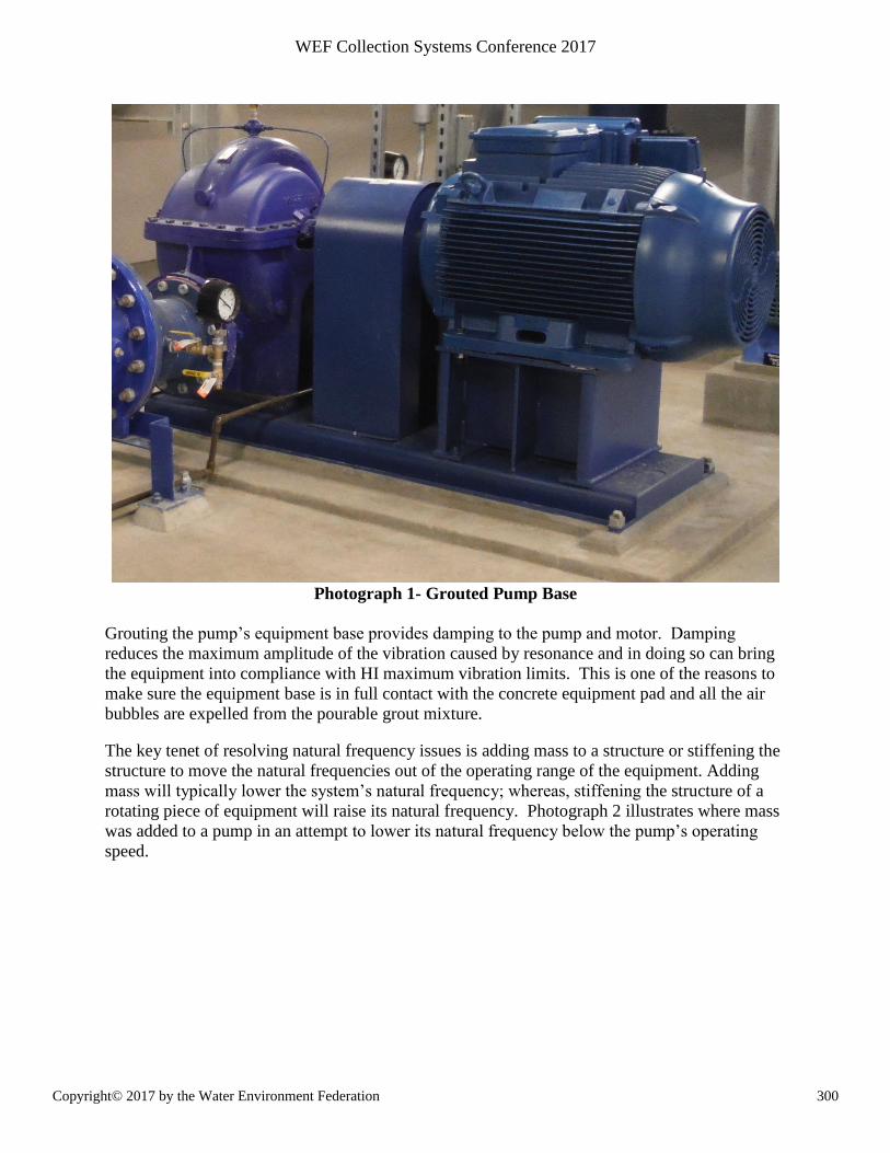
Photograph 1- Grouted Pump Base
Grouting the pump’s equipment base provides damping to the pump and motor. Damping
reduces the maximum amplitude of the vibration caused by resonance and in doing so can bring
the equipment into compliance with HI maximum vibration limits. This is one of the reasons to
make sure the equipment base is in full contact with the concrete equipment pad and all the air
bubbles are expelled from the pourable grout mixture.
The key tenet of resolving natural frequency issues is adding mass to a structure or stiffening the
structure to move the natural frequencies out of the operating range of the equipment. Adding
mass will typically lower the system’s natural frequency; whereas, stiffening the structure of a
rotating piece of equipment will raise its natural frequency. Photograph 2 illustrates where mass
was added to a pump in an attempt to lower its natural frequency below the pump’s operating
speed.
300Copyright© 2017 by the Water Environment Federation
WEF Collection Systems Conference 2017
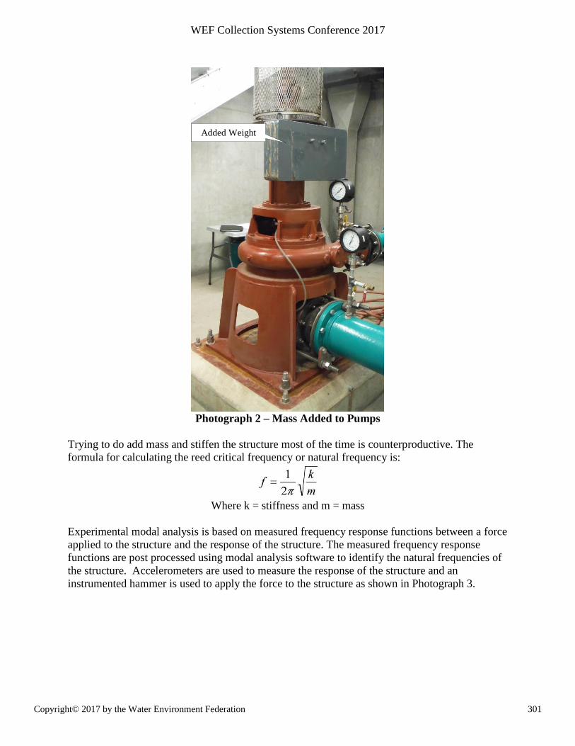
Photograph 2 – Mass Added to Pumps
Trying to do add mass and stiffen the structure most of the time is counterproductive. The
formula for calculating the reed critical frequency or natural frequency is:
Where k = stiffness and m = mass
Experimental modal analysis is based on measured frequency response functions between a force
applied to the structure and the response of the structure. The measured frequency response
functions are post processed using modal analysis software to identify the natural frequencies of
the structure. Accelerometers are used to measure the response of the structure and an
instrumented hammer is used to apply the force to the structure as shown in Photograph 3.
Added Weight
301Copyright© 2017 by the Water Environment Federation
WEF Collection Systems Conference 2017
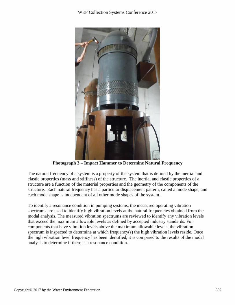
Photograph 3 – Impact Hammer to Determine Natural Frequency
The natural frequency of a system is a property of the system that is defined by the inertial and
elastic properties (mass and stiffness) of the structure. The inertial and elastic properties of a
structure are a function of the material properties and the geometry of the components of the
structure. Each natural frequency has a particular displacement pattern, called a mode shape, and
each mode shape is independent of all other mode shapes of the system.
To identify a resonance condition in pumping systems, the measured operating vibration
spectrums are used to identify high vibration levels at the natural frequencies obtained from the
modal analysis. The measured vibration spectrums are reviewed to identify any vibration levels
that exceed the maximum allowable levels as defined by accepted industry standards. For
components that have vibration levels above the maximum allowable levels, the vibration
spectrum is inspected to determine at which frequency(s) the high vibration levels reside. Once
the high vibration level frequency has been identified, it is compared to the results of the modal
analysis to determine if there is a resonance condition.
302Copyright© 2017 by the Water Environment Federation
WEF Collection Systems Conference 2017
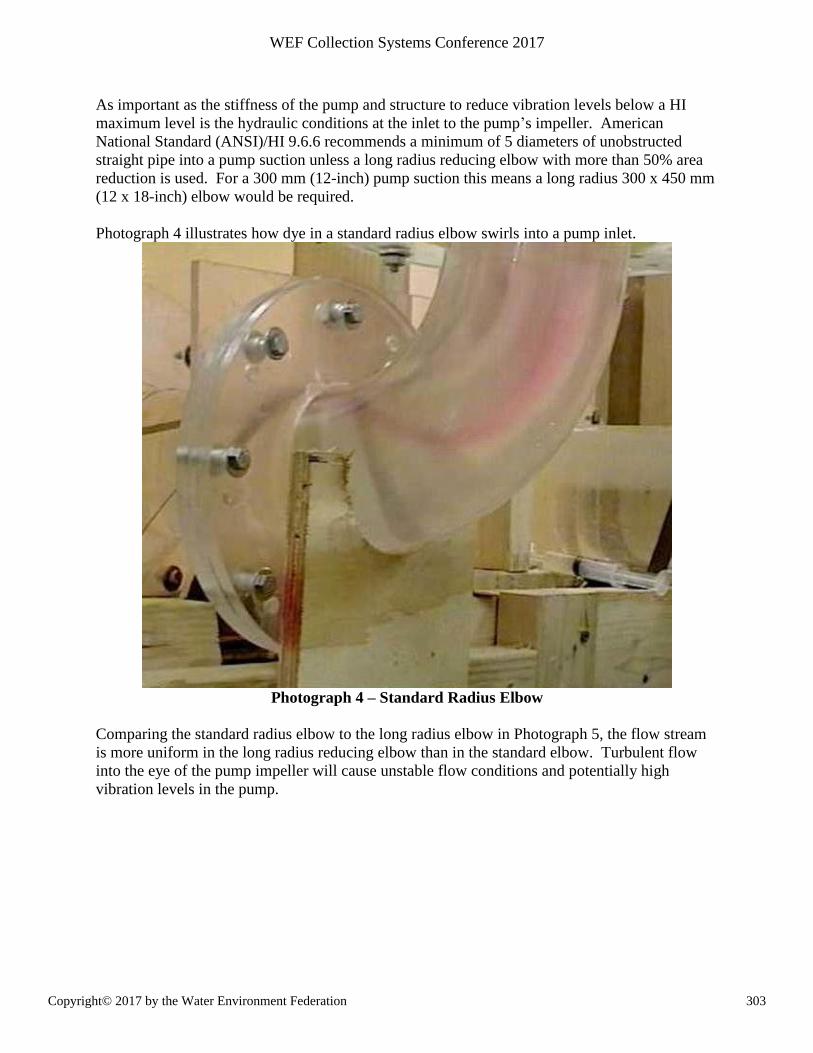
As important as the stiffness of the pump and structure to reduce vibration levels below a HI
maximum level is the hydraulic conditions at the inlet to the pump’s impeller. American
National Standard (ANSI)/HI 9.6.6 recommends a minimum of 5 diameters of unobstructed
straight pipe into a pump suction unless a long radius reducing elbow with more than 50% area
reduction is used. For a 300 mm (12-inch) pump suction this means a long radius 300 x 450 mm
(12 x 18-inch) elbow would be required.
Photograph 4 illustrates how dye in a standard radius elbow swirls into a pump inlet.
Photograph 4 – Standard Radius Elbow
Comparing the standard radius elbow to the long radius elbow in Photograph 5, the flow stream
is more uniform in the long radius reducing elbow than in the standard elbow. Turbulent flow
into the eye of the pump impeller will cause unstable flow conditions and potentially high
vibration levels in the pump.
303Copyright© 2017 by the Water Environment Federation
WEF Collection Systems Conference 2017
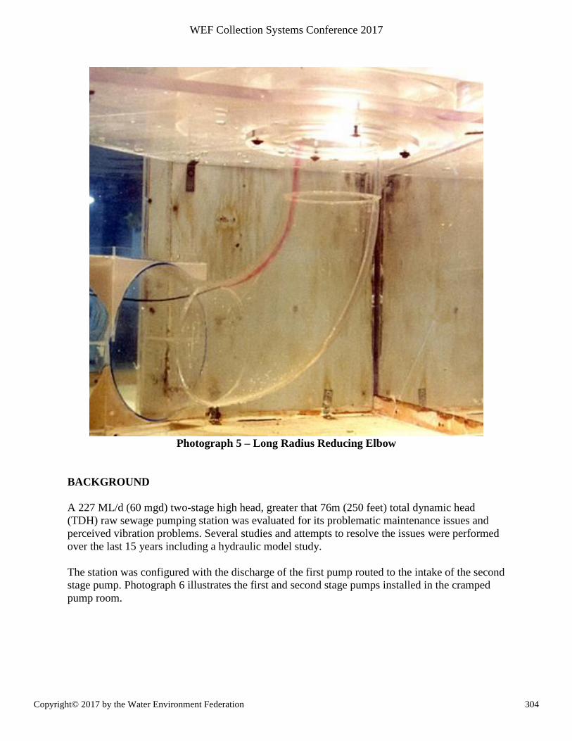
Photograph 5 – Long Radius Reducing Elbow
BACKGROUND
A 227 ML/d (60 mgd) two-stage high head, greater that 76m (250 feet) total dynamic head
(TDH) raw sewage pumping station was evaluated for its problematic maintenance issues and
perceived vibration problems. Several studies and attempts to resolve the issues were performed
over the last 15 years including a hydraulic model study.
The station was configured with the discharge of the first pump routed to the intake of the second
stage pump. Photograph 6 illustrates the first and second stage pumps installed in the cramped
pump room.
304Copyright© 2017 by the Water Environment Federation
WEF Collection Systems Conference 2017
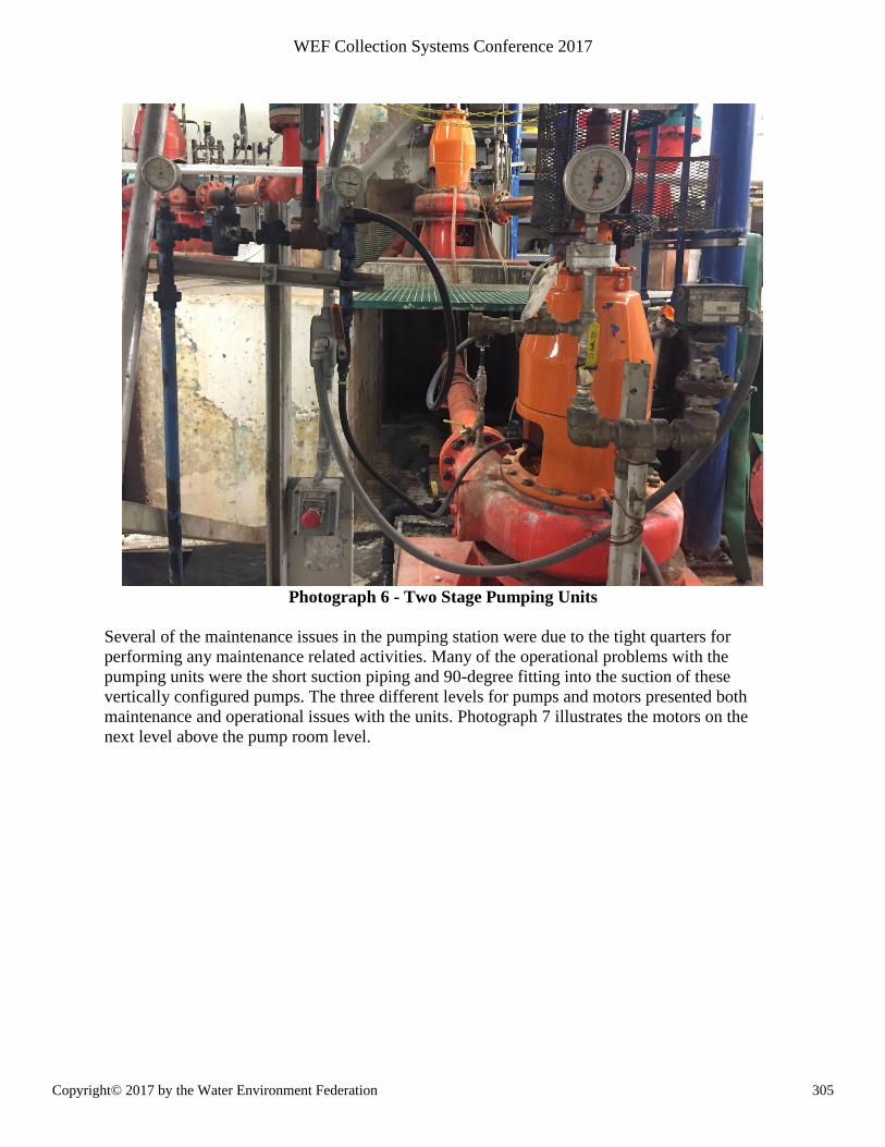
Photograph 6 - Two Stage Pumping Units
Several of the maintenance issues in the pumping station were due to the tight quarters for
performing any maintenance related activities. Many of the operational problems with the
pumping units were the short suction piping and 90-degree fitting into the suction of these
vertically configured pumps. The three different levels for pumps and motors presented both
maintenance and operational issues with the units. Photograph 7 illustrates the motors on the
next level above the pump room level.
305Copyright© 2017 by the Water Environment Federation
WEF Collection Systems Conference 2017
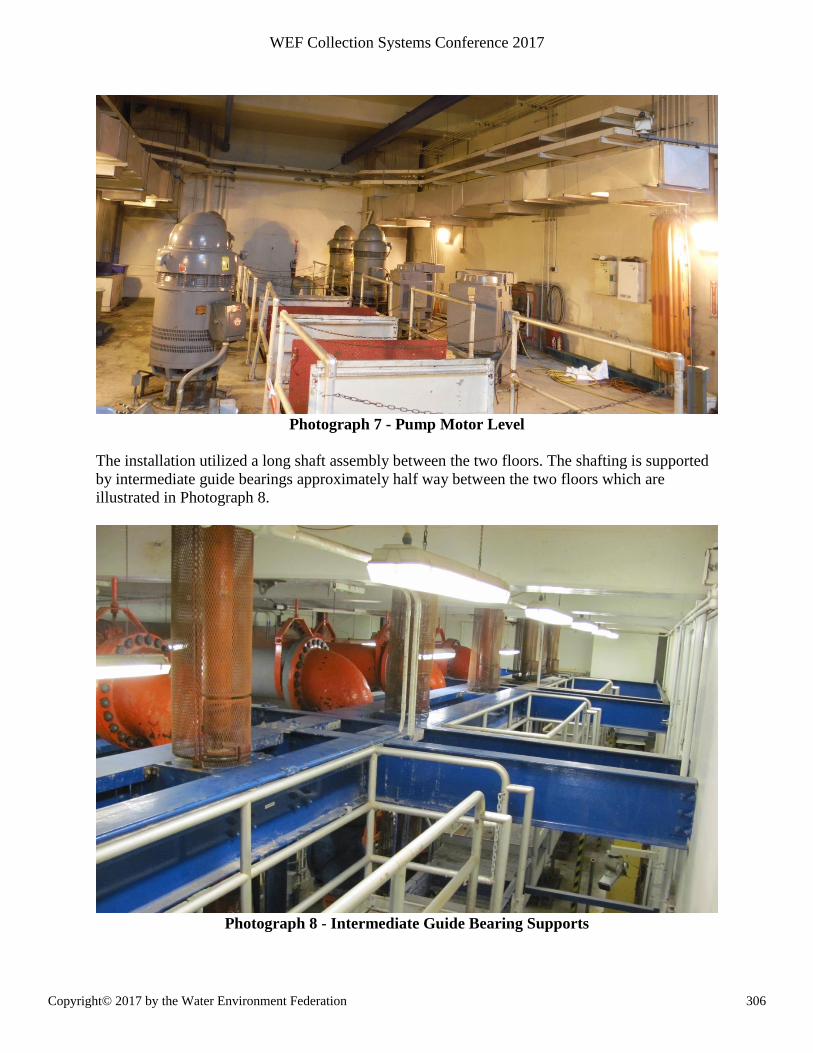
Photograph 7 - Pump Motor Level
The installation utilized a long shaft assembly between the two floors. The shafting is supported
by intermediate guide bearings approximately half way between the two floors which are
illustrated in Photograph 8.
Photograph 8 - Intermediate Guide Bearing Supports
306Copyright© 2017 by the Water Environment Federation
WEF Collection Systems Conference 2017
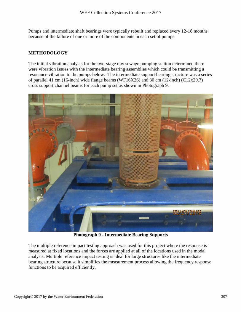
Pumps and intermediate shaft bearings were typically rebuilt and replaced every 12-18 months
because of the failure of one or more of the components in each set of pumps.
METHODOLOGY
The initial vibration analysis for the two-stage raw sewage pumping station determined there
were vibration issues with the intermediate bearing assemblies which could be transmitting a
resonance vibration to the pumps below. The intermediate support bearing structure was a series
of parallel 41 cm (16-inch) wide flange beams (WF16X26) and 30 cm (12-inch) (C12x20.7)
cross support channel beams for each pump set as shown in Photograph 9.
Photograph 9 - Intermediate Bearing Supports
The multiple reference impact testing approach was used for this project where the response is
measured at fixed locations and the forces are applied at all of the locations used in the modal
analysis. Multiple reference impact testing is ideal for large structures like the intermediate
bearing structure because it simplifies the measurement process allowing the frequency response
functions to be acquired efficiently.
307Copyright© 2017 by the Water Environment Federation
WEF Collection Systems Conference 2017
The intermediate bearing support frequency response function measurements were made using a
Dytran Instruments Model 5802A impulse hammer and 3 PCB Piezotronics Model 604B31 tri-
axial accelerometers. For each measurement point the structure was excited with the hammer
and 9 frequency response functions were measured. A total of 62 and 66 points were measured
on the stage 1 and stage 2 intermediate bearing support structures respectfully.
The measured frequency response functions were used to estimate the natural frequencies of the
intermediate bearing support structures. The OROS Modal 5.2 modal analysis software was
used to perform the modal analysis from the measured frequency response functions. For this
project, the OROS BroBand modal identification module was used which is based on the
Polyreference Least Squares Complex Frequency Algorithm.
The modal analysis identified four modes (natural frequencies) of interest in the 0-100 Hz
frequency range of the stage 1 and 2 intermediate bearing support structures. The operating
speeds of pump sets 1-4 were 1800 rpm (30 Hz) and pump sets 5-12 were 1200 rpm (20 Hz). The
modes of interest identified by modal analysis are shown in Table 1 and all are in or very close to
the pump operating ranges.
Table 1: Intermediate Bearing Support Natural Frequencies
Mode Stage 1 (Hz) Stage 2 (Hz)
1 17.08 19.38
2 19.09 21.71
3 20.97 30.60
4 29.15 33.86
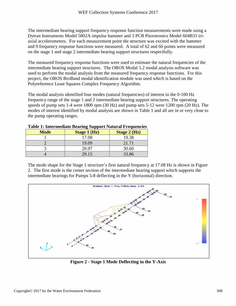
The mode shape for the Stage 1 structure’s first natural frequency at 17.08 Hz is shown in Figure
2. The first mode is the center section of the intermediate bearing support which supports the
intermediate bearings for Pumps 5-8 deflecting in the Y (horizontal) direction.
Figure 2 - Stage 1 Mode Deflecting in the Y-Axis
308Copyright© 2017 by the Water Environment Federation
WEF Collection Systems Conference 2017
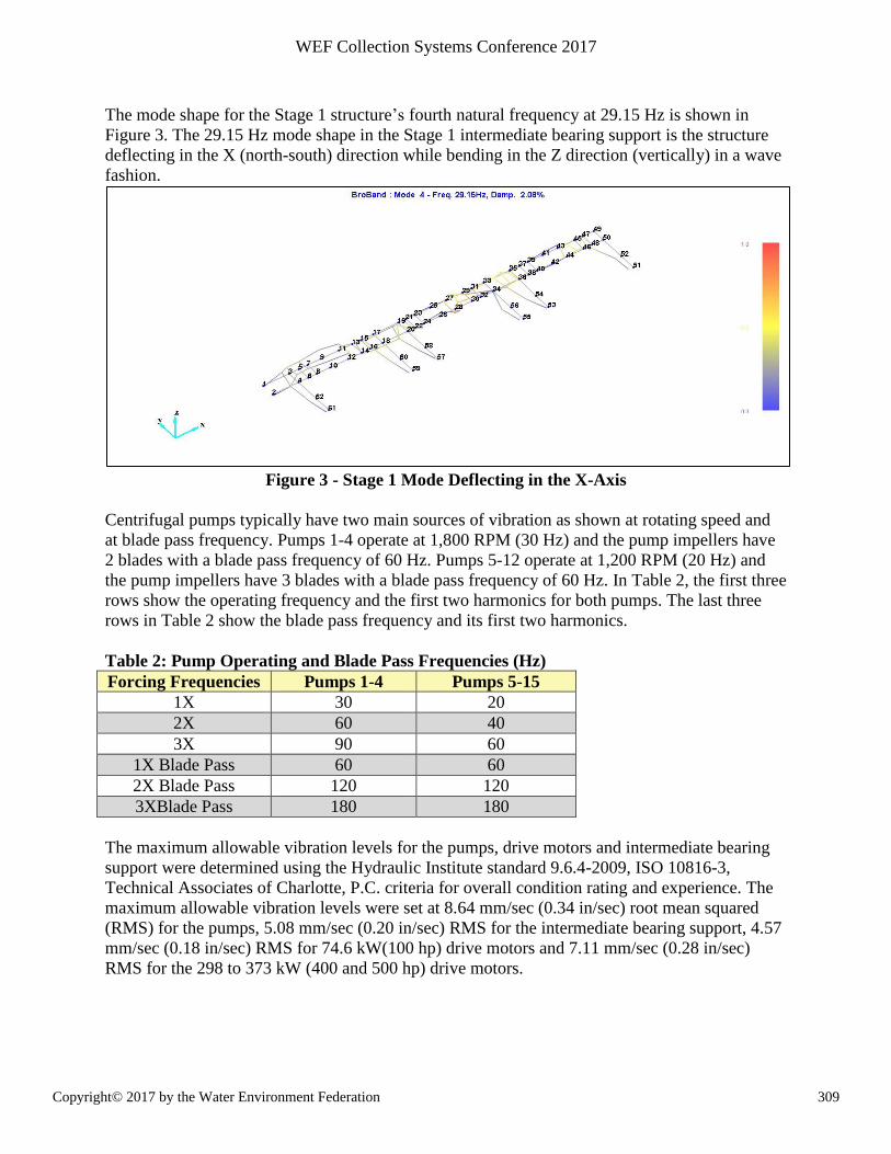
The mode shape for the Stage 1 structure’s fourth natural frequency at 29.15 Hz is shown in
Figure 3. The 29.15 Hz mode shape in the Stage 1 intermediate bearing support is the structure
deflecting in the X (north-south) direction while bending in the Z direction (vertically) in a wave
fashion.
Figure 3 - Stage 1 Mode Deflecting in the X-Axis
Centrifugal pumps typically have two main sources of vibration as shown at rotating speed and
at blade pass frequency. Pumps 1-4 operate at 1,800 RPM (30 Hz) and the pump impellers have
2 blades with a blade pass frequency of 60 Hz. Pumps 5-12 operate at 1,200 RPM (20 Hz) and
the pump impellers have 3 blades with a blade pass frequency of 60 Hz. In Table 2, the first three
rows show the operating frequency and the first two harmonics for both pumps. The last three
rows in Table 2 show the blade pass frequency and its first two harmonics.
Table 2: Pump Operating and Blade Pass Frequencies (Hz)
Forcing Frequencies Pumps 1-4 Pumps 5-15
1X 30 20
2X 60 40
3X 90 60
1X Blade Pass 60 60
2X Blade Pass 120 120
3XBlade Pass 180 180
The maximum allowable vibration levels for the pumps, drive motors and intermediate bearing
support were determined using the Hydraulic Institute standard 9.6.4-2009, ISO 10816-3,
Technical Associates of Charlotte, P.C. criteria for overall condition rating and experience. The
maximum allowable vibration levels were set at 8.64 mm/sec (0.34 in/sec) root mean squared
(RMS) for the pumps, 5.08 mm/sec (0.20 in/sec) RMS for the intermediate bearing support, 4.57
mm/sec (0.18 in/sec) RMS for 74.6 kW(100 hp) drive motors and 7.11 mm/sec (0.28 in/sec)
RMS for the 298 to 373 kW (400 and 500 hp) drive motors.
309Copyright© 2017 by the Water Environment Federation
WEF Collection Systems Conference 2017
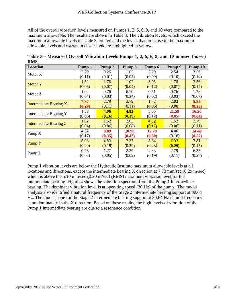
All of the overall vibration levels measured on Pumps 1, 2, 5, 6, 9, and 10 were compared to the
maximum allowable. The results are shown in Table 3. The vibration levels, which exceed the
maximum allowable levels in Table 3, are red and the levels that are close to the maximum
allowable levels and warrant a closer look are highlighted in yellow.
Table 3 - Measured Overall Vibration Levels Pumps 1, 2, 5, 6, 9, and 10 mm/sec (in/sec)
RMS
Location Pump 1 Pump 2 Pump 5 Pump 6 Pump 9 Pump 10
Motor X 2.79
(0.11)
0.25
(0.01)
1.02
(0.04)
2.29
(0.09)
2.54
(0.10)
3.56
(0.14)
Motor Y 1.52
(0.06)
1.78
(0.07)
1.02
(0.04)
3.05
(0.12)
1.78
(0.07)
3.56
(0.14)
Motor Z 1.02
(0.04)
0.76
(0.03)
6.10
(0.24)
0.51
(0.02)
0.76
(0.03)
1.78
(0.07)
Intermediate Bearing X 7.37
(0.29)
2.79
(0.11)
2.79
(0.11)
1.52
(0.06)
2.03
(0.08) 5.84
(0.23)
Intermediate Bearing Y 1.52
(0.06) 4.06
(0.16)
4.83
(0.19)
3.05
(0.12) 21.59
(0.85)
16.26
(0.64)
Intermediate Bearing Z 1.02
(0.04)
1.52
(0.06)
2.03
(0.08) 4.32
(0.17)
1.52
(0.06)
2.79
(0.11)
Pump X 4.32
(0.17) 8.89
(0.35)
10.92
(0.43)
12.70
(0.50)
4.06
(0.16) 14.48
(0.57)
Pump Y 5.08
(0.20)
4.83
(0.19)
7.37
(0.29)
5.84
(0.23) 7.37
(0.29)
3.81
(0.15)
Pump Z 0.76
(0.03)
1.27
(0.05)
2.29
(0.09)
4.83
(0.19)
2.79
(0.11)
6.35
(0.25)
Pump 1 vibration levels are below the Hydraulic Institute maximum allowable levels at all
locations and directions, except the intermediate bearing X direction at 7.73 mm/sec (0.29 in/sec)
which is above the 5.10 mm/sec (0.20 in/sec) (RMS) maximum vibration level for the
intermediate bearing. Figure 4 shows the vibration spectrum from the Pump 1 intermediate
bearing. The dominant vibration level is at operating speed (30 Hz) of the pump. The modal
analysis also identified a natural frequency of the Stage 2 intermediate bearing support at 30.64
Hz. The mode shape for the Stage 2 intermediate bearing support at 30.64 Hz natural frequency
is predominately in the X direction. Based on these results, the high levels of vibration of the
Pump 1 intermediate bearing are due to a resonance condition.
310Copyright© 2017 by the Water Environment Federation
WEF Collection Systems Conference 2017
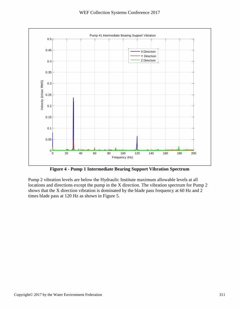
Figure 4 - Pump 1 Intermediate Bearing Support Vibration Spectrum
Pump 2 vibration levels are below the Hydraulic Institute maximum allowable levels at all
locations and directions except the pump in the X direction. The vibration spectrum for Pump 2
shows that the X direction vibration is dominated by the blade pass frequency at 60 Hz and 2
times blade pass at 120 Hz as shown in Figure 5.
0 20 40 60 80 100 120 140 160 180 2000
0.05
0.1
0.15
0.2
0.25
0.3
0.35
0.4
0.45
0.5
Frequency (Hz)
Velo
city (
in/s
ec R
MS
)
Pump #1 Intermediate Bearing Support Vibration
X Direction
Y Direction
Z Direction
311Copyright© 2017 by the Water Environment Federation
WEF Collection Systems Conference 2017
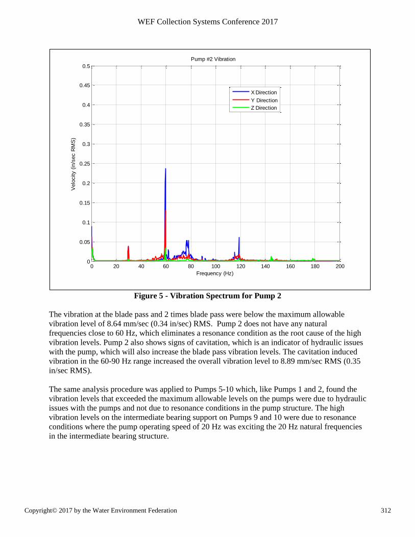
Figure 5 - Vibration Spectrum for Pump 2
The vibration at the blade pass and 2 times blade pass were below the maximum allowable
vibration level of 8.64 mm/sec (0.34 in/sec) RMS. Pump 2 does not have any natural
frequencies close to 60 Hz, which eliminates a resonance condition as the root cause of the high
vibration levels. Pump 2 also shows signs of cavitation, which is an indicator of hydraulic issues
with the pump, which will also increase the blade pass vibration levels. The cavitation induced
vibration in the 60-90 Hz range increased the overall vibration level to 8.89 mm/sec RMS (0.35
in/sec RMS).
The same analysis procedure was applied to Pumps 5-10 which, like Pumps 1 and 2, found the
vibration levels that exceeded the maximum allowable levels on the pumps were due to hydraulic
issues with the pumps and not due to resonance conditions in the pump structure. The high
vibration levels on the intermediate bearing support on Pumps 9 and 10 were due to resonance
conditions where the pump operating speed of 20 Hz was exciting the 20 Hz natural frequencies
in the intermediate bearing structure.
0 20 40 60 80 100 120 140 160 180 2000
0.05
0.1
0.15
0.2
0.25
0.3
0.35
0.4
0.45
0.5
Pump #2 Vibration
Frequency (Hz)
Velo
city (
in/s
ec R
MS
)
X Direction
Y Direction
Z Direction
312Copyright© 2017 by the Water Environment Federation
WEF Collection Systems Conference 2017
RESULTS
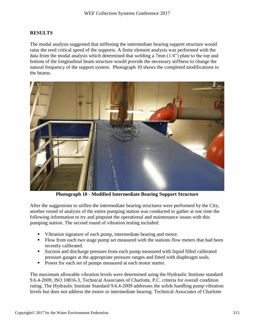
The modal analysis suggested that stiffening the intermediate bearing support structure would
raise the reed critical speed of the supports. A finite element analysis was performed with the
data from the modal analysis which determined that welding a 7mm (1/4”) plate to the top and
bottom of the longitudinal beam structure would provide the necessary stiffness to change the
natural frequency of the support system. Photograph 10 shows the completed modifications to
the beams.
Photograph 10 - Modified Intermediate Bearing Support Structure
After the suggestions to stiffen the intermediate bearing structures were performed by the City,
another round of analysis of the entire pumping station was conducted to gather at one time the
following information to try and pinpoint the operational and maintenance issues with this
pumping station. The second round of vibration testing included:
Vibration signature of each pump, intermediate bearing and motor.
Flow from each two stage pump set measured with the stations flow meters that had been
recently calibrated.
Suction and discharge pressure from each pump measured with liquid filled calibrated
pressure gauges at the appropriate pressure ranges and fitted with diaphragm seals.
Power for each set of pumps measured at each motor starter.
The maximum allowable vibration levels were determined using the Hydraulic Institute standard
9.6.4-2009, ISO 10816-3, Technical Associates of Charlotte, P.C. criteria for overall condition
rating. The Hydraulic Institute Standard 9.6.4-2009 addresses the solids handling pump vibration
levels but does not address the motor or intermediate bearing. Technical Associates of Charlotte
313Copyright© 2017 by the Water Environment Federation
WEF Collection Systems Conference 2017
criteria addresses vertical pump based on the height of the motor above grade but not a solids
handling pump specifically. Neither ISO 10816-3 nor Technical Associates of Charlotte
specifically address the intermediate bearing support maximum allowable vibration levels. The
maximum allowable vibration level for the intermediate bearing was determined from
experience.
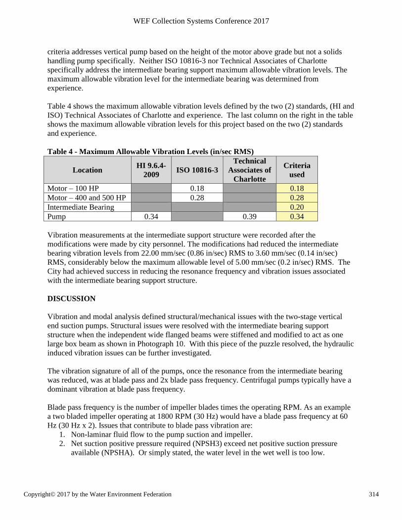
Table 4 shows the maximum allowable vibration levels defined by the two (2) standards, (HI and
ISO) Technical Associates of Charlotte and experience. The last column on the right in the table
shows the maximum allowable vibration levels for this project based on the two (2) standards
and experience.
Table 4 - Maximum Allowable Vibration Levels (in/sec RMS)
Location HI 9.6.4-
2009 ISO 10816-3
Technical
Associates of
Charlotte
Criteria
used
Motor – 100 HP 0.18 0.18
Motor – 400 and 500 HP 0.28 0.28
Intermediate Bearing 0.20
Pump 0.34 0.39 0.34
Vibration measurements at the intermediate support structure were recorded after the
modifications were made by city personnel. The modifications had reduced the intermediate
bearing vibration levels from 22.00 mm/sec (0.86 in/sec) RMS to 3.60 mm/sec (0.14 in/sec)
RMS, considerably below the maximum allowable level of 5.00 mm/sec (0.2 in/sec) RMS. The
City had achieved success in reducing the resonance frequency and vibration issues associated
with the intermediate bearing support structure.
DISCUSSION
Vibration and modal analysis defined structural/mechanical issues with the two-stage vertical
end suction pumps. Structural issues were resolved with the intermediate bearing support
structure when the independent wide flanged beams were stiffened and modified to act as one
large box beam as shown in Photograph 10. With this piece of the puzzle resolved, the hydraulic
induced vibration issues can be further investigated.
The vibration signature of all of the pumps, once the resonance from the intermediate bearing
was reduced, was at blade pass and 2x blade pass frequency. Centrifugal pumps typically have a
dominant vibration at blade pass frequency.
Blade pass frequency is the number of impeller blades times the operating RPM. As an example
a two bladed impeller operating at 1800 RPM (30 Hz) would have a blade pass frequency at 60
Hz (30 Hz x 2). Issues that contribute to blade pass vibration are:
1. Non-laminar fluid flow to the pump suction and impeller.
2. Net suction positive pressure required (NPSH3) exceed net positive suction pressure
available (NPSHA). Or simply stated, the water level in the wet well is too low.
314Copyright© 2017 by the Water Environment Federation
WEF Collection Systems Conference 2017
3. Pump operating outside of the pump’s preferred operating range (POR) and/or to the far
right of the acceptable operating range (AOR).
Further detailed investigation and analysis of the data collected will be required to pinpoint the
root cause of the continued hydraulic vibration issues with the raw sewage two-stage vertical end
suction centrifugal pumps.
CONCLUSION
Modal and vibration spectrum analysis, while not the ultimate resource for diagnosing and
resolving mechanical failures, are powerful tools to assist operation and maintenance personnel
in determining some of the root causes of equipment failure. As was the case in the investigation
of the two-stage vertical end suction pumps, one issue was eliminated; however, several other
potential problems were uncovered.
Vibration monitoring is a great evaluation tool that can be used to diagnose issues and problems.
It can and should be a tool for acceptance of installed pumps to confirm they meet the minimum
American National Standards Institute/Hydraulic Institute Standards.
ACKNOWLEDGEMENTS
The authors gratefully acknowledge the staff at the wastewater pumping stations for their
patience while all of the issues were investigated and satisfactorily resolved. I also wish to thank
the construction personnel that persevered during the issues with the suppliers and factory
personnel as well as the hydraulic modeling laboratory for their continued help in evaluating
pumping station hydraulics. Balancing Services Company and AVS Engineering, LLC are
thanked for their continued assistance in diagnosing vibration issues with rotating equipment
across the country.
REFERENCES
Hydraulic Institute (2009) Rotodynamic Pumps for Vibration Measurements and Allowable
Values; ANSI/HI 9.6.4; Parsippany, New Jersey.
Hydraulic Institute (2009) Rotodynamic Pumps for Pump Piping; ANSI/HI 9.6.6; Parsippany,
New Jersey.
Technical Associates of Charlotte, P.C. Vibration Criteria; Charlotte, North Carolina.
International Organization for Standardization, 10816-3:2009 – Mechanical Vibration, Geneva,
Switzerland
315Copyright© 2017 by the Water Environment Federation
WEF Collection Systems Conference 2017