mobility management architecture and modeling for label
TRANSCRIPT

Mobility Management Architecture and Modeling
for
Label Switched Networks
(Mobility Label Based Network)
A Thesis
Submitted to the Faculty
of
Drexel University
by
Oleg Berzin
in partial fulfillment of the
requirements for the degree
of
Doctor of Philosophy
March 2010

© Copyright 2009 Oleg Berzin. All Right Reserved.

ii
Dedications
In memory of my father Leonid Berzin (1941 - 2001)
An inventor and an artist

iii
Acknowledgements
I would like to express my deepest gratitude to Dr. Stuart Elby for his inspiration, insight
and support, to my advisor Dr. Afshin Daryoush for his efforts and direction, Dr.
Jaudalice de Oliveira for her advice and encouragement, Dr. Steven Weber for his time
and help, Dr. Harish Sethu for his constructive criticism and finally to my dear and
loving Tatyana for being there for me throughout this endeavor.
OLEG BERZIN
Drexel University
Philadelphia, PA
March 2010

iv
Table of Contents
List of Tables ...................................................................................................................... x
List of Figures .................................................................................................................... xi
CHAPTER 1. INTRODUCTION ....................................................................................... 1
1.1 Overview of mobility management as a network problem................................. 1
1.1.1 Network layer mobility management problem space ................................. 1
1.1.2. Internet Protocol Mobility........................................................................... 4
1.2. Design criteria for a network layer mobility management solution ................... 7
1.3. Departure from Mobile IP................................................................................... 8
1.4. Summary of contributions................................................................................. 11
1.4.1. Benefits of Hierarchical Mobility Label Based Network ......................... 11
CHAPTER 2. RELEATED WORK ................................................................................. 13
2.1. Mobile IP Macro-Mobility................................................................................ 13
2.1.1. Mobile IPv4 (MIPv4)................................................................................ 13
2.1.2. Mobile IPv4 with Route Optimization (ROMIPv4) ................................. 14
2.1.3. Mobile IPv4 Network Mobility (NEMOv4) ............................................. 15
2.1.4. Mobile IPv6 (MIPv6)................................................................................ 15
2.1.5. Mobile IPv6 Network Mobility (NEMOv6) ............................................. 16
2.1.6. Network Based Mobile IP (PMIP)............................................................ 17
2.2. Mobile IP Micro-Mobility ................................................................................ 18
2.2.1. Mobile IPv4 Regional Registration (RRMIPv4) ...................................... 18
2.2.2. Hierarchical Mobile IPv6 (HMIPv6) ........................................................ 19
2.3. MPLS Micro-Mobility ...................................................................................... 20

v
2.3.1. LEMA MPLS-based Micro-Mobility (LMM-MPLS) .............................. 21
2.3.2. Micro Mobile MPLS (MM-MPLS) .......................................................... 23
2.3.3. Micro-cell Mobile MPLS (MCM-MPLS) ................................................ 25
2.3.4. Micro-Mobile MPLS Radio Access Network (RAN-MM-MPLS) .......... 25
2.3.5. Micro-mobility enabled MPLS (MM-MPLS-MIPv6) .............................. 26
2.4. Summary and Comparison................................................................................ 27
CHAPTER 3. MOBILITY LABEL BASED NETWORK............................................... 29
3.1. Multi-Protocol Label Switching ....................................................................... 29
3.2. Multi-Protocol Border Gateway Protocol......................................................... 32
3.3. Mobility Label Based Network......................................................................... 34
3.3.1. MPLS-aware Mobility Control Plane ....................................................... 34
3.3.2. Basic Architecture of MLBN.................................................................... 36
3.3.2.1. Radio Network Attachment Options ................................................................38
3.3.2.2. Control Plane Description................................................................................40
3.3.2.3. Forwarding Plane Description .........................................................................43
3.4. Chapter Summary ............................................................................................. 44
CHAPTER 4. HIERARCHICAL MOBILITY LABEL BASED NETWORK................ 46
4.1. Network Scalability Considerations ................................................................. 46
4.2. Hierarchical Mobility Label Based Network.................................................... 52
4.2.1. Definition of Entities................................................................................. 52
4.2.2. Description of Architecture....................................................................... 56
4.3. Operation of H-MLBN ..................................................................................... 63
4.3.1. Start-UP Procedures.................................................................................. 63
4.3.2. Hand-off Procedures ................................................................................. 68

vi
4.3.2.1. MSF-Local Hand-off.............................................................................................68
4.3.2.2. Inter-MSF Intra-Area Hand-off.........................................................................70
4.3.2.3. Inter-MSF Inter-Area Hand-off.........................................................................74
4.3.3. Regional Address Pools (RAP)................................................................. 78
4.3.3.1. Mobility Pool Bindings and their Distribution ...................................................81
4.3.3.2. Ingress LER Address Lookup..........................................................................85
4.3.3.3. Start-Up Sequence with Regional Address Pools ...........................................87
4.3.4. Hand-off Processing with Regional Address Pools .................................. 88
4.3.4.1. Inter-MSF Intra-Area RAP Hand-off ................................................................88
4.3.4.2. Inter-MSF Inter-Area RAP Hand-off ................................................................90
4.3.5. Discussion................................................................................................. 91
4.3.5.1. Need for AMRR ...............................................................................................91
4.3.5.2. Survivability and Load Distribution ..................................................................93
4.3.5.3. Scope of Mobility Labels..................................................................................95
4.3.5.4. Scope of Mobility LSPs....................................................................................97
4.3.5.5. Mobile Node Multi-Homing and Traffic Continuity ...........................................98
4.3.5.6. Role of Area-ID ..............................................................................................101
4.3.5.7. Mobility Binding Lifetime and Transient Conditions.......................................103
4.3.6. Applications for Mobility Labels............................................................ 106
4.3.6.1. RAN Differentiation........................................................................................106
4.3.6.2. Normalization of IP Address Lookup Time ....................................................107
4.3.6.3. Network Virtualization....................................................................................108
4.3.6.4. Inter-Carrier Roaming....................................................................................108
4.4. Chapter Summary ........................................................................................... 110
CHAPTER 5. SYSTEM MODEL .................................................................................. 113
5.1. Movement Model............................................................................................ 113
5.1.1. Mobility Region Structure ...................................................................... 113

vii
5.1.2. Movement in the Mobility Region.......................................................... 115
5.1.2.1. Dwelling Time in a RAN Cell .........................................................................115
5.1.2.2. Inter-Cell Movements.....................................................................................116
5.1.2.3. Random Walk in a Mobility Region................................................................120
5.1.3. Mobility Area Structure .......................................................................... 124
5.1.4. Movement in the Mobility Area ............................................................. 126
5.1.5. Movement during Active Life ................................................................ 127
5.1.6. Movement between Mobility Areas........................................................ 131
5.2. Traffic Model .................................................................................................. 133
5.2.1. Forwarding Plane Traffic Model ............................................................ 133
5.3. Control Plane Traffic Model........................................................................... 138
5.4. Control Plane Processing Model..................................................................... 145
5.5. Chapter Summary ........................................................................................... 151
CHAPTER 6. PERFORMANCE AND COMPARATIVE ANALYSIS ....................... 152
6.1. System Performance Metrics .......................................................................... 152
6.1.1. Link Count .............................................................................................. 152
6.1.1.1. H-MLBN .........................................................................................................152
6.1.1.2. Mobile IP........................................................................................................153
6.1.1.3. User and Network-facing Penalties for Triangular Routing ...........................155
6.1.2. Hand-off Time ........................................................................................ 157
6.1.2.1. H-MLBN .........................................................................................................157
6.1.2.2. Mobile IP........................................................................................................161
6.1.3. Control Plane Costs................................................................................. 165
6.1.3.1. H-MLBN .........................................................................................................165
6.1.3.2. Mobile IP........................................................................................................165

viii
6.2. Numerical and Simulation Results.................................................................. 168
6.3. Chapter Summary ........................................................................................... 185
CHAPTER 7. CONCLUSION........................................................................................ 187
7.1. Design Principals ............................................................................................ 187
7.2. Future Work .................................................................................................... 189
List of References ........................................................................................................... 192
APPENDIX A. PROTOCOL ELEMENTS AND MESSAGE FORMATS ............ 195
A.1. Mobility Support Function.............................................................................. 195
A.1.1. Mobile Node Discovery, Registration and Status....................................... 195
A.1.1.1. Discovery Process - IPv4 .................................................................................195
A.1.1.2. MSF Discovery by Mobile Hosts - IPv4 ............................................................197
A.1.1.3. MSF Discovery by Mobile Routers - IPv4.........................................................198
A.1.1.4. MSF Advertisement - IPv4................................................................................199
A.1.2. Discovery Process - IPv6 ............................................................................ 200
A.1.3. Registration and Status - IPv4..................................................................... 200
A.1.3.1. Mobile Host Registration - IPv4........................................................................200
A.1.3.2. Mobile Router Registration - IPv4 ....................................................................203
A.1.4. Registration and Status - IPv6..................................................................... 205
A.2. Integration with MP-BGP .................................................................................. 205
A.2.1. Mobility Address Family ............................................................................ 206
A.2.2. Mobility Bindings ....................................................................................... 207
A.3. Network Update Modes and Types.................................................................... 211
A.3.1. Unsolicited Downstream Push Mode.......................................................... 211
A.3.2. Selective Downstream Push Mode ............................................................. 211

ix
A.3.3. Hierarchical On-Demand Distribution Mode ............................................. 211
A.3.3.1. On-Demand Requests for Mobility Binding Information ...................................212
A.3.4. Network Update Types ............................................................................... 215
A.3.4.1. Internal Update Type ........................................................................................215
A.3.4.2. External Update Type.......................................................................................215
APPENDIX B. LIST OF ACRONYMS .................................................................. 216
VITA............................................................................................................................... 219

x
List of Tables
Table 2.1. Summary of the Existing Solutions and Comparison with H-MLBN............. 28
Table 6.1. Hand-off Type Mapping between H-MLBN and MIP .................................. 163
Table 6.2. Event Rate Mapping between H-MLBN and MIP ........................................ 165
Table 6.3. Numerical Parameters.................................................................................... 168

xi
List of Figures
Figure 1.1. Illustration of Internet Protocol Mobility. ........................................................ 6
Figure 2.1. Illustration of Hierarchical Mobile IPv6. ....................................................... 19
Figure 2.2. Illustration of LEMA MPLS-based Micro-Mobility...................................... 23
Figure 2.3. Illustration of Micro Mobile MPLS ............................................................... 24
Figure 3.1. Overlay MPLS Service with MP-BGP........................................................... 34
Figure 3.2. Mobility Support Function ............................................................................. 36
Figure 3.3. High Level Architecture of MLBN. ............................................................... 38
Figure 3.4. Illustration of the Direct RAN Attachment Option. ....................................... 39
Figure 3.5. Illustration of the Indirect RAN Attachment Option...................................... 40
Figure 3.6. Illustration of the Basic Mobility Binding Distribution in MLBN................. 42
Figure 4.1. Separation of Control and Forwarding Planes and Control Plane Hierarchy. 51
Figure 4.2. Hierarchical Mobility Label Based Network ................................................. 57
Figure 4.3. H-MLBN Network Update Types .................................................................. 59
Figure 4.4. Hierarchical Mobility Forwarding Plane and Segmented LSPs..................... 62
Figure 4.5. Sample ALER Forwarding Information Base Structure. ............................... 64
Figure 4.6. Illustration of H-MLBN Start-Up Sequence .................................................. 67
Figure 4.7. Timing diagram of H-MLBN Start-Up Sequence .......................................... 68
Figure 4.8. MSF-Local Hand-off ...................................................................................... 70
Figure 4.9. Inter-MSF Intra-Area Hand-off...................................................................... 73
Figure 4.10. Timing diagram of Inter-MSF Intra-Area Hand-off..................................... 73
Figure 4.11. Inter-MSF Inter-Area Hand-off.................................................................... 77
Figure 4.12. Timing diagram of Inter-MSF Inter-Area Hand-off..................................... 78

xii
Figure 4.13. Regional Address Pool (RAP) and Mobility Pool Label Range (MPLR).... 80
Figure 4.14. ALER Regional Address Pool FIB Entry..................................................... 83
Figure 4.15. Mobility Pool Binding Distribution Process ................................................ 84
Figure 4.16. State Diagram of Interactions between MN, LER, AMRR and ALER........ 92
Figure 4.17. High Availability Configuration for Mobility Area ..................................... 94
Figure 4.18. Area ID Processing Logic. ......................................................................... 102
Figure 4.19. Mobility Binding Withdrawal Process. ...................................................... 106
Figure 4.20. Inter-Carrier Roaming with H-MLBN ....................................................... 109
Figure 5.1. Cell Radius (a), Movement Distribution (b)................................................. 114
Figure 5.2. Mobility Region L = 3; N = 37L = 3; N = 37................................................................. 114
Figure 5.3. An Illustration of the H2RWP Process......................................................... 118
Figure 5.4. A Random Waypoint Process....................................................................... 118
Figure 5.5 Connected Graph Representing the Mobility Region. .................................. 121
Figure 5.6. Approximating Square for a Mobility Region.............................................. 125
Figure 5.7. Mobility Area (a), Connected Graph for Mobility Area (b)......................... 125
Figure 5.8. Mobility Area Crossing Diagram. ................................................................ 128
Figure 5.9. Four Mobility Areas (a) and Transition Probability Matrix (b). .................. 132
Figure 5.10. Sample H-MLBN with D = 5D = 5, a) Network View, b) Graph View. ........... 134
Figure 5.11. State Transition Diagram for the CTMC Representing Forwarding Plane.136
Figure 5.12. Relationship Between Boundary Crossings: Cell, Region and Area. ........ 140
Figure 5.12. Network Update Event Rate Types. ........................................................... 143
Figure 5.14. Control Plane Network Update Messaging and Cost Mapping.................. 147
Figure 6.1. Communication Path with Mobile IP: a) Single HA, b) Two HAs.............. 153

xiii
Figure 6.2. MN Heartbeat and Heartbeat Timeout (a), Hand-off Detection (b). ............ 158
Figure 6.3. Relationship between the LMR and the Estimated Speed of MN................ 171
Figure 6.4. Average Number of Boundary Crossings per Active Life Time.................. 172
Figure 6.5a. Distributions of RAN Cell Boundary Crossing Probabilities..................... 173
Figure 6.5b. Distributions of Mobility Region Boundary Crossing Probabilities. ......... 174
Figure 6.5c. Distributions of Mobility Area Boundary Crossing Probabilities. ............. 175
Figure 6.6. Average Link Count and Average Excess Link Utilization. ........................ 176
Figure 6.7. Average Aggregate Excess Network Utilization.......................................... 177
Figure 6.8. Average Increase in Delay and Packet Loss Probability.............................. 178
Figure 6.9. Hand-off Intensity ½h½h vs. Life-to-Mobility Ratio ½c½c. ................................... 179
Figure 6.10. Update Rates as a Function of LMR. ......................................................... 180
Figure 6.11. Combined Control Plane Message Delivery Cost. ..................................... 182
Figure 6.12. Combined Control Plane Message Processing Cost................................... 183
Figure 6.13. Combined Composite Control Plane Network Update Cost vs. LMR....... 184
Figure A.1. ICMP Router Solicitation with MSF Discovery Extension ........................ 195
Figure A.2. ICMP Router Advertisement with MSF Advertisement Extension ............ 196
Figure A.3. Mobile Host MSF Discovery Extension for IPv4 ....................................... 197
Figure A.4. Mobile Router MSF Discovery Extension ................................................ 198
Figure A.5. MSF Advertisement Extension.................................................................... 199
Figure A.6. Full Registration Request ............................................................................ 201
Figure A.7. Full Registration Reply................................................................................ 202
Figure A.8. Mobile Router Explicit Prefix Registration Message.................................. 204
Figure A.9. MP_REACH_NLRI with Mobility Binding ............................................... 206

xiv
Figure A.10. MP_UNREACH_NLRI with Mobility Binding........................................ 207
Figure A.11. NLRI Encoding for Mobility Bindings ..................................................... 207
Figure A.12. NLRI Encoding for the Host Mobility Binding......................................... 208
Figure A.13. NLRI Encoding for the Router Mobility Binding ..................................... 209
Figure A.14. NLRI Encoding for On-Demand Mobility Binding Request .................... 213
Figure A.15. NLRI Encoding for On-Demand LRL Reply ............................................ 214

xv
Abstract
Mobility Management Architecture and Modeling for Label Switched Networks
(Mobility Label Based Network) Oleg Berzin
Afshin S. Daryoush, PhD.
With the proliferation of IP based mobile applications network layer mobility
management is expected to play an increasingly significant role in the architectures of the
mobile networks. The mobile network evolution offers higher data rates and lower
latencies that target mobile-to-mobile traffic patterns and applications that are all based
on IP. However, the underlying network layer mobility management schemes employed
in the 3G and 4G architectures are not optimized for mobile-to-mobile traffic patterns and
result in the user- as well as the network-facing performance penalties that may be
considered as inhibiting factors in the network evolution.
We present a Mobility Label Based Network (MLBN) - a new approach to the
network layer mobility management that relies on Multi-Protocol Label Switching
(MPLS) and provides native integration between the MPLS-aware control and the
MPLS-based forwarding planes. MLBN is a scalable, survivable hierarchical mobility
management system capable of providing macro- and micro-mobility for IPv4 or IPv6
mobile hosts or routers without the use of Mobile IP while guaranteeing optimal traffic
routing between the communicating mobile devices. MLBN uses MPLS to decouple the
IP address assigned to a mobile node or a prefix served by a mobile router from the
logical topology of the IP network thus resolving a topological conflict associated with
the move of a mobile node from a home to a foreign IP network.

xvi
When a user connects to the MLBN the mobile device is associated with a
Mobility Label while maintaining the original IP address. The Mobility Label is then
bound to the device’s IP address at the edge of the MLBN and this binding is advertised
using the MPLS-aware control plane protocol into the label switched network. We show
that it is possible to effectively update the network following the mobile node movements
and perform optimal packet routing based on the modifiable sequence of the Label
Switched Paths.


1
CHAPTER 1. INTRODUCTION This chapter provides an overview of the network layer mobility management problem
space and describes the major design criteria for a mobility management solution. Section
1.1 introduces the network layer mobility management, Section 1.2 outlines the design
criteria for a mobility management solution, Section 1.3 describes the proposed solution
and Section 1.4 summarizes the contributions of the thesis.
1.1 Overview of mobility management as a network problem To support mobility the network control plane is required to detect changes in the mobile
node’s location and distribute the new location information throughout the network thus
enabling the forwarding plane to deliver traffic to a mobile node. Control plane refers to
the network signaling and the associated protocols and resources (such as route
processors). Forwarding plane refers to the network traffic forwarding protocols and
resources (such as switching fabrics). The network responsiveness to the mobile node
movements can be generally thought of as the time elapsed between the moment the
node’s location in the network has changed and the moment the reception of packets in
the new location has resumed.
1.1.1 Network layer mobility management problem space In the context of IP networks the location of a device within the network infrastructure is
defined by a network layer address, an IPv4 or IPv6 address, assigned to or acquired by
the device. In a conventional IP network the network layer topology is static and is
essentially comprised of a collection of IP sub-nets overlaid on the physical topology.
Each sub-net is a contiguous range of IP addresses identified by the sub-net address and

2
the sub-net mask. The sub-net address is used together with the sub-net mask to define a
range of usable IP addresses that may be allocated to the devices that reside within the
sub-net.
Normal IP network routing relies on the sub-network or network level
reachability information (as opposed to the host level) based on the pre-determined
distribution of sub-nets. A topological conflict is created when a mobile node enters a
foreign sub-net and keeps it’s original home network address. The network does not
know that the node’s location has changed and keeps forwarding the traffic to the old
location based on the original address and the sub-net to which it topologically belongs.
Therefore a problem statement for the network layer mobility management may
be formulated in the following manner: “How to update the network on the new logical
location of the mobile node and deliver the traffic to it following the optimal path and
with minimal disruption in service?” The optimal network path is interpreted as the path
that allows delivery of packets to the new mobile node location following the best (often
the shortest) path between the mobile node and the correspondent node. We note that the
problem statement refers to two major components of the network: the control plane that
is responsible for the network update processes and the forwarding plane that is
responsible for the traffic delivery process.
The function of the mobility control plane is to acquire and distribute the logical
location information for the mobile nodes when they move into foreign sub-nets. In the
context of a network layer mobility logical location information is captured in the
network addressing parameters such as the link layer address of the mobile node, the
network layer address of the mobile node and the foreign subnet address to which the

3
mobile node has transitioned. The acquisition process may be a registration procedure
initiated by the mobile node with the edge node of the network in the foreign sub-net
(with respect to the mobile node’s home sub-net). Following the registration process the
network edge node in the foreign sub-net must assign new identifying information for the
visiting mobile node while allowing the mobile to keep the original home address so that
the higher layer application protocols would not detect the change in the application
socket. The new identifying information provides a mapping between the original
network layer address of the mobile and the foreign sub-net the mobile is visiting. The
mobility control plane is then responsible for updating the rest of the network with this
mapping (referred to as a binding) in such a manner that the network forwarding plane is
capable of delivering traffic addressed to the original home address of the visiting mobile
node now located in the foreign sub-net.
The outcome of the processing performed by the mobility control plane dictates
how the forwarding plane delivers the traffic. We distinguish two main alternatives for
the traffic delivery between the communicating mobile nodes by the forwarding plane:
optimal and sub-optimal delivery. Optimal delivery follows the best path between the
source (often referred to as a correspondent node) and the destination mobile node (note
that the correspondent node may also be a mobile node). The best path is determined by
the network routing metrics. Sub-optimal delivery requires that the traffic between the
source and the destination be processed by additional network nodes that are not part of
the optimal path as a result of the control plane mapping operation.

4
The service disruption is captured by the time interval between the moment the
mobile node’s location in the network has changed and the moment the reception of
packets in the foreign sub-net has resumed.
1.1.2. Internet Protocol Mobility Network layer mobility management has been an active research area for a significant
amount of time. The first basic solution enabling mobility in the Internet Protocol (IP)
environment was proposed by C. Perkins and became an Internet Engineering Task Force
(IETF) standard published in the Request For Comment (RFC) 3344 [4] known as
Mobile IP. It provides a basic capability for the mobile nodes using IP as the network
layer protocol to maintain IP addressing and application continuity (via maintaining the
application socket numbering) while transitioning between IP sub-nets that are different
from the mobile’s home sub-net. The operation of Mobile IP is briefly described here to
illustrate the problem space concepts outlined in the previous section.
Due to its complete reliance on the logical network topology determined by the
distribution of the IP sub-nets Mobile IP solves the mobility problem by using the
following two major techniques: mobile node registration and traffic tunneling. The main
entities in Mobile IP are the Mobile Node (MN) itself, the Correspondent Node (CN) –
the host that is communicating with the MN, the Home Agent (HA) – this is the router
that owns the original home sub-net to which the MN is assigned, the Foreign Agent (FA)
– this is the router that owns the sub-net to which the MN has moved (the foreign sub-
net), and finally the Care-of-Address (CoA) – the IP address that belongs to the FA and
that is used to represent the MN while it is located in the foreign sub-net.

5
The basic operation of Mobile IP starts with the MN entering the foreign sub-net
and discovering the FA node by listening to router advertisements. Once the MN
determines that it is in the foreign sub-net it initiates the registration process with the FA.
The outcome of this process is that the FA records the link layer addressing information
for the MN and the associated IP address. FA then associates a CoA with the MN.
Following this successful registration the MN also registers itself to the HA by letting the
HA know its real IP address (Home Address) as well as the CoA address of the FA. After
these registration procedures are complete, the packets destined to the MN by any CN in
the IP network are first conventionally forwarded to the MN’s home sub-net where they
are handled by the HA. The HA knowing the new location of the MN by means of
verifying the active registration status and the corresponding CoA forwards the traffic
from the CN to the MN by way of FA using the IP tunneling such as IP-IP or GRE [6]
with the tunnel source being one of its own (HA) IP addresses and the tunnel destination
being the CoA address. When the traffic is tunneled to the FA it is recovered from the
tunnel encapsulation and then forwarded to the MN by using the corresponding delivery
network. In the reverse direction the traffic from the MN node does not need to be
encapsulated and tunneled. Instead the packets may be sent directly to the IP address of
the CN. The registration status of the MN with the FA and the HA is periodically
validated by using the registration messaging. When the MN changes its location the
basic process repeats again. The operation of Mobile IP is illustrated in Figure 1.1.
Note that Mobile IP incorporates both the control plane and the forwarding plane
elements. At the control plane the acquisition of the logical location information for the
MN is achieved through the registration process. The functional entity that is used to

6
represent the new logical location of the MN in the network is another IP address - the
CoA – that is topologically correct in the foreign sub-net. The network update process is
initiated by the MN itself and consist of sending a Mobile IP binding (a mapping between
the MN’s home address and the FA’s CoA) from FA to HA. At the forwarding plane,
conventional IP destination address based forwarding is used, where all traffic for the
MN’s home address is routed to the Home Agent and the HA uses tunneling to
encapsulate the original packet and send it to the CoA of the FA.
The control plane operation is simple and involves only two network nodes per
MN (FA and HA). However the traffic delivery by the forwarding plane is sub-optimal as
all traffic must visit the HA on its way to MN while there may be a more direct path
between the CN and MN.
Figure 1.1. Illustration of Internet Protocol Mobility.

7
1.2. Design criteria for a network layer mobility management solution
Design of the network layer mobility management scheme involves both the network
protocol and the network architecture considerations that together enable to address the
question posed by the problem statement. Since the mobility control plane operation
plays a critical role in the solution the network protocol chosen for the control plane
function and the underlying network architecture also become critical. At the same time
due to established IP network architectures and protocols the network layer mobility
management solution must be able to re-use to a great degree the existing network
realities in order to be considered for a practical adoption by the internetworking
community. We specify the following design criteria for the solution:
Integrated control and forwarding planes - the network update process by the
control plane must result in the optimal traffic delivery by the forwarding plane.
Robust and flexible control plane protocol framework – mobility control plane
protocol and the associated functions must be placed at the intelligent network edges and
allow to avoid the need to involve all nodes in the network (including the core nodes) in
the control plane update process. The control plane protocol must be able to support IPv4
or IPv6 mobile hosts and mobile routers and allow for seamless introduction of new
control plane features.
Evolutionary architecture and implementation approach - mobility management
scheme should be based as much as possible on the existing network architectures and
protocol framework.

8
Efficient network responsiveness - the impact on the mobile application due to the
service disruption caused by the mobile node’s movements and the associated network
update and delivery processes should be reasonably minimal.
Acceptable network scalability and performance - the new requirements for
mobility management functions should not result in decreased network scalability,
reliability and robustness.
1.3. Departure from Mobile IP
Mobile IP solves the network layer mobility management problem by essentially
representing one IP address by another (the MN’s home address is represented by the
FA’s Care-of-Address) and anchoring the MN’s virtual location always at the Home
Agent (where the MN’s home address belongs topologically). Due to this basic Mobile IP
always results in sub-optimal traffic delivery at the network forwarding plane.
Thus it would be highly desirable for the mobility support architecture to be able
to decouple the network layer (IP) addressing and the associated logical network
topology from the ability of the network to optimally deliver packets to the mobile node
regardless of the IP address assigned to the mobile node. Therefore a new method is
required to identify the logical location of the MN in the network topology in such a
manner that the traffic delivery to the MN at the new location follows the optimal
network path in the context of the routing protocol metrics used by the network.
A natural fit to provide this type of decoupling is MPLS – Multi-protocol Label
Switching [10]. MPLS does not perform the forwarding of IP traffic based on the IP
addresses and uses labels instead. The labels are assigned during the network discovery

9
process by means of the Label Distribution Protocol and represent the forwarding
Equivalency Class - FEC (collection of IP sub-nets). The delivery of traffic to the FEC is
accomplished by using the Label Switched Path (LSP) which is the set of labels used by
the network nodes to deliver the traffic.
The important point, however, is that MPLS by itself cannot solve the mobility
problem as ultimately the traffic must originate from the source IP address and terminate
at the destination IP address (which in the case of the mobile node would still be the old
home address and therefore would belong to the original home sub-net anchored at a
home agent). In order to use MPLS to forward the traffic to the new MN location along
the optimal path the labels must be associated specifically with the mobile node at the
new location and distributed to the network. These special labels may be referred to as
Mobility Labels and are associated (bound) with the mobile node’s IP address.
The Mobility Label in itself cannot be used to identify the LSP for the delivery of
traffic to the mobile node. This is because the label merely represents the node’s IP
address and is used in order to make it possible to employ the underlying MPLS
forwarding plane. We propose to use this label as a second label in the MPLS label stack.
The first label in the stack is the one that identifies the LSP between the two Label Edge
Routers (LER) – the LER at the ingress of the network that handles the traffic destined to
the mobile node, and the LER at the egress of the network that serves the mobile node
itself. Once the traffic is delivered to the egress LER by using the first label, the second
label in the stack can be used to identify the IP address of the mobile node and deliver the
traffic to it.

10
The assignment and the distribution of the first label in the stack may handled by
the conventional MPLS architecture elements and protocols such as LDP. It is the
assignment and distribution of the second label – the Mobility Label – that requires the
use of a special protocol. This protocol may be based on the existing framework of Multi-
Protocol BGP.
The mobility management scheme based on MP-BGP at the control plane level
and MPLS at the forwarding plane level represents a system in which both the control
and forwarding processes are integrated to ensure the optimal traffic delivery that is not
fully achieved in the existing network layer mobility management approaches. The wide
use of BGP, its scalability, robustness and the ability to support major extensions make
this protocol framework capable of adopting significant transformations such as the
mobility management. In combination with MPLS and the expansion of MPLS not only
in the private service provider networks but in the public Internet the mobility
management with MP-BGP may be pursued to develop a global mobility management
solution.
It is the subject of this thesis to describe and analyze the proposed mobility
management architecture based on the use of MPLS and special enhancements to MP-
BGP as well as to specify the network control and forwarding plane protocol
requirements needed to be satisfied in order to deliver acceptable mobility support service
to the users. This new architecture is referred to as the Mobility Label Based Network.

11
1.4. Summary of contributions
This thesis contributes in the following areas:
• A novel distributed hierarchical network layer mobility management architecture
that is independent from Mobile IP [4], [11] and is based on MPLS [10] and
Multi-Protocol BGP [7], [8]. It does not require Home Agents, Care-of-Addresses
and layer 3 based traffic tunneling to enable communications with and between
the mobile nodes equipped with fixed IP addresses and residing outside of their
home networks
• Detailed system procedures and protocol elements in support of the Hierarchical
Mobility Label Based Network architecture
• An analytical model allowing to estimate performance characteristics of the
proposed solution and compare it with the existing schemes
1.4.1. Benefits of Hierarchical Mobility Label Based Network
The main goal of MLBN is to integrate the layer 3 mobility control plane and the MPLS
forwarding plane in order to achieve optimal traffic delivery and thus avoid user and
network facing performance penalties associated with inefficiencies of the Mobile IP
based solutions. The benefits of MLBN can be summarized as follows:
Elimination of Mobile IP and its physical and logical components such as Foreign
Agent (FA), Home Agent (HA), Care-of-Address (CoA), Collocated-Care-of-Address
(CCoA) resulting in the natural integration of the mobile and MPLS transport networks.
Elimination of user and network facing penalties. For Mobile IPv4 and Mobile
IPv6 in bidirectional tunneling mode: elimination of suboptimal routing due to triangular
routing and reverse tunneling. For Mobile IPv4 and Mobile IPv6: elimination of HA

12
scalability issues (tunnel management performance, home link congestion, capacity,
home agent failures), natural support for mobile node multi-homing and processing load
distribution.
Integration of Mobility Control and Forwarding Planes under the MPLS
framework resulting in optimal traffic management.
No requirement for explicit per-mobile prefix Mobility Label Switched Path (LSP)
setup, teardown or redirection. All Mobility LSP’s are preconfigured by means of the
Label Distribution Protocol (LDP) and exist at the time of network creation providing
fully meshed logical connectivity among the nodes of MLBN. To achieve mobility
management, only the mapping of mobile prefixes to existing LSPs is required on the
subset of MPLS nodes (LERs) and is accomplished by means of Mobility Binding
distribution using MP-BGP.
Optimal traffic delivery for Mobile-to-Mobile and Mobile-to-Fixed
communications without additional requirements on the fixed nodes.
Support for IPv4 and IPv6 Mobile Hosts and Mobile Routers under common
MPLS-based Control and Forwarding planes.
Enhanced capabilities such as: survivability and load distribution, mobile node
multi-homing and traffic continuity during hand-offs, virtualization for private
networking and inter-carrier roaming.
Ability to leverage Quality-of-Service (QoS) and Traffic Engineering (TE)
capabilities of MPLS for mobile traffic.
13
CHAPTER 2. RELEATED WORK
This chapter provides a systematic classification of the mobility management schemes
based on the capabilities such as macro-mobility and micro-mobility, the types of
supported end-devices such as mobile hosts or mobile routers, the version of the protocol
supported: IPv4 or IPv6 as well as the ability to provide optimal traffic routing between
the communicating mobile nodes.
Macro-mobility is understood as a mode of operation of the mobility control plane
in which the top level of the control plane hierarchy requires to be updated when mobile
nodes change their logical locations within the coverage area of the network. Micro-
mobility is understood as a capability of the network to provide a hierarchical structure of
the mobility control plane in which the movements of mobile nodes within certain
network coverage regions are handled by local network nodes transparently to the top
hierarchical level of the mobility management architecture.
2.1. Mobile IP Macro-Mobility
2.1.1. Mobile IPv4 (MIPv4)
Mobile IPv4 - MIPv4 [4] provides macro mobility management for mobile hosts using
IPv4. The main entities in MIPv4 are the Mobile Node (MN), the Correspondent Node
(CN), the Home Agent (HA) – the router that owns the original home sub-net, the
Foreign Agent (FA) – the router that owns the sub-net to which the MN has moved, and
the Care-of-Address (CoA) – the IP address that belongs to the FA and that is used to
represent the MN while it is located in the foreign sub-net.

14
MIPv4 has two levels of hierarchy at the control plane. The first level is handled
by the FA and the top level by the HA. Therefore MIPv4 can only provide macro-
mobility where all logical location changes of the MN (the movements from one IP sub-
net to another) are registered with the HA via the FA that is serving the visited foreign
sub-net. Basic MIPv4 does not support micro-mobility.
The basic operation of MIPv4 is described in Section 1.1.2 and is not repeated
here. MIPv4 requires traffic tunneling between FA and HA (IP-IP or GRE [6]) and
results in triangular routing when traffic from CN to MN needs to first go through HA
and then use the tunnel from HA to FA to reach the MN as shown in Figure 1.1. From
MN to CN the traffic may follow directly. However, due to the requirement that the
source IP address of the packets sent by MN is its Home Address (which is topologically
incorrect in the foreign sub-net) the direct MN to CN path may be impossible due to the
ingress packet filtering [12]. To overcome this reverse tunneling is used – MN sends
packets to FA, FA tunnels packets to HA and HA sends data to CN. Thus with reverse
tunneling basic MIPv4 suffers from bi-directional suboptimal routing.
2.1.2. Mobile IPv4 with Route Optimization (ROMIPv4)
Mobile IPv4 with Route Optimization - ROMIPv4 [18] allows CN to send packets
directly to MN without going through HA-FA tunnel thus eliminating triangular routing.
ROMIPv4 however imposes significant requirements on CN (which is any IPv4 host on
the Internet) that make it an unlikely deployment choice for practical applications.
Specifically, CN is required to support MIPv4 binding processing as well as to use
tunneling to communicate with MN. In addition, ROMIPv4 requires that MN registers
and authenticates with CN (just as it does with HA) and thus poses a problem of

15
distribution and management of relevant security information to every CN MN
communicates with. ROMIPv4 also imposes additional complexity and processing load
on HA that is now required to keep track of CNs and update them with new binding
information as MNs move about.
2.1.3. Mobile IPv4 Network Mobility (NEMOv4)
Mobile IPv4 Network Mobility - NEMOv4 [19] is a set of extensions to MIPv4 that
allow a mobile router (MR) to register its own sub-nets (e.g. Local Area Network – LAN
sub-nets) during MIPv4 registration process. NEMOv4 may operate through a MIPv4 FA
or in a Collocated Care-of-Address (CCOA) mode. Using the CCOA mode the mobile
router registers its CCOA, its Home Address and the LAN prefixes directly with the
MIPv4 HA. The mobile router then establishes a direct MR-HA tunnel and the HA is
responsible for forwarding the traffic destined to the LAN devices attached to the mobile
router through the tunnel identified by the registered CCOA. NEMOv4 does not support
route optimization and is subject to triangular routing or bi-directional tunneling resulting
in suboptimal traffic routing. In addition NEMOv4 imposes increased load on HA which
has to maintain direct MR-HA tunnels (as opposed to the FA-HA tunnels that may carry
multiple MIPv4 sessions).
2.1.4. Mobile IPv6 (MIPv6)
Mobile IPv6 - MIPv6 [11] provides macro-mobility support for IPv6 hosts. It improves
MIPv4 by eliminating the need for FA and use of IPv6 Link Local (LLOC) address
instead of CoA. MIPv6 allows MN to use its CoA as a source IP address in all packets it
sends thus overcoming the ingress packet filtering issue. Although the FA function is

16
eliminated in MIPv6 it still has two levels of hierarchy (as in MIPv4) with the first level
being provided by an Access Router responsible for registering and managing access
links between the mobile nodes and the network.
MIPv6 provides direct support for route optimization by allowing MN to register
itself with CN and update it with its mobility bindings. However just like in ROMIPv4
route optimization for MIPv6 requires that CN (any node on the Internet) support MIPv6
and special IPv6 extensions such as routing header and destination option. In addition,
route optimization requires a separate return routability procedure executed on both MN
and CN and partly via HA in order to ensure that the packets are sent to a correct MN by
CN. These additional requirements on CN are fairly significant and may be considered as
obstacles in implementing MIPv6 with route optimization.
Another mode of operation for MIPv6 is bi-directional tunneling in which CN
does not need to support MIPv6 and all traffic is tunneled through HA (using IPv6
Generic Packet Tunneling [6]) in both directions via suboptimal routing path (just like in
MIPv4). In addition, elimination of FA results in increased load on HA that now needs to
manage individual security associations and tunnels for every MN.
2.1.5. Mobile IPv6 Network Mobility (NEMOv6)
Mobile IPv6 Network Mobility - NEMOv6 [20] is part of MIPv6 and enables a stationary
or a mobile router to register with HA, receive a home address and register the network
prefixes it serves with HA. The mobile router establishes a bi-directional tunnel (using
IPv6 Generic Packet Tunneling) with it’s HA. The HA binds the network prefixes it
receives from the mobile router to the router’s care-of-address reachable via a tunnel, and
advertises the prefixes into the serving IP network. When packets are sent to devices

17
connected to a mobile router and residing in the registered prefixes the IP network routes
the packets to the HA and the HA tunnels the packets to the mobile router which
forwards them to the destination. Just like in NEMOv4 traffic for the destinations served
by a mobile router has to use a suboptimal path via HA.
2.1.6. Network Based Mobile IP (PMIP)
Proxy Mobile IPv6 – PMIPv6 [26] eliminates the need for MIP support on the MN and
shifts all mobility control functions to the network. It uses a Mobile Access Gateway
(MAG) to execute MIPv6 signaling on behalf of the MN with a Local Mobility Anchor
(LMA). MAG is roughly equivalent to a MIP FA and LMA to a MIP HA.
When MN enters a PMIPv6 domain it attaches to a MAG which authorizes MN’s
access and then registers MN with the LMA. The LMA assigns the home network
prefixes for the MN and returns this information in the MIPv6 signaling to the MAG.
MAG configures the attached interface of the MN with the home network prefixes
received from the LMA. When traffic is sent to one or more of the home network
prefixes on the MN, LMA tunnels the traffic to the serving MAG and MAG forwards it
to the MN.
When MN changes its location, the previous MAG is responsible for detecting the
change and signaling MN’s detachment to the LMA. When MN attaches to the new
MAG, the MAG updates the binding information for the MN on the LMA and continues
to advertise the same local link level addressing and the home network prefixes as the
previous MN. One important note is that in order to make the hand-offs from one MAG
to another completely transparent to the MN (without any changes in the link-local or

18
home prefix addresses) PMIPv6 implements a fixed link-local addressing scheme that is
identical on all access links in a PMIPv6 domain.
PMIPv6 does not support route optimization but does support a limited form of
optimal routing for a case when both the CN and the MN are attached to the same MAG.
Therefore in general, PMIPv6 has to use bi-directional tunneling resulting in sub-optimal
routing as in other MIP based schemes. PMIPv6 can support IPv6, IPv4 and dual-stack
MN’s by tunneling IPv4 binding information within PMIPv6.
2.2. Mobile IP Micro-Mobility
2.2.1. Mobile IPv4 Regional Registration (RRMIPv4)
Mobile IPv4 Regional Registration - RRMIPv4 [21] aims to minimize the frequency of
HA re-registrations due to MN movements. It proposes a hierarchical FA structure in
which Regional FA (RFA) and Gateway FA (GFA) act as proxy HA systems by relaying
their addresses as CoA addresses for MN. RRMIPv4 has three levels of hierarchy: FA,
RFA/GFA and HA.
MN registers with RFA and while it changes its location within the serving area
of that RFA no HA re-registration is required. While RRMIPv4 provides micro-mobility
in a sense that it hides MN movements within a geographical region from HA it does not
address optimal routing. As a matter of fact it introduces its own suboptimal routing
structure rooted at a given RFA or GFA as the traffic must visit these nodes to be
tunneled to MN. RRMIPv4 is still subject to triangular routing, ingress packet filtering
and bi-directional tunneling.

19
2.2.2. Hierarchical Mobile IPv6 (HMIPv6)
Hierarchical Mobile IPv6 - HMIPv6 [22] uses Mobility Anchor Point (MAP) as a local
HA in order to minimize the frequency of MN re-registrations to the real HA thus hiding
the MN movements within the service area of a given MAP from HA. HMIPv6 has three
levels of hierarchy: Access Router (AR), MAP and HA. MN obtains two CoA addresses
LCOA as in MIPv6 and RCOA (Regional COA – belongs to a MAP). MN registers its
LCOA with a MAP and RCOA with it’s HA. MAP is responsible for tunneling packets
destined to the MN’s Home Address to its LCOA. As in RRMIPv4 HMIPv6 has its own
suboptimal routing structure rooted at a given MAP and does not provide optimal traffic
routing (at least in the bi-directional tunneling mode). MIPv6 route optimization applied
in the HMIPv6 environment still requires MIPv6 and special IPv6 header/options support
on a CN. HMIPv6 is illustrated in Figure 2.1.
Figure 2.1. Illustration of Hierarchical Mobile IPv6.

20
2.3. MPLS Micro-Mobility
The MPLS Micro-Mobility [12]-[17], [23] combines Mobile IP architecture and MPLS
traffic forwarding to implement mobility support solutions in which Mobile IP is used for
macro mobility and MPLS is used to support micro-mobility in the part of the network
that interfaces with mobile hosts – MPLS domain. Micro-mobility reflects mobile host
movements that can be handled without the re-registration with the Mobile IP HA.
The use of MPLS to provide micro-mobility support is attractive as MPLS traffic
forwarding is not based on the IP addresses but on the MPLS labels instead. However, it
is very important to point out that the allocation of the MPLS labels inside the network
nodes (routers) following the movements of mobile nodes is a process that represent
additional and in some cases significant overhead on the control plane. The label
distribution process results in the construction of the Label Switched Paths (LSPs) that
connect the endpoints reachable via the LSP.
We distinguish two classes of label distribution processes: flow-driven and
topologically-driven. In the flow-driven approach the labels are allocated on-demand for
a communication path between a given source and a given destination, and the label
allocation process is based on a connection-oriented signaling protocol such as ReSource
reservation Protocol (RSVP) [29]. In the topologically-driven approach the distribution of
labels is a function of the routing protocol used in the network. Once the routing protocol
convergence is achieved the labels are assigned to every possible reachable IP source-
destination pair that is part of the network topology. Thus a full logical mesh of LSPs is
created almost immediately after the logical network topology is established and the

21
LSPs between the sources and destinations are preconfigured by a protocol such as the
Label Distribution Protocol (LDP) [30].
In application to providing mobility management using MPLS the differences
resulting from the two approaches may be dramatic. Specifically the flow-driven
approach may result in a significant signaling overhead at the control plane as a large
number of frequently moving mobile nodes would require a high frequency of LSP set-
ups or tear-downs following the movements of the mobile nodes.
2.3.1. LEMA MPLS-based Micro-Mobility (LMM-MPLS)
In LEMA MPLS-based Micro-Mobility [23] the mobile host registers with a hierarchical
set of special MPLS Label Edge Routers referred to as Label Edge Mobility Agents
(LEMA). The LEMA at the top of the hierarchical set is registered with the Mobile IP
HA as the FA for the MN. A mobile host receives advertisements from the Access
Routers (AR) containing the addresses of a subset of LEMAs and their relationship in the
LEMA hierarchy. Mobile hosts chooses a set of LEMAs to register with and the LEMA
at the top of the registration tree registers the mobile host with the HA.
HA tunnels all packets from CN to MN to the top level LEMA as in regular
Mobile IP. Once packets are received and de-encapsulated from the tunnel at the LEMA,
the packets are sent on the MPLS LSP to the network location of the MN using the
MPLS labels assigned to the MN’s IP address as the result of the registration process. As
the MN moves to new locations, the hand-off procedures are invoked that start with the
MN requesting the hand-off and the LEMA(s) performing the set of signaling steps
resulting in the redirection of the MPLS LSP from the old serving LEMA to the new
serving LEMA. If the MN movement results in a condition in which the old top level

22
LEMA can no longer serve MN, MN re-registers with the new hierarchical set of
LEMA(s) and the top level LEMA is registered as the FA with the Mobile IP HA.
Although in [23] MPLS Micro-Mobility makes use of the MPLS traffic
forwarding it still is an extension of Mobile IP and requires mobile hosts to implement a
complex logic involving a set of registrations such as a registration to the local serving
Access Router, registrations to the hierarchy of LEMA(s) and the Mobile IP registration
to the HA. The scheme in [23] requires heavy use of signaling starting from the need at
the MN to understand the LEMA serving network hierarchy and maintain the registration
chain of the serving set of LEMA(s), the requirements for the LSP redirection during the
hand-off and finally a requirement for every LEMA node in the communications path to
participate in the mobility signaling on a flow-driven basis. The scheme in [23] does not
address optimal traffic routing as the overlay LEMA network introduces its own
suboptimal tree rooted at the lowest LEMA in the hierarchy with respect to a given MN.
In order to provide for truly optimal traffic routing within the MPLS domain every node
in the domain would have to be a LEMA (including the AR). In addition, it does not
offer support for mobile routers. This proposal is illustrated in Figure 2.2.

23
Figure 2.2. Illustration of LEMA MPLS-based Micro-Mobility
2.3.2. Micro Mobile MPLS (MM-MPLS)
In Micro Mobile MPLS [16], [17] a two-level hierarchy in the MPLS domain is proposed
where a LER/FA (Label Edge Router/Foreign Agent) is placed at the edge of the network
and the LERG (Label Edge Router Gateway) is connecting the MPLS domain to the Core
IP network that contains Mobile IP HA. LERG acts as a proxy HA for MN and registers
its own address with HA on behalf of MN. The rest of the MPLS nodes (LSR – Label
Switch Routers that are other than the LER/FA and LERG) in the domain do not need to
understand Mobile IP. However these nodes do need to participate in mobility

24
management on a per-mobile device flow-driven basis since all MN movements within
the MPLS domain result in the establishment of new or redirection of existing LSPs
between the serving LER/FA and LERG by means of the RSVP signaling protocol
(explicit LSP setup), thus affecting the scalability of the proposal.
The Fast Handoff mode requires a heavy use of signaling to setup new LSPs from
LERG to the new anticipated LER/FA nodes neighboring the current serving LER/FA for
MN which further impacts scalability. In the Forwarding Chain mode a set of LER/FAs is
advertised to MN and MN is required to choose the LER/FAs from the set it has to
register with. In addition, following the movements of MN a series of LSP redirections
(from old LER/FA to new LER/FA) by means of explicit LSP setup using RSVP is
executed to support traffic continuity during handoffs. As in all other micro-mobility
proposals [16] and [17] do not directly address optimal traffic delivery as it introduces its
own suboptimal routing structure rooted at a given LERG especially for MN-MN
communications. Micro Mobile MPLS is illustrated in Figure 2.3 [16].
Figure 2.3. Illustration of Micro Mobile MPLS

25
2.3.3. Micro-cell Mobile MPLS (MCM-MPLS)
In [13] a concept of a Micro-cell Mobile MPLS (MCM-MPLS) is introduced in order to
address the issues of suboptimal traffic routing within the MPLS domain. MM-MPLS is
an evolution of the Micro Mobile MPLS (as in [16], [17]) in which intermediate LSRs
between the LER/FA and LERG are required to keep track of the MN home addresses
and the associated MPLS labels (distributed via RSVP).
This allows introduction of a concept of a crossover LSR to handle the handoffs from one
micro-mobile domain to another without having to redirect LSPs from old LER/FA to
new LER/FA. When MN registers with new LER/FA a RSVP signaling message is sent
to LERG. At that time an intermediate LSR that has the information about the old LSP
for the same MN home address intercepts the RSVP message and redirects the old LSP to
the new LER/FA thus avoiding the use of the old LSP and the associated suboptimal
path. This however, comes at the expense of significant added complexity and processing
in the MPLS domain where every LSR is required to maintain the state information for
every MN and explicit LSP signaling on a per-MN basis is required to handle both the
initial MN registrations and the subsequent handoffs.
2.3.4. Micro-Mobile MPLS Radio Access Network (RAN-MM-MPLS)
In [14] the concept of MPLS micro-mobility domain is expanded to include the Radio
Access Network (RAN) by requiring RAN Base Stations (BS) to act as IP/MPLS nodes
(LER) as well as Mobile IP FA. A Gateway (GW) is used to connect the MPLS/RAN to
other IP networks. This gateway acts as both MPLS LER and Mobile IP HA. The authors
in [14] recognize scalability issues related to the flow-driven per-MN LSP management

26
via RSVP and propose the use of LDP (Label Distribution Protocol) to establish a
topologically-driven any-to-any pre-constructed LSP connectivity within the MPLS
domain. Since the BS nodes and the GW are all MPLS-aware the Mobile IP signaling is
integrated with MPLS and is used to map the mobile nodes’ home addresses to existing
LSPs.
This proposal, however, does not address optimal traffic delivery (specifically for
MN-to-MN communications) as all LSPs are anchored at the GW node. In addition to the
complexities related to integrating IP/MPLS functionality into a RAN BS, the GW in this
proposal is a single point of failure and a potential source of congestion as well as other
scalability issues related to the large scale MN management.
2.3.5. Micro-mobility enabled MPLS (MM-MPLS-MIPv6)
In [15] an IPv6 specific solution is proposed that introduces MPLS into HMIPv6. The
MPLS micro-mobile domain uses RSVP signaling to manage LSPs on a per-MN basis
thus requiring all MPLS nodes to participate in mobility management. In the overlay
model MPLS is used within the HMIPv6 environment purely for the traffic delivery
purposes (instead of IPv6 GTP tunnels). The authors point out that the lack of integration
between MPLS and Mobile IP results in protocol inefficiencies requiring removal and
reinsertion of MPLS headers for every packet by the Mobile IP entities (MAP, HA). The
integrated model avoids this by allowing a Mobile IP entity to directly access the MPLS
forwarding base. This proposal however is essentially the same as HMIPv6 but with
added MPLS capabilities.

27
2.4. Summary and Comparison
As can be seen from the description above there are numerous proposals for handling
macro- and micro-mobility. However, a common requirement for all of them is the use of
Mobile IP which even in the case of MIPv6 is not immune from sub-optimal routing. In
addition, Mobile IP HA or its derivatives (LERG, LEMA, GW, LMA) is still a single
entity that provides mobility support and therefore represents a central resource that is
subject to survivability, capacity and scalability considerations.
The MPLS-based proposals all concentrate on providing micro-mobility and act
as extensions to Mobile IP. The MPLS micro-mobility schemes do not directly address
optimal traffic delivery issues (especially in the case of MN-to-MN communications) and
in turn raise significant scalability concerns due to the need in most of them for explicit
per-MN LSP management requiring every node in the MPLS domain to take part in the
mobility management.
Throughout all of the considered related work none of the schemes provides a
common control plane for scalable micro- and macro-mobility support for IPv4, IPv6,
mobile hosts and mobile routers as well as the associated forwarding plane that is capable
of optimal traffic delivery even for MN-to-MN communications.
Table 2.1 provides a summarized systematic view into the features of the
presented mobility management solutions. The H-MLBN solution proposed in this thesis
is also represented in Table 2.1 with the detailed description and analysis of the features
described in the following chapters.

28
Table 2.1. Summary of the Existing Solutions and Comparison with H-MLBN
Architecture Mobility Type Hierarchy Levels
Control Plane Protocol
Forwarding Plane Protocol IP Version Mobile Node
Type Traffic Routing MPLS Label Distribution
Mobile IP Required
MIPv4 Macro 2 MIPv4 IPv4 GRE, IP-IP 4 Host Sub-optimal N/A Yes
ROMIPv4 Macro 2 MIPv4 IPv4 GRE, IP-IP 4 Host Optimal1 N/A Yes
NEMOv4 Macro 2 MIPv4 IPv4, GRE 4 Router Sub-optimal N/A Yes
MIPv6 Macro 2 MIPv6 IPv6, GTP 6 Host Sub-optimal, Optimal1 N/A Yes
NEMOv6 Macro 2 MIPv6 IPv6, GTP 6 Router Sub-optimal N/A Yes PMIP Macro2 2 MIPv6 IPv6, GTP 4, 6 Host Sub-optimal N/A Yes
RRMIPv4 Both 3 MIPv4 IPv4 GRE, IP-IP 4 Host Sub-optimal N/A Yes
HMIPv6 Both 3 MIPv6 IPv6, GTP 6 Host Sub-optimal, Optimal1 N/A Yes
LMM-MPLS Both 3 MIPv4 RSVP
IPv4 GRE, IP-IP
MPLS 4 Host Sub-optimal Flow-driven Yes
MM-MPLS Both 3 MIPv4 RSVP
IPv4 GRE, IP-IP
MPLS 4 Host Sub-optimal Flow-driven Yes
MCM-MPLS Both 3 MIPv4 LDP
IPv4 GRE, IP-IP
MPLS 4 Host Sub-optimal Topology-driven Yes
RAN-MM-MPLS Both 3 MIPv4
RSVP
IPv4 GRE, IP-IP
MPLS 4 Host Sub-optimal Flow-driven Yes
MM-MPLS-MIPv6 Both 3 MIPv6
RSVP
IPv4 GTP
MPLS 6 Host Sub-optimal Flow-driven Yes
H-MLBN Both 3 MP-BGP LDP MPLS 4, 6 Both Optimal Topology-driven
MP-BGP No
1 Requires support on CN, produces additional security requirements for CN, HA 2 Supports limited form of micro-mobility

29
CHAPTER 3. MOBILITY LABEL BASED NETWORK
This chapter presents a concept of a Mobility Label Based Network (MLBN). We first
provide an overview of the underlying protocol components of our solution: MPLS and
MP-BGP. We then proceed with the description of the basic MLBN architecture and its
operation.
3.1. Multi-Protocol Label Switching
MPLS – Multi-Protocol Label Switching is the technology that uses layer 2 labels instead
of IP addresses to perform the traffic forwarding functions. MPLS network architecture
employs the use of the Label Switching Routers – LSR (sometimes referred to as
Provider – P routers), Label Edge Routers – LER (sometimes referred to as Provider
Edge – PE routers) and a set of control plane protocols responsible for the label
distribution and management such as the Label Distribution Protocol – LDP.
The label distribution logic may differ in various MPLS networks depending on
the implementation and the underlying network used (such as Asynchronous Transfer
Mode - ATM or Internet Protocol - IP). In packet networks the Label Distribution
Protocol is based on Transmission Control Protocol - TCP and the labels are associated
with the IP network addresses based on the routed IP network topology derived from the
link state information obtained as the outcome of the network routing protocol
processing. Once the IP topological information is known by the MPLS capable routers,
the locally significant labels are assigned to each IP address prefix (also referred to as the
Forwarding Equivalency Class – FEC). The association between the IP addresses and the
MPLS label is called a binding. It is the responsibility of the Label Distribution Protocol

30
to make those bindings known throughout the network. The method of distributing the
binding information in the packet based MPLS networks is often called Unsolicited
Downstream, in which the binding information is sent by the MPLS routers running LDP
in the direction downstream with respect to the origin to which the corresponding IP
address prefix referred to in the binding belongs. Thus the LDP-driven MPLS label
assignment is topologically driven based on the higher level IP network topology.
Once the label forwarding tables have been populated by each router in the MPLS
network it is the responsibility of the LER nodes to impose the labels on the IP packets at
the ingress of the MPLS network. The LSR nodes will read the incoming labels and
switch the packets in accordance with the outgoing labels without performing a layer 3
routing table lookup. At the egress of the MPLS network the LER nodes remove the
labels and present the regular IP packets to the downstream network. It is important to
point out the following aspects of the MPLS traffic processing significant to the mobility
management architecture proposed in this thesis:
LSR Router Transparency - the LSR routers do not need to know the destination
IP addresses of the packets they are switching using MPLS. Therefore as long as there is
a Label Switching Path that connects two LER nodes IP packets with any IP addressing
information in their headers can be delivered successfully between the ingress and egress
of the network. This can occur as long as the ingress LER has all the required IP address
to MPLS label binding information and the imposed label is identified with the correct
LSP. Since the LER nodes are usually identified by their Router IDs (an IP address that
belongs to the LER), it is sufficient to say that if there exists a LSP between the Router
IDs of the LER nodes any layer 3 IP addressed packets will be successfully delivered

31
between these LER nodes provided that the label imposed by the ingress LER will
identify the FEC to which the Router ID of the egress LER belongs.
MPLS Label Stacking – the MPLS labels can be stacked to implement a traffic
forwarding hierarchy in which the first label in the stack (the outer label) is used to
deliver the traffic between the ingress and egress LER nodes and the second label (the
inner label) is used to perform another forwarding decision such as the processing of the
corresponding packets by another logical forwarding table that belongs to the egress LER
node. This forwarding table may be associated with a separate Virtual Routing instance at
the LER. This capability is heavily used in the layer 3 MPLS VPN services [5]. The use
of the label stack allows to provide efficient traffic segmentation while making use of the
shared network infrastructure.
Control Plane Integration – while the distribution of the outer labels of the MPLS
label stack is performed by the LDP the distribution of the inner labels can be
accomplished by another protocol integrated with the MPLS forwarding plane. The outer
labels of the MPLS label stack can be thought of as the infrastructure labels that are used
to deliver the traffic throughout the MPLS network between the ingress and egress LER
nodes. The inner labels can be used for various functions such as to provide overlay
services using the same MPLS infrastructure. As was mentioned earlier this thesis
proposes the use of the inner labels to provide mobility support over the MPLS network.
The protocol framework adopted for this function is based on the Border Gateway
Protocol – BGP and is referred to as Multi-Protocol BGP – MP-BGP.

32
3.2. Multi-Protocol Border Gateway Protocol
Multi-Protocol BGP (MP-BGP) is a set of extensions to the Border Gateway Protocol
version 4 – BGP4 that is specified in RFC 4760 [8]. The original intent of MP-BGP was
to allow the propagation of the Network Level Reachability Information (NLRI) of
protocols other than IP (e.g. Internetwork Packet Exchange - IPX) using the framework
of BGP. The multi-protocol extensions to BGP are implemented in the BGP protocol
constructs known as Address Families. The Address Family has its identifier (AFI) that
specifies which protocol is supported by it and a set of attributes such as Subsequent
Address Family Identifier (SAFI), Next-Hop and NLRI. In the application of the MP-
BGP to providing the overlay services over the MPLS infrastructure network, the
Address Families play a critical role. Specifically in the implementation of the Layer 3
MPLS VPN service the Virtual Private Network - VPN and Virtual Routing and
Forwarding - VRF Address Family structures are used to propagate and segment out the
VPN specific routing information using BGP protocol messaging.
The important point about BGP in general and MP-BGP in particular that it is a
protocol that was developed for the support of the Inter-Domain Routing where the
routing information – NLRI (or simply IP address ranges or prefixes) are propagated
between routing domains and across the routing domains in the overlay manner using
neighbor to neighbor TCP connections.
This allows an interesting interaction between the MPLS forwarding plane and
MP-BGP. Specifically if MP-BGP is used to propagate the routing information in an
overlay manner between the edge nodes (LER) of the MPLS network, all NLRI
information originated by the source LER is represented by the NEXT_HOP attribute

33
contained in the MP-BGP update. This NEXT_HOP attribute in turn is an IP address that
belongs to the LER node and can be reached in the MPLS network by means of using the
Label Switched Path (LSP). Since the traffic on the LSP is switched using the outer labels
of the MPLS stack no nodes other than the edge nodes in the MPLS network need to be
aware of the BGP NLRI information to switch the packets destined to these addresses
(BGP destinations). Thus the LSR routers are completely unaware of the various MP-
BGP destinations they are serving and yet are able to successfully switch the packets as
long as the endpoints of the LSP are reachable. These endpoints are specified in the
NEXT_HOP BGP attribute and are usually selected as the LER nodes’ Router IDs.
An important capability of MP-BGP crucial to the mobility management
architecture proposed in this thesis is the ability to distribute the MPLS label information
using MP-BGP messaging. This capability is specified in RFC 3107 [7] and makes use of
the MP-BGP Address Family protocol structure in which the MPLS label and the
associated IP address information are encoded as the NLRI. The special use of the
Address Family for carrying the MPLS labels is indicated by the special value of the
SAFI used in the message (SAFI 4). This label is the overlay or the inner label of the
MPLS stack that can be used for various purposes such as the transport of IP traffic to
BGP destinations over MPLS infrastructures where only the edge nodes need to be aware
of BGP routes and the core nodes need not.

34
Figure 3.1. Overlay MPLS Service with MP-BGP.
3.3. Mobility Label Based Network
3.3.1. MPLS-aware Mobility Control Plane
In the context of MPLS networks mobility management can be thought of as an overlay
service that is fundamentally based on the integration between the overlay MPLS-aware
control plane protocol and the MPLS forwarding plane. The overlay control plane is
responsible for the distribution and management of the inner MPLS stack labels
associated with the higher level network protocol addresses and the forwarding plane is
responsible for the association of the inner labels with a Label Switched Path based on
the infrastructure or outer MPLS stack labels and delivery of the information across the
infrastructure MPLS network. Examples of the overlay services include MPLS and MP-
BGP support for such protocols as CLNS, IPv4/IPv6 unicast/multicast and VPNv4 (Layer
3 MPLS/VPN [5]).
MP-BGP and its ability to carry the overlay MPLS label information lends itself
very well to the application of the mobility management. Namely when the mobile hosts
or even routers change their network locations they can register with the edge nodes of
the MPLS network (LER) and at that time can be assigned Mobility Labels. The Mobility

35
Labels in turn are associated with the higher level protocol (IP) addresses of mobile hosts
or routers thus forming the Mobility Bindings. These Mobility Bindings are then encoded
in the Multi-Protocol BGP Address Family messaging structure and are distributed
among the rest of the MPLS network LER nodes using the MP-BGP protocol.
The Mobility Binding provides an explicit association between the overlay MPLS label
and a single or multiple individual IP addresses of mobile hosts or IP address ranges
(prefixes) that are served by mobile routers. In addition, the MP-BGP NEXT_HOP
attribute associated with the BGP UPDATE message used to carry the Mobility Binding
provides an implicit association between the overlay Mobility Label in the MP-BGP
message and the infrastructure MPLS label that is in turn associated with the Label
Switched Path to reach the NEXT_HOP IP Address which sourced the Mobility Binding
and which is the Router ID of the MPLS LER serving the mobile hosts or routers.
The set of MLBN control plane processes executing in the MPLS LER is referred
to as the Mobility Support Function (MSF). A high level operation of MSF is shown in
Figure 3.2, where upon the MSF Discovery and Registration procedures a Mobility Label
is associated with the IP addresses of mobile nodes and distributed throughout the
network in the form of Mobility Bindings by using MP-BGP as the control plane
signaling protocol. Mobility Label is a second (inner) label in the MPLS stack. It is
followed by the infrastructure or top label that is used for the LSP to reach the MLBN
node. The MLBN node terminating the LSP identified by the top label will pop this label
and read the inner Mobility Label to identify a mobile device or the next LSP to reach the
new location of the mobile device. The use of MPLS label stack allows implementation
of a scalable mobility management hierarchy.

36
Figure 3.2. Mobility Support Function
3.3.2. Basic Architecture of MLBN
From the network architecture perspective the proposed mobility solution follows the
classical MPLS network architecture with two major node classes: LSR and LER also
known as Provider (P) and Provider Edge (PE) respectively. The LER (PE) nodes reside
at the edges of the network and perform the corresponding edge functions such as the
attachment interface management, label stack imposition/deposition and label
information distribution for both the infrastructure MPLS transport and the overlay
MPLS services. In addition to these edge functions we introduce the Mobility Support
Function that integrates directly with the LER control plane responsible for the overlay
MPLS services. The role of the LSR (P) nodes remains exactly the same as in the

37
classical MPLS architecture – participate in the infrastructure label distribution process
and switch traffic based on the MPLS labels (outer labels) between the LER nodes. The
LSR (P) nodes need not implement the MSF.
The network is structured as a collection of the Mobility Regions. Each Mobility
Region covers a number of RAN clusters. The mobile nodes register with the serving
MSF in the MPLS LER node (see Figure 3.2). As mobiles move from one Mobility
Region to another different types of hand-offs may be considered.
The hand-offs between the different RANs in the same Mobility Region are
referred to as MSF-Local handoffs and do not result in either the new discovery and
registration procedures or the network update with the new Mobility Label information.
This type of the mobile user movement is also referred to as micro-mobility. When a
mobile node moves from one radio cluster to another the MSF tracks this movement and
updates the local associations with the new logical layer 3 interface identifier.
The hand-offs between the Mobility Regions are referred to as the Inter-MSF
hand-offs. In the hierarchical MLBN Mobility Regions are grouped into Mobility Areas.
The hand-off between Mobility Regions within the same Mobility Area is also an
example of micro-mobility as no network update outside the area is required. The hand-
offs between Mobility Areas are handled by the inter-area update procedures and
represent the macro-mobility management. The high level architecture of MLBN is
shown in Figure 3.3.

38
Figure 3.3. High Level Architecture of MLBN.
3.3.2.1. Radio Network Attachment Options
We consider two major access interface options Direct Attachment of the LER node to
the Radio Access Network and Indirect Attachment of the LER node to the Radio Access
Network. The terms direct and indirect are not used to indicate that the LER node has or
does not have the integrated wireless radio interface. The term direct is used to reflect
that a direct layer 2 path exists between the mobile node and the MSF enabled LER either
via the integrated radio interface or via the wire-line grooming network to the wire-line
side of the Radio Access Network Base Stations. The term Indirect is used to reflect that
there is no direct layer 2 path between the Radio Access Network and the MSF enabled
LER node. Note that a logical layer 2 path may be provided by protocols such the Point-
to-Point Protocol – PPP.

39
The Indirect Attachment means that there is another layer 3 device (such as the
Customer Edge – CE router in the MPLS Architecture terminology) between the MSF
enabled LER and the Radio Access Network. The CE router in turn connects to the Radio
Network via Direct Attachment (in the sense of the term defined here) by using the
integrated wireless interface or by using the wire-line grooming network. The reason for
establishing these two access options relates to the type of service environments that the
proposed architecture will most likely be applicable to.
The Direct Attachment option is most suitable for the use case where mobility is
offered as an overlay service in a service provider’s mobility enabled MPLS network. An
example is the Wireless Telephone service with data or multi-media capabilities in which
mobility management is handled by the MSF enabled MPLS network. The mobile nodes
may be the wireless telephone sets with IPv4 or IPv6 stacks and the corresponding
mobility addresses assigned by the service provider, communicating via the Radio Access
Network Base Stations to the MSF enabled LER nodes. A registration procedure triggers
the assignment of the overlay Mobility Labels and the subsequent mobility management
by MP-BGP. The direct attachment is shown in Figure 3.4.
Figure 3.4. Illustration of the Direct RAN Attachment Option.

40
The Indirect Attachment option is most suitable when the mobility service is
integrated with other overlay MPLS services such as Layer 3 VPN. This is applicable for
the enterprise networking where the mobile nodes can be the wireless workstations or
wireless IP telephones, and the enterprise sites connecting to the service provider’s
mobility enabled MPLS network via the CE routers. To accommodate the presence of the
CE routers the MSF function may be located at the CE router and MP-BGP with
Mobility Labels may be used between the CE router and the LER (PE) router in the
context of the MPLS VPN. This is shown in Figure 3.5.
Figure 3.5. Illustration of the Indirect RAN Attachment Option.
3.3.2.2. Control Plane Description
Mobile Node Discovery, Registration and Status. The mobile node discovery refers to the
process by which the mobile node discovers the location of the serving Mobility Support
Function. The MSF is located at the serving MPLS LER. The description below applies
to the mobile hosts.

41
Upon receiving the layer 2 multicast discovery or solicitation message from the
mobile host the MSF should reply with its own layer 2 unicast address. After receiving
the MSF layer 2 address the mobile host should send a registration message to the MSF,
identifying itself as a mobile host (as opposed to a mobile router), listing its IP address
and optionally the user or application priority. It is assumed that the security functions are
performed by the Radio Access Network during the user association process. The MSF
should acknowledge the registration and initiate the Mobility Label assignment and
distribution procedures. The mobile host status reporting can be achieved by using simple
periodic keepalive messaging with the MSF initiated by the mobile host. If the keepalive
messaging fails the mobile host initiates another discovery procedure.
Mobile Router Discovery, Registration and Status. Mobile routers should perform
the discovery of the serving MSF by using the layer 2 multicast solicitation messages.
When a potential serving MSF replies to the solicitation messages with its own layer 2
address and the layer 3 IP address the mobile router should initiate the registration
procedure by sending the registration message with the mobile router identification flag
set and its Router ID (an IP address that belongs to the router) specified.
Upon receipt of this registration information the MSF should initiate the
establishment of the dynamic routing protocol adjacency with the mobile router using
protocols such as BGPv4. The mobile router should advertise to the MSF the IP prefixes
it serves using the established routing adjacency.
The MSF should receive the routing protocol update from the mobile router and
allocate a single Mobility Label to represent all of the served prefixes. This label should
then be used in the Mobility Binding structure exported to the network by MP-BGP.

42
Optionally, each served IP prefix advertised by the mobile router can be associated with a
separate Mobility Label. This can be used to provide different mobility processing
priority to different IP prefixes. The mobile router status detection can be based on the
state of the dynamic routing protocol adjacency maintained by the periodic keepalive
messaging common to the routing protocols.
Mobility Labels Assignment, Distribution and Withdrawal. Having received the
mobile node’s IP and layer 2 addresses via the discovery and registration process, the
MSF within the MPLS LER node assigns a local Mobility Label to the mobile node and
creates the Mobility Binding entry in its MSF database. The Mobility Binding should list
the mobile host’s IP address and the overlay MPLS label. In the case of a mobile router,
the Mobility Binding should include the mobile router’s Router ID, the IP prefixes served
by the mobile router and the corresponding overlay labels. This Mobility Binding is then
processed by the MP-BGP and distributed to other MSF LER nodes this originating LER
has direct peering sessions with. The basic Mobility Binding distribution process is
illustrated in Figure 3.6.
Figure 3.6. Illustration of the Basic Mobility Binding Distribution in MLBN

43
We identify the following modes for the Mobility Binding Distribution or
Withdrawal: i) unsolicited downstream push, ii) selective downstream push, iii)
hierarchical on-demand distribution.
Unsolicited Downstream Push – the originating LER node updates all other MSF
enabled LER nodes that are directly peered with it.
Selective Downstream Push – Mobility Binding updates are only sent to a select
set of the MSF enabled LER nodes.
Hierarchical On-Demand Distribution - LER nodes must explicitly request
Mobility Labels for packets destined to a mobile node.
The detailed description of the control plane protocol elements and message
formats is presented in Appendix A of this thesis.
3.3.2.3. Forwarding Plane Description
The delivery of packets from the MSF registered mobile node to other network
destinations uses the same processing as used in the other MPLS services. Namely, when
a packet is received from the mobile node the LER looks up the MPLS forwarding
database to find a FEC to which the destination IP address belongs. Once the FEC is
identified the corresponding MPLS label (or label stack) is used to send the packet on the
LSP toward the destination.
For the packets destined to the mobile node, when the packet is received by the
LER the MSF performs a lookup in the overlay MPLS forwarding table to find the
Mobility Binding matching the destination address of the mobile node (this binding entry
was populated as the result of the Mobility Binding Distribution process). Once the match
is found the inner MPLS label is pushed onto the MPLS label stack. Then the LER

44
performs an additional lookup to find a FEC and the corresponding label matching the
“Origin NEXT_HOP” LER IP address associated with this Mobility Binding. This outer
label is then pushed onto the MPLS label stack and the packet is forwarded on the LSP.
At the receiving MSF enabled LER the packet is processed and the inner MPLS label is
examined to find the reverse Mobility Binding match in order to identify the IP address
of the mobile node. Once the IP address is identified the corresponding Layer 2 address is
found in the MSF registration database. The packet payload is then encapsulated into the
Layer 2 protocol and delivered to the mobile node.
In the case when the mobility service is provided to the mobile router, the
forwarding of packets follows the same procedure for the service provider MPLS
network segment. The packet forwarding between the mobile router and the serving MSF
enabled LER does not have to use MPLS and can be based on IPv4 or IPv6 and the
corresponding radio attachment layer 2 protocol.
3.4. Chapter Summary
The presented mobility support architecture is independent from Mobile IP and is based
on the overlay MPLS services model in which only the edge nodes of the network
participate in the mobility management process. It is applicable for the mobile host and
mobile router support as well as the mobile-to-mobile communications under the
common control plane. The use of MPLS and MP-BGP allows to provide mobility
support for both IPv4 and IPv6.
The overlay MPLS model integrates well with other MPLS overlay services due
to the fact that the same underlying control plane protocol (MP-BGP) is used to provide
the distribution of the control information. The use of Multi-Protocol BGP affords great

45
flexibility in incorporating mobility management specific protocol elements (such as the
processing prioritization scheme) into the control plane architecture by using the Address
Family and NLRI structures.

46
CHAPTER 4. HIERARCHICAL MOBILITY LABEL BASED NETWORK
In this chapter we develop a distributed hierarchical mobility management system – a
Hierarchical Mobility Label Based Network (H-MLBN). We first discuss the network
scalability considerations and then proceed with detailed architectural definitions and the
corresponding network operation.
4.1. Network Scalability Considerations
The scalability of the network layer mobility management solution depends in a large
degree on the scalability of the corresponding control plane and may be viewed as the
ability of the control plane protocol and the corresponding underlying architecture to
store, process and handle the state changes related to the large amount of geographically
distributed mobile devices. The major factors affecting scalability include the control
plane protocol framework, the underlying signaling and forwarding network architecture
as well as the processing capabilities of the network nodes participating in the mobility
management.
We explicitly distinguish between the control plane (signaling) architecture and
the packet forwarding architecture. Although the two functions may be combined in a
single device it is expected that separation of these functions will result in greater
scalability (specifically where it is related to the processing power requirements for the
signaling function). Both of these architectures may be constructed in a flat (single level
of hierarchy) or multi-level (hierarchical) manner. We expect that as with any large scale
network solutions the increased scalability may be achieved by designing the hierarchical
control plane integrated directly with the hierarchical packet forwarding plane. The

47
mechanisms involved in the design for such a solution are based on the MP-BGP protocol
capabilities, architectural hierarchy and regionalization as well as the use of MPLS label
stack in which the infrastructure (top) labels identify the MLBN network nodes
themselves and the mobility (inner) labels identify the mobile prefixes (belonging to
either mobile hosts or served by mobile routers) or the next LSP segment to reach these
prefixes.
The signaling protocol proposed for the use in the MLBN is based on MP-BGP
and allows for the distribution of the Mobility Labels and the corresponding Mobility
Bindings throughout the network in an overlay manner. Mobility Bindings are the
association between the mobile prefix, MLBN LER Router-ID (IP address that identifies
the LER) and the MPLS label (Mobility Label) used as the inner label in the label stack.
Mobility Bindings are distributed using MP-BGP and encoded as described in Appendix
A using a specific Network Layer Reachability Information (NLRI) format. The
association between the inner label and the outer label is derived from the LER’s Router-
ID. This implicit association is very important for increased scalability. To clarify this
point, consider the following.
It is imperative for scalability reasons that the MPLS LSP setup, teardown and
redirection in support of mobility management are not performed by every node in the
MPLS network (LER and LSR) following the movements, connects and disconnects of
the individual mobile devices. The existing MPLS micro-mobility proposals have to deal
with this issue by reconciling the tradeoff between the ability to provide for optimal
routing (when all or almost all MPLS nodes are aware of mobile prefixes and their LSP
associations) and the scalability.

48
The MLBN architecture avoids this by using LDP driven pre-constructed full
logical mesh of node-to-node LSPs that connect Router-IDs of all MLBN nodes. These
LSPs are established at the time of network creation and do not change unless the
changes in the network infrastructure occur. The FECs (Forwarding Equivalency Class)
served by these LSPs are only the individual Router-IDs of the MLBN nodes. These
LSPs are identified by the LDP assigned infrastructure labels (used as top labels in
MLBN). When mobile devices connect, disconnect or change their location in MLBN,
the corresponding Mobility Bindings are distributed to the LER nodes using MP-BGP in
an overlay manner transparently to the LSR nodes. Since a Mobility Binding carries the
Router-ID of the originating LER the corresponding infrastructure label to reach that
LER from any other node in the network already exists in the MPLS forwarding tables.
The Mobility Binding in MLBN does not setup an LSP, it is used to map the mobile
prefix and the associated Mobility Label to the existing LSP identified by the originating
LER’s Router-ID.
This in turn enables to delegate mobility management to a sub-set of the MPLS
network nodes. In a simple and flat design this sub-set would only include the edge nodes
of the network (the MPLS LER nodes running MSF) as shown in Figure 3.3. Figure 3.6
shows a flat architecture with both the control and forwarding plane functions combined
and in which the sub-set of nodes performing mobility management consists of all edge
nodes of the network and excludes the core (LSR) nodes. Please note that the Router IDs
of the LER nodes in Figure 3.6 are shown as the solid black dots.
It is important to point out that in Figure 3.6 only the LER nodes are logically
connected using a full mesh of MP-BGP control sessions between the Router IDs of the

49
nodes (six control sessions). At the forwarding level, there is a full logical mesh (not
shown in Figure 3.6) of MPLS LSPs connecting the Router ID’s of all nodes (fifteen
LSPs). The Mobility Bindings are distributed by a MSF in a given source LER node
using MP-BGP control sessions (in this case the information is flooded to all other LER
nodes).The information in the Mobility Binding is used by the destination LER node to
map the IP address or prefix of a mobile host or a mobile router to the existing LSP by
means of the communicated Router ID that belongs to the source LER.
Clearly, this flat architecture cannot be expected to scale due to the need for all of
the edge nodes to share the state information (the Mobility Binding Database) and the
processing load requirements. However, it is important to note that even in the flat
architecture there is room for scalability improvements. Specifically, due to a simple
observation that not all edge nodes need to know about all mobile devices at nearly the
same time, partitioning of the Mobility Binding information may increase the scalability.
For example, if the service used by a mobile device involves only the connectivity from a
service provider’s network to the Internet, then only the serving MSF and the MSFs
residing in the LER nodes connected to the service provider’s internet gateways need to
share the Mobility Binding information for the mobile device in question. The
partitioning mechanism may be based on the existing MP-BGP capabilities such as Route
Target extended communities (used in layer 3 MPLS/VPN [5]) or on the selective
network update mode.
In addition, the improvements in scalability may come from another observation.
Namely, it is not necessary to execute the network update process in order to distribute
the Mobility Bindings that may not be used for actual communication. In other words the

50
“On-Demand” principle may be followed: “Do not distribute Mobility Bindings unless
specifically asked for it”. This enables the distribution and updates of the state
information confined only to local or regional network nodes performing mobility
management. The “On-Demand” principle was introduced in Chapter 3 and was referred
to as the Hierarchical On-Demand network update mode. The Hierarchical On-Demand
network update mode actually combines three scalability improvement mechanisms: the
On-Demand principle, the separation of the control and forwarding plane functions and
the control plane hierarchy.
In Figure 4.1, the control plane separation and hierarchy is achieved by
introducing another architectural entity – a Mobility Route Reflector (MRR). The MRR
peers directly with the edge MSF LER nodes and does not perform packet forwarding
functions. The combination of the MRR and the “On-Demand” principle results in the
following processing logic. Upon the discovery and registration of the mobile nodes the
local serving MSF in the edge nodes assigns the Mobility Label, creates the Mobility
Binding and executes the Selective network update to send the information to the MRR.
In normal BGP operation the Route Reflector would immediately update all other peering
clients with this information. The imposition of the “On-Demand” principle modifies this
behavior by requiring the MRR to only store this information and distribute it after an
explicit request from another peering node.
At the time when a packet destined to a mobile device arrives at an ingress MSF
LER, the LER examines the destination IP address in the packet’s header and determines
that the address belongs to the mobile address range. Assuming that no Mobility Binding
information exists at the ingress LER, following the on-demand logic, the LER sends the

51
request for the Mobility Binding information associated with the IP address in question to
the MRR. After the MRR replies with the binding, the ingress LER imposes the label
stack on the packet (Mobility Label and the infrastructure label associated with the
Router ID of the egress LER - the LER that is serving the destination mobile device). The
packet is then delivered to the destination LER using MPLS, de-encapsulated to expose
the Mobility Label, and then based on the local Mobility Binding Database lookup
delivered to the link layer address of the mobile device using the corresponding RAN or
sent on the next LSP.
Figure 4.1. Separation of Control and Forwarding Planes and Control Plane Hierarchy.
In summary, we consider the following protocol and architectural aspects that are
expected to increase the scalability of the mobility management scheme: i) separation of
the control and forwarding plane functions, ii) on-demand mobility information

52
distribution, iii) hierarchical control plane architecture, iv) hierarchical packet forwarding
plane and v) mapping of mobile prefixes to existing MPLS LSPs. The MP-BGP signaling
messaging and the use of the stacked MPLS labels bring all of the above elements
together into the Hierarchical Mobility Management and Forwarding System.
4.2. Hierarchical Mobility Label Based Network
4.2.1. Definition of Entities
The hierarchical mobility management system presented here is based on the regionalized
network architecture. The following definitions of the architectural entities are used:
Label Edge Router (LER) – an edge node in MLBN. LER connects to RAN using
L2 grooming network. Each RAN may be terminated at a logical L3 interface of the LER
which represents an IP sub-net. LER implements a Mobility Support Function (MSF) and
peers with Area MRR using MP-BGP.
Router-ID (RID) – an IP address that uniquely identifies a node in MLBN. All
Router-IDs in MLBN are reachable via pre-configured LSPs using infrastructure (top)
MPLS labels managed by LDP.
Mobile Prefix – an IPv4 or IPv6 address of a mobile host or a network prefix
served by a mobile router.
Mobility Support Function (MSF) – a set of processes executing at LER and
responsible for mobile device (host or router) registration, Mobility Label assignment,
Mobility Binding creation and distribution using a network update.
Mobility Region – a collection of the RAN cells or clusters served by a single
MSF residing in the MPLS LER node. Each RAN cell or cluster is connected to the LER

53
by means of the layer 2 grooming network (e.g. switched Ethernet) and terminates at the
logical layer 3 interface of the LER that is under the control of MSF.
Mobility Area - a collection of Mobility Regions aggregated by the Area LER
(ALER).
Area-ID (AID) – a unique identifier associated with a given Mobility Area. All
MLBN nodes that belong to an Area are pre-configured with this identifier.
Area LER (ALER) – MPLS aggregation node that implements MSF and
participates in the packet forwarding.
Area Mobility Route Reflector (AMRR) – a Mobility Route Reflector serving the
Mobility Area. AMRR does not participate in the packet forwarding and performs control
plane (signaling) functions using MP-BGP. All MSF LERs in the Mobility Area as well
as the ALER(s) peer directly with the AMRR and act as the route reflector clients. The
AMRR peers directly to all other AMRRs in the MLBN thus forming the mobility control
plane hierarchy.
MLBN Border Edge Router (MBER) - Special types of MLBN nodes used to
provide Inter-Carrier mobility management. MBERs establish mobility enabled MP-BGP
peering points between the H-MLBN networks of different providers. These nodes
perform a function similar to the ALER nodes and peer to their local AMRR nodes.
Mobility Route Reflection – a process of relaying Mobility Binding information to
MLBN nodes without a requirement for full-mesh logical peering among all nodes. Route
Reflector Clients (LER, ALER) peer directly to a Route Reflector (AMRR) but not with
each other.

54
Mobility Label (ML) – a MPLS label that is associated with a mobile prefix (IPv4
or IPv6 MN’s address or network prefix served by a mobile router). Mobility label is
used to represent current network location of a mobile device. Mobility Labels are
assigned by LERs and used as inner labels in the MPLS label stack.
Local Mobility Label (LML) – a ML that is locally significant at a given LER or
ALER and is used to identify an intermediate MLBN node and a LSP segment leading
toward a mobile prefix. LML is associated with a Current Mobility Label (CML).
Current Mobility Label (CML) – A ML that is associated with a mobile prefix and
identifies RAN specific information to reach a mobile device or a next LSP segment
toward the location of a mobile device. A CML may change as mobile devices move,
while the associated LML may stay unchanged.
Mobility Binding (MB) – an association between the mobile prefix, MLBN LER
Router-ID and the Mobility Label. Mobility Bindings are distributed using MP-BGP and
encoded using a specific Network Layer Reachability Information (NLRI) format.
Network Update – a process of distributing Mobility Bindings throughout MLBN.
Network Update Mode – determines the destination of the network update in
MLBN. Update Mode is encoded into the Mobility Binding message and is used to
instruct a receiving MLBN node on how to forward the update to other nodes. Several
Network Update Modes are used in MLBN:
• Selective Downstream Push – used to send Mobility Bindings to a given
MLBN node (such as from LER to a local AMRR)

55
• Unsolicited Downstream Push – used to flood Mobility Bindings to a set of
MLBN nodes (such as from an AMRR to all other AMRRs in MLBN, or from
AMRR to all LERs in an Area)
Network Update Type – determines the scope of the Network Update in MLBN.
Update Type is encoded into the Mobility Binding message and is used to instruct the
receiving MLBN node on how to process the Mobility Binding. Several Network Update
Types are used in MLBN:
• Internal Update – Used to distribute Mobility Bindings within a Mobility
Area. Internal Update may be initiated by a LER and sent to a local AMRR to
be reflected to a local ALER. Internal Update may also be initiated by an
ALER in response to an External Update.
• External Update – Used to distribute Mobility Bindings outside a Mobility
Area. External Update may be initiated by an ALER and sent to a local
AMRR to be reflected to other AMRRs in MLBN or stored for subsequent
Mobility Label Requests.
• Inter-Carrier Update – Used to distribute mobility bindings for mobile nodes
that have roamed into the H-MLBN of another carrier. This update type
instructs the AMRR or ALER to update an MBER node.
Mobility Binding Request and Reply – An explicit request for Mobility Binding
information sent by a MLBN node. This request is carried using MP-BGP signaling and
is formatted using specific NLRI encoding (see Appendix A). A Mobility Binding Reply
is send by a MLBN node if the requested Mobility Binding for a mobile prefix in
question exists.

56
Last Requestor List (LRL) - a list of Area IDs of the nodes that have requested
Mobility Binding information for a particular mobile node during the lifetime of the
corresponding Mobility Binding. LRL is maintained by an AMRR. Two types of LRLs
are defined in MLBN:
• External LRL (eLRL) - is a LRL that consists of the Area IDs of external
AMRR nodes.
• Internal LRL (iLRL) - is a list of the Router IDs of all LER nodes internal to
an area which originated Mobility Binding requests for mobile prefix in
question.
Segmented LSP – a sequence of MPLS LSPs used to reach a LER node serving a
mobile device and a corresponding mobile prefix. Selection of a next LSP segment is
based on the Current Mobility Label associated with a mobile prefix at an intermediate
H-MLBN node. The switching to the next LSP segment at an intermediate H-MLBN
node is performed using MPLS operations (pop, swap, push) and without the IP address
lookup.
4.2.2. Description of Architecture
Figure 4.2 illustrates a Hierarchical MLBN (H-MLBN) with nine Mobility Regions (MR)
served by the MSF LER nodes at the edge level of the MPLS network. Each LER
connects to a set of RAN cells or clusters using the layer 2 access/grooming network such
as Ethernet or ATM (not shown). Each RAN cell or cell cluster is terminated at a layer 3
logical interface of the LER controlled by the MSF as shown in Figure 3.3 (Mobility
Region (n-1)).

57
Figure 4.2. Hierarchical Mobility Label Based Network
At the aggregation level the edge LER nodes are connected to the Area LER
nodes (ALER) thus forming the Mobility Areas. Figure 4.2 shows three Mobility Areas
each comprising of three Mobility Regions. Please note that the edge LER nodes do not
have to be directly connected to the ALER node. A regional MPLS network may be used
to provide this connectivity (as shown in Mobility Area 3 in Figure 4.2).
At the control plane level Figure 4.2 shows three Area Mobility Route Reflectors
(AMRR) serving their respective Mobility Areas and peering directly with the
corresponding MSF LER and the ALER nodes within the area. The MSF LERs and the
ALER act as route reflector clients. The AMRR nodes also peer directly with all other
AMRR nodes forming a logical mesh of the MP-BGP control plane sessions. The ALER

58
and AMRR nodes are connected to the MPLS backbone network that consists of the LSR
nodes.
The mobile hosts and routers register only with the serving MSFs at the edge level
of the H-MLBN. The MSF Discovery and Registration protocols described in Appendix
A do not extend beyond the MSF LER nodes. The registration with a MSF results in the
assignment of the Mobility Label and generation of the corresponding Mobility Binding.
Upon the completion of the registration the LER nodes at the edge level update
the AMRR using a Selective MP-BGP update mode carrying the Mobility Binding
information for the registered mobile devices. In contrast to the regular BGP Route
Reflector operation, the AMRR does not automatically update all of its peers. The
automatic or unsolicited reflection of the Mobility Binding information is only executed
toward the ALER node within the Mobility Area. A given AMRR node does not
automatically update its LER clients or the rest of its peer AMRR nodes, they rely on the
On-Demand Request/Response mechanism in order to acquire the needed Mobility
Bindings.
The Mobility Binding updates may be internal or external. An internal update is
initiated by an LER node local to an area and carries the Mobility Binding information
for a locally registered mobile device. The internal update is sent by an LER to the
AMRR in order to update the ALER node. The internal update may also be sent by the
ALER node to AMRR in response to the external update received by the ALER about the
Mobility Bindings originating outside a local area. An external update is originated by the
ALER in response to an internal update and is sent to the AMRR. The combination of
internal and external updates allows to maintain local significance of Mobility Labels as

59
well as the implementation of the hierarchical packet forwarding as will be shown in the
examples below. The internal update type is shown in Figure 4.3a and the external update
in Figure 4.3b.
Figure 4.3. H-MLBN Network Update Types
In addition the following architectural differentiation allows implementation of a
forwarding plane hierarchy that enables additional scalability efficiencies. The AMRR
node may explicitly distinguish between the two types of the route reflector clients – the
set of the LER nodes and the set of the ALER nodes. Each client is identified to the
AMRR by its Router ID. When a LER updates AMRR using the internal update for a
locally registered mobile, AMRR uses the originating LER’s Router ID as the “Origin
MP-BGP Next-Hop” in the Mobility Binding to update other area LER nodes and the

60
ALER. When ALER receives the internal update it stores the Mobility Binding, assigns a
new and unique Local Mobility Label and re-originates the Mobility Binding using the
external update to send the information to AMRR using its own Router ID (as opposed to
the originating LER’s Router ID) as the “Origin MP-BGP Next-Hop”.
When AMRR receives a Mobility Binding from another peer AMRR node outside
the local area, AMRR sends an external update to ALER (this update carries the Mobility
Label assigned by the outside area ALER and uses that ALER’s Router ID as the “Origin
MP-BGP Next-Hop”. After receiving the external update, ALER stores the Mobility
Binding, assigns a new and unique Local Mobility Label and re-originates the Mobility
Binding using the internal update to send the information to AMRR using its own Router
ID. AMRR uses this information to update the local LER nodes.
In other words, all Mobility Bindings for the mobile nodes residing in a given
Mobility Area are represented to other areas as originated by the local ALER node, and
all Mobility Bindings for the mobile nodes residing outside the local area are represented
as reachable via the local ALER node.
From the forwarding plane perspective this means that the MPLS packets carrying
a label stack in their headers and sourced by the LER nodes in a given Mobility Area will
be directed to their local ALER. The local ALER node will pop the top MPLS label (the
outer label) as it is always the terminating node for the MPLS LSP and will examine the
next label in the stack – the Mobility Label to identify the far end ALER node in the
destination Area. The local ALER will impose the label stack and forward the packet to
the far end ALER. The far end ALER will also pop the top label (as it is the terminating

61
node for the LSP), read the Mobility Label and identify the individual LER node and the
corresponding MSF serving the current location of the mobile node.
It is important to point out that the label operations (pop, swap and push, both for
the infrastructure and mobility labels) at ALER do not involve a lookup of an IP prefix
for a given mobile device. These operations are driven by a Forwarding Information Base
(FIB) structure maintained at ALER and managed by the control plane.
If the traffic between the mobile devices is contained within a given Mobility
Area and has to traverse the ALER node, no Mobility Label inspection by the ALER
node is necessary (as the ALER will not be terminating the LSP between two LER nodes
within the same Mobility Area).
As shown in Figure 4.4, traffic between MN2 and MN3 uses a Pass-Trough LSP
via ALER (switched using top labels). Traffic between MN4 and MN1 uses a segmented
LSP: local ALER terminates the LSP, looks up Mobility Label and forwards to the far
end ALER. The far end ALER terminates the LSP, looks up Mobility Labels and
forwards traffic on a new LSP toward MN1.
It is assumed that there exists any-to-any MPLS LSP connectivity among the
Router IDs of all of the LER nodes of the network (including the ALER nodes) using the
infrastructure (outer or top) MPLS labels. It is also assumed that the mobile nodes move
randomly between the cells of the RAN within a given Mobility Region. The transfers
from one Mobility Region to another and from one Mobility Area to another occur in a
sequential manner. For example, in Figure 4.2, a mobile device in MR12 may transfer to
MR11 or MR13 but not directly to MR21 (this type of transfer is considered to be a
“start” condition – meaning that it is treated as an arrival of a new mobile device).

62
Clearly the strategy to update the rest of the network may have numerous
variations. The update strategy described below is based on the combination of the On-
Demand Request/Response transactions as well as the Unsolicited Downstream and
Selective (targeted) updates. In addition, to facilitate the hand-off process in the
hierarchical environment the Last Requestor List (LRL) is introduced and associated with
each Mobility Binding at the AMRR level. The LRL is a list of Area IDs of the AMRR
nodes that have requested Mobility Binding information for a particular mobile node
during the lifetime of the corresponding Mobility Binding.
In what follows we describe various hand-off scenarios and the corresponding
operation at the control and forwarding plane levels. In all described cases we assume
that the correspondent node (CN) is stationary and is located in MR33 (see Figure 4.2).
Figure 4.4. Hierarchical Mobility Forwarding Plane and Segmented LSPs

63
4.3. Operation of H-MLBN
4.3.1. Start-UP Procedures
The sequence of events that occurs when a mobile device is first turned on or when a
mobile device re-initializes is referred to as a start-up. Consider the H-MLBN shown in
Figure 4.2, where a mobile device is turned on in one of the RAN cells in MR12.
1. MN initiates the MSF Discovery and receives the Virtual Link Layer and IP
Addresses of the serving MSF located in LER12.
2. MN initiates the MSF Registration and communicates its IP address to the MSF. The
registration messaging also includes the Area ID information. In a start condition the
mobile device must use the Area ID value of 0. In response the MSF communicates to
the mobile a new Area ID value of 1 (LER12 serves MR12 in Area 1) and other
related information (see Appendix A).
3. LER12 creates a Mobility Binding for the MN and updates AMRR1 using the internal
update. The Mobility Binding carries the MN’s IP address, the LER12’s Router ID,
the Mobility Label and the Area ID value of 1.
4. AMRR1 stores the received binding information for the MN (including the received
Area ID value from LER) and associates an empty LRL with the Mobility Binding.
5. AMRR1 updates ALER1 with the MN’s Mobility Binding using the internal update.
The associated LRL is not sent to ALER1 and is stored locally at AMRR1. ALER1
receives the update and allocates a Local Mobility Label. This label must be unique
within the ALER. ALER1 updates its Forwarding Information Base (FIB) and creates
a label trail. The trail record consists of the incoming and outgoing Infrastructure
(outer or top) labels and the Local and Current Mobility Labels (inner) labels. The

64
incoming and outgoing outer labels are associated with the “Origin MP-BGP Next-
Hop” received in the Mobility Binding for the MN and are exactly the same labels
used to reach the Router ID of LER12 distributed by the Label Distribution Protocol
(LDP). The Current Mobility Label is the one received in the Mobility Binding
update from AMRR1. The Local Mobility Label is used to represent the MN to the
outside areas. The sample FIB structure is shown in Figure 4.5.
Figure 4.5. Sample ALER Forwarding Information Base Structure.
6. ALER1 updates AMRR1 using external update with the Mobility Binding for MN.
The binding carries the MN’s IP address, the Local Mobility Label assigned by
ALER1 and the ALER1’s Router ID as the “Origin MP-BGP Next-Hop”. AMRR1
does not need to store a separate external Mobility Binding for the MN. It adds the
Local Mobility Label to the record and uses it and the ALER1 Router ID in replies to
the requests from outside the area.
7. Assume that a CN located in MR33 sends a packet to the MN in MR12. The packet
reaches LER33.
8. LER33 identifies that the destination IP address in the packet belongs to the mobility
address range, looks up its existing Mobility Binding and finds no matches. LER33

65
requests the Mobility Binding information for the MN from its AMRR3 using the On-
Demand Mobility Binding Request (see Appendix A). LER33 uses the Area ID value
of 3 in this request.
9. Since AMRR3 does not have the Mobility Binding for the MN it forwards the request
to both AMRR2 and AMRR1. AMRR1 replies with the Mobility Binding. AMRR1
uses the ALER1 Router ID (as opposed to the LER12 Router ID) as the value of the
“Origin MP-BGP Next-Hop” and the Local Mobility Label assigned by ALER1 in the
Mobility Binding sent to AMRR3. The Area ID value of 1 is also included into the
binding information. AMRR1 populates the LRL with the Area ID value of 3. In
order to avoid traffic looping conditions, the AMRR nodes send positive replies to the
binding requests only for the Mobility Bindings that have their Area ID matching the
replying AMRR node’s Area ID.
10. AMRR3 reflects the reply from AMRR1 to ALER3 with the MN’s Mobility Binding
information using external update. ALER3 receives the update and allocates a Local
Mobility Label. This label must be unique within the ALER. ALER3 updates its
Mobility Forwarding Information Base (FIB) using the received Mobility Binding. In
other words ALER3 creates the Mobility Label trail described in step 5 and shown in
Figure 4.5.
11. ALER3 updates AMRR3 with the MN’s Mobility Binding using internal update. The
binding carries the MN’s IP address, the Local Mobility Label assigned by ALER3
and the ALER3’s Router ID as the “Origin MP-BGP Next-Hop”.
12. AMRR3 updates LER33 with the Mobility Binding received in an internal update
from ALER3.

66
13. LER33 imposes the label stack on the received IP packet from the CN. The outer
label is the one associated with the “Origin MP-BGP Next-Hop” listed in the
Mobility Binding for the MN (this is the same as the Router ID of ALER3). The inner
label is taken directly from the Mobility Binding. LER33 sends the MPLS frame
downstream to ALER3.
14. ALER3 pops the outer (top) label (as it is the terminating node for the LSP) and looks
up the Mobility Label. ALER3 locates the FIB record containing the value of the
Local Mobility Label found in the packet, and uses the value of the corresponding
Current Mobility Label to swap Mobility Labels (in this case it is equal to the value of
the Local Mobility Label assigned to the MN by ALER1). ALER3 also uses the top
label associated with the Current Mobility Label and pushes it onto the packet’s label
stack. ALER3 forwards the packet onto the LSP identified by the new top label that is
based on the Forwarding Equivalency Class (FEC) associated with the Router ID of
ALER1.
15. The packet reaches ALER1. ALER1 reads the top label and establishes that it is the
terminating point for this LSP. ALER1 pops the top label and proceeds to read the
next label in the stack – the Mobility Label. ALER1 looks up the FIB based on the
value of the Local Mobility Label. Once the value of the Local Mobility Label is
located, ALER1 finds the corresponding values of the Current Mobility Label and the
Out Top Label associated with it. In this case the value of the Current Mobility Label
corresponds to the value of the Mobility Label assigned to the MN by LER12, and the
value of the Out Top Label is associated with the FEC for the Router ID of LER12.

67
ALER1 imposes the label stack on the outgoing packet and forwards the packet on to
the LSP toward LER12.
16. LER12 pops the outer label (in some cases this label may be replaced by an implicit
null label by ALER1 as it may be the Penultimate Hop for this LSP). LER12 reads
the Mobility Label, looks up its MSF database and locates the record associated with
the mobile node. This record may include all the necessary layer 2 information
specific to the RAN in which the mobile is located. The packet is then forwarded out
the logical layer 3 interface associated with the mobile node.
Figure 4.6 Illustrates the Start-Up procedure and Figure 4.7 shows the timing diagram of
the Start-Up sequence.
Figure 4.6. Illustration of H-MLBN Start-Up Sequence

68
Figure 4.7. Timing diagram of H-MLBN Start-Up Sequence
4.3.2. Hand-off Procedures
4.3.2.1. MSF-Local Hand-off
This type of hand-off corresponds to the mobile device movements contained within a
given Mobility Region, where the mobile is moving among the RAN cells or clusters
served by a single MSF. The following sequence of signaling steps is performed:
17. Assume that the MN now moves into another RAN cell or cell cluster in the same
MR12 (Figure 4.2). After the radio hand-off is completed the MN should either
continue sending packets to the CN (using the virtual link layer address of the MSF)
or if there are no packets to send it should be sending periodic registration keepalives

69
to the serving MSF’s virtual link layer address (the keepalive messages carry the Area
ID value of 1 communicated to mobile in step 2).
18. The MSF in LER12 “tracks” the mobile node by making note that the packets with
the mobile node’s source link layer and IP addresses started arriving on a different
layer 3 logical interface (associated with the new RAN cell or cluster). The MSF then
updates the local association table in the LER12 with the new layer 3 interface ID for
the mobile node. Alternatively, the association record may be updated based on the
reception of the keepalive messaging from the mobile node (since this messaging
carries the Area ID value of 1 the MSF logic may be able to determine and log the
MSF-Local hand-off event for the mobile node for reporting purposes). If the mobile
node moves into the RAN with different layer 2 characteristics from the original
RAN, the MSF may update the local association record with the layer 2 specific
information (such as encapsulation and the link layer headers). This is illustrated in
Figure 4.8.
Traffic delivery to the new location of the mobile node follows the same process
as described in steps 13 – 16. Note that the Mobility Label for the mobile node did not
change and that no Mobility Binding updates were necessary.

70
Figure 4.8. MSF-Local Hand-off
4.3.2.2. Inter-MSF Intra-Area Hand-off
This hand-off takes place when a mobile node moves from one Mobility Region to
another but stays within a given Mobility Area. In other words the mobile transfers from
the control of the MSF in one LER to the control of the MSF of another LER with both
LERs connected to the same ALER. Consider the H-MLBN shown in Figure 4.2, where a
mobile device continues to move from a RAN cell in MR12 to a RAN cell in MR13. We
continue with the example where a CN in MR33 is communicating with the MN.
When MN transfers to a different MR, initially it has no indication that it is under
the control of a new MSF and it continues to either send packets to its destination or
keepalives to the virtual link layer address of the MSF. Generally the RAN technology in
the new MR may be different than the one in the old MR and in this case the link layer
addressing may also be different. Therefore, generally it may be assumed that the mobile
will need to execute a new Discovery and Registration procedure with the new MSF.

71
However, in cases where the same RAN technology and the same link layer
addressing is used in the grooming network, a virtual addressing scheme may be
implemented in which all mobiles use the same MSF virtual link address throughout the
network (this is similar to the use of virtual addresses in the router redundancy protocols
such as VRRP or HSRP). Assuming that the new registration is required, and continuing
with the example, the following sequence of events takes place:
19. MN initiates the registration with the new MSF in LER13 and communicates the last
Area ID value of 1 in the process. LER13 also uses the same value in the registration
and keepalive messaging with the MN.
20. LER13 updates AMRR1 with the Mobility Binding for the MN including the new
Mobility Label and the Area ID value of 1 received from the MN using internal
update. LER13 assigns a locally significant Mobility Label to the MN that is now
registered to its MSF.
21. AMRR1 reads the Area ID value and compares it with the last recorded Area ID for
the MN. If the values are the same, AMRR1 reflects the Mobility Binding to ALER1
without looking up the LRL and any further update action towards other peer AMRR
nodes. AMRR1 may also reflect the binding to LER12 since the “Origin MP-BGP
Next-Hop” changed in the Mobility Binding from LER12 to LER13 Router ID.
22. ALER1 receives the internal update and in turn updates the label trail record for the
MN in its FIB. As shown in Figure 4.5 the values of Router ID, In Top Label, Current
Mobility Label, Out Top Label and the corresponding Interface ID values are
updated. ALER1 does not execute the external update to AMRR1 since the Mobility

72
Binding for the MN already exists and the Local Mobility Label has already been
assigned.
23. CN in MR33 continues to send packets to the IP address of the MN. Both LER33 and
ALER3 use their existing label stacks to forward the packets onto the LSP leading to
ALER1.
24. ALER1 receives the MPLS packet and pops the top label (this is the incoming top
label associated with its own Router ID). Then ALER1 reads the Mobility Label and
looks up its FIB to find the trail record with the matching Local Mobility Label value.
Once the record is located ALER1 swaps the packet’s Mobility Label with the value
of the Current Mobility Label and pushes the associated Out Top Label onto the label
stack. The top label will be the one associated with the Router ID of LER13 based on
the “Origin MP-BGP Next-Hop” in the received Mobility Binding (step 23).
25. LER13 receives the frame and repeats the process described in step 16 to deliver the
packet to the MN.
The Inter-MSF Intra-Area hand-off is illustrated in Figure 4.9. Note that this
hand-off does not require a network update outside of a given Mobility Area. The timing
diagram of the Inter-MSF Intra-Area hand-off control sequence and the associated
forwarding steps is shown in Figure 4.10.

73
Figure 4.9. Inter-MSF Intra-Area Hand-off
Figure 4.10. Timing diagram of Inter-MSF Intra-Area Hand-off

74
4.3.2.3. Inter-MSF Inter-Area Hand-off
The Inter-Area hand-off occurs when a mobile device moves to a new Mobility Region
that is also part of a new Mobility Area. Referring to Figure 4.2, if a mobile node moves
from a RAN cell in MR13 to a RAN cell in MR21 it transitions from the control of the
MSF in LER13 to the control of the MSF in LER21. Since these two LER nodes are
connected to two different ALER nodes this type of move is referred to as the Inter-Area
hand-off.
Continuing the previous discussion we describe the sequence of events when the
MN keeps on moving and transitions from MR13 to MR21 and maintains communication
with the CN in MR33. As earlier, we assume that the MN initiates a new Discovery and
Registration process in MR21.
24. MN initiates the registration with the new MSF in LER21 and communicates the last
Area ID value of 1. LER21 sends the Area ID value of 2 to the MN in the registration
and keepalive messaging.
25. LER21 updates AMRR2 using internal update with the Mobility Binding for the MN
including the new Mobility Label and the Area ID value of 1 received from the MN.
26. AMRR2 reads the Area ID value and compares it with the last recorded Area ID for
the MN. Since there may not be a record for the MN, AMRR2 also compares the
received Area ID (1) with its own Area ID (2). Since the values are different,
AMRR2 determines that it needs to send a LRL request to AMRR1. AMRR2 updates
the Area ID value for the MN to its own Area ID (2).

75
27. AMRR2 updates ALER2 with the Mobility Binding for the MN using internal update.
ALER2 assigns a Local Mobility Label and creates the label trail record in the FIB
(Figure 4.5).
28. ALER2 updates AMRR2 with the Mobility Binding for the MN carrying the MN’s IP
address, the Local Mobility Label and ALER2’s Router ID as the “Origin MP-BGP
Next-Hop’ using external update.
29. AMRR2 sends the LRL Request (see Appendix A) to AMRR1 (last recorded AMRR
for the MN). In addition, AMRR2 sends a Mobility Binding Update to AMRR1 along
with the LRL Request. The update carries the MN’s IP address the Local Mobility
Label assigned by ALER2, ALER2’s Router ID as the “Origin MP-BGP Next-Hop”
and the Area ID value of 2.
30. AMRR1 replies to AMRR2 with the LRL for the MN. The LRL contains the last
requestor information: the Area ID value of 3. AMRR2 updates the local LRL with
the received information.
31. AMRR1 updates ALER1 with the received binding update from AMRR2 using
external update. ALER1 updates the Current Mobility Label, the Router ID and the
corresponding top labels in the FIB record for the MN. ALER1 does not re-originate
the internal update since the Local Mobility Label already exists for the MN.
32. AMRR2 receives the LRL Reply from AMRR1 and sends the Mobility Binding
update for the MN to AMRR3 using the ALER2 Router ID as the value for the
“Origin MP-BGP Next-Hop” and the Local Mobility Label assigned by ALER2.
33. AMRR3 receives the update and reflects the Mobility Binding to ALER3 without
updating any other nodes in the Area.

76
34. ALER3 updates its label trail with the new value of the Current Mobility Label taken
from the Mobility Binding update from AMRR3. ALER3 also updates the values of
the Router ID (ALER2) and the associated top labels.
35. LER33 uses the existing label stack when encapsulating the packets from the CN to
the MN.
36. ALER3 receives the packets and pops the top label (since it terminates the LSP),
looks up the FIB to locate the Local Mobility Label and swaps the Mobility Label in
the packet with the value of the Current Mobility Label found in the record. ALER3
also locates the corresponding Out Top Label, imposes the label stack on the packet,
and forwards it onto the LSP toward ALER2.
37. Traffic delivery follows the steps 25 – 26 using ALER2 instead of ALER1 and
LER21 instead of LER13.
Inter-Area hand-off is illustrated in Figure 4.11. It is important to note that during
the transient conditions there exists a possibility for communications between MN and
CN with minimal disruptions. For example, during the initial layer 2 hand-off the MN
may communicate to two RAN base stations at the same time (soft hand-off). In this case,
while MN performs the Discovery and Registration with the new MSF the packets from
CN may still be delivered using the old segmented LSP. In addition, once ALER1 has
been updated (step 31) and before ALER3 is updated, traffic from CN to MN that is sent
on to the LSP from ALER3 to ALER1 may be re-routed by ALER1 to ALER2 using the
new Current Mobility Label (shown in Figure 4.12). Although this re-routed LSP
represents a sub-optimal routing path, this condition is temporary – until the moment

77
ALER3 is updated in step 34. The timing diagram of the Inter-MSF Inter-Area hand-off
control sequence and the associated forwarding steps is shown in Figure 4.12.
Figure 4.11. Inter-MSF Inter-Area Hand-off

78
Figure 4.12. Timing diagram of Inter-MSF Inter-Area Hand-off
4.3.3. Regional Address Pools (RAP)
Clearly the discovery steps (8-12) in the Start-Up sequence are necessary due to the fact
that the network (H-MLBN) has no prior knowledge of the connecting mobile device and
specifically of the fixed IP address that is assigned to (programmed into) the device. In
this case the alternative to the discovery is a network-wide flooding of the Mobility
Binding information related to the new mobile device, which is clearly detrimental to the
scalability of the solution.
It is however a common practice for the service providers to completely control
the allocation and the use of the IP addresses of the served mobile devices. At a high
level the IP address management strategy employed by the wireless service providers
requires the mobile device to request an IP address from the network. The assigned IP
address is allocated from a pool of IP addresses and is managed by the network (using a
79
protocol such as Mobile IP) for the duration of an active life of a device. The active life
period may be defined as a time interval between the idle periods in the usage of the
device. At the start of a new active life, a mobile device receives a new IP address
(potentially from a different address pool).
This strategy allows service providers to execute full control over the IP
addressing of the connecting devices. It is also expected that this scheme will remain
popular with the service providers for the foreseeable future, not only because of the IPv4
address conservation and re-use, but even with IPv6 due to the inherent security controls
that this scheme provides.
A similar concept may be applied to the H-MLBN architecture and furthermore
be exploited to avoid the burdensome discovery steps in the Start-Up sequence. Consider
the H-MLBN in Figure 4.2 where each LER at the edge level owns one or more Regional
Address Pools (RAP). The RAPs fall into the overall mobility address range, allocated by
a service provider for the mobility management functions, and are controlled by the
MSFs in the LER nodes. In one possible example each Mobility Region (MR) in Figure
4.2 may be associated with a RAP (large enough to serve the MR). Each RAP forms a
contiguous IP address range and does not overlap with other RAP ranges anywhere in the
H-MLBN.
At the time of logical network creation a MSF that controls the RAP in each edge
LER allocates a range of Mobility Labels to each RAP in such a way that the size of the
RAP’s range is equal to the size of the Mobility Label Range (in other words the number
of IP addresses that a RAP owns is equal to the number of individual labels in the
associated Mobility Label range). This special Mobility Label range is referred to as the

80
Mobility Pool Label Range (MPLR) and the individual labels in the MPLR are referred to
as the MPL – Mobility Pool Labels.
The first label of the MPLR is called the RAP Base Label (RBL). The RBL is
associated with the RAP itself. The last label of the MPLR is called the RAP End Label
(REL). The RAP is identified by its Start Address and its length. One way of defining the
RAP is to use the Prefix/Length format identical to the IP sub-net. For example, in IPv4
the RAP 1.1.0.0/16 will have the Start Address of 1.1.0.0, the End Address of
1.1.255.255 and will contain 216 (65536) addresses of which 216-2 are usable (excludes
the Start and the End Addresses). It is convenient to use the Prefix/Length format for the
RAP definition because it is the same format used for the specification of the routing
information in the control plane messaging. The relationship between the RAP, MPLR,
RBL and MPL is illustrated in Figure 4.13.
Figure 4.13. Regional Address Pool (RAP) and Mobility Pool Label Range (MPLR).
It is important to note that given the RAP’s Prefix/Length notation and the RBL
value, the Start Address, End Address, MPLR and REL may be calculated. When the
individual IP addresses are allocated from the RAP they may be associated with the
corresponding RAP Offset (RO). The RO is just the sequence number of an IP address in

81
the RAP relative to the RAP’s Start Address. For example, if an IP address of 1.1.0.21
was allocated from the RAP 1.1.0.0/16, then the RO = 21. Given the RAP’s
Prefix/Length notation, the RBL and the RO for an individual IP address, the individual
MPL from the MPLR may be computed for this address. For example, if 1.1.0.21 address
was allocated from the RAP 1.1.0.0/16 and the RBL = 16, then the MPL = 16 + 21 = 37
for this address.
Given the RAP’s Prefix/Lengh notation and the individual IP address from the
RAP’s range the RO for this address may be computed using the XOR operation on the
binary representation of the RAPs prefix and the address. For example, the last octet of
the RAP’s prefix 1.1.0.0 is binary 00000000, the last octet of the individual IP address
1.1.0.21 is binary 00010101, the result of the XOR between the two binary values is
00010101 which in decimal equals to 21. And lastly, given the RAP’s prefix, the
individual IP address from the RAP’s range, the address’ RO and the RAP’s RBL, the
individual MPL for the given IP address may be computed.
4.3.3.1. Mobility Pool Bindings and their Distribution
In the context of the H-MLBN solution, at the time of the logical network creation the
RAP Prefix/Length information is provisioned into the edge LER nodes and is associated
with the MSF function of each node. The MSF allocates the RBL and the corresponding
MPLR for the provisioned RAP. This information is used by MSF to build the Mobility
Pool Binding (MPB) to advertise its RAP throughout the network.
The MPB follows the same format as described for the Router Binding (see
Appendix A). It uses the zero address for the Mobile Router ID field and carries the RAP
Prefix/Length information and the associated RBL (in the Mobility Label field).

82
In order to facilitate the RAP update process two new Update Types are
introduced. The Update Types are identified by the 4-bit UT field in the Mobility Binding
structure):
• Internal-RAP-Update. Used by an edge LER to update the AMRR. Used by an
AMRR to reflect the internal update from an edge LER to an ALER
• External-RAP-Update. Used by an ALER to update the AMRR. Used by an AMRR
to update other AMRRs. Used by an AMRR to reflect the external update from
another AMRR to ALER.
Immediately after the provisioning of the RAP into the edge LER, the following
sequence of events takes place (see Figure 4.2):
1. The MSF to which the RAP is assigned allocates the RBL, MPLR and creates the
corresponding MPB. For example, if RAP 1.1.0.0/16 was provisioned in LER12,
the MSF will create the MPB and use LER12’s Router_ID as the “Origin MP-BGP
Next_Hop”, Area_ID of 1, and the value of RBL (e.g. 16) in the Mobility Label
field.
2. LER12 uses the Internal-RAP-Update to update AMRR1 with the created MPB.
3. AMRR1 reflects the internal update to ALER1 and all edge LERs that peer with it.
4. ALER1 receives the MPB, allocates a new Local RBL and the corresponding Local
MPLR (based on the label availability and the RAP size – 65,536 labels in this
case).
5. ALER1 creates a RAP Forwarding Information Base (FIB) entry for the received
RAP. A sample FIB entry is shown in Figure 4.14.
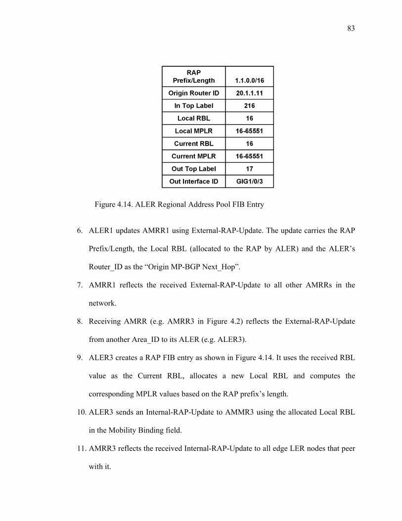
83
Figure 4.14. ALER Regional Address Pool FIB Entry
6. ALER1 updates AMRR1 using External-RAP-Update. The update carries the RAP
Prefix/Length, the Local RBL (allocated to the RAP by ALER) and the ALER’s
Router_ID as the “Origin MP-BGP Next_Hop”.
7. AMRR1 reflects the received External-RAP-Update to all other AMRRs in the
network.
8. Receiving AMRR (e.g. AMRR3 in Figure 4.2) reflects the External-RAP-Update
from another Area_ID to its ALER (e.g. ALER3).
9. ALER3 creates a RAP FIB entry as shown in Figure 4.14. It uses the received RBL
value as the Current RBL, allocates a new Local RBL and computes the
corresponding MPLR values based on the RAP prefix’s length.
10. ALER3 sends an Internal-RAP-Update to AMMR3 using the allocated Local RBL
in the Mobility Binding field.
11. AMRR3 reflects the received Internal-RAP-Update to all edge LER nodes that peer
with it.

84
12. Receiving LER nodes (e.g. LER33 in Figure 4.2) create their own RAP FIB entries
based on the RAP Prefix/Length and the received RBL.
This process is repeated by every LER in the network and results in the
distribution of the RAP and RBL/MPLR information to all LER and ALER nodes. In
contrast to the Mobility Bindings related to the actual mobile devices the RAP Binding
information is static. The only changes to it take place when the RAP is decommissioned
(withdrawn), moved to another LER or when the RAP prefix’s length changes. The
procedure to withdraw the RAP follows the same steps but is carried out using the MP-
UNREACH-NLRI messaging (Appendix A).
The RAP Prefix/Length and RBL/MPLR distribution process is illustrated in
Figure 4.15.
Figure 4.15. Mobility Pool Binding Distribution Process

85
4.3.3.2. Ingress LER Address Lookup
The purpose of using the Regional Address Pools is to eliminate the discovery steps when
forwarding traffic to a newly registered mobile device. The result of the Mobility Pool
Binding distribution process is that shortly after the network provisioning every ingress
edge LER node in the network has information about all RAPs including their
Prefix/Length and the associated RBL and MPLR values.
It is however important to note that RBL or MPLR may not be used to identify
any particular individual mobile device as the RBL is associated with the RAP’s Start
Address (not allocated to mobile devices) and the MPLR is a range of labels.
The ingress MSF LER uses the following address lookup and Mobility Pool Label
selection procedure when it needs to forward traffic to an individual IP address that is
part of the RAP present in its routing and forwarding tables. These steps assume that a
mobile device has registered with a LER node (in this case egress LER) and has been
allocated an IP address from a RAP and a Mobility Label from the MPLR associated with
that RAP.
1. Ingress MSF LER (e.g. LER33 in Figure 4.2) receives an IP packet addressed to a
mobile device registered with the egress LER (e.g. LER12 in Figure 4.2). If no
matching RAP is present in the Ingress LER’s routing table, the LER executes a
Start-Up procedure with the discovery steps (described in Section 4.3.1). Otherwise,
2. LER locates the matching RAP Prefix/Length and RBL information in its
routing/forwarding tables.
3. LER computes the value of the RAP offset (RO) for the destination IP address
using the XOR operation on the RAP’s Prefix and the destination IP address values.

86
4. LER computes the individual Mobility Pool Label (MPL) to use in the outgoing
MPLS packet’s label stack. The MPL is determined based on the RBL for the RAP
and the RO for the destination IP address.
5. When the packet is switched by the ALER node (at the terminated LSP segment) it
allocates the MPL for the outgoing packet based on the matching Local MPLR in
the RAP FIB entry. The following two cases exist:
a. If no specific Mobility Binding entry matching the individual destination IP
address of the mobile device exist (meaning that the mobile device has not
moved out of the control of the original MSF that owns the RAP from which the
device received its IP address), the allocated outgoing MPL comes from the
Current MPLR that is associated with the Local MPLR to which the incoming
MPL used in the packet belongs. The outgoing MPL must have the same RO
relative to the Current RBL as the incoming MPL has relative to the Local RBL.
b. Otherwise, the outgoing MPL is taken from the individual FIB label trail entry
created for the device as a result of its movement (see later in text).
6. The same process is repeated by the receiving ALER node which switches the
packet to the edge LER node that owns the RAP.
The receiving edge LER (egress) node locates its local FIB entry that is associated
with the mobile node’s IP address. This FIB entry has been initiated at the time the
mobile device registered with the MSF. The Mobility Label for the device has been
assigned from the MPLR associated with the RAP from which the IP address for the
device was allocated. This MPL (or in this case the Mobility Label) has been computed

87
by the MSF based on the RBL assigned to the RAP and the RO of the IP address
allocated to the device from the pool.
4.3.3.3. Start-Up Sequence with Regional Address Pools
These steps are performed when a new mobile device registers with the serving MSF in
an edge LER node. Note that by that time the Mobility Pool Binding distribution process
described in Section 4.3.3.1 above will have already taken place. Consider the H-MLBN
shown in Figure 4.2, where a mobile device is turned on in one of the RAN cells in
MR12.
1. MN initiates the MSF Discovery and receives the Virtual Link Layer and IP
Addresses of the serving MSF located in LER12.
2. MN initiates the MSF Registration and receives its IP address from the MSF. This
IP address is allocated from the corresponding Regional Address Pool (RAP). The
registration messaging also includes the Area ID information. In a start condition
the mobile device must use the Area ID value of 0. In response the MSF
communicates to the mobile a new Area ID value of 1 (LER12 serves MR12 in
Area 1) and other related information (see Appendix A).
3. LER12 allocates a Mobility Pool Label (MPL) for the mobile device from the
MPLR associated with the RAP from which the device received its IP address. This
MPL is computed using the RAP Offset (RO) for the allocated IP address and the
RAP Base Label (RBL) for the RAP.
4. No further updates are required. At this time the mobile device may be reached
from any part of the H-MLBN using the forwarding steps described in Section
4.3.3.2 above.

88
Note that as long as the mobile device remains in its original Mobility Region
(MR12 in Figure 4.2.) no additional network updates are necessary to locate the device.
4.3.4. Hand-off Processing with Regional Address Pools
With Regional Address Pools there are no changes to the MSF-Local hand-off as
described in Section 4.3.2.1.
4.3.4.1. Inter-MSF Intra-Area RAP Hand-off
Consider the H-MLBN shown in Figure 4.2, where a mobile device moves from a RAN
cell in MR12 to a RAN cell in MR13 during its active life. The device is addressed with
an IP address allocated from the RAP controlled by MSF of LER12.
1. MN initiates the registration with the new MSF in LER13 and communicates its IP
address and the last Area ID value of 1 in the process. LER13 also uses the same
value in the registration and keepalive messaging with the MN.
2. LER13 recognizes that the MN is not a new device (Area ID is not equal to 0) and
that the MN is addressed with an IP address that does not fall into the RAP range
controlled by the local MSF.
3. LER13 allocates a new Local Mobility Label and creates a Mobility Binding that
maps the MN’s IP address and the Mobility Label.
4. LER13 updates AMRR1 with the Mobility Binding for the MN including the new
Mobility Label and the Area ID value of 1 received from the MN using internal
update.
5. AMRR1 reads the Area ID value and compares it with the last recorded Area ID for
the MN. If the values are the same, AMRR1 reflects the Mobility Binding to

89
ALER1 without looking up the LRL and any further update action towards other
peer AMRR nodes. AMRR1 may also reflect the binding to LER12 since the
“Origin MP-BGP Next-Hop” changed in the Mobility Binding from LER12 to
LER13 Router ID.
6. ALER1 receives the internal update and creates a new individual label trail record
for the MN in its FIB.
a. ALER1 locates the FIB record for the RAP to which the MN’s IP address
belongs.
b. ALER1 computes the RO of the MN’s IP address within the RAP by the XOR
operation.
c. ALER1 computes the individual Local MPL value for the MN by using the
RBL in the RAP’s FIB record and the RO for the MN’s IP address.
d. ALER1 creates a new FIB label trail record that associates the top MPLS label
(determined based on the Router ID of LER13 listed in the “Origin MP-BGP
Next_Hop” of the received Mobility Binding for the MN), the Local Mobility
Label (determined by computing the Local MPL from the MPLR associated
with the RAP record matching the MN’s IP address) and the Current Mobility
Label (received in the Mobility Binding Update from LER13)
7. CN in MR33 continues to send packets to the IP address of the MN. Both LER33
and ALER3 use their existing label stacks to forward the packets onto the LSP
leading to ALER1. These label stacks are based on the Mobility Pool Binding
associated with the RAP to which the MN’s IP address belongs.

90
8. ALER1 receives the MPLS packet and pops the top label (this is the incoming top
label associated with its own Router ID). Then ALER1 reads the Mobility Label
and looks up its FIB to find the trail record with the matching Local Mobility Label
value. This record was created in step 6 above. Once the record is located ALER1
swaps the packet’s Mobility Label with the value of the Current Mobility Label and
pushes the associated Out Top Label onto the label stack. The top label will be the
one associated with the Router ID of LER13 based on the “Origin MP-BGP Next-
Hop” in the received Mobility Binding (step 6).
9. LER13 pops the outer label (in some cases this label may be replaced by an implicit
null label by ALER1 as it may be the Penultimate Hop for this LSP). LER13 reads
the Mobility Label, looks up its MSF database and locates the record associated with
the mobile node. This record may include all the necessary layer 2 information
specific to the RAN in which the mobile is located. The packet is then forwarded out
the logical layer 3 interface associated with the mobile node.
This hand-off is illustrated in Figure 4.9. Note that the ALER1 node performs
additional internal processing steps to compute the MPL for the MN and map it to the
new Current Mobility Label received in the binding update for the MN.
4.3.4.2. Inter-MSF Inter-Area RAP Hand-off
The Inter-MSF Inter-Area RAP hand-off process is the same as described in Section
4.3.2.3 with a slight change in step 34 where ALER3 is required to perform the RAP
related internal processing as described in Section 4.3.4.1 above (step 6).

91
4.3.5. Discussion
4.3.5.1. Need for AMRR
The main function of AMRR nodes is to act as a centralized control plane entity within a
Mobility Area. This involves reflecting of internal updates from the LER nodes to the
ALER node, processing of external updates from the local ALER node, reflection of
external updates from outside the area to the ALER node, processing of internal updates
from the ALER node and generation of Mobility Binding and LRL requests and replies.
A separate AMRR node does not participate in packet forwarding and offloads these
functions from the ALER nodes. This allows distribution of processing load and
increased scalability. Figure 4.16 shows the state diagram of the interactions among the
LER, ALER and AMRR nodes.
At the same time the presence of AMRR requires additional signaling steps
during the update process and increases the complexity of the overall scheme. It is
important to note that the functions of the AMRR node may be combined with the
functions of the ALER node. This will avoid additional update steps following the
allocation of the Local Mobility Label or reception of the Mobility Binding updates from
outside the area. Clearly this will also increase the processing power requirements for the
ALER nodes. In addition, implementation of certain architectural requirements such as
survivability and load distribution may be complicated without a separate control plane
layer represented by the AMRR nodes.

92
Figure 4.16. State Diagram of Interactions between MN, LER, AMRR and ALER

93
4.3.5.2. Survivability and Load Distribution
In analyzing the H-MLBN architecture, natural questions to ask are: “what happens if an
AMRR fails?” and “what happens if an ALER fails?”. The ready answer is to use pairs of
AMRRs and ALERs in the solution. However this also brings up the information
synchronization and processing load control issues. The synchronization of information
requires updating of both of the AMRR and ALER nodes in the high availability pair so
that the fail-over may occur with the preservation of the state information on the existing
Mobility Bindings. The load control has to do with the obvious desire to utilize the
resources of both systems involved in the high availability configuration. An example of
high availability structure is shown in Figure 4.17.
In Figure 4.17, each LER serving a Mobility Region is peering with both AMRR
nodes serving the Mobility Area: Primary AMRR and Secondary AMRR. In addition,
both ALER nodes: Primary ALER and Secondary ALER peer with both AMRR nodes,
and the AMRR nodes peer with each other and the AMRR nodes in other Mobility Areas.
If a mobile device registers with the MSF in LER11, the internal Mobility
Binding update is sent to both AMRR nodes, and this update is reflected to both ALER
nodes. The ALER nodes allocate the Local Mobility Labels and update both AMRR
nodes using the external update. The AMRR nodes now have the Mobility Binding
information for the mobile device represented by two ALER nodes for the requests from
outside the area. At this point the AMRR nodes may service the requests from outside the
area by replying with the Mobility Bindings that contain the Router IDs of both ALER
nodes following a certain distribution algorithm (for example, some form of a round-
robin Router ID selection). This allows for load distribution among the two ALER nodes.

94
If one AMRR node fails the peering sessions with the corresponding LER, ALER
and other AMRR nodes will also fail and will be detected by the peering nodes. The
remaining AMRR will have all the required information and is still able to serve the area.
If one of the ALER nodes fails, the corresponding failure of the MP-BGP peering
sessions will be detected by both AMRR nodes. The AMRR nodes in turn may issue a
special blanket update message containing the Router ID of the remaining ALER node to
all peering AMRR nodes in other areas to use that Router ID in all Mobility Bindings
received from the area. Once the ALER nodes in other areas are updated the network
wide fail-over to the remaining ALER node in the local Mobility Area may take place. It
is important to note that the ALER failure update message does not need to reach all LER
nodes in all areas, just the ALER nodes need to be updated. The redirection of traffic is
then achieved by using the segmented LSPs that terminate at the surviving ALER node.
Figure 4.17. High Availability Configuration for Mobility Area

95
4.3.5.3. Scope of Mobility Labels
The Mobility Labels are allocated in two places in the H-MLBN – the edge level LER
nodes and the aggregation level ALER nodes. The LERs allocate Mobility Labels upon
registering a mobile device and use internal updates to communicate the associated
bindings to the AMRR. If there is a CN in the same Mobility Area that wishes to
communicate with a registered MN, the LER serving the CN may issue a Mobility
Binding request to the AMRR. The AMRR in this case will reply with the Mobility
Binding containing the Router ID of the originating LER as the value of the “Origin MP-
BGP Next-Hop”. Thus the LSP carrying the traffic between MN and CN will terminate at
the two edge level LER nodes. If this LSP needs to pass through the ALER node (due to
the physical connectivity requirements) the ALER node will not need to examine the
Mobility Label and switch the packets using only the top labels associated with the
Router IDs of the two edge LER nodes.
Thus the Mobility Labels allocated by the edge level LERs are only scoped to the
local Mobility Area. Their uniqueness is guaranteed by the fact that they are always
associated with the unique Router IDs of the LER nodes and the corresponding top level
labels. This also means that these labels are locally significant to the edge LER nodes. In
other words, if two LERs assigned the same value of the Mobility Label to two different
MNs and these MNs need to communicate with each other – this situation does not
present a conflict. The Mobility Label and the top label associated with the far end Router
ID will be used to send traffic, and the Mobility Label received in the incoming packet
will be used to lookup the IP address of the locally registered MN and to take any further
required local processing action.

96
The ALERs allocate a Local Mobility Label when an internal or external Mobility
Binding update is received. This Local Mobility Label is used to represent the internal
MNs to other Mobility Areas as well as to represent the external MNs to the local area.
Thus the Local Mobility Labels are only significant within the ALER nodes and their
uniqueness is controlled by the label allocation process within the ALER. These labels
are only scoped to the path between the two ALER nodes from different Mobility Areas.
In other words, if two edge LER nodes within an area allocated the same Mobility Label
value to two different MNs and CNs from outside the area need to communicate with the
MNs via the ALER – this situation does not present a conflict. This is because the ALER
allocates two different Local Mobility Labels to the Mobility Bindings associated with
the MNs and keeps the label trail in its FIB linking the Current Mobility Label allocated
by the edge LER to the Local Mobility Label. This Local Mobility Label along with the
ALER Router ID (as opposed to the edge LER Router ID) is used in the Mobility
Bindings sent to other areas. As MNs move within the area, the value of the Current
Mobility Label is updated using internal updates and the value of the Local Mobility
Label does not change. This results in no need to update the rest of the network when
MNs move within the area.
The situation is reverse for the case when external MNs are represented in the
local area by the Local Mobility Label assigned by the ALER and communicated to the
edge LERs using the internal update via the AMRR node. As the Mobility Labels for the
MN change (due to the movements between the areas), the ALER updates the label trail
and no further internal updates to the LER nodes are required – the existing Local
Mobility Label is used.

97
It is important to note that in some cases the scope of the Mobility Labels
assigned by the ALER nodes may change and may extend to certain edge LER nodes. An
example of this is when an edge LER node is or connects to the service provider’s
Internet peering point. In this case the ALER nodes in other areas may communicate their
Local Mobility Labels representing the MNs within their areas directly to such LER
node. The uniqueness of labels is guaranteed by the fact that they are always associated
with the unique Router IDs of different ALER nodes and the corresponding top labels to
reach these Router IDs.
4.3.5.4. Scope of Mobility LSPs
The segmented LSP model (Figure 4.4) avoids the requirement to update all edge level
LER nodes in the network when MNs move within the Mobility Areas or between the
Mobility Areas. The scope of the Mobility LSP is controlled by the Router ID used in the
corresponding Mobility Binding as the value of the “Origin MP-BGP Next-Hop”. In the
segmented model the Mobility LSPs are always scoped to between the two edge LER
nodes for intra-area traffic. For inter-area traffic the path is segmented and the Mobility
LSP segments are scoped to between the near-end edge LER and the near-end ALER,
between the two ALERs and between the far-end ALER and the far-end edge LER.
In cases where the Mobility Label assigned by an ALER node extends directly to
an edge LER node (for example, the Internet peering point) in a different area, the LSP
scope is also different. In this case the Mobility LSP extends from the edge LER node via
the near-end ALER node (without the termination and the corresponding Mobility Label
lookup) to the far-end ALER node where the segment is terminated and the new segment
associated with the current Mobility Label is originated. It is important to point out that

98
the Mobility LSP scope is flexible and may be controlled by the logic in the AMRR
function.
4.3.5.5. Mobile Node Multi-Homing and Traffic Continuity
The preservation of traffic continuity during the mobile node movements is a very
important requirement and is achieved by coordinating the layer 2 hand-off with the layer
3 hand-off processes. The layer 2 hand off takes place when a mobile node transitions
from one RAN base station to another and is usually based on the radio signal level that
the MN receives from different base stations.
Regardless of the type of the layer 2 hand-off (hard or soft) the important point is
that there is a period of time during which the MN has connectivity to two different RAN
base stations. If the two base stations in question are associated with the same layer 3
domain or sub-net (such as the same layer 3 logical interface of the MSF) by way of the
wire-line layer 2 grooming network configuration, the layer 2 hand-off is transparent to
the network layer and the traffic continuity is only a function of the RAN hand-off
process.
If the layer 2 hand-off results in the MN moving to a different layer 3 domain, the
traffic continuity also depends on the layer 3 hand-off process. The coordination between
the layer 2 and layer 3 hand-off processes may be explicit (based on the cross layer
signaling) or implicit (based on the built-in mobility management scheme properties).
There is also some level of coordination within the MN itself. For example, when the MN
detects a stronger radio signal or in the process of switching the RAN types (e.g., cellular
to Wi-Fi), the hand-off logic may invoke the new layer 3 Discovery and Registration on

99
the new RAN while the old RAN connection is maintained (radio signal quality
permitting).
Thus in the context of H-MLBN, traffic continuity and MN multi-homing may be
considered for the three hand-off modes (MSF-Local, Inter-MSF Intra-Area and Inter-
MSF Inter-Area).
During the MSF-Local hand-off (Figure 4.8), while the MN is multi-homed to two
RAN base stations, traffic continuity is controlled by the MSF layer 3 tracking function.
In its simplest form the continuity logic may wait until the mobile node sourced IP
packets start arriving on the new layer 3 logical interface (similar to Cellular IP [9]) and
then update the local registration record for the MN with the new interface ID. A more
elaborate scheme may involve packet replication toward the MN across the two layer 3
logical interfaces for some period of time (maintaining a registration record with two
layer 3 interface IDs until no activity is detected by the tracking function on the old
interface ID).
During the Inter-MSF Intra-Area hand-off (Figures 4.9, 4.10), the MN is multi-
homed to two RAN base stations that are under control of two different MSFs. The traffic
continuity depends on the intra-area Mobility Binding update process. The basic form of
traffic continuity involves the MN detecting a new RAN and initiating the Discovery and
Registration with the new MSF while maintaining connectivity to the old MSF. While the
intra-area update is taking place (AMRR update with the current Mobility Label by the
new LER and the ALER update) the traffic to the MN may be delivered via the old
Mobility LSP segment (from ALER to the old LER). Once the ALER has been updated
with the new Current Mobility Label and the FIB label trail record is updated, the traffic

100
may switch to the new Mobility LSP segment (New LSP in Figure 4.9). A more
sophisticated scheme may involve temporary packet replication at the ALER over the two
existing Mobility LSP segments.
During the Inter-MSF Inter-Area hand-off (Figure 4.11, 4.12), maintaining the
traffic continuity is most difficult and depends on the inter-area update process. As in the
above discussion, the MN detects a new RAN and initiates the Discovery and
Registration with the new MSF while maintaining connectivity to the old MSF. The inter-
area update process may be considered as a two-stage process.
The first stage involves the internal AMRR update by the new LER, the combined
LRL request and the Mobility Binding update from the new AMRR to the old AMRR
(based on the value of the Area ID received from the MN) and the external update of the
old ALER by the old AMRR.
The second stage consists of the Mobility Binding update from the new serving
AMRR (AMRR2 in Figure 4.11) to the AMRR identified in the received LRL (AMRR3
in Figure 4.11) and the external update of the ALER by the AMRR in the area serving the
CN (ALER3 in Figure 4.11).
Until the completion of the first stage the traffic to the MN may be delivered by
the original old Mobility LSP (LER-ALER3-ALER1-LER in Figure 4.11). Immediately
after the completion of the first stage, right after the old ALER (ALER1 in Figure 4.11)
updates its FIB label trail, the traffic to the MN may be delivered using the interim
Mobility LSP (shown in Figure 4.12 – LER-ALER3-ALER1-ALER2-LER). And after
the completion of the second stage, when ALER3 updates its FIB label trail, the traffic
may switch to the new Mobility LSP (LER-ALER3-ALER2-LER).

101
Clearly the most vulnerable time period for the Inter-MSF Inter-Area hand-off is
between the start of the layer 2 hand-off and the moment when the first stage of the inter-
area update is completed. Compared to the Intra-Area hand-off the first stage involves an
extra inter-AMRR update. In addition during the time period between the completion of
the first stage and the completion of the second stage the traffic will be temporarily
following a sub-optimal forwarding path.
4.3.5.6. Role of Area-ID
The purpose of the Area ID is to track the last Mobility Area visited by a mobile node
and to identify which Mobility Areas requested Mobility Binding information for the
mobile node during the lifetime of the Mobility Binding. The last visited Area ID is
communicated to the MN by the LER during the registration process with the MSF. Area
ID may be stored in the MN’s memory and included into the MSF Discovery and
Registration messaging.
Initially in a start-up state, MN uses the Area ID value of 0 in the MSF
registration messaging. If the LER receives the Area ID value of 0 from the MN, the
serving LER updates the MN with its own Area ID and uses its own Area ID during the
internal update of the AMRR. On all subsequent moves, the MN should be using the
Area ID value other then 0. If the serving LER receives the Area ID value that is not
equal to 0 from the MN, the LER passes the received Area ID value unchanged to the
AMRR node during the internal update.
When the AMRR node receives an internal Mobility Binding update from an LER
node it must check the Area ID value in the received information. If the Area ID equals
its own Area ID it reflects the update to the ALER node and takes no further action.

102
Otherwise, the AMRR sends the LRL request to the AMRR identified by the originally
received value of the Area ID, re-writes the received Area ID with its own and reflects
the internal update to the ALER. The Area ID check by the AMRR is only performed on
the internal Mobility Binding updates. When an external update is received by an AMRR
node the Area ID in the Mobility Binding is simply stored in the MN binding record.
The LRL received in the reply from another AMRR node contains a list of Area
IDs from which the requests for the Mobility Binding information for the MN in question
were received. The AMRR node then sends unsolicited Mobility Binding updates to the
corresponding AMRR nodes with the listed Area IDs (as discussed in the Inter-Area
hand-off).
If an AMRR node receives a Mobility Binding request from another peer AMRR
node it should send a positive reply only for the locally stored Mobility Bindings that
have their Area ID values equal to the Area ID of the responding AMRR node. Otherwise
the AMRR should send a negative reply to the received request. The Area ID (AID)
processing is summarized in Figure 4.18.
Figure 4.18. Area ID Processing Logic.

103
4.3.5.7. Mobility Binding Lifetime and Transient Conditions
Clearly, Mobility Bindings should not be allowed to exist in the network forever and
must have an expiration time associated with them. This time interval (referred to as a
Lifetime) may be carried explicitly with each Mobility Binding or set as a network wide
parameter for all bindings. In any case the Lifetime starts counting down from the
moment the binding information has been received by a network node (LER, AMRR,
ALER). Once the Lifetime expires the binding is silently removed from each node’s
database.
Given that the Mobility Bindings have a finite Lifetime, there are some specific
transient conditions that may lead to potentially significant interruption in traffic delivery
to mobile nodes. One such condition is when during an active Mobility Binding Lifetime
a mobile device that has previously been registered in a given Mobility Region resets,
and shortly thereafter a mobile user moves into another Mobility Area.
In this case the old local AMRR and ALER nodes still count down the Lifetime for the
MN’s binding marked with their own Area ID (thinking that the MN still exists in the
local area). The AMRR, ALER and LER nodes in other areas that the MN has been
communicating with, also have the “stale” binding and the associated label stack leading
to the old local ALER node.
When the MN goes through the start-up mode in the new region and new area, it
must use the Area ID value of 0. The new local LER will re-write this Area ID with the
new Area ID and send an internal update to the new AMRR and so on (as in the
described start-up sequence). Since the new AMRR may not have any old active bindings
associated with the MN, it stores the newly received binding information ready to reply

104
to the requests from internal and external nodes. The issue is that due to the fact that a
stale binding may still exist in other external LER and ALER nodes pointing to the old
local ALER for the MN, and until this binding expires the traffic to the MN will be
directed to a wrong place.
To solve this problem the Mobility Binding Withdrawal mechanism is required.
Clearly to be efficient the withdrawal should not be based on flooding the entire network
with the MP-BGP Update (carried in the MP-UNREACH-NLRI attribute with the
encoded Mobility Binding that is being withdrawn).
In order to facilitate the scalable distribution of withdrawal messages, the LRL
(Last Requestor List) processing is enhanced to include two types of LRLs at the AMRR
level: External LRL (eLRL) and Internal LRL (iLRL).
The eLRL is the same as described earlier (LRL) and consists of the Area IDs
from which the requests for the Mobility Binding in question have been received by an
AMRR node from external AMRR nodes during the Lifetime of the binding.
The iLRL is also maintained by an AMRR node and is a list of the Router IDs of all LER
nodes internal to an area which originated Mobility Binding requests for the binding in
question. The Mobility Binding Withdrawal sequence follows the steps below:
1. When an LER node detects loss of communication with a registered MN (based on
the keepalive mechanism) it sends an internal Mobility Binding Withdrawal update to
the local AMRR using the MP-UNREACH-NLRI encoding (see Appendix A). The
LER clears the Mobility Binding and the registration record from its memory.
2. The local AMRR receives the withdrawal message and looks up the Mobility Binding
record. If at this time the AMRR finds an existing Mobility Binding associated with a

105
Router ID of another LER and different from the LER that originated the withdrawal,
the AMRR ignores the received withdrawal and takes no further action.
3. Otherwise, if the Mobility Binding exists and the “Origin MP-BGP Next-Hop” value
matches the Router ID of the LER originating the withdrawal, the AMRR locates the
iLRL and reflects the withdrawal update to all LERs whose Router IDs have been
found in the iLRL. In addition, the AMRR locates the eLRL and forwards the
withdrawal update to all AMRR nodes whose Area IDs have been found in the eLRL.
AMRR removes the binding.
4. Each AMRR node that receives the Mobility Binding withdrawal update from another
AMRR looks up the iLRL and forwards the update to all LERs with the Router IDs
found in the list. The AMRR then clears the Mobility Binding.
5. Each LER that receives the Mobility Binding withdrawal update clears the Mobility
Binding and the associated label stack from its memory.
The result is that the network may be updated in a scalable manner before the
Mobility Binding Lifetime expires. Step 2 in the above sequence is designed in order to
prevent the unnecessary inter-area withdrawals (it implies that the MN has re-registered
with another LER local to the same or another area and the Intra-Area or Inter-Area
hand-off sequence has been executed before the withdrawal update has been received).
Clearly there has to be a defined relationship among the following time intervals:
Mobility Binding Lifetime (L), Registration Dead Time (D) and the Expected Re-
registration Time (R). In general this relationship should be expected to follow: L >> D
>> R. The Mobility Binding Withdrawal process state diagram is shown in Figure 4.19.

106
Figure 4.19. Mobility Binding Withdrawal Process.
4.3.6. Applications for Mobility Labels
4.3.6.1. RAN Differentiation
In order to speed up traffic processing at the MPLS LER nodes facing the RAN the
Mobility Label assigned by the LER node and used in the received packet’s MPLS label
stack in the packets destined to the mobile node may be assigned such that the layer 2
properties of the packet to be forwarded to a particular RAN type are easily identified and
the associated protocol headers are pre-constructed and stored in the LER memory along
with the mobile node’s registration record.
For, example if an LER is serving different RAN types such as CDMA, GSM,
Wi-Max or Wi-Fi, each of the served RAN technologies may require different types of
layer 2 packet encapsulations and addressing. At the time when a mobile node registers

107
with the serving MSF, a Mobility Label is assigned and associated with the registration
record including at a minimum the mobile node’s IP address, layer 2 address, Area ID
and the associated layer 3 logical interface of the MSF. In addition to this information the
LER may pre-construct a RAN-specific layer 2 protocol header, including the
encapsulation and addressing information, and attach it to the record.
When a MPLS packet arrives at the LER, the LER pops the top label, reads the
Mobility Label and proceeds directly to building the RAN-specific layer 2 packet
followed by the IP header and payload using the information stored in the registration
record and identified by a fixed-size locally significant Mobility Label.
Without the pre-construction of the layer 2 information an LER would have to
lookup all the components of the packet separately taking more time to switch the packet
to the RAN. The local processing of the Mobility Label for the RAN differentiation
offers a simple and effective way of reducing the packet processing time.
4.3.6.2. Normalization of IP Address Lookup Time
The MLBN is capable of supporting the mobile devices addressed using IPv4 or IPv6.
IPv4 and IPv6 addresses are different in length (32 bits for IPv4 and 128 bits for IPv6)
and are usually stored in different memory tables at the LERs. Clearly the IP address
lookup times depend on the size of the address field and the size of the storing database.
The presence of the fixed-length (20 bits) locally significant and unique Mobility Label
allows to normalize the IP address search time (lookup time) at the MPLS LER serving
the mixed IPv4/IPv6 mobile environment. When a MPLS packet arrives at the LER, the
LER uses the 20-bit Mobility Label to locate the IPv4 or IPv6 address of the mobile node

108
in the associated registration record thus normalizing the processing time for both
protocol stacks.
4.3.6.3. Network Virtualization
The presence of Mobility Labels and the corresponding MPLS label stack allows
utilization of the same MLBN infrastructure not only for providing efficient support for
various access RAN types but also to enable virtualization of services.
As an example consider a MLBN providing services to multiple wireless carriers
using the same MPLS network. Each carrier may have multiple RAN types and may be
using unique or overlapping (private) IP address ranges for their mobile devices. In this
case Mobility Labels (or even a special label stack – including the Carrier Label and the
Mobility Label) may be used to differentiate among the multiple carriers and their RANs.
This is similar to the layer 3 MPLS VPN service [4] and requires the corresponding
support in MP-BGP for the address space differentiation and information partitioning
(such as Route Distinguishers and Route Targets).
4.3.6.4. Inter-Carrier Roaming
This use of Mobility Labels involves a scenario where a mobile device assigned a carrier-
specific unique IPv4 or IPv6 address moves from the MLBN operated by one carrier to
the MLBN operated by another carrier. If the mobile device is in an active
communication session and needs to retain its fixed IP address a Mobility Label based
interconnect between the service providers may enable this type of roaming.
In this architecture roaming between the service providers is supported by
establishing the mobility enabled MP-BGP peering points between the provider

109
networks. These peering points may be established between the special types of nodes
referred to as the MLBN Border Edge Router (MBER). These nodes perform a function
similar to the ALER nodes and peer to their local AMRR nodes.
Figure 4.20. Inter-Carrier Roaming with H-MLBN
Consider Figure 4.20, where two service providers are connected using the
corresponding MBER nodes. The MBERs are peered with each other and with their local
AMRR nodes. When a mobile node roams from a RAN served by one provider to a RAN
served by another provider, the MN initiates the layer 2 hand-off during which it
identifies the move to another service provider. The MN perform the MSF Discovery and
Registration as in the “start-up condition” and registers with the MSF in LER11 of
provider 2. The provider’s LER updates the AMRR using the inter-carrier update type
(indicated by the Update Type field in the Mobility Binding) and the AMRR reflects the

110
update to the ALER. ALER allocates the Local Mobility Label and updates the MBER
node via the corresponding AMRR (or optionally directly – not shown in Figure 4.20).
The MBER2 node stores the update, allocates its own Local Mobility Label and
updates its peer MBER1 using its own Router ID as the “Origin MP-BGP Next Hop” in
the Mobility Binding. The MBER1 then updates its own AMRR which in turn updates
the ALER node using MBER1 Router ID. Traffic delivery to the MN follows the
segmented Mobility LSP: ALER1_Provider1-MBER1-MBER2-ALER1_Provider2.
The segments of the LSP are terminated at each node and the next segment is
identified by the value of the Local Mobility Label. When the MN moves within the
provider 2 MLBN, the MSF-Local, Intra-Area and Inter-Area hand-off procedures are
performed and provider 1 does not need to be updated. It is important to note that in order
to ensure optimal traffic routing the peering MLBN providers must identify to each other
their respective mobility address spaces.
4.4. Chapter Summary
The Hierarchical Mobility Label Based Network (H-MLBN) represents a mobility
management system in which mobility control plane is fully integrated with MPLS
forwarding plane resulting in optimal traffic delivery to mobile devices. H-MLBN
provides support for macro- and micro-mobility for IPv4 and IPv6 mobile hosts and
routers under a common MPLS-based control plane without a need for Mobile IP.
At the forwarding plane H-MLBN is designed to avoid explicit MPLS LSP
creation, teardown and redirection following the movements of mobile devices. On the
contrary H-MLBN relies on the use of pre-constructed full logical mesh of LSPs
connecting all LERs and LSRs in the network and managed by the Label Distribution

111
Protocol. The task of mapping mobile prefixes to the existing LSPs is performed by the
H-MLBN mobility control plane using a modified MP-BGP protocol. This mapping
however is not a simple IP prefix to LSP label mapping. Such a mapping approach would
require that the IP addresses of mobile devices are looked up at every intermediate H-
MLBN node thus resulting in a significant increase in a processing load and reduction in
scalability.
A Mobility Label is introduced and associated with every mobile prefix and the
Router ID of an H-MLBN node that is used to reach the mobile device. This Mobility
Label is used as the second label in the MPLS label stack allowing intermediate H-
MLBN nodes to avoid IP prefix lookups and just perform conventional MPLS level
operations (pop, swap, push) while forwarding traffic to mobile devices over a set of LSP
segments.
The control plane architecture of H-MLBN is constructed in a hierarchical
manner providing support for micro-mobility. Micro-mobility is achieved through the
support of MSF-Local and Intra-Area layer 3 hand-offs. MSF-Local hand-off is
performed locally by an LER node and does not require any network updates and
associated state changes. Intra-Area hand-off is performed within a Mobility Area by an
interaction between LER, AMRR and ALER nodes, and does not require network
updates and state changes outside of the Mobility Area.
The regionalized network architecture supported by specific control plane
mechanisms such as mobile device to MSF-logical-interface association tracking,
mobility area internal updates, on-demand mobility binding requests, Area ID processing
and segmentation of mobility LSPs, allows to minimize the frequency of network-wide

112
updates and eliminates the need to share the visitor information on all network nodes
participating in mobility management.
Although existing Mobile IP based mobility management schemes allow for route
optimization the specific mechanisms involved in these solutions are often difficult for
practical implementation as they impose significant requirements on the fixed
correspondent nodes and in turn generate sophisticated security schemes and
requirements on mobile devices, home agents and fixed devices.
H-MLBN avoids these complexities and allows for optimal traffic delivery. The
introduction of the hierarchy does not result in single points of failure and bottlenecks as
the mobility related information and processing load may be flexibly distributed by the
control plane.

113
CHAPTER 5. SYSTEM MODEL
This chapter presents a system model for the hierarchical Mobility Label Based Network.
We develop the mobile node movement model as well as the traffic models for the
control plane and the forwarding plane.
5.1. Movement Model
5.1.1. Mobility Region Structure
A Mobility Region (MR) consists of a number of RAN cells. Each cell is represented by
a hexagon with radius as shown in Figure 5.1a. The height of a cell is rh = rp
3=2rh = rp
3=2. The
cells in the MR are arranged in rings as shown in Figure 5.2. The size of the MR is
determined by the number of rings . Each cell in the MR is labeled as SliSli, where
1 · i · Nl1 · i · Nl is the cell number in the ring and 1 · l · L1 · l · L is the ring number. The rings are
counted from 0 with the cell S01S01 in the center of the MR. The number of cells in a given
ring can be expressed as Nl = 6l; l = 1; 2; 3:::LNl = 6l; l = 1; 2; 3:::L. Thus, the total number of cells in the
Mobility Region can be written as:
(1)
In the MR shown in Figure 5.2 L = 3L = 3 and N = 37N = 37. The area of the MR can be
found as follows:
(2)

114
Figure 5.1. Cell Radius (a), Movement Distribution (b).
Figure 5.2. Mobility Region L = 3; N = 37L = 3; N = 37.

115
5.1.2. Movement in the Mobility Region
Consider a mobile node (MN) that is moving from cell to cell in the Mobility Region. As
shown in Figure 5.1b once in a given cell the MN is allowed to move out of that cell in
one of the six directions with equal probability. The dwelling time TcTc of the MN in a
given cell is assumed to be exponentially distributed with parameter ¹¹. Although the
exponential cell dwelling time assumption is commonly used in the related works
(example [17]) below we provide a justification for this assumption.
5.1.2.1. Dwelling Time in a RAN Cell
Consider an application of the Random Way Point (RWP) model to the
movements of a mobile node. In the RWP model [31] a mobile makes a series of steps
from one waypoint to another where waypoints are uniformly distributed over a given
deployment region QQ. Once the initial position of a mobile node is chosen within the
deployment region, the next waypoint is chosen randomly following a uniform
distribution. The speed of movement of a mobile vsvs on a given step is constant and is
selected from a uniform distribution on [vmin vmax][vmin vmax] with vmin > 0vmin > 0. Therefore the
average duration of a step can be defined as E[¿s] = E[ls]E[ 1vs
]E[¿s] = E[ls]E[ 1vs
], where E[ls]E[ls] is the
average length of a step. Thus the RWP process is a sequence of contiguous steps from
the starting point to some destination point within the deployment region.
Consider a cell cluster of a number of cells as the RWP deployment region. For
example cells of rings l = 0l = 0 and l = 1l = 1 in Figure 5.2. We are interested in estimating the
distribution of time that a mobile spends in the cell S01S01 before exiting this cell - the cell
dwelling time TcTc. We assume that the initial position of the mobile node is inside the cell

116
of interest S01S01 and that the mobile will not remain stationary in the cell. Similarly to [32]
the number of steps NsNs that results in a mobile node exiting a convex shaped cell is
distributed geometrically:
Pr(Ns = i) = p(i¡1)s (1¡ ps)Pr(Ns = i) = p(i¡1)s (1¡ ps) (3)
Where, psps is the probability of the next waypoint being within the cell of interest
(a center cell of the RWP deployment region – a seven-cell cluster in our case). Given the
uniform waypoint distribution over the cell cluster this probability is the ratio of the area
of the cell to the area of the cell cluster. To estimate the asymptotic distribution of the cell
dwelling time we may write (for tt large):
Pr(Tc > t) ¼ Pr
µNs ¸ t
E[¿s]
=1X
i= tE[¿s]
p(i¡1)s (1¡ ps)
= p[ t
E[¿s]¡1]
s = Ae¡®t
Pr(Tc > t) ¼ Pr
µNs ¸ t
E[¿s]
=1X
i= tE[¿s]
p(i¡1)s (1¡ ps)
= p[ t
E[¿s]¡1]
s = Ae¡®t
(4)
Where, A = 1=psA = 1=ps and ® = ln(1=ps)E[¿s]
® = ln(1=ps)E[¿s]
. Thus (4) shows that the asymptotic behavior
of the tail distribution of the cell dwelling time may be thought of as approximately
exponential. The RWP process within a seven-cell cluster deployment region is
illustrated in Figure 5.4.
5.1.2.2. Inter-Cell Movements
Movements within a given cell are modeled as a Random Waypoint Process (RWP) as
discussed in section 5.1.2.1. Clearly, the RWP process is only applicable to a relatively
small coverage area simply because the random selection of a next waypoint from a

117
uniform distribution over a large area may result in a very distant waypoint and a very
long step, which would not be realistic for practical applications. In this section we
combine the RWP model within a given cell with a Random Walk model between the
cells of a Mobility Region in what we call a “Hybrid Random Waypoint Random Walk
Process” (H2RWP) in order to describe the movement of the mobile node within the
Mobility Region. The H2RWP model describes the inter-cell movements as a random
walk on a graph (see further in text) where the “thinking” times (or dwelling times)
between the random walk steps are driven by the random waypoint process within a
particular cell.
When a next RWP trajectory step results in a cell boundary transition the RWP
deployment region is “moved” to include the neighboring cells of the new cell and the
next waypoint is drawn uniformly from the new RWP deployment region. The cell
transition step is then counted as the random walk step on a graph representing a mobility
region. The H2RWP process is illustrated in Figure 5.3. Given the cell geometry shown
in Figure 5.1 and the uniform waypoint distribution assumption over a seven-cell cluster
including all immediate neighboring cells, all possible exists from a given cell to the
neighboring cells may be aggregated to the six directions shown in Figure 5.1b.
In addition, with the H2RWP model we claim that the collection of cell dwelling
times generated by a random walk of a mobile node in a Mobility Region may be
considered as a collection of i.i.d. exponential random variables. To see this we first
consider a RWP process as shown in Figure 5.4 below.

118
Figure 5.3. An Illustration of the H2RWP Process
Figure 5.4. A Random Waypoint Process

119
The RWP begins with the uniformly distributed waypoints over a deployment
region (a seven-cell cluster). Assuming that the RWP trajectory starts in the center cell at
point P0, the next waypoint (e.g. P1) is chosen independently using the uniform
distribution and thus the RWP trajectory is formed. We note that the random waypoints
themselves are i.i.d. However, the steps of the RWP trajectory are not fully independent
because the consecutive legs of the trajectory share a common waypoint. For example,
the trajectory steps f(P0; P1); (P1; P2); (P2; P3); : : : gf(P0; P1); (P1; P2); (P2; P3); : : : g are not independent.
Nevertheless, as shown in [31], if we consider a truly independent RWP (iRWP)
with a sample trajectory f(P0; P1); (P2; P3); (P4; P5); : : : gf(P0; P1); (P2; P3); (P4; P5); : : : g it can be shown that the
asymptotic expectations of the trajectory lengths of the RWP and the iRWP processes are
equal. Let, z(¿i) = k¿ikz(¿i) = k¿ik be the duration of a trajectory step ¿i = (Pi ¡ Pi¡1)¿i = (Pi ¡ Pi¡1), ZZ and Z 0Z 0 the
RWP and iRWP trajectory lengths respectively. Then:
E[Z] = limk!1
Pk=2i=1 z(¿2i¡1)
k+
Pk=2i=1 z(¿2i)
k=
E[Z 0]2
+E[Z 0]
2= E[Z 0]E[Z] = lim
k!1
Pk=2i=1 z(¿2i¡1)
k+
Pk=2i=1 z(¿2i)
k=
E[Z 0]2
+E[Z 0]
2= E[Z 0]
This shows that the asymptotic behavior of the RWP process is “mean-ergodic”.
Namely, there is no statistical difference (with respect to the mean trajectory lengths)
between considering consecutive RWP steps and disjoint iRWP steps.
Therefore, since in every cell the dwelling time of a mobile node may be
considered exponentially distributed (see Section 5.1.2.1) and the dwelling time within a
given cell is determined by the RWP steps that may be considered independent from the
RWP steps in other cells, the cell dwelling times may also be considered as independent.
In what follows we develop the Random Walk part of the H2RWP model.

120
5.1.2.3. Random Walk in a Mobility Region
We define a moment in time when the MN transitions from a standby state to an
active state as an “on-event” or visa versa as an “off-event”. The active life time of the
MN TlTl is defined as the time period between the on-event and the following off-event.
The active life time may represent the duration of time that the MN is known to (or
registered with) the network.
We assume that TlTl is exponentially distributed with parameter ¸̧. Therefore the
remaining active life time T rlT rl is also exponentially distributed with parameter ¸̧. Thus the
probability pcpc that the MN will move through a given cell can be expressed as:
pc =Pr(Trl >Tc) =
Z 1
0
[1¡FTrl(t)]fTc(t)dt =
¹
¹+¸pc =Pr(Tr
l >Tc) =
Z 1
0
[1¡FTrl(t)]fTc(t)dt =
¹
¹+¸ (5)
where FTi(t)FTi(t) and fTi(t)fTi(t) are a CDF and a PDF of the exponential distribution.
Consider a Life-to-Mobility Ratio (LMR) defined as:
(6)
where E[Tc]E[Tc] is the average cell dwelling time and E[T r
l ]E[T rl ] is the average remaining active
life time. LMR reflects the average number of cell changes per an active life time. Then
pcpc can be written as:
pc =1
1 + ½c
pc =1
1 + ½c (7)
Consider a connected graph R(V; E)R(V; E) that is constructed by connecting the centers
of the cells in the Mobility Region (Figure 5.2) using the directions of possible

121
movements of the MN from within a given cell (Figure 5.1b). The cells of the ring l = Ll = L
(shown as shaded in Figure 5.2) form the border cells of the MR. The graph R(V; E)R(V; E)
with each vertex labeled with its degree is shown in Figure 5.5.
Figure 5.5 Connected Graph Representing the Mobility Region.
The movements of the MN within the Mobility Region are modeled as a random
walk on R(V; E)R(V; E). This random walk can be represented by a Markov chain with the
stationary distribution given by:
¼u =du
2jEj¼u =du
2jEj, where
dudu - is the degree of vertex uu, and jEjjEj - is the total number of edges in R(V; E)R(V; E).
According to Figure 5.4 the set of vertices of graph RR can be written as
V = V IS
V ES
V CV = V IS
V ES
V C, where du2V I = 6du2V I = 6 (Internal vertices), du2V E = 4du2V E = 4 (Edge vertices)
and du2V C = 3du2V C = 3 (Corner vertices). In addition:
jV I j = 1 +L¡1Xl=1
6l = 3L(L¡ 1) + 1jV I j = 1 +L¡1Xl=1
6l = 3L(L¡ 1) + 1

122
jV Ej = 6(L¡ 1)jV Ej = 6(L¡ 1)
jV C j = 6jV C j = 6
The total number of edges in RR can be found using:
2jEj = jV I jdu2V I + jV Ejdu2V E + jV C jdu2V C = 6L(3L + 1)2jEj = jV I jdu2V I + jV Ejdu2V E + jV C jdu2V C = 6L(3L + 1)
Therefore the stationary probabilities are:
¼ru2V I =
1
L(3L + 1)¼r
u2V I =1
L(3L + 1)
¼ru2V E =
2
3L(3L + 1)¼r
u2V E =2
3L(3L + 1)
¼ru2V C =
1
2L(3L + 1)¼r
u2V C =1
2L(3L + 1)
We are interested in the probability of crossing of the boundary of a Mobility
Region psrpsr. This probability can be expressed as:
psr =1
3pc¼
ru2V E +
1
2pc¼
ru2V C ¼ 1
2L(3L + 1)(1 + ½c)psr =
1
3pc¼
ru2V E +
1
2pc¼
ru2V C ¼ 1
2L(3L + 1)(1 + ½c) (8)
Proposition 5.1. The number of RAN cell boundary crossings McbMcb of the MN that results
in the MN exiting the Mobility Region (including the crossing of the Mobility Region
boundary) is Geometrically distributed with parameter psrpsr:
(9)

123
Proof: If we let the random walk on graph R(V;E)R(V;E) representing the Mobility
Region progress over time, then at any point in time chosen at random (a typical time) the
probability that the MN could cross the boundary of R(V;E)R(V;E) is psrpsr. Consider a sequence
of observation intervals (steps) starting at a typical point in time. There may be (k ¡ 1)(k ¡ 1)
steps with probability (1¡ psr)(1¡ psr) each before the success on the kthkth step with probability
psr ¥psr ¥.
Proposition 5.2. The dwelling time (the time to exit) of the MN in the mobility region TrTr
is distributed exponentially with parameter ´r = ¹psr´r = ¹psr.
Proof: The dwelling time in the Mobility Region can be expressed as:
Tr =
McbXk=1
TckTr =
McbXk=1
Tck
which is a random sum of exponentially distributed i.i.d. random variables (TckTck
- cell
dwelling times) with the geometrically distributed number of terms McbMcb.
Consider a random variable:
TrjMcb=n =nX
k=1
TckTrjMcb=n =
nXk=1
Tck
which is a deterministic sum of i.i.d. exponential random variables. This sum is Gamma-
distributed with the conditional density function:
fTr jMcb=n(tjn) =¹n
(n¡ 1)!tn¡1e¡¹t; t ¸ 0fTr jMcb=n(tjn) =
¹n
(n¡ 1)!tn¡1e¡¹t; t ¸ 0
From this the probability density function of TrTr is:

124
fTr (t) =
1Xn=1
fTr jMcb=n(tjn)fMcb(n)
=
1Xn=1
¹n
(n ¡ 1)!tn¡1e¡¹t(1 ¡ psr)
n¡1psr
= ¹psre¡¹t
1Xn=1
(¹(1 ¡ psr)t)n¡1
(n ¡ 1)!
= ¹psre¡¹te¹(1¡psr )t = ¹psre
¡¹psr t ¥
fTr (t) =
1Xn=1
fTr jMcb=n(tjn)fMcb(n)
=
1Xn=1
¹n
(n ¡ 1)!tn¡1e¡¹t(1 ¡ psr)
n¡1psr
= ¹psre¡¹t
1Xn=1
(¹(1 ¡ psr)t)n¡1
(n ¡ 1)!
= ¹psre¡¹te¹(1¡psr )t = ¹psre
¡¹psr t ¥
The probability that the MN will move through a given Mobility Region during
its remaining active life time is:
pr = Pr(T rl > Tr) =
¹psr
¹psr + ¸=
1
1 + ½c=psr
=1
1 + 2½c(1 + ½c)L(3L + 1)
pr = Pr(T rl > Tr) =
¹psr
¹psr + ¸=
1
1 + ½c=psr
=1
1 + 2½c(1 + ½c)L(3L + 1)
(10)
5.1.3. Mobility Area Structure
Mobility Regions are grouped into Mobility Areas. A Mobility Region with LL rings is
approximated as a square of the same area as shown in Figure 5.6. The side of the
approximating square is a =q
3p
32
Ra =q
3p
32
R, where R =p
32
(2L + 1)rR =p
32
(2L + 1)r, and rr is the cell radius as
shown in Figure 5.1a
A Mobility Area is represented as a square with M2M2 Mobility Regions, where
M > 1M > 1. The structure of a Mobility Area is shown in Figure 5.7a. Each Mobility Region
internal to the Mobility Area has eight neighbors.

125
Figure 5.6. Approximating Square for a Mobility Region
Figure 5.7. Mobility Area (a), Connected Graph for Mobility Area (b)
The area of a Mobility Area AaAa can be expressed as follows:
Aa =9p
3
8[Mr(2L + 1)]2 ¼ 2 [Mr(2L + 1)]2Aa =
9p
3
8[Mr(2L + 1)]2 ¼ 2 [Mr(2L + 1)]2 (11)

126
5.1.4. Movement in the Mobility Area
Consider a connected graph A(V;E)A(V;E) shown in Figure 5.7b. Since, according to
Proposition 5.2, the MN’s dwelling time in a given Mobility Region is exponentially
distributed, the random walk of the MN on A(V;E)A(V;E) may be represented by a Markov
chain. Proceeding as in the case of a Mobility Region:
jV I j = (M ¡ 2)2jV I j = (M ¡ 2)2
jV E j = 4(M ¡ 2)jV E j = 4(M ¡ 2)
jV C j = 4jV C j = 4
2jEj = 4(2M ¡ 1)(M ¡ 1)2jEj = 4(2M ¡ 1)(M ¡ 1)
¼au2V I =
2
(2M ¡ 1)(M ¡ 1)¼a
u2V I =2
(2M ¡ 1)(M ¡ 1)
¼au2V E =
5
4(2M ¡ 1)(M ¡ 1)¼a
u2V E =5
4(2M ¡ 1)(M ¡ 1)
¼au2V C =
1
(2M ¡ 1)(M ¡ 1)¼a
u2V C =1
(2M ¡ 1)(M ¡ 1)
The probability of crossing of the boundary of a Mobility Area psapsa is:
psa =3
8pr¼
au2V E +
5
8pr¼
au2V C
=35pr
32(2M ¡ 1)(M ¡ 1)
¼ pr
(2M ¡ 1)(M ¡ 1)
psa =3
8pr¼
au2V E +
5
8pr¼
au2V C
=35pr
32(2M ¡ 1)(M ¡ 1)
¼ pr
(2M ¡ 1)(M ¡ 1)
(12)
Using the same line of reasoning as in Propositions 5.1 and 5.2, the number of
region transitions MrbMrb of the MN that results in the MN exiting the Mobility Area is

127
distributed as: Pr(Mrb = r) = (1¡ psa)r¡1psaPr(Mrb = r) = (1¡ psa)r¡1psa, and the dwelling time of the MN in the
Mobility Area TaTa is distributed exponentially with parameter (´a = ¹psrpsa)(´a = ¹psrpsa).
The probability that the MN will move through a given Mobility Area during its
remaining active life time can be expressed as:
pa = Pr(T rl > Ta) =
1
1 + ½c=(psrpsa)
=1
1 + (2M ¡ 1)(M ¡ 1)n
E[Tr]E[Tc]
+ E2[Tc]V ar[Tr]o
pa = Pr(T rl > Ta) =
1
1 + ½c=(psrpsa)
=1
1 + (2M ¡ 1)(M ¡ 1)n
E[Tr]E[Tc]
+ E2[Tc]V ar[Tr]o (13)
5.1.5. Movement during Active Life
Consider the MN that is moving from one RAN cell to another, from one Mobility
Region to another, and from one Mobility Area to another. We are interested in the
distributions of the following random variables: the total number of RAN cell boundary
crossings (cell, region or area), the number of region or area boundary crossings ,
and the number of area crossings that the MN will experience during its active life time
.
Proposition 5.3. The probability C(m)C(m) that the MN will experience exactly mm RAN cell
crossings during its active life time is:
C(m) = Pr(C = m) = pmc (1¡pc); m = 0; 1; 2 : : :C(m) = Pr(C = m) = pmc (1¡pc); m = 0; 1; 2 : : : (14)
Proof: Similarly to [28], consider Figure 5.8, where:
Tl / exp(¸)Tl / exp(¸) - exponentially distributed active life time
T rli
T rli - remaining active life time i = 1; : : : ;mi = 1; : : : ;m
Tcj / exp(¹)Tcj / exp(¹) - cell dwelling time j = 0; : : : mj = 0; : : : m
T rc0
T rc0
- remaining dwelling time in cell 0

128
Figure 5.8. Mobility Area Crossing Diagram.
C(m)C(m) may be expressed as:
Pr(Trc0
+Tc1 +¢ ¢ ¢+Tcm¡1 <Tl·Trc0
+Tc1 +¢ ¢ ¢+Tcm¡1 +Tcm)
=Pr(¡m <Tl ·¡m+Tcm)
=Pr(Tl >¡m)[1¡Pr(Tl >¡m+TcmjTl >¡m)]
=Pr(Tl >¡m)[1¡Pr(Tl >Tcm)]
Pr(Trc0
+Tc1 +¢ ¢ ¢+Tcm¡1 <Tl·Trc0
+Tc1 +¢ ¢ ¢+Tcm¡1 +Tcm)
=Pr(¡m <Tl ·¡m+Tcm)
=Pr(Tl >¡m)[1¡Pr(Tl >¡m+TcmjTl >¡m)]
=Pr(Tl >¡m)[1¡Pr(Tl >Tcm)]
Where:
¡m = T rc0
+ Tc1 + ¢ ¢ ¢+ Tcm¡1¡m = T rc0
+ Tc1 + ¢ ¢ ¢+ Tcm¡1 is a Gamma(m;¹)Gamma(m;¹)- distributed random variable,
and the second term in the product comes from the memoryless property of the
exponential distribution.

129
Pr(Tl > ¡m) =
Z 1
0
[1¡ FTl(t)]f¡m(t)dt
= ¹m
Z 1
0
tm¡1
(m¡ 1)!e¡¸te¡¹tdt = ¹mF ¤(¹)
= ¹m
µ1
¹ + ¸
¶m
= pmc
Pr(Tl > ¡m) =
Z 1
0
[1¡ FTl(t)]f¡m(t)dt
= ¹m
Z 1
0
tm¡1
(m¡ 1)!e¡¸te¡¹tdt = ¹mF ¤(¹)
= ¹m
µ1
¹ + ¸
¶m
= pmc
(15)
where F ¤(¹)F ¤(¹) is a Laplace transform of f(t) = tm¡1
(m¡1)!e¡¸tf(t) = tm¡1
(m¡1)!e¡¸t with s = ¹s = ¹.
From (2) we also have that:
1¡ Pr(Tl > Tcm) = 1¡ pc1¡ Pr(Tl > Tcm) = 1¡ pc (16)
And using (15) and (16), (14) follows ¥¥.
The average number and the variance of RAN cell crossings per MN’s life time are:
E[C(m)] =1X
m=0
mC(m) =1
½cE[C(m)] =
1Xm=0
mC(m) =1
½c (17)
V ar[C(m)] =1 + ½c
½2c
V ar[C(m)] =1 + ½c
½2c
(18)
Consider a conditional probability of the number of region or area crossings per
an active life time given that the total number of cell crossings C = mC = m:
R(rjC = m) =
µm
r
¶pr
rpm¡rr ; m = r; r + 1 : : :R(rjC = m) =
µm
r
¶pr
rpm¡rr ; m = r; r + 1 : : :
The probability R(r) = Pr(R = r)R(r) = Pr(R = r) that the MN will experience rr mobility
region or area crossings during its active life time is:

130
R(r) =1X
m=r
R(rjC = m)C(m)
= (1¡ pc)
·pr
1¡ pr
¸r 1Xm=r
µm
r
¶[pc(1¡ pr)]
m
=[1¡ pc]
[1¡ pc(1¡ pr)]
·pcpr
1¡ pc(1¡ pr)
¸r
R(r) =1X
m=r
R(rjC = m)C(m)
= (1¡ pc)
·pr
1¡ pr
¸r 1Xm=r
µm
r
¶[pc(1¡ pr)]
m
=[1¡ pc]
[1¡ pc(1¡ pr)]
·pcpr
1¡ pc(1¡ pr)
¸r
(19)
The average number and the variance of mobility region or area crossings per
MN’s lifetime are computed as follows:
E[R(r)] =1X
r=1
rR(r) =pr
½cE[R(r)] =
1Xr=1
rR(r) =pr
½c (20)
V ar[R(r)] =
µ1 +
½c
pr
¶p2
r
½2c
V ar[R(r)] =
µ1 +
½c
pr
¶p2
r
½2c
(21)
Further, consider a conditional probability of the number of mobility area
crossings per an active life time given that R = rR = r:
A(kjR = r) =
µr
k
¶pk
apr¡ka ; r = k; k + 1 : : :A(kjR = r) =
µr
k
¶pk
apr¡ka ; r = k; k + 1 : : :
The probability A(k) = Pr(A = k)A(k) = Pr(A = k) that the MN will experience kk Mobility Area
crossings during its active life time is:
A(k) =1X
r=k
A(kjR = r)R(r)
=[1¡ pc]
[1¡ pc(1¡ prpa)]
·pcprpa
1¡ pc(1¡ prpa)
¸k
A(k) =1X
r=k
A(kjR = r)R(r)
=[1¡ pc]
[1¡ pc(1¡ prpa)]
·pcprpa
1¡ pc(1¡ prpa)
¸k
(22)
The average number and the variance of Mobility Area crossings per MN’s
lifetime are:

131
E[A(k)] =1X
k=1
kA(k) =prpa
½cE[A(k)] =
1Xk=1
kA(k) =prpa
½c (23)
V ar[A(k)] =
µ1 +
½c
prpa
¶p2
rp2a
½2c
V ar[A(k)] =
µ1 +
½c
prpa
¶p2
rp2a
½2c
(24)
5.1.6. Movement between Mobility Areas
Inter-Area movements of mobile devices are modeled as sequential transitions from one
Mobility Area to another. Mobility Areas are structured as shown in Figure 5.6 and
represent large geographical network coverage areas. Clearly, due to the large coverage
area of a Mobility Area (by construction), a given MN is expected to “survive” a finite
number of area crossings before its active life expires. We choose such that for
any small :
(25)
Consider a geography covered by Mobility Areas. The Inter-Area movements
of MNs can be defined in the inter-area transition probability matrix given as follows:
(26)
Where, , and is defined in (22). In general the matrix may have
the following structure:

132
The coverage area and the corresponding matrix for and are
shown in Figure 5.9.
Figure 5.9. Four Mobility Areas (a) and Transition Probability Matrix (b).

133
5.2. Traffic Model
The traffic model presented in this section describes the forwarding plane traffic model
and the control plane traffic model. The forwarding plane traffic model describes hop-by-
hop forwarding behavior of the system for a communication path that is maintained
between any two mobile nodes participating in a session. The control plane traffic model
deals with the various types of network control events that result from the movements of
mobile nodes.
5.2.1. Forwarding Plane Traffic Model
Consider a pair of end nodes involved in a session. The two devices may be a mobile
node and a fixed node or two mobile nodes. A packet sent from one MN to another will
traverse a number of routers in the network. A hop is defined as a router hop that is
counted when the packet crosses (or is switched by) a router (an H-MLBN node).
Consider a network that is designed to allow a maximum network diameter of
router hops between any two communicating nodes along an optimally routed path.
Without loss of generality the optimally routed path is considered to be the shortest path
in terms of the number of router hops. We assume a general network topology
represented by a connected graph where is a set of vertices and is a set of
edges.
We associate a mobility region (MR) with each leaf vertex of and allow a
mobile node to transition from one MR to another following a certain mobility pattern.
Thus given a sub-set of leaf vertices the total number of mobility regions can be
defined as . An example of this topology is shown in Figure 5.10, where the

134
nodes marked “LSR” and “AREA LER” correspond to internal vertices, and nodes
marked “MSF LER” correspond to leaf vertices.
Figure 5.10. Sample H-MLBN with D = 5D = 5, a) Network View, b) Graph View.

135
We then consider a mobile node that is moving between mobility regions and
spending an average time of seconds in each region. As shown in Proposition 5.2
the dwelling time of a mobile node in a region is exponentially distributed with
parameter . We do not impose any specific restrictions on the pattern of
movements of the mobile node, except to say that the probability of transitioning from
one mobility region to another is given in (8).
We first consider a moving MN communicating with a stationary CN. To
represent relative locations of the communicating end nodes we select one leaf vertex
of at random and designate it as the CN location and move the MN through all
of the leaf vertices of (including ). At every move we calculate the value of which
is the number of router hops between MN and CN along the optimally routed
communications path. Clearly, 0 · di · D0 · di · D. Given a general topology of graph , at the
completion of any regional move of the MN, didi may be represented by a uniformly
distributed random variable: di v U [0 D]di v U [0 D], where . If
this procedure is repeated for all possible locations for CN and MN, a process
could be formed with states that represent the number of
hops in the communication path between MN and CN. Note that the time that
spends in a given state is equal to . Thus forms a Continuous Time
Markov Chain (CTMC) with the state transition diagram shown in Figure 5.11 below.

136
Figure 5.11. State Transition Diagram for the CTMC Representing Forwarding
Plane.
Using global balance equations, the stationary distribution can be computed as
follows:
(27)
and for :
(28)
Thus, we can find the expected value and variance of as:
(29)

137
(30)
For the case of MN to MN communication, consider a process
with states as in the case of MN communicating to a fixed CN. Since
each of the two communicating MNs may change its region, and the dwelling time of the
MNs in a given region is exponential with parameter , the time spends in a given
state is , where and are the region dwelling times of the two
communicating MNs. Therefore the time spent by in a given state is also
exponentially distributed but with parameter . The state transition diagram for
is the same as in Figure 5.11 with replaced by . However, the stationary
distribution, expected value and variance of is exactly the same as for .
Expressions (29) and (30) give the average number and the variance of the
number of hops in the optimally routed communication path between a moving MN and a
fixed CN or between two moving MNs on a general network topology with a maximum
diameter of DD router hops.

138
5.3. Control Plane Traffic Model
The movements of MNs in the coverage area result in various hand-off scenarios. In H-
MLBN the following three hand-offs are defined: a) MSF-Local Hand-off – occurs every
time MN crosses a RAN cell boundary within a given Mobility Region, b) Intra-Area
Inter-MSF Hand-off – occurs every time MN crosses a Mobility Region boundary within
a given Mobility Area, and c) Inter-Area Inter-MSF Hand-off – occurs when MN crosses
a boundary of a Mobility Area. The control plane is responsible for performing network
update procedures corresponding to each of the described hand-off types.
Consider a Mobility Region with RAN cells and a coverage area as
shown in (2). Let be the rate of origination of new active lives from region per unit
time. We assume that new active lives are originated according to a Poisson process with
rate .
Let °Iaj
°Iaj
represent the rate of new active life origination internal to area jj per unit
time. Assume that °Iaj
t°Iaj
t is the rate of the corresponding Poisson process. Clearly,
(31)
Let be the total transfer rate per unit time into area from all other areas. We
assume that is the rate of a combined Poisson process. Given the Inter-Area transfer
probability matrix (26) this rate can be expressed as:
(32)

139
Where °aj°aj
is the total event rate (internal originations and transfers) incident on a
Mobility Area jj.
In addition, each of the active lives evolving in the network can be associated
(marked) with a certain random number as follows:
- a number of Mobility Region boundary crossings.
- a number of RAN cell boundary crossings.
The expectations of and may be computed as follows:
E[Mr] = E[R(r)]¡ E[A(k)]E[Mr] = E[R(r)]¡ E[A(k)] (33)
E[Mc] = E[C(m)]¡ E[R(r)]E[Mc] = E[C(m)]¡ E[R(r)] (34)
Note that C(m) ¸ R(r)C(m) ¸ R(r) represents the total number of boundary crossings (cell,
region and area) during the active life of MN, R(r) ¸ A(k)R(r) ¸ A(k) represents the number of
boundary crossings excluding the cell boundary crossings internal to a region or an area,
and A(k) ¸ 0A(k) ¸ 0 represents only the area boundary crossings. The relationship between the
boundary crossing types is illustrated in Figure 5.12.

140
Figure 5.12. Relationship Between Boundary Crossings: Cell, Region and Area.
Note that each active life originated internally in an area or transferred into an
area also produces a number of RAN cell and region boundary crossings internal to the
area and represented by M IcM Ic and M I
rM Ir respectively with expectations given by:
E[M Ic ] = E[Mc]A(0)
E[M Ir ] = E[Mr]A(0)
E[M Ic ] = E[Mc]A(0)
E[M Ir ] = E[Mr]A(0)
(35)
Where A(0)A(0) is the probability that all boundary crossings are local to a Mobility
Area, as shown in (22)

141
The total event rate incident on a Mobility Area jj may be expressed as follows:
8><>:°aj = °I
aj+
PJi=1 °aiPAij
j = 1 : : : J
8><>:°aj = °I
aj+
PJi=1 °aiPAij
j = 1 : : : J
(36)
Expression (36) gives a total number of events (origination and transfer) per unit
time for each Mobility Area. Written in a matrix notation:
¨a = ¨Ia + PA¨a¨a = ¨Ia + PA¨a (37)
It has a unique solution:
¨a = (I¡PA)¡1 ¨Ia¨a = (I¡PA)¡1 ¨Ia (38)
Where,
¨Ia = [°I
a1; °I
a2; : : : ; °I
aJ]¨I
a = [°Ia1
; °Ia2
; : : : ; °IaJ
] - a column vector of new active life origination rates per
unit time for each Mobility Area.
¨a = [°a1 ; °a2 ; : : : ; °aJ]¨a = [°a1 ; °a2 ; : : : ; °aJ] - a column vector of total event rates per unit time in each
Mobility Area.
PAPA - a J £ JJ £ J inter-area transition probability matrix.
II - a J £ JJ £ J diagonal identity matrix.

142
Note that an event is either an origination of a new active life of a mobile node
that occurs locally in a Mobility Area or a transfer of a mobile node from another
Mobility Area during it’s active life. We refer to these events as mobility events. Each
such mobility event generates one or more network updates depending on how the
original mobility event evolves during the active life of a mobile node. For example, a
new active life originated in an area may produce multiple RAN cell and region boundary
crossings internal to the area as well as the area boundary crossings. These “derivative”
events are referred to as the network update events because they trigger appropriate
network update procedures.
The total number of network update events that take place in a Mobility Area
with a coverage area (11) per unit time may be expressed as follows:
(39)
Where,
- MSF-Local update rate due to new active lives originated in area per unit
time.
- Intra-Area Inter-MSF update rate due to new active lives originated in area
per unit time.
- MSF-Local update rate in area jj per unit time due to transfers of MNs
during their active lives from other areas.
- Intra-Area Inter-MSF update rate per unit time in area due to transfers of
MNs during their active lives from other areas.

143
- Inter-Area Inter-MSF update rate per unit time in area due to transfers of
MNs during their active lives from other areas.
The update event rate types are illustrated in Figure 5.13.
Figure 5.12. Network Update Event Rate Types.
Since each type of network update events involves different control plane
procedures it is useful to consider them separately. Let,
°IAaj
= °IMaj
+ °TIaj
°IAaj
= °IMaj
+ °TIaj
- be a total rate of Intra-Area Inter-MSF update events per unit
time in area jj.
°LAaj
= °LMaj
+ °TLaj
°LAaj
= °LMaj
+ °TLaj
- be a total rate of MSF-Local update events per unit time in
area jj.
°TAaj
°TAaj
- be a total Inter-Area Inter-MSF event rate per unit time into area jj.
Then:
°IAaj
=h°IM
aj+ °TI
aj
i= °ajE[M I
r ]°IAaj
=h°IM
aj+ °TI
aj
i= °ajE[M I
r ] (40)
°LAaj
=h°LM
aj+ °TL
aj
i= °ajE[M I
c ]°LAaj
=h°LM
aj+ °TL
aj
i= °ajE[M I
c ] (41)

144
°TAaj
=JX
i=1
°aiPAij°TAaj
=JX
i=1
°aiPAij (42)
Each of the expressions (40) – (42) can be written in the matrix notation:
¨IAa = ¨aE[M I
r ]¨IAa = ¨aE[M I
r ] (43)
¨LAa = ¨aE[M I
c ]¨LAa = ¨aE[M I
c ] (44)
¨TAa = PA¨a¨TAa = PA¨a (45)
Where,
¨IAa = [°IA
a1; °IA
a2; : : : ; °IA
aJ]¨IA
a = [°IAa1
; °IAa2
; : : : ; °IAaJ
] - a column vector of Intra-Area Inter-MSF update rates
per unit time in each Mobility Area.
¨LAa = [°LA
a1; °LA
a2; : : : ; °LA
aJ]¨LA
a = [°LAa1
; °LAa2
; : : : ; °LAaJ
] - a column vector of MSF-Local update rates per unit
time in each Mobility Area.
¨TAa = [°TA
a1; °TA
a2; : : : ; °TA
aJ]¨TA
a = [°TAa1
; °TAa2
; : : : ; °TAaJ
] - a column vector of Inter-Area Inter-MSF update
rates per unit time in each Mobility Area.

145
5.4. Control Plane Processing Model
The operation of the H-MLBN control plane is described in Chapter 4. The hand-off
event rates (or update rates) derived above are the result of the movements of MNs in the
network coverage area and are independent from the control plane processing. Each
hand-off event generates a number of signaling messages that are processed by the
appropriate network nodes. These nodes are:
LER – Label Edge Router. LER is responsible for performing MN registration,
identifying the MN’s movement type (from registration messaging) and executing a
network update with the mobility binding information.
ALER – Area LER. ALER is a MPLS aggregation node serving a Mobility Area.
AMRR – Area Mobility Route Reflector is a control plane entity that is
responsible for processing and distributing network updates.
The control plane processing model is used to derive the network update cost
functions. The cost of updating the network consists of the signaling message delivery
costs and processing costs. We use the following notation for the elements of the cost
function:
C0C0 - The cost of delivering the registration message between MN and LER.
C1C1 - The cost of delivering a network update between LER and AMRR.
C2C2 - The cost of delivering a network update between AMRR and ALER nodes.
C3C3 - The cost of delivering a network update between two AMRR nodes.
L0L0 - The processing cost of a local tracking (MSF-Local hand-off) operation at the
LER node.

146
L1L1 - Processing cost of creating a network update at LER (processing of MN
registration, construction of a Mobility Binding message and management of
Forwarding Information Base - FIB entries).
L2L2 - Processing cost at AMRR (reflection of internal and external updates and
Last Requestor List – LRL messages).
L3L3 - Processing cost at ALER (processing and generation of internal and external
updates and management of FIB entries).
RrRr - Serving rate of a radio link.
RwRw - Serving rate of a wireline link.
drdr - Latency of a radio link.
dwdw - Latency of a wireline link.
srsr - Average size of a registration message.
susu - Average size of a network update message.
h1h1 - Average number of links between LER and AMRR within a given area.
h2h2 - Average number of links between AMRR and ALER in a given area.
h3h3 - Average number of links between two AMMRs in the network.

147
Figure 5.14. Control Plane Network Update Messaging and Cost Mapping.
Figure 5.14 shows schematics of the network update procedures in H-MLBN.
When MN’s active life starts or when MN crosses the Mobility Area boundary or the
Mobility Region boundary it performs a registration with a serving MSF LER and
continues to transition between the RAN cells. While within a given Mobility Region

148
each RAN cell boundary crossing by the MN results in the MSF-Local hand-off which is
handled by the serving MSF LER by performing a local tracking operation similar to [9]
(re-association of the MN’s registration record with a new logical interface serving a
given RAN cell). This is shown in Figure 5.14a.
While within a given Mobility Area MN may transition between Mobility
Regions. Each such transition (Mobility Region boundary crossing) results in an Intra-
Area Inter-MSF hand-off. As shown in Figure 5.14b this hand-off begins with the MN’s
registration with the new serving MSF LER, followed by the network update from the
LER to the AMRR and reflection of that update to the ALER node. This sequence of
messages results in ALER updating its Forwarding Information Base (FIB) record for the
MN with a new current Mobility Label and the reconfiguration of the LSP to the MN’s
location via the new serving MSF LER.
When MN crosses the boundary of a Mobility Area an Inter-Area Inter-MSF
hand-off is performed (Figure 5.14c). This hand-off proceeds identically to the Intra-Area
Inter-MSF hand-off up to and including the point in time when the new ALER node
updates its FIB record for the MN. The new current Mobility Label assigned by the new
ALER is communicated to the correspondent ALER nodes (nodes that serve sessions to
the MN in question) via a sequence of messages between the new AMRR, old AMRR
and the correspondent AMRR. The new AMRR identifies the old AMRR for the area
from which the MN transitioned into the new area by exchanging Last Requestor List
(LRL) messages with the old AMRR. The LRL returns the list of Area-IDs of the
correspondent AMRRs. The new AMRR updates the correspondent AMRR with the new

149
current Mobility Label for the MN, and the correspondent AMRR performs an update of
the correspondent ALER within its area.
The signaling message delivery cost reflects the network link load induced by the
signaling messages. It depends on the size of the message, the rate of messages, and the
number of links (hops) the message needs to traverse. For a single signaling message:
8><>:C0 = sr; if message = Registration
Ci = hisu; if message = Update, i = 1; 2; 3
8><>:C0 = sr; if message = Registration
Ci = hisu; if message = Update, i = 1; 2; 3
(46)
Then, for a given Mobility Area, control plane message delivery costs for the
three types of hand-offs are:
8>>>>>><>>>>>>:
CLAdj
= 2sr°Iaj
CIAdj
= (2sr + su[h1 + h2]) °IAaj
CTAdj
= (2sr + su[h1 + 3(h2 + h3)]) °TAaj
8>>>>>><>>>>>>:
CLAdj
= 2sr°Iaj
CIAdj
= (2sr + su[h1 + h2]) °IAaj
CTAdj
= (2sr + su[h1 + 3(h2 + h3)]) °TAaj
(47)
Where for j = 1; : : : ; Jj = 1; : : : ; J :
CLAdj
CLAdj
- Control plane message delivery cost for MSF-Local hand-offs in area jj per
unit time. Note that this cost is equal to the registration message delivery cost for the new
MN active lives originated in the area. This is because after the initial registration the
MSF-Local hand-offs do not require re-registrations.

150
CIAdj
CIAdj
- Control plane message delivery cost for Intra-Area Inter-MSF hand-offs in
area jj per unit time.
CTAdj
CTAdj
- Control plane message delivery cost for Inter-Area Inter-MSF hand-offs in
area jj per unit time.
The processing cost reflects the computational load induced by the signaling
messages. Control plane messages are handled by network processors on the LER, ALER
and AMRR nodes. The processing cost is proportional to the number of instructions
required to process the information carried by the signaling messages and the rate of
signaling messages. If Li; i = 0; : : : ; 3Li; i = 0; : : : ; 3 represent the number of computational
instructions required to process respective hand-off event components on each of the
corresponding network nodes, then the processing costs for the three hand-offs for a
given mobility area expressed as a number of instructions per unit time are:
8>>>>>><>>>>>>:
CLApj
= L0°LAaj
CIApj
= (L1 + L2 + L3) °IAaj
CTApj
= (L1 + 5L2 + 2L3) °TAaj
8>>>>>><>>>>>>:
CLApj
= L0°LAaj
CIApj
= (L1 + L2 + L3) °IAaj
CTApj
= (L1 + 5L2 + 2L3) °TAaj
(48)
Note that it is expected that L1 ¼ L2 ¼ L3 À L0L1 ¼ L2 ¼ L3 À L0.

151
5.5. Chapter Summary
This chapter presented analytical development for the mobile node movement model the
result of which are then used in the development of the network traffic models for the
control and forwarding planes. In addition a control plane processing model is developed.
Although the developed analytical approaches are based on the H-MLBN
architecture, the underlying architectural elements that are driving the models (e.g.
Mobility Regions and Mobility Areas) are general enough to allow the use of the models
in comparative analysis of existing mobility management solutions.

152
CHAPTER 6. PERFORMANCE AND COMPARATIVE ANALYSIS
In this chapter key performance metrics for evaluating the operation of H-MLBN are
developed. These metrics include the average number of network links in use (link count)
between communicating mobile nodes, the average hand-off time for various hand-off
scenarios and the network update costs. The same set of metrics is derived for Mobile IP
based schemes for comparison.
6.1. System Performance Metrics
6.1.1. Link Count
The most interesting use case for developing the link count metric is the case of two
moving mobile nodes communicating with each other during an active session. The link
count is defined simply as a number of communication links utilized during a session
between the two mobile nodes. More specifically, since each of the MNs must utilize the
radio access and the associated wireline layer 2 grooming network links, these links are
not included in the link count. Therefore the link count is the number of communication
links between the mobile nodes excluding the access links on both sides (see Figure
5.9b).
6.1.1.1. H-MLBN
Clearly, the link count is directly related to the router hop count (as defined in Section
5.2.1). Let ZmlbnZmlbn denote the average link count in the H-MLBN environment and DD the
maximum network diameter in terms of the router hops, then according to (29):

153
Zmlbn =
»D
2¡ 1
¼; D > 1Zmlbn =
»D
2¡ 1
¼; D > 1 (49)
6.1.1.2. Mobile IP
In general in the Mobile IP (MIP) based environments (including MIPv4 and MIPv6) a
communications path between two MNs must involve at least one Home Agent (HA). In
some cases, depending on the relative locations of MNs and the network coverage area
two HAs must be involved. For practical reasons (such as packet filtering and other
security policies) reverse tunneling is also employed where traffic to and from MN is
always tunneled to the HA. It is important to note that HA nodes themselves are usually
not part of the transport network but rather are attached to the transport nodes (routers)
via separate links (home links). To illustrate this consider Figure 6.1 below.
Figure 6.1. Communication Path with Mobile IP: a) Single HA, b) Two HAs.

154
The router network in Figure 6.1 has a maximum diameter D = 3D = 3 router hops. In
Figure 6.1a both MNs are in the coverage area of the same HA and the communication
paths are:
P12 = MN1 ! MN2 = fR2; R1; R4; HA;R4; R3gP12 = MN1 ! MN2 = fR2; R1; R4; HA;R4; R3g
P21 = MN2 ! MN1 = fR3; R4; HA; R4; R1; R2gP21 = MN2 ! MN1 = fR3; R4; HA; R4; R1; R2g
For both paths P12P12 and P21P21 the “triangular” hop count Dt = 5Dt = 5 (for comparison, the
hop count for the optimal path Do = 3Do = 3).
In Figure 6.1b MN1MN1 is served by HA1HA1 and MN2MN2 by HA2HA2. The communication
paths between the MNs are:
P12 = fR2; R1; R4; HA1; R4; R1; HA2; R1; R3gP12 = fR2; R1; R4; HA1; R4; R1; HA2; R1; R3g
P21 = fR3; R1; HA2; R1; R4; HA1; R4; R1; R2gP21 = fR3; R1; HA2; R1; R4; HA1; R4; R1; R2g.
For both paths Dt = 7Dt = 7 and Do = 3Do = 3.
The same traffic model as described in Section 5.2.1 can be used for MIP-based
scenarios. The state space of the CTMC (see Figure 5.11) is then given as follows
(assuming that the HA(s) is externally connected to the router network via a home link):
8><>:f0; 1; : : : ; 2Dg if single HA
f0; 1; : : : ; 3Dg if two HAs
8><>:f0; 1; : : : ; 2Dg if single HA
f0; 1; : : : ; 3Dg if two HAs
(50)
Therefore, according to (29) and including the home links:

155
Zmip =
8>>><>>>:D if single HA
»12(3D + 1)
¼if two HAs
Zmip =
8>>><>>>:D if single HA
»12(3D + 1)
¼if two HAs
(51)
Note that the average link count ZmipZmip is applicable to all MIP based schemes
(including MPLS Micro-mobility) as traffic to MN is always routed via HA.
6.1.1.3. User and Network-facing Penalties for Triangular Routing
Link count may be used to express the network and user facing penalties caused by the
triangular routing. Specifically, given the average traffic rate RR for a session between two
MNs the excess network link utilization may be written as:
Ul = (Zmip ¡ Zmlbn)RUl = (Zmip ¡ Zmlbn)R.
This is a penalty that a network pays on a per-session basis for routing the session
traffic using triangular path.
To estimate the network facing penalty on an aggregate basis we provide the
following reasoning. The entire network control plane may be represented as a m=m=1m=m=1
system with the arrival rate PJ
j=1 °Iaj
PJj=1 °I
aj and the service rate ¸ = 1=E[Tl]¸ = 1=E[Tl]. Therefore the
expected number of users with active lives in the network at any given time is
E[Nu] = E[Tl]PJ
j=1 °Iaj
E[Nu] = E[Tl]PJ
j=1 °Iaj
.
We define the Active Life Utilization Factor ½l½l as a fraction of active life time
during which the user is not idle. We also assume that if a user is not idle it
communicates with a single other user on the network using a point-to-point session with

156
an average traffic rate RR. Therefore the average number of non-idle point-to-point
sessions in the network at any given time may be written as E[Su] = ½lE[Nu]=2E[Su] = ½lE[Nu]=2.
In addition, we assume that in the case of using Mobile IP a single HA is serving
a Mobility Area and that a given user that is served by a given HA is equally likely to
setup a session with another user that is served by the same or a different HA. Therefore
the probability that the two users in a session are served by the same HA is 1=J1=J and that
each user is served by a different HA is (J ¡ 1)=J(J ¡ 1)=J .
And finally, the average aggregate excess network utilization due to triangular
routing (the aggregate network facing penalty) is:
Un =UlE[Su]
=R
2½lE[Tl]
JXj=1
°Iaj
·1
J
¡Z1HA
mip ¡ Zmlbn
¢+
(J ¡ 1)
J
¡Z2HA
mip ¡ Zmlbn
¢¸Un =UlE[Su]
=R
2½lE[Tl]
JXj=1
°Iaj
·1
J
¡Z1HA
mip ¡ Zmlbn
¢+
(J ¡ 1)
J
¡Z2HA
mip ¡ Zmlbn
¢ ̧
Where Z1HAmipZ1HAmip and Z2HA
mipZ2HAmip are given in (51).
The user facing penalty for triangular routing may be defined as the additional
delay and increased probability of packet loss due to the extra router hops that the session
traffic needs to traverse on the sub-optimal path caused by triangular routing. Thus given
the average packet delay ±± and packet loss probability plpl at every router hop, the
additional delay dd and loss probability ll due to triangular routing may be expressed as:
d = (Zmip ¡ Zmlbn) ±d = (Zmip ¡ Zmlbn) ±
l = 1¡ (1¡ pl)[Zmip¡Zmlbn]l = 1¡ (1¡ pl)[Zmip¡Zmlbn].

157
6.1.2. Hand-off Time
6.1.2.1. H-MLBN
In H-MLBN, when a mobile device transitions between RAN cells and requires a hand-
off it first needs to detect that the hand-off is required and then (if needed) perform a
registration procedure with the new serving LER node, which in turn triggers the network
update process. Thus the average hand-off time may be expressed as a sum of the
following average time intervals:
Tho = Thd + Trr + TnuTho = Thd + Trr + Tnu (52)
Where:
ThoTho - Average hand-off time
ThdThd - Average hand-off detection time
TrrTrr - Average re-registration time
TnuTnu - Average network update time
The average hand-off detection time ThdThd is the time interval between the moment
when MN last received data (a data packet or a heartbeat response packet) from the
serving LER and the moment when MN determines that a re-registration procedure is
required.

158
Figure 6.2. MN Heartbeat and Heartbeat Timeout (a), Hand-off Detection (b).
Consider Figure 6.2a. MN sends periodic heartbeat packets to the serving LER
every thth deterministic time interval. If the first heartbeat packet is sent by MN at time ttx1ttx1
and the reply to it is received at time trx1trx1, and a second heartbeat packet is sent and the
reply to it is received at times ttx2ttx2 and trx2trx2 respectively, then the time interval between the
two successful heartbeat replies Tg = th + (trtt2 ¡ trtt1)Tg = th + (trtt2 ¡ trtt1), where trtttrtt is the round trip time
of the heartbeat request/reply transaction. If the heartbeat reply is not received by MN
within the time interval toto after sending the request, MN detects loss of communication
with the serving LER and initiates a re-registration procedure at time tftf . We assume that
TgTg is a uniformly distributed random variable: Tg / U[th ¡ to; th + to]Tg / U[th ¡ to; th + to].
Consider a renewal process fN(t); t ¸ 0gfN(t); t ¸ 0g with i.i.d. event inter-arrival times TgTg
and the times of the nthnth event SN(t)=n =Pn
k=1 TgkSN(t)=n =
Pnk=1 Tgk
. This process represents a sequence of

159
successful heartbeat request/reply transactions between MN and the serving LER, where
each event is the reception of a heartbeat reply in response to a transmitted heartbeat
request as shown in Figure 6.2b. Let t¤t¤ represent a randomly chosen moment in time
when MN movements result in a need for a hand-off. The hand-off detection time can be
expressed as the time interval ±t±t starting at t¤t¤ and ending at the time when TgTg expires.
Therefore:
Thd = E[±t] =E[T2
g]
2E[Tg]=
th2
+t2o6th
Thd = E[±t] =E[T2
g]
2E[Tg]=
th2
+t2o6th
(53)
The average re-registration time TrrTrr is the time that it takes the serving LER to
process the registration request for MN. We assume that this time is approximately the
same as the time that it takes the LER to execute a local tracking (MSF-Local hand-off)
operation. Therefore (similar to [27]):
Trr =L0
MIPSTrr =
L0
MIPS (54)
Where,
L0L0 - Number of instruction executed by the Network Processor (NP) of the
serving LER in order to process the registration request for MN.
MIPSMIPS - Processing power (in instructions per second) available on (NP) to
process the registration request.
The average network update time TnuTnu depends on the type of hand-off that is
being performed, and may be expressed as:

160
Tnu =
8>>>>>>><>>>>>>>:
0 MSF-Local
³su
Rw+ dw
´[h1 + h2] + L1+L2+L3
MIPSIntra-Area
³su
Rw+ dw
´[h1 + 3(h2 + h3)] + L1+5L2+2L3
MIPSInter-Area
Tnu =
8>>>>>>><>>>>>>>:
0 MSF-Local
³su
Rw+ dw
´[h1 + h2] + L1+L2+L3
MIPSIntra-Area
³su
Rw+ dw
´[h1 + 3(h2 + h3)] + L1+5L2+2L3
MIPSInter-Area
(55)
Another interesting performance parameter related to the average hand-off time is
the average time spent by MN in hand-off processing during MN’s active life. This
metric may be expressed as follows:
T lho = E[A(k)]T Inter
ho +E[M Ic ]TLocal
ho +E[M Ir ]T Intra
hoT lho = E[A(k)]T Inter
ho +E[M Ic ]TLocal
ho +E[M Ir ]T Intra
ho (56)
Where,
TLocalho = TrrTLocalho = Trr
T Intraho = Thd + Trr + T Intra
nuT Intraho = Thd + Trr + T Intra
nu
T Interho = Thd + Trr + T Inter
nuT Interho = Thd + Trr + T Inter
nu
and T IntranuT Intranu and T Inter
nuT Internu are given in .
In addition, we define hand-off intensity ½h½h as a fraction of MN’s active life that
is spent during the hand-offs:
½h =T l
ho
E[Tl]= ¸T l
ho½h =T l
ho
E[Tl]= ¸T l
ho (57)

161
6.1.2.2. Mobile IP
In order to compare the hand-off performance of H-MLBN with that of the Mobile IP
based schemes, the following assumptions are made:
• A RAN cell or a cell cluster is served by a MIP FA and corresponds to an IP sub-net
in the foreign network. When MN transitions from one sub-net to another a re-
registration with HA is required (in basic MIPv4/v6) or re-registration with
RFA/MAP or their equivalents (in hierarchical schemes).
• H-MLBN Mobility Region corresponds to a regional coverage area by RFA or MAP
in the hierarchical MIP.
• H-MLBN Mobility Area corresponds to a coverage area of a MIP HA.
• MN movement model is as described in Section 5.1.
• Hand-off detection time is as described above.
• Processing cost of the MIP registration messages is approximately equal to L1L1.
Average registration message size is srsr, average binding update message size is susu.
Processing power of H-MLBN and MIP nodes is equal.
• Average number of network links between FA and HA is the same as h1h1, between FA
and RFA (or equivalent node) or between RFA and HA is h2h2, and between any two
HA’s or any two RFA’s is h3h3. The wireline link serving rate is RwRw.
All Mobile IP based mobility management schemes may be divided into basic and
hierarchical schemes. Basic schemes include: MIPv4, MIPv6, PMIPv6 NEMOv4 and
NEMOv6. We denote the collection of these protocols as B-MIP. Hierarchical schemes
include: RRMIPv4 and HMIPv6 as well as the MPLS Micro-mobility schemes.
162
Collectively, these protocols are denoted as H-MIP. The inclusion of all MPLS-based
schemes under the H-MIP category is based on a simple observation that all MPLS-based
processing in support of mobility (LSP setup, teardown and redirection) is generally
performed in addition to the MIP processing that is required to support the overall
architecture of such solutions. Since these schemes act as extensions to hierarchical
Mobile IP the MIP processing represents the best case in terms of the overall system
performance.
In addition, the hand-off type comparison between H-MLBN and B-MIP/H-MIP
schemes along with the corresponding expectations is shown in Table 6.1. Note that
Inter-RFA hand-off is used to denote a hand-off within a coverage area of a RRMIPv4
RFA or HMIPv6 MAP. The Inter-HA hand-off applies to a situation when MN
transitions to the new FA that is outside of the coverage area of MN’s HA.
Although various proposals exist on how to possibly handle the inter-HA hand-
offs, in general it is assumed that both B-MIP and H-MIP schemes require MN to
establish a new registration with a new HA. Note that this registration is possible only
when MN’s Home Address is assigned dynamically by the HAs and that the active
session between MN and CN cannot be maintained (as the Home Address of MN must
change).

163
Table 6.1. Hand-off Type Mapping between H-MLBN and MIP
H-MLBN H-MIP B-MIP Type Exp. Type Exp. Type Exp. MSF-Local E[M I
c ]E[M Ic ] Intra-
RFA E[M Ic ]E[M Ic ] Intra-
HA E[M Ic ] + E[M I
r ]E[M Ic ] + E[M I
r ]
Inter-MSF Intra-Area
E[M Ir ]E[M Ir ] Inter-
RFA E[M Ir ]E[M Ir ] Intra-
HA E[M Ic ] + E[M I
r ]E[M Ic ] + E[M I
r ]
Inter-MSF Inter-Area
E[A(k)]E[A(k)] Inter-HA E[A(k)]E[A(k)] Inter-
HA E[A(k)]E[A(k)]
For the MIP based schemes the average hand-off time may be expressed as
follows:
Tho(h¡mip)=
8>>>>>>>><>>>>>>>>:
Thd + 2³
Su
Rw+ dw
´h2 + 4L1
MIPSIntra-RFA
Thd + 4³
su
Rw+ dw
´h2 + 6L1
MIPSInter-RFA
Thd + 2Tst + 4³
Su
Rw+ dw
´h2 + 6L1
MIPSInter-HA
Tho(h¡mip)=
8>>>>>>>><>>>>>>>>:
Thd + 2³
Su
Rw+ dw
´h2 + 4L1
MIPSIntra-RFA
Thd + 4³
su
Rw+ dw
´h2 + 6L1
MIPSInter-RFA
Thd + 2Tst + 4³
Su
Rw+ dw
´h2 + 6L1
MIPSInter-HA
(58)
Tho(b¡mip)=
8>><>>:Thd + 2
³Su
Rw+ dw
´h1 + 4L1
MIPSIntra-HA
Thd + 2Tst + 2³
Su
Rw+ dw
´h1 + 4L1
MIPSInter-HA
Tho(b¡mip)=
8>><>>:Thd + 2
³Su
Rw+ dw
´h1 + 4L1
MIPSIntra-HA
Thd + 2Tst + 2³
Su
Rw+ dw
´h1 + 4L1
MIPSInter-HA
(59)

164
In addition:
T lho(h¡mip)
= E[A(k)]T Inter¡HAho(h¡mip)
+E[M Ic ]T Intra¡RFA
ho(h¡mip)+E[M I
r ]T Inter¡RFAho(h¡mip)
T lho(h¡mip)
= E[A(k)]T Inter¡HAho(h¡mip)
+E[M Ic ]T Intra¡RFA
ho(h¡mip)+E[M I
r ]T Inter¡RFAho(h¡mip)
(60)
T lho(b¡mip)
= E[A(k)]T Inter¡HAho(b¡mip)
+¡E[M I
r ] + E[M Ic ]
¢T Intra¡HA
ho(b¡mip)T l
ho(b¡mip)= E[A(k)]T Inter¡HA
ho(b¡mip)+
¡E[M I
r ] + E[M Ic ]
¢T Intra¡HA
ho(b¡mip) (61)
Where,
TstTst - A session tear-down interval (an average time that it takes to terminate or re-
establish the application session).
The hand-off intensity for the MIP based schemes is:
½h(h¡mip)=
T lho(h¡mip)
E[Tl]= ¸T l
ho(h¡mip)½h(h¡mip)
=T l
ho(h¡mip)
E[Tl]= ¸T l
ho(h¡mip) (62)
½h(b¡mip)=
T lho(b¡mip)
E[Tl]= ¸T l
ho(b¡mip)½h(b¡mip)
=T l
ho(b¡mip)
E[Tl]= ¸T l
ho(b¡mip) (63)
Note that the hand-off time analysis does not take the “fast versions” of MIPv4
[24] and MIPv6 [25] into consideration and only compares the performance of the layer 3
based hand-offs.

165
6.1.3. Control Plane Costs
6.1.3.1. H-MLBN
For H-MLBN the registration and network update cost functions related to the three
hand-off types are given in (47) and (48). These cost functions reflect the network update
costs without including the costs associated with the basic H-MLBN Start-Up procedure
that involves on-demand request-response messaging as discussed in Section 4.3.1.
Instead the H-MLBN control plane update costs are considered relative to the use
of the RAP-based Start-Up procedure described in Section 4.3.3.3 which eliminates the
need for the on-demand request-response message sequences and the associated control
plane costs.
6.1.3.2. Mobile IP
For MIP we again consider the B-MIP and H-MIP schemes as described above as well as
follow the same assumptions. Specifically, based on the movement and traffic models,
the derived hand-off event rates are re-used. Table 6.2 provides a mapping between the
H-MLBN hand-off event rates and their interpretation for the MIP based environments.
Table 6.2. Event Rate Mapping between H-MLBN and MIP
H-MLBN H-MIP B-MIP Type Rate Type Rate Type Rate MSF-Local
¨LAa¨LAa , ¨I
a¨Ia
Intra-RFA
¨LAa¨LAa , ¨I
a¨Ia
Intra-HA
¨LAa¨LAa , ¨I
a¨Ia
Inter-MSF Intra-Area ¨IA
a¨IAa Inter-
RFA ¨IAa¨IAa Intra-
HA ¨LA
a¨LAa , ¨I
a¨Ia
Inter-MSF Inter-Area ¨TA
a¨TAa Inter-
HA ¨TAa¨TAa Inter-
HA ¨TAa¨TAa

166
The message delivery costs for a given HA coverage area jj per unit time for H-
MIP and B-MIP schemes may be expressed as follows:
8>>>>>><>>>>>>:
CLA(h¡mip)dj
= 2 (sr + 2suh2) °Iaj
+ 2 (sr + suh2) °LAaj
CIA(h¡mip)dj
= 2 (sr + suh2) °IAaj
CTA(h¡mip)dj
= 2 (sr + 2suh2) °TAaj
8>>>>>><>>>>>>:
CLA(h¡mip)dj
= 2 (sr + 2suh2) °Iaj
+ 2 (sr + suh2) °LAaj
CIA(h¡mip)dj
= 2 (sr + suh2) °IAaj
CTA(h¡mip)dj
= 2 (sr + 2suh2) °TAaj
(64)
8>><>>:C
LA(b¡mip)dj
= 2 (sr + suh1)³°I
aj+ °LA
aj
´C
TA(b¡mip)dj
= 2 (sr + suh1) °TAaj
8>><>>:C
LA(b¡mip)dj
= 2 (sr + suh1)³°I
aj+ °LA
aj
´C
TA(b¡mip)dj
= 2 (sr + suh1) °TAaj
(65)
The associated message processing costs are:
8>>>>>>><>>>>>>>:
CLA(h¡mip)pj = 2L1
³3°I
aj+ 2°LA
aj
´C
IA(h¡mip)pj = 6L1°
IAaj
CTA(h¡mip)pj = 6L1°
TAaj
8>>>>>>><>>>>>>>:
CLA(h¡mip)pj = 2L1
³3°I
aj+ 2°LA
aj
´C
IA(h¡mip)pj = 6L1°
IAaj
CTA(h¡mip)pj = 6L1°
TAaj
(66)
8>><>>:C
LA(b¡mip)pj = 4L1
³°I
aj+ °LA
aj
´C
TA(b¡mip)pj = 4L1°
TAaj
8>><>>:C
LA(b¡mip)pj = 4L1
³°I
aj+ °LA
aj
´C
TA(b¡mip)pj = 4L1°
TAaj
(67)

167
Clearly control plane costs depend on the mobility level, and as the mobility level
increases the costs are expected to increase. It is also expected that differences in control
plane costs of various architectures will increase as the mobility level increases. On the
other hand there exists a low enough mobility level beyond which the differences in
control plane costs of various architectures become insignificant.
We define a Minimum Event Rate of Significance °MERSaj
°MERSaj
as the event rate
corresponding to ½c = 1½c = 1 or equivalently pc = 1=2pc = 1=2. This event rate and the corresponding
network update rates may be considered as baseline rates relative to which the control
plane costs associated with higher mobility levels are computed and compared.

168
6.2. Numerical and Simulation Results
To illustrate the operation of H-MLBN the following system parameters are used:
Table 6.3. Numerical Parameters
Parameter Value Parameter Value LL 4 susu 512 bytes NN 61 srsr 256 bytes MM 5 dwdw 2 msec rr 5 km h1h1 4 TlTl 3600 sec h2h2 2 JJ 10 h3h3 6 ½c½c 0.01 - 10 RwRw 100 Mbps thth 10 sec TstTst 1000
msec toto 3 sec RR 64 Kbps
MIPSMIPS 106106 ±± 5 msec L0L0 10 plpl 0.005
L1 = L2 = L3L1 = L2 = L3 100 °Iaj
°Iaj
102102 ²² 10¡310¡3 DD 20
With the above parameters, the coverage areas for a cell, a mobility region and a
mobility area are 65, 3,962 and 99,052 km2 respectively, with 61 cells per region and 25
regions per area. A network of 10 mobility areas is considered. The analytical results
developed in Chapters 5 and 6 are verified by a discrete event simulation tracking the
movements of a mobile device on a predefined rectangular geographical coverage grid
and recording the relative frequencies of the boundary crossing events and the
corresponding network hand-off events. A similar simulation is performed for the
forwarding plane where the number of hops between the moving mobile devices is
tracked on the same coverage grid with varying maximum network diameters.

169
Figure 6.3 shows the relationship between the LMR ½c½c (6) and the estimated
average speed of mobile nodes given a typical RAN cell radius rr of 5 km, the average
active life time TlTl of 3,600 seconds and the values of ½c½c in the range between 0.01 and 10.
The simulated average speed of a mobile node as a function of LMR is computed based
on the number of recorded cell boundary crossings relative to the duration of the
corresponding simulated random walk averaged over 1000 simulation runs for each of the
28 values of ½c½c {0.01, 0.02,…0.09, 0.1, 0.2,…, 0.9, 1, 2,…, 9, 10}. The four chosen
representative ½c½c values of 0.01, 0.1, 1 and 10 correspond to the following mobility levels
respectively: very high (plane), high (train or car), low (slow moving vehicle or
pedestrian), very low (near stationary).
Figure 6.4 depicts the average number of cell, region and area boundary crossings
per active life time of a mobile node for different values of ½c½c. The simulated values are
shown as averages of recorded boundary crossings based on 1000 simulation runs for
each of 28 values of ½c½c. For high, low and very low mobility levels the number of
mobility area boundary crossings is expected to be near zero, the number of region
boundary crossings is also expected to be near zero for low and very low mobility levels.
For the very high mobility level a mobile node during its active life time is expected to
cross approximately 100 RAN cell boundaries (including the region and area boundaries).
For the high mobility level the corresponding expectation is approximately 15. The
difference in the average numbers of region boundary crossings between the analytical
and simulated results in the range of ½c½c values from 0.03 to 0.4 is attributed to the fact
that the a square shaped approximation for the region geometry was used during the
simulation (as shown in Figure 5.6). With the square shaped region the number of

170
possible exists to neighboring regions used in the simulation was 8 while the hexagonal
region shape assumed 6 exits in the analytical model. This results in a slightly higher
average number of region crossings produced by the simulation compared to the
analytical expressions for the mid-range values of ½c½c. Figures 6.5 a, b and c show the
distributions of C(m)C(m), R(r)R(r) and A(k)A(k) given in (14), (19) and (22) respectively and their
realizations obtained via the simulation for different values of ½c½c.
Figure 6.6a shows the link count (the average number of network links) between
two communicating moving mobile nodes for the cases of using H-MLBN and Mobile IP
with one and two Home Agents serving the mobile nodes. As can be seen the use of H-
MLBN provides the lowest link count that corresponds to the optimal path (in terms of
the router hops) between the MNs. The link count resulting from the use of Mobile IP
with a single HA serving the two MNs is on average twice as greater than that of H-
MLBN and the link count in the case of Mobile IP with two HAs serving the
communicating MNs is four times greater than that of H-MLBN.
Figure 6.6b shows average excess network link utilization per an active session
between two MNs. The excess link utilization is defined as the traffic that is carried by
the additional network links required to serve the session due to the sub-optimal network
path between the communicating MNs caused by the MIP triangular routing as compared
to the optimal network path provided by H-MLBN. The average traffic rate of a session
between the communication MNs is assumed to be R = 64 KbpsR = 64 Kbps. This excess traffic
may also be called a network facing penalty due to triangular routing.

171
Figure 6.3. Relationship between the LMR and the Estimated Speed of MN.

172
Figure 6.4. Average Number of Boundary Crossings per Active Life Time.

173
Figure 6.5a. Distributions of RAN Cell Boundary Crossing Probabilities.

174
Figure 6.5b. Distributions of Mobility Region Boundary Crossing Probabilities.

175
Figure 6.5c. Distributions of Mobility Area Boundary Crossing Probabilities.
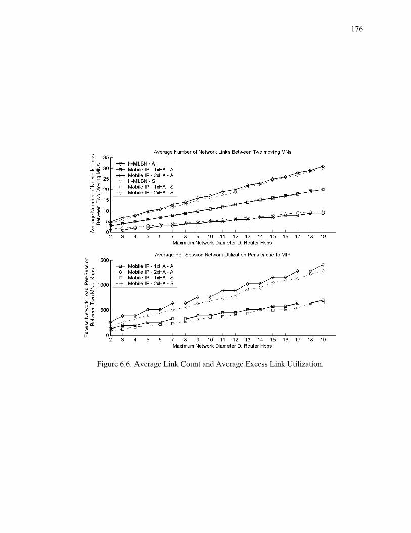
176
Figure 6.6. Average Link Count and Average Excess Link Utilization.

177
Figure 6.7. Average Aggregate Excess Network Utilization.
Figure 6.7 shows average aggregate excess network utilization due to the use of
Mobile IP and the associated triangular routing and bidirectional tunneling as defined in
Section 6.1.1.3. With the maximum network diameter of 19 router hops, the active life
utilization factor ½l = 0:5½l = 0:5 and other associated numerical parameters listed in Table 6.3,
the network carries on average approximately 100 Gbps excess traffic load due to
suboptimal routing.

178
The user facing penalty for triangular routing may be defined as increased delay
and jitter (delay variation), and increased packet loss probability caused by extra router
hops and network links on the path between the communicating MNs. As can be seen
from Figure 6.8, given the listed parameters, with a maximum network diameter of 10
hops the increase in one-way delay due to triangular routing for mobile-to-mobile
communication is approximately between 30 and 60 milliseconds (depending on the
number of serving HAs), along with the corresponding decrease in probability of
successful packet delivery between 3 - 5%.
Figure 6.8. Average Increase in Delay and Packet Loss Probability.

179
Figure 6.9. Hand-off Intensity ½h½h vs. Life-to-Mobility Ratio ½c½c.
Figure 6.9 provides comparison of the hand-off performance between H-MLBN
and MIP based schemes. As can be seen, for the very high mobility level (½c = 0:01½c = 0:01)
hand-off performance of both MIP based categories results in MNs spending on average
approximately 15% of their active lives during the hand-off procedures, compared with
4% for H-MLBN. For the high mobility level (½c = 0:1½c = 0:1) the situation is similar:
approximately 2% of active life is spent in hand-offs using MIP and 0.5% using H-
MLBN.

180
Figure 6.10 shows the update rates per type per mobility area. At the very high
and high mobility levels the predominant type of updates are the local events caused by
the cell boundary crossings internal to a Mobility Area. This figure also shows the MERS
level (the combined local, intra-area and inter-area update rate corresponding to ½c = 1½c = 1),
which is equal to 100 updates per unit time per Mobility Area.
Figure 6.10. Update Rates as a Function of LMR.

181
Figure 6.11 shows combined control plane message delivery cost as a function of
Life-to-Mobility Ratio for the three mobility management categories: H-MLBN, H-MIP
and B-MIP. Combined message delivery cost is defined as a sum of costs associated with
the network update event types (local, intra-area and inter-area) measured in
{hop £ message size£ event ratehop £ message size£ event rate}, where the average hop count between network
elements involved in the update process is determined by the network architecture, the
average message size is determined by the protocol and the event rates depend on the
mobility level. The costs and their differences are shown relative to the costs
corresponding to MERS. Overall the H-MLBN scheme shows best cost performance
across the mobility level range mostly due to the local update capability.
Similarly to Figure 6.11, Figure 6.12 shows the combined control plane message
processing costs of the three mobility management solution categories as a function of
the Life-to-Mobility Ratio. The message processing costs are measured in
{cpu instructions£ event ratecpu instructions£ event rate}, where CPU instructions depend on the cumulative
number of instructions required to process the network update message by all network
elements involved in the update and event rates depend on the mobility level. The
combined processing cost is defined as a sum of the processing costs associated with the
three network update types (local, intra-area and inter-area). As shown the H-MLBN
solution results in lowest control plane processing costs across the mobility level range
mostly due to the ability to perform low cost local update operations. Note that the
processing costs for the H-MIP schemes are higher than for the B-MIP schemes at high
mobility levels (0:01 · ½c < 0:10:01 · ½c < 0:1) due to the increased number of regional and area hand-

182
offs and the need to process updates at the FA, RFA and HA as compared to the FA and
HA for B-MIP.
Finally, Figure 6.13 shows the combined composite control plane messaging
costs. The combined composite cost is a sum of the message delivery and the message
processing costs. Overall H-MLBN produces the lowest control plane costs compared to
MIP.
Figure 6.11. Combined Control Plane Message Delivery Cost.

183
Figure 6.12. Combined Control Plane Message Processing Cost.

184
Figure 6.13. Combined Composite Control Plane Network Update Cost vs. LMR.

185
6.3. Chapter Summary
The analytical models derived in this chapter for device movements as well as for the
forwarding and control traffic delivery are independent from the mobility management
solution and were used to provide comparative analysis which demonstrated performance
improvements that can be achieved in H-MLBN over the Mobile IP based schemes both
in the area of forwarding plane traffic delivery and the control plane messaging.
The hierarchical architecture and specific methods of providing support for micro-
mobility in H-MLBN allow to control the cost of the network update messaging in such a
manner that the bulk of this cost shifts onto the locally executed procedures performed by
the edge nodes of the network. Specifically the local tracking of mobile devices by the H-
MLBN LERs enables to use a low cost update procedure for the most frequent type of
movement of mobile devices thus reducing the overall network update costs.
The forwarding plane performance evaluation of H-MLBN does not take into
account a transient period, equal to the time required to complete the Inter-Area Inter-
MSF network update, during which the routing of traffic between the communicating
mobile devices is temporarily sub-optimal (the traffic is routed via the old ALER until the
new ALER has been updated). This however is not expected to result in a noticeable
change in the forwarding plane performance of H-MLBN as the Inter-Area Inter-MSF
transitions are infrequent and the relative durations of the Inter-Area Inter-MSF hand-offs
are small compared to other hand-off types.
We specifically point out that the developed models capture only certain
important characteristics of the proposed system and its competitor systems in such a
manner as to allow for a reasonable comparative analysis specifically focused on

186
evaluating system behaviors as functions of their architectural structures and control
plane message flows. It is however clear that the comprehensive analysis of all aspects of
system performance and dynamics based on tractable analytical models may not be
feasible due to the involved complexities, and that such an analysis may be approached
through prototyping and actual system implementations.

187
CHAPTER 7. CONCLUSION
The Hierarchical Mobility Label Based Network (H-MLBN) presented in this thesis is a
novel network layer mobility management solution that may be described as independent
from Mobile IP all-MPLS macro- and micro-mobility management system that supports
for IPv6 and IPv4 mobile hosts and mobile routers under a common control and
forwarding plane while providing for optimal traffic routing. Extensive analysis of related
work shows that no existing proposals combine all of the above features in a single
solution.
7.1. Design Principals
In the development of H-MLBN we followed key design principals described in Section
1.2.
Integrated control and forwarding planes – H-MLBN provides native integration
between the MPLS-aware control plane and MPLS-based forwarding plane through the
use of the MP-BGP and MPLS label-stack forwarding. We use the term “native” with a
very specific meaning: in H-MLBN the operation of the control plane results in the
establishment of the concatenation of MPLS LSP segments on the path towards a mobile
node which in turn results in forwarding of the traffic using MPLS-level operations on
the intermediate network nodes (pop, push and swap). Moreover, the concatenation of the
LSP segments may be modified to reflect the movements of mobile nodes without
departure from the MPLS forwarding which is achieved through the use of Mobility
Labels. Lastly, the integration between the control and forwarding planes does not
involve a flow-driven MPLS LSP management following the movements of mobile

188
nodes. In contrast, a control plane mapping between a pre-established mesh of the
underlying LSPs and the logical location of mobile nodes (represented by Mobility
Labels) is used by distributing Mobility Bindings through a hierarchical and scalable
network update process. The main result of this integration is the ability to deliver mobile
traffic following the optimal end-to-end path in the network.
Robust and flexible control plane protocol framework – H-MLBN adopts a
distributed hierarchical control plane that does not involve all nodes in the network. Only
the intelligent edge nodes and certain aggregation nodes are aware of the mobility
management functions, which improves the scalability of the solution. This however is
done without a loss in the ability to deliver traffic in an optimal manner between the
communicating mobile devices. The structure of the protocol elements that carry the
mobility specific information is flexible enough and may be expanded to accommodate
new features in the future development.
Evolutionary architecture and implementation approach – H-MLBN architecture
builds on the existing well established internetworking architecture principals for
scalable, distributed and survivable network. This architecture is based on the network
regionalization and hierarchy that are proven to produce scalable and expandable
networks.
Efficient network responsiveness – H-MLBN regional architecture exploits the
fact that most of the mobile device movements are expected to be concentrated around a
given coverage area that may be served by a local network entity that is capable of
aggregating multiple radio and logical layer networks. Thus the hand-off procedures
proposed in H-MLBN shift the network update costs towards the most frequent

189
movement types that are handled by the least cost network update operations capable of
preserving traffic continuity between the communicating mobile nodes. At the same time
the segmented LSP model and the ability of the control plane to manipulate and distribute
the Mobility Binding information provide great flexibility in implementing efficient
traffic continuity procedures.
Acceptable network scalability and performance – In contrast to the existing
mobility management solutions that gravitate toward the use of centralized architectural
entities such as Home Agents H-MLBN presents a highly distributed architecture with
hierarchical control and forwarding planes that are natively integrated through the use of
MPLS. This approach results in improvements in both scalability and performance due to
the ability of the solution to distribute the control and forwarding plane processing loads
and avoid network “bottlenecks” associated with centralized designs.
7.2. Future Work
The evolution of cellular wireless communications involves advances in the areas of the
Radio Access and Packed Data communications. It has been a well recognized fact that
this evolution progresses towards packet based and specifically IP communications.
Recent development in the international standards organizations resulted in a
specification of the fourth generation (4G) wireless technologies collectively referred to
as the Long Term Evolution (LTE). One of the components of LTE and specifically its
Evolved Packet Core (EPC) is the network layer mobility management system.
It is important to highlight a certain disparity in the comparative advancements in
the areas of network layer mobility management and the radio access. At the radio level
the technology evolution made tremendous steps. Some of the examples specifically

190
relate to the packet data support such as Code Division Multiple Access (CDMA)
Evolution Data Optimized (EV-DO) and Global System for Mobile Communications
(GSM) High Speed Packet Access (HSPA) in 3G and Orthogonal Frequency Division
Multiplexing (OFDM) and Multiple Input Multiple Output (MIMO) in 4G, providing
higher speeds and lower latencies. However, as the packet data practically means IP
based communications a central issue remains the ability of the network technology to
efficiently support mobility at the network layer (IP).
From this perspective there has not been a significant change between the third
generation (3G) and the fourth generation (4G) technologies. In both cases the network
layer mobility management is based on the Mobile IP protocol or on the principals of
Mobile IP (GPRS Tunneling Protocol – GTP). In both technologies the client based
Mobile IP and the corresponding network components are used (in 3G a Packet Data
Serving Node/Foreign Agent – PDSN/FA and a Home Agent – HA; in 4G a Serving
Gateway – sGW and a Packet Data Network Gateway – pGW perform Mobile IP
functions). One difference between 3G and 4G is that 4G adopts a network based Mobile
IP in the form of Proxy Mobile IP.
Therefore we may point out an interesting developing paradox – as the evolution
from 3G to 4G offers higher data rates and lower latencies one may expect a significant
increase in the interest for mobile-to-mobile (or peer-to-peer) traffic patterns and
applications that are all based on IP. However, the underlying network layer mobility
management scheme employed in the network and based on Mobile IP is not optimized
for mobile-to-mobile communications and as shown in this thesis results in the user

191
facing as well as the network facing performance penalties that may be considered as
inhibiting factors in the network evolution.
On the other hand MPLS technology has been widely adopted in the IP transport
networks that support mobile traffic (such as IP networks of the wireless carriers). The
recent trends demonstrate a significant interest by the industry standards bodies and the
wireless carriers to introduce MPLS to the wireless access networks to perform functions
such as mobile traffic backhaul.
The continuation of work of this thesis is to contribute in the adoption of all-
MPLS based network layer mobility management schemes as part of the packet core
standards for the next generation wireless networks. As MPLS technology becomes part
of the Evolved Packet Core of the 4G network, the all-MPLS based network layer
mobility management may become part of the EPC functions supplementing and
eventually replacing Mobile IP.

192
List of References
1. O. Berzin, “Mobility Label Based Network: Mobility Support in Label Switched Networks with Multi-ProtocolBGP,” Journal of Computer Networks (COMNET), Vol. 52, Issue 9, Jun. 2008, Page(s): 1732-1744.
2. O. Berzin, “Mobility Label Based Network: Hierarchical Mobility Management and Packet Forwarding Architecture,” Journal of Computer Networks (COMNET), Vol. 53, Issue 12, Aug. 2009, Page(s): 2153-2181.
3. O. Berzin, A. Malis, “Mobility Support Using MPLS and MP-BGP Signaling”, Internet Draft (work in progress), October 2007.
4. Perkins, “IP Mobility Support for IPv4”, Request for Comment 3344, August 2002.
5. Rosen, Y. Rekhter, “BGP/MPLS VPNs”, Request for Comment 4364, February 2006.
6. J. Schiller, “Mobile Communications”, Second Edition, Addison-Wesley, 2003.
7. Y. Rekhter, E. Rosen, “Carrying Label Information in BGP-4,” Request for Comment 3107, May 2001.
8. T. Bates et al., “Multiprotocol Extensions for BGP-4,” Request for Comment 4760, January 2007.
9. G. Valko, "Cellular IP - A New Approach to Internet Host Mobility," ACM Computer Communication Review, January 1999.
10. E. Rosen et al., “Multiprotocol Label Switching Architecture”, Request for Comment 3031, January 2001.
11. Johnson, D., Perkins, C., and J. Arkko, "Mobility Support in IPv6", Request for Comment 3775, June 2004.
12. F. M. Chiussi, D. A. Khotimsky, and S. Krishnan, "Mobility management in third-generation all-IP networks," IEEE Commun. Mag., pp. 124-135, Sep. 2002.
13. T. Yang, Y. Dong, Y. Zhang, and D. Makrakis, "Practical approaches for supporting micro mobility with MPLS," in IEEE ICT, 2002.
14. K. Xie, V.Wong, and V. Leung, "Support of micro-mobility in MPLS based wireless access networks," in Proc. IEEE WCNC,Mar. 2003, vol. 2, pp. 1242-1247.

193
15. V. Vassiliou, H. L. Owen, D. Barlow, J. Sokol, H.-P. Huth, and J. Grimminger, "M-MPLS: Micromobility-enabled multiprotocol label switching," in Proc. IEEE ICC, 2003, vol. 1, pp. 250-255.
16. R. Langar, S. Tohme, and N. Bouabdallah, "Mobility management support and performance analysis for wireless MPLS networks," ACMWiley Int. J. Netw. Manag., vol. 16, no. 4, pp. 279-294, Jul. 2006.
17. R. Langar, N. Bouabdallah, R. Boutaba, ”A comprehensive analysis of mobility management in MPLS-based wireless access networks,” IEEE/ACM Transactions on Networking, vol. 16, no 4, Aug. 2008.
18. Perkins, D. B. Johnson, “Route Optimization in Mobile IP,” Internet draft, draft-ietf-mobileip-optim-11.txt, Sep. 2001.
19. K. Leung at al., “Network Mobility (NEMO) Extensions for Mobile IPv4”, Request for Comment 5177, April 2008.
20. Devarapalli, V., Wakikawa, R., Petrescu, A., and P. Thubert, "Network Mobility (NEMO) Basic Support Protocol", Request for Comment 3963, January 2005.
21. E. Gustafson, A. Johnson, C. Perkins, “Mobile IP regional Registration,” Internet draft, draft-ietf-mobileip-reg-tunnel-09.txt, June 2004.
22. Soliman et al., ”Hierarchical MIPv6 Mobility Management,” RFC 4140, Aug. 2005.
23. Chiussi, F.A.; Khotimsky, D.A.; Krishnan, S., “A network architecture for MPLS-based micro-mobility,” Wireless Communications and Networking Conference, 2002. WCNC2002. 2002 IEEE, Volume: 2 Mar 2002, Page(s): 549- 555 vol.2
24. K. El Malki, “Low-Latency Handoffs in Mobile IPv4,” Request for Comment 4881, June 2007.
25. R. Koodli, “Fast Handovers for Mobile IPv6,” Request for Comment 4068, July 2005.
26. S. Gundavelli et al., “Proxy Mobile IPv6”, Request for Comment 5213, August 2008.
27. R. Ramaswamy, N. Weng, T. Wolf, “Considering processing cost in network simulations,” ACM SIGCOM Workshops, Aug. 2003.
28. Y. Lin, “Reducing location update cost in a PCS network,” IEEE/ACM Transactions on Networking, vol. 5, no. 1, Feb 1997.
29. R. Braden et al., “Resource ReSerVation Protocol (RSVP),” Request for Comment 2205, Sep. 1997.
30. L. Anderson et. al., “LDP Specification,” Request for Comment 3036, Jan. 2001.

194
31. C. Bettstetter, G. Resta, P. Santi, ”The Node Distribution of the Random Waypoint Mobility Model for Wireless Ad Hoc Networks,” IEEE Transactions on Mobile Computing, Vol. 2, No. 3, Jul.-Sep. 2003.
32. E. Hyytia, J. Virtamo, “Random Waypoint Mobility Model in Cellular Networks,” Wireless Networks, Vol. 13, Issue 2, Apr. 2007, Page(s): 177-188.

195
APPENDIX A. PROTOCOL ELEMENTS AND MESSAGE FORMATS
A.1. Mobility Support Function
A.1.1. Mobile Node Discovery, Registration and Status
A.1.1.1. Discovery Process - IPv4
As in RFC 3344 the discovery of the MSF by the mobile nodes is based on the
ICMP Router Discovery RFC 1256 with specific extensions for Mobility Label Based
Network (MLBN). The format of the extensions used in this proposal also follows the
RFC 3344 section 1.9. The discovery process should be initiated by a mobile host or
router by sending the ICMP Router Solicitation message with MLBN MSF Discovery
Extension and the TTL set to 1. This ICMP message along with the MLBN Extension is
referred to as the MSF Discovery message. The MSF Discovery message should carry the
information about the type of the mobile node: Mobile Host or Mobile Router. Upon
receipt of the MSF Discovery message the MSF LER must respond with the ICMP
Router Advertisement including the MLBN specific Extension. This message is referred
to as the MSF Advertisement. The MSF Advertisement will carry different information
depending on the type of the mobile node and the registration mode.
0 1 2 3 0 1 2 3 4 5 6 7 8 9 0 1 2 3 4 5 6 7 8 9 0 1 2 3 4 5 6 7 8 9 0 1 +-+-+-+-+-+-+-+-+-+-+-+-+-+-+-+-+-+-+-+-+-+-+-+-+-+-+-+-+-+-+-+-+ | Type | Code | Checksum | +-+-+-+-+-+-+-+-+-+-+-+-+-+-+-+-+-+-+-+-+-+-+-+-+-+-+-+-+-+-+-+-+ | Reserved | +-+-+-+-+-+-+-+-+-+-+-+-+-+-+-+-+-+-+-+-+-+-+-+-+-+-+-+-+-+-+-+-+ | MSF Discovery Extension TLV (variable) | +-+-+-+-+-+-+-+-+-+-+-+-+-+-+-+-+-+-+-+-+-+-+-+-+-+-+-+-+-+-+-+-+
Figure A.1. ICMP Router Solicitation with MSF Discovery Extension

196
Figure A.1 shows the message format for the ICMP Router Solicitation carrying
the MSF Discovery Extension. The message fields are defined as follows:
Link Layer Fields: Destination Address - This should be the multicast or
broadcast Link Layer Address.
IP Fields: Source Address - IP Address of the Mobile Host or IP address of the
interface of the Mobile Router from which this message is sent. Destination Address -
This is the all-routers multicast address 224.0.0.2 or the limited broadcast address
255.255.255.255.
TTL - TTL should be set to 1.
ICMP Fields: Type = 10 Router Solicitation. Code = 1 MLBN MSF Discovery
Extension included.
0 1 2 3 0 1 2 3 4 5 6 7 8 9 0 1 2 3 4 5 6 7 8 9 0 1 2 3 4 5 6 7 8 9 0 1 +-+-+-+-+-+-+-+-+-+-+-+-+-+-+-+-+-+-+-+-+-+-+-+-+-+-+-+-+-+-+-+-+ | Type | Code | Checksum | +-+-+-+-+-+-+-+-+-+-+-+-+-+-+-+-+-+-+-+-+-+-+-+-+-+-+-+-+-+-+-+-+ | Num Addrs |Addr Entry Size| Lifetime | +-+-+-+-+-+-+-+-+-+-+-+-+-+-+-+-+-+-+-+-+-+-+-+-+-+-+-+-+-+-+-+-+ | Router Address[1] | +-+-+-+-+-+-+-+-+-+-+-+-+-+-+-+-+-+-+-+-+-+-+-+-+-+-+-+-+-+-+-+-+ | Preference Level[1] | +-+-+-+-+-+-+-+-+-+-+-+-+-+-+-+-+-+-+-+-+-+-+-+-+-+-+-+-+-+-+-+-+ | MSF Advertisement Extension (variable) | +-+-+-+-+-+-+-+-+-+-+-+-+-+-+-+-+-+-+-+-+-+-+-+-+-+-+-+-+-+-+-+-+
Figure A.2. ICMP Router Advertisement with MSF Advertisement Extension
Figure A.2 shows the message format for the ICMP Router Advertisement
carrying the MSF Advertisement Extension. The message fields are defined as follows:
Link Layer Fields: Destination Address - This should be the source address used
to deliver the MSF Discovery message from the mobile node.

197
IP Fields: Source Address - IP Address of the MSF. Destination Address - This
is the unicast IP address used in the IP header of the MSF Discovery message from the
mobile node.
TTL - TTL should be set to 1.
ICMP Fields: Type = 9 Router Advertisement. Code = 1 MLBN MSF
Advertisement Extension included. Please refer to RFC 1256 for the specification of the
remaining fields in both of the above messages.
A.1.1.2. MSF Discovery by Mobile Hosts - IPv4
Mobile hosts should initiate the MSF Discovery process by sending the MSF Discovery
message. The MSF Discovery Extension format for Mobile Hosts is shown in Figure
A.3.
0 1 2 3 0 1 2 3 4 5 6 7 8 9 0 1 2 3 4 5 6 7 8 9 0 1 2 3 4 5 6 7 8 9 0 1 +-+-+-+-+-+-+-+-+-+-+-+-+-+-+-+-+-+-+-+-+-+-+-+-+-+-+-+-+-+-+-+-+ | Type | Length |H| Pri.|L|ASTI | Area_ID | +-+-+-+-+-+-+-+-+-+-+-+-+-+-+-+-+-+-+-+-+-+-+-+-+-+-+-+-+-+-+-+-+ | Mobile Host IPv4 Source Address | +-+-+-+-+-+-+-+-+-+-+-+-+-+-+-+-+-+-+-+-+-+-+-+-+-+-+-+-+-+-+-+-+ | Correlation ID | +-+-+-+-+-+-+-+-+-+-+-+-+-+-+-+-+-+-+-+-+-+-+-+-+-+-+-+-+-+-+-+-+
Figure A.3. Mobile Host MSF Discovery Extension for IPv4
Type 0 = MSF Discovery
Length - Length of the message in octets.
H - Mobile Node Type Indication. 0 = Mobile Host.
Pri. - A 3-bit Priority Code (0-7).
L - Lightweight Registration Requested (1).

198
ASTI - Application Service Type Indication. This 3-bit field may be used to
indicate to the MSF what type of service is to be used by the mobile host. For example,
"Internet Access Only" or Full Mobile-to-Mobile Routing". This indication can then be
mapped to the Network Update Mode Code used in the Mobility Binding structure.
Area_ID - An Identifier (1-255) associated with the Area Mobility Route
Reflector. Area_ID=0 must be used for initial registrations by mobile nodes.
Correlation ID - a number used to keep track of the Lightweight Registration
message pairs - MSF Discovery/MSF Advertisement.
A.1.1.3. MSF Discovery by Mobile Routers - IPv4
Mobile routers should initiate the MSF Discovery process by sending the MSF Discovery
message. The MSF Discovery Extension format for Mobile Routers is shown in Figure
A.4.
0 1 2 3 0 1 2 3 4 5 6 7 8 9 0 1 2 3 4 5 6 7 8 9 0 1 2 3 4 5 6 7 8 9 0 1 +-+-+-+-+-+-+-+-+-+-+-+-+-+-+-+-+-+-+-+-+-+-+-+-+-+-+-+-+-+-+-+-+ | Type | Length |R|Pri. |L|Res. | Area_ID | +-+-+-+-+-+-+-+-+-+-+-+-+-+-+-+-+-+-+-+-+-+-+-+-+-+-+-+-+-+-+-+-+ | Mobile IPv4 Router-ID | +-+-+-+-+-+-+-+-+-+-+-+-+-+-+-+-+-+-+-+-+-+-+-+-+-+-+-+-+-+-+-+-+
Figure A.4. Mobile Router MSF Discovery Extension
Type - 0 = MSF Discovery
Length - Length of the message in octets.
R - Mobile Node Type Indication. 1 = Mobile Router.
Pri. - A 3-bit Priority Code (0-7).
L - Always set to 0 in the MSF Discovery sent by a mobile router.
Res. - Reserved.

199
Area_ID - An Identifier (1-255) associated with the Area Mobility
Route Reflector. Area_ID=0 must be used for initial registrations by mobile
nodes.
A.1.1.4. MSF Advertisement - IPv4
After receiving the MSF Discovery message from a mobile host or router the MSF should
reply with the MSF Advertisement message using extension format is shown in Figure
A.5.
0 1 2 3 0 1 2 3 4 5 6 7 8 9 0 1 2 3 4 5 6 7 8 9 0 1 2 3 4 5 6 7 8 9 0 1 +-+-+-+-+-+-+-+-+-+-+-+-+-+-+-+-+-+-+-+-+-+-+-+-+-+-+-+-+-+-+-+-+ | Type | Length | Sequence Number | +-+-+-+-+-+-+-+-+-+-+-+-+-+-+-+-+-+-+-+-+-+-+-+-+-+-+-+-+-+-+-+-+ | Registration Lifetime |L|R|G|Reserved | Group ID | +-+-+-+-+-+-+-+-+-+-+-+-+-+-+-+-+-+-+-+-+-+-+-+-+-+-+-+-+-+-+-+-+ | MSF IP Address | +-+-+-+-+-+-+-+-+-+-+-+-+-+-+-+-+-+-+-+-+-+-+-+-+-+-+-+-+-+-+-+-+ | MSF Virtual Link Layer Address (first 32 bits) | +-+-+-+-+-+-+-+-+-+-+-+-+-+-+-+-+-+-+-+-+-+-+-+-+-+-+-+-+-+-+-+-+ |Last 16 bits | Reserved | Area_ID | +-+-+-+-+-+-+-+-+-+-+-+-+-+-+-+-+-+-+-+-+-+-+-+-+-+-+-+-+-+-+-+-+ | Correlation ID | +-+-+-+-+-+-+-+-+-+-+-+-+-+-+-+-+-+-+-+-+-+-+-+-+-+-+-+-+-+-+-+-+
Figure A.5. MSF Advertisement Extension
Type - 1 = MSF Advertisement
Length - Length of the message in octets.
Sequence Number - The sequence number of the MSF Advertisement message
sent since the MSF is operational.
Registration Lifetime - the time in seconds until the registration entry in the MSF
database expires.
L - Lightweight Registration Confirmed (1).
R - Full Registration Required (1).

200
G - Group Registration Supported (1).
Group ID - Unique Registration Group Number. Should be zero if G = 0
MSF IP Address - Virtual IP Address of the MSF (may be different from any
particular MSF LER interface IP address
MSF Virtual Link Layer Address - a MAC address shared and recognized by all
MPLS LER interfaces participating in the MSF.
Area_ID - An Identifier (1-255) associated with the Area Mobility Route
Reflector. Area_ID=0 must be used for initial registrations by mobile nodes.
Correlation ID - a number used to keep track of the registration requests and the
corresponding reply message pairs.
A.1.2. Discovery Process - IPv6
The MSF discovery process for IPv6 is identical to the discovery process for IPv4 with
the exception of the use of IPv6 specific Router Solicitation and Advertisement messages
based on ICMPv6 [RFC4443]. These messages are specified in [RFC4861]. As in the
IPv4 case the Router Solicitation and Advertisement messages carry the MLBN
extensions and are termed the MSF Discovery and the MSF Advertisement respectively.
A.1.3. Registration and Status - IPv4
A.1.3.1. Mobile Host Registration - IPv4
Lightweight Registration - IPv4
MLBN eliminates the need for the registrations with the Home Agent and Care-of-
Addresses. This makes it possible to implement a Lightweight Registration procedure
which is simply the completion of the MSF Discovery process. The Lightweight

201
Registration is indicated by the presence of the L flag in the MSF Advertisement
message. With the Lightweight Registration the MSF should allocate the local Mobility
Label and create the Mobility Binding structure immediately following the receipt of the
MSF Discovery message from a mobile host. The MSF should also initiate the network
update process based on the selected update mode and the indicated mobile application
priority.
Full Registration - IPv4
Full Registration is a registration mode which allows to perform additional functions as
part of the registration process. An example of such function is the Mobile Host
Authentication. Full registration mode is indicated in the MSF Advertisement by setting
the R flag. Full Registration uses two message types:
Registration Request - Type 1
Registration Reply - Type 2
The Registration Message formats are shown in Figure A.6.
0 1 2 3 0 1 2 3 4 5 6 7 8 9 0 1 2 3 4 5 6 7 8 9 0 1 2 3 4 5 6 7 8 9 0 1 +-+-+-+-+-+-+-+-+-+-+-+-+-+-+-+-+-+-+-+-+-+-+-+-+-+-+-+-+-+-+-+-+ | Type | Length |H| Rri.|ASTI | Area_ID | +-+-+-+-+-+-+-+-+-+-+-+-+-+-+-+-+-+-+-+-+-+-+-+-+-+-+-+-+-+-+-+-+ | Mobile Host IPv4 Source Address | +-+-+-+-+-+-+-+-+-+-+-+-+-+-+-+-+-+-+-+-+-+-+-+-+-+-+-+-+-+-+-+-+ | MSF Address | +-+-+-+-+-+-+-+-+-+-+-+-+-+-+-+-+-+-+-+-+-+-+-+-+-+-+-+-+-+-+-+-+ | Correlation ID | +-+-+-+-+-+-+-+-+-+-+-+-+-+-+-+-+-+-+-+-+-+-+-+-+-+-+-+-+-+-+-+-+ | Extensions +-+-+-+-+-+-+....
Figure A.6. Full Registration Request

202
Type - 1 = Full Registration Request
Length - Length of the message in octets.
H - Mobile Node Type Indication. 0 = Mobile Host
Pri. - A 3-bit priority code (0-7).
ASTI - Application Service Type Indication.
Area_ID - An Identifier (1-255) associated with the Area Mobility Route
Reflector. Area_ID=0 must be used for initial registrations by mobile nodes.
Correlation ID - a number used to keep track of the registration requests and the
corresponding reply message pairs.
Figure A.7. shows a Full Registration Reply message format.
0 1 2 3 0 1 2 3 4 5 6 7 8 9 0 1 2 3 4 5 6 7 8 9 0 1 2 3 4 5 6 7 8 9 0 1 +-+-+-+-+-+-+-+-+-+-+-+-+-+-+-+-+-+-+-+-+-+-+-+-+-+-+-+-+-+-+-+-+ | Type | Length | Flags | +-+-+-+-+-+-+-+-+-+-+-+-+-+-+-+-+-+-+-+-+-+-+-+-+-+-+-+-+-+-+-+-+ | Registration Lifetime | Reserved | Area_ID | +-+-+-+-+-+-+-+-+-+-+-+-+-+-+-+-+-+-+-+-+-+-+-+-+-+-+-+-+-+-+-+-+ | Mobile Host IPv4 Source Address | +-+-+-+-+-+-+-+-+-+-+-+-+-+-+-+-+-+-+-+-+-+-+-+-+-+-+-+-+-+-+-+-+ | MSF IP Address | +-+-+-+-+-+-+-+-+-+-+-+-+-+-+-+-+-+-+-+-+-+-+-+-+-+-+-+-+-+-+-+-+ | MSF Virtual Link Layer Address (first 32 bits) | +-+-+-+-+-+-+-+-+-+-+-+-+-+-+-+-+-+-+-+-+-+-+-+-+-+-+-+-+-+-+-+-+ |Last 16 bits | Reserved | +-+-+-+-+-+-+-+-+-+-+-+-+-+-+-+-+-+-+-+-+-+-+-+-+-+-+-+-+-+-+-+-+ | Correlation ID | +-+-+-+-+-+-+-+-+-+-+-+-+-+-+-+-+-+-+-+-+-+-+-+-+-+-+-+-+-+-+-+-+ | Extensions +-+-+-+-+-+-+....
Figure A.7. Full Registration Reply
Type - 2 = Full Registration Reply
Length - Length of the message in octets.
Registration Lifetime - the time in seconds until the registration entry in the MSF
database expires.

203
Area_ID - An Identifier (1-255) associated with the Area Mobility Route
Reflector. Area_ID=0 must be used for initial registrations by mobile nodes.
MSF IP Address - Virtual IP Address of the MSF (may be different from any
particular MSF LER interface IP address
MSF Virtual Link Layer Address - a MAC address shared and recognized by all
MPLS LER interfaces participating in the MSF.
Correlation ID - a number used to keep track of the registration requests and the
corresponding reply message pairs.
A.1.3.2. Mobile Router Registration - IPv4
Mobile routers should initiate the registration procedure by sending the registration
message with the mobile router identification flag set and its Router ID (an IP address
that belongs to the router) specified. Upon receipt of this registration information the
MSF should initiate the establishment of the dynamic routing protocol adjacency with the
mobile router. The mobile router should advertise to the MSF the IP prefixes it serves
using the established routing adjacency.
The MSF should receive the routing protocol update from the mobile router and
allocate a single Mobility Label to represent all of the served prefixes. This label should
then be used in the Mobility Binding structure exported to the network by MP-BGP.
Optionally, each served IP prefix advertised by the mobile router can be associated with a
separate Mobility Label. This can be used to provide different mobility processing
priority to different IP prefixes. The mobile router status detection can be based on the
state of the dynamic routing protocol adjacency maintained by the periodic keepalive
messaging common to the routing protocols.

204
Explicit Prefix Registration
In some cases it is not desirable to establish a dynamic routing protocol adjacency
between a mobile router and the MSF LER due to the considerations related to the
conservation of RAN resources required to support the maintenance of the adjacency
(e.g. periodic "hello" packets).
An alternative method of enabling a mobile router to register it's locally attached
sub-nets or prefixes is to include the prefix/length information in the MSF registration
messages. The Explicit Prefix Registration message should be sent by a mobile router in
response to the MSF Advertisement message it receives following the initial MSF
Discovery. The Explicit Prefix Registration message structure is shown in Figure A.8.
0 1 2 3 0 1 2 3 4 5 6 7 8 9 0 1 2 3 4 5 6 7 8 9 0 1 2 3 4 5 6 7 8 9 0 1 +-+-+-+-+-+-+-+-+-+-+-+-+-+-+-+-+-+-+-+-+-+-+-+-+-+-+-+-+-+-+-+-+ | Type | Length |R|Pri. |L|Res. | Area_ID | +-+-+-+-+-+-+-+-+-+-+-+-+-+-+-+-+-+-+-+-+-+-+-+-+-+-+-+-+-+-+-+-+ | Mobile IPv4 Router-ID | +-+-+-+-+-+-+-+-+-+-+-+-+-+-+-+-+-+-+-+-+-+-+-+-+-+-+-+-+-+-+-+-+ | Sub-Type | Pref. Length | Prefix | +-+-+-+-+-+-+-+-+-+-+-+-+-+-+-+-+-+-+-+-+-+-+-+-+-+-+-+-+-+-+-+-+ | Prefix | +-+-+-+-+-+-+-+-+-+-+-+-+-+-+-+-+...
Figure A.8. Mobile Router Explicit Prefix Registration Message
Type - 0 = MSF Discovery
Length - Length of the message in octets.
R - Mobile Node Type Indication. 1 = Mobile Router.
Pri. - A 3-bit Priority Code (0-7).
L - Always set to 0 in the MSF Discovery sent by a mobile router.

205
Res. - Reserved.
Area_ID - An Identifier (1-255) associated with the Area Mobility Route
Reflector. Area_ID=0 must be used for initial registrations by mobile nodes.
Sub-Type - 0 = Prefix Registration, 1 = Prefix De-registration.
Pref. Length - Prefix Length.
Prefix - Prefix Value.
The MSF receiving the Explicit Prefix Registration from a mobile router should
extract the prefix/length information from the received message and associate it with the
mobile router ID in the registration record. In addition the MSF should use the received
prefix/length information in the router mobility binding.
A.1.4. Registration and Status - IPv6
The registration procedures described for IPv4 are fully extended to IPv6 using the same
message formats. In all messages the IPv4 addresses are replaced with their IPv6
equivalents (with the corresponding increase in the required field length).
A.2. Integration with MP-BGP
In order to integrate the MSF on the LER with the MP-BGP processing, a new Address
Family must be created. This Address Family must be assigned a new and unique AFI
following the Address Family structure of MP-BGP. This Address Family may be
referred to as the Mobility Address Family. In fact a number of Mobility Address
Families may be created to support IPv4/IPv6 unicast/multicast protocols. In all cases
the Address Families must use the structure that allows them to carry the overlay MPLS
label information.

206
A.2.1. Mobility Address Family
In order to carry the Mobility Binding information the BGP UPDATE message with the
MP_REACH_NLRI and MP_UNREACH_NLRI optional non-transitive attributes is
used as specified in [RFC4760]. For the mobility management purposes a set of new
Address Family Identifiers (AFI) and Subsequent Address Family Identifiers (SAFI) are
defined. Specifically the following new AFI values are defined: Mobility IPv4 Unicast
and Mobility IPv6 Unicast. The MP_REACH_NLRI attribute is used to update the LER
nodes with new Mobility Binding information. The structure of the attribute is shown in
Figure A.9.
+---------------------------------------------------------+ | Address Family Identifier (2 octets) | +---------------------------------------------------------+ | Subsequent Address Family Identifier (1 octet) | +---------------------------------------------------------+ | Length of Next Hop Network Address (1 octet) | +---------------------------------------------------------+ | Network Address of Next Hop (variable) | +---------------------------------------------------------+ | Reserved (1 octet) | +---------------------------------------------------------+ | Mobility Binding (NLRI) Information (variable) | +---------------------------------------------------------+
Figure A.9. MP_REACH_NLRI with Mobility Binding
The MP_UNREACH_NLRI attribute is used to withdraw the Mobility Binding
information. The structure of the attribute is shown in Figure A.10.

207
+---------------------------------------------------------+ | Address Family Identifier (2 octets) | +---------------------------------------------------------+ | Subsequent Address Family Identifier (1 octet) | +---------------------------------------------------------+ | Mobility Binding (Withdrawn Routes) (variable) | +---------------------------------------------------------+
Figure A.10. MP_UNREACH_NLRI with Mobility Binding
The Mobility Binding itself is encoded in the NLRI format shown in Figure A.11.
+---------------------------+ | Length (1 octet) | +---------------------------+ |Mobility Binding (variable)| +---------------------------+
Figure A.11. NLRI Encoding for Mobility Bindings
For the definitions of the fields in the above figures (with the exception of the
Mobility Binding related information) please see [RFC4760].
A.2.2. Mobility Bindings
Two types of Mobility Binding formats are proposed: Host Mobility Binding and Router
Mobility Binding. The encoding formats are shown in Figures A.12 and A.13
respectively.

208
0 1 2 3 0 1 2 3 4 5 6 7 8 9 0 1 2 3 4 5 6 7 8 9 0 1 2 3 4 5 6 7 8 9 0 1 +-+-+-+-+-+-+-+-+-+-+-+-+-+-+-+-+-+-+-+-+-+-+-+-+-+-+-+-+-+-+-+-+ | Origin MP-BGP NEXT_HOP | +-+-+-+-+-+-+-+-+-+-+-+-+-+-+-+-+-+-+-+-+-+-+-+-+-+-+-+-+-+-+-+-+ | Target MP-BGP NEXT_HOP | +-+-+-+-+-+-+-+-+-+-+-+-+-+-+-+-+-+-+-+-+-+-+-+-+-+-+-+-+-+-+-+-+ | Mobile Host Address | +-+-+-+-+-+-+-+-+-+-+-+-+-+-+-+-+-+-+-+-+-+-+-+-+-+-+-+-+-+-+-+-+ |H| UM | UT | Mobility Label |Pri. |S| +-+-+-+-+-+-+-+-+-+-+-+-+-+-+-+-+-+-+-+-+-+-+-+-+-+-+-+-+-+-+-+-+ | Area_ID | +-+-+-+-+-+-+-+-+
Figure A.12. NLRI Encoding for the Host Mobility Binding
Origin MP-BGP NEXT_HOP - Router ID of the MPLS LER originating the
Mobility Binding. This address may be carried in the IPv4 or IPv6 format depending on
the {AFI, SAFI} pair used.
Target MP-BGP NEXT_HOP - Router ID of the MPLS LER to receive the
Mobility Binding using Selective Downstream Push. For the Unsolicited Downstream
Push this field should be set to 0. This address may be carried in the IPv4 or IPv6 format
depending on the {AFI, SAFI} pair used.
Mobile Host Address - IPv4 or IPv6 Address of the mobile host. This address
may be carried in the IPv4 or IPv6 format depending on the {AFI, SAFI} pair used.
H - Mobile Node Type Indication. 0 = Mobile Host
UM - Update Mode. This 3-bit is used to indicate the Network Update Mode
selection.
UT - Update Type. This 4-bit code is used to indicate the Mobility Update Type
(internal, external, inter-carrier).

209
Mobility Label - Overlay MPLS Label (20 bits) associated with the IP address of
the mobile host in the MSF database.
Pri. - A 3-bit priority code (0-7).
S - Bottom of Stack.
Area_ID - An Identifier (1-255) associated with the Area Mobility Route
Reflector.
0 1 2 3 0 1 2 3 4 5 6 7 8 9 0 1 2 3 4 5 6 7 8 9 0 1 2 3 4 5 6 7 8 9 0 1 +-+-+-+-+-+-+-+-+-+-+-+-+-+-+-+-+-+-+-+-+-+-+-+-+-+-+-+-+-+-+-+-+ | Origin MP-BGP NEXT_HOP | +-+-+-+-+-+-+-+-+-+-+-+-+-+-+-+-+-+-+-+-+-+-+-+-+-+-+-+-+-+-+-+-+ | Target MP-BGP NEXT_HOP | +-+-+-+-+-+-+-+-+-+-+-+-+-+-+-+-+-+-+-+-+-+-+-+-+-+-+-+-+-+-+-+-+ | Mobile Router ID | +-+-+-+-+-+-+-+-+-+-+-+-+-+-+-+-+-+-+-+-+-+-+-+-+-+-+-+-+-+-+-+-+ |R| UM | UT |No of Prefixes | IP Prefix 1 | +-+-+-+-+-+-+-+-+-+-+-+-+-+-+-+-+-+-+-+-+-+-+-+-+-+-+-+-+-+-+-+-+ | IP Prefix 1 | Prefix 1 Len. | Variable No. | +-+-+-+-+-+-+-+-+-+-+-+-+-+-+-+-+-+-+-+-+-+-+-+-+-+-+-+-+-+-+-+-+ | of Prefixes/Len | +-+-+-+-+-+-+-+-+-+-+-+-+-+-+-+-+-+-+-+-+-+-+-+-+-+-+-+-+-+-+-+-+ | Mobility Label |Pri. |S| Area_ID | +-+-+-+-+-+-+-+-+-+-+-+-+-+-+-+-+-+-+-+-+-+-+-+-+-+-+-+-+-+-+-+-+
Figure A.13. NLRI Encoding for the Router Mobility Binding
Origin MP-BGP NEXT_HOP - Router ID of the MPLS LER originating the
Mobility Binding. This address may be carried in the IPv4 or IPv6 format depending on
the {AFI, SAFI} pair used.
Target MP-BGP NEXT_HOP - Router ID of the MPLS LER to receive the
Mobility Binding using Selective Downstream Push. For the Unsolicited Downstream
Push this field should be set to 0. This address may be carried in the IPv4 or IPv6 format
depending on the {AFI, SAFI} pair used.

210
Mobile Router ID - IP Address of the mobile router. This address may be carried
in the IPv4 or IPv6 format depending on the {AFI, SAFI} pair used.
R - Mobile Node Type Indication. 1 = Mobile Router
UM - Update Type. This 3-bit code is mapped to the ASTI code in the MSF
Discovery and Registration Request messages to indicate the Network Update Mode
selection.
UT - Update Type. This 4-bit code is used to indicate the Mobility Update Type
(internal, external, inter-carrier).
No. of Prefixes - Number of IP Prefixes carried in this Mobility Binding.
IP Prefix 1 - First IP Prefix (32 bits for IPv4, 128 bits for IPv6)
Prefix 1 Len. - Length (in number of bits) of the network part of IP Prefix 1
Mobility Label - Overlay MPLS Label (20 bits) associated with each of the IP
Prefixes served by the mobile router in the MSF database of the originating LER.
S - Bottom of Stack.
Area_ID - An Identifier (1-255) associated with the Area Mobility Route
Reflector.
The receiving MSF must read the R flag in the Mobility Binding and associate the
provided Mobility Label with each of the IP prefixes found in the body of the Mobility
Binding. The derived associations must be installed in the MPLS forwarding table of the
MPLS LER and in turn associated with the infrastructure label assigned to the "Origin
MP-BGP NEXT_HOP" address indicated in the received Mobility Binding

211
A.3. Network Update Modes and Types
The following four modes for the Mobility Binding Distribution or Withdrawal are
proposed: i) unsolicited downstream push, ii) selective downstream push, iii) hierarchical
on-demand distribution.
A.3.1. Unsolicited Downstream Push Mode
In this mode the originating LER node updates all other MSF enabled LER nodes that are
directly peered with it. In case of a hierarchical topology the originating LER node sends
a MP-BGP update with the Mobility Binding information to a Route Reflector which in
turn updates all of the participating MSF enabled LER Route Reflector clients. The
Update Mode Code for this mode is binary 000.
A.3.2. Selective Downstream Push Mode
In this mode the Mobility Binding updates are only sent to a select set of the MSF
enabled LER nodes. The Update Type Mode for this mode is binary 001.
A.3.3. Hierarchical On-Demand Distribution Mode
The Mobility Binding update is first sent by a serving MSF LER to a set of Mobility
Route Reflectors using the Selective Downstream Push. Once the Mobility Route
Reflectors have been updated, all other LER nodes must explicitly request Mobility
Labels from the Mobility Route Reflectors for packets destined to a mobile node. The
Update Mode Code for this mode is binary 011.

212
A.3.3.1. On-Demand Requests for Mobility Binding Information
To support the Hierarchical On-Demand Distribution Network Update Mode the
following explicit Mobility Binding information request procedure based on MP-BGP
may be used. When a MPLS LER supporting MPLS Mobility receives an IP packet, it
first should check if the Destination Address listed in the IP header belongs to the overall
IP address range assigned to the mobility functions and the corresponding mobile device
fleet. If the Destination Address falls within this range and the matching Mobility
Binding is present in the LER MSF database, the packet should be encapsulated using the
appropriate MPLS label stack and forwarded on the LSP toward the LER that is listed as
the "Origin MP-BGP NEXT_HOP" in the Mobility Binding. If the IP address is outside
of the mobility fleet range the packet must be treated in accordance with the conventional
rules based on either the IP or MPLS forwarding tables.
If the packet falls into the mobility fleet range and no matching Mobility Binding
entry exists in the MSF database, the LER should send an on-demand request for
Mobility Binding Information to the designated Mobility Route Reflector. This request is
encoded as a special type of the MP_REACH_NLRI attribute using a specific SAFI
value and one of the AFI values defined earlier. The Mobility Route Reflector should
process the request and return the Mobility Binding update to the requesting LER. The
NLRI encoding is shown in Figure A.14.

213
0 1 2 3 0 1 2 3 4 5 6 7 8 9 0 1 2 3 4 5 6 7 8 9 0 1 2 3 4 5 6 7 8 9 0 1 +-+-+-+-+-+-+-+-+-+-+-+-+-+-+-+-+-+-+-+-+-+-+-+-+-+-+-+-+-+-+-+-+ | MP-BGP NEXT_HOP | +-+-+-+-+-+-+-+-+-+-+-+-+-+-+-+-+-+-+-+-+-+-+-+-+-+-+-+-+-+-+-+-+ |Request Type | Area_ID | Number of Addresses | +-+-+-+-+-+-+-+-+-+-+-+-+-+-+-+-+-+-+-+-+-+-+-+-+-+-+-+-+-+-+-+-+ | IP Destination Address | +-+-+-+-+-+-+-+-+-+-+-+-+-+-+-+-+-+-+-+-+-+-+-+-+-+-+-+-+-+-+-+-+ | IP Destination Address +-+-+-+-+-+-+-+-+-+-+-+-+-+-+-+-+-+-+-+-+-+-+-+...
Figure A.14. NLRI Encoding for On-Demand Mobility Binding Request
MP-BGP NEXT_HOP - Router ID of the MPLS LER originating the On-
Demand Mobility Binding Information Request. This address may be carried in the IPv4
or IPv6 format depending on the {AFI, SAFI} pair used.
Request Type - To be defined (may be "Specific, Partial, ALL or LRL").
Area_ID - An Identifier (1-255) associated with the Area Mobility Route
Reflector. Area_ID=0 must be used for initial registrations by mobile nodes.
Number of Addresses - Number of IP Destination Addresses listed in the On-
demand Request for which the Mobility Binding Information is requested
IP Destination Address - The IPv4 or IPv6 address of a mobile host for which the
Mobility Binding Information is requested.
If the Request Type is not equal to LRL - Last Requestor List, the Mobility Route
Reflector should reply with a regular Mobility Binding Update. If the request type is
equal to LRL, then the reply format shown in Figure A.15 should be used.

214
0 1 2 3 0 1 2 3 4 5 6 7 8 9 0 1 2 3 4 5 6 7 8 9 0 1 2 3 4 5 6 7 8 9 0 1 +-+-+-+-+-+-+-+-+-+-+-+-+-+-+-+-+-+-+-+-+-+-+-+-+-+-+-+-+-+-+-+-+ | MP-BGP NEXT_HOP | +-+-+-+-+-+-+-+-+-+-+-+-+-+-+-+-+-+-+-+-+-+-+-+-+-+-+-+-+-+-+-+-+ |Request Type | Reserved | Number of Addresses | +-+-+-+-+-+-+-+-+-+-+-+-+-+-+-+-+-+-+-+-+-+-+-+-+-+-+-+-+-+-+-+-+ | LRL Length | IP Destination + | +-+-+-+-+-+-+-+-+-+-+-+-+-+-+-+-+-+-+-+-+-+-+-+-+-+-+-+-+-+-+-+-+ | Address | Last Requestor + | +-+-+-+-+-+-+-+-+-+-+-+-+-+-+-+-+-+-+-+-+-+-+-+-+-+-+-+-+-+-+-+-+ | Router_ID | L.R. Area_ID | Last + | +-+-+-+-+-+-+-+-+-+-+-+-+-+-+-+-+-+-+-+-+-+-+-+-+-+-+-+-+-+-+-+-+ | Requestor Router_ID | L.R. Area_ID | LRL + | +-+-+-+-+-+-+-+-+-+-+-+-+-+-+-+-+-+-+-+-+-+-+-+-+-+-+-+-+-+-+-+-+ | Length | IP Destination + | +-+-+-+-+-+-+-+-+-+-+-+-+-+-+-+-+-+-+-+-+-+-+-+-+-+-+-+-+-+-+-+-+ | Address | Last Requestor + | +-+-+-+-+-+-+-+-+-+-+-+-+-+-+-+-+-+-+-+-+-+-+-+-+-+-+-+-+-+-+-+-+ | Router_ID | L.R. Area_ID | +-+-+-+-+-+-+-+-+-+-+-+-+-+-+-+-+...
Figure A.15. NLRI Encoding for On-Demand LRL Reply
MP-BGP NEXT_HOP - Router ID of the MPLS LER originating the On-
Demand LRL Reply. This address may be carried in the IPv4 or IPv6 format depending
on the {AFI, SAFI} pair used.
Request Type - LRL Reply.
Number of Addresses - LRL's in the reply
IP Destination Address - The IPv4 or IPv6 address of a mobile host for which the
LRL Information is requested.
Last Requestor Router_ID - IP Address of the LER from which the On-Demand
Mobility Binding Information Request for the mobile node in question was last received
(may be more than one).
L.R. Area_ID - ID of the Area mRR serving the LER from which the On-Demand
Mobility Binding Information Request for the mobile node in question was last received
(may be more than one).

215
A.3.4. Network Update Types
The network update types are carried within the Mobility Binding structure and are used
in the hierarchical mobility management environment to indicate the nature of the update
and the subsequent processing behavior by the appropriate network elements such as the
Area Mobility Route Reflector (AMRR), Area Label Edge Router (ALER) and the Label
Edge Router (LER).
A.3.4.1. Internal Update Type
An internal update is initiated by an LER node local to a Mobility Area and carries the
Mobility Binding information for a locally registered mobile device. The internal update
is sent by an LER to the AMRR in order to update the ALER node. The internal update
may also be sent by the ALER node to AMRR in response to the external update received
by the ALER about the Mobility Bindings originating outside a local area. The Update
type Code for the Internal Update is binary 0000.
A.3.4.2. External Update Type
An external update is originated by the ALER in response to an internal update and is
sent to the AMRR. The Update Type Code for the External Update is binary 0001.

216
APPENDIX B. LIST OF ACRONYMS
Acronym
Definition
AID Area ID ALER Area Label Edge Router ALUF Active Life Utilization Factor AMRR Area Mobility Route Reflector AR Access Router ATM Asynchronous Transfer Mode B-MIP Basic Mobile IP BS Base Station CCOA Collocated Care-Of-Address CDMA Code Division Multiple Access CML Current Mobility Label CN Correspondent Node COA Care-Of-Address CP Control Plane CTMC Continuous Time Markov Chain eLRL External Last Requestor List EPC Evolved Packet Core EV-DO EVolution Data Optimized FA Foreign Agent FEC Forwarding Equivalency Class FIB Forwarding Information Base FP Forwarding Plane CE Customer Edge GFA Gateway Foreign Agent GPRS Generic Packet Radio System GRE Generic Routing Encapsulation GSM Global System for Mobile Communications GTP GPRS Tunneling Protocol GW GateWay

217
HA Home Agent H-MIP Hierarchical Mobile IP H-MLBN Hierarchical Mobility Label Based Network HSPA High Speed Packet Access H2RWP Hybrid Random Walk Random Waypoint Process IETF Internet Engineering Task Force i.i.d. Independently Identically Distributed iLRL Internal Last Requestor List IP Internet Protocol iRWP Independent Random Waypoint Process LEMA Label Edge Mobility Agent LCOA Local Care-Of-Address LER Label Edge Router LERG Label Edge Router Gateway LDP Label Distribution Protocol LMA Local Mobility Anchor LML Local Mobility Label LMR Life-to-Mobility Ratio LRL Last Requestor List LSP Label Switched Path LTE Long Term Evolution L2 Layer Two L3 Layer Three MA Mobility Area MAG Mobility Access Gateway MAP Mobility Anchor Point MB Mobility Binding
MERS Minimum Event Rate of Significance
MBER MLBN Border Edge Router MIMO Multiple Input Multiple Output MIP Mobile IP ML Mobility Label
MLBN Mobility Label Based Network
MN Mobile Node

218
MoR Mobile Router MPB Mobility Pool Binding MP-BGP Multi-Protocol Border Gateway Protocol MPL Mobility Pool Label MPLR Mobility Pool Label Range MPLS Multi-Protocol Label Switching MSF Mobility Support Function NEMO NEtwork MObility NLRI Network Layer Reachability Information OFDM Orthogonal Frequency Division Multiplexing PDN Packet Data Network PDSN Packet Data Serving Node PE Provider Edge PGW PDN GateWay PMIP Proxy Mobile IP QOS Quality Of Service RAN Radio Access Network RAP Regional Address Pool RBL RAP Base Label RCOA Regional Care-Of-Address REL RAP End Label RFA Regional Foreign Agent RFC Request For Comment RID Router ID RO RAP Offset ROMIP Route Optimized Mobile IP RRMIP Mobile IP Regional Registration RSVP ReSource reserVation Protocol RW Random Walk RWP Random Waypoint Process SGW Serving GateWay TCP Transmission Control Protocol TE Traffic Engineering VPN Virtual Private Network

219
VITA Oleg Berzin attended Technical University of St. Petersburg, Russia where he earned a
Master of Science degree in Computer Engineering. He began his carrier in the
telecommunication industry in 1993 and continues his work in the fields of Network
Architecture, System Analysis and Design, as well as telecommunication and networking
protocols and products. His area of expertise is designing, evaluating and implementing
complex multi-technology, multi-protocol networks. His published work includes:
Journal Articles: 1. O. Berzin, “Mobility Label Based Network: Mobility Support in Label Switched Networks with Multi-Protocol BGP,” Journal of Computer Networks (COMNET), Vol. 52, Issue 9, Jun. 2008, Page(s): 1732-1744.
2. O. Berzin, “Mobility Label Based Network: Hierarchical Mobility Management and Packet Forwarding Architecture,” Journal of Computer Networks (COMNET), Vol. 53, Issue 12, Aug. 2009, Page(s): 2153-2181.
3. O. Berzin, “Hierarchical Mobility Label Based Network: System Model and Performance Analysis,” Journal of Computer Networks (COMNET), doi:10.1016/j.comnet.2010.03.003, Mar. 2010.
Conference Papers: 1. O. Berzin, A. Daryoush, “Mobility Label Based Network: Support for mobility using MPLS and Multi-protocol BGP,” IEEE Radio and Wireless Symposium 2008, Jan. 2008, Page(s): 511-514.
IETF Internet Draft:
1. O. Berzin, A. Malis, “Mobility Support Using MPLS and MP-BGP Signaling”, Internet Draft (work in progress), October 2008.
Pending Patents: 1. “Mobility Label-Based Network,” U.S. Patent App. No.: 20090022115 2. “Hierarchical Mobility Label-Based Network” 3. “Hand-offs in a Hierarchical Mobility-Label Based Network” 4. “Mobility Management Using Address Pools in Mobility Label Based MPLS
Networks”
