mobility femtocell discovery in 3g umts networks r1
TRANSCRIPT

February, 2010
Page | 1
Mobility and Femtocell Discovery in 3G UMTS Networks Farhad Meshkati, Yi Jiang, Lenny Grokop, Sumeeth Nagaraja, Mehmet Yavuz and Sanjiv Nanda
{fmeshkat,myavuz}@qualcomm.com
ABSTRACT —Femtocells are low-power cellular base stations that are typically deployed indoors in residential, enterprise or hotspots settings. Femtocells operate on licensed spectrum and provide excellent user experience through better coverage for voice and very high data throughputs. For users camped on (in idle mode) macro and approaching their femtocells, it is desirable to discover and reselect to their femtocell even when femtocell is operating on another carrier. To have good femtocell discovery performance, the Sintersearch threshold broadcast by the Macro NodeB needs to be set high which impacts all the mobile terminals in the network. As an alterative solution, a cell reselection beacon (CRB) is proposed which can facilitate femtocell discovery without requiring a high Sintersearch threshold broadcast by the macro network. The proposed beacon is transmitted by the femto on the macro frequency(ies) to bring down the CPICH Ec/Io of the macro for a very short duration (a few milliseconds) and therefore trigger the cell reselection to the femtocell. Lab tests show that the proposed beacon is effective in triggering cell reselection with no impact on the voice quality and small impact on data throughput of the macro UEs in the beacon coverage.
I. INTRODUCTION
A femtocell (also called Home NodeB) is the term generally used for a low-power base station installed indoors for providing cellular service within the home, enterprise or hotspot environment. Typically a Home NodeB (HNB) is connected to the Internet and the cellular operator’s network via a DSL router or cable modem.
Key benefits of femtocells can be outlined as: excellent user experience at home (through better coverage for voice and higher data throughput); offloading traffic load from macro cellular network and reduction of infrastructure deployment costs [1], [2]. One challenge for the femtocell deployment is femtocell discovery. That is, a UE arriving home may not be able to find and camp on the femtocell if it originally camps on a macrocell with different frequency than the femto and the macrocell quality (CPICH Ec/Io) is good as illustrated in Figure 1 and Figure 2. To facilitate femtocell discovery, the Sintersearch broadcast by the macro network needs to be set high which impacts all the UEs in the network.
As an alternative solution, we propose to use a cell reselection beacon (CRB), i.e., the femtocell transmits a beacon on the frequency of the macrocell. The beacon is
sparse in the time domain to minimize the interference on the neighbor UEs. Our lab test shows that the proposed CRB is very effective in facilitating the femto discovery even with a low Sintersearch while having no impact on voice quality of macro users and only a small impact on HSDPA throughput of the macro UEs in the coverage area of the beacon.
Figure 1: A UE camping on macro is arriving home with a femtocell deployed at home.
The remainder of the document is organized as follows. Section II introduces the simulation methodology and assumptions, including the path-loss modeling, dynamic simulation model, and the SIB parameter assumption. The simulation results on femtocell discovery performance as a function of Sintersearch threshold are presented in Section III. We briefly review the idea of UE enhancement for femto discovery in Section V. Section 0 describes using a cell reselection beacon to facilitate femtocell discovery. Lab test results are also presented. The conclusion is given in Section VII.
Figure 2: UE does not perform interfrequency search due to strong macro coverage

February, 2010
Page | 2
II. SYSTEM SIMULATION MODELS AND ASSUMPTIONS
We first introduce the RF model, based on which we generate the path loss from macrocells and femtocells to a UE at any specific location and the corresponding CPICH Ec/Io values. A. Simulation Model We have developed a detailed path loss model of a dense urban neighborhood using the WinProp software tool by A.W.E. Communications ®. Using field measurements we have been able to demonstrate the validity and accuracy of the modeling software as shown in appendix. Dense Urban Neighborhood As shown in Figure 3 and Figure 4, the neighborhood, roughly 200m x 200m, consists of eight buildings, four 3 story and four 5 story. On each floor there are 10 apartments, six 3-bedrooms (1250 sq. ft) and four 1-bedrooms (625 sq. ft), making the total number of apartments in the neighborhood 320. The apartments contain a range of materials, selected from the material database included in the WinProp software. The materials were chosen based on comparison with field measurements (see appendix). The neighborhood is surrounded by generic concrete buildings of varying heights. Lying on the periphery of these buildings are three macro sectors, two being co-located at the south-east corner, one in the north-west corner. The transmit powers of the three macro sectors are offset in order to appropriately emulate different geometries, e.g., cell edge and cell site. Femtocells are randomly deployed in apartments with the likelihood of an apartment purchasing a femtocell being dependent on its macro coverage. This creates a clustering effect where areas of poor coverage have many femtocells and areas of good coverage have few. The location of the femtocell in an apartment is uniformly selected from a set of up to five possible sites. Two of these sites correspond to floor locations, three to desk/table locations. The clustering phenomenon is captured in Figure 4, which shows the deployment for the neighborhood situated at cell edge. These deployments can be down-sampled to achieve lower femto penetration densities. The path loss profile, generated by WinProp for a sample femto cell location, is shown in Figure 5. The path loss profile of macro depends on the location of the neighborhood within the macrocell. Ten different macro pathloss profiles, corresponding to locations ranging from macrocell site to macrocell edge, are generated. Throughout this paper, the results are based on averaging across the ten locations unless explicitly stated otherwise.
(a)
(b)
Figure 3: (a)The dense urban neighborhood simulation model. (b) Floor plan for each building.
Mobility Routes Three types of neighborhood mobility routes are used, outdoor, corridor, and in-apartment. Again, the primary purpose is to model the typical idle UE movement patterns through the neighborhood, through buildings, and within apartments. There are four outdoor routes that follow the sidewalks and passageways between buildings and four corridor routes that model a UE walking from the entrance of its building, up several flights of stairs, along the corridor and ending at the entrance of its apartment. The in-apartment routes are divided into two categories. The first category consists of various routes starting from the entrance of the apartment and proceeding to a resting point, such as a nightstand, desk, dining table, or countertop, on which the UE rests for a period of time. These routes capture the behavior of a user returning home and placing their handset in a stationary location. The second category consists of a circuit that the UE periodically traverses, a certain number of times per day. This route captures the behavior of a user whose handset travels around the
February, 2010
Page | 3
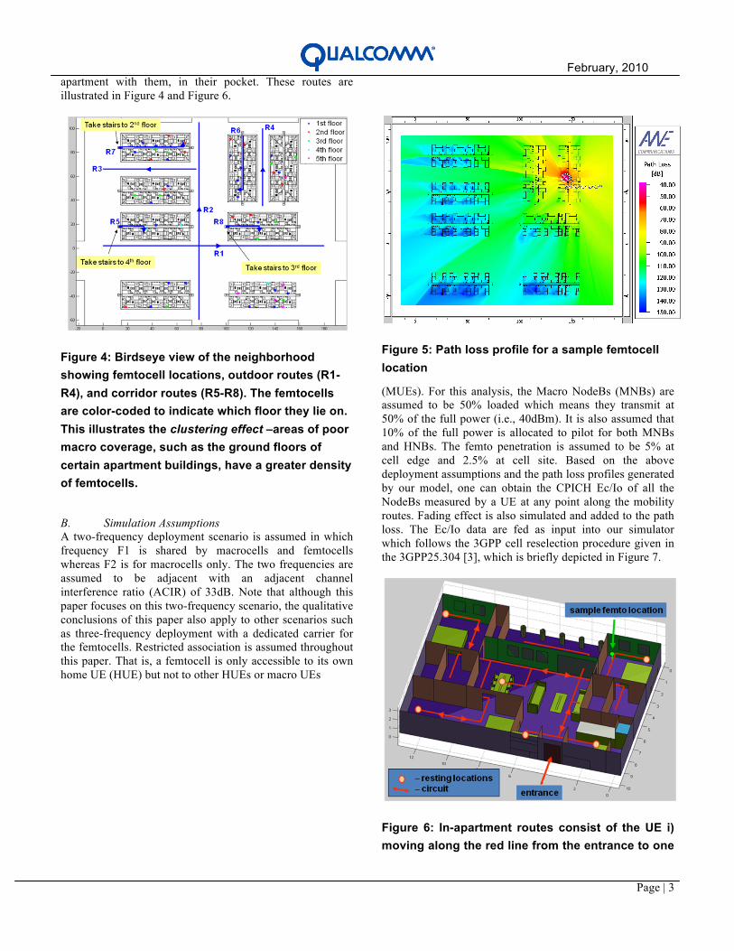
apartment with them, in their pocket. These routes are illustrated in Figure 4 and Figure 6.
Figure 4: Birdseye view of the neighborhood showing femtocell locations, outdoor routes (R1-R4), and corridor routes (R5-R8). The femtocells are color-coded to indicate which floor they lie on. This illustrates the clustering effect –areas of poor macro coverage, such as the ground floors of certain apartment buildings, have a greater density of femtocells.
B. Simulation Assumptions A two-frequency deployment scenario is assumed in which frequency F1 is shared by macrocells and femtocells whereas F2 is for macrocells only. The two frequencies are assumed to be adjacent with an adjacent channel interference ratio (ACIR) of 33dB. Note that although this paper focuses on this two-frequency scenario, the qualitative conclusions of this paper also apply to other scenarios such as three-frequency deployment with a dedicated carrier for the femtocells. Restricted association is assumed throughout this paper. That is, a femtocell is only accessible to its own home UE (HUE) but not to other HUEs or macro UEs
Figure 5: Path loss profile for a sample femtocell location
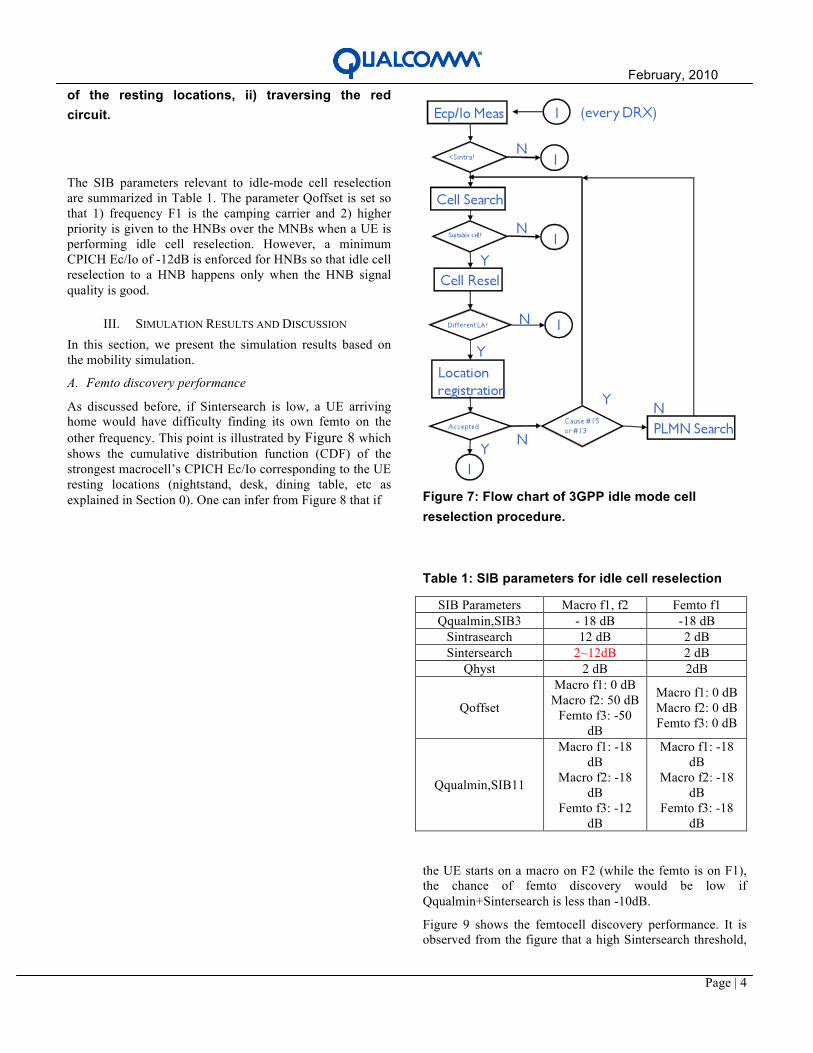
(MUEs). For this analysis, the Macro NodeBs (MNBs) are assumed to be 50% loaded which means they transmit at 50% of the full power (i.e., 40dBm). It is also assumed that 10% of the full power is allocated to pilot for both MNBs and HNBs. The femto penetration is assumed to be 5% at cell edge and 2.5% at cell site. Based on the above deployment assumptions and the path loss profiles generated by our model, one can obtain the CPICH Ec/Io of all the NodeBs measured by a UE at any point along the mobility routes. Fading effect is also simulated and added to the path loss. The Ec/Io data are fed as input into our simulator which follows the 3GPP cell reselection procedure given in the 3GPP25.304 [3], which is briefly depicted in Figure 7.
Figure 6: In-apartment routes consist of the UE i) moving along the red line from the entrance to one
February, 2010
Page | 4
of the resting locations, ii) traversing the red circuit.
The SIB parameters relevant to idle-mode cell reselection are summarized in Table 1. The parameter Qoffset is set so that 1) frequency F1 is the camping carrier and 2) higher priority is given to the HNBs over the MNBs when a UE is performing idle cell reselection. However, a minimum CPICH Ec/Io of -12dB is enforced for HNBs so that idle cell reselection to a HNB happens only when the HNB signal quality is good.
III. SIMULATION RESULTS AND DISCUSSION
In this section, we present the simulation results based on the mobility simulation.
A. Femto discovery performance
As discussed before, if Sintersearch is low, a UE arriving home would have difficulty finding its own femto on the other frequency. This point is illustrated by Figure 8 which shows the cumulative distribution function (CDF) of the strongest macrocell’s CPICH Ec/Io corresponding to the UE resting locations (nightstand, desk, dining table, etc as explained in Section 0). One can infer from Figure 8 that if
Figure 7: Flow chart of 3GPP idle mode cell reselection procedure.
Table 1: SIB parameters for idle cell reselection
SIB Parameters Macro f1, f2 Femto f1 Qqualmin,SIB3 - 18 dB -18 dB
Sintrasearch 12 dB 2 dB Sintersearch 2~12dB 2 dB
Qhyst 2 dB 2dB
Qoffset
Macro f1: 0 dB Macro f2: 50 dB
Femto f3: -50 dB
Macro f1: 0 dB Macro f2: 0 dB Femto f3: 0 dB
Qqualmin,SIB11
Macro f1: -18 dB
Macro f2: -18 dB
Femto f3: -12 dB
Macro f1: -18 dB
Macro f2: -18 dB
Femto f3: -18 dB
the UE starts on a macro on F2 (while the femto is on F1), the chance of femto discovery would be low if Qqualmin+Sintersearch is less than -10dB.
Figure 9 shows the femtocell discovery performance. It is observed from the figure that a high Sintersearch threshold,

February, 2010
Page | 5
e.g., 12dB or above, is necessary for guaranteed femto discovery.
Figure 8: CDF of CPICH Ec/Io of the strongest macro on F2 (different frequency than femtocell).
Figure 9: Femtocell discovery performance for different macro Sintersearch settings. Results are based on average over 10 locations. High Sintersearch threshold is needed for good femtocell discovery performance.
IV. ALTERNATIVE SOLUTIONS FOR FEMTOCELL
DISCOVERY
From the above analysis, we see that for good femtocell discovery performance, the Sintersearch needs to be set high which impacts all the UEs in the network. Hence, it is desirable to keep Sintersearch low without compromising femtocell discovery performance. To this end, we propose two solutions. One is through UE enhancements to perform autonomous periodic interfrequency searches irrespective of
the quality of the serving cell. The other is the so-called cell reselection beacon where the femtocell transmits a beacon on macro frequency(ies) to trigger reselection. The next two sections provide more details about the two proposed solutions.
V. UE ENHANCEMENT
One solution which can guarantee femto discovery without causing excessive cell search is the UE enhancement, for which the UE performs periodic interfrequency searches every few minutes (e.g., every two to five minutes) irrespective of serving cell quality. This method achieves very good femto discovery performance without a need to increase the macro Sintersearch setting. Once the UE finds a femto on the other frequency and its CPICH Ec/Io is higher than -12dB (cf. Table 1), the UE will attempt to reselect to the femto. As shown in Figure 10, the femto discovery performance of the HUE is greatly improved with the proposed slow background search (SBS). Here the period of the background search is 300sec. A major drawback of this method, however, is that it only applies to future UEs and does not solve the femtocell discovery issue for legacy UEs. To solve the femto discovery issue of legacy UEs, we
Figure 10: The UE enhancement with periodic background search significantly boosts femtocell discovery performance.
propose a cell reselection beacon as described in the next section.
VI. CELL RESELECTION BEACON
A. Basic Idea of Cell-Reselection Beacon
To facilitate femto discovery without increasing Sintersearch, the femtocell transmits a beacon signal on the macrocell’s frequency which reduces the CPICH Ec/Io of the macrocell to be lower than Qqualmin+Sintersearch. Hence the UE will perform interfrequency cell search when hit by the beacon even with low Sintersearch (e.g., 2dB). Since beacon can also cause interference to nearby MUEs, a

February, 2010
Page | 6
layered beacon design is proposed as illustrated in Figure 11. For most of time, the femto transmits a low-power beacon but every once a while a beacon burst with very short duration (a few msec) is transmitted at a higher power. The low-power beacon guarantees very fast cell reselection to femtocell when the HUE is in very close vicinity of the femto (e.g., within 45dB) while the high power beacon burst is meant to cover the entire apartment/house as illustrated in Figure 12.
Figure 11: Illustration of layered beacon design.
Consider an idle-mode UE which is within the coverage area of the high-power beacon and is camping on a strong macro on frequency F2. If the beacon burst coincides with the UE’s wake-up time, the measured CPICH Ec/Io of the serving macrocell (and any other neighbor cells on that frequency) will be low due to increased Io caused by the beacon burst as shown in Figure 13. Therefore, the UE will perform interfrequency search and will be likely to reselect to the femto (due to the Qoffset setting). At the same time since the beacon burst can cause interference to nearby MUEs (in voice call or data call) Hence the beacon pattern and transmit power needs to be chosen carefully to achieve good femtocell discovery while minimizing the interference to macro users. We have performed lab tests to evaluate the performance of the proposed cell-reselection beacon. The lab tests show that good femtocell discovery can be achieved with minimal impact on MUE performance.
Figure 12: Illustration of the coverage area of the layered beacon.
Figure 13: Bursty beacon temporarily reduces UE’s CPICH Ec/Io measurement of the cells on F2 to trigger cell search and reselection to femtocell on F1.

February, 2010
Page | 7
B. Lab Test Setting
The test equipments are shown in Figure 14. One MNB is deployed on frequency F1; one HNB is on frequency F2; one AWGN noise generator introduces noise on both frequencies to emulate Ioc; and a beacon signal generator whose output is modulated by a step attenuator A3 which is in turn controlled by a PC. The PC controls at any given time how much attenuation is applied to modulate the beacon power injected to the UE. The attenuators A1, A2, A3, and A4 are used to control the downlink/uplink path loss from UE to the NodeBs.
Figure 14: Beacon lab test set-up.
C. Femtocell DiscoveryPerformance
In the femtocell discovery test, the Sintersearch in macrocell’s SIB3 is set to be 2dB; the macrocell pathloss is set low to mimic a cell site scenario where the macro quality is very good and no interfrequency cell search would occur in the absence of the beacon. The Qoffset for the femto is set to be -50dB. Therefore, if the femto is found, it will be ranked the highest. Figure 15 shows the CDF of the time taken for UE to reselect to the femto. The time is defined as the duration between the moment when the beacon is turned on and the point when the cell reselection to the femto is complete. The average discovery time is 45 seconds. There are some rare occasions where the UE needs to wait about 5 minutes before it finally reselects to the femto.
Figure 15: Lab test results for femtocell discovery performance with beacon (Macro Sintersearch=2dB).
D. Voice Test The lab setup for the voice test is the same as Figure 14 except that the femto is turned off to make sure the UE stays on the macro. To quantify the impact of the beacon on the voice call quality of a neighbor UE, We initiate a voice call from the UE to the macro and measure the block error rate (BLER) at the UE side. Our tests show that in the presence of the bursty beacon, the increase in the BLER is negligible and the BLER is no more than 1% for all the test cases. To quantify the impact of beacon at the base-station side, we log the downlink DPCH Ec/Ior with and without beacon interference. It can be seen from Figure 16 that there is about 3dB increase of the transmit DPCH Ec/Ior when the UE is in the coverage area of the beacon. This increase is to compensate for the slots that are punctured by the beacon bursts (see Figure 12). Although the impact seems to be significant from Figure 16, it is limited to only the MUEs within the beacon coverage. If we take all the MUEs in the macrocell into account, the impact would be significantly diluted. Figure 17 shows the increase of DPCH Ec/Ior after averaging across all the UEs in the macrocell. One can see that the DPCH power increase is no greater than 1dB.
E. HS Throughput Test With the same lab setting as the voice call test, we have also tested the impact of the proposed cell-reselection beacon on HS data throughput (i.e., HSDPA throughput). Our tests show that the impact of the beacon on the peak HS throughput is no greater than 25% for the UE in the coverage area of the beacon when there is only a single user in the macro cell. When there are multiple HS users served by the same macrocell, the degradation in HSDPA throughput due to beacon bursts is even less.

February, 2010
Page | 8
Figure 16: Distribution of increase in Macro Node B DL power for a UE in voice call in the coverage area of beacon.
Figure 17: Distribution of increase in Macro NodeB DL power for all UEs across the macrocell.
VII. DISCUSSION AND CONCLUSION
It is desirable for users camped on macro and approaching their femtocells to discover and reselect to their femtocell even when femtocell is operating on another carrier. To ensure good femtocell discovery, the Sintersearch threshold broadcast by macro needs to be set high which impacts all the users in the network. We have proposed two solutions to facilitate femtocell discovery without requiring a high macro Sintersearch setting. One solution is through UE enhancement where UE performs periodic interfrequency search irrespective of the serving cell CPICH Ec/Io and the Sintersearch setting. The proposed UE enhancement works for future UE but it does not solve femto discovery issue of the legacy UEs. The alternative solution is for the femtocell to transmit beacons on macro frequency(ies). We have proposed a layered beacon design to achieve good femtocell discovery while minimizing interference to nearby MUEs. The lab test shows the proposed beacon enables femto discovery without increasing the Sintersearch. Moreover,
the proposed beacon solution has no impact on voice call quality and has only a small impact the HSDPA throughput of the nearby macro UEs in the coverage of the beacon. This makes the cell-reselection beacon an effective technique for solving the femto discovery issue for legacy UEs without changing the existing Sintersearch parameter of the macro network.
VIII. APPENDIX: MODEL CALIBRATION AND ACCURACY
Field measurements were used to aid in the selection of appropriate materials from the WinProp material database, and to get a sense of the accuracy of model. Data were collected in an apartment complex in Rancho Bernardo, CA. A total of 28 measurements were made with transmitter and receiver located in various positions in two neighboring apartments and the surrounding outdoor area. A WinProp model was created based on the apartment complex, and a set of building materials were chosen from the database to give good correlation between predictions and measurements. This material set was then used in the creation of the dense urban neighborhood. Figure 18 compares the measured and predicted path loss values. The standard deviation of the predictions from the measurements was 3.79 dB, indicating close agreement.
Figure 18: Measured vs. predicted path loss values
IX. REFERENCES
[1] M. Yavuz, F. Meshkati, S. Nanda, A. Pokhariyal, Nick Johnson, B. Raghothaman, and A. Richardson, “Interference Management and Performance Analysis of UMTS/HSPA+ Femtocells,” IEEE Comm. Magazine, vol. 47, pp. 102–109, Sep. 2009. [2] F. Meshkati, Y. Jiang, L. Grokop, S. Nagaraja, M. Yavuz, and S.Nanda, “Mobility and Capacity Offload for 3G UMTS Femtocells”, Proceedings of Globecom, Dec. 2009. [3] User Equipment (UE) procedures in idle mode and procedures for cell reselection in connected mode’, 3GPPTS25.304