mobile wheeled robot with step climbing...
TRANSCRIPT

3
Mobile Wheeled Robot with Step Climbing
Capabilities
Gary Boucher, Luz Maria Sanchez Louisiana State University, Department of Chemistry-Physics
Shreveport LA, USA
1. Introduction
The field of robotics continues to advance towards the ultimate goal of achieving fully autonomous machines to supplement and/or expand human-performed tasks. These tasks range from robotic manipulators that replace the repetitious and less precise movements of humans in factories and special operations to complex tasks which are too difficult or dangerous for humans. Thus an important and ever-evolving area is that of mobile robots. Extensive research has been done in the area of stair-climbing for mobile robotics platforms. Humanoid, wheeled, and tracked robots have all been made to climb stairs, however in most of these cases robots where designed for two dimensional operations and then later utilized or modified for stair climbing. (Herbert, 2008) Although strides have been made into exotic forms of legged robots, the conventional methods, such as wheels or tracks still form the basis for robotic locomotion. The wheeled mobile systems are useful for practical application compared with the legged systems because of the simplicity of the mechanisms and control systems and efficiency in energy consumption (Masayoshi Wada 2006). To better understand the problems faced by mobile ground based robots one must understand the expected terrain that the machine must negotiate. This can range from un-level ground to rocky and irregular terrain and in some cases man-made obstacles such as steps or stairs must be climbed. Each of these applications has unique challenges and solutions. In 2003, Louisiana State University-Shreveport took on the task to create an alternate approach to a rugged terrain robot capable of traversing not only rough terrain, but also man-made obstacles, such as steps and stairs, with the intent to meet the requirement to ascend and descend between levels in a building as in the case of security robots performing their tasks. The project further addressed the issue of observation capabilities to handle obstacles in the robot’s path. In conjunction with our Computer Science CSC 410 course in robotics, the LSUS Department of Chemistry-Physics took up the challenge to develop a robotic design that would meet these requirements. The criteria that factored into the initial concept phase of the project were the following: First the robot must be robust, capable of extended service in rugged environments and carry its own power source. Secondly, the robot must also have versatile vision systems which can relay the video information back to the operator via radio signals
www.intechopen.com
Mobile Robots - State of the Art in Land, Sea, Air, and Collaborative Missions50
or a fibre optic link. Thirdly, the device should have the ability to climb steps and stairs for changing floors in a building. The challenge was then handed to the students A robot using more than four wheels could compete with some tracked devices if the wheels are driven simultaneously. One approach considered to meet this requirement was through the use of a hydraulic motor on each wheel. This would allow all wheels to derive their rotation from one single power source. A central hydraulic pump generating a constant flow of fluid could provide the source to power the device. This concept was first patented by Joseph Joy in 1946 (Joy, 1946). Joy described a 16 wheel automobile capable of being driven by 8 hydraulic motors powered by a single engine and hydraulic pump. Such a scheme for driving a robot would require two hydraulic pumps and two sets of motors, one set for the left and one for the right side of the robot. The differential drive would then allow turning much the same way as tank treads. The motors could be in series on each side and therefore produce the same rotation for the volume of fluid pumped. Hydraulic pumps and motors were ruled out in the LSUS robot due to cost and the shear bulk of two hydraulic systems with proportional rate of flow control. The concept of wheel sets that can rotate is also not new. As far back as 1932 Raphael Porcello patented their use in numerous mobile devices from baby carriages to landing gear for airplanes (Porcello, 1932). Although not driven, these wheel sets demonstrated the versatility of allowing wheels to be grouped together and have their individual axels fixed at a certain common radius from the axes of wheel set rotation. The LSUS design consensus centered on using sets of two wheels that used parallel individual axels each offset a given radius from the wheel set axis of rotation. In this way, the wheels could revolve and also be powered from a source of angular speed and torque. The wheels sets could also revolve in any direction independent of the rotation of the wheels. This design seemed to satisfy the primary requirements for the robot for both rough terrain and stair climbing.
2. Related Work
In 1991 King et al patented a method of stair climbing using a robot with rotating wheel sets (King et al, 1991). This device used two sets of two wheels each for stepping and used a larger front wheel to ride up and over oncoming steps. This larger wheel was forced by the rotating rear wheel sets. This novel approach used counter rotation between the rear wheel sets and the individual wheels in the sets. Thus, if properly geared, each wheel set would “step” motionless on each stair step without rotating relative to the stairs. This requires the proper ratio of wheel set speed and rotational speed for the tires. The early work by King et al was followed by several unique approaches to rotating wheel sets for stair climbing robots. Andrew Poulter set forth the concept of a robotic all-terrain device that consisted of two elliptical halves or “clam shells” that supported the drive mechanism for two wheels (Poulter, 2006). These clam shells were articulated as connected together with a common shaft. In this way, the robot could almost continuously have all four wheels in touch with the surface. Although not intended for stair climbing this device demonstrated articulated wheel sets. Poulter also used a long boom situated between the two clam shells that could be rotated to right the vehicle should it topple over or need to raise the forward or rear wheel sets. This
www.intechopen.com

Mobile Wheeled Robot with Step Climbing Capabilities 51
device also incorporated the concept of having no front or rear, handling either direction desired as forward. In 1998 Yasuhiko Eguchi from Heyagawa, Japan was issued a patent on a system of eight wheels driven in sets of two wheels each (Eguchi, 1998). This system could both rotate wheel sets and drive the wheels individually and separately. This vehicle had its individual wheel drive and wheel set drive linked using gears. As the wheel sets were driven, the gears would transfer torque to the individual wheels. Having the power transferred in this way caused the wheel sets to rotate opposite to the wheels, much the same as King et al. The LSUS robot design paralleled the Eguchi concept set forth in his 1998 patent. As far as the authors are concerned, the LSUS design is the first prototype of its kind that applies the Eguchi concept and combines stair climbing with rough terrain negotiation capabilities. The LSUS adaptation of this wheel set concept for robotics limited the rotation of the wheel sets to approximately 35 degrees in either direction from level using pneumatic cylinders affixed to each of the wheel sets. The type of pneumatic control valves allowed a step up or down of the wheel sets and also a “neutral” position where the air valves allow full and free motion as will be discussed later in this chapter. Also, the use of chain drive rather than gears was incorporated in the LSUS robot. This less expensive alternative to gears requires lower maintenance and is easily replaced should failure occur. Other works that apply the Eguchi concept for stair climbing is that of Minoru et al, 1995 although with Figure 1 shows WHEELMA (Wheeled Hybrid Electronically Engineered Linear Motion Apparatus), the LSUS designed robot that uses the Eguchi concept.
Fig.1. Wheelma Robot based on Eguchi system
www.intechopen.com
Mobile Robots - State of the Art in Land, Sea, Air, and Collaborative Missions52
Extreme examples of wheeled robots use multiple wheel drive that is articulated not in a rotary manner but in a vertical manner. A vertically wheel articulated system is seen in a design by the Intelligent Robotics Research Centre in Clayton Victoria Australia (Jarvis, 1997). This robot, the size of a small car, uses six wheels that can move vertically to negotiate rough terrain. This robot was inspired by a Russian model of a Marsokhod Mars Rover M96. This robot was been located at the Intelligent Robotics Research Centre at Monash University since 1997. Another unique example of articulated wheeled robots is the Octopus developed by the Swiss Federal Institute of Technology Zurich (Lauria et al, 2002). This wheeled design uses tactile sensing in each wheel to identify and negotiate obstacles. This robot’s instrumentation can identify the height of obstacles and the system can decide how to handle the obstacle such as total avoidance or decide a strategy to overcome the obstacle. This eight-wheeled robot is small and can be configured to a variety of wheel configurations.
3. WHEELMA
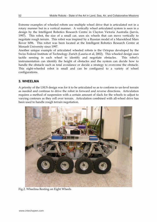
A priority of the LSUS design was for it to be articulated so as to conform to un-level terrain as needed and continue to drive the robot in forward and reverse directions. Articulation requires a method of suspension with a certain amount of slack for the wheels to adjust to varying contours as they roll over terrain. Articulation combined with all-wheel drive has been used to handle rough terrain negotiation.
Fig.2. Wheelma Resting on Eight Wheels
www.intechopen.com
Mobile Wheeled Robot with Step Climbing Capabilities 53
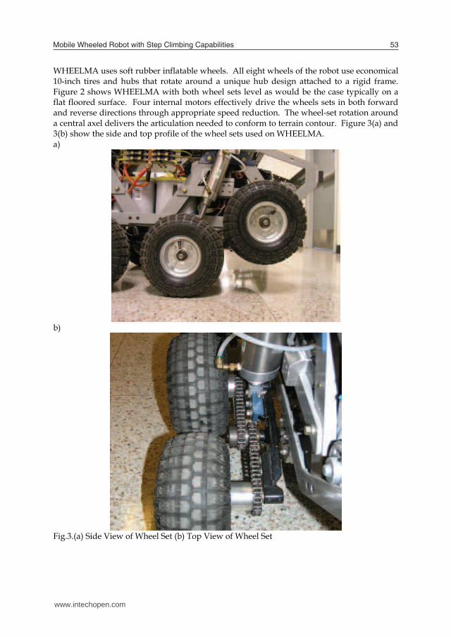
WHEELMA uses soft rubber inflatable wheels. All eight wheels of the robot use economical 10-inch tires and hubs that rotate around a unique hub design attached to a rigid frame. Figure 2 shows WHEELMA with both wheel sets level as would be the case typically on a flat floored surface. Four internal motors effectively drive the wheels sets in both forward and reverse directions through appropriate speed reduction. The wheel-set rotation around a central axel delivers the articulation needed to conform to terrain contour. Figure 3(a) and 3(b) show the side and top profile of the wheel sets used on WHEELMA. a)
b)
Fig.3.(a) Side View of Wheel Set (b) Top View of Wheel Set
www.intechopen.com

Mobile Robots - State of the Art in Land, Sea, Air, and Collaborative Missions54
This design further allows fulfillment of the above stated design criterion with the use of a simple left-right differential control system, similar to the classic arcade game “Tank.” Each control device or lever controls one side of the robot. The left control drives the two left wheel sets, while the right control drives the right side wheel sets. This allows forward and reverse motion and also rotation around an axis central to the robot in a fashion similar to a tracked vehicle. Each wheel set has two wheel axels that are attached to a cross bar. Figure 3(b) shows the crossbar. The 1.25-inch axel that passes through two ball bearings (not shown) held in place by the robot’s frame allows full articulation of the wheel sets. Inside each of these 1.25-inch axels is set of two needle bearings that support a second 0.5-inch axel used for driving the two wheels. Thus, an axel inside an axel enables rotation and horizontal translation for the wheel-sets. To allow for the tank-like operation of the robot, all wheel sets are allowed to “float” at times creating a contour following approach similar to a treaded vehicle. The wheel-sets also must encompass a control mode where they can both be locked or driven. With each wheel set in either of these two modes, it must be driven through the central drive shaft for locomotion of the robot. The initial approach utilized in WHEELMA used electric clutches that allowed floating operation where the terrain requires such and locked rotation where needed for confronting obstacles. The clutches would be activated to thus be driven by a high torque source to rotate each wheel-set. This approach could deliver stair climbing capabilities. Full rotational capabilities for each wheel set would demand a method of monitoring the position of each wheel-set. This task could be accomplished by means of an optical encoder. The optical encoder would digitally measure the angle of rotation for each wheel set shaft. As the shaft moves, digital pulses would be counted and at any given time the counter could be read to determine the position of the encoder and thus the position of the wheel-sets for this application. This method of sensing would require an index mark where the electronics used for counting rotation pulses could find the level position and zero the counters that measured angular displacement. Otherwise, the encoder and digital circuit would not know when the sets were level. The clutch based system posed one daunting problem, in case of a power failure the clutches would disengage. If this occurred while the robot was climbing stairs the clutches would in turn release the wheel-sets causing a catastrophic loss of control. An alternate approach to the electric clutches was devised. The new approach would limit the wheel set movement to approximately 35 degrees clockwise and counterclockwise. Although agility would be compromised, this approach would allow upward rotation for oncoming obstacles such as curbs and steps as well as rotation in the opposite direction for possible clearing of the robot from stuck positions. While continuous rotation may have been more beneficial to certain climbing operations the simpler approach was found to be more adequate for most operations. A method to lower and raise each set of wheels was the next step in the design. The chosen approach replaces the clutches and drive mechanisms with four 2-inch diameter bore pneumatic cylinders each with its own air control valve operated electrically. This system solves two issues. It provides the wheel sets rotation and also afforded a method of achieving the “float” condition, which allows the wheel-set’s unhampered movement as the robot negotiates terrain.
www.intechopen.com
Mobile Wheeled Robot with Step Climbing Capabilities 55
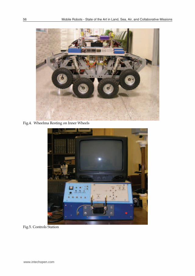
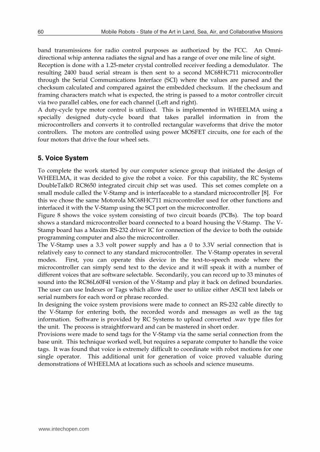
The float condition is achieved with the use of pneumatic control valves that have an off or neutral position which allows for the exhausting of both ports of the double acting cylinders to the outside air. Thus, when the wheel-sets rotate in one direction outside air is drawn into one double acting cylinder on one end and exhausted from the other. The use of exhaust filters addressed the resulting drawback of dirty air entering the system that could cause a buildup of debris in the air valves and cylinders. Electronic control for each wheel-set is initiated by the ground based control unit and once this control information reaches the robot, power Darlington transistors control the current to actuate the pneumatic control valves. This separate control over each wheel-set was found to have great utility in ways not initially conceived. This independent wheel-set control further facilitates the turning of the robot on surfaces that afforded a high coefficient of friction between the robot wheels and the surface. This was first noted on concrete where the coefficient of friction can be as high as 1. Turning with all eight wheels in the floating position requires a great deal of wheel torque due to the extended front and back wheels having to slide laterally to some extent due to the general nature of all differentially operated locomotion systems. Since the vehicle can lift the outer ends of its tracks, or outer wheels in the case of WHEELMA, the device can turn on the inner portions of the tracks or the four inner wheels. This fact proved invaluable for turning with lower levels of power especially when the robot had been working and the batteries were supplying lower voltage and the electronics and motors were reaching higher temperatures all of which reduce the drive torque. Raising the outer wheels places the same weight loading totally on the inner wheels maintaining approximately the same amount of friction between the surface and drive system. Much of the turning friction is reduced by the shortened moment arms of the inner wheels which allow for much lower resistance when turning since the resulting wheel drag will be decreased. Effectively shortening the length of the robot allows for far less lateral or non-rotational component yielding a greater turning ability. The control portion of WHEELMA consists of a custom built base station which provides switches for defining options on the robot along with the standard two levers for the differential driving of the device in forward and reverse directions much the same as a tank. Figure 5 shows the base station along with associated switches, receiver controls, and TV for monitoring returning video from the robot.
www.intechopen.com
Mobile Robots - State of the Art in Land, Sea, Air, and Collaborative Missions56
Fig.4. Wheelma Resting on Inner Wheels
Fig.5. Controls Station
www.intechopen.com

Mobile Wheeled Robot with Step Climbing Capabilities 57
4. Vision System and Directional Orientation
Many robotic designs rely on either physically turning the robot around 180 degrees to exit tight situations or else attempt to back out of restrictive spaces the same way they were entered. Many robots have the ability to reverse their viewing direction either by rotation of the camera or by using a secondary camera mounted to look aft. It is also difficult to convey to an observer the lack of depth perception that occurs while using only one robotic camera at a time. Although two cameras could afford a stereo view of the operating area to the operator wearing a head-mounted viewing device, the difficulty in transmitting two simultaneous video signals precludes this practice for more applications. Such transmissions are often plagued by the need for excess transmission bandwidth for transmission or inter-modulation between two closely spaced video transmitters operating at nearly the same carrier frequency. Using one camera for forward and one for reverse makes driving the robot easier in close quarters as the operator can always be looking in the direction of travel. This approach can, in some cases, eliminate having to perform a 180 degree turn by simply switching cameras and backing out of a given situation. Reversing the view however does not in itself reverse the control action necessary to drive the robot. This fact makes the operation extremely disorienting to the operator. Also the drive characteristics of the robot may change for certain robots used in the reverse mode of travel. Because WHEELMA is basically symmetrical with no difference in handling characteristics in forward or reverse, the ability to reverse the robot’s direction of control was incorporated. The video circuit has provisions for up to eight cameras multiplexed through a specially designed video multiplexer controlled by the base station. This multiplexer feeds a single video output from one camera at any given time to the video transmitter on the robot. This allows for easy installation of two cameras, one at each end of the robot. Figure 6 shows the video multiplexer. This multiplexer board uses two DG540DN video multiplexers which are under the control of the robot logic. This video multiplexer has the feature of using two analog CMOS switches in series to pass the video signal. When the channel is not selected the switches both go to the open mode and a third switch grounds the connection between the two. This lowers crosstalk to a minimum. Although there are eight possible connections to this multiplexer, only two are used for WHEELMA’s cameras. Refer to Figure 1 and 2 for a view of the cameras used. These cameras in the figures are in small square enclosures. Each looks toward its respective end of the robot.
www.intechopen.com

Mobile Robots - State of the Art in Land, Sea, Air, and Collaborative Missions58
Fig.6. Video Multiplexer
Fig.7. DPDT Relay
Using a reversing strategy allows the operator to literally switch ends with the robot with the change of a single toggle switch at the base station. This toggle will switch the cameras, the left and right controllers, and even the lighting on the robot. In this way if WHEELMA enters a room and the remote operator desires to exit the room, one flip of a switch causes the view to change along with all necessary controls and lighting to simply drive out. Thus, WHEELMA has no front-back orientation and relies solely on the remote operator’s manipulation of the direction switch. Figure 7 shows the simple strategy for accomplishing a total reversal. A DPDT relay is shown that is driven by an SPST reversing switch. Lighting control is not shown, but can be added with using the microprocessor’s logic located in the base station. Note that power is DC voltage and is supplied to two potentiometers connected to the left and right drive control levers (tank controls). When the relay is activated the polarity of the signal going to the two pots is reversed thus changing the directional nature of the controls Secondarily the
www.intechopen.com

Mobile Wheeled Robot with Step Climbing Capabilities 59
left-right input from the pots are also switched to compensate for the left-right reversal effect. One switch can thus control a total reversal of control operation. It should not be construed that the robot cannot reverse and back out of a tight location maintaining the same front-back orientation that carried the device into the room. The robot can also switch cameras and back out without reversal. However, using this system is seamless in operation and solves many problems encountered with some robots. When setting up such a reversing control system, once should endeavor to place the zero thrust position in the exact vertical center position of the levers. Thus, when the left and right control levers are centered there is no thrust to the robot wheels. This is extremely important when doing a reversal as any residual thrust at the time of reversal will become an opposite thrust upon reversal. Several times WHEELMA operators have become disoriented through a combination of slight forward or reverse thrust set by the levers at the time of reversal. It would be good design practice to either not allow reversal with thrust applied or to have a centering method to be assured that no residual thrust is present in the control lever settings when a reversal is undertaken. Allowing a spring loaded return to center for the thrust levers along with an indicator for denoting zero thrust could be used to prevent this effect.
5. Control Link
A simple system using the 1.25-meter amateur radio band was used to transmit all of the control signals from the base station to WHEELMA. This band of frequencies available to all amateur radio operators for sending ASCII packets was used in this and other previous robotic designs. (CGS Network) The motor control information begins at the two-lever input for the tank-like control of the robot. These two levers are attached to two high quality potentiometers that divide the applied 5-volt potential. With each lever in the center position (vertical) the voltage is measured as 2.5 volts. As the levers are moved forward and backward the voltages rise and fall above and below this 2.5-volt center value. The voltages are conditioned via an operational amplifier interface before being presented to a Motorola MC68HC711 microcontroller where the 8-bit A to D converters sample the voltage levels. Each voltage level is then converted into a 2’s compliment signed number that is transmitted to the robot’s receiver. A continuous stream of these sampled lever voltages are sent using ASCII transmission techniques. Each complete motor control sample is sent as one line of ASCII text followed with Return and Line Feed characters. Each text string transmitted contains a starting character. A colon (:) was chosen to begin each string. Following the colon two ASCII bytes are transmitted representing the 2’s compliment signed motor control sample position of the left lever for the left motor sets. Then the right motor set sample is sent using another two ASCII characters. At this point in the stream a simple checksum is transmitted followed by a Return and Line Feed. These two control characters in ASCII have provided a good way of showing all control information using a simple computer terminal for debugging purposes. This stream of serial information at 2400 baud is sent to a modulator where it is converted to a standard FSK audio signal. This signal is then transferred to an amateur FM modulated transmitter operating on the 1.25-meter band. This 1-watt unit is the legal limit for amateur
www.intechopen.com
Mobile Robots - State of the Art in Land, Sea, Air, and Collaborative Missions60
band transmissions for radio control purposes as authorized by the FCC. An Omni-directional whip antenna radiates the signal and has a range of over one mile line of sight. Reception is done with a 1.25-meter crystal controlled receiver feeding a demodulator. The resulting 2400 baud serial stream is then sent to a second MC68HC711 microcontroller through the Serial Communications Interface (SCI) where the values are parsed and the checksum calculated and compared against the embedded checksum. If the checksum and framing characters match what is expected, the string is passed to a motor controller circuit via two parallel cables, one for each channel (Left and right). A duty-cycle type motor control is utilized. This is implemented in WHEELMA using a specially designed duty-cycle board that takes parallel information in from the microcontrollers and converts it to controlled rectangular waveforms that drive the motor controllers. The motors are controlled using power MOSFET circuits, one for each of the four motors that drive the four wheel sets.
5. Voice System
To complete the work started by our computer science group that initiated the design of WHEELMA, it was decided to give the robot a voice. For this capability, the RC Systems DoubleTalk© RC8650 integrated circuit chip set was used. This set comes complete on a small module called the V-Stamp and is interfaceable to a standard microcontroller [8]. For this we chose the same Motorola MC68HC711 microcontroller used for other functions and interfaced it with the V-Stamp using the SCI port on the microcontroller. Figure 8 shows the voice system consisting of two circuit boards (PCBs). The top board shows a standard microcontroller board connected to a board housing the V-Stamp. The V-Stamp board has a Maxim RS-232 driver IC for connection of the device to both the outside programming computer and also the microcontroller. The V-Stamp uses a 3.3 volt power supply and has a 0 to 3.3V serial connection that is relatively easy to connect to any standard microcontroller. The V-Stamp operates in several modes. First, you can operate this device in the text-to-speech mode where the microcontroller can simply send text to the device and it will speak it with a number of different voices that are software selectable. Secondarily, you can record up to 33 minutes of sound into the RC86L60F4I version of the V-Stamp and play it back on defined boundaries. The user can use Indexes or Tags which allow the user to utilize either ASCII text labels or serial numbers for each word or phrase recorded. In designing the voice system provisions were made to connect an RS-232 cable directly to the V-Stamp for entering both, the recorded words and messages as well as the tag information. Software is provided by RC Systems to upload converted .wav type files for the unit. The process is straightforward and can be mastered in short order. Provisions were made to send tags for the V-Stamp via the same serial connection from the base unit. This technique worked well, but requires a separate computer to handle the voice tags. It was found that voice is extremely difficult to coordinate with robot motions for one single operator. This additional unit for generation of voice proved valuable during demonstrations of WHEELMA at locations such as schools and science museums.
www.intechopen.com
Mobile Wheeled Robot with Step Climbing Capabilities 61
6. Future Work
One preferred embodiment of a WHEELMA-type robot would be to return to the 360 degree wheel set rotation concept of Eguchi but replace the two-wheel sets with three-wheel sets. The three wheel sets would rotate into position easier in the process of climbing stairs and should have extremely good functionality in the negotiation of rough terrain. This should prove highly effective as the wheels sets can rotate for propulsion as well as being driven in the conventional manner. Similar devices have been developed for carrying heavy loads up stairs using a three-wheel drive mechanism.
7. References Sam D. Herbert, Andrew Drenner, and Nikolaos Papanikolopoulos “Loper: A Quadruped-Hybrid Stair Climbing Robot” 2008 IEEE International Conference on Robotics and Automation Pasadena, CA, USA, May 19-23, 2008 Masayoshi Wada “Studies on 4WD Mobile Robots Climbing Up a Step” Proceedings of the 2006 IEEE International Conference on Robotics and Biomimetics December 17 - 20, 2006, Kunming, China Joseph Joy. “Automotive Vehicle” Patent 2393324 Application September 18,1982,
Serial No. 458,886 I1 Claims. (a.18 0-17) Raphael Porcello “Wheeled Device” Patent 1887427 April 6, 1932
Edward G. King, Baltimore; H. Shackelord, Jr., Finksburg; Leo M. Kahl, Baltimore, all of Md. Patent 4993912 February 19,1991.
Andrew R. Poulter 80128 United States “Rugged Terrain Robot” Patent (10) Patent NO.: US 7,011,171-BI Poulter (45) Mar. 14,2006 Yasuhiko Eguchi “Stairway Ascending/Descending Vehicle Having an Arm Member with a Torque Transmitting Configuration” Patent 5833248 Nov 10,1998. Ray A. Jarvis, “Autonomous Navigation of a Martian Rover in Very Rough Terrain” Proc. International Symposum on Experimental Robotics, March 26-28 1999, Sydney University, pp.225-234 Lauria, Piguet and Siegwart, R “Octopus – An Autonomous Wheeled Climbing Robot” Proceedings of the Fifth International Conference on Climbing and Walking Robots, 2002. CSG Network (2008). http://www.csgnetwork.com/hamfreqtable.html :accessed Aug 2008
www.intechopen.com

Mobile Robots - State of the Art in Land, Sea, Air, and Collaborative Missions62
www.intechopen.com
Mobile Robots - State of the Art in Land, Sea, Air, andCollaborative MissionsEdited by XiaoQiChen
ISBN 978-953-307-001-8Hard cover, 335 pagesPublisher InTechPublished online 01, May, 2009Published in print edition May, 2009
InTech EuropeUniversity Campus STeP Ri Slavka Krautzeka 83/A 51000 Rijeka, Croatia Phone: +385 (51) 770 447 Fax: +385 (51) 686 166
InTech ChinaUnit 405, Office Block, Hotel Equatorial Shanghai No.65, Yan An Road (West), Shanghai, 200040, China
Phone: +86-21-62489820 Fax: +86-21-62489821
Since the introduction of the first industrial robot Unimate in a General Motors automobile factory in NewJersey in 1961, robots have gained stronger and stronger foothold in the industry. In the meantime, roboticsresearch has been expanding from fix based robots to mobile robots at a stunning pace. There have beensignificant milestones that are worth noting in recent decades. Examples are the octopus-like Tentacle Armdeveloped by Marvin Minsky in 1968, the Stanford Cart crossing a chair-filled room without human assistancein 1979, and most recently, humanoid robots developed by Honda. Despite rapid technological developmentsand extensive research efforts in mobility, perception, navigation and control, mobile robots still fare badly incomparison with human abilities. For example, in physical interactions with subjects and objects in anoperational environment, a human being can easily relies on his/her intuitively force-based servoing toaccomplish contact tasks, handling and processing materials and interacting with people safely and precisely.The intuitiveness, learning ability and contextual knowledge, which are natural part of human instincts, arehard to come by for robots. The above observations simply highlight the monumental works and challengesahead when researchers aspire to turn mobile robots to greater benefits to humankinds. This book is by nomeans to address all the issues associated mobile robots, but reports current states of some challengingresearch projects in mobile robotics ranging from land, humanoid, underwater, aerial robots, to rehabilitation.
How to referenceIn order to correctly reference this scholarly work, feel free to copy and paste the following:
Gary Boucher and Luz Maria Sanchez (2009). Mobile Wheeled Robot with Step Climbing Capabilities, MobileRobots - State of the Art in Land, Sea, Air, and Collaborative Missions, XiaoQiChen (Ed.), ISBN: 978-953-307-001-8, InTech, Available from: http://www.intechopen.com/books/mobile-robots-state-of-the-art-in-land-sea-air-and-collaborative-missions/mobile-wheeled-robot-with-step-climbing-capabilities
www.intechopen.com

www.intechopen.com

© 2009 The Author(s). Licensee IntechOpen. This chapter is distributedunder the terms of the Creative Commons Attribution-NonCommercial-ShareAlike-3.0 License, which permits use, distribution and reproduction fornon-commercial purposes, provided the original is properly cited andderivative works building on this content are distributed under the samelicense.