mobile robots exploration and mapping in 2d - asee. · pdf filemobile robots exploration and...
TRANSCRIPT
1
ASEE 2014 Zone I Conference, April 3-5, 2014, University of Bridgeport, Bridgpeort, CT, USA.
Mobile Robots Exploration and Mapping in 2D
Sithisone Kalaya Robotics, Intelligent Sensing & Control (RISC) Laboratory,
School of Engineering, University of Bridgeport, 221 University Avenue, Bridgeport, CT 06604, USA.
Hussain A. Alhazmi Robotics, Intelligent Sensing & Control (RISC) Laboratory,
School of Engineering, University of Bridgeport, 221 University Avenue, Bridgeport, CT 06604, USA.
Abstract – In this paper, we present a system for multi-robot exploration of an unknown environment, taking into account the communication constraints between the robots. The objectives of the robots are to explore the whole environment as a group, while maintaining communication with base computer throughout the entire exploration. Our method was implemented using a mobile robot equipped with a sonar range finder, a communication unit, and a software module. The robots perform collision free navigation, dynamic object detection, data collection, and communication with a base computer. The base computer is accountable for data processing, and map construction according to data received from the robots. This work demonstrates that multiple robots can improve overall mapping performance of an unknown environment.
Keywords- SLAM, mobile robot, mapping, obstacle avoidance
I. INTRODUCTION The ability of a mobile robot to move freely, avoiding
obstacle, collecting data while exploring the environment, and transferring these data to a host computer are considered to be the initial problems in this work. Subsequently, we would like to develop our mobile robot to have the capabilities to localize itself in an unknown environment as well as the ability to create the local map from data collected during the exploration. Communication link between the robots and a host computer is essentials in this experiment because the mobile robots continuously streaming data to the host computer. The tasks such as data storages, retrieval, computations, and mapping are to be executed in the host computer. Earlier researches in robot exploration and mapping dealt with individual and larger robots equipped with more advance sensors such as 3D scanning systems with laser time of flight measurement devices, sonars range finder,
PTZ camera, and Sick laser in [1, 2]. We felt the previous method resulted in bulkier robots which prevented their mobile robot to move freely in a crowded indoor environment. In addition these robots are also more complex to make and maintain.
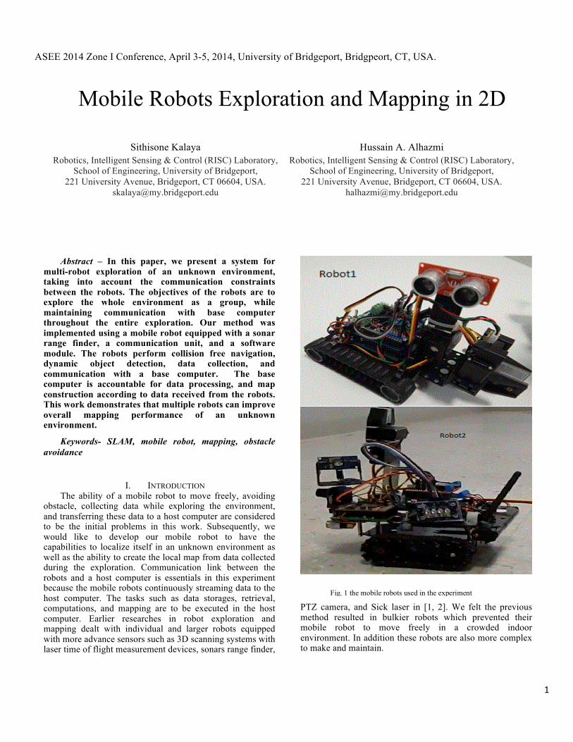
Fig. 1 the mobile robots used in the experiment

2
In this paper, we applied a system consisting of simpler, smaller robots (see fig.1), and a host computer. This system is capable of exploring and gathering information in an office-like environment and construction of a map from data collected. The approaches we used required two simple tasks. These are: robots task and host computer task. The robot is capable of moving freely, avoiding any obstacle in its path, measuring ranges information provided by sonar range measuring device, and communicating to a host computer. The object avoidance capability on the mobile robots is based on the algorithm using heading range information provided by front mounted measuring sonar device. A transmission of data between mobile robots to a host computer, we used communication unit installed on each robot as well as on a host computer. When we start the exploration each robot will be place at the closest starting location heading in the opposite directions. While exploring the given environment each robot’s pose and landmarks ranges are sent to the host computer for storage. These data will be processed by the software computation module for map construction at the end of the exploration.
II. RELATED WORK For many years, a lot of study has been done in mapping
and exploration using single and multiple robot systems. Some of the earliest studies in the field have been developed by [4], which implemented a single mobile robot with a camera to exploit the visual information obtained by scanning a room to determine its size and shape, and continually orient itself within it. The higher accuracy and faster mapping technique such as in [1] was based on a similar idea with [2] but applied the method called laser time-of-flight measurement, simply using a standard 2D laser scanner and a mechanical actuator to reach the 3rd dimension. A more advanced research similar to [1] was developed using Panoramic and Active Camera of Object Mapping(PACOM) [5]. This complex system can build a semantic map which contains a high-level of information similar to those extracted by humans and can be rapidly and easily interpreted by users to assess the situation. In [6] also propose a technique called ARIEL, which is a mobile robot system that combines frontier based exploration with continuous localization. A similar technique was also used in [7], the Autonomous Intelligent Knowledge-building Exploration (AIKE) system. To start, the AIKE generates grid-based maps and continuously refine the map building until the exploration is completed. Later on, the exploration of an unknown environment with the multi-robots system approach which in theory can do the task in less time. In [8] [9] [3] was developed to prove the concept. The system deployed multiple-robots each linked to a single global map. The coordination and calculation was distributed among the individual robots and the results were asynchronously integrated by performing complexes global computations over the data. The approach in [6] creates a central mapper module then it integrates the local maps to create a consistent global map. The central mapper further improves the map by iteratively combining data from the robots. However, in [7] uses a Sherwood algorithm approach based on a dynamic
area for the multi-robots Simultaneous Localization and Mapping (SLAM) and in [8] make an improvement even more by applying an analysis of the Extended Kalman Filter Formulation of Simultaneous Localization and Mapping (EKF-SLAM). These two techniques were accomplished through complex mathematical computation and algorithm which can be summarized in the following steps:
a) Each robot starts at an arbitrary unknown location and incrementally builds a local map of the environment while using its abilities to localize itself. It then sends the information of the local maps to the host.
b) The host matches the pose of the robot and the boundary of the robots. It can build a joint map between the already existing maps. These robots can then be able to localize themselves in the joint map.
c) The unknown area near the joint map was divided into a number of zones by the host; the host distributed the task of exploring unknown zones to the robots in the joint map.
d) The robots surveyed the assigned task and sent back information to the host computer.
e) When an overlap with any robot in the team has been determined by the host, a joint map of the team can be built and the exact pose of all robots relative to each other can be known.
A similar technique which combined in [4] [8] [9] [3] was also developed in [10] which this technique was aimed at implementing the robots to explore the whole map as a pack. Each robot would maintain its communication throughout the exploration. Paths planning for each robot are essential in this technique. Hence resulting in a well-executed planning outcome and maximized the area of exploration, and minimizing amount of time. As a result in [10] maximize the information gained while minimizing the distance to be travelled to the given environment.
III. SYSTEM OVERVIEW A. System Architecture
We constructed two mobile robots for this research based on DFRobotShop Rover V2-Arduino Compatible Tracked Robot from RoboShop. The robot was fitted with a Seeed Ultrasonic Sensor, a distance measuring module and a Bluetooth/XBee communication device. The Seeed Ultrasonic Sensor provided detecting range from three centimeters to 400 centimeters at 40k Hz frequency. The Seed Ultrasonic Sensor is positioned in front of the robot on a simple servo-based pan system (see fig. 2). This sensor provides three measured distances in 180o sonar scan coverage. The three measured information are taken from left, front, and right of the robot each at an angle 90o apart (see fig. 3). It is vital that these values are taken in every twenty centimeters apart when moved in forward direction. Since the summation of forward moving direction provided a rough estimated of a room’s length.

3
The software module uses the ARDUINO1 IDE framework which is an open-source used for programming electronics prototyping platform developed and supported by Arduino. This language incorporates high-level features that facilitate the development of parallel and event-based applications. On the host computer we used a Bluetooth/XBee communication unit to ensure a constant communication link between the robots and host computer. On our host computer we also installed Putty release 0.63, a Telnet/SSH client for Windows and terminal emulator. The software is being implemented to enable data transmission from the robot to a host computer. In this project, we developed the program by carrying out the various necessary functionalities based on information received from the robot sensors.
B. Basic Navigation
The robot’s control system consists of three main components integrated into a homogeneous event-based representation that is.
a) Navigation such as obstacle avoidance and boundary tracing.
b) Communication and data transmission. c) Map construction and map updating.
The navigation algorithm primary task was to keep the robot moving safely in the unexplored environment. The mobile robot is designed based on the concept of even-driven terminology. That it reacts by moving forward, turning left/right, or stops and reverse to avoid obstacle and maintain a minimal distance from any objects (see fig. 2). This behavior is useful as the accuracy of the sonars is maximized in the proximity of detectable objects. This is important due to the fact the robot sensors are the only way to obtain information about the environment. To ensure that the robot can move freely in the unknown environment we separated its boundaries based on the circular arrangement of the sonars. This is to guarantee that obstacle avoidance was implemented by limiting the space around the robot into appropriate sensory regions. The area in front of the robot was divided into the safe zone and the critical zone. The critical zone is the distance less than fifteen centimeters from the front of the robot. It is important that the robot be able to avoid tight turning situations. The
1 Arduino
robot must make a 90o left turn when an object is detected in the range between fifteen to twenty centimeters this is to ensure a proper turning radius. Any object on the safe zone allows the robot to move normally. An object in the critical zone represents an obstacle which causes the robot to turn appropriately to avoid collision. The side distance consists of the edge dividing the area on each side of the robot. The right side of the robot requires a minimal distance of the boundary, twenty centimeters. This distance is the distance between the robot and the entire wall in the room which the robot uses as its tracing boundary.
IV. EXPERIMENT
In this section we describe the algorithm needed for the robots to explore the given room in an office environment.
A. Navigation Given W x L dimension, we need to explore the whole
environment with the help of Rn robots. Each robot has sensing range X1, X2, X3. These are the actual readings from the robot front mounted sonar. Where, X1 is the range measuring on the right boundary of the robot pose to the land make. X2 is the range of the land make or obstacle measuring in front of the robot to the landmark. X3 is the range measuring on the left boundary of the robot pose to the land make. Y is a predetermined forward moving distance from the previous robot’s pose. The Y value is a constant and set to be twenty centimeters. The mobile robots are initially placed at the starting location in the environment to be exploring. Each mobile robot will be set to start the
Fig. 2 Showing robot layout with sensor devices
Fig. 3 Shown various distance reading from sensors
4
exploration in the opposite direction. They will be moving in a straight line for twenty centimeters then stop to scan and send the current reading data back to hose computer. These sequence will continue until the predetermine set of samples are satisfied. The following algorithms utilize their behaviors during the exploration.
1). Forward motion: In this experiment the robot is designed to move forward in a straight line in a fixed distance of twenty centimeter at a time. If no obstacles are detected, the robot is continuously assigned another target distance (Yn+1 = 20 centimeters) which results in continuous forward motion. At the end of each target distance the robot will take the scan of sample points for X1, X2, and X3 then transferring X1, X2, and X3 to a host computer.
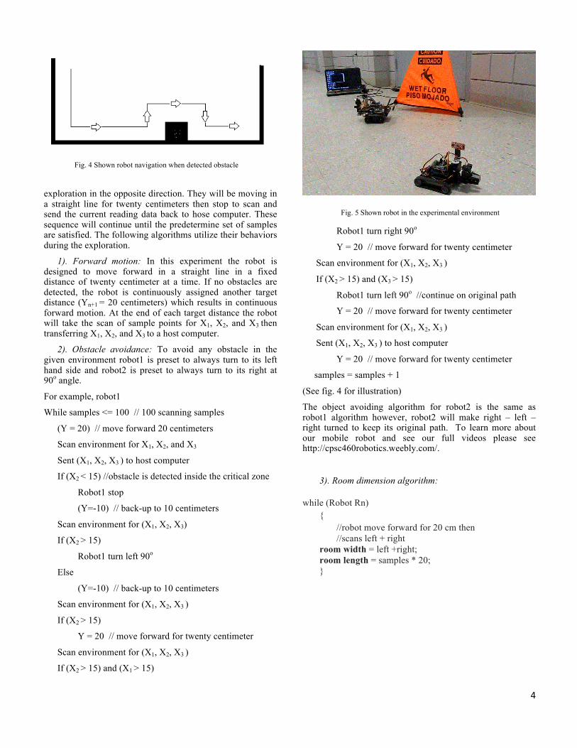
2). Obstacle avoidance: To avoid any obstacle in the given environment robot1 is preset to always turn to its left hand side and robot2 is preset to always turn to its right at 90o angle.
For example, robot1
While samples <= 100 // 100 scanning samples
(Y = 20) // move forward 20 centimeters
Scan environment for X1, X2, and X3
Sent (X1, X2, X3 ) to host computer
If (X2 < 15) //obstacle is detected inside the critical zone
Robot1 stop
(Y=-10) // back-up to 10 centimeters
Scan environment for (X1, X2, X3)
If (X2 > 15)
Robot1 turn left 90o
Else
(Y=-10) // back-up to 10 centimeters
Scan environment for (X1, X2, X3 )
If (X2 > 15)
Y = 20 // move forward for twenty centimeter
Scan environment for (X1, X2, X3 )
If (X2 > 15) and (X1 > 15)
Robot1 turn right 90o
Y = 20 // move forward for twenty centimeter
Scan environment for (X1, X2, X3 )
If (X2 > 15) and (X3 > 15)
Robot1 turn left 90o //continue on original path
Y = 20 // move forward for twenty centimeter
Scan environment for (X1, X2, X3 )
Sent (X1, X2, X3 ) to host computer
Y = 20 // move forward for twenty centimeter
samples = samples + 1
(See fig. 4 for illustration)
The object avoiding algorithm for robot2 is the same as robot1 algorithm however, robot2 will make right – left – right turned to keep its original path. To learn more about our mobile robot and see our full videos please see http://cpsc460robotics.weebly.com/.
3). Room dimension algorithm:
while (Robot Rn) {
//robot move forward for 20 cm then //scans left + right
room width = left +right; room length = samples * 20; }
Fig. 4 Shown robot navigation when detected obstacle
Fig. 5 Shown robot in the experimental environment

5
B. Communication Communication with the host computer is essential in this
experiment. The robot must maintain the communication link to the host computer at all time. Transmission of data(X1, X2,and X3) from the exploration robot is to be transmitted at the end of each scanning for every target distance of twenty centimeter. When implementing multiple robots we employed start system clock command to initiate internal clocks which enable a robot to transmit its data one at a time (See fig. 7).
Communication to base station algorithm:
If multiple robots are used
Enable system clock each cycle 100 milliseconds (see fig. 4)
1st clock cycle enable transmission from robot 1
2nd clock cycle enable transmission from robot 2
3rd clock cycle enable transmission from robot 3
The system clock is continuously running to allow data transmission from each robot to the host computer until the end of exploration.
V. EXPERIMENTAL RESULTS All the methods presented in this paper have been tested
on our mobile robots in the laboratory environment. The environment we tested is about 3m x 4.5m in size, and has some boxes and a laptop computer scattering on one end and enclose with walls on three other sides (see fig. 5).
The first task is to test each of our robot the capabilities to perform forward motions, obstacle avoidance, and communication between the robots to host computer. On this test, similar problems were discovered on both robots. When moving in forward direction they moved off course to its left. Some adjustments were made to reduce the robots wheels friction. However the obstacle avoidance and communication are working as expected.
Second task is to test each robot in the same setup environment as above for its full capabilities. When we started the experiment our robot moved forward for twenty centimeters, scanned for data, transfers data to host computer. These steps were repeated until the set up environment was completely covered. At the completion of the exploration a mobile robot makes 70 stop and scanned its
Fig. 6 Internal clock to enable data transferring from each robot
Fig. 7 Data received on host computer
Fig. 8 Show robot 1 and 2 sensor data stored in host computer

6
surrounding. The data received from a mobile robot were stored on a host computer data base. This information then retrieves and used to plot a 2D map as show on fig. 9.
Third task is to test both mobile robots in the same setup environment as above for their full capabilities. When started the experiment each robot performed their task the same as second experiment. However, robot2 made the turned unexpectedly. This resulted in partial unexplored area in the given environment. If both of the robots are working as expected the total times to complete the exploration would be reduce to half of the single robot used in exploration. The data received from each mobile robots stored on a host computer for the third test (see fig. 8) were plotted on a 2D map as show on fig. 10.
VI. CONCLUSIONS We have introduced a system which included mobile
robots and a host computer. The system is capable of objects
avoidance, measuring distances with its surrounding, and maintaining database for further map building. We have tested our robots system in partial corridor environment. The transmission of data from the robots to the host computer is working as expected (see fig. 7), as well as our robots objects avoidances capability. However the actual distances compared to measured distances are not exactly the same. The inaccurate in measured data may have been contributed from system noise, the speed of the servo-based pan system, and the vibration associated with the ways servo system move. Other problems are the wheels slipping and wheels friction which contributed to the robots off course movement behavior.
REFERENCES [1] O. Wulf and B. Wagner, "Fast 3D scanning methods for laser
measurement systems," in International conference on control systems and computer science (CSCS14), 2003, pp. 2-5.
[2] M. Tomono, "Building an object map for mobile robots using LRF scan matching and vision-based object recognition," in Robotics and Automation, 2004. Proceedings. ICRA'04. 2004 IEEE International Conference on, 2004, pp. 3765-3770.
[3] T. Bailey, J. Nieto, J. Guivant, M. Stevens, and E. Nebot, "Consistency of the EKF-SLAM algorithm," in Intelligent Robots and Systems, 2006 IEEE/RSJ International Conference on, 2006, pp. 3562-3568.
[4] K. B. Sarachik, "Characterising an indoor environment with a mobile robot and uncalibrated stereo," in Robotics and Automation, 1989. Proceedings., 1989 IEEE International Conference on, 1989, pp. 984-989.
[5] I. Jebari, S. Bazeille, E. Battesti, H. Tekaya, M. Klein, A. Tapus, et al., "Multi-sensor semantic mapping and exploration of indoor environments," in Technologies for Practical Robot Applications (TePRA), 2011 IEEE Conference on, 2011, pp. 151-156.
[6] B. Yamauchi, A. Schultz, and W. Adams, "Mobile robot exploration and map-building with continuous localization," in Robotics and Automation, 1998. Proceedings. 1998 IEEE International Conference on, 1998, pp. 3715-3720.
[7] G. M. Youngblood, L. B. Holder, and D. J. Cook, "A framework for autonomous mobile robot exploration and map learning through the use of place-centric occupancy grids," in Proc. of the Machine Learning Workshop on Learning From Spatial Information, 2000, pp. 25-27.
[8] R. Simmons, D. Apfelbaum, W. Burgard, D. Fox, M. Moors, S. Thrun, et al., "Coordination for multi-robot exploration and mapping," in AAAI/IAAI, 2000, pp. 852-858.
[9] Z. Wei, G. Huang, and P. Wang, "The Research on Multi-robot Simultaneous Localization Mapping Algorithm," in Automation and Logistics, 2007 IEEE International Conference on, 2007, pp. 1241-1246.
[10] R. Pandey, A. K. Singh, and K. M. Krishna, "Multi-robot exploration with communication requirement to a moving base station," in Automation Science and Engineering (CASE), 2012 IEEE International Conference on, 2012, pp. 823-828.
Fig. 9 Show 2D map generated from single robot sensor data
Fig. 10 Show 2D map generated from robot1 (in black) robot2 (in green) sensor data