mobile robot kinematics - eth zürich · autonomous mobile robots roland siegwart, margarita chli,...
TRANSCRIPT

|Autonomous Mobile RobotsRoland Siegwart, Margarita Chli, Martin Rufli
ASLAutonomous Systems Lab
Roland Siegwart, Margarita Chli, Martin Rufli
Mobile Robot Kinematics - add ons 1
Mobile Robot KinematicsAutonomous Mobile Robots
Spring 2017

|Autonomous Mobile RobotsRoland Siegwart, Margarita Chli, Martin Rufli
ASLAutonomous Systems Lab
Manipulator arms versus mobile robots Robot arms are fixed to the ground and usually comprised of a single chain of actuated links The motion of mobile robots is defined through rolling and sliding constraints taking effect at
the wheel-ground contact points
Mobile Robot Kinematics - add ons 2
Mobile Robot Kinematics: Overview
C Willow GarageRide an ABB, https://www.youtube.com/watch?v=bxbjZiKAZP4

|Autonomous Mobile RobotsRoland Siegwart, Margarita Chli, Martin Rufli
ASLAutonomous Systems Lab
Manipulator arms versus mobile robots Both are concerned with forward and inverse kinematics However, for mobile robots, encoder values don‘t map to unique robot poses However, mobile robots can move unbound with respect to their environment There is no direct (=instantaneous) way to measure the robot’s position Position must be integrated over time, depends on path taken Leads to inaccuracies of the position (motion) estimate
Understanding mobile robot motion starts with understanding wheel constraints placed on the robot’s mobility
Mobile Robot Kinematics - add ons 3
Mobile Robot Kinematics: Overview

|Autonomous Mobile RobotsRoland Siegwart, Margarita Chli, Martin Rufli
ASLAutonomous Systems Lab
Non-holonomic systems differential equations are not integrable to the final position. the measure of the traveled distance of each wheel is not sufficient to calculate the final
position of the robot. One has also to know how this movement was executed as a function of time.
This is in stark contrast to actuator arms
Mobile Robot Kinematics - add ons 4
Non-Holonomic Systems
2121
212121
,,,
yyxxssssss LLRR
s1L s1R
s2L
s2R
yI
xI
x1, y1
x2, y2
s1
s2

|Autonomous Mobile RobotsRoland Siegwart, Margarita Chli, Martin Rufli
ASLAutonomous Systems Lab
Forward kinematics: Transformation from joint to physical space
Inverse kinematics Transformation from physical to joint space Required for motion control
Due to non-holonomic constraints in mobile robotics, we deal with differential (inverse) kinematics Transformation between velocities instead of positions Such a differential kinematic model of a robot has the following form:
Mobile Robot Kinematics - add ons 5
Forward and Inverse Kinematics
(nonintegrable) Robot Model
(x,y,theta)(v, omega)-
Control law

|Autonomous Mobile RobotsRoland Siegwart, Margarita Chli, Martin Rufli
ASLAutonomous Systems Lab
Wheels are the most appropriate solution for most applications
Three wheels are sufficient to guarantee stability
With more than three wheels an appropriate suspension is required
Selection of wheels depends on the application
Locomotion Concepts - add ons 6
Mobile Robots with Wheels

|Autonomous Mobile RobotsRoland Siegwart, Margarita Chli, Martin Rufli
ASLAutonomous Systems Lab
a) Standard wheel: Two degrees of freedom; rotation around the (motorized) wheel axle and the contact point
b) Castor wheel: Three degrees of freedom; rotation around the wheel axle, the contact point and the castor axle
Locomotion Concepts - add ons 7
The Four Basic Wheels Types

|Autonomous Mobile RobotsRoland Siegwart, Margarita Chli, Martin Rufli
ASLAutonomous Systems Lab
c) Swedish wheel: Three degrees of freedom; rotation around the (motorized) wheel axle, around the rollers and around the contact point
d) Ball or spherical wheel: Suspension technically not solved
Locomotion Concepts - add ons 8
The Four Basic Wheels Types

|Autonomous Mobile RobotsRoland Siegwart, Margarita Chli, Martin Rufli
ASLAutonomous Systems Lab
Stability of a vehicle is be guaranteed with 3 wheels If center of gravity is within the triangle which is formed by the ground contact point of the
wheels. Stability is improved by 4 and more wheel however, this arrangements are hyper static and require a flexible suspension system.
Bigger wheels allow to overcome higher obstacles but they require higher torque or reductions in the gear box.
Most arrangements are non-holonomic (see chapter 3) require high control effort
Combining actuation and steering on one wheel makes the design complex and adds additional errors for odometry.
Locomotion Concepts - add ons 9
Characteristics of Wheeled Robots and Vehicles

|Autonomous Mobile RobotsRoland Siegwart, Margarita Chli, Martin Rufli
ASLAutonomous Systems Lab
Locomotion Concepts - add ons 10
Different Arrangements of Wheels I
Two wheels
Three wheels
Omnidirectional Drive Synchro Drive
COG below axle
|Autonomous Mobile RobotsRoland Siegwart, Margarita Chli, Martin Rufli
ASLAutonomous Systems Lab
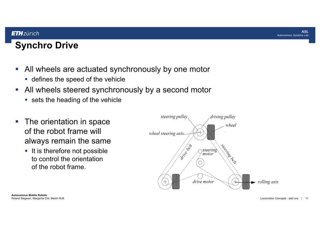
All wheels are actuated synchronously by one motor defines the speed of the vehicle
All wheels steered synchronously by a second motor sets the heading of the vehicle
The orientation in spaceof the robot frame will always remain the same It is therefore not possible
to control the orientation of the robot frame.
Locomotion Concepts - add ons 11
Synchro Drive

|Autonomous Mobile RobotsRoland Siegwart, Margarita Chli, Martin Rufli
ASLAutonomous Systems Lab
Four wheels
Six wheels
Locomotion Concepts - add ons 12
Different Arrangements of Wheels II

|Autonomous Mobile RobotsRoland Siegwart, Margarita Chli, Martin Rufli
ASLAutonomous Systems Lab
Four powered castor wheels with active steering Results in omni-drive-like behaviour Results in simplified high-level planning (see chapter 6)
Locomotion Concepts - add ons 213
Case Study: Willow Garage‘s PR2
C W
illow
Gar
age

|Autonomous Mobile RobotsRoland Siegwart, Margarita Chli, Martin Rufli
ASLAutonomous Systems Lab
Movement in the plane has 3 DOF thus only three wheels can be independently
controlled It might be better to
arrange three swedishwheels in a triangle
Locomotion Concepts - add ons 14
CMU Uranus: Omnidirectional Drive with 4 Wheels
|Autonomous Mobile RobotsRoland Siegwart, Margarita Chli, Martin Rufli
ASLAutonomous Systems Lab
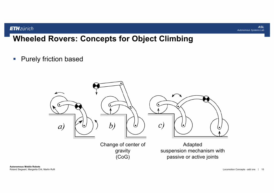
Purely friction based
Locomotion Concepts - add ons 15
Wheeled Rovers: Concepts for Object Climbing
Change of center of gravity(CoG)
Adapted suspension mechanism with
passive or active joints

|Autonomous Mobile RobotsRoland Siegwart, Margarita Chli, Martin Rufli
ASLAutonomous Systems Lab
Passive locomotion concept 6 wheels two boogies on each side fixed wheel in the rear front wheel with spring
suspension Dimensions length: 60 cm height: 20 cm
Characteristics highly stable in rough terrain overcomes obstacles up to
2 times its wheel diameter
Locomotion Concepts - add ons 16
Climbing with Legs: Shrimp (ASL EPFL/ETH)

|Autonomous Mobile RobotsRoland Siegwart, Margarita Chli, Martin Rufli
ASLAutonomous Systems Lab
Mobile Robot Kinematics - add ons 17
Kinematic Constraints: Fixed Standard Wheel
y.
x.
. v = r .

|Autonomous Mobile RobotsRoland Siegwart, Margarita Chli, Martin Rufli
ASLAutonomous Systems Lab
Mobile Robot Kinematics - add ons 18
3 - Mobile Robot Kinematics
l
Robot chassis
TR yx
v = r .
x.
x sin.
x cos.
A
.
y
.
y (cos
.
y sin
.
l).
(l)sin.
l)cos.

|Autonomous Mobile RobotsRoland Siegwart, Margarita Chli, Martin Rufli
ASLAutonomous Systems Lab
Suppose that the wheel A is in position such that = 0 and = 0 This would place the contact point of the wheel on XI with the plane of the
wheel oriented parallel to YI. If = 0, then the sliding constraint reduces to:
Mobile Robot Kinematics - add ons 19
Example

|Autonomous Mobile RobotsRoland Siegwart, Margarita Chli, Martin Rufli
ASLAutonomous Systems Lab
Mobile Robot Kinematics - add ons 20
Kinematic Constraints:

|Autonomous Mobile RobotsRoland Siegwart, Margarita Chli, Martin Rufli
ASLAutonomous Systems Lab
Given a robot with M wheels each wheel imposes zero or more constraints on the robot motion only fixed and steerable standard wheels impose constraints
Suppose we have a total of N=Nf + Ns standard wheels We can develop the equations for the constraints in matrix forms: Rolling
Lateral movement
Mobile Robot Kinematics - add ons 21
Kinematic Constraints: Complete Robot
0)()( 21 JRJ Is
1 )()(
)(
sf NNs
f
tt
t
3 1
11 )(
)(
sf NNss
fs J
JJ
)( 12 NrrdiagJ
3 1
11 )(
)(
sf NNss
fs C
CC
0)()(1 Is RC

|Autonomous Mobile RobotsRoland Siegwart, Margarita Chli, Martin Rufli
ASLAutonomous Systems Lab
The maneuverability of a mobile robot is the combination of the mobility available based on the sliding constraints plus additional freedom contributed by the steering
Three wheels is sufficient for static stability additional wheels need to be synchronized this is also the case for some arrangements with three wheels
It can be derived using the equation seen before Degree of mobility Degree of steerability Robots maneuverability
Mobile Robot Kinematics - add ons 22
Mobile Robot Maneuverability
m
s
smM

|Autonomous Mobile RobotsRoland Siegwart, Margarita Chli, Martin Rufli
ASLAutonomous Systems Lab
To avoid any lateral slip the motion vector has to satisfy the following constraints:
Mathematically: must belong to the null space of the projection matrix
Null space of is the space N such that for any vector n in N
Geometrically this can be shown by the Instantaneous Center of Rotation (ICR)
Mobile Robot Kinematics - add ons 23
Mobile Robot Maneuverability: Degree of Mobility
0)()(1 Iss RC
0)(1 If RC
)()(
1
11
ss
fs C
CC
IR )( )(1 sC
)(1 sC
0)(1 nC s
IR )(

|Autonomous Mobile RobotsRoland Siegwart, Margarita Chli, Martin Rufli
ASLAutonomous Systems Lab
Instantaneous center of rotation (ICR)
Ackermann Steering Bicycle
Mobile Robot Kinematics - add ons 24
Mobile Robot Maneuverability: ICR

|Autonomous Mobile RobotsRoland Siegwart, Margarita Chli, Martin Rufli
ASLAutonomous Systems Lab
Robot chassis kinematics is a function of the set of independent constraints
the greater the rank of the more constrained is the mobility
Mathematically no standard wheels all direction constrained
Examples: Unicycle: One single fixed standard wheel Differential drive: Two fixed standard wheels wheels on same axle wheels on different axle
Mobile Robot Kinematics - add ons 25
Mobile Robot Maneuverability: More on Degree of Mobility
)( 1 sCrank
)()(
1
11
ss
fs C
CC
0)()(1 Iss RC
0)(1 If RC
)(1 sC )( 3)( dim 11 ssm CrankCN
3)( 1 sCrank 0)( 1 sCrank
3)( 0 1 sCrank

|Autonomous Mobile RobotsRoland Siegwart, Margarita Chli, Martin Rufli
ASLAutonomous Systems Lab
Indirect degree of motion
The particular orientation at any instant imposes a kinematic constraint However, the ability to change that orientation can lead additional degree of maneuverability
Range of :
Examples: one steered wheel: Tricycle two steered wheels: No fixed standard wheel car (Ackermann steering): Nf = 2, Ns=2 -> common axle
Mobile Robot Kinematics - add ons 26
Mobile Robot Maneuverability: Degree of Steerability
)( 1 sss Crank
20 ss

|Autonomous Mobile RobotsRoland Siegwart, Margarita Chli, Martin Rufli
ASLAutonomous Systems Lab
Degree of Maneuverability
Two robots with same are not necessary equal Example: Differential drive and Tricycle (next slide)
For any robot with the ICR is always constrained to lie on a line
For any robot with the ICR is not constrained and can be set to any point on the plane
The Synchro Drive example:
Mobile Robot Kinematics - add ons 27
Mobile Robot Maneuverability: Robot Maneuverability
smM
2M
3M
211 smM
M C J. Borenstein

|Autonomous Mobile RobotsRoland Siegwart, Margarita Chli, Martin Rufli
ASLAutonomous Systems Lab
Mobile Robot Kinematics - add ons 28
Five Basic Types of Three-Wheel Configurations

|Autonomous Mobile RobotsRoland Siegwart, Margarita Chli, Martin Rufli
ASLAutonomous Systems Lab
The objective of a kinematic controller is to follow a trajectory described by its position and/or velocity profiles as function of time.
Motion control is not straight forward because mobile robots are typically non-holonomic and MIMO systems.
Most controllers (including the one presented here) are not considering the dynamics of the system
Mobile Robot Kinematics - add ons 29
Wheeled Mobile Robot Motion Control: Overview

|Autonomous Mobile RobotsRoland Siegwart, Margarita Chli, Martin Rufli
ASLAutonomous Systems Lab
Trajectory (path) divided in motion segments of clearly Defined shape: straight lines and segments of a circle Dubins car, and Reeds-Shepp car
Control problem: pre-compute a smooth trajectory
based on line, circle (and clothoid) segments Disadvantages: It is not at all an easy task to pre-compute a feasible trajectory limitations and constraints of the robots velocities and accelerations does not adapt or correct the trajectory if dynamical changes
of the environment occur. The resulting trajectories are usually not smooth (in acceleration, jerk, etc.)
Mobile Robot Kinematics - add ons 30
Motion Control: Open Loop ControlyI
xI
goal

|Autonomous Mobile RobotsRoland Siegwart, Margarita Chli, Martin Rufli
ASLAutonomous Systems Lab
Find a control matrix K, if exists
with kij=k(t,e) such that the control of v(t) and (t)
drives the error e to zero
MIMO state feedback control
Mobile Robot Kinematics - add ons 31
Motion Control: Feedback Control
232221
131211
kkkkkk
K
yx
KeKttv
R
)()(
0)(lim
tet
yR
xR
goal
v(t)
(t)
start e
(nonintegrable) Robot Model
(x,y,theta)(v, omega)-
Control law

|Autonomous Mobile RobotsRoland Siegwart, Margarita Chli, Martin Rufli
ASLAutonomous Systems Lab
The kinematics of a differential drive mobile robot described in the inertial frame {xI, yI, } is given by,
where and are the linear velocities in the direction of the xI and yI of the inertial frame.
Let alpha denote the angle between the xR axis of the robots reference frame and the vector connecting the center of the axle of the wheels with the final position.
Mobile Robot Kinematics - add ons 32
Motion Control: Kinematic Position Control
y
vsincos
yxI
1000
x y

|Autonomous Mobile RobotsRoland Siegwart, Margarita Chli, Martin Rufli
ASLAutonomous Systems Lab
y
Coordinates transformation into polar coordinates with its origin at goal position:
System description, in the new polar coordinates
Mobile Robot Kinematics - add ons 33
Kinematic Position Control: Coordinates Transformation
for for

|Autonomous Mobile RobotsRoland Siegwart, Margarita Chli, Martin Rufli
ASLAutonomous Systems Lab
y
The coordinates transformation is not defined at x = y = 0;
For the forward direction of the robot points toward the goal, for it is the backward direction.
By properly defining the forward direction of the robot at its initial configuration, it is always possible to have at t=0. However this does not mean that remains in I1 for all time t.
Mobile Robot Kinematics - add ons 34
Kinematic Position Control: Remarks

|Autonomous Mobile RobotsRoland Siegwart, Margarita Chli, Martin Rufli
ASLAutonomous Systems Lab
y
It can be shown, that with
the feedback controlled system
will drive the robot to The control signal v has always constant sign, the direction of movement is kept positive or negative during movement parking maneuver is performed always in the most natural way and without ever inverting its
motion.
Mobile Robot Kinematics - add ons 35
Kinematic Position Control: The Control Law
000 ,,,,

|Autonomous Mobile RobotsRoland Siegwart, Margarita Chli, Martin Rufli
ASLAutonomous Systems Lab
The goal is in the center and the initial position on the circle.
Mobile Robot Kinematics - add ons 36
Kinematic Position Control: Resulting Path
1.5)(3,8,)βk,αk,ρ(kk