mobile and sensor systems lecture 2: mobile medium …cm542/teaching/2010/mobile-pdfs/mobile... ·...
TRANSCRIPT

Mobile and Sensor Systems
Lecture 2: Mobile Medium Access
Control Layer""Dr. Cecilia Mascolo"
"

In this Lecture"
• In this lecture we will discuss aspects related to the MAC Layer of wireless networks "
– In comparison with wired networks"– In terms of how multiplexing in applied"– In terms of carrier sensing"
Access methods SDMA/FDMA/TDMA"
• SDMA (Space Division Multiple Access)"– segment space into sectors, use directed antennas "– cell structure"
• FDMA (Frequency Division Multiple Access)"– assign a certain frequency to a transmission channel between a
sender and a receiver"– permanent (e.g., radio broadcast), slow hopping (e.g., GSM),
fast hopping (FHSS, Frequency Hopping Spread Spectrum)"• TDMA (Time Division Multiple Access)"
– assign the fixed sending frequency to a transmission channel between a sender and a receiver for a certain amount of time"
• The multiplexing schemes presented in the previous lecture are now used to control medium access! "

FDM in GSM"
f
t
124
1
124
1
20 MHz
200 kHz
890.2 MHz
935.2 MHz
915 MHz
960 MHz
FDD/FDMA -‐ general scheme, example GSM

TDMA in DECT"
1 2 3 11 12 1 2 3 11 12
t downlink uplink
417 µs

Access method CDMA"• CDMA (Code Division Multiple Access)"
– all terminals send on the same frequency roughly at the same time and can use the whole bandwidth of the transmission channel "
– each sender has a unique random number, the sender XORs the signal with this random number"
– the receiver can “tune” into this signal if it knows the random number, tuning is done via a correlation function"
• Disadvantages:"– higher complexity of a receiver (receiver cannot just listen into
the medium and start receiving if there is a signal)"– all signals should have the same strength at a receiver"
• Advantages: "– all terminals can use the same frequency, no planning needed"– huge code space (e.g. 232) compared to frequency space"

CDMA in theory"• Sender A "
– sends Ad = 1, key Ak = 010011 (assign: “0”= -1, “1”= +1)"– sending signal As = Ad * Ak = (-1, +1, -1, -1, +1, +1)"
• Sender B"– sends Bd = 0, key Bk = 110101 (assign: “0”= -1, “1”= +1)"– sending signal Bs = Bd * Bk = (-1, -1, +1, -1, +1, -1)"
• Both signals superimpose in space "– interference neglected (noise etc.)"– As + Bs = (-2, 0, 0, -2, +2, 0)"
• Receiver wants to receive signal from sender A"– apply key Ak bitwise (inner product)"
• Ae = (-2, 0, 0, -2, +2, 0) • Ak = 2 + 0 + 0 + 2 + 2 + 0 = 6"• result greater than 0, therefore, original bit was “1” "
– receiving B"• Be = (-2, 0, 0, -2, +2, 0) • Bk = -2 + 0 + 0 - 2 - 2 + 0 = -6, i.e. “0”"

CDMA on signal level I"data A
key A
signal A
data ⊕ key
key
1" 0" 1"
1"0" 0" 1" 0" 0" 1" 0" 0" 0" 1" 0" 1" 1" 0" 0" 1" 1"0"1" 1" 0" 1" 1" 1" 0" 0" 0" 1" 0" 0" 0" 1" 1" 0" 0"
Ad"
Ak"
As"
0 is a posi:ve signal and 1 is a nega:ve signal in these examples
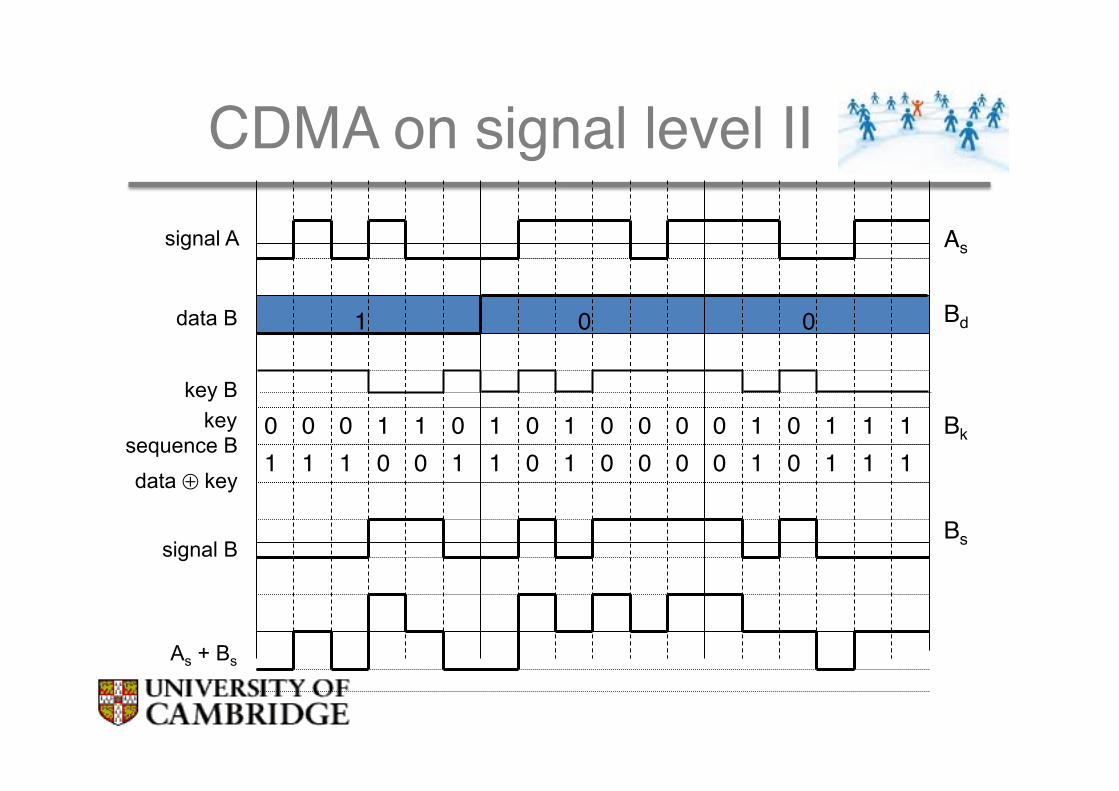
CDMA on signal level II"signal A
data B
key B key
sequence B
signal B
As + Bs
data ⊕ key
1" 0" 0"
0"0" 0" 1" 1" 0" 1" 0" 1" 0" 0" 0" 0" 1" 0" 1" 1" 1"1"1" 1" 0" 0" 1" 1" 0" 1" 0" 0" 0" 0" 1" 0" 1" 1" 1"
Bd"
Bk"
Bs"
As"

CDMA on signal level III"
Ak
(As + Bs) * Ak
Integrator output
Comparator output
As + Bs
data A
1" 0" 1"
1" 0" 1" Ad"

CDMA on signal level IV"
Integrator output
Comparator output
Bk
(As + Bs) * Bk
As + Bs
data B
1" 0" 0"
1" 0" 0" Bd"

comparator output
CDMA on signal level V"
wrong key K
integrator output
(As + Bs) * K
As + Bs
(0)" (0)" ?"

Comparisons"Approach SDMA TDMA FDMA CDMAIdea segment space into
cells/sectorssegment sendingtime into disjointtime-slots, demanddriven or fixedpatterns
segment thefrequency band intodisjoint sub-bands
spread the spectrumusing orthogonal codes
Terminals only one terminal canbe active in onecell/one sector
all terminals areactive for shortperiods of time onthe same frequency
every terminal has itsown frequency,uninterrupted
all terminals can be activeat the same place at thesame moment,uninterrupted
Signalseparation
cell structure, directedantennas
synchronization inthe time domain
filtering in thefrequency domain
code plus specialreceivers
Advantages very simple, increasescapacity per km²
established, fullydigital, flexible
simple, established,robust
flexible, less frequencyplanning needed, softhandover
Dis-advantages
inflexible, antennastypically fixed
guard spaceneeded (multipathpropagation),synchronizationdifficult
inflexible,frequencies are ascarce resource
complex receivers, needsmore complicated powercontrol for senders
Comment only in combinationwith TDMA, FDMA orCDMA useful
standard in fixednetworks, togetherwith FDMA/SDMAused in manymobile networks
typically combinedwith TDMA(frequency hoppingpatterns) and SDMA(frequency reuse)
still faces some problems,higher complexity,lowered expectations; willbe integrated withTDMA/FDMA

• Multiplexing is one way to allow a basic share of medium to be shared more efficiently through the definition of “channels”"
• Once channels are established packets will be sent through that"– Might be a bit rigid as a method"– For example, frequency division multiplexing would have issues
with large numbers of users."– Also depending on traffic and time some users might want to
send more or less"
• More ad hoc approaches exist which allow channels to be shared in a “statistical” way"
Limitations of multiplexing"
Review: Ethernet Medium Access Control (MAC)"
• In Ethernet based fixed networks where you have wires between computers:"
• CS (Carrier Sense): listen for othersʼ transmissions before transmitting; defer to others you hear"
• CD (Collision Detection): as you transmit, listen and verify you hear exactly what you send; if not, back off random interval, within exponentially longer range each time you transmit unsuccessfully!
!!Can CD be applied on wireless networks?!

Can we apply the same MAC protocols in wireless?"
• Problems in wireless networks"– signal strength decreases proportionally to the square of the
distance"– the sender would apply CS and CD, but collisions happen at the
receiver"– it might be the case that a sender cannot “hear” the collision, i.e.,
CD does not work"– furthermore, CS might not work if, e.g., a terminal is “hidden”"
"

CSMA/CA: Carrier Sensing Multiple Access Protocol with Collision Avoidance"
19
CS/ECE 438 © Robin Kravets, UIUC - Spring 2007 37
Interframe Spacing
! Interframe spacing " Plays a large role in coordinating access to the
transmission medium
! Varying interframe spacings" Creates different priority levels for different types of traffic!
! 802.11 uses 4 different interframe spacings
t
medium busySIFS
PIFS
DIFSDIFS
next framecontention
direct access if
medium is free ! DIFS
CS/ECE 438 © Robin Kravets, UIUC - Spring 2007 38
IEEE 802.11 - CSMA/CA
! Sensing the medium
! If free for an Inter-Frame Space (IFS)" Station can start sending (IFS depends on service type)
! If busy" Station waits for a free IFS, then waits a random back-off time
(collision avoidance, multiple of slot-time)
! If another station transmits during back-off time " The back-off timer stops (fairness)
t
medium busy
DIFSDIFS
next frame
contention window
(randomized back-off
mechanism)
slot timedirect access if
medium is free ! DIFS
• CSMA/CA: sense medium. If free transmit (although this might generate collision at the receiver). If not, wait with a back off strategy. Transmit when medium is sensed free.

• Hidden terminals"– A sends to B, C cannot receive from A "– C wants to send to B, C senses a “free” medium (CS fails)"– Collision at B, A cannot receive the collision (CD fails)"– A is “hidden” for C "
Hidden Terminal"
B A C
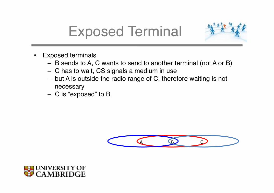
Exposed Terminal"• Exposed terminals"
– B sends to A, C wants to send to another terminal (not A or B)"– C has to wait, CS signals a medium in use"– but A is outside the radio range of C, therefore waiting is not
necessary"– C is “exposed” to B"
B A C

Multiple Access with Collision Avoidance (for Wireless): MACA(W))"
• Sender B asks receiver C whether C is able to receive a transmission Request to Send (RTS)!
• Receiver C agrees, sends out a Clear to Send (CTS)"
• Potential interferers overhear either RTS or CTS and know about impending transmission and for how long it will last"– Store this information in a
Network Allocation Vector"• B sends, C acks" ! MACA(W) protocol (used e.g. in
IEEE 802.11)"
A B C D
RTS
CTS
Data
Ack
NAV indicates busy medium
NAV indicates busy medium
MACA(W) "
• Absent CTS, sender backs off exponentially before retrying"• RTS and CTS can still themselves collide at their receivers; less
chance as theyʼre short; "
• Whatʼs the effect on exposed terminal problem?!

RTS/CTS "• RTS/CTS ameliorate, but do not solve hidden/exposed terminal
problems"• Example problem cases: "
A B C D
RTS
CTS
Data
A B C D
RTS
RTS
CTS
RTS
RTSCTS
CTSData
Data
Ack

The 802.11 Protocol"
• 802.11 uses 2 modes of operation: a basic CSMA/CA (in base station mode) and the RTS/CTS mode."
• Generally 802.11 drivers leave the RTS/CTS off by default."
• Also tests in practice show that hidden terminal might not be a problem in most cases as interference range is more than double communication range. Consider A->B<-C when A transmits it is very likely C can sense Aʼs carrier directly."
Summary"
• We have shown how multiplexing can be used at the MAC layer"
• We have explained the limits of carrier sensing "
• We have described the problems related to “hidden and exposed” terminals"