mobile ad hoc networks 1
TRANSCRIPT
1Mobile Ad Hoc NetworksAsis Nasipuri
Department of Electrical & Computer EngineeringThe University of North Carolina at Charlotte
Charlotte, NC 28223-0001
I. I NTRODUCTION
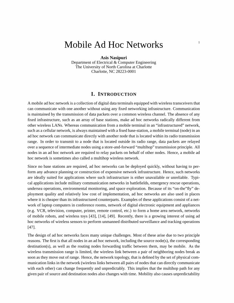
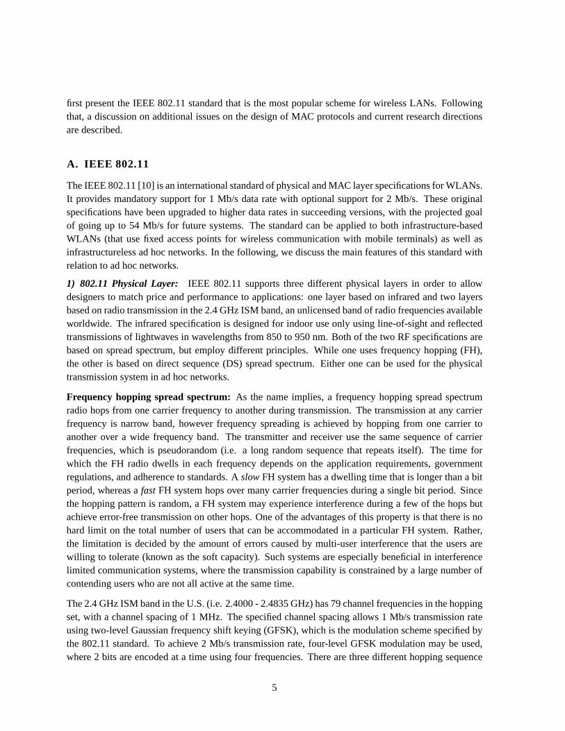
A mobile ad hoc network is a collection of digital data terminals equipped with wireless transceivers thatcan communicate with one another without using any fixed networking infrastructure. Communicationis maintained by the transmission of data packets over a common wireless channel. The absence of anyfixed infrastructure, such as an array of base stations, make ad hoc networks radically different fromother wireless LANs. Whereas communication from a mobile terminal in an “infrastructured” network,such as a cellular network, is always maintained with a fixed base-station, a mobile terminal (node) in anad hoc network can communicate directly with another node that is located within its radio transmissionrange. In order to transmit to a node that is located outside its radio range, data packets are relayedover a sequence of intermediate nodes using a store-and-forward “multihop” transmission principle. Allnodes in an ad hoc network are required to relay packets on behalf of other nodes. Hence, a mobile adhoc network is sometimes also called a multihop wireless network.
Since no base stations are required, ad hoc networks can be deployed quickly, without having to per-form any advance planning or construction of expensive network infrastructure. Hence, such networksare ideally suited for applications where such infrastructure is either unavailable or unreliable. Typi-cal applications include military communication networks in battlefields, emergency rescue operations,undersea operations, environmental monitoring, and space exploration. Because of its “on-the”fly” de-ployment quality and relatively low cost of implementation, ad hoc networks are also used in placeswhere it is cheaper than its infrastructured counterparts. Examples of these applications consist of a net-work of laptop computers in conference rooms, network of digital electronic equipment and appliances(e.g. VCR, television, computer, printer, remote control, etc.) to form a home area network, networksof mobile robots, and wireless toys [43], [14], [49]. Recently, there is a growing interest of using adhoc networks of wireless sensors to perform unmanned distributed surveillance and tracking operations[47].
The design of ad hoc networks faces many unique challenges. Most of these arise due to two principlereasons. The first is that all nodes in an ad hoc network, including the source node(s), the correspondingdestination(s), as well as the routing nodes forwarding traffic between them, may be mobile. As thewireless transmission range is limited, the wireless link between a pair of neighboring nodes break assoon as they move out of range. Hence, the network topology, that is defined by the set of physical com-munication links in the network (wireless links between all pairs of nodes that can directly communicatewith each other) can change frequently and unpredictably. This implies that the multihop path for anygiven pair of source and destination nodes also changes with time. Mobility also causes unpredictability
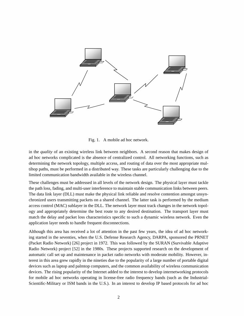
Fig. 1. A mobile ad hoc network.
in the quality of an existing wireless link between neighbors. A second reason that makes design ofad hoc networks complicated is the absence of centralized control. All networking functions, such asdetermining the network topology, multiple access, and routing of data over the most appropriate mul-tihop paths, must be performed in a distributed way. These tasks are particularly challenging due to thelimited communication bandwidth available in the wireless channel.
These challenges must be addressed in all levels of the network design. The physical layer must tacklethe path loss, fading, and multi-user interference to maintain stable communication links between peers.The data link layer (DLL) must make the physical link reliable and resolve contention amongst unsyn-chronized users transmitting packets on a shared channel. The latter task is performed by the mediumaccess control (MAC) sublayer in the DLL. The network layer must track changes in the network topol-ogy and appropriately determine the best route to any desired destination. The transport layer mustmatch the delay and packet loss characteristics specific to such a dynamic wireless network. Even theapplication layer needs to handle frequent disconnections.
Although this area has received a lot of attention in the past few years, the idea of ad hoc network-ing started in the seventies, when the U.S. Defense Research Agency, DARPA, sponsored the PRNET(Packet Radio Network) [26] project in 1972. This was followed by the SURAN (Survivable AdaptiveRadio Network) project [52] in the 1980s. These projects supported research on the development ofautomatic call set up and maintenance in packet radio networks with moderate mobility. However, in-terest in this area grew rapidly in the nineties due to the popularity of a large number of portable digitaldevices such as laptop and palmtop computers, and the common availability of wireless communicationdevices. The rising popularity of the Internet added to the interest to develop internetworking protocolsfor mobile ad hoc networks operating in license-free radio frequency bands (such as the Industrial-Scientific-Military or ISM bands in the U.S.). In an interest to develop IP based protocols for ad hoc
2
networking, a working group for Mobile Ad Hoc Networking (MANET) was formed within the InternetEngineering Task Force (IETF) [20]. The DoD also renewed their support on similar research objectivesby starting the GloMo (Global Mobile Information Systems) and the NTDR (Near-term Digital Radio)projects. Spurred by the growing interest in ad hoc networking, a number of commercial standardswere developed in the late nineties. This includes the IEEE 802.11 physical layer and MAC protocolin 1995 [10], which has since then evolved into the more updated versions. Today, one can build an adhoc network by simply plugging in 802.11 PCMCIA cards into laptop computers. Bluetooth [13] andHiperlan [53] are some other examples of related existing products. In this chapter we discuss some thekey challenges, protocols, and future directions of mobile ad hoc networks.
II. P HYSICAL L AYER AND MAC
The main aspects of designing the physical transmission system are dependent on the characteristics ofthe radio propagation channel such as path loss, interference (co-channel), and fading. In addition, sincemobile terminals usually have limited power resources, the transceiver must be power efficient. Theseaspects are taken into account while designing the modulation, coding, and power control features inthe radio equipment. In principle, the radio equipment in the nodes forming a mobile ad hoc networkcan use any technology as long as it provides reliable links between neighboring mobile terminals ona common channel. Candidate physical layers that have gained prominence are infrared and spreadspectrum radio.
The MAC plays the key role in determining the channel usage efficiency by resolving contentionamongst a number of unsupervised terminals sharing the common channel. An efficient MAC protocolwould allow the transmissions from independent nodes to be separated in time and space, thereby max-imizing the probability of successful transmissions and maintaining fairness amongst all users. Thoughresearch on medium access schemes for wired local area networks (LANs) have been done for manyyears, the same concepts cannot be directly applied to wireless LANs. In a wired medium, a transmittedsignal is received with the same signal strength at all terminals connected to the same shared medium.Hence a terminal in a LAN can avoid contention by sensing the presence of a carrier to determine if anyother terminal is using the channel before it starts a transmission. This “listen before transmit” prin-ciple has led to a class of efficient random access protocols for wired LANs that are generally knownas carrier sense multiple access (CSMA) schemes [28]. A popular example is CSMA/CD (CSMA withcollision detection), which is the standard for Ethernet (IEEE 802.3) LANs [46].
However, designing MAC protocols for wireless networks faces a different set of challenges. Propaga-tion path losses in the wireless channel cause the signal power to decline with distance. This introducesthe following problems, which are the main factors that affect the efficiency of the MAC in a mobile adhoc network:
• Carrier sensing is location-dependent:Since the strength of the received signal depends on thedistance from the transmitter, the same signal is not heard equally well by all terminals. Hence car-rier sensing is not very effective in wireless. Typical problems of using carrier sensing to determinethe availability of the wireless channel are:
– The hidden terminal problem: a node may be hidden or out of range from a sender but
3
A
C
D
B
A
B
C
D
(a) (b)
Fig. 2. Illistration of the hidden terminal problem (a) and the exposed terminal problem (b). The dottedlines represent the radio ranges.
within range of its intended receiver. For instance, in Figure 2(a), nodeC is out of range fromA, and hence any transmission fromC cannot be heard byA. So whileC is transmitting toB,nodeA thinks that the channel is idle and simultaneously transmits a data packet to nodeB.This causes both packets to be lost atB because of interference, and the packets are consideredto have suffered a “collision”. A transmission fromA to B will face the same consequenceeven ifC is transmitting to some other node, such asD.
– The exposed terminal problem: this is the reverse problem, where a transmitting or “ex-posed” node is within range of a sender, but is out of range of the intended destination. Theproblem is illustrated in Figure 2(b), where nodeB, which wants to transmit a data packet toA, finds the channel to be busy due to the transmission fromC to D. Hence,B might waitfor the transmission fromC to be over before transmitting toA, which is not necessary as thetransmission fromC would not interfere atA.
Both the hidden terminal and the exposed terminal problems arise due to the fact that carrier sensingis only performed at the transmitter, whereas its effect is determined by the interference power atthe receiver, which are usually different due to propagation path loss characteristics.
• Collision detection is not possible: A wireless transceiver cannot transmit and receive at thesame time as the transmitted signal will always be far stronger than any received signal. Hence awireless terminal cannot detect if its transmission has been successful. To inform the transmittingnode about a successful packet transmission, the receiver sends anACKNOWLEDGEMENT (ACK)packet back to the transmitter after it receives a data packet. If the transmitter does not receive anACK within a fixed period of time, it assumes that the transmitted packet has been lost. However,this is learnt only after completing transmission of the data packet and waiting for a further no-ACKtimeout period.
Many different schemes have been designed for reducing these problems in wireless channel access. We
4
first present the IEEE 802.11 standard that is the most popular scheme for wireless LANs. Followingthat, a discussion on additional issues on the design of MAC protocols and current research directionsare described.
A. IEEE 802.11
The IEEE 802.11 [10] is an international standard of physical and MAC layer specifications for WLANs.It provides mandatory support for 1 Mb/s data rate with optional support for 2 Mb/s. These originalspecifications have been upgraded to higher data rates in succeeding versions, with the projected goalof going up to 54 Mb/s for future systems. The standard can be applied to both infrastructure-basedWLANs (that use fixed access points for wireless communication with mobile terminals) as well asinfrastructureless ad hoc networks. In the following, we discuss the main features of this standard withrelation to ad hoc networks.
1) 802.11 Physical Layer: IEEE 802.11 supports three different physical layers in order to allowdesigners to match price and performance to applications: one layer based on infrared and two layersbased on radio transmission in the 2.4 GHz ISM band, an unlicensed band of radio frequencies availableworldwide. The infrared specification is designed for indoor use only using line-of-sight and reflectedtransmissions of lightwaves in wavelengths from 850 to 950 nm. Both of the two RF specifications arebased on spread spectrum, but employ different principles. While one uses frequency hopping (FH),the other is based on direct sequence (DS) spread spectrum. Either one can be used for the physicaltransmission system in ad hoc networks.
Frequency hopping spread spectrum:As the name implies, a frequency hopping spread spectrumradio hops from one carrier frequency to another during transmission. The transmission at any carrierfrequency is narrow band, however frequency spreading is achieved by hopping from one carrier toanother over a wide frequency band. The transmitter and receiver use the same sequence of carrierfrequencies, which is pseudorandom (i.e. a long random sequence that repeats itself). The time forwhich the FH radio dwells in each frequency depends on the application requirements, governmentregulations, and adherence to standards. AslowFH system has a dwelling time that is longer than a bitperiod, whereas afastFH system hops over many carrier frequencies during a single bit period. Sincethe hopping pattern is random, a FH system may experience interference during a few of the hops butachieve error-free transmission on other hops. One of the advantages of this property is that there is nohard limit on the total number of users that can be accommodated in a particular FH system. Rather,the limitation is decided by the amount of errors caused by multi-user interference that the users arewilling to tolerate (known as the soft capacity). Such systems are especially beneficial in interferencelimited communication systems, where the transmission capability is constrained by a large number ofcontending users who are not all active at the same time.
The 2.4 GHz ISM band in the U.S. (i.e. 2.4000 - 2.4835 GHz) has 79 channel frequencies in the hoppingset, with a channel spacing of 1 MHz. The specified channel spacing allows 1 Mb/s transmission rateusing two-level Gaussian frequency shift keying (GFSK), which is the modulation scheme specified bythe 802.11 standard. To achieve 2 Mb/s transmission rate, four-level GFSK modulation may be used,where 2 bits are encoded at a time using four frequencies. There are three different hopping sequence
5
sets in the U.S., with 26 hopping sequences in each set. All the terminals in any given ad hoc networkmust use the same hopping sequence. However, the availability of multiple sets allow multiple systemsor networks to coexist in the same location.
Direct sequence spread spectrum:The DS system achieves frequency spreading by multiplying eachdata bit by a sequence of chips (+1/ − 1 symbols that are shorter than a bit) before modulation. Thishas the effect of artificially increasing the transmission bandwidth. The receiver uses the same chip-sequence to correlate the received signal. This technique achieves excellent interference rejection dueto auto and cross correlation properties of the random chip sequences. Usually the chip sequencesare pseudorandom sequences having a long period. Multiple pairs of transmitters and receivers usingdifferent chip sequences can co-exist in the same region. A DS system also has a soft capacity and cancoexist with other narrow band radio systems without causing significant interference.
The IEEE 802.11 standard specifies an 11-chip Barker sequence for spreading each data bit. The mod-ulation scheme is differential binary phase shift keying (DBPSK) for 1 Mb/s data rate, and differentialquadrature phase shift keying (DQPSK) for 2 Mb/s. This effectively spreads the data stream over a11 MHz band. Multiple systems can use different bands of frequencies whose center frequencies areseparated by at least 30 MHz. As usual, all terminals of the same ad hoc network must use the samechip sequence (spreading code) for transmission as well as reception.
2) 802.11 MAC: The 802.11 MAC is designed to provide mandatory asynchronous data service alongwith an optional time-bounded service that is only usable in an infrastructured wireless networks withaccess points. The asynchronous data service is usable by both ad hoc networks and infrastructuredwireless networks and supports “best effort” packet exchange without delay bounds.
The mandatory basic asynchronous service is provided by a method known ascarrier sense multipleaccess with collision avoidance (CSMA/CA)and an optional channel reservation scheme based on afour-way handshake between the sender and receiver nodes. These two methods provides the mecha-nism for achieving distributed coordination amongst uncoordinated wireless terminals that do not usea fixed access point, and are known as thedistributed coordination function (DCF) . A third method,known as thepoint coordination function (PCF), offers both asynchronous and time-bounded service,but needs an access point to control medium access to avoid contention.
Basic DCF using CSMA/CA: The basic channel access scheme uses two fundamental ideas to avoidcollisions amongst contending transmitting stations:
• Carrier sensing: to determine that the medium is not being used by a neighboring transmitter(channel idle) before accessing the channel
• Random backoff:a terminal that senses the channel to be busy, waits for a random period of timefor which it has to see the channel in the idle state before initiating transmission.
A terminal that intends to transmit and senses the presence of a carrier (channel busy) waits till the endof the current transmission and considers the channel to be idle only when it detects the absence ofthe carrier for certain duration of time, known as the DCFINTER-FRAME SPACE(DIFS). At the endof the DIFS period, in order to avoid collision with other terminals that might also be waiting for thecurrent transmission to end before transmitting their packets, the terminal does not access the channel
6
Node A
Node B
Node C
DIFS
Data packet
Backoff slots
Node X
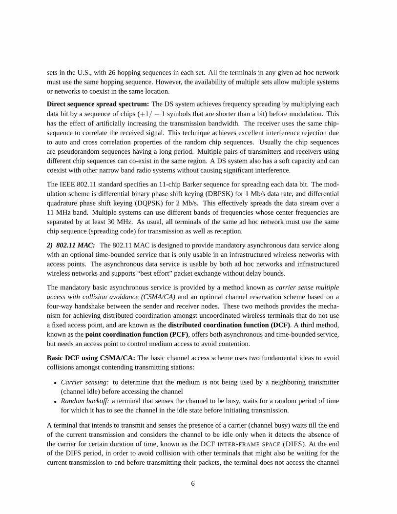
Fig. 3. Illistration of the CSMA/CA protocol.
immediately. Instead, each terminal starts a backoff timer, which is initiated at a random value andcounts down as long as the channel is sensed idle. The backoff timer is frozen whenever the channel issensed busy, resuming the countdown again after it goes idle (i.e. senses absence of the carrier for atleast DIFS period). The terminal initiates transmission only when its backoff timer reaches zero. Thebackoff interval is slotted, and may be expressed asCWrand×SLOT TIME, whereCWrand is a randominteger chosen uniformly between 0 andCW andSLOT TIME is a predetermined slot duration.CW isthe contention window, which can take one of the following set of integer values: 7, 15, 31, 63, 127,255. Initially a node uses the smallest value ofCW and uses the next higher value in the set after eachunsuccessful transmission.
In order to indicate that a transmission has been successful, a receiver transmits an ACK packet after aSHORT INTER-FRAME SPACE(SIFS) period (which is shorter than DIFS) immediately following thereception of the data packet. In case an ACK is not received, the transmitter assumes that the transmitteddata packet is lost and it schedules a retransmission of the same. This will be continued for a maximumnumber of allowable retries at the MAC before the data packet is discarded.
An illustration of the access control scheme is shown in Figure 3. Here, nodesA, B, andC, all have datapackets to transmit when they find the channel busy (due to a transmission from some nodeX). Afterthe channel is idle for a DIFS period, each node selects a random backoff period. In this illustration, thebackoff timers ofA, B, andC are chosen as 4, 1, and 3, respectively. SoB’s backoff timer reaches zerofirst, when it initiates transmission and the timers of bothA andC are frozen. The transmissions of thedata frames fromA andC take place subsequently, as shown in Figure 3.
7
RTS
CTS
ACK
A
C
B
D
RTS Data
Data
CTS
ACK
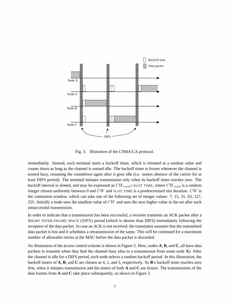
Fig. 4. CSMA/CA with RTS/CTS handshake.
According to this scheme, a collision may happen when multiple stations select the same backoff time.A large valueCW will ensure a small probability of collision as it results in a smaller probability of twonodes selecting the same backoff time. However, a largerCW may cause a node to wait longer beforetransmission. When very few nodes are transmitting, a large value ofCW causes inefficient usage ofthe channel. Hence, initially all nodes set theCW to the smallest value of 7. With heavier traffic, someof the transmissions will collide and eventually higher and higher values ofCW may be chosen by thenodes to ensure collision free transmission.
CSMA/CA with RTS/CTS extension: Though the basic CSMA/CA scheme has excellent mechanismsto avoid collisions amongst a number of uncoordinated nodes that can hear one another, it does notsolve problems due to hidden and exposed terminals. In order to address the hidden terminal problem,802.11 has the option of adding the mechanism of an exchange of REQUEST TO SEND (RTS) andCLEAR TO SEND (CTS) control packets between a transmitting and receiving nodes before initiatingthe transmission of a data packet.
The principle behind the use of the RTS and CTS packets can be seen from Figure 4. Here, nodeA,which intends to send a data packet toB, first broadcasts an RTS packet using the basic CSMA/CAscheme. The RTS frame contains the identity of the destinationB, and the time that would be requiredfor the entire transmission to complete. IfB receives the RTS packet, it replies with a CTS packet afterwaiting for SIFS. The CTS packet also contains the time required for completion of the intended dataexchange and the identity of the transmitting node. Upon receiving the CTS packet fromB, A waits forSIFS and then transmits the data packet. When the data packet is received,B sends an ACK packet afterSIFS, thus completing one entire data packet transfer protocol. All neighbors ofA andB that receiveeither the RTS and/or the CTS learn about the intended exchange process and cooperate by remainingsilent for the period of time that is required for the data exchange to be over.
The exchange of RTS and CTS packets serves two purposes:
• First, if A receives the CTS, it is ascertained thatB is ready to receive and there are no interferingtransmissions near nodeB. This process thus serves as a “virtual carrier sensing” mechanism.
• Second, all neighboring nodes of the destination, including those hidden fromA (such asC), are
8

expected to hear the CTS packet and remain silent for as long as it is required for the data transmis-sion to be over. Neighbors ofA (such asD) also remain silent for the period specified by the RTSso that their own transmissions do not experience any interference from the data packet to be trans-mitted fromA. A silent period is implemented in a listening node by setting itsNET ALLOCATION
VECTOR (NAV) in accordance to the duration field in the RTS or CTS, which specifies the earliestpossible time at which it can access the channel again. Hence, the RTS/CTS exchange effectivelyreservesthe channel for the intended data transmission fromA to B.
Even though the data packets have higher probability of success due to this channel reservation tech-nique enacted by the RTS/CTS exchange, the RTS and CTS packets themselves are susceptible to thesame rate of failure as that of the basic CSMA/CA scheme. Many of these control packets may sufferloss due to collisions and require retransmissions before the channel reservation is performed success-fully. However, since the RTS and CTS control packets are shorter than the data packets, the schemeusually has a better throughput performance than the basic CSMA/CA in the presence of hidden termi-nals. Comprehensive analysis of the performance of the DCF under various conditions in mobile ad hocnetworks have been reported in [7], [58], [5].
B. ADDITIONAL I SSUES ONMAC
Several concerns with the IEEE 802.11 MAC has motivated researchers to explore newer techniques toimprove the channel utilization and throughput in mobile ad hoc networks. The basic access methodof the 802.11 MAC protocol is susceptible to inefficiencies due to the hidden and exposed terminalproblems. The RTS/CTS option reduces the hidden terminal problem but not the inefficiency caused bythe exposed terminal problem. Some other concerns of 802.11 DCF using the RTS/CTS dialog are:
Additional overhead of control packets: The transmission RTS and CTS control packets consume anadditional amount of bandwidth and may lead to significant delays in data transmission if they expe-rience a high amount of collisions and retransmissions. Usually this is justified when the size of thedata packets is large and the advantage gained from saving the loss of data packets far outweighs theadditional overhead incurred by the transmission of RTS and CTS packets. However, it has been ob-served that especially in higher loads and under high mobility, most of the transmission bandwidth maybe consumed for repeated transmissions of the RTS and CTS control packets with very little data trafficbeing possible [21].
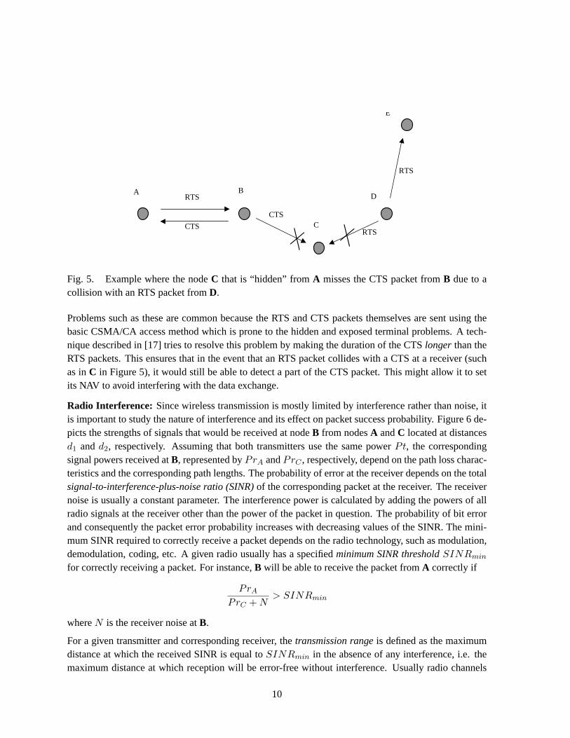
Collisions of control packets:Since the RTS and CTS packets are susceptible to collisions, the channelreservation scheme may fail leading to loss of data packets as well. Figure 5 illustrates such an examplescenario. HereA starts an RTS-CTS dialog withB before transmitting a data packet to it. The CTSreply fromB is received byA correctly, but it is not received byC, which is hidden fromA, due to acollision with an RTS packet sent fromD to E. This happens becauseD, being far away from bothAandB, does not hear either the RTS or the CTS packet and is unaware of the communication betweenA andB. NodeA assumes that the channel is successfully reserved and proceeds with transmission ofthe data packet toB. This data transmission is vulnerable to interference fromC, which has not beenable to set its NAV accordingly, and may initiate a transmission to any of its neighbors before the datatransmission is over.
9
A B
C
E
D RTS
CTS RTS
RTS
CTS
Fig. 5. Example where the nodeC that is “hidden” fromA misses the CTS packet fromB due to acollision with an RTS packet fromD.
Problems such as these are common because the RTS and CTS packets themselves are sent using thebasic CSMA/CA access method which is prone to the hidden and exposed terminal problems. A tech-nique described in [17] tries to resolve this problem by making the duration of the CTSlonger than theRTS packets. This ensures that in the event that an RTS packet collides with a CTS at a receiver (suchas inC in Figure 5), it would still be able to detect a part of the CTS packet. This might allow it to setits NAV to avoid interfering with the data exchange.
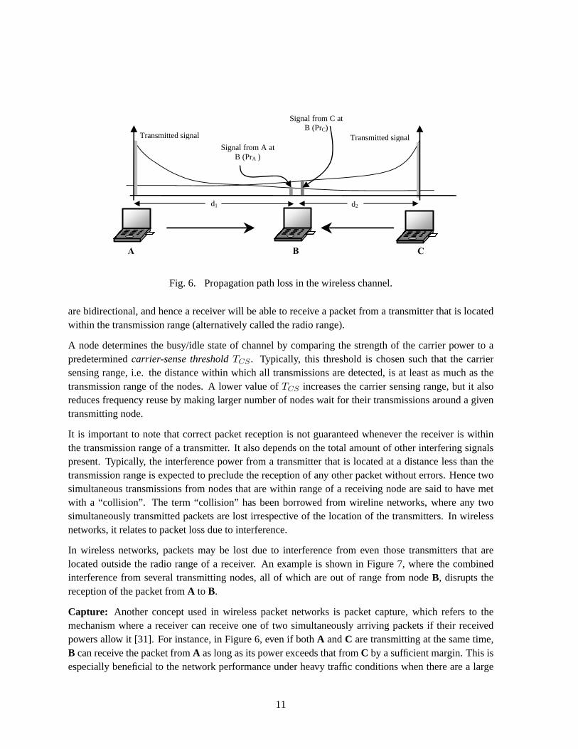
Radio Interference: Since wireless transmission is mostly limited by interference rather than noise, itis important to study the nature of interference and its effect on packet success probability. Figure 6 de-picts the strengths of signals that would be received at nodeB from nodesA andC located at distancesd1 andd2, respectively. Assuming that both transmitters use the same powerPt, the correspondingsignal powers received atB, represented byPrA andPrC , respectively, depend on the path loss charac-teristics and the corresponding path lengths. The probability of error at the receiver depends on the totalsignal-to-interference-plus-noise ratio (SINR)of the corresponding packet at the receiver. The receivernoise is usually a constant parameter. The interference power is calculated by adding the powers of allradio signals at the receiver other than the power of the packet in question. The probability of bit errorand consequently the packet error probability increases with decreasing values of the SINR. The mini-mum SINR required to correctly receive a packet depends on the radio technology, such as modulation,demodulation, coding, etc. A given radio usually has a specifiedminimum SINR thresholdSINRmin
for correctly receiving a packet. For instance,B will be able to receive the packet fromA correctly if
PrA
PrC + N> SINRmin
whereN is the receiver noise atB.
For a given transmitter and corresponding receiver, thetransmission rangeis defined as the maximumdistance at which the received SINR is equal toSINRmin in the absence of any interference, i.e. themaximum distance at which reception will be error-free without interference. Usually radio channels
10
A B C
Signal from A at B (PrA )
Signal from C at B (PrC)
Transmitted signal Transmitted signal
d1 d2
Fig. 6. Propagation path loss in the wireless channel.
are bidirectional, and hence a receiver will be able to receive a packet from a transmitter that is locatedwithin the transmission range (alternatively called the radio range).
A node determines the busy/idle state of channel by comparing the strength of the carrier power to apredeterminedcarrier-sense thresholdTCS . Typically, this threshold is chosen such that the carriersensing range, i.e. the distance within which all transmissions are detected, is at least as much as thetransmission range of the nodes. A lower value ofTCS increases the carrier sensing range, but it alsoreduces frequency reuse by making larger number of nodes wait for their transmissions around a giventransmitting node.
It is important to note that correct packet reception is not guaranteed whenever the receiver is withinthe transmission range of a transmitter. It also depends on the total amount of other interfering signalspresent. Typically, the interference power from a transmitter that is located at a distance less than thetransmission range is expected to preclude the reception of any other packet without errors. Hence twosimultaneous transmissions from nodes that are within range of a receiving node are said to have metwith a “collision”. The term “collision” has been borrowed from wireline networks, where any twosimultaneously transmitted packets are lost irrespective of the location of the transmitters. In wirelessnetworks, it relates to packet loss due to interference.
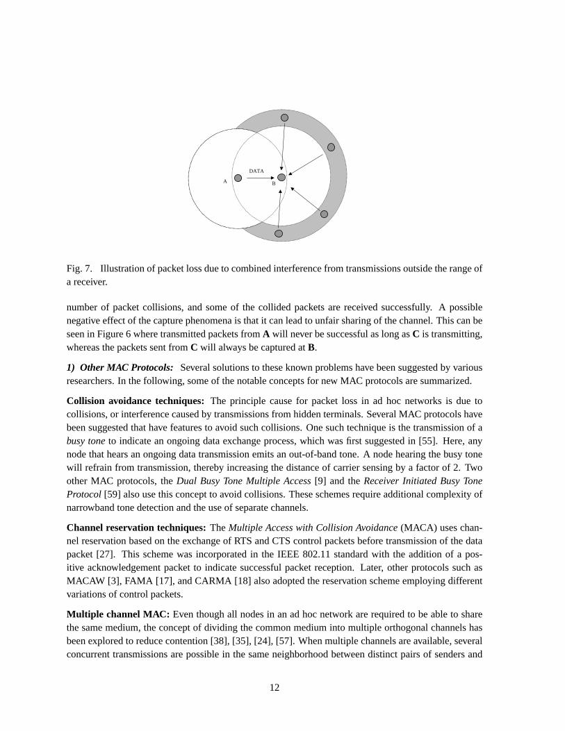
In wireless networks, packets may be lost due to interference from even those transmitters that arelocated outside the radio range of a receiver. An example is shown in Figure 7, where the combinedinterference from several transmitting nodes, all of which are out of range from nodeB, disrupts thereception of the packet fromA to B.
Capture: Another concept used in wireless packet networks is packet capture, which refers to themechanism where a receiver can receive one of two simultaneously arriving packets if their receivedpowers allow it [31]. For instance, in Figure 6, even if bothA andC are transmitting at the same time,B can receive the packet fromA as long as its power exceeds that fromC by a sufficient margin. This isespecially beneficial to the network performance under heavy traffic conditions when there are a large
11
A B
DATA
Fig. 7. Illustration of packet loss due to combined interference from transmissions outside the range ofa receiver.
number of packet collisions, and some of the collided packets are received successfully. A possiblenegative effect of the capture phenomena is that it can lead to unfair sharing of the channel. This can beseen in Figure 6 where transmitted packets fromA will never be successful as long asC is transmitting,whereas the packets sent fromC will always be captured atB.
1) Other MAC Protocols: Several solutions to these known problems have been suggested by variousresearchers. In the following, some of the notable concepts for new MAC protocols are summarized.
Collision avoidance techniques:The principle cause for packet loss in ad hoc networks is due tocollisions, or interference caused by transmissions from hidden terminals. Several MAC protocols havebeen suggested that have features to avoid such collisions. One such technique is the transmission of abusy toneto indicate an ongoing data exchange process, which was first suggested in [55]. Here, anynode that hears an ongoing data transmission emits an out-of-band tone. A node hearing the busy tonewill refrain from transmission, thereby increasing the distance of carrier sensing by a factor of 2. Twoother MAC protocols, theDual Busy Tone Multiple Access[9] and theReceiver Initiated Busy ToneProtocol [59] also use this concept to avoid collisions. These schemes require additional complexity ofnarrowband tone detection and the use of separate channels.
Channel reservation techniques:TheMultiple Access with Collision Avoidance(MACA) uses chan-nel reservation based on the exchange of RTS and CTS control packets before transmission of the datapacket [27]. This scheme was incorporated in the IEEE 802.11 standard with the addition of a pos-itive acknowledgement packet to indicate successful packet reception. Later, other protocols such asMACAW [3], FAMA [17], and CARMA [18] also adopted the reservation scheme employing differentvariations of control packets.
Multiple channel MAC: Even though all nodes in an ad hoc network are required to be able to sharethe same medium, the concept of dividing the common medium into multiple orthogonal channels hasbeen explored to reduce contention [38], [35], [24], [57]. When multiple channels are available, severalconcurrent transmissions are possible in the same neighborhood between distinct pairs of senders and
12
Protocol using a single channel
Time
Ban
dwid
th
F
E
D
C
B
A
PAB PCD
PEF
PAB PCD PEF
Time
Channel 1 Channel 2 Channel 3
Protocol using 3 channels
Ban
dwid
th PAB
PCD
PEF
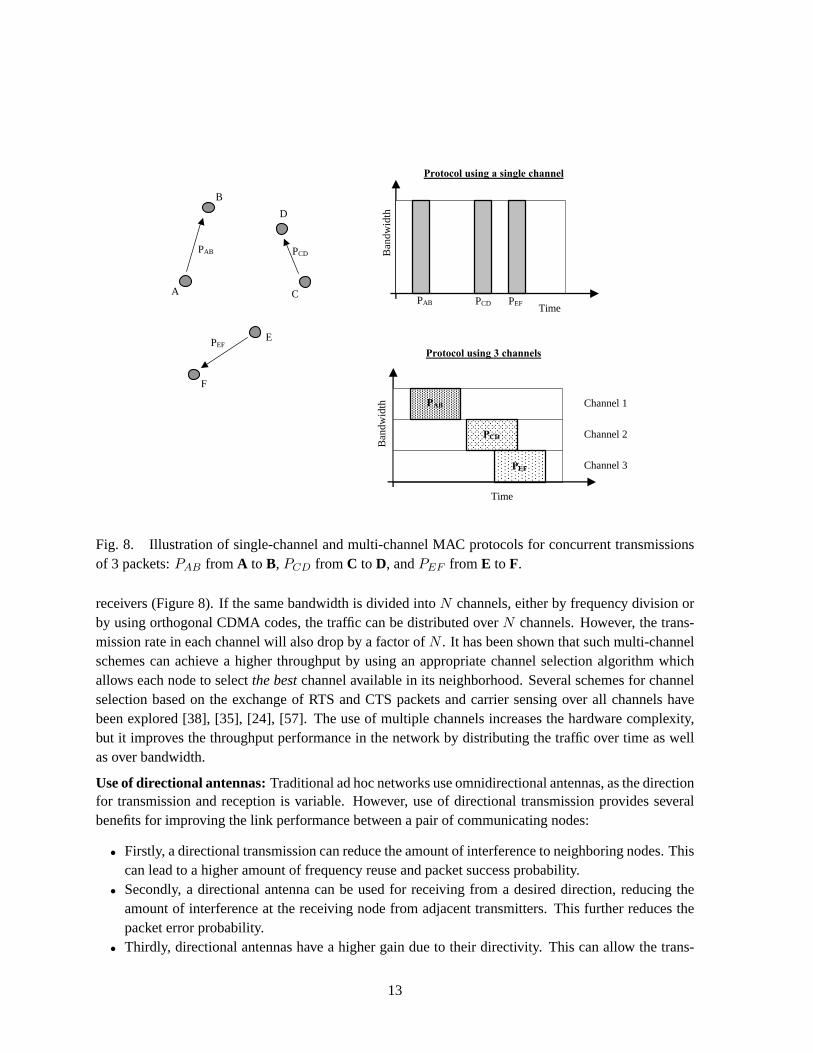
Fig. 8. Illustration of single-channel and multi-channel MAC protocols for concurrent transmissionsof 3 packets:PAB from A to B, PCD from C to D, andPEF from E to F.
receivers (Figure 8). If the same bandwidth is divided intoN channels, either by frequency division orby using orthogonal CDMA codes, the traffic can be distributed overN channels. However, the trans-mission rate in each channel will also drop by a factor ofN . It has been shown that such multi-channelschemes can achieve a higher throughput by using an appropriate channel selection algorithm whichallows each node to selectthe bestchannel available in its neighborhood. Several schemes for channelselection based on the exchange of RTS and CTS packets and carrier sensing over all channels havebeen explored [38], [35], [24], [57]. The use of multiple channels increases the hardware complexity,but it improves the throughput performance in the network by distributing the traffic over time as wellas over bandwidth.
Use of directional antennas:Traditional ad hoc networks use omnidirectional antennas, as the directionfor transmission and reception is variable. However, use of directional transmission provides severalbenefits for improving the link performance between a pair of communicating nodes:
• Firstly, a directional transmission can reduce the amount of interference to neighboring nodes. Thiscan lead to a higher amount of frequency reuse and packet success probability.
• Secondly, a directional antenna can be used for receiving from a desired direction, reducing theamount of interference at the receiving node from adjacent transmitters. This further reduces thepacket error probability.
• Thirdly, directional antennas have a higher gain due to their directivity. This can allow the trans-
13
E
B
A
D
C A
E
D C
B
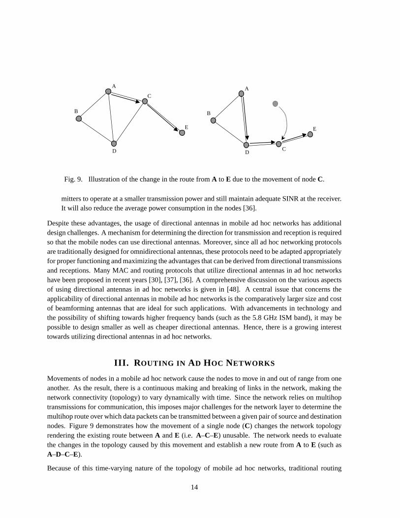
Fig. 9. Illustration of the change in the route fromA to E due to the movement of nodeC.
mitters to operate at a smaller transmission power and still maintain adequate SINR at the receiver.It will also reduce the average power consumption in the nodes [36].
Despite these advantages, the usage of directional antennas in mobile ad hoc networks has additionaldesign challenges. A mechanism for determining the direction for transmission and reception is requiredso that the mobile nodes can use directional antennas. Moreover, since all ad hoc networking protocolsare traditionally designed for omnidirectional antennas, these protocols need to be adapted appropriatelyfor proper functioning and maximizing the advantages that can be derived from directional transmissionsand receptions. Many MAC and routing protocols that utilize directional antennas in ad hoc networkshave been proposed in recent years [30], [37], [36]. A comprehensive discussion on the various aspectsof using directional antennas in ad hoc networks is given in [48]. A central issue that concerns theapplicability of directional antennas in mobile ad hoc networks is the comparatively larger size and costof beamforming antennas that are ideal for such applications. With advancements in technology andthe possibility of shifting towards higher frequency bands (such as the 5.8 GHz ISM band), it may bepossible to design smaller as well as cheaper directional antennas. Hence, there is a growing interesttowards utilizing directional antennas in ad hoc networks.
III. R OUTING IN AD HOC NETWORKS
Movements of nodes in a mobile ad hoc network cause the nodes to move in and out of range from oneanother. As the result, there is a continuous making and breaking of links in the network, making thenetwork connectivity (topology) to vary dynamically with time. Since the network relies on multihoptransmissions for communication, this imposes major challenges for the network layer to determine themultihop route over which data packets can be transmitted between a given pair of source and destinationnodes. Figure 9 demonstrates how the movement of a single node (C) changes the network topologyrendering the existing route betweenA andE (i.e. A–C–E) unusable. The network needs to evaluatethe changes in the topology caused by this movement and establish a new route fromA to E (such asA–D–C–E).
Because of this time-varying nature of the topology of mobile ad hoc networks, traditional routing
14
techniques, such as the shortest-path and link-state protocols that are used in fixed networks, cannot bedirectly applied to ad hoc networks. A fundamental quality of routing protocols for ad hoc networksis that they mustdynamicallyadapt to variations of the network topology. This is implemented bydevising techniques for efficiently tracking changes in the network topology and rediscovering newroutes when older ones are broken. Since an ad hoc network is infrastructureless, these operations are tobe performed in adistributedfashion with the collective cooperation of all nodes in the network. Someof the desirable qualities of dynamic routing protocols for ad hoc networks are:
• Routing overhead:Tracking changes of the network topology requires exchange of control pack-ets amongst the mobile nodes. These control packets must carry various types of information,such as node identities, neighbor lists, distance metrics, etc., which consume additional bandwidthfor transmission. Since wireless channel bandwidth is at a premium, it is desirable that the rout-ing protocol minimizes the number and size of control packets for tracking the variations of thenetwork.
• Timeliness:Since link breakages occur at random times, it is hard to predict when an existing routewill expire. The timeliness of adaptation of the routing protocol is crucial. A broken route causesinterruption in an ongoing communication until a new route is established. Often the newly redis-covered route may be largely disjoint from the older route, which creates problems in rerouting thepackets that were already transferred along the route and could not be delivered to the destination.Ideally, a new route should be determined before the existing one is broken, which may not bepossible. Alternatively, a new route should be established with minimum delay.
• Path optimality: With constraints on the routing overhead, routing protocols for mobile ad hocnetworks are more concerned with avoiding interruptions of communication between source anddestination nodes rather than the optimality of the routes. Hence, in order to avoid excess trans-mission of control packets, the network may be allowed to operate with suboptimal (which are notnecessarily the shortest) routes until they break. However, a good routing protocol should minimizeoverhead as well as the path lengths. Otherwise, it will lead to excessive transmission delays andwastage of power.
• Loop freedom: Since the routes are maintained in a distributed fashion, the possibility of loopswithin a route is a serious concern. The routing protocol must incorporate special features so thatthe routes remain free of loops.
• Storage complexity:Another problem of distributed routing architectures is the amount of storagespace utilized for routing. Ad hoc networks may be applied to small portable devices, such assensors, which have severe constraints in memory and hardware. Hence, it is desirable that therouting protocol be designed to require low storage complexity.
• Scalability: Routing protocols should be able to function efficiently even if the size of the networkbecomes large. This is not very easy to achieve, as determining an unknown route between a pairof mobile nodes becomes more costly in terms of the required time, number of operations, andexpended bandwidth when the number of nodes increases.
Because of its many challenges, routing has been a primary focus of researchers in mobile ad hocnetworks. The MANET working group in the IETF has been working on the issue of standardizingan IP based routing standard for mobile ad hoc networks. Consequently, a large number of dynamic
15
Ad hoc routing protocols
Proactive (table-driven)
Reactive (on-demand)
Hybrid
DSDV OLSR FSR FSLS DSR AODV ZRP LANMAR
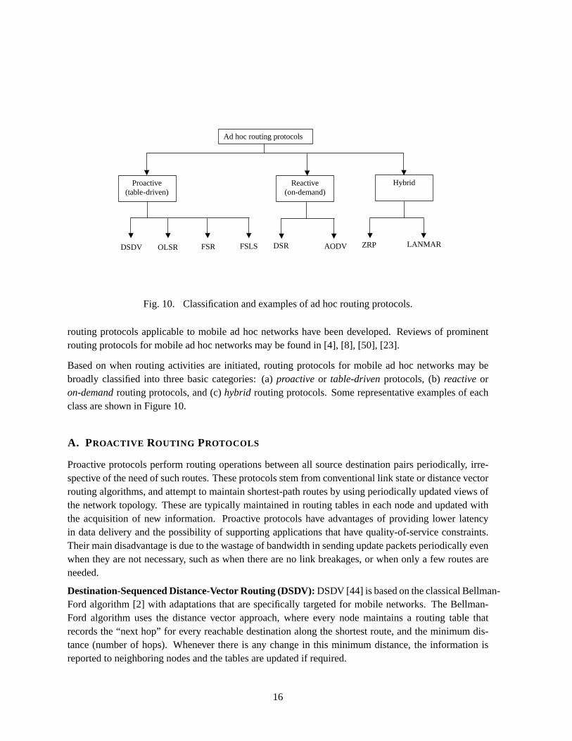
Fig. 10. Classification and examples of ad hoc routing protocols.
routing protocols applicable to mobile ad hoc networks have been developed. Reviews of prominentrouting protocols for mobile ad hoc networks may be found in [4], [8], [50], [23].
Based on when routing activities are initiated, routing protocols for mobile ad hoc networks may bebroadly classified into three basic categories: (a)proactiveor table-drivenprotocols, (b)reactiveoron-demandrouting protocols, and (c)hybrid routing protocols. Some representative examples of eachclass are shown in Figure 10.
A. PROACTIVE ROUTING PROTOCOLS
Proactive protocols perform routing operations between all source destination pairs periodically, irre-spective of the need of such routes. These protocols stem from conventional link state or distance vectorrouting algorithms, and attempt to maintain shortest-path routes by using periodically updated views ofthe network topology. These are typically maintained in routing tables in each node and updated withthe acquisition of new information. Proactive protocols have advantages of providing lower latencyin data delivery and the possibility of supporting applications that have quality-of-service constraints.Their main disadvantage is due to the wastage of bandwidth in sending update packets periodically evenwhen they are not necessary, such as when there are no link breakages, or when only a few routes areneeded.
Destination-Sequenced Distance-Vector Routing (DSDV):DSDV [44] is based on the classical Bellman-Ford algorithm [2] with adaptations that are specifically targeted for mobile networks. The Bellman-Ford algorithm uses the distance vector approach, where every node maintains a routing table thatrecords the “next hop” for every reachable destination along the shortest route, and the minimum dis-tance (number of hops). Whenever there is any change in this minimum distance, the information isreported to neighboring nodes and the tables are updated if required.
16
To make this algorithm adequate for mobile ad hoc networks, DSDV added asequence numberwith eachdistance entry to indicate thefreshnessof that entry. A sequence number is originated at the destinationnode, and is incremented by each node that sends an update to its neighbors. Thus, a newer routingtable update for the same destination will have a higher sequence number. Routing table updates areperiodically transmitted throughout the network, with each node updating its routing table entries basedon the latest sequence number corresponding to that entry. If two updates for the same destination haveidentical sequence numbers but different distances, then the shorter distance is recorded. The addition ofsequence numbers remove the possibility of long lived loops and also thecounting-to-infinityproblem,where it takes a large number of update messages to ascertain that a node is not reachable [44]
Optimized Link State Routing Protocol (OLSR): OLSR is a comparatively newer proactive routingprotocol [15]. It is an adaptation of conventional link-state routing in which each node tries to maintaininformation about the network topology. Each node determines the link costs to each of its neigh-bors by broadcastingHELLO messages periodically. Whenever there is a change in the link costs, thenode broadcasts this information to all other nodes. In classical link-state algorithms, this is done byeach nodeflooding the whole network with update packets containing updated link costs. Nodes usethis information to apply a shortest path algorithm (such as Dijkstra’s shortest path algorithm [11]) todetermine the best route to a specific destination.
OLSR optimizes the link-state protocol in two ways. First, it reduces the size of the update packetssent during the broadcasts by including only a subset of links to its neighbors. These are the links toa select set of neighbors known as themultipoint relays (MPR). The set of MPRs of a node consistof the minimum set of one hop neighbors of that node so that the node can reach all of its two hopneighbors by using these nodes as relay points. Each node computes its MPR set from the exchangeof neighborhood information with all its neighbors. Second, instead of every neighbor broadcasting theupdate packets sent out by a node, only the MPR nodes participate in broadcasting of these packets inOLSR. This minimizes the traffic of control packets during flooding. However, the savings of bandwidthachieved using these two techniques come at a cost of propagating incomplete topology information inthe network. The updates include only MPR sets and not the sets of all neighbors of the broadcastingnodes. Hence, a shortest path algorithm based on this partial topology information will generate routescontaining the MPR nodes only. When the network is dense, i.e. when each node has many neighbors,OLSR will work out to be efficient due to the reduction of control traffic for updates in the network.
Issues in proactive routing: The key characteristic of proactive routing protocols is that updates aresent periodically irrespective of need. Another issue is that they are table-driven. These two propertiescause serious problems for making proactive routing protocols scale with network size. However, theseprotocols work well under heavy traffic and high mobility conditions as they try to maintain fresh routinginformation continuously.
Several new approaches have been proposed to make proactive protocols more scalable. One example isFisheye State Routing (FSR)[41], which is also an adaptation of link-state routing to ad hoc networks.FSR tries to limit routing load by avoiding flooding the network with routing information. Entire linkstate information is only transmitted to the first hop neighbors. In addition, it uses lower update ratesfor nodes that are located further away. Hence, FSR maintains accurate route information on nodes
17
that are close by but the accuracy degrades with increasing distance of the destination from the source.Overall, this technique saves the volume and size of routing traffic. A similar approach is adopted in theFuzzy Sighted Link State algorithm (FSLS)[51]. As discussed above, OLSR reduces routing load bybroadcasting incomplete topology information. In general, these sacrifices lead to increased scalabilityof proactive routing protocols.
B. REACTIVE ROUTING PROTOCOLS
Reactive protocols are designed to minimize routing overhead. Instead of tracking the changes in thenetwork topology to continuously maintain shortest path routes to all destinations, these protocols de-termine routes only when necessary. Typically, these protocols perform aroute discoveryoperationbetween the source and the desired destination when the source needs to send a data packet and theroute to the destination is not known. As long as a route is live, reactive routing protocols only performroute maintenanceoperations and resorts to a new route discovery only when the existing one breaks.The advantage of thison-demandnature of operation is that it usually has a much lower average routingoverhead in comparison to proactive protocols. However, it has the disadvantage that a route discoverymay involvefloodingthe entire network with query packets. Flooding is wasteful, which can be requiredquite frequently in case of high mobility or when there are a large number of active source-destinationpairs. Moreover, route discovery adds to the latency in packet delivery as the source has to wait tillthe route is determined before it can transmit. Despite these drawbacks, on-demand protocols receivecomparatively more attention than proactive routing protocols, as the bandwidth advantage makes themmore scalable.
Dynamic Source Routing (DSR):DSR is a reactive routing protocol that uses a concept calledsourcerouting [25]. Each node maintains aroute cachewhere it lists the complete routes to all destinationsfor which the routes are known. A source node includes the route to be followed by a data packet in itsheader. Routes are discovered on demand by a process known asroute discovery. When a node doesnot have a route cache entry for the destination to which it needs to send a data packet, it initiates aroute discovery by broadcasting a routeREQUESTor QUERY message seeking a route to the destination.The REQUESTpacket contains the identities of the source and the desired destination. Any node thatreceives aREQUESTpacket first checks its route cache for an existing entry to the desired destination.If it does not have such an entry, the node adds its identity to the header of theREQUESTpacket andtransmits it. Eventually, theREQUESTpacket will flood the entire network by traversing to all the nodestracing all possible paths. When aREQUESTpacket reaches the destination, or a node that has a knownroute to the destination, aREPLY is sent back to the source following the same route that was traversedby thatREQUESTpacket in the reverse direction. This is done by simply copying the sequence of nodeidentities obtained from the header ofREQUESTpacket. TheREPLY packet contains the entire route tothe destination, which is recorded in the source node’s route cache.
When an existing route breaks, it is detected by the failure of forwarding data packets on the route. Sucha failure is observed by the absence of the link layer acknowledgement expected by the node where thelink failure has occurred. On detecting the link failure, the node sends this information back anERROR
packet to the source. All nodes that receive theERRORpacket, including the source, delete all existing
18
routes from their route caches that contain the specified link. If a route is still needed, a fresh routediscovery is initiated.
Ad Hoc On Demand Distance Vector Routing (AODV): AODV [42] can be described as an on-demand extension of the DSDV routing protocol. Like DSDV, each route maintains routing tablescontaining the next hop and sequence numbers corresponding to each destination. However, the routesare created on demand, i.e. only when a route is needed for which there is no “fresh” record in the routingtable. In order to facilitate determination of the freshness of routing information, AODV maintainsthe time since when an entry has been last utilized. A routing table entry is “expired” after a certainpredetermined threshold of time.
The mechanism for creating routes in AODV is somewhat different from that used in DSR. Here, whena node needs a route to some destination, it broadcasts a routeREQUESTpacket in which it includes thelast known sequence number for that destination. TheREQUESTpacket is forwarded by all nodes thatdo not have a fresher route (determined by the sequence numbers) to the specified destination. Whileforwarding theREQUESTpacket, each node records the earlier hop taken by theREQUESTpacket in itsrouting table entry for the source (originator of the route discovery). Hence, a propagatingREQUEST
packet createsreverse routesto the source in the routing tables of all forwarding nodes. When theREQUESTpacket reaches the desired destination or a node that knows a fresher route to it, it generates arouteREPLY packet that is sent back along the same path that was taken by the correspondingREQUEST
packet. TheREPLY packet contains the number of hops to the destination as well as the most recentsequence number. Each node that forwards theREPLY packet enters the routing information for thedestination node in its routing table, thus creating theforward routeto the destination.
Routing table entries are deleted when anERRORpacket is received from one of the intermediate nodeson the route forwarding a data packet to the destination. When such anERROR packet reaches thesource, it may initiate a fresh route discovery to determine a fresh route to the destination.
Issues in reactive routing:Since reactive routing protocols only transmit routing packets when needed,these protocols are comparatively more efficient when there are fewer link breakages, such as under lowmobility conditions. In addition, when there are only a few communicating nodes in the network, therouting functions are only concerned with maintaining the routes that are active. Because of thesebenefits, reactive or on-demand routing protocols have received more attention than proactive protocolsfor mobile ad hoc networks.
The main concern with reactive routing protocols is the need for flooding the entire network in search ofa route when needed. Many optimizations have been suggested to reduce the excessive number of rout-ing packets transmitted throughout the network during such flooding operations in reactive protocols.For instance, DSR has the option of broadcasting anonpropagating request packetfor route discovery,which in that case is broken into two phases. In the first phase, the source broadcasts a nonpropagatingroute request packet that only queries its first hop neighbors for a known route to the destination. Thesepackets are not forwarded by the neighbors. If none of the neighbors return a route, the source thenproceed to the second phase where a traditional propagating request packet is sent. The advantage ofthis scheme is that it avoids a network-wide flood of request packets when the route to the destination isknown by one of the first-hop neighbors. A similar scheme is implemented in AODV using the concept
19
of an expanding ring search. Here, increasingly larger neighborhoods, controlled by either hop-wiseor time-wise constrained request packets, are searched to find the route to the destination. Some othertechniques that perform similar optimizations are:salvaging, where an intermediate node in DSR usesan alternative route from its own cache when the original route is broken; andpromiscuous listening, inwhich a node that overhears a packet not addressed to itself finds that it has a shorter route to the samedestination, and sends agratuitous replyto the source with this new route. This increases the freshnessof the route cache entries without additional route discoveries.
C. HYBRID ROUTING PROTOCOLS
The use ofhybrid routing is an approach that is often used to obtain a better balance between theadaptability to varying network conditions and the routing overhead. These protocols use a combina-tion of reactive and proactive principles, each applied under different conditions, places, or regions.For instance, a hybrid routing protocol may benefit from dividing the network into clusters and apply-ing proactive route updates within each cluster and reactive routing across different clusters. Routingschemes that employ proactive route maintenance on top of reactive route discoveries have also beenconsidered.
Zone Routing Protocol (ZRP): ZRP [22] divides the network intozonesor clusters of nodes. Thenodes within each zone maintain routing information for one another using a proactive algorithm suchas a distance vector or link state protocol. Hence, all nodes maintain updated routing tables consisting ofroutes to all other nodes within the same zone (known asintra-zone routing). Each zone also identifiesa set ofperipheral nodesthat are located at the edges of the zone for communication with other zones.When a packet is to be sent to a node for which the source does not have an entry in its routing table, itis assumed that the destination is located in another zone. In that case, the node requests the peripheralnodes to send out a route request packet to all other zones in the networks. This is known asinter-zonerouting, which uses a process that is similar to DSR except that the request packets are only handledby the peripheral nodes in the network. When the request packet reaches a peripheral node of the zonethat contains the destination, a reply is sent back to the source. The overhead of flooding in such aroute discovery is limited due to the involvement of peripheral nodes only. The proactive protocol inthis hybrid framework limits the spread of periodic update packets within each zone. ZRP is especiallysuitable for large networks, however the flooding of request packets during interzone route discoveriesmay still be a cause of concern.
Landmark Ad Hoc Routing Protocol (LANMAR): LANMAR is designed for ad hoc networks whichhave the characteristics of group mobility, such as a group of soldiers moving together in a battlefield.Each group dynamically identifies a specific node within the group to be alandmarknode. A proactivelink state routing protocol is used to maintain routing information within the group and a distance vectoralgorithm is used to do the same amongst all landmark nodes. Hence, each node has detailed topologyinformation for all nodes within the group and distance and routing vector information to all landmarks.No routing information is maintained for non-landmark nodes belonging to other groups. Packets to besent to such a destination are forwarded towards the corresponding landmark. When the packet reachesthe nodes within the group containing the destination, it is forwarded to the destination, possibly withoutgoing through its landmark. This scheme reduces the size of routing tables as well as the overhead of
20
routing traffic forming a two-level routing hierarchy. Hence, it is expected to be more scalable than theso calledflat routing protocols.
D. OTHER CONCEPTS IN AD HOC ROUTING
There is an increasing list of new ideas and protocols for routing in mobile ad hoc networks. TheMANET working group in the IETF publishes all significant developments and discussions by the grouponline in its mailing list [20], which is the most comprehensive source of up-to-date information onresearch on ad hoc routing protocols. In addition to the representative protocols in the three broadcategories of routing protocols described above, it is worthwhile to look at some of the other conceptsthat have been applied to routing in mobile ad hoc networks.
Geographic position aided routing:The fundamental problems of routing in ad hoc networks arise dueto the random movements of the nodes. Such movements make topological information stale, and hence,when an on demand routing protocol needs to find the route, it often has to flood the entire networklooking for the destination. One of the ways of reducing the wastage of bandwidth in transmittingroute request packets to every node in the network is to confine the search using geographical locationinformation. Geographical Positioning Systems (GPS)can detect the physical location of a terminalusing universal satellite-transmitted wireless signals. In recent times, GPS systems have become smaller,more versatile, as well as cost effective. Hence, several protocols have been proposed which assumesthe presence of a GPS receiver in each node and utilizes the location information in routing [39], [29],[54], [1].
One of the approaches for utilizing geographic location information in routing is toforward data packetsin the directionof the location of the destination node, as proposed in [39], [1], [54]. It may be requiredto define geographic location specific addresses instead of logical node addresses to do that [39].
An alternative concept is proposed in theLocation Aided Routing (LAR)protocol [29], which useslocation information in on-demand routingto limit the spread of request packetsfor route discoveries.LAR uses information such as the last known location and speed of movements of a destination todetermine aREQUEST ZONE, which is defined as a restricted area within which theREQUESTpacketsare forwarded in order to find the destination. Two different ways of definingREQUEST ZONEShavebeen proposed. The idea is to allow route request packets to be forwarded by only those nodes thatlie within the REQUEST ZONE, specified by the source. This limits the overhead of routing packets forroute discovery, which would normally be flooded over the whole network.
A related protocol that usesspatial localitybased on hop counts to confine the spread of request packetswas proposed in [6]. This protocol uses the concept that once an existing route is broken, a new routecan be determined within a certain distance (measured in number of hops) from the old route. Theprotocol confines the spread of route request packets while searching for a new route to replace one thatis freshly broken. For a new route discovery where no earlier routes were in record, the protocol stilluses traditional flooding. However, thisquery localizationtechnique for rediscovering routes still savesrouting overhead.
Stability based routing: A different approach to improve the performance of routing in mobile ad hoc
21
networks is based on using routes that are selected on the basis of theirstability. The AssociativityBased Routing (ABR)protocol [56] maintains anassociation stability metricthat measures the durationof time for which a link has been stable. While discovering a new route, the protocol selects paths thathave a high aggregate association stability. This is done with the idea that a long-lived link is likely tobe stable for a longer interval than a link that has been relatively shortlived.
Signal Stability Based Routing (SSR)[12] uses signal strengths to determine stable links. It allows thediscrimination between “strong” and “weak” links when a route request packet is received by a node.The request packet is forwarded by the node if it has been received over a strong link. This allows theselection of routes that are expected to be stable for a longer time.
Multipath routing: On demand or reactive routing protocols suffer from the disadvantage that datapackets cannot be transmitted until the route discovery is completed. This delay can be significant underheavy traffic conditions when theREQUESTand/or theREPLY packet may take a considerable amountof time in traversing its path. This characteristic, along with the fact that each route discovery processconsumes additional bandwidth for the transmission ofREQUESTandREPLY packets motivate us to findways to reduce the frequency of route discoveries in on-demand protocols. One way of doing that is tomaintain multiple alternate routes between the same source-destination pair such that when the primaryroute breaks, the transmission of data packets can be switched over to the next available path in thememory. Under the assumption that multiple paths do not break at the same time, which is most oftentrue if the paths are sufficiently disjoint, the source may delay a fresh route discovery if the alternatepaths are usable. As a result, many routing protocols have been designed to maintain multiple paths orroutes for each pair of source and destination nodes.
The Temporally Ordered Routing Algorithm (TORA) [40] provides multiple alternate paths by main-taining a “destination oriented” directed acyclic graph from the source. The DSR protocol also has anoption of maintaining multiple routes for each destination in the route cache, so that an alternate routecan be used upon failure of the primary route. Two multipath extensions of DSR were proposed in [34]which aggressively determine multiple disjoint paths for each destination. Here, two different schemesfor selecting alternative routes were considered, both benefiting from reducing the frequency of routediscoveries caused by link breakages. Several other multipath routing protocols that derive benefitsusing the same principle have also been proposed [45], [16], [32].
Preemptive routing: A purely reactive routing protocol typically does not avoid a multihop commu-nication from being interruptedbefore the route breaks due to a link failure. Most reactive routingprotocols initiate a fresh route discovery when anERRORpacket is received at the source due to a linkbreakage. This introduces a pause in the communication until a new route is found. The goal ofpre-emptive routingprotocols is to avoid such pauses by triggering a route discovery and switching to anew (and hopefully better) route before the existing route breaks. Such protocols can be viewed as acombination of proactive and reactive routing, where the route maintenance is performed proactivelybut the basic routing framework is reactive.
The crucial design issue in such protocols is to detect when to initiate a preemptive route discovery tofind a “better” route. The protocol proposed in [19] uses the technique of determining this by observingwhen the signal strength falls below a predetermined threshold. If the wireless channel is relatively
22
static, then this correctly detects the initiation of link failure due to increasing distance between thetwo nodes in the link. However, multipath fading and shadowing effects might lead to false alarmswhile using this technique. Alternatively, using a time-to-live parameter was proposed in [33]. In thisprotocol, a preemptive route discovery is initiated when a route has been in use for a predeterminedthreshold of time. The preemption obviously makes the route discoveries more frequent than whatwould be observed in a purely reactive scheme. To keep the routing overhead low, the preemptiverouting protocol presented in [33] proposes the use of query localization in the preemptive searches.
IV. C ONCLUSION
The mobile ad hoc network is one of the newest members in the family of wireless networks that spanthe planet. This chapter has aimed to provide the main issues and an overview of the developments inthe MAC and routing protocols for mobile ad hoc networks. Although a vast amount of work has beendone on it in the recent past, many questions still remain unanswered. Some of the issues that needfurther thought are presented below:
• MAC: How can we design improved and robust MAC schemes that would dynamically adjust tovariations of the wireless link characteristics and simultaneously cater to the need for higher datarates, quality-of-service requirements, and power savings, that would be crucial in many futureapplications?
• Routing: By far the biggest issue in mobile ad hoc networking research is routing. With the rapidand diverse nature of growth of mobile ad hoc networks, the choice of the routing protocol islikely to depend in the network size, mobility, and application requirements. However, it will beinteresting to see if an approach to generate a unified standard for ad hoc routing is achievable.
• Transport: The issues of transport layer protocols for mobile ad hoc networks require specialattention. A discussion on these issues is outside the scope of this chapter. It is often said thatoptimizing ad hoc network performance requires a multi-layer approach, where design problemsat different layers of the protocol stack are addressed together for a unified solution. How can wearrive at such a design solution?
• Scalability: Many applications are already being conceived where hundreds of thousands of nodesare being considered for ad hoc networking. How do we design protocols for these large scalenetworks?
• Internet connectivity: What is the best paradigm for extending the reach of the Internet to mobileterminals that form a mobile ad hoc network with access points to th Internet?
• Security: All wireless networks are susceptible to security problems such as eavesdropping andjamming. How can we provide security to mobile ad hoc networks?
• Power: One of the major limitations of portability arises from limitations of battery power. Inaddition to developing improved battery technology, future ad hoc networking protocols have to bemade more power efficient so that the network can survive longer without replacement of batteries.
The above items are far from being a complete list of challenging research problems that ad hoc net-working has posed before us. It is the hope of the author that this chapter has inspired the reader to lookinto some of them in more detail.
23
REFERENCES
[1] S. Basagni, I. Chlamtac, V. R. Syrotiuk, and B. A. Woodward. A distance routing effect algorithm for mobility (DREAM).
In Proceedings of the ACM MOBICOM’1998, October 1998.
[2] D. Bertsekas and R. Gallager.Data Networks. Prentice-Hall, 1987.
[3] Vaduvur Bharghavan, Alan Demers, Scott Shenker, and Lixia Zhang. MACAW: A media access protocol for wireless
LAN’s. In Proceedings of the SIGCOMM’94, pages 212–225, August 1994.
[4] J. Broch, D. A. Maltz, D. B. Johnson, Y-C. Hu, and J. Jetcheva. A performance comparison of multi-hop wireless ad hoc
network routing protocols. InProceedings of the 4th International Conference on Mobile Computing and Networking
(ACM MOBICOM’98), October 1998.[5] F. Cali, M. Conti, and E. Gregori. IEEE 802.11 wireless LAN: Capacity analysis and protocol enhancement. InProceed-
ings of IEEE INFOCOM’98, pages 142–149, 1998.
[6] R. Castaneda and S.R. Das. Query localization techniques for on-demand routing protocols in ad hoc networks.in
Proceedings of the 1999 ACM Mobicom Conference, Aug 1999.
[7] H. S. Chhaya and S. Gupta. Performance modeling of asynchronous data transfer methods of IEEE 802.11 MAC protocol.
In Proc. of IEEE Personal Communications Conference, pages 8–15, October 1996.
[8] S.R. Das, R. Castaneda, J. Yan, and R. Sengupta. Comparative performance evaluation of routing protocols for mobile,
ad hoc networks. In7th Int. Conf. on Computer Communications and Networks (IC3N), October 1998.
[9] Jing Deng and Zygmunt J. Haas. Dual busy tone multiple access (DBTMA): A new medium access control for packet
radio networks. InProceedings of IEEE ICUPS’98, October 1998.
[10] IEEE Standards Department. Wireless LAN medium access control (MAC) and physical layer (PHY) specifications,
IEEE standard 802.11–1997, 1997.[11] E. W. Dijkstra. A note on two problems in connection with graphs.Numerical Mathematics, 1:269–271, Oct. 1959.
[12] R. Dube, C. D. Rais, K. Wang, and S. K. Tripathi. Signal stability based adaptive routing (SSA) for mobile ad hoc
networks.IEEE Personal Communication, Feb. 1997.[13] J. Haarsten et. al. Bluetooth: Vision, goals, and architecture.ACM SIGMOBILE Mobile Computing and Communications
Review, 2(4):38–45, Oct 1998.[14] K. J. Negus et. al. HomeRF and SWAP: Wireless networking for the connected home.ACM SIGMOBILE Mobile
Computing and Communications Review, 2(4):28–37, Oct 1998.
[15] P. Jacquet et al. Optimized link state routing protocol.draft-ietf-manet-olsr-05.txt , 2000. IETF Internet
Draft.[16] D. Ganesan, R. Govindan, S. Shenker, and D. Estrin. Highly-resilient, energy-efficient multipath routing in wireless
sensor networks. InProceedings of ACM/SIGMOBILE MOBIHOC’2001, October 2001.
[17] R. Garces and J. J. Garcia-Luna-Aceves. Floor acquisition multiple access with collision resolution. InProceedings of
the ACM/IEEE Mobile Computing and Networking Conference, pages 10–12, November 1996.
[18] R. Garces and J. J. Garcia-Luna-Aceves. Collision avoidance and resolution multiple access with transmission queues.
ACM Wireless Networks Journal, 1998.[19] T. Goff, N. B. Abu-Ghazaleh, D. S. Phatak, and R. Kahvecioglu. Preemptive routing in ad hoc networks. InProceedings
of the ACM MOBICOM’2001, 2001.
[20] IETF MANET Working Group.http://www.ietf. org/html.charters/manet-charter.html .
[21] Z. J. Haas. On the performance of a medium access control scheme for the reconfigurable wireless networks. In
Proceedings of IEEE MILCOM’97, November 1997.
[22] Z. J. Haas and M. R. Pearlman. The performance of query control schemes for the zone routing protocol.ACM/IEEE
Trans. Net., 9:427–38, Aug. 2001.
[23] X. Hong, K. Xu, and M. Gerla. Scalable routing for mobile ad hoc networks.IEEE Network, 2002.
[24] N. Jain, S. R. Das, and A. Nasipuri. A multichannel mac protocol with receiver-based channel selection for multihop
wireless networks. InProceedings of the IEEE IC3N’2001, October 2001.
[25] D. Johnson and D. Maltz. Dynamic source routing in ad hoc wireless networks. In T. Imielinski and H. Korth, editors,
Mobile computing. Kluwer Academic, 1996.
24
[26] John Jubin and Janet D. Tornow. The DARPA packet radio network protocols.Proceedings of the IEEE, 75(1):21–32,
January 1987.
[27] P. Karn. MACA: A new channel access method for packet radio. InProceedings of ARRL/CRRL Amateur Radio9th
Computer Networking Conference, 1990.
[28] L. Kleinrock and F. A. Tobagi. Packet switching in radio channels: Part–i - carrier sense multiple access modes and their
throughput-delay characteristics.IEEE Transactions in Communications, COM-23(12):1400–1416, 1975.
[29] Y. Ko and N. H. Vaidya. Location-aided routing (LAR) in mobile ad hoc networks. InACM/IEEE International Confer-
ence on Mobile Computing and Networking (MOBICOM), pages 66–75, November 1998.
[30] Y. B. Ko, V. Shankarkumar, and N. H. Vaidya. Medium access control protocols using directional antennas in ad hoc
networks. InProceedings of IEEE INFOCOM’2000, Mar. 2000.
[31] C. T. Lau and C. Leung. Capture models for mobile packet radio networks.IEEE Transactions on Communications,
40(5):917–925, 1992.[32] S-J Lee and M. Gerla. Split multipath routing with maximally disjoint paths in ad hoc networks. InProceedings of IEEE
ICC’2001, 2001.[33] A. Nasipuri, R. Burleson, B. Hughes, and J. Roberts. Performance of a hybrid routing protocol for mobile ad hoc
networks. Proc. of IEEE International Conference of Computer Communication and Networks (ICCCN 2001), Oct.
2001.[34] A. Nasipuri, R. Castaneda, and S. R. Das. Performance of multipath routing for on-demand protocols in mobile ad hoc
networks.ACM/Baltzer Mobile Networks and Applications (MONET) Journal, 6:339–349, 2001.
[35] A. Nasipuri and S. R. Das. Multichannel CSMA with signal power-based channel selection for multihop wireless net-
works. Proc. of IEEE Fall Vehicular Technology Conference (VTC 2000), Sept. 2000.
[36] A. Nasipuri, K. Li, and U. R. Sappidi. Power consumption and throughput in mobile ad hoc networks using directional
antennas. InProceedings of the IEEE International Conference on Computer Communications and Networks (IC3N),
Miami, October 2002.[37] A. Nasipuri, S. Ye, J. You, and R. E. Hiromoto. A MAC protocol for mobile ad hoc networks using directional antennas.
Proc. of IEEE Wireless Communications and Networking Conference (WCNC 2000), Sept 2000.
[38] A. Nasipuri, J. Zhuang, and S. R. Das. A multichannel CSMA MAC protocol for multihop wireless networks.Proc. of
IEEE Wireless Communications and Networking Conference (WCNC’99), Sept 1999.
[39] J. C. Navas and T. Imielinski. Geographic addressing and routing. InProceedings of the ACM MOBICOM’97, 1997.
[40] V. Park and S. Corson. Temporally ordered routing algorithm (TORA) version 1, functional specifi-
cation. http://www.ietf.org/ internet-drafts/ draft-ietf-manet -tora-spec-01. txt ,1998. IETF Internet Draft.
[41] G. Pei, M. Gerla, and T-W Chen. Fisheye state routing: A routing scheme for ad hoc wireless networks. InProc. of the
IEEE ICC, June 2000.[42] Charles Perkins and Elizabeth Royer. Ad hoc on demand distance vector (AODV) routing.
http://www.ietf.org/internet-drafts/draft-ietf-manet-aodv-02.txt , November 1998.IETF Internet Draft.
[43] Charles E. Perkins.Ad Hoc Networking. Addison Wesley, 2002.
[44] Charles E. Perkins and Pravin Bhagwat. Highly dynamic destination-sequenced distance-vector routing (DSDV) for
mobile computers. InProceedings of the ACM SIGCOMM ’94 Conference, pages 234–244, August 1994.
[45] D. S. Phatak and T. Goff. A novel mechanism for data streaming across multiple IP links for improving throughput and
reliability in mobile environments. InProceedings of the IEEE INFOCOM’2002, 2002.
[46] David C. Plummer. An ethernet address resolution protocol: Or converting network protocol addresses to 48 bit ethernet
addresses for transmission on ethernet hardware, November 1982.[47] G. J. Pottie and W. J. Kaiser. Wireless integrated network sensors.Communications of the ACM, 43(5):51–58, May
2000.[48] R. Ramanathan. On the performance of beamforming antennas in ad hoc networks. InProceedings of ACM/SIGMOBILE
MOBIHOC’2001, October 2001.[49] J. Redi and B. Welsh. Energy conservation for tactical robot networks. InProc. IEEE MILCOM, pages 1429–33, 1999.
25
[50] E. M. Royer and C. K. Toh. A reivew of current routing protocols for ad hoc mobile wireless networks.IEEE Pers.
Comm., pages 46–55, April 1999.
[51] C. Santivanez, R. Ramanathan, and I. Stavrakakis. Making link-state routing scale for ad hoc networks. InProc. of 2001
ACM Intl. Symp. Mobile Ad Hoc Net. Comp., Oct. 2001.
[52] N. Schacham and J. Westcott. Future directions in packet radio architectures and protocols.Proceedings of the IEEE,
75(1):83–99, Jan 1987.[53] ETSI Secretariat. Hiperlan functional specification. Draft prETS 300 652, 1995.
[54] I. Stojmenovic and X. Lin. GEDIR: Loop-free location based routing in wireless networks. InProceedings of the Intl.
Conf. on Parallel and Dist. Comp. Sys., Nov. 1999.
[55] F. A. Tobagi and L. Kleinrock. Packet switching in radio channels: Part–II - the hidden terminal problem in carrier sense
multiple-access and the busy-tone solution.IEEE Transactions in Communications, COM-23(12):1417–1433, 1975.
[56] C.-K. Toh. Associativity-based routing for ad hoc mobile networks.Wireless Personal Communications, 4:103–139,
1997.[57] Y-C Tseng, S-L Wu, C-Y Lin, and J-P Shen. A multichannel mac protocol with power control for multihop mobile ad
hoc networks. InProceedings of the 21st Internl. Conf. Dist. Comp. Syst., April 2001.
[58] J. Weinmuller, M. Schlager, A. Festag, and A. Wolisz. Performance study of access control in wireless LANs - IEEE
802.11 DFWMAC and ETSI RES 10 hiperlan.Mobile Networks and Applications, 2:55–67, 1997.
[59] C. Wu and V. O. K. Li. On the performance of a medium access control scheme for the reconfigurable wireless networks.
In Proc. 6th WINLAB Workshop, 1997.
26