mmtty pdf help file
TRANSCRIPT

Introduction
Acknowledgements
Using Help
- Navigate the Help File
- Table of Contents and Index
- Talking About MMTTY
- More Help and Discussion
Printed Copy of Help
This Help file is for MMTTY--Baudot RTTY decoding and encoding software that allows a computer with a
sound card to work with an amateur radio transceiver to receive and send Baudot RTTY signals. MMTTY has a
built-in logging program, and DSP filtering. It is extremely flexible, with many parameters open to operator
control. MMTTY is provided free of charge. It is available at the official distribution site for Mr. Makoto Mori's
software, http://mmhamsoft.amateur-radio.ca.
Here are a few of the important features of MMTTY:
• Generates either AFSK or FSK output. • Can operate a PTT switch via serial port. • Can communicate directly with many computer-enabled ham transceivers to control PTT and to
display frequency. • Has an AFC feature that allows MMTTY to automatically tune in a RTTY signal. • Integrates logging and operating with additional contest features.
Acknowledgements
MMTTY is a Baudot RTTY decode and encode program written by Makoto Mori, JE3HHT. This version of
English Help is a revision of the second version of English Help, written in 2000. The first version of Help
written in English was a summary written by Andrew O'Brien (KB2EOQ at the time, now K3UK). This Help file
is copyrighted by Jan Ditzian, KX2A, beginning November 2003. Contributors to this Help file are:
• Oba, JA7UDE (Most of the troubleshooting solutions come from Oba) • Phil Cooper, GU0SUP
• Don Hill, AA5AU
• Jerry Flanders, W4UK
• John Leroy, W4JKL
• Hams who ask or answer questions on the [email protected] discussion group.
The year 2000 version of the MMTTY Help file, which provided substantial material for this new file, owes its
existence to some of the above persons, along with:
• Andrew O'Brien, K3UK
• Ken Crowston, VE5KC
• Ed Sleight, K4SB
• Bill Musa, K5YG

Using Help
If this is the HTML Help that is included with MMTTY, you can search on a single word, or you can use the
arrow next to the search window to bring up Boolean arguments (AND, OR, NEAR, NOT) to customize your
search. There are hyperlinks to relevant topics, and you can use the back button at the top. Just below the title
of each topic are links to sections within the topic, so you can jump quickly to a section if you know what
information you need. Here are suggestions about how to learn about MMTTY:
• Quick Start topics discuss straightforward hardware set-up of your computer and transceiver, and software set-up of MMTTY. If you download MMTTY and do not make any changes, then MMTTY defaults will be close to a simple set-up.
• The concepts of Mark and Shift are so important to proper operation of RTTY that you should understand them before you transmit a RTTY signal. See the Mark and Shift topic.
• The main MMTTY display is explained in Main Display.
Navigate the Help File
• Click the Show button at the top of this HTML Help display to bring up the Document Map to the left. If there is a list of topics to the left of the text you are now reading, that is the Document Map.
• The Table of Contents, Index, and other Help tools are tabs on the Document Map.
Table of Contents and Index
In the Table of Contents for this Help file, the topics are organized as the Help developers decided they should
be organized. Topics in Contents are nested--some topics are hidden below others. When you click on a topic
with subtopics, the subtopics become visible. This is a good way to find what you want, SOMETIMES, but at
other times you may want to look at all the topics.
The Index for this Help file includes an alphabetic list of all topics, gathered together at the beginning of the
Index. None of the topics are hidden beneath others. If the Table of Contents is not a suitable guide, look at the
Index.
When using the Table of Contents, click on a topic to make it appear to the right. When using the Index, a
double-click makes each topic appear.
The Basic Operation topic contains a number of subtopics that show MMTTY computer screens and how to
use them.
The rest of the topics are oriented toward different tasks that you may do with MMTTY, or explain in depth
about other topics that are not tied to the MMTTY presentation on a computer.

Talking About MMTTY
In this Help file, certain conventions of speech have been adopted to describe how to operate MMTTY
software.
• When you are to make a series of operations to navigate to a certain part of the MMTTY software, the separate operations are separated by a vertical bar. For example, to get to the place where you set transmit parameters, you will see: Click Option | Setup MMTTY | TX tab. This means, click the Option menu choice at the top of the MMTTY display, then click the choice Setup MMTTY on the drop down menu that appears, then click on the TX tab in the display of five tabs that appears.
• MMTTY uses many tabs, subdivided with lines and labels. We call these subdivisions "blocks." • When you are finished making a selection on a tab, you must click OK at the lower right to make it
happen. If you do not want to make changes, you can ignore your previous clicks by clicking Cancel. • You can make several changes and all of them will be accepted when you click OK. • To press a button on MMTTY's display, put the mouse cursor on the button and left-click. The
button will appear to go down, just like a physical button on a transceiver. Click again to bring it back up.
• PTT (push-to-talk) is used to refer to arrangements for switching from transmit to receive. • VOX refers to transmit/receive switching in the transceiver which senses sound on an input line. • Because of limitations in how pictures are displayed, some screen shots are split into a left half and
a right half. This increases the clarity of the pictures.
More Help and Discussion
There is a MMTTY discussion group on the internet. This is a place to ask questions of other users and even to
make recommendations about the future of MMTTY. Makoto Mori would appreciate it if you did not contact him
directly, but used the group. Here is how to join.
1. Go tohttp://www.yahoogroups.com
2. Sign up for the MMTTY group. 3. You can do a search for keywords in previous posts to find out what has been discussed. 4. You can post a question to the group. Before you do this, though, look over this Help file, including
the Troubleshooting topic.
Printed Copy of Help
The Windows HTML file reader allows you to print this Help file one topic at a time. You can print also print the
subtopics of a topic at that time. At the top of the Help display, click Print.
Internet Links
There are some links to internet resources in this Help file. The url, current as of February 2004, is printed, and
the links are hyperlinks. To use these hyperlinks, the computer on which you see the Help file must have
access to the internet and must have a copy of Microsoft Internet Explorer.

Basic Operation
Basic Operation contains a number of topics that show MMTTY screens and explain how to use them. Here is
a structure of the material below this Basic Operation topic. Each of these are links to the topic in question.
Quick Start
- Quick Start AFSK Set-Up
- Quick Start AFSK Receive
- Quick Start AFSK Transmit
Vista Considerations
Main Display
- Main Menu
- Control Panel
- Control Buttons
- Demodulator Controls
- Demodulator Buttons and Squelch Display
- Macro Buttons
- FFTand XY Displays
- Logging Menu
- Receive Window
- Transmit Menu
- Transmit Window
Set-Up MMTTY
- Demodulator Tab
- AFC/ATC/PLL Tab
- Decode Tab
- TX Tab
- Radio Command
- Font/Window Tab
- Misc Tab
Transmit and Receive Control (PTT)
- Two-Switch PTT
- PTT Using a Pin on a Serial Port
- VOX Control of PTT
- Software Control of PTT
- PTT With a USB Port

Quick Start
The Quick Start series of topics show how to receive and transmit RTTY with a transceiver and MMTTY, using
simple hardware and procedures. There are more advanced hardware and software approaches you should
investigate later. The purpose of Quick Start is to get you started.
Quick Start consists of the following topics:
• Quick Start • Selecting the SoundCard
• Quick Start AFSK Set-up
• Quick Start AFSK Receive
• Quick Start AFSK Transmit
MMTTY requires a soundcard for operation. The soundcard is used for receive in both AFSK and FSK receive
and for AFSK transmit. In computers with more than one soundcard - including those with USB soundcards,
USB headsets or interfaces like those available from microHAM - the soundcard to be used for MMTTY should
be selected from the SoundCard tab in Options | Setup MMTTY.
MMTTY uses an audio signal from the transceiver to decode RTTY. This hookup is covered in Quick Start
AFSK Set-up.
Quick Start AFSK Receive shows how to receive (decode) RTTY. MMTTY comes with defaults so it receives
properly.
Quick Start AFSK Transmit shows how to transmit using AFSK (audio frequency-shift keying). AFSK requires
an SSB transceiver; you do not need FSK (frequency-shift keying) capability in the transceiver. The topic FSK
discusses FSK operation.
The "quick start" instructions assume that the transceiver has VOX (voice operated switching); if your
transceiver does not have VOX, you can still follow these procedures, but you have two-switch operation--you
must tell MMTTY to start and stop transmitting with a mouse click, and you must switch your transceiver
between transmit and receive. A footswitch would help.

Quick Start AFSK Set-Up
Connect Receive Audio From Transceiver to Sound Card
Connect Transmit Audio from Sound Card to Transceiver
Commercial Computer to Transceiver Interfaces
Hear the Audio Output
Quick Start Set-up shows how to connect audio output from your transceiver to the sound card of your
computer, for RTTY reception, and how to connect audio from the sound card to the radio audio input for RTTY
transmission.
Connect Receive Audio from Transceiver to Sound Card
There are three ways to connect the receive audio from your transceiver to the sound card audio input.
• Connect to the transceiver headphone audio output. • Connect to the transceiver external speaker audio output. • Connect to the transceiver fixed audio output.
The first two methods are clear. Wire a plug that plugs into your headphone connector or external speaker
jack, usually on the back of the transceiver.
Some transceivers also have an IF output (fixed audio output) on the back of the radio; frequently this output is
part of a multi-pin plug, but sometimes it is a separate connector.
Fixed Audio Output
The best approach is usually to use the IF output, because it does not vary with the audio level set by the AF
volume control. This means that you can turn the volume up or down without changing the level of signal that
goes to the computer.
Headphone or Speaker Output
If you must use the headphone or speaker output, you should pick an AF setting that lets you hear signals so
you can tune them in, while not being so loud that the sound bothers you. Here are a few possibilities:
1. Wire the external speaker output to go to the sound card. Putting a plug into speaker output probably turns off the internal speaker. Plug in a set of headphones so you can hear signals. Set the AF gain for comfortable headset tuning of RTTY signals, adjust MMTTY for that signal level. You may take off the headset once you are in QSO.

2. Wire the headphone output to go to the sound card. On many radios you can push the headphone plug in part-way and get audio to both the headphone output and the speaker. Tune RTTY with the speaker on, then push in the headphone plug when you are in QSO to silence the audio.
3. Use either of the above, and listen to the audio through the computer speaker. This will require a special hookup of the transmit audio, since the computer speaker output is the source of transmit audio. We will cover this in the next section.
So far, you have prepared only one end of the receive audio wire, the one to the transceiver. The other end
connects to the sound card. The sound card may have a line input, a microphone (mic) input, or both. If
possible, use the line input, because it has less amplification, and is less likely to distort. However, sometimes
the line input is not sensitive enough for the audio, especially if you use the IF output from the transceiver. In
this case, plug into the microphone input.
Both these jacks on the back of the computer are usually mini-stereo phone plugs, so once you have attached
the correct connector, you can try both inputs. It does not matter to which side you connect the audio, left or
right channel.
Connect Transmit Audio from Sound Card to Transceiver
Transmit audio is the most important connection in the entire set-up, because it is possible to send too large a
signal from the computer sound card to the transceiver. This seldom causes damage to the radio, but it can
cause distortion of your signal and spurious emissions up and down the band.
Start at the sound card end of this wire. Most sound cards have only one output, and it is intended to go to the
speakers. You can either remove the speaker plug, and replace it with a stereo plug that goes to the
transceiver transmit audio stage, or you can use a Y-connector, and keep the speakers connected while you
transmit, so you do not have to plug and unplug the speakers for other purposes.
Whichever way you choose to wire the computer audio output, the audio voltage is typically about 100
times larger than it should be when it is used as an input to the audio stage of the transceiver. This is a
problem! There is a simple solution to this problem, and that is a voltage divider. The circuit is simple, and is
shown below.

The right side of this picture shows the end of the wire that goes to the transceiver. It can go directly to a
microphone plug, but do not let the microphone remain connected when you operate RTTY. Be careful to wire
as shown--this circuit will not work if you put the 100 ohm resistor on the computer side of the 10 Kohm
resistor--it must be on the transceiver side.
If there is a separate input for audio, probably on the rear of the transceiver, it is best to connect the audio
there. However, check the schematic of the transceiver to make sure that the microphone is disconnected
from the rear input, otherwise you must still remove the microphone before you begin operation. For
example, the Ten-Tec Omni VI has a rear panel audio input, but it is simply in parallel with the microphone, so
the microphone must be removed before operating RTTY.
Many modern radios have special inputs that function only in special "digital" modes. These inputs - for
example the Packet or Data input on many Yaesu transceivers - also disconnect the microphone during digital
(AFSK) operation. Whenever possible use your radio's special digital input if possible. Later in this Quick Start
series you will be told to set your radio to LSB; if your radio has a digital mode, use it instead of LSB.
Commercial Computer to Transceiver Interfaces
There are many interfaces on the market to connect your transceiver to the computer. These interfaces have a
divider, as shown above, plus other features. If you use a commercial interface, you must install and use it
according to the directions for it. One nice feature to look for if you purchase such an interface, is the ability to
put your microphone into the interface, and then switch it out when you operate RTTY, without having to
unplug it from your radio or from the interface.
However, if you just want to get on the air, the simple circuit above does the single important task that must be
done--it reduces the audio voltage from your sound card by a factor of 100.
Hear the Audio Output
The audio that modulates the transceiver comes from the speaker output of the sound card. It is a good ideal
to put a Y connector on this output and to connect the speakers to one branch and the transceiver input to the
other. This way, if you have a problem modulating your transceiver with AFSK, you can tell whether it is
coming out of the sound card.
Quick Start AFSK Receive
Set-up Transceiver
Set-up MMTTY
The wire from the audio output of the transceiver should be connected to the line or microphone input of the
sound card so you can proceed with receiving.
Set-up Transceiver
Put the transceiver in LSB mode, the convention for AFSK. Select transceiver filters that are wider than .5 KHz.
to start
Set-Up MMTTY
• Make sure that the Rev. button at the top of the main display is not depressed. • Depress the HAM button to set the mark to 2125 Hz. and the shift to 170 Hz. • Depress the AFC button to allow MMTTY to tune mark and shift to received signals. • Select Option | Setup MMTTY | AFC/ATC/PLL tab and select Free shift at the left. • Select View | FFT Display from the main menu to show the FFT display. This display is shown by
default. • Select View | FFT Sensitivity and set it to "lower" for more sensitivity.
Free shift gives MMTTY the most freedom to fit itself to the other signal. When you choose Free shift, the
transmitted signal is set to the same shift width as the received signal, and some hams may not want their
transmitted shift to depend on the received signal. If Free bothers you, select Fixed, which in most cases
receives as well as Free. Alternatively, Click Setup MMTTY | TX tab and put a check in the box next to Always
fix shift, so your transmit shift is the HAM default, 170 Hz.
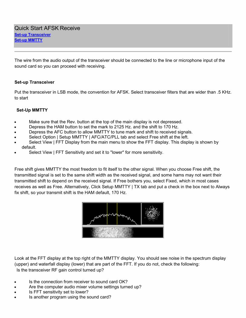
Look at the FFT display at the top right of the MMTTY display. You should see noise in the spectrum display
(upper) and waterfall display (lower) that are part of the FFT. If you do not, check the following:
Is the transceiver RF gain control turned up?
• Is the connection from receiver to sound card OK?
• Are the computer audio mixer volume settings turned up?
• Is FFT sensitivity set to lower?
• Is another program using the sound card?

Quick Start AFSK Transmit Set-up Transceiver
Set-up MMTTY
Transmit
Once you have made the connections to your transceiver audio input, you should be able to transmit audio
generated by MMTTY to the transceiver. Quick Start AFSK Transmit tells you how to set-up MMTTY for
simple operation. AFSK transmit operates by sending an audio signal from the computer sound card to the
microphone input of an SSB transmitter.
Set-Up MMTTY
When you are not transmitting characters, your transmitter should indicate to the receive station that you are
still in transmit mode. The convention is to "diddle" by sending a string of LTRS shift commands until there are
actual letters to transmit. Set diddle by doing the following:
1. On the main menu at the top, click Option | Setup MMTTY | TX tab. 2. On the TX tab, at the left, in the DIDDLE block, select LTR to choose the LTRS shift. 3. Below this, make sure that the Random and Wait Timer buttons are not selected.
4. Set unshift-on-space (UOS) in the TX block. Select only UOS and none of the other buttons.
In the Macro block, make sure that your callsign is correct in the Your Callsign window.
Click OK to close the display and return to the main MMTTY display. In the main display, at the left, in the
Control block, the UOS button should be down and all the other buttons should be up.
In the Demodulator block to the right, click the top six buttons so they appear to be up, and click the HAM
button at least once to set the Mark to 2125 and shift to 170.
Below the green squelch indicator bar, press NET to cause MMTTY to transmit where it last received. Press
AFC button to turn on automatic frequency control, so MMTTY can change its mark frequency to tune in a
received signal exactly.
Set-Up Transceiver
Since this is the Quick Start procedure, we use the easiest method of PTT control. Enable your transceiver
VOX, and adjust it so it turns on when the transceiver gets audio from the computer, and goes off when there
is no more audio. Control the transmit audio signal using the Transmit function discussed in the next section of
this topic.
If you do not have VOX, the next simplest approach is "two-switch operation," in which you first operate an
external PTT switch to turn on the transmitter, and then operate the MMTTY's Transmit function as shown
below. You must manually turn off the PTT after each transmission.

If you want PTT switching using radio control through a serial connection between your computer and radio, or
if you want to operate the transceiver PTT using a serial port, see Transmit and Receive Control (PTT).
Make sure that your microphone is out of the circuit when you start to operate RTTY.
Transmit
To transmit, press the red TX button at the left and type on your keyboard. Your typed characters first appear
in the lower window, the Tx window. As characters are transmitted, they appear in the upper window, the Rx
window.
To end transmission, press the TX button again. MMTTY finishes transmitting the typed characters, while the
TX button displays a WAIT message. When all characters in the TX window are sent, the button pops up and
again becomes the normal TX button. This is the usual way to end your transmission and go to receive mode
to listen to the other ham.
To end transmission immediately, press the button below the TX button, labeled TXOFF. This is the "panic
button" to turn off transmission right away.
Vista Issues
MMTTY has been updated by Dave Bernstein, AA6YQ to operate in Microsoft Vista under certain carefully
controlled circumstances.
MMTTY must be installed in a folder other than C:\Program Files or MMTTY must be installed and run while
logged into the account named "Administrator." These issues are discussed in articles at:
http://www.dxlabsuite.com/dxlabwiki/InstallVista and http://www.dxlabsuite.com/dxlabwiki/RunningOnVista
The other issue with Vista is soundcard assignments. Unlike previous versions of Windows that base
soundcard access on the card, Vista treats to each individual soundcard input and output as a separate
device. This often results in asymmetric soundcard configurations - particularly in systems with more than one
sound card.
Beginning with version 1.66, MMTTY includes the ability to specify the Transmit and Receive device ID
independently. In addition, the SoundCard tab provides a list of all available audio inputs and outputs.
Selecting the input/output will configure MMTTY's input and output.

Main Display
This topic discusses the main display for MMTTY, and points to other topics that discuss the software
capabilities in greater depth. The following items are presented:
• Main Menu
• Control Panel and FFT and XY display
• Logging Menu
• Receive Window
• Transmit Menu
• Transmit Window
Each of these items is a separate topic below Main Display. The FFT and XY display topic is under Control
Panel.
Main Menu
File Menu Items
Edit Menu Items
View Menu Items
Option Menu Items
Profile
Help
The main menu is the Windows menu at the top of the MMTTY display, with the terms File, Edit, View, Option,
Profiles, Program, Help. Each of these terms is a menu item, and we present each of them here.
The letter in parentheses next to each menu item represents a keyboard ALT- shortcut. For example, if you
press ALT-O, the options menu appears. However, MMTTY allows reassignment of the ALT shortcut keys, and
ALT-F has already been reassigned, so it does not bring up the File menu, it brings up the callsign list. See
how to change these assignments in the topic Keyboard Shortcuts.
Some options are only available after you have performed other actions.
In the tables below, some links bring up a full discussion of the operation on the left side, while others simply
show the MMTTY display under discussion.

File Menu Items
Log Rx File Begin a procedure to record the characters that appear in the Receive
window. Receive Window
Options of Received-log Specify the location of the receive log and choices about recording the
time that a received transmission starts.
Send Text Send a text file, to be named in the next screen.
RxWindow to File Save the contents of the Receive window to a file to be named on the
next screen.
Open LogData File Specify the logbook and open it. Logging
Save Data now Save data that are in the log window. Choice is gray until there are
unsaved data in the log window.
Record WAVE (mmv) immediately Record a representation of the incoming audio, saved as a wave file with
the extension mmv, instead of wav. Name it later. Record and Play Wave
Files
Record WAVE (mmv) as... Record the incoming audio, but first assign a name to the file. Record
and Play Wave Files
Play WAVE(mmv) Play the recorded wave file from the beginning. Record and Play Wave
Files
Seek Play position Move within a wave file. Record and Play Wave Files
Rewind Play/Record Return to the beginning of the recorded wave file. Record and Play Wave
Files
Pause Play/Record Stop playing the recorded wave file, but stay at this position in the file.
Record and Play Wave Files
Close Play/Record Stop playing the recorded wave file and close it. Record and Play Wave
Files
Exit MMTTY Standard Windows exit.

Edit Menu Items
Paste to TxWindow Paste previously copied text into the Transmit window for transmission.
Edit Macro Buttons Bring up the MMTTY setup screen at the Tx tab where the control panel macro
buttons are assigned. TX Tab and Macro Buttons and Macro Command List
Edit Messages Select and change messages stored as CTRL- and ALT-assignments.
Assign ShortCut Keys Change the assignment of CTRL- and ALT- letter or number keyboard shortcuts.
View Menu Items
Control Panel Make control panel appear and disappear. Control Panel
Control Panel size Resize control panel.
Macro Buttons Toggle macro buttons between keypad and linear display. Macro Buttons
FFT Display Make FFT signal display appear and disappear. FFTand XY Displays
FFT Width Select FFT bandwidth. FFTand XY Displays
FFT Sensitivity Vary FFT sensitivity, low is more sensitive. FFTand XY Displays
FFT Response Vary FFT response speed. FFTand XY Displays
XYScope Make RTTY crossed-ellipsis oscilloscope display appear and disappear. FFTand
XY Displays
XYScope Size Vary scope size within FFT display area. FFTand XY Displays
XYScope Quality Vary sample size of XY scope.
Scope Show a large-size amplitude vs. time scope display. FFTand XY Displays
Clear Rx Window Clear the receive window (upper window). Receive Window
Show Button Hint Some buttons have popup hints when the cursor is on them.
LogData List Edit the current logbook entries. Logging
Current QSO Data Edit data to be logged for the current QSO. Logging

Option Menu Items
Soundcard output level Bring up sound card mixer software for output.
Soundcard input level Bring up sound card mixer software for input.
Test A test string is run through MMTTY and appears in the receive
window, but nothing is sent through the sound card.
Disable transmission Do not allow transmission, despite buttons or commands.
Way to send Transmit letter, complete word, or complete line. Transmit
Window
Autosend CR/LF with TX button Transmit a CR/LF as soon as transmission begins.
Word wrap on keyboard Keep the letters of a word together if the end of the line would
split them.
PTT timer Set the maximum time of a transmission. Check mark disappears
if you set this to 0.
Running mode Start/stop running mode, which is set-up in the Logging option.
Contest Operation and Logging
Setup TNC emulation MMTTY operates as if it were a TNC, passing decoded audio
from a transceiver to another computer. Use MMTTY As a Modem
Setup Logging Set-up automatic logging features. Contest Operation and
Logging
Setup MMTTY Change most parameters of MMTTY reception and transmission.
Set-Up MMTTY
Profile
Profiles are discussed in their own topic, Profiles. When you select a profile, a number of parameters may be
changed to make MMTTY more suitable for that profile.
Note that the first profile is Standard RTTY. If you make changes to some parameters while you are learning
about MMTTY, and then find that you have messed up something important, click on the Standard Profile to
return to the way things were. Do not change the Standard RTTY profile until you know what you are doing.
Help
The Help choice leads you to a number of Help alternatives.

Control Panel
The Control Panel is the entire top of the MMTTY display. There are menu items to turn it on and off and resize
it in the View menu. It consists of the following components, seen from left to right at the top of the display,
each of which is described in its own topic:
• Control Buttons
• Demodulator Controls
• Control Buttons and Squelch Display
• Demodulator Buttons and Squelch Display
• Macro Buttons
• FFT and XY Displays
Control Buttons
FIG Button
UOS Button
TX Button (F9 key)
TX OFF Button (F8 key)
There are four Control Buttons at the far left of the top of the display:
• FIG • UOS
• TX
• TXOFF
Fig Button
The FIG button controls the LTR/FIG shift, and is under both operator and program control. In RTTY, letters
and figures share the same codes. The difference between them is whether the transmitting station sent a LTR
shift or a FIG shift character before sending the character code. Once a LTR or FIG shift character is sent, it
remains in effect until the other shift character is sent.

When MMTTY receives a FIG shift character, the FIG button goes down and the print comes out as figures or
punctuation. When MMTTY receives a LTR shift character, the button comes up and the print is letters. If
MMTTY ends up in the wrong shift, you can press the FIG button to change it from FIG to LTR or LTR to FIG.
MMTTY deals with the LTR/FIG shift in a number of ways, see Tx Tab , Receive Window , and the next
section, UOS.
UOS Button
UOS stands for Unshift-On-Space, and it is under operator control. When the receive station is receiving and
decoding characters, MMTTY may miss a LTRS or FIGS shift character. When UOS turned on, MMTTY shifts
to LTRS as soon as it sees a space.
After characters have printed, MMTTY can reverse LTRS/FIGS--put the cursor on the word to change, and
right-click .
Here are two reasons for UOS:
1. Most of what you receive in RTTY is letters, so if the program is unsure where it should be, it should use LTRS shift.
2. There is a RTTY convention that transmitting programs send a FIGS shift character whenever they are about to send FIGS, and repeat this FIGS shift after every space. However, it is not standard to send a LTRS shift after each space in word text, so if you accidentally end up in FIGS shift, there is no LTRS shift after the next space to bring you back to LTRS. The default is to return to LTRS unless the sending station tells you to go back to FIGS.
For most RTTY operators, the usual setting for UOS is on.
TX Button (F9 key)
Press the TX button to begin transmission. MMTTY operates PTT or sends a transmit command, and begins
to diddle or sends what is in the transmit window.
The TX button remains down during transmission. When you are finished typing or selecting text to send, press
it again. MMTTY stays in transmit mode until sends everything in the transmit buffer. During this time, the TX
button shows the message WAIT , to show you that MMTTY recognized your button press, but it is finishing
the job of sending. When transmission is complete, the RTTY audio stops, PTT switches to receive or a
software command is sent to put the transceiver into receive mode, the Wait button pops up and changes back
to TX.
TX is the transmit/receive button to use most of the time during a QSO.
MMTTY comes with the TX button assigned to the F9 key on the keyboard.

TX OFF Button (F8 key)
The TXOFF button stops transmission immediately. Remember this button if something bad happens to your
transceiver.
MMTTY comes with the TXOFF button assigned to the F8 key on the keyboard.
Demodulator Controls
Mark
Shift
Baud Rate
AV or LPF or Loop
The four windows at the left in the picture below, are the Demodulator Controls for an IIR demodulator.
Mark
The Mark window shows the mark tone audio frequency. In the above picture it is 2125, the HAM default
value. This value changes under software control when the AFC button is pressed, depending on the selection
in the Option | Setup MMTTY AFC/ATC/PLL tab . You can select a mark frequency by clicking the arrow to the
right of the mark frequency, or you can change the value in the window once you click the arrow.
Shift
The Shift window shows the amount of audio frequency shift (frequency difference) between mark and space
tones. Like Mark, it can vary when the AFC button is pressed, depending on the selection in the Option | Setup
MMTTY AFC/ATC/PLL tab. In addition, each time you click the word Shift it steps through its stored values.
Shift can also be selected with the arrow or changed after you click the arrow.

Baud Rate
Baud rate selector. Almost all ham RTTY is at 45.45 bauds. This is a multifunction display that shows more
than one value:
• If the demodulator is IIR, then clicking the word Baud changes the display to BW, or bandwidth. • If the demodulator is FIR, the terms are Baud and Tap. • If the demodulator is PLL, the terms are Baud and VCO.
AV or LPF or Loop
This is another multifunction display:
• If the demodulator is IIR or FIR, the terms are AV or LPF. • If the demodulator is PLL, the term is VCO.
Demodulator Buttons and Squelch Display
Type Rev. HAM
SQ Not. BPF
ATC NET AFC
The nine buttons to the right, in the screen shot below, are the Demodulator Buttons, and the squelch display
is between the second and third row of buttons.
Type of Demodulator
Each time you press the Type button, the Demodulator steps through its choices: (1) IIR, (2) Fir, and (3) PLL.
The Demodulator type changes, and the demodulator controls change as well.
The default demodulator is IIR. The PLL demodulator takes very little CPU power, so if you are using an old,
slow computer, you may want to try this demodulator.

Rev. (Reverse)
Rev. Toggles between regular and reverse shift. In regular shift, if you set your transceiver to LSB, the mark
tone is high and the space is lower than the mark by the amount of the Shift. In Rev. shift, the mark tone is low
and the shift is up, causing space tone that is higher in frequency than the mark tone.
HAM
The HAM button is useful after you have copied someone for a while with AFC on, and want to tune for others.
Here is how it works:
1. Set a default mark and shift value in Options | Setup MMTTY Demodulator tab. 2. Press the HAM button, and the Mark and Shift windows change to the HAM default values.
Once the default mark and shift values are set, they need not be changed.
The HAM default values for mark and shift can be changed on the Demodulator Tab.
The HAM button also restores encoding and decoding to Baudot RTTY values, specified on the Decode Tab.
These default values for the HAM button cannot be changed. When you press HAM, Baudot RTTY is restored.
SQ
SQ stands for squelch. Use the squelch to prevent MMTTY from printing random characters based on noise.
Here is how it works:
• Look at the horizontal indicator below the SQ button. This is the squelch indicator, or signal-strength indicator..
• There is a small vertical line in the bar, this is the squelch threshold. • The squelch threshold can be moved by placing the cursor to the right or left, and clicking. The bar
moves toward the cursor. • Audio signal strength is shown by how far to the right the green bar extends. • When the signal strength is greater than the squelch threshold, MMTTY decodes the signal and
prints, but if it is below threshold, MMTTY does not print.
You can turn off the squelch if you are trying to decode a weak station and are willing to accept noise printing
in order to catch meaningful copy as well.

Not.
Not. turns on the DSP audio notch filter. You can use this feature to null out a nearby mark or space signal, or
a tuner-upper. Here is how it works:
1. The notch can be adjusted on the Option | Setup MMTTY Demodulator LMS/NOTCH tab. 2. The Not. button turns on the notch capability, but when you first turn it on, the notch does not
......appear. 3. Put the mouse cursor on the FFT display to the far right, and right-click. A small triangle will appear
......at the cursor location. This is the notch center. The notch can be moved around using point and
......click. 4. To remove the notch, press the Not. button again. The next press of Not. will cause the notch to
......reappear.
You can set two notches on the Option | Setup MMTTY Demodulator LMS/NOTCH tab. The tabs alternate with
clicks. That is, set the first tab with a right-click, and the next right-click sets the second tab, while the first one
stays in place.
Here is a display of two notches. Each triangle indicates the center of the notch filter. Note that the signal is
strongly attenuated at that point.
Note: A left-click of the mouse cursor moves the passband, while a right-click sets the notch.
BPF
BPF stands for bandpass filter. It can be adjusted at Option | Setup MMTTY Demodulator BPF tab. This DSP
filter is centered on the middle of the bandpass shown in the FFT, so all you do is turn it on and off. The usual
setting for BPF is on, so MMTTY can decode well in the presence of an interfering signal.
ATC
ATC stands for Automatic Threshold Control. This DSP function adjusts the signal input level of the
comparator. The reason for including an ATC switch is that the ATC may not work well for low signal levels, at
which time you may want to turn it off. ATC can be adjusted at the Option | Setup MMTTY AFC/ATC/PLL tab.

NET
Normally, without the NET button pressed, MMTTY transmits with a mark tone at the HAM default audio
frequency, no matter where the AFC has put the receive mark audio frequency. When you press NET the
transmit mark frequency becomes the same as the receive mark frequency, and you will transmit right where
you last heard the other station. Some hams do not realize this, and find that other hams keep telling them that
they are off frequency, because they used AFC without NET.
The above holds only for AFSK, where MMTTY controls the transmit tone frequency. In FSK mode, NET has
no function.
AFC
AFC stands for Automatic Frequency Control. When this button is pressed, MMTTY varies the receive mark
frequency and shift width to adjust to the received signal. When AFC is pressed, you can tune close to a RTTY
signal, and in a second or two it is tuned perfectly. You can determine what can be varied automatically in
Option | Setup MMTTY AFC/ATC/PLL in the box labeled "Shift." This is dealt with in the topic Set-Up MMTTY.
Macro Buttons
Below is a screen shot of the Control Panel Macro Buttons. These are 16 easily-accessible buttons
programmed to simplify RTTY transmission.
Some buttons are already programmed with handy sequences, but all can be reprogrammed. To use one of
these buttons, put the mouse cursor on the button and left-click. To program one of these buttons, put the
mouse cursor on the button and right-click.
The buttons can send text or perform software operations. The Macro Command List topic has the software
codes to program these buttons. Everything you enter is either software code or text to be transmitted.

FFT and XY Displays
FFT Display
XY Display
Waterfall Display
FFT/XY/Waterfall and Processing Power
Just below is a picture of the FFT and XY displays. The FFT display is comprised of the spectrum display at
the upper left plus the waterfall display below. The XY display is to the right.
FFT Display
The FFT Display shows frequency across the horizontal axis and amplitude vertically. You can move around
the full audio by putting the mouse cursor on the FFT display and left-clicking. MMTTY centers the spot you
click in the audio passband. If AFC is on, a click between the mark and space signals should bring MMTTY
close enough to automatically tune in the signal in a second or two. This is the way most MMTTY users tune in
signals. It is also possible for you to turn off AFC and tune your radio so the mark and space signals are on the
two lines.
XY Display
The XY display is a computer representation of the oscilloscope crossed-ellipses display that used to be the
way RTTY signals were tuned, in the days of TUs and oscilloscopes.
For perfect tuning, one ellipse should be vertical, the other should be horizontal. If they are not at exact right
angles, this means that the receive shift is different from the transmit shift.
Waterfall Display
Some hams like the waterfall display that has become popular for PSK31. MMTTY offers a waterfall that is
directly lined up with the spectrum display above it. You can use this display to tune your radio, rather than use
AFC.

FFT/XY/Waterfall and Processing Power
FFT, XY display, and waterfall require many CPU calculations. If your computer stops working when you are
using MMTTY, or if it occasionally freezes, it may be that these operations are using more CPU time than you
can afford. To reduce the demand on your CPU, turn off the FFT and waterfall or the XY display. You can also
reduce sensitivity, response speed, and quality to reduce demand on the CPU without losing the function. The
solution is to use different combinations until you can live with the result.
A faster computer is another solution to these problems.
Logging Menu QSO Button
Data Button
Init Button
Call Button
Call Window
Find Button
Name Window
My(RST) Window
His(RST) Window
Frequency Window
Logging Topic
This is a picture of the logging menu. It is split into right and left halves to improve resolution in this Help file.
Left half of logging menu.
Right half of logging menu.
The logging menu works with MMTTY's built-in logging program, as well as with MMTTY's contest features.
Here are the items in this menu.

QSO Button
The QSO Button can work with Contest mode, where you will indicate what you want it to do on the first,
second, and third press, in Running Mode or S&P Mode. Set this up in Option | Setup Logging, where you will
need to make several entries.
If you turn Contest Mode off (Option | Setup Logging | Input Tab) then the first press of this button does
nothing, while the second press enters the data from the menu into the log as a QSO and then clears the
logging data windows.
Data Button
Press the Data Button to view and edit the complete set of data for the current QSO, before it is entered into
the log.
Init Button
Press the Init Button to clear the Call, Name, and My windows so you can start over.
Call Button
Click this button to switch between Running Mode and S&P mode when in Contest mode.
Call Window
If you put the cursor on something in the MMTTY receive window and left-click, text will appear in the call
window. When you are ready to call a station, click on his callsign and it will go into the call window (see the
Receive Window topic).
If this callsign is already in the log, the operator's name will appear in the Name window if you entered it in the
last QSO. Click View | Current QSO data to see that other data (name, QTH, remarks, QSL info) are copied
from the last QSO.
Find Button
Once there is a callsign in the Call Window, a press of the Find button will search the MMTTY logbook for
other contacts with this station.
Name Window
Put the other operator's name here. The second time you left-click the mouse, whatever is underneath the
cursor will go here. Once you have a call in the Call Window, If you put the cursor on the other operator's
name and left-click, it will go into the Name Window.
This window has a second function. If you click the work Name it becomes QTH, and the window is again
blank. The QTH function now takes the place of the Name function in the mouse-click logging sequence.

My (RST) Window
You can enter the RST report that you receive in the My(RST) Window, or simply select it from the drop-down
menu. You can set 599 as the default for My(RST). Click Option | Setup Logging | Input tab; check the box in
the middle of this tab that says 599 Default for MyRST.
His (RST) Window
This is the RST that you send. This value is 599 by default, but you can use the menu to select another report,
or type it in.
This window works with contest mode, to store information that is sent automatically with the QSO button. See
the topic Input Tab that is under Prepare for Contest Mode.
Frequency Window
If your transceiver is in communication with your computer, and you set this up in Option | Setup MMTTY |
Misc tab | Radio command button, then MMTTY automatically reads your receive frequency from your
transceiver and puts it in the Frequency Window.
If your transceiver does not communicate with MMTTY, you can select a frequency or type it in.
Note: If you have turned on Radio command, and then lose communication with the radio, you cannot select a
frequency in this window. Go back to Radio command, clear the name of the radio, and you again can enter a
frequency in the Frequency Window.
Receive Window
Log Data With a Mouse Click
Save Received Data
Right-Click for LTR/FIG Shift
Time Stamp
Clear Receive Window
The Receive Window is the large window just below the logging menu. Received text prints in this window.
The window has a memory for data which have scrolled up out of view, and you can use the scroll bar at the
left to see these data.
Log Data With a Mouse Click
If you Left-click some text in this window, the first click will be recorded as the callsign, and the second click as
a name. The third click is the same as the first, and so forth. If you change Name to QTH, as described in
Logging Menu, you can click the QTH into the log.
When you go to Contest Operation, you can input a received report plus serial number.

Save Received Data
You can save all the data that pass through the Receive Window in a file, limited only by the size of your
storage medium. Click File | RxWindow to file, and name the file. You can save an entire weekend contest this
way, so you have the original raw data to fill in your log if there was an error or data are missing. An estimate
by GU0SUP is that a weekend contest generates a file of 1 MByte.
No Other Copy Function
The procedure just described, mouse-clicks for specific data, or a screen capture with Print Screen or another
program, are the only way to save received data. There is no copy function for the Receive Window in MMTTY.
Right-Click for LTR/FIG Shift
If you accidentally receive data in the wrong shift, put the mouse cursor over each word, right-click, and the
characters will be printed in the other shift. In other words, if you receive a report of TOO, a right-click changes
this to 599.
Time Stamp
MMTTY can record the time of transmission and reception of each line that appears in the Receive Window.
Click File | Options of Received-Log | Time Stamp to begin recording a time stamp. Then Click File | Options of
Received-Log | Show time stamp in the Rx window to have this time stamp appear in the Rx window. You must
make both of these selections to get the time stamp to appear.
When you transmit, the time stamp for transmission only appears in the Receive Window when you send a
carriage return.
Clear Receive Window
Click View | Clear Rx Window to clear all data in this window.

Transmit Menu
Clear Button
Macro Buttons
Edit Window
Edit Button
Transmit Wait Adjustment
The area between the receive and transmit windows has a number of controls designed to make QSOs easier.
Here is the transmit menu; this example has already been changed from the one that comes with MMTTY. It is
split into left and right halves to improve clarity in this Help file.
Left half of transmit menu.
Right half of transmit menu.
Clear Button
The Clear Button at the far left clears the Transmit Window, just below the transmit controls. The keyboard
shortcut for Clear is F1.
Macro Buttons
The next four buttons are Macro Buttons, similar to the Macro Buttons on the Control Panel, but some of the
syntax for these buttons is different. A discussion of programming commands for all macros will be found in
Macros in the Macro Command List, or click Macro Command List for just the list of these commands. By
default, These three buttons are assigned to F2, F3, and F4.
Here is how to make a quick call to a DX station:
1. Mouse-click a call into the callsign field
2. Press F2 to set up a 1x1 call. 3. Press TX twice when you want to call.
This sends a quick 1x1 call and returns to receive when the call is complete. The two presses of TX start
transmission and then end transmission when the macro is finished.

Edit Window
The small window in the Transmit Controls is a drop down menu with more macros. If you select one of these
macros, the text appears in the transmit window and will be transmitted. Macro Command List is a list of
programming commands.
Edit Button
The Edit Button on this line allows you to change the contents of the macros in the Macro Window. Select
the macro and then press Edit.
Transmit Wait Adjustment
There is a transmit wait, or delay, control, that appears by default as "Both Wait" at the far right of the transmit
menu. The slider to the right controls the amount of time (wait) between transmission of characters. Select one
of four values by clicking the label.
• Disable wait - Slider position does not matter, there is no wait. • Char. wait - Delay character transmission. • Diddle wait - Delay diddle character transmission. • Both wait - Delay both character and diddle transmission.
See what this control does by disabling transmit and experimenting with it while listening to the sound card
output. Delay may help if you have a slow computer, or if the FSK modulator in your transceiver cannot
respond rapidly enough to characters as they are keyed by MMTTY and your computer.
Some of these parameters can also be set on the Tx tab. See TX Tab.
Transmit Window
At the bottom of the MMTTY display is the Transmit Window. Text appears here before being transmitted.
When you type in the transmit window, you can erase text until it is sent. This is one reason for selecting
Option | Way to Send as word out or line out. By delaying transmission, you gain time to make corrections to
the text.

Set-Up MMTTY
There is a set of screens that control many of the functions of MMTTY, on both transmit and receive. Click
Option | Setup MMTTY and there are six tabs, each of which has variables to set. The five tabs are:
• Demodulator • AFC/ATC/PLL
• Decode
• TX
• Font/Window
• Misc
• SoundCard
Each of these is discussed in its own topic.
At the bottom of the tab display are buttons that remain present for all tabs:
• HAM - The same as the one on the control panel. Sets mark and shift values to the default. • Set Default Demodulator - Changes to the default demodulator. • ? - Brings up a Help screen. • OK - Saves changes to all tabs and closes all tabs. • Cancel - Closes all tabs without changes.
Demodulator Tab
Discriminator
- Type
- IIR Resonator Settings
- Mark and Space
- Bandwidth
- Show
Limit Amp
Smooth LPF
Pre-Filter
Rev. and HAM Default
The Demodulator Tab is concerned with receiving and decoding RTTYsignals. Click Option | Setup MMTTY
and then click on the Demodulator tab if it is not already showing.
MMTTY gives hams a flexible DSP tool to decode RTTY signals. Because of its experimental nature, many
parameters of the demodulator can be changed. The ham community, by experimenting with these values,
may arrive at combinations that are suitable to different conditions. This Help file specifies arbitrary default
values used by MMTTY to create an operating RTTY decoding system. You may find that you can improve
performance by changing them.

It is beyond the scope of this Help file to explain all the variables on this tab, but we attempt to point you in the
right direction for most of them. Read the Demodulators topic for an overall explanation.
Here is a picture of the Demodulator tab.
Discriminator
Type
At the left is the discriminator block, where you choose the type of DSP discriminator MMTTY uses. There are
three discriminators from which to choose:
• IIR Resonator • FIR BPF
• PLL
The default discriminator is IIR Resonator. If the discriminator changes, some of the possible settings for the
discriminator change. This is reflected in a change in the label and function of some of the windows in the
Demodulator area of the main display and below the discriminator choice.
IIR Resonator Settings
Mark and Space
For the IIR Resonator discriminator set Mark, Shift, and bandwidth (BW).

IIR Bandwidth
Bandwidth sets the width of the DSP discriminator. The default is 60 Hz.
Show
Press the Show button to see how MMTTY has shaped its bandwidth using your mark, shift, and BW or other
settings, along with the demodulator you selected.
Limit Amp
The AGC box turns on AGC at the limit amplifier. See the topic Demodulators.
The Nyquist frequency is twice the frequency of the fastest waveform. It is necessary to sample above the
Nyquist frequency in order to fully reconstruct the signal. Therefore, the sampling frequency is the ratio of how
many times above the highest frequency is the current frequency. Oversampling requires more computer
power (and speed) than not oversampling, but more accurately reproduces the input signal.
Smooth LPF
You can select whether the smoothing LPF (the Output LPF in the diagram of a PLL demodulator in the
Demodulators topic), is an FIR or IIR circuit. You can select the LPF cutoff frequency and also select the order
for an IIR filter. The higher the order of the filter, the sharper (steeper) is the filter cutoff. If these filters were
passive, it would be as if you had added additional LC components to the filter. A higher order filter takes more
processing power.
Pre-Filter
Before the received signal reaches the demodulator, MMTTY applies a DSP Pre-Filter to it. The controls in
this section customize the pre-filter, and the show button shows you the result of pre-filtering. The pre-filter can
do three jobs:
1. It can reduce noise with an LMS adaptive filter. 2. It can remove interfering signals (heterodynes) with a Notch Filter. 3. It can shape the received bandwidth before the signal reaches the discriminator.
The above functions are partly controlled by buttons and other operations on the main display. The On box of
this tab changes if you click it here or if you use the BPF or Notch buttons on the main display. If you set notch
off, the main display no longer has a Not. button, it has an LMS button. MMTTY cannot have both notch and
LMS.
To work with LMS/Notch or with BPF, you must click on the appropriate tab.

BPF
The prefilter includes a bandpass filter whose width can be varied, and which can be turned on and off here or
on the control panel.
• Increasing the number of taps increases the skirt steepness of the filter. • Increasing FW widens the bandpass of the filter for signals less than 6 dB, but also decreases the
response to weaker signals outside the main bandpass. • The default values are Tap = 56 and FW = 100. • Vary these values and use the Show button to see the result for the BPF.
LMS
LMS is an adaptive filter that can reduce the effect of noise (QRN) on the signal using autocorrelation. Signals
have high autocorrelation over time (once a signal starts, it will be there a few milliseconds later) while noise
has low autocorrelation. There are tricks that can be used to decrease the time autocorrelation of noise. If DSP
is used to amplify signals with high autocorrelation, the result is amplification of signal and non-amplification of
noise.
Uncheck the box labelled Notch to use LMS. You can have only LMS or notch, not both. When you do this, the
Not. button on the control panel becomes LMS.
Four LMS parameters can be set:
• Number of taps • Autocorrelation delay • 2u (the character is the lowercase Greek letter upsilon) • Gm.
Notch
Once you select Notch to turn it on, the LMS display disappears (and the LMS button on the control panel
becomes Not. You may select one or two notches, and you may set the number of taps (default = 72). More
taps take more cpu power. See the FFT and XY Displays topic to learn how to control the notch once you have
turned it on.

Here is the Notch tab within the Demodulator tab, showing how to turn on two notches.
Rev. and HAM Default
Reverse
The Reverse check box reflects the position of the Rev. button in the control panel. Check Rev. to reverse the
mark and space frequencies.
HAM Default
Use these windows to change the mark (left window) and shift (right window) frequencies for the HAM button.
This change holds until it is changed here again. When you press the HAM button, these frequencies are the
ones that appear in the mark and shift windows on the control panel.

AFC/ATC/PLL Tab
AFC Block
ATC Block
PLL Block
Here is the AFC/ATC/PLL tab.
AFC Block
At the left is a block called AFC.
AFC
The AFC check box reflects the position of the AFC button on the control panel.

Shift
When you turn on AFC, there are two parameters that can be adjusted to tune in the other station exactly: (1)
mark frequency and (2) shift width or distance of the space frequency from the mark frequency. The Shift
parameter sets how these can vary:
• Free - Mark frequency and shift width are both free to change, and MMTTY will try to match the other signal exactly. This is the most flexible setting, but it can result in a transmitted signal that does not fit a standard.
• Fixed - Mark frequency can change, but the shift width must remain at its current setting. This assures that when you transmit using AFSK, you will always transmit a set shift width, and most hams use the HAM button to set this to 170 Hz..
• HAM - Mark frequency and shift width can change, but the shift width must take on one of the standard HAM values of 170/200/220/240 Hz. MMTTY decides among these and chooses the one that works best, but if you check HAM, you will never transmit a shift width other than one of these standards. This is a little more flexible than Fixed, but still assures that your transmission will fit a standard shift. If someone were to observe your signal on another receiver, it would fit standard parameters, because they cannot tell your transmitted mark frequency, but they can see your shift width.
• FSK - Mark frequency cannot change and the shift can only take the values of 170/200/220/240 Hz., whichever works for most letters decoded. This approach makes MMTTY work as if you were using FSK modulation in your transceiver, even though you are transmitting AFSK. If you had an FSK modulator, MMTTY would not be able to change its mark frequency. You must tune in every station completely, the AFC button can only vary your shift. This is the least flexible setting, close to turning off the AFC.
Time
Time sets the time it takes for full ATC action. The shorter you set this value, the faster the ATC operates. The
default value is 8. This window actually sets the number of samples required to compute the threshold.
SQ
SQ stands for squelch. The squelch controls the value that the AFC will accept to try to lock in. The default
value is 32.
AFC SQ is not the same as the squelch on the control panel. The control panel squelch display controls
how strong a signal must be to print. The AFC SQ setting controls how weak a signal the AFC will use to tune
in.
If you set SQ too high, you will not tune onto weak signals. If you set it too low, the AFC may tune into random
noise or a weak signal or tone rather than a signal.
Sweep
Sweep sets how far the AFC will follow the target signal. Frequency that MMTTY will follow a target signal =
shift width x Sweep. The default value is 1.

ATC Block
ATC (Automatic Threshold Control) adjusts the input level to the comparator in accordance with the strength of
the input signal.
The ATC check box reflects the position of the button on the control panel.
Time specifies how many recent signal samples are used to compute the input level threshold. The more
samples, the more slowly will ATC change the input level. The default of 4 is a relatively small number of
samples, and MMTTY will quickly respond to an echo. However, you may want to experiment with this value
under different conditions.
If conditions are good, you may get better decoding with ATC off.
PLL Block
To use PLL as a demodulator, it must be selected on the Demodulator tab or on the control panel.
VCO Gain
VCO Gain can be varied from the control panel when PLL is selected as the demodulator. This window reflects
what is in the control panel.
The default value is 3.
Loop LPF (IIR)
The LoopLPF is part of the demodulator circuit, and it is a low-pass filter. Its parameters can be set here.
Order
FC
FC is the low pass filter cutoff frequency.
f Button
Press the f Button to see a prediction of the shape of the Loop LPF.
Output LPF (IIR)
Order
FC
f Button
Press the f Button to see a prediction of the shape of the Output LPF.

Decode Tab
Baudot RTTY Default
Default Rx Stop Bit Block
Baudot Codeset
Ignore Framing Error
The Decode tab shows parameters that control the way in which MMTTY encodes and decodes a RTTY
signal.
Baudot RTTY Default
The default for these values causes MMTTY to encode and decode Baudot RTTY. This is the RTTY code
used in most current ham radio RTTY operation. Here are the values:
Baud Rate:45.45
Majority Logic: checked
Ignore Framing Error: unchecked
Bit Length:5 bit
Stop Length: Rx = 1 bit, Tx = 1.5 bit
Parity: None
Default Rx Stop bit: Rx = 1 bit, Tx = 1.5 bit
Baudot Codeset: S-Bell
When you press the HAM button, Baud Rate, Bit Length, Stop Length and Parity values are reset to the above
defaults.

Default Rx Stop Bit Block
One of the Baudot RTTY defaults noted above can be changed--the Stop Length. The Default Rx Stop bit
controls the setting of the Stop Length when you press the HAM button. To make Stop Length become Rx =
1.42 bit, Tx = 1.5 bit when you press the Ham button, check this box in the Default Rx Stop bit block.
Baudot Codeset
There are two standards for the code to ring a bell on a mechanical RTTY teletype. The U.S. standard is FIGS,
S and the international standard is FIGS, J. You can select one here, but it is not usually important.
Majority Logic
Ignore Framing Error
RTTY is decoded in frames. A frame is defined or "marked off" by a start pulse, some code, and a stop pulse.
The sequence of bits between these two pulses defines the character that is decoded.
TX Tab
Diddle Block
Tx Block
- Digital Output
- Char. Wait and Diddle Wait
PTT Block
- Port Window
- Invert Logic
- Radio Command Button
TxBPF/TxLPF Block
Macro Block
Input Button Block
Radio Command

This is the TX tab. It has a great many controls on it, so this topic is quite large.
Diddle Block
Diddle is the modulation put out by MMTTY when there are no data to transmit. It tells the other station that
you are still there, and lets others tune onto you.
• None - MMTTY transmits a steady mark tone. • BLK - MMTTY transmits a string of the character for blank. • LTR - MMTTY transmits a string of the LTRS shift code. This is the standard diddle in ham radio. • Random varies the time between diddle characters in a random way. If random is not checked, the
characters are evenly spaced. • Wait reduces the time between characters during a random diddle. You hear more diddle
characters if wait is checked.

Tx Block
• UOS turns on Unshift-on-Space for transmitting. When you transmit a space, MMTTY also sends a LTR shift character.
• Double shift causes MMTTY to transmit two LTRS or two FIGS characters whenever one is called for, to lower the chance that the other station misses the shift. If the receive station receives one or both characters, it shifts properly.
• Disable wait eliminates the wait before a diddle character. It is the same as clicking the transmit wait adjustment on the transmit menu until it shows Disable wait.
• Disable Rev disables reverse on transmit, but the Rev. button still works for receive. This may be useful if for some reason your signal on transmit is upside-down from receive signals.
• Always fix shift causes MMTTY to transmit with the HAM shift, no matter how the receive shift is set.
Digital Output
Digital Output controls the volume of sound output from the sound card. You can also control this from the
Windows mixer volume control. Try to set this so you do not have to make mixer changes when you operate
MMTTY.
Char. Wait and Diddle Wait
The Char wait and Diddle wait controls are the same as those on the transmit menu of the main display. They
control the delay before regular data (char) or diddle characters are transmitted.
PTT & FSK Block
Port Window
The Port window selects which COM port is to provide FSK and PTT outputs. The DTR and RTS on this port
go high HIGH when MMTTY goes to transmit mode. If you select the same port that is selected in Radio
Command for communication to the radio, the Radio Command port is set to None, but you are not notified of
this. Be careful when selecting the PTT and FSK port so as not to erase that entry once you have made it.
Invert logic
The PTT line is operated by bringing the DTR and RTS COM port signals HIGH on transmit, and returning
them to LOW on receive. If you discover that your PTT line always seems to be keyed, check the Invert Logic
box to reverse the polarity, so MMTTY brings the DTR and RTS signals LOW on transmit and HIGH on
receive.
Radio Command Button
MMTTY can communicate with transceivers that have interfaces to a computer. Click this button to go to the
set-up procedure for Radio Command. Radio Command can do the following:
• Transceiver frequency can be displayed in MMTTY's frequency window on the Logging menu. • MMTTY can send a software transmit/receive command to the transceiver so you do not have to
hook up a wire to control PTT.
See the topic Radio Command to see how to set-up this feature.
TxBPF/TxLPF Block
These two check boxes control a transmit signal shaping filter. TxBPF is a bandpass filter, and TxLPF is a low
pass filter. You must decide for yourself whether you need these filters for clean RTTY transmission. Most
hams leave these boxes unchecked.
You can experiment with number of taps and, and press the f button to see the theoretical shape of the
transmission bandpass.
Macro Block
The callsign that is in the callsign window is the one that is used by the %m macro as your own callsign.
Assign the 16 control panel macros on this tab by left-clicking on a key and typing what you want it to do. You
can also do this on the control panel Macro keypad by right-clicking on a key. See the Macros topic for
information on how to program the keys, or click Macro Command List for just the list of commands.
Input Button Block
The four buttons in this block are the four Group 2 Macro buttons in the transmit menu. Left-click to edit them,
or right-click on the buttons on the transmit menu and edit them there.

Radio Command
Requirements
Set-up Radio Command
- CTS vs. XON/XOFF
Radio Command Cannot Share a Port
MMTTY can communicate with many transceivers over a serial port. Radio Command involves two software
actions:
1. Transceiver frequency can be displayed in MMTTY's frequency window. 2. MMTTY can send a software transmit/receive command to the transceiver so you do not have to
hook up a wire to control PTT.
Requirements
Your transceiver must have the capability to communicate with MMTTY over a serial port. This topic shows
how to set-up the serial port communication. You must know the data communications parameters for the
control port of your transceiver. In most cases, software handshaking (XON/XOFF) works OK. If you have an
Icom or older Ten-Tec transceiver, you need to know the transceiver's port address.
Once you have set-up Radio Command, directing MMTTY to transmit will send a software code to the
transceiver to put it into transmit mode.

Set-Up Radio Command
Here is the procedure to set-up MMTTY to communicate with the transceiver. This procedure requires software
codes specific to certain transceivers, and the information you need may differ among transceivers.
1. Click Option | Setup MMTTY | TX tab. 2. Press the button labelled Radio command. 3. At the top of this display, set-up the Port Definition commands. See the note below for an important
......warning. 4. Check the PTT box in DTR/RTS if you want hardware command of PTT on the Radio Command
......port. 5. If you do not want to control PTT with a hardware interface from the Radio Control port or want to
......control PTT on the same port as PTT, then uncheck this box. 6. If you want to use software commands to control transmit/receive switching, select the command
......protocol for your transceiver in the Group box at the bottom of the display. If your transceiver is not
......in the list and you know the correct commands, they can be set directly (using hexadecimal) in the
......Rx and Tx windows. The commands can be saved and reloaded using the Save and Load buttons
......at the bottom of the window. 7. To make the VFO frequency appear in MMTTY's frequency window, select your transceiver in the
......"Model" selector. 8. Polling interval sets how often (in seconds) MMTTY sends a command to the radio asking for
......frequency information. 9. Ten-Tec and Icom radios need an extra piece of information, the address of the radio. The default
......value for Ten-Tec is 04; Icom has a different number each model. 10. The frequency offset changes the displayed frequency in the frequency window. If you operate
......AFSK using LSB, set this to LSB and MMTTY's frequency window will show you where your mark
......tone transmits. 11. When you are done, click OK.
There is window for an initialization code (Init), but at present no radios need an initialization code.

CTS vs. XON/XOFF
The computer serial (COM) port communicates with the serial port of the radio to send and receive radio
commands. Sometimes one device (computer or transceiver) talks before the other is ready to listen. This flow
can be controlled in two ways: by additional software commands (XON.XOFF), or by hardware signals on pins
in the serial port (CTS or Clear to Send). Hardware command is more reliable, but some devices do not
support it.
Try using CTS first, and check to see if the frequency is displayed properly and that PTT via radio command
works well. If it does not, then try XON/XOFF. You can use both, but if one works well and the other does not,
it is safer to turn off the one that is less reliable.
Radio Command Cannot Share a Port
The radio command port cannot be shared with FSK. However, since MMTTY supports PTT via Radio
command, via DTR/RTS on the Radio Command Port or via RTS/DTR on the FSK port there is a great deal of
flexibility when configuring MMTTY.
Font/Window Tab
Adjust Block
Waterfall Block
XY Scope Block
Rx Window Block
Tx Window Block

The Font/Window tab allows you to adjust MMTTY's data windows and waterfall.
Font - selects the font for text in receive and transmit windows.
Slash Zero - causes zeros to be printed with a slash to distinguish them from the letter O.
Adjust Block
The default for these two settings is 0, which turns off adjustment.
Waterfall Block
• L - sets the background color of the waterfall display. Default is black. • H - sets the foreground color of the waterfall display. Default is white.
XY Scope Block
• The large square selects the foreground color of the XY display. Default is white. • Reverse rotation changes the direction in which the crossed ellipses to rotate with a .........
......frequency change.

Rx Window Block
• Back - sets the background color of the receive window.
• Char. - sets the color of received text characters.
• Char. sent - sets the color of transmitted characters printed in the receive window.
Tx Window Block
• Back - sets the background color of the transmit window. • Char. - sets the color of characters in the transmit window before they are transmitted. • Char. sent - selects the color of the characters in the transmit window that have been transmitted.
•
Misc Tab
Sound Card Block
- FIFO
- Priority
- Device ID
- Source
- Clock
Sound Loopback Block
Tx Port Block
System Font Block
- Window
- Fixed Pitch

Here is the Misc tab under the Setup MMTTY procedure.
Save Window Location
Check this box if you want MMTTY to remember its window size and location when it closes. It opens the same
way next time you start MMTTY.
Sound Card Block
The next two sections, FIFO and Priority, discuss adjustments to sound card operation. Changes to either
adjustment can result in transmit audio breakup. If you have a breakup problem, experiment with both
variables to determine how to fix the problem. Setting either adjustment too high can interfere with computer
operation.
FIFO
FIFO means "first in, first out," but it refers to the buffers that are used to hold incoming (Rx) and outging (Tx)
audio before it is processed. The default FIFO values are Rx = 12 and Tx = 4.
Priority
Windows can assign priority to various tasks that are running, and MMTTY assigns a high priority to sound
processing to generate the transmit audio. If it is set too low, the transmit audio breaks up, but too high can
mean that menu items take too long to appear or the cursor does not follow mouse movement because there is
no time left to do these tasks. The default priority is Higher.

Priority also affects the speed with which a command may be sent to the transceiver. If you are using Radio
Command to control T/R switching, and you feel that it takes too long to go into or out of transmit mode,
increase the Priority. The slower or busier your computer, the more important this selection becomes.
Device Identifiers
RX selects the sound card to be used for receive. TX selects the soundcard to be used for AFSK transmit. If a
particular sound card does not work with MMTTY, change the RX or TX identifier until the correct soundcard is
selected. Setting the ID to -1 will use the Default soundcard in Windows (the soundcard used for Windows
Sounds).
The SoundCard tab provides a list of all soundcards installed in the computer. Selecting soundcards for
Reception and Transmission on the SoundCard tab will set the RX and TX ID automatically.
Source
Most sound cards work in monaural mode, but some only work in stereo mode. If you have a problem, select
right or left channel of the sound card. This option is for receive only; the transmit audio comes out of both
channels of the sound card. The default is mono.
Clock
• The clock window shows the speed of the sound card that MMTTY thinks is right. • The default clock speed is 11025 Hz., and most sound cards are supposed to work at this speed. • The Adj. button begins a calibration procedure to discover the actual speed of the sound card. See
the topic Calibrate the Sound Card for instructions on how to calibrate the sound card. • Use Tx Offset if your sound card seems to operate differently on output (transmit) vs. input
(receive).
Sound Loopback Block
Sound loopback involves simultaneously running the record and play functions of a duplex sound card. Most
modern sound cards are able to support loopback, but not all cards can do this. Loopback is provided for some
advanced applications of MMTTY.
• Satellite communication
• Monitoring of FSK transmission
Off - No loopback. The receive demodulator does not operate during transmit. With no loopback the data that appear in the receive window as you transmit are taken directly from the transmit window.

Here is a block diagram.
Int. - internal loopback. In transmit, there is an internal path for the transmit signal to go to the receive demodulator. Internal loopback simply demonstrates that the software modulator is working, because the signal is taken from the modulator and demodulated.
Ext. (SAT) - external loopback. In transmit, the received signals from the sound card mic or line input are send to the receive demodulator for decoding. External loopback requires that you be able to receive during your transmission, which is often the case in a good satellite communication ham radio station. Tune in your received echo from the satellite, and the data from that echo appear in the receive window while you transmit. This can be confusing, because there is a two-way transmission delay before the letters appear.
If you select EXT (SAT), but do not have duplex receive and transmit capability, no transmit characters appear during transmission.
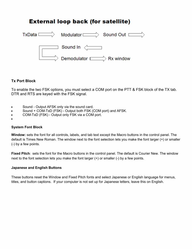
Tx Port Block
To enable the two FSK options, you must select a COM port on the PTT & FSK block of the TX tab. DTR and RTS are keyed with the FSK signal.
• Sound - Output AFSK only via the sound card. • Sound + COM-TxD (FSK) - Output both FSK (COM port) and AFSK. • COM-TxD (FSK) - Output only FSK via a COM port. •
System Font Block
Window: sets the font for all controls, labels, and tab text except the Macro buttons in the control panel. The
default is Times New Roman. The window next to the font selection lets you make the font larger (+) or smaller
(-) by a few points.
Fixed Pitch: sets the font for the Macro buttons in the control panel. The default is Courier New. The window
next to the font selection lets you make the font larger (+) or smaller (-) by a few points.
Japanese and English Buttons
These buttons reset the Window and Fixed Pitch fonts and select Japanese or English language for menus,
titles, and button captions. If your computer is not set up for Japanese letters, leave this on English.

SoundCard Tab
The SoundCard tab allows the user to select which Soundcard will be used for Reception and for AFSK
transmission.
Reception
The Reception box will provide a list of audio Input devices installed under Windows. Select the audio input
device connected to the audio output of your transceiver. Selecting an audio input device will set the RX
Device Identifier on the Misc tab.
Transmission
The Transmission box provides a list of audio Output devices installed under Windows. Select the Audio
output device connected to the audio input of your transceiver to be used for AFSK. Selecting an audio input
device will set the TX Device Identifier on the Misc tab.
Transmit and Receive Control (PTT)
One of the first operating functions most hams would like to automate is transmit and receive control; that is,
we all would like one-button operation (PTT, push-to-talk) to switch from receive to transmit and back again.
Here are alternative methods of PTT that are available for MMTTY users. In all cases, receive control is the
reverse of transmit.
• Two-switch operation. Press one button to get MMTTY switch and another button to get the ......transceiver to switch. Two-Switch PTT
• VOX controlled operation. The presence of an audio at the output of the sound card and input of the ......transceiver operates a VOX circuit in the transceiver. When MMTTY transmits, the VOX circuit ......senses this and puts the transceiver into transmit mode. When transmission ends, the VOX circuit ......senses this and puts the transceiver into receive mode. VOX Control of PTT
• PTT controlled by a serial or USB port in the computer. When MMTTY goes into transmit, it raises a ......pin voltage on the port, which tells the transceiver to go to transmit. PTT Using a Pin on a Serial ......Port or PTT With a USB Port
• Software control. MMTTY sends a software transmit command over a port to a transceiver that has ......a computer interface. The interface interprets this command and the transceiver goes to transmit. ......Software Control of PTT
The next topics show how to implement these PTT alternatives. Some of these alternatives are covered briefly in Quick Start and in Radio Command topics, but they are treated in depth here.
Two-Switch PTT
Two-switch PTT simply means that the computer does not control the transceiver. RTTY is a mode like a
ragchew in SSB, in which one person speaks, then the other speaks. If you are simply operating, and not
DXing or contesting, then you can operate the transmitter with a PTT switch and use the F9 key or the cursor
to get MMTTY to transmit or receive.
Put the transceiver into transmit first, so when MMTTY begins to send, the transceiver is already in transmit
mode. When going to receive, order is less important, but you must do things smoothly. When the other station
hears your signal end (no more diddle) then he or she will go into transmit, and you must have both your
transceiver and MMTTY in receive mode to print everything.
If you are thinking of using two-switch PTT, read the topic VOX Control of PTT. If you can use VOX, it is easier
to operate than two-switch.

PTT Using a Pin on a Serial Port Hardware Serial Interface
Software Set-up for Serial Control
USB Port
MMTTY can control PTT of a transceiver by operating a serial (COM) port as MMTTY goes into transmit or
receive mode. The circuit below interfaces the signal at the COM port to most transceiver push-to-talk (PTT)
interfaces.
There is an important limitation to this situation. There are three ways that MMTTY uses a COM port to
interface to a transceiver:
1. Control PTT
2. Key FSK
3. Send commands (PTT, polling) and receive information (frequency) from a computer-aided ......transceiver
MMTTY can operate PTT on either the Radio Control Port or the FSK & PTT Port. If your computer has only
one serial port and you are using AFSK, it is convenient to perform PTT on the Radio Control port. If you are
using FSK, it is most convenient to use the FSK port for PTT.
Hardware PTT Interface Between Computer and Transceiver
The circuit above interfaces a serial (COM) port (either 9-pin or 25 pin) to a PTT input. It is the same circuit as
the one shown in the topic, Prepare MMTTY for FSK.
You need only wire the RTS or DTR pin, not both.
If you have interference from the PTT line to the computer, add decoupling capacitors and ferrite beads or
cores.
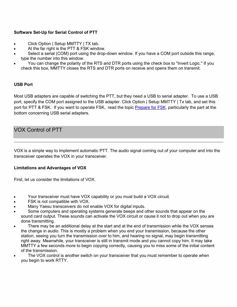
Software Set-Up for Serial Control of PTT
• Click Option | Setup MMTTY | TX tab. • At the far right is the PTT & FSK window. • Select a serial (COM) port using the drop-down window. If you have a COM port outside this range,
type the number into this window. • You can change the polarity of the RTS and DTR ports using the check box to "Invert Logic." If you
check this box, MMTTY closes the RTS and DTR ports on receive and opens them on transmit.
USB Port
Most USB adapters are capable of switching the PTT, but they need a USB to serial adapter. To use a USB
port, specify the COM port assigned to the USB adapter. Click Option | Setup MMTTY | Tx tab, and set this
port for PTT & FSK. If you want to operate FSK, read the topic Prepare for FSK, particularly the part at the
bottom concerning USB serial adapters.
VOX Control of PTT
VOX is a simple way to implement automatic PTT. The audio signal coming out of your computer and into the
transceiver operates the VOX in your transceiver.
Limitations and Advantages of VOX
First, let us consider the limitations of VOX.
• Your transceiver must have VOX capability or you must build a VOX circuit. • FSK is not compatible with VOX. • Many Yaesu transceivers do not enable VOX for digital inputs. • Some computers and operating systems generate beeps and other sounds that appear on the
sound card output. These sounds can activate the VOX circuit or cause it not to drop out when you are done transmitting.
• There may be an additional delay at the start and at the end of transmission while the VOX senses the change in audio. This is mostly a problem when you end your transmission, because the other station, seeing you turn the transmission over to him, and hearing no signal, may begin transmitting right away. Meanwhile, your transceiver is still in transmit mode and you cannot copy him. It may take MMTTY a few seconds more to begin copying correctly, causing you to miss some of the initial content of the transmission.
• The VOX control is another switch on your transceiver that you must remember to operate when you begin to work RTTY.

Now, let us consider the advantages of VOX:
• There are no wires between the transceiver and the computer other than the audio connection. • There is no programming to make VOX work.
How to Make VOX Work
• Set your transceiver so you are working into a dummy load, or set the output power to zero. • Connect the audio between the transceiver and the computer. • Set MMTTY to diddle, see Tx Tab. • Put MMTTY into transmit mode with the Tx button
• Adjust the VOX sensitivity of your transceiver VOX so the rig goes into transmit. • Put MMTTY into receive mode and make sure that the VOX goes off. • You may want to shorten the VOX delay. Make this judgment as you determine the interval
between pressing the button to go to receive mode and actually seeing the transceiver change modes.
Problems
If the transceiver fails to go out of transmit mode, the VOX sensitivity may be too high, or there may be
extraneous sounds from the computer going out the audio line.
If the transceiver jumps into transmit mode by itself, perhaps VOX is not the best way to operate. As a partial
solution, you can turn off VOX while you are in receive mode.
Software Control of PTT
The topic Radio Command discusses how to set-up MMTTY and your transceiver to operate software control
of PTT.
The transceiver must be capable of computer communication over a serial port. The transceiver and computer
are connected using this port, and MMTTY sends commands over this port to tell the transceiver to transmit or
receive. It also uses this port to get information from the transceiver about the frequency of the VFO, so this
can be displayed.
The only drawbacks to software control are: (1) if the computer crashes or hangs up while the transceiver is in
transmit mode, you must turn the transceiver off manually and then turn it back on; (2) the transmit/receive
change time is longer than using other methods; (3) if you have RF in the shack - even though it may not
cause problems with other modes - RF can cause the transceiver to miss the "Receive" command resulting in
a "stuck" transmitter. Time usually is not critical in RTTY applications, and it can be adjusted using the Radio
Command set-up.

PTT With a USB Port
The serial port is being replaced by USB ports in many modern computers. Since MMTTY can use a serial port
for FSK & PTT, the question arises about whether a USB port can be used for PTT. This can be done, but
only with a USB serial port adapter.
Don's (AA5AU) site, mentioned in connection with FSK via USB, is useful here:
http://www.aa5au.com/gettingstarted/rtty_start8.htm.
Most USB adapters work properly to allow serial port keying using DTR or RTS, described in the topic PTT
Using a Pin on a Serial Port. USB serial port adapters also appear to work for Software Control of PTT.
AFSK and FSK
MMTTY always receives using an audio signal into the computer sound card. However, MMTTY can transmit
using either AFSK, audio frequency-shift keying, or FSK, frequency-shift keying. The next topics discuss these
approaches and how to use them.
When you begin to plan your installation you will need to consider more than the choice between AFSK or
FSK. You should consider how your will control your transmitter (PTT) and whether you want to take
advantage of MMTTY's ability to read operating frequency (in supported transceivers) for computer logging.
Your specific configuration will depend on the computer control capability of your transceiver, the number of
available serial ("real" or USB) ports, whether or not you use a commercial interface and your personal
preference for AFSK or FSK. FSK and PTT can share one serial port. Radio control (CAT) and PTT can also
share a serial port. If you want CAT, FSK and PTT, your computer will need two serial ports.
AFSK
AFSK stands for audio frequency shift keying. Two audio tones are sent, in the right combination, to the audio
input of an SSB transceiver. Since the transceiver already transmits SSB, no further equipment is needed for
AFSK besides the transceiver and the computer with its sound capability.
Theoretically, if the carrier is fully suppressed and there is no audio distortion the signal generated by AFSK in
indistinguishable from one generated by FSK. On the other hand, it is not difficult to create distortion in and
AFSK system that generates a transmit signal that interferes with other stations.
When you use AFSK, MMTTY can be set up to exactly mimic an FSK transceiver or you can allow it to be
more flexible.

Reception
From the standpoint of MMTTY, AFSK is only a method of transmission. MMTTY always receives the same
way--by decoding audio from the transceiver.
Why Use AFSK?
There are some reasons to use AFSK, and here are a few.
• AFSK is simple. Other than audio in and out no special interface is required
• With AFC and NET enabled you will always transmit on the same frequency that you last heard the other station in the QSO.
Prepare for AFSK
AFSK stands for audio frequency-shift keying. Theoretically, there is no difference between a signal that is
generated by using a two-tone FSK modulator, and a signal that is generated by modulating a single-sideband
transceiver with two audio tones (AFSK).
MMTTY generates the two tones of AFSK using the computer sound card. Feed these into the microphone
(mic) input of a single-sideband transceiver to generate an AFSK signal.
A computer sound card typically generates an audio signal on the order of five volts AC, while the microphone
input of a transceiver is designed to accept an audio input of about 50 microvolts AC. The sound card signal is
therefore about 100 times higher in voltage than the transceiver needs. Because of this, you should use a
voltage divider between the output of the sound card and the input to the transceiver. Here is a schematic of
this 100:1 divider circuit.
Some transceivers already have a divider built into them. You should check the instruction manual for your
transceiver.
Most commercial "RTTY interfaces" or "digital radio interfaces" have such a divider in them.

Some transceivers have a special digital audio input at the rear of the chassis. Each transceiver is different, but
frequently these inputs are specifically intended to work with the audio input from a computer, so you should
read your transceiver instructions to see how yours works.
The output of the sound card is the speaker output. If you want to be able to hear the computer, use a Y-
connector on the output of the sound card to connect both the speakers and the transceiver audio input.
Each time that you decide to operate MMTTY using AFSK, you must also remember to disconnect the
microphone, unless your transceiver provides for disconnection using a special SSB mode (like the IC-756
Pro). You should also disconnect the computer interface when you operate regular phone SSB, since many
transceivers will distort voice transmission if both the microphone and the computer are connected at the same
time.
Set AFSK Transmit Level
The best way to set the transmit audio for AFSK transmission is to use a PSK program, rather than to use
MMTTY. Once the transmit audio level (and the microphone gain control) are set properly for PSK, make a
note of both settings. This is where you should set these controls when you operate RTTY with MMTTY.
Any program that operates PSK can be used to generate the PSK signal. Set the program to transmit a regular
BPSK signal. The best way to do this setting is to transmit into a dummy load.
You may control the audio with either the mic control on the transceiver or with whichever mixer control
controls the audio output. The Master control can do this, but often there is an additional control, such as Wave
Balance, that also controls the output audio. You must set both these controls to the same place every time
you operate RTTY.
You also need an output power indicator that shows the relative average power out from the transceiver. If you
have a new power indicator that also shows peak power, set it to show average, rather than peak, power.
Begin by transmitting a BPSK output, but do not type, just transmit the BPSK tone. Adjust the volume and mic
controls so that you are transmitting a signal of about one-quarter the full power output that your transceiver
can transmit on SSB. This will probably be around 15 to 25 watts. Now type on the keyboard, and watch the
power output meter. The power output should

FSK
FSK stands for frequency-shift keying. Some modern transceivers have an FSK modulator built-in, and an
input on the rear for the FSK signal. To operate FSK, there must be a hardware FSK modulator.
Some hams like to operate FSK for one or more of the following reasons:
• FSK modulation may be more stable than AFSK
• The transceiver shows the correct mark frequency on the front panel. • Some transceivers have RTTY filters that only operate in RTTY/FSK or CW mode, not in SSB
mode. • There is no audio drive to set. The FSK modulator in the transceiver works the same way on every
band, and power out is always the same. • There is no concern with transmit audio quality - no issues with hum or overdrive
With FSK, the transmit frequency does not track MMTTY's AFC which varies the mark frequency. The transmit
mark frequency remains constant even when the receive mark varies.
Some RTTY operators like the fact that the transceiver frequency does not change when using FSK. They
tune the received signal with the AFC off just as they would using hardware-based RTTY. This puts their
mark on the other station's mark. From this point the transmit frequency does not vary even if AFC is used to
track a drifting receive signal.
Reception
FSK only effects transmission. MMTTY always receives the same way -- by decoding audio from the
transceiver.
Prepare for FSK
Use a Serial (COM) Port for FSK
Use a USB Port for FSK
To transmit FSK, the transceiver must have a hardware FSK modulator, and it requires a simple circuit to
translate the output of a serial port on the computer to the FSK keying signal required by the transceiver.

Use a Serial (COM) Port for FSK
Serial Port Hardware
Here is a picture of how to wire your radio to the computer COM port.
The computer serial (COM) port is at the left in the above schematic. The output of the UART is pin 3 on a
serial port DB-9 connector (if your computer uses a 9-pin serial port output) and on pin 2 on a serial port DB-25
connector (if your computer uses a 25-pin connector).
The ground for this FSK signal is pin 5 on the serial DB-9 and pin 7 on the serial DB-25. On the right is the
switched output to the FSK input on the radio. With this circuit, when MMTTY sends a "space" (current off) the
transistor switch is open and when it sends a "mark" (current on) the transistor switch is closed. This same
circuit is used for push-to-talk, see Using a Serial Port to Control PTT.
Serial Port Software
It takes a few steps on different displays to set-up FSK. The FSK choices on the Misc tab are grayed out until
you select a COM port number on the TX tab.
1. Click Option | Setup MMTTY | TX tab. 2. At the right, under PTT, select the COM port number you want to use for MMTTY. 3. Click the Misc tab. 4. Select COM-TxD, which causes MMTTY to key FSK at the selected COM port. 5. There is an additional selection, Sound + COM-TxD, which should both key FSK and generate
AFSK. However, some hams have found that this produces a steady audio tone in the speakers, rather than the RTTY sound. If you are using FSK, there is no need for any sound, so you are safer sticking with step 4.

The TX tab display is on the left and the Misc tab display is on the right:
Use a USB Port for FSK
Some computers have no serial ports; in other cases, the serial port is in use, but USB COM ports are
available. To use a USB COM port, you must have a USB serial adaptor.
USB Port Hardware
When this Help file is written, the Belkin F5U103 USB serial converter is the only card that demonstrates its
ability to key FSK. This USB serial converter is expensive. If you have a PCI slot available you may be better
off getting an additional serial port card. In the future, there may be additional USB serial converters that do
this task successfully.
This card required the special COMFSK software mentioned in the next section.
For information about why USB serial converters are a problem, see:
http://www.aa5au.com/gettingstarted/rtty_start8.html.
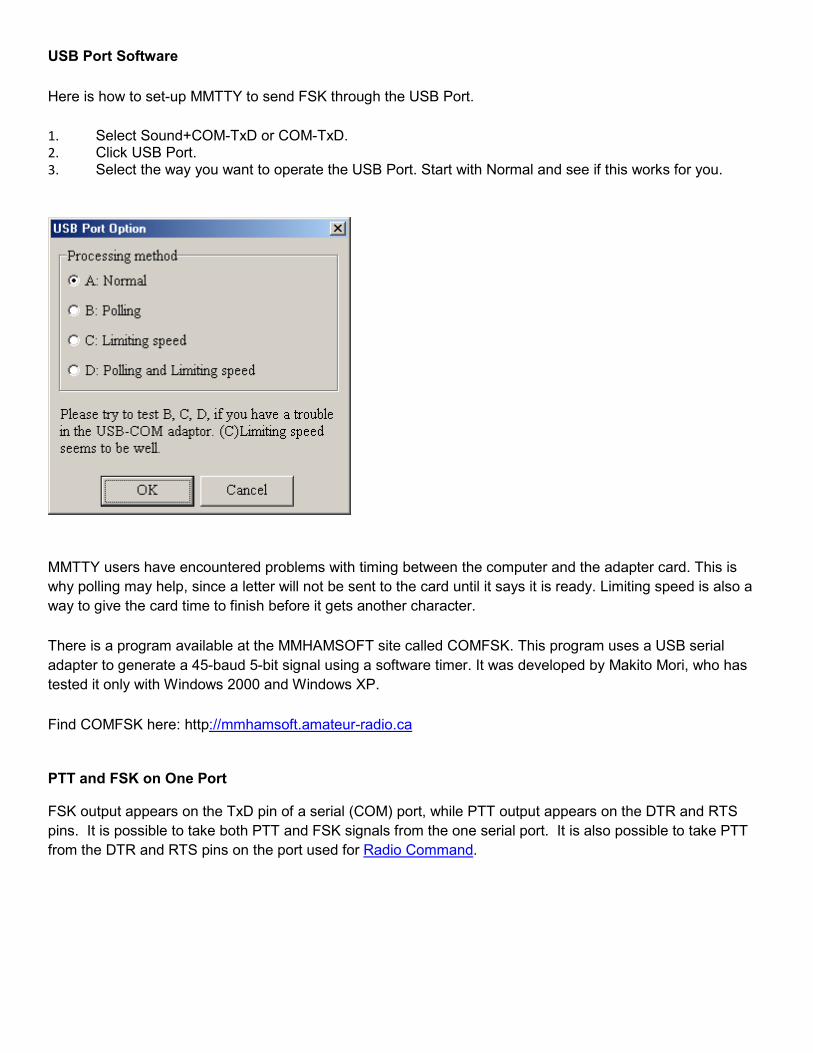
USB Port Software
Here is how to set-up MMTTY to send FSK through the USB Port.
1. Select Sound+COM-TxD or COM-TxD. 2. Click USB Port. 3. Select the way you want to operate the USB Port. Start with Normal and see if this works for you.
MMTTY users have encountered problems with timing between the computer and the adapter card. This is
why polling may help, since a letter will not be sent to the card until it says it is ready. Limiting speed is also a
way to give the card time to finish before it gets another character.
There is a program available at the MMHAMSOFT site called COMFSK. This program uses a USB serial
adapter to generate a 45-baud 5-bit signal using a software timer. It was developed by Makito Mori, who has
tested it only with Windows 2000 and Windows XP.
Find COMFSK here: http://mmhamsoft.amateur-radio.ca
PTT and FSK on One Port
FSK output appears on the TxD pin of a serial (COM) port, while PTT output appears on the DTR and RTS
pins. It is possible to take both PTT and FSK signals from the one serial port. It is also possible to take PTT
from the DTR and RTS pins on the port used for Radio Command.

Transmit FSK
NET, AFC, Rev.
MMTTY has features that function differently or not at all when you employ FSK modulation rather than AFSK.
AFC
AFC stands for automatic frequency control, and it is explained in Demodulator Controls and AFC/ATC/PLL
Tab. It tunes and tracks a received signal by varying MMTTY's receive mark frequency and/or shift change to
fit the received signal. AFC works in FSK mode, because it operates only on the received signal.
NET
With AFSK, you may decide to let the mark transmit frequency change along with the receive frequency. That
is, if MMTTY uses AFC to track a signal, NET allows you to send your next transmission with the same mark
and/or shift as the received signal. NET does not work for FSK. The FSK modulator is not under MMTTY's
control, so it always transmits a mark frequency and a shift determined by the modulator itself. Pressing NET
when using FSK does not do anything.
The Always fix shift box on the Tx tab does nothing when you use FSK.
Rev.
For AFSK, the Rev. button reverses the mark and space signals on receive and transmit. This has the same
result as changing sidebands at your transceiver.
However, with FSK, only the receive mark and space signals are under the control of MMTTY. The transmit
mark and space are determined by the FSK modulator. If you have to reverse mark and space on both transmit
and receive, the way to do this is to change sidebands at the transceiver, because the transceiver FSK port is
set up to correspond to the other sideband on receive. Some transceivers have a RTTY Reverse Mode switch
on the front panel. Once this is correct, use the same setting all the time.
The Disable Rev. box on the Tx tab does nothing when the keying is FSK; it only works for AFSK.
Test Transmission for FSK
MMTTY has a special test transmission intended for FSK. This function does not send characters to the sound
card; it only generates FSK
• Click Option | Test • MMTTY goes to transmit mode and sends a string of RY, followed by the entire BAUDOT character
......set. • Press TXOFF to terminate this string.

Receive Audio Levels
MMTTY warns when the audio level is too great for the program to handle. This usually happens on signal
peaks, possibly when you have a really strong signal. When the audio signal level is too great, MMTTY will
indicate this with the word overflow on the FFT display.
Use the Windows mixer to adjust the receive level so that the overload warning does not appear. It is probably
the Wave control that adjusts the receive audio level. If you must use the Master control, then you will have to
readjust the transmit audio level as well.
Operating Techniques
Type Ahead
Sending By Letter, Word, or Line
Sending Prepared Messages
- Macro Buttons
- Keyboard Shortcuts
- Edit Window
- Transmit Files
- Paste to Tx Window
Save Text Data
- Time Stamp
- Record Receive Data
- Record Transmit Data
- Print Data
Stay on Top
Macro Button Display
Autosend CR/LF With TX Button
Type Ahead
MMTTY has a type-ahead buffer to remember what you typed, even if you typed it before going to transmit
mode. The type-ahead text appears in black in the transmit window. If you use a macro to begin transmission
("his callsign" de "your callsign") you can still type ahead before you press the macro button. When you press
the macro button, the macro is sent first, followed by the data in the type-ahead buffer. Once the data are sent,
they turn red in the transmit window.

Backspace with the backspace key on your keyboard, to erase letters from the end, or use the arrow keys to
go to a letter and then delete it. This works only until the letter is transmitted. Once a letter is transmitted, there
is no Baudot code to erase it; it remains on the screen of the receiving station, so it remains in your transmit
window as well.
There is a RTTY convention to type two or three Xs (e.g., HILLOXXX HELLO) to tell the receiving station to
ignore a word or words that came before.
Sending by Letter, Word, or Line
A way is provided to help you transmit cleaner text. Click Option | Way to send and you see the choices
Character out, Word out, Line out.
If you want to see what it was like to use the "green keys" on an old Teletype Model 28 teletypewriter, select
Character out, and every letter is typed as soon as MMTTY gets to it.
Those used to modern computers can select Word out: MMTTY sends a word only when the following space
is typed. You can correct the spelling in the word if you realize the mistake before the following space is typed
or before MMTTY gets to the word.
Line out means that you must reach the end of a line or type a carriage return to send the characters. This
method is not recommended because it leads to slow communication. Your station diddles while you type a
line, then sends it. When you are finished typing, there is an entire line to send before your station goes to
receive mode.
Delete the last line of typed text with the Ctrl-Backspace combination, as long as it has not been transmitted.
If you are a slow typist, you may choose to slow transmission with the Transmission Delay slider at the far right
of the Transmit menu. This gives you more opportunity to correct your typing mistakes. See the Transmit Menu
topic.
Word out is the most common procedure for MMTTY users. A few mistakes in conversation do not destroy the
meaning of what you are saying, and all operators are in the same situation.
Sending Prepared Messages
A lot of communication in ham radio is standard information, such as:
• You call CQ with a standard call. • You answer a CQ with a standard identification. • At the beginning and end of each "over" you identify yourself and the other station. • At some point you may send a "brag file" with information about your station. • At the end of a QSO you may use a standard closing. • In a contest, almost everything is standardized.

The next subtopics discuss how you can partly automate these "canned" messages.
Macro Buttons
On the main display MMTTY has a total of 20 macro buttons--16 control buttons on the control panel at the top,
and four more in the transmit menu in the middle of the display. The topic Macros tells how to program these
buttons. You may also want to look at Transmit Menu.
The macro buttons offer an easy way to begin and end a transmission or QSO, and you can put a short "brag
file" in one also. The macros have special codes for your call and the other station's call (click to put his
callsign in the Call window, see Receive Window). If you begin a transmission with one of these macros, you
can make a single click to begin transmission and identify, and begin typing additional information while
MMTTY sends the standard beginning of QSO data.
Right-click on a macro button to program it. Left-click on a macro button to use it.
Transmissions should begin and end with the other ham's call and then your own call. This is already set up as
the 1x1 button in the Group 2 macros in the transmit menu.
Keyboard Shortcuts
Many hams prefer to use a keyboard shortcut to control PTT, because they are already typing on the
keyboard. The shortcut to begin transmission is F9 and the shortcut to go to receive is F8. These are
programmed by clicking Edit | Assign shortcut keys. Programming is discussed in Keyboard Shortcuts.
Edit Window
In the transmit menu is a small message window. This window contains scripts that you can use and
customize.
To use a script, press the down arrow and select the script; its text appears in the transmit window, to be
transmitted.
To edit a script, select one in the window and press the edit button next to the window. A special edit dialog
comes up. Use the Assign button to record your changes to a script. Clear this script from the transmit window
when you are done. See Macros for full programming information.
Transmit Files
MMTTY can only transmit plain text, and the text is converted to uppercase. These are restrictions of the
Baudot code. You can put small amounts of text (e.g., brag file) on any macro button, but, during your
transmission, you can click File | Send text and select a text file to transmit.
This can be useful in traffic-handling situations, where you receive a file using any computer input method, and
then you transmit it via RTTY.

Paste to Tx Window
You can open other applications that have text and use Windows copy techniques to copy text data from them.
Then you can use this MMTTY menu selection to paste the copied information directly into the Tx window for
transmission.
• Open the Windows file or application and copy the text data. • Return to MMTTY and click Edit | Paste to TxWindow. The data appear in the transmit window. • The data are transmitted when MMTTY gets to that point in the transmission.
MMTTY does not use a right-click menu for copy-and-paste.
Save Text Data
MMTTY can save any data that appear in the receive window, and it can add a time and date stamp.
Time Stamp
You can put a time stamp for each line as it appears in the receive window.
• Click File | Options of received-log | Show time stamp
• Click File | Options of received-log | Show time stamp in received window
The time stamp includes the date, and an indication of whether the data were Rx (received) or Tx (transmitted).
Record Receive Data
The general procedure is to get MMTTY to save data into its own receive buffer, and then, after what you want
is in the buffer, save those data to a file that you name.
1. Click File | Log Rx file. MMTTY saves its receive window data. 2. Click File | Rx Window to file to cause the saved data to go to a file that you name in the Explorer
window that opens up. 3. This saved file can be opened with a word or text processor.
If you are in a contest, you may want to repeat step 2 every so often to save the data in batches, in case your
computer crashes.
Record Transmit Data
All data that appear in the transmit window are sent to the receive window when they are transmitted.
Print Data
Record the data to a file, as shown above, open the file in a word or text processor, and print from there.

Stay on Top
You can make MMTTY stay on top of other programs until it is minimized with its own minimize button. Usually,
this is done when MMTTY is a window that is smaller than the full screen.
Click Option | Setup TNC emulation and check Stay on top.
Macro Button Display
The sixteen macro buttons can be displayed as a 4x4 keypad or in a single row above the receive window.
Click View | Macro buttons.
Autosend CR/LF With TX Button
If your transmission to the other ham begins on a new line, he can see the information better. If you send a
CR/LF at the beginning of your transmission, you increase the likelihood that print starts on a new line. Click
Option | Autosend CR/LF with TX button.
Macros
What Is a Macro?
What Is a Keyboard Shortcut?
Where Are Macro Buttons?
Different Types of Macro Buttons
Group 1 Macro Buttons (In the Control Panel)
Group 2 Macro Buttons (In the Transmit Menu)
Edit Window Macros
Macro Command List
What Is a Macro?
A macro is a script assigned to a key or a display "button" that does a number of things. Usually there is text
to be transmitted, but there may also be special commands that tell the program to do something. For
example, you might have a macro that uses the program's knowledge of the other station's callsign to identify
him at the beginning of your transmission. Macros can control transmit and receive, so you can have a macro
that begins transmissions with callsign identification.
When you program a button or edit macro, everything you enter is either a software command or text to be
transmitted.
What Is a Keyboard Shortcut?
A keyboard shortcut is a way to perform an operation, possibly call a menu item, but most often invoke a
macro from the keyboard without using the mouse.

Where Are Macro Buttons?
There are two groups of macro buttons, Group 1: sixteen macro buttons in the control panel; and Group 2: four
macro buttons in the transmit menu above the transmit window. In addition, there are nine Edit messages
accessible through the Edit window in the transmit menu.
Different Types of Macro Buttons
The three types of macro procedures mentioned in the above paragraph (Group 1, Group 2, Edit messages)
differ in three ways:
1. Whether you can use them directly from the keyboard (keyboard shortcut). 2. How the backslash (\) and number sign (#) commands work in the macro. 3. How the macro works when you begin with text.
The macros were designed for certain functions, but they are so versatile that you may choose to use them
differently.
Group 1 Macro Buttons (In the Control Panel)
Group 1 Macro Buttons are the 16 macro buttons in the control panel. They are intended for contest or
DXpedition operation, but you can use them for anything.
Here are the Group 1 Macro Button commands:
• Backslash(\) at the beginning of a Group 1 macro copies the content of the macro to the transmit ......window and begins transmitting.
• Backslash (\) at the end of a Group 1 macro turns off transmitting and returns to receive. • Number sign (# or uppercase 3) at the beginning of a Group 1 macro copies the contents of the
......macro to the transmit window but does not begin transmission. • Number sign (# or uppercase 3) at the end of a Group 1 macro repeats the macro. The contents
......of the macro repeat until you press TX or TXOFF. • If you do not use any command at the beginning of a Group 1 macro, but simply begin with text, the
......macro begins to transmit immediately and sends the text, but the text does not appear in the
......transmit window.
Group 1 macros are labeled M1 through M16. Some of these are already programmed, but all of them can be
changed (see Editing Macros, below).

By default, the following shortcut keys operate these macro buttons:
Macro Shortcut Macro Shortcut Macro Shortcut Macro Shortcut
M1 Ctrl-1 M5 Ctrl-5 M9 Ctrl-9 M13 none
M2 Ctrl-2 M6 Ctrl-6 M10 F10 M14 none
M3 Ctrl-3 M7 Ctrl-7 M11 F11 M15 F7
M4 Ctrl-4 M8 Ctrl-8 M12 f12 M16 F8
Group 2 Macro Buttons (In the Transmit Menu)
The four Group 2 macro buttons were put in the transmit menu because they are intended for frequent
operation during most QSOs.
Here are the Group 2 Macro Button commands:
• Backslash (\) at the beginning of a Group 2 macro clears the transmit window. • Backslash (\) at the end of a Group 2 macro stops transmission and switches to receive. • Number sign (# or uppercase 3) at the beginning of a Group 2 macro begins transmission. • A Group 2 macro that begins with text puts the text in the transmit window, but does not begin to
......transmit. • All text that appears in a Group 2 macro first goes to the transmit window before it is transmitted.
By default, the four macro buttons in the transmit menu use the shortcuts F2, F3, F4, and F5.
Edit Window Macros (Edit Window Messages
There are macros in a dropdown list in the transmit menu. Press the down-arrow to the right of the window to
see them. Select the macro you want and the text appears in the transmit window, ready for transmission.
Commands for these window macros work the same as Group 2 macros.
• Backslash (\) at the beginning of a window macro clears the transmit window. • Backslash (\) at the end of a window macro stops transmission and switches to receive. • Number sign (#) at the beginning of a window macro begins transmission. • Beginning with text puts the text in the transmit window, but does not begin to transmit. • All text that appears in a window macro goes to the transmit window before transmission.
Window macros do not have default shortcuts.

To edit these Edit Macros:
• Select one to bring it into the window. • Click the Edit button next to the window. • Press the Assign button at the lower right of the editing window to record the change. • Press Close.
You can use the Clear key in the transmit menu to clear the text from the transmit window when you are done.
There is a table of the macro commands in the next topic, Macro Command List. The keyboard shortcuts are in
a table in the following topic, Keyboard Shortcuts.
Macro Command List
Macro Command List
\ For Group 1 macros, \ at the beginning copies the message to the transmit window and puts
MMTTY into transmit mode. If you do not use the \, Group 1 macros put MMTTY into transmit and
are transmitted without appearing in the transmit window.
\ For Group 2 macros and window macros, \ at the beginning clears the transmit window.
\ For Group 2 macros and window macros, \ at the end of the macro switches to receive.
# For Group 1 macros, # at the beginning copies the message to the transmit window, but MMTTY
does not go into transmit mode automatically.
# For Group 1 macros, # at the end of the macro repeats the macro.
# For Group 2 macros and window macros, # at the beginning puts MMTTY into transmit mode and
begins transmitting the macro. If you do not use the #, you must put MMTTY into transmit mode with
the TX button.
%c The other operator's call sign from the Call window.
%f GM/GA/GE
%g Greetings – HELLO/GOOD MORNING/GOOD AFTERNOON/GOOD EVENING
%m My call sign.
%n The other operator's name from the Name window.
%q The other operator's QTH.

%r The other station's RST from the RST window (it may include a contest number).
%s My RST.
%t UTC time in 1234 format.
%D Current UTC date (e.g., 2000-SEP-05).
%E End of definition.
%F Force transmit FIG code
%L Force transmit LTR code
%M The contest number portion in My RST.
%N The contest number part (after RST) of his/her RST from the RST window.
%R The RST part of his/her RST from the RST window.
%T Current UTC time (e.g., 17:44).
^ Wait for 1 second.
~ Stop transmitting mark (stop carrier).
[ Disable diddle.
] Enable diddle.
Keyboard Shortcuts
Keyboard shortcuts are keyboard key combinations that perform functions in MMTTY. These functions can
also be performed with display buttons, menus, and selections, but sometimes it is easier to operate from the
keyboard.
Click Edit | Assign ShortCut keys to see and edit the keyboard shortcuts. There are three columns: Internal,
Define Name, and Key. The "Internal" column shows the name of the operation, "Define name" describes what
happens, and "Key" specifies the keyboard key to press.

At the bottom, "Del" deletes the assignment marked by the cursor and Check Dupe checks to see if the key
you have typed in for a new assignment is already assigned. At the lower left is a drop-down list of all the
keyboard keys that can be assigned. You must use this list to select the key to use in a new assignment.
1. Go to the Key you want to program as a shortcut and highlight the Internal term. 2. If there is a current key assignment, press Del to remove it. 3. Review the Assign Shortcut list to find a keyboard key that is not assigned. 4. Use the drop-down menu at the lower left to select the key you want to assign and highlight that
key. 5. If you select a key that already has another assignment, the new key name appears in red. If you
select a key that can be assigned, the new key appears in black. A key that is assigned to two operations does not work.
6. To find the original assignment of a key, press Check Dupe and MMTTY jumps to the other assignment. Delete this other assignment and the new assignment works.
7. When all is OK, press Close.

Contest Operation and Logging
Contest Mode
Running Mode and S & P Mode
Contest Mode
Contest mode speeds both QSO completion and logging. Three important features of contest mode are:
• A single click sends certain macros in sequence. • The QSO is logged in MMTTY log. • Additional details are up to the operator.
Contest Mode uses macros that are planned and coded by the operator. The operator should plan macros for
regular operation, plus special macro sequences to use in special situations, such as when the other station
does not copy your report or callsign, or when you do not copy his report or callsign.
Contest mode uses automatic callsign and RST logging, plus the QSO button on the logging menu. Here is
the general approach (see Running Mode and S&P Mode below):
• Click the other station's callsign during the QSO. • If necessary, click the other station's RST during the QSO. • When it is your turn to transmit, click the QSO button the first time; MMTTY starts to log this QSO
and sends a first macro automatically. • Click the QSO button the second time; MMTTY records the QSO to the log permanently and sends
a second macro automatically.
Running Mode and S
Contest mode uses two modes of operation, Running Mode and Search and Pounce (S&P) Mode. The
sequence of automatic operation is different for each of these modes.
• Running Mode means staying on one frequency and calling CQ or QRZ to get stations to work you ......on that frequency.
• S&P Mode means finding other stations that are calling CQ, calling, and working them.
The word Call on the logging menu will turn red in Running Mode. To go in and out of Running Mode, do one
of two things:
• Click the word Call on the logging menu, or • Click Option | Running Mode

The other topics under Contest Operation show how to set-up and use these modes. These topics are:
• Logging
• Prepare for Contest Mode
• Input Tab
• QSO Button Tab
• Conversion Tab
• Misc Tab
• Operate a Contest • After the Contest
Note: Here is a special warning to every MMTTY user who uses Contest Mode. After the contest, turn off
Contest Mode. Click Option | Setup Logging, Input tab, Check Off at the far left, in the Contest area. If MMTTY
sends a serial number all the time, you forgot to turn off Contest Mode.
Logging
Select a Log
Enter Data
- Sequential Clicks
- Select a Window and Click
- Name Window = QTH Window
- Keyboard Shortcuts
Record Data
Clear Log
Review and Edit Log Data
--Current QSO Data
--Log Data for All QSOs
--Remove or Edit a Logbook Entry
--Search the Log
--Export the Log
--Import a Log
--Make an Index
Logging Menu Topic Under Basic Operation
MMTTY Log is always running. It occupies the Logging Menu just above the receive window.
Select a Log
You can have more than one log: each log has a name and the extension ".mdt." If you want to select a
different log to use, Click File | Open LogData File and select the log file that you want. To create a new log,
type in a new name in the Explorer window that opens up. You are told that the file does not exist, and asked if
you want to create a new one. Click "Yes" and the new log is created. We suggest that your main log use your
call letters.

Enter Data
Some entries can be made with a mouse-click. When you do the operation, the data fill the appropriate data
window in the logging menu.
Sequential Clicks
Point to data in the receive window and left-click the mouse:
• the first click enters the data under the cursor into the Call window, • the second click enters the data into the Name window.
Select a Window and Click
When there is a callsign in the call window, you can click on the Call, Name, or MY(RST) window, then point
and click on data, and the data enter that window. MMTTY does some checking before entering data:
• You cannot click on your own callsign and enter it into the Callsign window. • You cannot click on a number to enter it into the Name window. • You can only click and enter numbers from 111 to 599 into the MY(RST) window.
These restrictions do not hold when you type into a window. You can enter My(RST) as Bob, and record the
other station's name as 589, but you must type these entries.
Name Window = QTH Window
The name window also serves as the QTH window. Click on the word Name and it changes to QTH. The
window title that shows is the place where the data are stored.
Keyboard Shortcuts
There are keyboard shortcuts for data entry. Click on an entry in the receive window, then type the shortcut to
enter data into the window. Here are the shortcuts and the data windows they fill:
• Callsign is Ctrl-C. • My(RST) is Ctrl-R. • Name is Ctrl-N. • QTH is Ctrl-M.
Record Data
Once you have data in the Call field, the QSO button turns black. Push the QSO button to mark the start time
of the QSO. The button stays pressed, showing that you are entering data for this QSO.
The last window on the right is the band. You may enter this value by hand, but it stays the same from QSO to
QSO until you change it. This value can be read directly from your transceiver if you are connected to the
transceiver via a serial port. You must follow the instructions for Radio Command, and select VFO Polling. See
the topic Radio Command.

Here is a picture of the log windows filled out, ready for you to press the QSO button a second time to end the
QSO and record the data.
When the QSO is over, click on the depressed QSO button one more time, and the data enter the logbook, the
windows clear, and the QSO button
You can also save the log data with the command File | Save Data now.
Clear Log
You may enter data but then fail to make the QSO. If this happens, click the Init. button to the left of the Call
window to clear the current QSO data.
Review and Edit Log Data
Current QSO Data
To review and edit all the data for the current QSO, click the Data button to the left of the Call window (or click
View | Current QSO data) to see a full log data entry page. There are a number of additional fields available,
including mode and QSL sent and received fields.
At the bottom of the log data page for this QSO is a button labelled Receive Window. Click Receive Window
to see the last 512 lines in the receive window.

Here is a picture of the log data entry page.
QSL S and R
There are two windows relating to QSL sent (S) and received (R). These have built-in codes on a drop-down
list. These codes are from MMLOG, a freeware logging program from JE3HHT. This logging program is only in
Japanese. You can use these codes, or you can type any keyboard letter or character instead of using the
drop-down lists. If you use MMLOG, consult that program for the meaning of the codes. Otherwise, you may
use them as you want. Some of these codes have the following meaning in MMLOG: N = No QSL; p =
pending; D = sent direct; S = sent SASE/SAE.
Log Data for All QSOs
To review and edit the entire log and its contents, Click View | LogData List. MMTTY brings up the log file. To
edit another log, click File | Open LogData File, and MMTTY asks you to select a log file.

Here is a picture of a Log Data File:
There are a number of actions you can take while reviewing this file.
• Scroll up and down to look at entries. • Scroll side to side to see all the data for each entry. • Regenerate the index for the file. • Search the file. • Save a selected range of this file as another log file. • Import and export data to and from this file. • Edit entries in the file (change, delete).
For the following log operations, you must have the log data file open, as shown above.
Remove or Edit a Logbook Entry
To remove an entry, click anywhere on the entry and then click Edit, Cut, and the entry is deleted. Be careful,
only one field is highlighted, but Delete removes the entire line, and the line cannot be restored.
To edit any field, double-click anywhere on the entry and you get the full window to edit all fields, as if this
were the current QSO.
Search the Log
You can only search for a callsign or partial callsign. Select Find, and choose the direction that you want to
search. A window appears, into which you can enter a callsign or partial callsign. Click OK to search. While the
log is showing, there are some special shortcuts. Ctrl-F brings up the search forward box, F3 repeats the
search forward from the first hit.

Export the Log
Use the mouse cursor to select a subset of the log, then click File | Export selected range to save the outlined
entries in text, ADIF, Log200, TurboHAMLOG formats, or Cabrillo formats. The ADIF format is widely used to
exchange data among contest and log programs.
Log200 is a logging program by JH3GBD and TurboHAMLOG is written by JG1MOU. They run only on the
Japanese Language Operating System, so they not important to most English-speaking hams.
Cabrillo format is used by many contests, especially ARRL.
You can change the format of some of the data in the log before you export it in text format.
Import a Log
You can import a log to MMTTY in text, ADIF, Log200, or TurboHAMLOG formats. Click File | Import and
select the format you want. To determine the structure needed for the text format, export some data in this
format and review the result. The text formats supported are comma-separated text (CSV), tab-separated text,
and nonseparated text. When you do the import you are asked to select the type.
Here is a picture of the screen that appears. You have a number of options you can implement from this
screen.

The screen displays the data for the first record that it sees. Each record is a number of fields, and each record
corresponds to one log entry. Each field is on a separate line. Scroll down to see and work with each field
separately.
At the bottom is a window labeled "delimiter type." You must specify the field delimiter used by the original text
or csv file. When you check one of these, MMTTY will do a quick operation on the first record and show you
the results of applying that delimiter. In most cases, only the correct delimiter will define fields; all the others
will result in no fields or only one field being defined. The delimiter is the character that separates fields.
To the right of delimiter type is a check box for UTC. If your data do not use UTC times, MMTTY assumes that
they are JST. You are strongly urged to keep your logs in UTC if you do not live in Japan.
To the right of the UTC check box is a field called Ref., with two buttons, < and >. If you press one of these,
MMTTY will go to the next record or the prior record, so you can check on what happens with several records
in the to-be-imported database.
Below the delimiter type window is a window labeled "Conv," which shows what value in MMTTY's log these
data are assigned. You can reassign data here. For example, if MMTTY makes a mistake and says that the
QTH data should be called Name, you can reassign this field to be QTH by clicking on the field to be
reassigned, at the top, and then going to this window and making a change in the Conv. assignment.
The up and down buttons also change the assignments of fields, like the Conv. window. They move the
assignment in the highlighted field up or down one field. It may be simpler to use the Conv. window., rather
than the buttons.
You can highlight some data on each field and use the delete key to delete that field from the import. When
MMTTY comes to this field in each record, it does not import the data.
The Max column sets the length of each field. This value does not matter if you are using a delimited text file,
where there is a separator between fields, such as a comma, but it matters if the file delimiter is None. Set Max
at the bottom of the display. The default type of export is comma-delimited, which is the most common type of
simple (flat) exported file. A CSV file is a file of "comma separated values."
If you have nonseparated text (the file delimiter is None), set the length of each field to what you expect it to
be. For example, if you set aside ten characters for callsigns, then you must set the length of the callsign field
to ten. The Init Max. button sets this value to zero. It is probably best not to use this button, but to make the
entry separately for each field, if you are using nondelimited data.
Make an Index
This is an emergency procedure. If the callsign index becomes corrupted, and you fail to find a callsign that is
there, or MMTTY goes to the wrong record, click File | Make Index to recreate the index file.
Prepare for Contest Mode
Prepare a New Log File for the Contest
This topic and the next two show the steps to set up for a contest using MMTTY's contest features. The final
topic under Contesting, Operating a Contest, shows how to put these preparations to use in a RTTY contest.
Prepare a New Log File for the Contest
1. Click File | Open Log Data File to open a Windows Explorer window. 2. Navigate to the computer location where you want to store the contest log. 3. Name the contest file and click Open on the Explorer window to start this file.
Input Tab
Specify Automatic Defaults (Input Tab)
Step 2: Specify Automatic Data Defaults (Input Tab)
In this step, you decide which data are to be determined automatically, and which data are to be entered by the
operator, along with some other parameters. You can change data during or after the QSO.
• Click Option | Setup Logging | Input tab. • Click the box labeled Contest mode at the upper left. Remember to turn off Contest Mode at the
......end of the contest. • Specify a format for the HisRST exchange at the lower left. When you specify HisRST, 599+001
......puts a serial number in the exchange. Remember to reset HisRST to 599+? after the contest. • At the block entitled Copy Band or Freq, check Band to put only the band data in the log. • Specify UTC time zone. • Save all data as uppercase if you want. • MyRST 599 puts 599 in the My(RST) field of the logging menu. • Copy Before Data is explained below. • There are boxes to select CQ/RJ, DX Expedition, and BARTG. These boxes bring up default
......settings for these contests.
HisRST Plus Other Data (599+?)
The selection for HisRST is shown as "599+?" This allows you to put more text into the His(RST) window of
the logging menu, and that text will stay there to be added to every QSO. It is transmitted along with the 599,
and it stays in the His(RST) window. In other words, when you put "599 Jan" in the HisRST window, each time
His(RST) is transmitted, it comes out as 599 Jan. If a contest calls for you to transmit your name, state, county,
zone or other fixed data, this is how to do it.

Copy Before Data
Copy Before Data means that you can bring in data from previous QSOs with the station whose call is in the
Call window. For example, if you must record the other operator's name in a contest you can do this:
• Work him on one band and put his name in the Name window of the logging menu. • His name is entered automatically into the name window the next time you enter his callsign into the
......Call window.

QSO Button Tab
Programming the QSO Button
Specify How the QSO Button Works in Running Mode
Specify How the QSO Button Works in S&P Mode
Step 3: Programming the QSO Button (QSO Button Tab)
To program the QSO button, click Click Option | Setup Logging | QSO Button tab.
Check Auto Macro to enable the rest of the selections on this page. When the contest is over, instead of
unchecking each box, you can leave things set for the next contest and just uncheck Auto Macro.
The next section tells how to set the QSO button to operate in each of the two modes: Running mode and S&P
mode. Switch between these modes on the main screen by clicking on the word Call in the logging menu. The
next two sections cover each of these modes.
Step 4: Specify How the QSO Button Works in Running Mode
On the QSO Button tab, at the left there is a section labeled Running. Press the set button next to the label 1st,
and you can program the actions for the first press of the QSO button in Running mode. All the macro
commands work here. When you are done, program the actions for the second press of the QSO button. If you
only want the QSO button to do one thing, you can turn off the programming for either first or second press.

The first press of the QSO button automatically sends MMTTY into transmit mode before beginning the macro.
The QSO button macros operate like Group 2 macros: they automatically put MMTTY into transmit, but require
the \ to return to receive.
The 1st press is programmed as follows, by default:
%c %c UR %R -%N -%N BK
\
To understand the code, refer to the Macros and Shortcuts topic.
• %c means send the other station's call. • UR is text. • %R is the RST part of the other station's report. • %N is the serial number of the other station's report. You must have already specified 599001 as
......HisRST on the Input tab. • BK is text, and when the macro ends, MMTTY goes back to receive mode. This is your first
......transmission for each station in running mode. • \ is the code to go to receive mode.
The 2nd press is programmed as follows, by default:
QSL TU QRZ? DE %m %m K
\
This sends QSL TU QRZ? DE "yourcall" "yourcall" K.
The second press of the QSO button also puts the QSO in the log and clears the log window.
There is a third entry under Running, called Dupe, which operates on the second press of the QSO button if
the callsign is recognized as a duplicate on this band.
The dupe response to the second press is programmed as follows, by default :
%c SRI QSO B4 QRZ? DE %m %m K
\
You can leave Dupe unchecked if you do not want to have MMTTY dupe-check during the contest, or you can
program this function differently.

Step 5: Specify How the QSO Button Works in S&P Mode
When you switch to S&P mode the S&P macros operate. There is a macro for the first and second press of the
QSO button, but no dupe response, since you are the one initiating the contact in S&P mode.
The default S&P QSO button macro scripts provided with MMTTY are:
Press 1:
DE %m %m K
\
This sends: DE "yourcall" "yourcall" K
and then MMTTY goes to receive mode.
Press 2:
%c %R-%N-%N TU
\
This sends: "hiscall" "RST report" "serial number" "serial number" K
and then goes to receive mode.
Conversion Tab

Some of the items on the Conversion tab are needed only for Turbo HAMlog, a Japanese logging program.
For other use, keep the following default values:
Time zone: auto (UTC is already specified for logging on the Input tab)
ADIF Adjust RST:checked
Link application:off
Misc Tab
You can tell MMTTY to ignore the daylight savings time change, and change date format in the log in the Misc
tab.
Click the Autosave box to automatically save the log file to disk. You can also save the log file manually by
clicking File | Save data now. If this choice is gray, then no new data have been entered since the last save.
The time offset is usually not needed. MMTTY reads your computer clock, and determines the time and the
time zone. It then translates this into UTC and records log entries as UTC. If there is a problem and you see
the wrong time recorded, make adjustments here.
Operate a Contest

Start Contest Mode
- Record Receive Window to File
Running Mode
- Enter Running Mode
- Call CQ
- Answer a Response to Your CQ
- Complete the Contest Exchange
S & P Mode
- Call the Other Station
- Complete the Contest Exchange
Duplicate Contacts (Dupes)
Clear Logging Menu Data
This topic covers how to use MMTTY's contest operation features during the contest.
Start Contest Mode
First, prepare MMTTY as discussed the previous topics under Contest Operation. A good start would be to
prepare a new log with a name specific to the contest, as discussed in the topic, Prepare MMTTY.
Second, follow the other topics to prepare MMTTY for the contest you want to operate. Most of the preparation
deals with planning and coding the macros for first and second press of the QSO button.
Third, turn on Contest Operation by clicking Option | Setup Logging | Input tab and checking Contest On.
At this point, it may be wise to exit MMTTY and restart it. This records the setup data on disk, so if you have a
computer crash, when you restart you will still be in contest mode.
Record Receive Window to File
Many contesters with big hard drives also enable recording of the Rx window data. This records all the data
that pass through the Rx window during the contest, and allows you to review exchanges and make
corrections, such as if you accidentally confuse serial numbers or record incorrect received data. Click File | Rx
Window to File to begin recording.
The rest of this topic discusses how to use MMTTY in the contest.
Running Mode
Running mode is used when you stay on one frequency, call CQ, and respond to stations that answer you.
The QSO button only functions when there is a callsign in the Call window, so you should program a CQ call
using one of the Macro keypad keys. The CQ1 and CQ2 keys provide a good starting point for a contest CQ.

Enter Running Mode
Enter Running mode one of two ways:
1. Click Option | Running Mode. If you are already in Running mode, there is a check next to it, and the word "Call" on the logging menu is red.
2. Click the word "Call" on the logging menu; it turns red and you are in running mode.
If the word "Call" does not turn red, then you did not turn on Contest mode, mentioned above.
Call CQ
Press the programmed CQ key to send CQ.
(a name="answeraresponsetoyourcq">Answer a Response to Your CQ
When someone answers your CQ and identifies, left-click on his callsign to automatically put it in the callsign
window, or type it into the window. The QSO button turns from gray to black. If you have already prepared
MMTTY to give a planned RST, then there already is a 599 in the My (RST) window.
Press the QSO button to complete the first macro. Normally, this macro identifies the other station, sends the
full contest exchange, and identifies your station. The QSO button itself sends MMTTY into transmit mode
when the macro starts, and returns to receive mode when the macro is complete.
Complete the Contest Exchange
When the other station sends his contest exchange, make any changes or additions to the My (RST) window,
such as entering the serial number or UTC he sends to you, and press the QSO button a second time. This
records the QSO and sends another CQ or QRZ.
S & P Mode
To work in S&P mode, it is useful to have a macro button to call other stations. The 1x2, 2x3, and DE3 macros
that come with MMTTY are a good starting point.
To enter S&P mode, click the word Call in the logging window so it turns black.

Call the Other Station
Left-click the CQing station's callsign to put it in the Call window. Press the QSO button to call the other
station.
If the other station does not answer, you can do one of two things:
1. Press Init to clear all data, click his call again, and then press QSO to call him again. Or, 2. Use the Macro keypad button you programmed to call him again, leaving the QSO button alone and
......leaving all data in the log menu.
Complete the Contest Exchange
When you receive a response, click the QSO button a second time to send your response and put the data in
the log. If there are data to enter in your log, you can do this before you press QSO a second time, or you can
press the Data button to view and edit the QSOs you have had with this station.
Duplicate Contacts (Dupes)
MMTTY checks for duplicate contacts (stations contacted before) in contest mode.
To check only for contacts on the same band (the way most contests operate), click Option | Setup Logging |
QSO Button tab, and check the box labeled Check Same Band. Now, if you work the same station on a new
band, it will not count as a dupe.
When you enter a duplicate call into the Call window, whether you type it or click it in, it will appear in red if it is
a dupe. The operator must watch for a callsign printed in red, because MMTTY will make the duplicate contact
if you press the QSO button and complete the QSO.
Clear Logging Menu Data
It may happen that you try to call a station several times, using the QSO button and then one of the macro
buttons, but you are not successful in making the contact. Press the Init button on the Logging menu to clear
all the data. This will also leave the serial number as it was, so it is used for the next good QSO.

After the Contest End the Contest
- Clear RST
Clean Up
Save Your Log
- Generate a Cabrillo File
- Cabrillo Examples
End the Contest
When the contest ends, turn off contest mode by clicking Option | Setup logging | Input tab and click Contest
OFF. Later on, if MMTTY begins to do things that are unexpected, like sending a serial number with every
report, the first thing you should do is check to see if Contest Mode was turned off and that HisRST is now
599+?, and not a serial number.
Also, make sure that you have cleared out any extra data (e.g., Name or QTH) from the HisRST window on the
logging menu.
Clear RST
When the contest is over and you follow the above directions, MMTTY will continue to automatically enter
serial numbers in the His(RST) window. To clear this situation you have several choices.
1. Start a new log. The practical way to do this is to begin a new log for each contest, and then start or ......return to a non-contest log after the contest.
2. Use the drop-down feature in the His(RST) window to select 599, log a QSO that way, then repeat ......this step. After the second time, the His(RST) window should show 599. You can use dummy QSOs ......and then delete them from the MMTTY log.
3. Go to the last QSO in the log and change the His(RST) entry to 599.
In general, when MMTTY starts, the format of His(RST) is the same as the last QSO in the log.
Clean Up
When the contest is over, there are a few things you should do.
• Turn off contest mode. Click Option | Setup logging, look in the Contest block and click Contest ......OFF.
• Just below that, in the HisRST block, click 599+? to stop sending serial numbers. This should be ......automatic when you turn Contest OFF, but check.
• Remove any extra information (e.g., name, QTH) that is in the HisRST window in the logging menu.
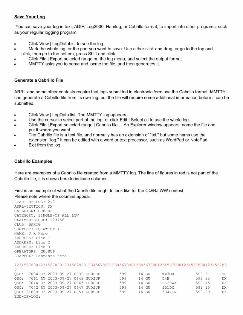
Save Your Log
You can save your log in text, ADIF, Log2000, Hamlog, or Cabrillo format, to import into other programs, such
as your regular logging program.
• Click View | LogDataList to see the log. • Mark the whole log, or the part you want to save. Use either click and drag, or go to the top and
click, then go to the bottom, press Shift and click. • Click File | Export selected range on the log menu, and select the output format. • MMTTY asks you to name and locate the file, and then generates it.
Generate a Cabrillo File
ARRL and some other contests require that logs submitted in electronic form use the Cabrillo format. MMTTY
can generate a Cabrillo file from its own log, but the file will require some additional information before it can be
submitted.
• Click View | LogData list. The MMTTY log appears. • Use the cursor to select part of the log, or click Edit | Select all to use the whole log. • Click File | Export selected range | Cabrillo file.... An Explorer window appears; name the file and
......put it where you want. • The Cabrillo file is a text file, and normally has an extension of "txt," but some hams use the
......extension "log." It can be edited with a word or text processor, such as WordPad or NotePad. • Exit from the log.
Cabrillo Examples
Here are examples of a Cabrillo file created from a MMTTY log. The line of figures in red is not part of the
Cabrillo file, it is shown here to indicate columns.
First is an example of what the Cabrillo file ought to look like for the CQ/RJ WW contest.
Please note where the columns appear. START-OF-LOG: 2.0
ARRL-SECTION: DX
CALLSIGN: GU0SUP
CATEGORY: SINGLE-OP ALL LOW
CLAIMED-SCORE: 123456
CLUB: BARTG
CONTEST: CQ-WW-RTTY
NAME: U R Name
ADDRESS: Line 1
ADDRESS: Line 2
ADDRESS: Line 3
OPERATORS: GU0SUP
SOAPBOX: Comments here
12345678901234567890123456789012345678901234567890123456789012345678901234567890123456789
0
QSO: 7034 RY 2003-09-27 0639 GU0SUP 599 14 GU WW7OR 599 3 OR
QSO: 7061 RY 2003-09-27 0643 GU0SUP 599 14 GU D4B 599 35 DX
QSO: 7044 RY 2003-09-27 0645 GU0SUP 599 14 GU RK2FWA 599 15 DX
QSO: 7042 RY 2003-09-27 0647 GU0SUP 599 14 GU S51DX 599 15 DX
QSO: 21089 RY 2003-09-27 0651 GU0SUP 599 14 GU 5B4AGN 599 20 DX
END-OF-LOG:


Below is an example of what the Cabrillo output looks like for the BARTG Spring contest. START-OF-LOG: 2.0
ARRL-SECTION:
CONTEST: <== e.g. ARRL-RTTY, CQ-WW-RTTY, CQ-WPX-RTTY, BARTG-SPRINT, BARTG-RTTY
CALLSIGN: GU0SUP
CATEGORY: <== e.g. SINGLE-OP ALL HIGH, SINGLE-OP-ASSISTED 20M LOW
CLAIMED-SCORE: 123456
OPERATORS:
CLUB:
NAME: <== your name
ADDRESS: <== your postal address
SOAPBOX:
CREATED-BY: MMTTY Ver1.65
12345678901234567890123456789012345678901234567890123456789012345678901234567890123456789
0
QSO: 3500 RY 2004-02-12 1729 GU0SUP 599 001-1729 G3ABC 599 001-1729
QSO: 3500 RY 2004-02-12 1729 GU0SUP 599 002-1729 G3XTT 599 003-1729
QSO: 3500 RY 2004-02-12 1730 GU0SUP 599 003-1730 F6IRF 599 012-1730
END-OF-LOG:
And here is the general format: START-OF-LOG: 2.0
ARRL-SECTION: DX
CONTEST: BARTG-RTTY
CALLSIGN: GU0SUP
CATEGORY: SINGLE-OP ALL LOW RTTY
CLAIMED-SCORE: 123456
OPERATORS:
CLUB:
NAME: U R Name
ADDRESS: Line 1
ADDRESS: Line 2
ADDRESS: Line 3
OPERATORS: GU0SUP
SOAPBOX: Comments here
12345678901234567890123456789012345678901234567890123456789012345678901234567890123456789
0
QSO: 21096 RY 2003-03-15 0917 GU0SUP 599 1 0917 UT2UZ 599 076 0917
QSO: 21093 RY 2003-03-15 0918 GU0SUP 599 2 0918 RW9C 599 068 0918
QSO: 21081 RY 2003-03-15 0920 GU0SUP 599 3 0920 EU1MM 599 233 0920
QSO: 21084 RY 2003-03-15 0922 GU0SUP 599 4 0922 UA4HJ 599 115 0922
END-OF-LOG:
Fill in the proper data at the top of the log (ARRL section, contest, callsign, category club, name, address, operators, soapbox) and you are finished.

Calibrate the Sound Card
Calibrate the Sound Card With a Time-Standard Broadcast Station
Calibrate the Sound Card with a Frequency Meter
Tx Offset
There is a clock on the sound card, as well as one in the computer. Some sound card clocks are not accurate.
MMTTY can adjust its frequencies and timing to compensate for the amount that the sound card is incorrect.
The following procedure does not adjust the sound card; it only discovers the card's real clock frequency.
When you put that number in the window, MMTTY changes itself to operate properly with the real clock
frequency.
When you make this adjustment, you must exit MMTTY and restart MMTTY (not the computer) to see the
change.
There are two ways to calibrate the sound card. The easiest method is to use an audio frequency meter.
However, if you do not have one of these instruments, there is a method that uses the 1-second tics sent by
time standard broadcast stations such as WWV or CHU.
Calibrate the Sound Card With a Time-Standard Broadcast Station
MMTTY has a special display that allows you to find the true clock frequency of the sound card using an
accurate 1 second tick. With this method, you do not need any instruments except for a receiver. Here are
some stations around the world that broadcast ticks each second.
Station Frequency (kHz.
WWV/WWVH 2500.0
5000.0
10,000.0
GBR 60.0 (SSB)
RWM 4996.0
9996.0
14,996.0
? 77.5

CHU 3330.0
7335.0
14,670.0
Here is the step-by-step procedure to calibrate with a time-standard station:
1. Click Option | Setup | Misc. tab. 2. Click the Adj. button at the lower left of this tab to bring up the calibration display. 3. Tune your radio to WWV or another 1-second tick standard. Set the radio frequency display to the
......carrier frequency. 4. Wait for about three minutes. If you are using 11025 Hz. calibration, you should see two lines of
......marks (vertical or slanted), corresponding to the 1-second tick sound bursts transmitted by the time-
......standard broadcast station. You will see only one line with 8000 Hz. or 6000 Hz. 5. Right-click to move the vertical green line to the tick line. This allows you to compare the tick line to
......vertical. 6. Left-click a low tick burst mark (bottom one if possible), and move the cursor to the top of the line.
......You will see a yellow line on the display. 7. Overlay the yellow line with the tick mark line, and left-click a high burst mark (top one if possible).
......This will automatically put the correct clock frequency in the adjust window. 8. Click OK to leave this display and return to the Misc tab. 9. The clock frequency determined automatically by drawing this line will be displayed in the clock
......window on the Misc tab. 10. Click OK to leave the setup display and memorize the new value. 11. Restart MMTTY for the new clock value to take effect. 12. Repeat this calibration and you should see an almost vertical line of tick marks, now that the correct
......adjustment is entered into MMTTY. You should not need to make changes this second time.

Here is a picture of the calibration display screen, showing a sound card that is pretty close to the correct
frequency of 11025 Hz., using WWV as the time standard.
Here are pictures of some calibrations performed in Europe, using MMTTY and different time standard
stations.
This is GBR, in Great Britain. The time ticks are wide, but you can pick any consistent spot on the time tick and
use it as the focal point for clicking. The arrows show possibilities for the first and second clicks.

Here are two pictures of Russian time standard station RWM. The first shows a properly adjusted display. The
second illustrates an error of 1000 ppm. Note the slanted lines. This slant will occur with any time standard if
you have an error of 1000 ppm.
Hints:
• The green and yellow lines are provided by MMTTY as a vertical reference to compare to the tick ......line.
• If the tick line is wide, reduce the sensitivity with the control at the bottom. If it is still wide, make ......sure to click at the same relative place on both top and bottom ticks (e.g., left edge).
• If the display is quite slanted at first, repeat the calibration two or three times. The last time should ......make only a small change.
• If the time standard station broadcasts a strong tone along with the ticks, and you have trouble ......seeing the tick line, it is possible to use manual notch to get rid of the steady tone. The automatic ......notch is probably too slow to remove the ticks.
• Right-click to move the vertical calibration reference line without beginning the procedure. This lets ......you look at the tick line in comparison with the vertical standard.
Note: European time standard station pictures courtesy of G3NPA.

Calibrate the Sound Card With a Frequency Meter
Here is the procedure for calibrating the computer sound card using an audio frequency meter:
• Set the frequency meter to measure the audio frequency of the audio output from the sound card --......(the line that goes from the sound card to the audio input of the radio.
• Go to Option | Set Up MMTTY | Misc tab and make sure that the clock at the lower left is set to ......11025 Hz.
• Close this display. • Set the mark frequency to 2000 Hz. on the main display. • Push the TX button on the MMTTY main display. Do not put the transmitter on (turn off VOX or
......disconnect the PTT line), and do not send characters. You want to transmit and measure only the
......mark tone of 2000 Hz. • Measure the frequency of the tone. • The actual default sampling frequency, which is supposed to be 11025 Hz., can be calculated from
......the measured output tone. The proportion of error of the tone shows how far the frequency is off.
......For example, with a mark frequency of 2000 Hz., and a measured tone of 2010 Hz., the actual
......sampling frequency must be high. It is (2010/2000) X 11025, which is 11080.125 Hz. A bit of simple
......algebra will allow you to do this for other sampling frequencies. • Go to Option | Set Up MMTTY | Misc tab and set the frequency to the number you calculated as the
......actual clock frequency (11080 in the above example), you will be very close to the correct value. • Exit and restart MMTTY to see the change.
Tx Offset
Although it is extremely rare, once in a while the sound card may not generate transmit and receive tones on
the very same frequency. If the transmit and receive tones are not on the same frequency MMTTY will
transmit and receive on slightly different frequencies. Fortunately, MMTTY can correct for this offset if
necessary.
1. Perform the sound card calibration as shown above. 2. Click Option | Setup MMTTY | Misc tab. 3. Use the Tx Offset window in the Clock block to adjust the Tx audio output independent of the clock
......frequency.

MMTTY With Other Logging Programs
DXLab Suite
DX4WIN
HamScope
Logger32
TRLog
RCKRtty
Win Warbler
WriteLog
MMTTY can work with other logging and contest programs to provide RTTY operation under the control of the
other program.
MMTTY is usually integrated into other software using the MMTTY Engine.
Configuring a MMTTY to work with a Logger or contest program, is often easier if MMTTY is configured first:
1. Download the full MMTTY package and get it working with their hardware by itself. 2. Take notes on software selections and entries that were necessary to get things right. 3. Download and install the contest or logging program that integrates with MMTTY. 4. Go over the MMTTY operation in the contest or logging software, making those changes that were
needed to get MMTTY working by itself.
MMTTY Engine
At the MMTTY website http://mmhamsoft.amateur-radio.ca you can get either the full MMTTY program or the
MMTTY Engine, which is the RTTY encoding and decoding part of MMTTY. Many logging and contest
programs use this engine instead of the full program, because they do not need logging, macros, and some
other features of MMTTY that come with the full program. This engine is provided as an extra service by
Makoto Mori, to let everyone benefit from the strength of MMTTY.
Logging and contest programs that do not use the MMTTY engine, but allow the use of a hardware TU, TNC,
or modem, may be able to Use MMTTY As a Modem.
DXLab Suite and WinWarbler
The DXLab Suite is a free set of interoperating applications that support digital mode operations, logging,
award tracking, transceiver control, DX spot collection and processing, propagation forecasting, and QSL route
discovery.
WinWarbler, the suite’s digital mode application uses the MMTTY engine for RTTY in either AFSK or FSK.
The MMTTY engine is automatically installed with WinWarbler, and can be configured via the RTTY tab of
WinWarbler’s Configuration window. To operate, set the Main window’s Mode panel to RTTY.
DXLab is available at www.dxlabsuite.com; to get started, see
http://www.dxlabsuite.com/dxlabwiki/GettingStarted.

Logger32
Logger32 includes the MMTTY engine. The files mmtty.exe and mmtty.ini must be in the directory that contains
Logger32.exe.
To use MMTTY in Logger32:
• Start Logger32. • Click View | Show Sound Card Data to bring up the display of digital data from the sound card. • On the digital data display click Mode | Standard RTTY (or one of the other RTTY modes).
To bring up MMTTY Setup (the equivalent of Options | Setup MMTTY) click the wrench icon in the middle of
the row of icons at the top of the Sound Card Data display.
There may be additional setup items that can be changed that do not appear in Logger32's RTTY Setup. To
change these items, exit Logger32 and navigate to the Logger32 folder and execute mtty.exe. Make the
necessary changes in Options | Setup MMTTY and close MMTTY. The changes will take effect the next time
you operate RTTY from Logger32.
TRLog
TRLog uses MMTTY as an external modem. See the topic Use MMTTY as a Modem to set this up. The current
TRLog instruction manual does not refer to MMTTY, but gives information on how to use TRLog with external
modems or TNCs. Refer to Section 6.10 on page 82 for RTTY operation, and Appendix D, an account of how
VE3IAY set-up and used TRLog and an external TNC.
You can download the TRLog manual from here http://www.trlog.com/, and you can order regular TRLog or
download a trial version.
RCKRtty
The internet home of RCKRtty is www.rckrtty.de/.
1. Get the MMTTY Engine from http://mmhamsoft.amateur-radio.ca. Use only Version 1.60 or later. 2. Put the MMTTY.exe file in the RCKRtty folder. 3. Start RCKRtty. 4. In RCKRtty, click Setup | General Setup to get a window with information about your station. 5. At Modemtype on port, select SOUNDCARD. Click OK. 6. Close RCKRtty and restart it. RCKRtty starts in RTTY mode.
Once you have RckRtty and MMTTY running, you can use MMTTY's Radio Command to control PTT and read
frequency over a serial (COM) port. To do this, you must also go to the Transceiver Menu of RckRtty and
select "TRX on MMTTY."
HamScope

The internet home of Hamscope is http://www.qsl.net/hamscope.
1. Get the MMTTY Engine from http://mmhamsoft.amateur-radio.ca. 2. Put the MMTTY.exe file in the Hamscope folder.
• To use FSK, go to the Hamscope General Setup screen and select MMTTY FSK Mode. The ......Hamscope Help file calls this "hard keying in RTTY mode."
• Operate radio command mode (software control of the transceiver over a serial port) directly from ......Hamscope.
• MMTTY's AFC operates in RTTY mode, instead of Hamscope's AFC. • Hamscope expects your radio to be in USB mode. It automatically inverts transmit and receive
......signals. • RTTY tuning uses Hamscope's panoramic display. • In Hamscope RTTY mode, click the "Options" button on the main window to bring up the MMTTY
......settings window.
MMTTY and WriteLog
Installation
Select the MMTTY Option in Rttyrite
Operate RTTY Using WriteLog and MMTTY
Rttyrite MMTTY Settings
Troubleshooting
Additional Online Support
WriteLog is Windows-based contest software for CW, SSB, RTTY and PSK31 written by and distributed by .
For more information on WriteLog, go to http://www.writelog.com. Writelog is written by Wayne Wright, W5XD,
and is distributed by Ron Stailey, K5DJ.
Installation
The MMTTY Engine can be used with WriteLog to receive and transmit RTTY in WriteLog’s Rttyrite window.
Here is what you should do:
• Have a licensed copy of WriteLog (version 10.27 or later) installed on your PC. • Download a full copy of MMTTY from the MMHamsoft website, get it working with your hardware,
and close it. • Install the MMTTY Plug-in for WriteLog, available from the WriteLog website. Use MMTTY engine
version 1.65 or later. This plug-in should be installed in the WriteLog folder. • MMTTY is now an option in the TU Type pull-down menu in WriteLog’s Rttyrite window.
When you choose the MMTTY option in the TU Type pull-down menu for the first time, You must navigate to
the location of the MMTTY engine on your hard drive. Writelog saves the location specified in the writelog.ini
file to find it next time MMTTY is activated in the Rttyrite window.
Install the MMTTY Plug-in for WriteLog
The MMTTY Plug-in for WriteLog was written by Jorgen, SM6SRW.

1. Download MMTTYPluginforWritelog_V13.exe from the WriteLog website ......http://www.writelog.com/ThirdPartyDownloads.htm .
2. Save the file anywhere on your hard drive. 3. Run the program and follow the instructions. 4. Restart your computer.
Select the MMTTY Option in Rttyrite
1. Start WriteLog. 2. Click Windows | RTTY Window. 3. Resize and drag the Rttyrite window so it does not cover any part of the main WriteLog screen (you
......may need to resize the main WriteLog screen to do this). 4. In the Rttyrite screen, click TU Type | MMTTY. 5. The first time you select MMTTY, you see an error message that MMTTY could not be found, and a
......navigation window. 6. Navigate to mmtty.exe in the WriteLog folder and click OK. Next time you can go from step 4 to step 7. The MMTTY RTTY Control panel opens. The MMTTY RTTY Control panel is the same as the
......stand-alone MMTTY program except the macro buttons are not shown since WriteLog has its own
......way of sending macros.
The rest of these instructions assume that you have opened the Rttyrite screen.

Operate RTTY Using WriteLog and MMTTY
RTTY Control Panel Menu
• View Menu includes FFT and XYScope display options
• Option Menu opens the Settings screen similar to the standard MMTTY Setting screen with ......important differences:
• Demodulator, AFC/ATC/PLL, and Decode tab screens in Setup are identical to the standard ......MMTTY Options | Setup screens.
• Setup TX tab screen: • No Macro section. Macros in WriteLog are programmed in the WriteLog Setup menu under
......CW/RTTY/SSB messages. • No PTT port selection. Port selection for PTT & FSK are set in WriteLog’s Rttyrite window Port
......menu. • No Radio Command button. Radio control is set in WriteLog’s Setup menu under Ports. • Font/Window tab screen: • Waterfall and XYScope options are the same as standard MMTTY Setup. • No Font options. Fonts are configured in WriteLog’s Rttyrite window File menu. • Misc tab screen does not display Save Windows Location check box. WriteLog uses Save
......Configuration. • Profile Menu options are identical to the standard MMTTY Profile menu
• Save changes in WriteLog’s Setup menu with Save Configuration.
View menu
The View menu contains some of the same options as the stand-alone MMTTY program and allows settings to
be changed for the FFT display as well as activating the XYScope. XYScope settings are also found here.

Option menu
Click Option | Settings to bring up the MMTTY Settings screen. But there are important differences between
the Settings screen in the MMTTY Plug-in for WriteLog and the stand-alone MMTTY program. The
Demodulator, AFC/ATC/PLL & Decode tab screens are the same. The differences are found on the TX,
Font/Window and Misc tabs.
The biggest and most important differences are in the TX tab screen. There are no Macro, PTT or Radio
command settings on the TX tab of the MMTTY Plug-in for WriteLog setup screen.
Macros
WriteLog messages are programmed from the main WriteLog window under the Setup menu.

COM Ports for FSK
If you are running FSK, you must set the COM port for FSK in the Rttyrite Port window first in order for the FSK
options become available in the Misc tab of Setup. If you do not set the FSK port first, the FSK options are
grayed out in the Misc tab screen.
PTT and FSK COM port options are set in WriteLog’s Rttyrite Ports menu. As in the stand-alone MMTTY
program, the COM port selection in the Ports menu in the Rttyrite screen is for both PTT and FSK if you are
running both functions from the same COM port. If you are using a RigBlaster, Racal or homebrew interface to
key PTT, FSK or both, you would select the COM port where the interface is connected.
COM Ports for AFSK
If you are using AFSK, The Rttyrite Port menu selection is only used for PTT. If you are running AFSK and
commanding PTT through radio control, set the Port to None.
Radio Command

In WriteLog, radio command is configured in the Ports options under the Setup menu on the main WriteLog
screen.
Changes made in WriteLog, such as RTTY messages and COM port selections for PTT, FSK or radio control,
must be saved so that the next time you start WriteLog, the settings are the same. On WriteLog's main screen,
click Setup | Save Configuration. Save your file by going to the File menu or clicking on the diskette icon.
Font/Window Tab
Only Waterfall and XYScope settings are available because WriteLog has its own font settings in the Rttyrite
window.
Misc tab
On the Misc tab, MMTTY's Save Window location check box is not shown. In Writelog, save the window
locations by going to the WriteLog Setup menu and Save Configuration.
Profiles menu
The Profiles menu is the same as the one in the MMTTY program.
Rttyrite MMTTY Settings
Starting at the Rttyrite screen:
1. Click TU type menu to see Rttyrite MMTTY Settings. 2. Click View Settings to control what is shown in the RTTY Control Panel. 3. Click Options to set AFC to automatically turn off while there are letters in the Call field of
WriteLog’s Entry Window. 4. Click Profile Panel Settings to set up how the Profile Buttons react when activated. 5. MMTTY Settings button also allows access to the Set-up screen.
There are other important settings than can be made in the Rttyrite MMTTY Settings screen. To open the
Rttyrite MMTTY Settings screen, go to the Rttyrite TU Type menu and select the first option, TNC Setup.

In the View Settings block of the Rttyrite MMTTY Settings screen, there are various options. If you uncheck
Show pulldown menus or Show control buttons area, they are not shown in the RTTY Control Panel the next
time you start MMTTY in WriteLog. If you check the RTTY Control is always on top option, the RTTY Control
panel remains on top of other windows if they are overlapping so it does not get lost under one of WriteLog’s
other windows.
In the Options block you can turn AFC off when there are letters in the Call field of WriteLog’s Entry Window.
The MMTTY Settings button takes you to the MMTTY Setup screen. Profile Panel Settings are only available
if you select Show Profile Panel in the View Settings section.
Profile Panel
Show Profile Panel is in the MMTTY Plug-in for WriteLog. When selected, a panel is added to the bottom of the
RTTY Control Panel. The panel is labeled P1-CQ, P1-S&P, P2-CQ, P2-S&P and so forth. CQ buttons are used
when you are call CQ and S&P (Search & Pounce) buttons are used when you tune across the band looking
for other stations.
See the topic Profiles in this Help file for an explanation of this feature.
WriteLog adds to the Profile capability provided by MMTTY. The behaviors of the Profile Panel buttons are
determined by the Profile Panel Settings in the Rttyrite MMTTY Settings screen. In the example below, when a
CQ profile button is pushed, AFC is automatically activated. When an S&P button is pushed, AFC turns off and
the settings return to the profile configuration.
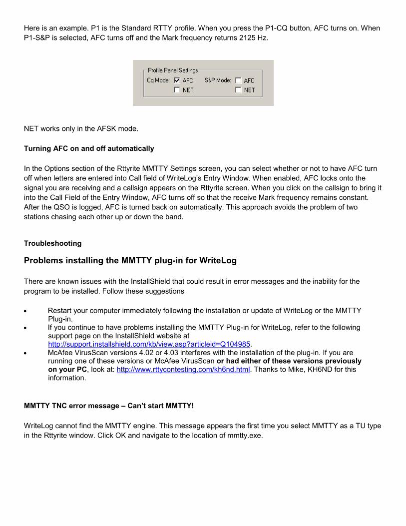
Here is an example. P1 is the Standard RTTY profile. When you press the P1-CQ button, AFC turns on. When
P1-S&P is selected, AFC turns off and the Mark frequency returns 2125 Hz.
NET works only in the AFSK mode.
Turning AFC on and off automatically
In the Options section of the Rttyrite MMTTY Settings screen, you can select whether or not to have AFC turn
off when letters are entered into Call field of WriteLog’s Entry Window. When enabled, AFC locks onto the
signal you are receiving and a callsign appears on the Rttyrite screen. When you click on the callsign to bring it
into the Call Field of the Entry Window, AFC turns off so that the receive Mark frequency remains constant.
After the QSO is logged, AFC is turned back on automatically. This approach avoids the problem of two
stations chasing each other up or down the band.
Troubleshooting
Problems installing the MMTTY plug-in for WriteLog
There are known issues with the InstallShield that could result in error messages and the inability for the
program to be installed. Follow these suggestions
• Restart your computer immediately following the installation or update of WriteLog or the MMTTY ......Plug-in.
• If you continue to have problems installing the MMTTY Plug-in for WriteLog, refer to the following ......support page on the InstallShield website at ......http://support.installshield.com/kb/view.asp?articleid=Q104985.
• McAfee VirusScan versions 4.02 or 4.03 interferes with the installation of the plug-in. If you are ......running one of these versions or McAfee VirusScan or had either of these versions previously ......on your PC, look at: http://www.rttycontesting.com/kh6nd.html. Thanks to Mike, KH6ND for this ......information.
MMTTY TNC error message – Can’t start MMTTY!
WriteLog cannot find the MMTTY engine. This message appears the first time you select MMTTY as a TU type
in the Rttyrite window. Click OK and navigate to the location of mmtty.exe.

Rttyrite error – Com port not available
The COM port selected in the Ports menu of the Rttyrite window is already in use. The port may already be in
use by WriteLog for either radio control, CW, or by some of other device.
• First confirm the port is not in use by another program. • If the port is not in use by another program, then go to the Setup menu in the main WriteLog
......window and select Ports. Make sure the port you are requesting in Rttyrite is not already in use for
......radio control or CW. If this is the case, clear the port and set the port in Rttyrite again.
Unable to select FSK in MMTTY set-up
• The FSK options are grayed out in the Misc tab screen of MMTTY Setup. • Go to the Rttyrite window and to the Ports menu and select the port to be used for FSK.
No receive audio
• No receive audio in your FFT or XYScope displays. • Good audio when using the MMTTY program by itself.
Solution:
• WriteLog may be looking at the wrong channel of the sound card for receive audio. • Make sure you have the correct channel set in MMTTY Setup | Misc tab, then go to the Radio menu
on the main WriteLog screen and select: “This Window is Radio Right”.
Unable to transmit RTTY
Solution 1:
• Cursor must be in the WriteLog Entry Window in order to transmit RTTY from either the function ......keys or live at the keyboard with ALT-K.
Solution 2:
• Unable to transmit any of the RTTY messages using the function keys and you are not using radio ......control.
• Make sure the mode is set to FSK in WriteLog. The button to the left inside the Entry Window ......should say FSK, even if you are using AFSK. If it doesn't say FSK, click the button with your ......mouse and another window opens where you can select FSK.

Unable to send macros using the F-Keys
• Using AFSK and unable to transmit using the function keys programmed with macros.
Solution:
• Check “LSB is really FSK” in the Bands menu in the main WriteLog screen.
MMTTY operation slow or locks up
WriteLog uses more memory than the stand-alone MMTTY program. MMTTY may run fine by itself, but when
used with WriteLog some of the settings in MMTTY may affect performance.
Solution:
• In MMTTY, click Option | MMTTY Setup | Misc tab, set Priority to Higher or Highest.
Delays between PTT and macro transmissions
• Set Priority higher, as above. • In MMTTY, click Option | MMTTY Setup | Misc tab and change the TX FIFO setting on the Misc tab
......of MMTTY Setup. • Make sure both radio control PTT and hardware PTT are not enabled at the same time. If you are
......using a hardware PTT device such as a RigBlaster or external interface and you are using radio
......control, go to the Ports options under the Setup menu in the main WriteLog window and set Comm
......PTT to “NO”.
Random transmit characters in the Rttyrite window
• In MMTTY, click Option | Setup MMTTY | Misc tab uncheck “Sound loopback”.
Transmission stops before the end of a macro
• Click Option | PTT timer, and set it to a longer interval.
MMTTY engines 1.63 & 1.64
The MMTTY engines that came with versions 1.63 and 1.64 have a known problem when used with WriteLog.
Pressing a function key to send a macro can cause the transmitter to key then suddenly un-key. This problem
was corrected in version 1.65. If you want to use an older version of the engine, version 1.62 works very well
with WriteLog.

Online Support
Detailed information on RTTY contesting with WriteLog and specifically, using the MMTTY Plug-in for WriteLog
can be found at http://www.rttycontesting.com.
Scot Herrick, K9JY also has a website dedicated to using WriteLog at http://www.k9jy.com/.
MMTTY and DX4WIN
MMTTY and DX4WIN on One Computer
MMTTY and DX4WIN on Two Computers
General Lessons Learned
DX4WIN and MMTTY on One Computer
The information in this topic is provided by K8UT, from a document called "Cross-Connecting MMTTY with
DX4WIN." Larry, provided this document on Jan. 13, 2004.
Here is a link to the DX4WIN software, http://www.dx4win.com/. DX4WIN works with the standard version of
MMTTY, whether you use the hardware or software interconnect method.
There are two ways to set-up hardware and software so that DX4WIN interacts with MMTTY to copy RTTY.
These methods are called hardware interconnect and software interconnect.
These instructions show how to control PTT with a serial port, but you can use VOX to reduce the number of
ports needed for hardware interconnect to two and for software interconnect to zero.
You can operate either FSK or AFSK mode using MMTTY and DX4WIN. The FSK signal is found at the
MMTTY serial port.
Hardware Interconnect
Hardware interconnect requires three serial ports in the computer. Two of the serial ports are connected with a
null modem cable so DX4WIN can communicate with MMTTY to receive and to transmit AFSK. The third serial
port provides DTR/RTS for PTT.
For simplicity, COM 1 is the PTT line, COM 2 is the MMTTY RTTY serial line, and COM 3 is the DX4WIN
RTTY serial line. You may use whatever assignments are convenient to you.
• Connect COM 1 to the transceiver PTT connection through an interface such as that shown in the ......topic PTT Using a Pin on a Serial Port.
• Connect COM 2 and COM 3 with a null modem cable, as described in the topic Use MMTTY as a ......Modem.
• Receive connection: connect the "mic in" on the sound card to "audio out" on the rig. • AFSK transmit connection: connect the "line out" or "speaker out" from the sound card to "mic in" on
......the transceiver. Read the topics Prepare for FSK and Transmit a Clean Signal.

Software Interconnect
The software interconnect method requires only one serial (COM) port, used for PTT control. A free software
program replaces the ports that communicate between DX4WIN and MMTTY (COM 1 and COM 2). This
program is available at http://www.mixw.net/related.htm. However, this software only works with Windows
XP and Windows 2000. It may work with future Microsoft operating systems, but it does not work with
Windows 95/98/ME.
Lessons Learned
Larry, K8UT, shares some lessons that he learned when configuring and running DX4WIN and MMTTY on a
single computer.
1. Do not open the DX4WIN PSK window when running MMTTY, because the two programs fight for ......control of the sound card in your computer. To switch from RTTY to PSK, first shut down MMTTY, ......then open the DX4WIN PSK window.
2. DX4WIN RTTY settings MUST be "always in immediate mode" for the DX4WIN macros to work ......properly. Click File | Preferences | RTTY | Always in immediate mode to make this work.
3. The MMTTY "Disable window" setting will minimize the screen space required by MMTTY, yet still ......allow you to see the tuning window. It also eliminates the confusion created when seeing two sets ......of receive and transmit text (one set from MMTTY, one set from DX4WIN). Do not disable the ......window during testing and debugging, because it is very helpful to see what text is flowing back & ......forth between MMTTY and DX4WIN.
4. In transmit mode, DX4WIN has a very limited transmit buffer with no backspace or delete key. This ......is why I use MMTTY in stand-alone mode for everyday QSOs.
MMTTY and DX4WIN on Two Computers
This section is an application of the topic Use MMTTY as a Modem, but since it has been worked out for
DX4WIN, we present it here. The two computers will be named PC1, running DX4WIN, and PC2, running the
standard version of MMTTY.
PC1
Start DX4WIN on this computer. Use the following settings for DX4WIN.
• Preferences | Tab = RTTY. • Type = REGULAR. • Com = (a serial port available on PC1). • Baud Rate = 9600. • Flow Control = RTS/CTS. • Data/Parity = 8 bits/no parity. • Options selected: Always in Immediate mode; Show function keys. • Save changes and exit DX4WIN.

PC2
Start the MMTTY engine (Version 1.61b or later). Use the following settings for MMTTY.
• Click Option | Setup TNC Emulation
• Port = (a serial port available on PC2) • Baud = 9600. • Data length = 8 bits. • Stop = 1 bit. • Parity = None. • Flow control = CTS. • TNC type = TNC241. • Local echo = After Sending. •
Use MMTTY to select the port to use for PTT, see PTT Using a Pin on a Serial Port. It is also possible to use
VOX control of PTT, or to have MMTTY send commands to a radio, but this requires an additional serial port in
PC2, see Software Control of PTT.
MMTTY can control PTT with an additional serial port, see PTT Using a Pin on a Serial Port.
General Lessons Learned
Here are some general lessons learned by K8UT, for any application of MMTTY and DX4WIN.
1. Use the T command in a macro to put MMTTY/DX4WIN into transmit mode, but put it at the END of ......a macro string.
2. Use the \ to revert to receive mode when you want to automatically shift from transmit back to ......receive at the end of a macro.
3. Use DX4WIN's Function labeling feature to make life easier. 4. Use the same keys for the same functions in CW, PSK and RTTY. 5. If you decide to operate ALL RTTY through the DX4WIN transmit window, clear the macros in
......MMTTY so that you don't hit a function key when MMTTY is the "active" window, causing you to
......inadvertently send a whole stream of junk. 6. If you decide to operate both MMTTY transmit and DX4WIN transmit, coordinate the macros so
......that similar function keys send the send information.

MMTTY and N1MM Logger Download, Configure, and Test MMTTY
-Download MMTTY
- Configure MMTTY
- Test MMTTY
Configure N1MM Logger for MMTTY
The Digital Interface
Set-Up Menu Selections
- Selection: MMTTY
Keyboard Assignments
Mouse Assignments
Configuring the Entry Window Function Keys
Macro Keys
- The MMTTY Interface
Set Up the Digital interface
Make a RTTY transmission
Automatic Name Lookup
Output Received Data to a Text File
SO2R (Single Operator, Two Radios)
Other Features
N1MM Logger is a freeware program designed to do contest logging and some general logging for CW, SSB,
RTTY, PSK63 and PSK31. The digital portion of the program is written by Rick, N2AMG. The underlying
logging program is written by Tom, N1MM. More information can be found on the N1MM logger website at
http://www.n1mm.com.
N1MM logger operates RTTY with MMTTY. Features like profiles, which are available in MMTTY, are also
available when using N1MM logger. This topic only discusses features related to MMTTY and N1MM Logger,
not features that are regularly available in N1MM Logger.
If you have a problem, please do the following:
• Check for a program update at: http://www.n1mm.com. • Check the latest version of the N1MM logger Help. • Review the N1MM Logger Help chapter, RTTY support. • Review the digital part of the Frequently Asked Questions. • Ask for help on the N1MM logger Yahoo users group.
Download, Configure and Test MMTTY
If you have N1MM Logger, the next step is to get a copy of MMTTY, configure it, and test it.

Download MMTTY
• Download the current release of MMTTY from: http://www.amateur-radio.ca. • Get 1.64 or a later version. • Run the setup program and install MMTTY in your computer in its own directory. • The N1MM logger NewExe file, which contains the latest update from the program, contains the file
......XMMT.ocx. XMMT.ocx is needed for MMTTY version 1.64 or higher and should be in the N1MM
......Logger directory. • If you do not have XMMT.ocx in the N1MM logger directory, get an updated version of N1MM
......Logger.
Configure MMTTY
The next step is to configure the software. First, you must decide whether you are using FSK or AFSK.
FSK Keying
1. In the main Config area of N1MM Logger Digital Pane:
• Select MMTTY as your Interface type
• Select the path to your MMTTY folder; this does not have to be the same folder as the N1MM ......Logger.
• Select the MMTTY Interface Type (FSK)
2. In the Main Config area of N1MM Logger, Hardware pane, place a check mark under the digital column that
you are using for the digital port.
3. Save and exit the Hardware pane. If MMTTY is already loaded you will probably get an error message about
not being able to open port xxxx.
4. Open the N1MM digital Interface and when MMTTY Loads select: Settings/Setup MMTTY
5. Click the TX Settings pane in the MMTTY Setup area and set the COM port that you will be using for FSK
keying and Data.
6. Close the MMTTY Setup Window and then close the N1MM Logger Digital Interface to have MMTTY save
the settings.
7. From this point, when the digital Interface loads It does NOT pass the port info to MMTTY. MMTTY loads the
Com settings from is own settings file.
Using the RIGblaster interface for FSK with the N1MM/MMTTY combination
The default for FSK via MMTTY is TxD. You'll need to change the jumper in the Rigblaster. Also, make sure
you get MMTTY working as a standalone first. Then you should just be able to specify MMTTY in the digi
interface config in N1MM and it should take off. If you are lucky enough to have a radio where PTT is asserted
via radio control ( Kenwood is one) then leave the PTT unchecked in the port setup and checked in the PTT via
rig control portion.

AFSK Keying
1. In the Main Config area Digital Pane of N1MM Logger:
• Select MMTTY as your Interface type. • Select the path to your MMTTY folder, which does NOT have to be the same folder as N1MM
......Logger. • Select the MMTTY Interface Type (AFSK).
2. In the Main Config area Hardware pan put a check mark under the digital column that you are using for the
digital port.
In order to use two copies of MMTTY you need to have two different keying COM ports set up for MMTTY to
use. The second COM port must be a higher number than the first.. More information can be found in the
SO2R chapter of the N1MM Logger Help file.
Test MMTTY
MMTTY is a stand-alone application, so testing can be done outside N1MM logger. Start up MMTTY by itself
and run it according to the instructions in this Help file.
Configure N1MM Logger for MMTTY

• Start the N1MM Logger application. • On the N1MM Logger Main Window click Config | Configure Ports | Telnet Address | Other. • Select the Digital Modes tab. • Select MMTTY/PSK.
The Digital Interface
This is the N1MM Logger Interface using the MMTTY RTTY Engine. The Digital Interface appears when it is
selected under Window in the Entry Window.
If a second RTTY port is configured, a menu item appears at the top of the Digital Interface allowing you to
open the second RTTY interface..
The exact frequency is displayed in the Digital Interface caption (rig(+/-)audio).

The MMTTY interface has two windows :
• Top window - This is the receive window. This window works mostly the same as the one for ......standalone MMTTY.
• Bottom window -This is the transmit window, which also works the same as it does in standalone ......MMTTY.
Operating Features:
• Callsign Textbox and Grab - When a callsign is encountered in one of the receive windows ......(starting with and followed by a space) it will appear in this textbox. When you press the Grab ......button the callsign transfers over to the main logger window. The grab callsign window holds the ......last 4 callsigns seen in the RX window. The most current one is at the top and is highlighted. Dupes ......are shown in the grab window.
• Macro buttons - There are macro buttons on the digital interface for preprogrammed messages. ......Configure these macros in the Digital Interface window under 'Setup, Settings' or by right clicking ......them to bring up the Digital setup screen.
• Clr RX - Clear the receive window
• TX - Start the RTTY transmission, the transceiver is keyed.
• RX - Stop the RTTY transmission, the transceiver changes back to receive. • Grab - Transfer the selected callsign in the Callsign textbox to the callsign field on the main logger
......window. Once the callsign is filled what ever you click on next will fill the next box to have info
......entered in. The mouse is the only way to do this. • Scroll back - To scroll back , pause the RTTY screen by clicking the green stripe on the left side of
......the screen and scroll back the last 2000 lines of text.
Set-Up Menu Selections
Selection: MMTTY
Click Setup at the top of the MMTTY/PSK window to see the setup menu. Here are the choices:
• Settings - Setting up the digital interface, see chapter below (Setting up the Digital interface) • SoundCard (only on first open MMTTY window) • Receive Mixer - Shows the Record control mixer dialog from the Windows operating system. This
......menu item is only visible when MMTTY is selected. • Transmit Mixer - Shows the Play control mixer dialog from the Windows operating system. This
......menu item is only visible when MMTTY is selected. • Setup MMTTY - Shows the MMTTY setup tabs. This menu item is only visible when MMTTY is
......selected. • AFC On/Off with CQ - Set this to turn on AFC with CQ message or TU messages • NET On/Off with Run Change - Turn on/off MMTTY's Net function in S&P and off in Running mode • Auto Update TRX Offset w/Mark Freq. - Update the transceiver offset whenever the Mark frequency
......changes. This logs the true mark frequency when you are using AFSK RTTY. • RTTY - Select RTTY as mode • PSK - Select PSK as mode • Open 2nd RTTY Window - Open a second RTTY window. In Configurer, under the Digital Modes
......tab, you must choose a second Digital Interface. • Help - View help file
Keyboard Assignments
• Alt-T - Toggle TX/RX. Put the focus on the TX window of the active interface.
• Alt-G - Grab callsign.
• Ctrl-Arrow - When two radios are configured and two digital windows are open, pressing CTRL-ARROW swaps from one active Digital Interface to the other. Digital Interface 1 follows radio 1 (bandmap A). Digital Interface 2 follows radio 2 (bandmap B).

Insert key Assignments
Mode Enter Sends
Message(ESM mode) INSERT key or ; key does the following:
RUN
and
S&P
OFF
1. Grab Callsign from call list if callsign field empty otherwise use call in
callsign field.
2. Prefill the Exchange Boxes
3. NO DUPE: Send F5 (Hiscall) + F2 (Exchange)
or
DUPE: Sends Nothing
4. Put cursor in next exchange field (Example: Sect)
RUN ON
1. Grab Callsign from call list if callsign field empty otherwise use call in
callsign field.
2. Prefill Exchange Boxes
3. NO DUPE: Send F5 (Hiscall) + F2 (Exchange)
or
DUPE
WorkDupes checked: Send F5 (Hiscall) + F2 (Exchange)
WorkDupes not checked:Send F6(Dupe)
4. Put cursor in next exchange field (Example: Sect)
Highlight F8 button
S&P ON
1. Grab Callsign from call list if callsign field empty otherwise use call in
callsign field.
2. Prefill Exchange Boxes
3.NO DUPE: Send F4 (Mycall)
or
DUPE
WorkDupes checked: Send F5 (Hiscall) + F2 (Exchange)
WorkDupes not checked:Send F6(Dupe)
Once exchange entered INSERT sends F5-F2
Pressing INSERTagain continues to send F5-F2
4. Put cursor in next exchange field (Example: Sect)
Press Insert or ; and if the callsign field is not empty, F5+F2 text will be sent. If the callsign field is empty this
also grabs the callsign from the call list.
Upon grabbing a callsign from the call list, that callsign is deleted from the grab list.
If the callsign in the callsign field in the Entry window is equal to the callsign in the received text, the call in the
Entry window does not get placed into the call list.

Mouse Assignments
• Left mouse key click: • Single click on a callsign to put it in the Callsign field on the Entry Window dialog. • Single click on Exchange info etc. to put it in the Exchange field on the Entry Window dialog.
Note: The callsign field must be filled first, before the other fields!
• Right mouse key click on RX or TX window: • brings up a menu: • Clear RX - Clear the receive window. • Clear TX - Clear the transmit window. • Output to Text File - Output the received text to a text file named RTTY1.txt. • LTRS/FIGS Convert - Whenever you pass the mouse cursor over a word in the receive pane, that
......line shows the same word with every character in the opposite case (so 599 becomes TOO, etc.). • Help - Show the help file for this window.
• Right mouse key click in GRAB window: • brings up a menu: • Clear List - Clear the entire grab window. • Clear Selected Call - Clear the selected call in the grab window.
Configuring the Entry Window Function Keys
• In the N1MM Logger Main Window click Config | Edit the Digital Buttons, then put in the text you ......want to send. Here is an example.

Macro Keys
• There are a maximum of 24 extra macro keys possible on the RTTY interface. • A right click on the macro buttons brings up the Digital Setup screen where the macros can be
......configured. • These extra 24 function keys support all the macros but do not support Running Mode or 'Search
......& Pounce' (S & P) mode. • The buttons in the PSK window and the function keys on the Entry window support Macro key
......substitution. • Macros and examples are found in the N1MM Logger Help file on the Macros page.
The MMTTY Interface
• The text entered for each macro button is sent when the button is pressed, as long as you are in ......transmit mode. See the MMTTY Macros topic for commands you can put into the macros to control ......PTT.
• There is no special abort macro for use with MMTTY. Press the ESCape key to stop transmitting. • The TX and RX buttons control PTT when you are typing in the transmit window. • MMTTY loads the settings it had when the it was last closed.
Set Up the Digital Interface
Click Settings to see the following screen.

• PSK Waterfall Color palette - You may select the colors for the waterfall display. The Default button ......changes the colors back to the default colors. The color Palette is active when the User Defined ......selection is selected in the Waterfall Color Box.
• Waterfall Color - Select among
• Grey Scale
• Default Color • User Defined
• Smoothing
• Gain - Sets the amount of signal gain for the Spectrum/Waterfall. • Squelch Speed -This is how quickly the squelch shuts off on noise. Select between Slow, Fast and
......Variable. When using variable select a value between 0 and 200. • Squelch Level -The level at which the interface should start printing decoded signals. • AFC Search Range -How far in Hz. the interface will track a drifting signal. • Use Doppler AFC
• RX Search Range -How far in Hz. the interface will look to lock onto a signal when you click on a ......signal in the waterfall or spectrum.
• RX/TX Font Size -Font size for the receive windows and the transmit window. Select from 8pt, 10pt, ......or 12pt.
• PSK/RTTY Window Colors - The PSK and RTTY receive and transmit window background colors. • SndCard Clock Adj - Sound card clock adjustment. • CW ID - Check this box to send the string entered in the field behind it (Enter CWID String) after
......every transmission. Only for use with external TNCs . • PSK Soundcard Select - Select the sound card to be used if you have more than one sound card in
......your computer. • RX Window Font Selection - Change font and size. Press the 'Set Font' button to get the selection
......window.
• Digital Macro Set - Update the macro definitions and button texts.
1. Select an interface from the dropdown menu. Choices are: PSK, MMTTY 1, Other 1, MMTTY 2, ......Other
2. Click on the macro button to be updated. 3. Type the macro text in the field Macro Text. 4. Type the text on the button in the field Macro Caption. 5. Click Save Macro. The selected macro caption text will be shown on the button.
• Available macros are shown in the box 'Available Macros'. First select a macro button to see them ......all.
• Load Macros - Load saved macros from a saved file (*.mc) to the Digital Macro Set. • Save Macros - Save macros from the Digital Macro Set to a file (*.mc). • # of Macros - select the number of macro buttons. You can select 0, 8, 16 or 24. • Macro Text - Area where to create the macro text for the selected macro. • Macro caption - Macro caption from the button. • Available Macros - shows the available macros. Click on a macro to transfer it to the macro text
......area. • Save Configuration - save the made configuration changes. If the changes made should not be
......saved close the window with the X at the upper right.
The Save Configuration Button on the bottom of the form saves the changes. Changes take effect as soon as the setup area closes.
Make a RTTY Transmission

• Minimize the Logger Telnet/Packet window to make room for a new RTTY screen. • Select "Window | Digital Interface" and you will see the Digital interface screen below. The Digital
......Interface screen can be positioned and resized. • Two more windows appear: • The MMTTY Engine window (how it will appear depends on the settings in the Configurer). • The Digital Interface window. • Left click on a call to grab the callsign. Right click on the RX and TX windows to see a menu. • Press Insert to Grab the highlighted call and sends Hiscall followed by the Exchange button. If the
......digital Interface is not loaded it works normally. • Double-click on a callsign in the callsign box from the Digital interface to send that call to the Entry
......window. • If the program recognizes a callsign, it is automatically highlighted. There must be a space before
......and a space after the callsign. If the first thing on a new line in the digital interface window is a valid
......callsign, it is not highlighted or added to the grab list because it does not have a space before it. • The red and green lines show roughly where the spectrum works the best. The Red line indicates
......center 1500 Hz. and the green lines show 2000 Hz. and 1000 Hz.
Automatic Name Lookup
N1MM Logger can look up the name of a station entered in the Callsign field.
• Import a callsign versus name text file. • The famous 'Friend.ini' file used in the WF1B program is one of these. • A text file can also be imported, using the following format: • Callsign Comma Name
• Example: N1MM,Tom
• See the import example below. • Select the menu item: Call History Lookup under Config. • Use the {NAME} macro to send the name. • Note: Press the space bar to look up the name.
Here is how to import the Friend.ini file from the WF1B program.
• Select File | Import | Import Call History. • Select your Friend.ini file by changing Files of type: to All Files (*.*). If you do not do this, you will
......only see files of type txt. • Select the Open button to perform the import. • Importing info in this table will delete the original contents of the table. There is no merge option! • If you want to add (merge), You must first export the Call History file (File | Export | Export Call
......History ), merge the data outside the program wit a text editor like Notepad, and then import this
......new file as shown above. • In the bottom pane of the Entry Window you can see the number of callsigns in the name file.

Output Received Data to a Text File
If you record received data to a file, then you can go back through them for information you may have missed.
There are two ways to output received data to a file:
1. Left click in the RX window and select output to Text File
2. You can also do this in MMTTY, but it is harder, see the Operating Techniques topic.
SO2R (Single Operator, Two Radios)
N1MM logger supports SO2R for RTTY. You can use any combination of either two MMTTY windows, two
TNC windows or one of each for SO2R operation. Information about MMTTY sound card setup and SO2R can
be found in the N1MM logger Help file in the SO2R chapter.
Other Features
• Press control while single clicking on a call to force the call into the Entry window. • In ESM mode, don't simulate space bar, just set focus to the Entry Window. • Hyphens (-) are stripped from exchange elements. • CQ Repeat time when using MMTTY counts from when the sending stops. • The {RX} macro string has a CR/LF at the end for easy recognition. • You cannot grab a callsign from the receive window while transmitting. • Linefeed characters in incoming text are replaced with CR.
This topic of the MMTTY Help file was written by Thomas Tinge, PA1M.
Use MMTTY as a Modem
Hardware Setup
- Two Computers
- One Computer
- Null Modem
Software Set-up
MMTTY can function as if it were a terminal node controller, or modem. This mode was useful when there were
other programs that could do logging or contesting, but required a modem to operate RTTY. This feature has
remained in MMTTY. Some contest and logging programs make provision to use MMTTY in the same
computer as the contest or logging program, and no longer require work-around. Others use this technique.
Hardware Set-Up
You can use MMTTY as a modem by using two computers, or one computer with two serial ports that can
operate at the same time.

Two Computers
One computer runs the contest program that expects a modem to be connected to a serial (COM) port. A
second computer runs MMTTY, and specifies a COM port as MMTTY's output of decoded data. Connect the
COM ports of the two computers with a null modem (crossed wires).
One Computer
The same computer runs both the contest program and MMTTY. In the contest program, specify a serial
(COM) port as the place where a modem is attached. In MMTTY, specify a different serial (COM) port as the
output of MMTTY. Connect these two ports on the same computer with a null modem.
Null Modem
A null modem is a pair of wires crossed so that the output of each computer is connected to the input of the
other. For a DB-25 (25-pin) or DB-9 (9-pin) COM port connector, pins 2 and 3 are crossed. Pin 2 on the first
end of the cable is connected to pin 3 on the second end of the cable, and pin 3 on the first end is connected to
pin 2 on the second end. This setup is not the "official" way to make a null modem. A real null modem cable
has other connections as well, but for MMTTY, these are the only connections you need. You can purchase a
standard null modem cable at Radio Shack.
Software Set-Up
Set-up MMTTY as a modem using the computer on which it is running.
Click Option | Setup TNC emulation, and view the following display.

The port definitions are straightforward. Both computers must use the same settings for baud, data length, flow
control, stop bits, and parity. Port numbers can be different, as long as the correct ports are connected with the
null modem. You can make MMTTY emulate an MFJ TNC 241, a KAM, or a Baudot TU.
To see MMTTY's output on the computer that is running MMTTY, you may have to play with the echo
selection.
Decoded characters should appear in your contest program once MMTTY is running.
MMTTY can control a transceiver using software control, key PTT via a port, or operate FSK. Even though you
control the MMTTY modem computer from another computer as if it were a KAM, the modem computer can do
most of the things that MMTTY can do.
MMTTY With Different Transceivers
Ten-Tec Omni VI
Yaesu FT-1000 Mark V
Yaesu FT-100D
Icom IC-706
IC-756 and IC-756 Pro
Kenwood TS-870
As MMTTY has spread around the world, users have gotten different transceivers to work with it. Follow the
procedures shown elsewhere in this Help file, and check here for specific problems that have been solved for
your transceiver. See Radio Command, Use a Serial Port to Control PTT, and FSK for a general approach to
many interface questions.
This topic discusses problems and solutions by model.
Ten-Tec Omni VI
The Omni-VI and VI+ operate the same way with MMTTY.
Radio Command for AFSK Operation
The Omni VI is one of the radios already set up for Radio Command in MMTTY. Set the xx= window at the top
right of the Commands block. The default setting for an Omni VI is 04.
Most Yaesu Transceivers
• Use Packet mode and Packet input to use the narrow CW filter and operate AFSK. • For FSK, use the RTTY input.

Yaesu FT-100D
• Operate T/R via Radio Command. • Frequency display in Radio Command is incorrect. • VOX operation is not available in digital mode. • SSB mode allows VOX but not the narrow filter.
Icom IC-706
• Computer interface does not control T/R switching. There is no command for this.
Icom IC-756, IC-756-Pro, ProII and ProIII
• Use the ACC1 connector on the rear panel to connect the PC to the radio. • Both radios run cool at full power in RTTY.
ACC1 Pinouts
1 RTTY keying (FSK)
2 GND
3 PTT
4 Modulator input
5 AF detector output
6 Squelch output
7 13.8 V out
8 ALC voltage input
AFSK:
• No access to narrow filter in SSB mode. • Set microphone gain to show no ALC. • Turn off speech processor.

FSK:
• Narrow filters work. Press RTTY button briefly to select RTTY-N. • ALC meter reading is full-scale ALC.
Set FSK mode:
1. Press RTTY button on front panel. 2. Access the menu, and select either HIGH or LOW tones for use. 3. Set MMTTY to use the same tones (same mark frequency).
There is a NORmal and REVerse option in the menu. NORmal is the default. To work an inverted (upside-
down) signal:
• Press and hold the RTTY button on the IC-756 to select RTTY-R. • Retune the inverted signal.
Filter Selection:
• Use FILTER button on front panel to select from three selectable filters (FIL-1, FIL-2 and FIL-3) • set FIL-1 as 2 kHz. for general listening, FIL-2 to 500 Hz. for cutting down noise, or when in QSO,
......and FIL-3 to 250 Hz. for contesting. • Use the TWIN PASS BAND TUNING to create even narrower filters (or even shifted filters) in any of
......the three positions.
Rig Control (Radio Command)
• Set menu BAUD rate to 9600. Autobaud has caused problems for some hams. Remember to set ......MMTTY's baud rate to the same value.
• Consult the menu for the CI-V address. This is the four digit number needed for MMTTY Radio ......Command procedure (Option | Setup MMTTY | TX tab | Radio Button | xx= window).
IC-756 Pro
AFSK
• Select USB-D or LSB-D to operate AFSK; the microphone will be disconnected, and audio will only ......come from the rear input. Use this input for the computer sound card.
FSK:
• RTTY button is labeled CW/RTTY. A quick press toggles between CW and RTTY. • Select either HIGH or LOW tones in the menu. • RTTY twin peak filter and built-in RTTY decoder must use HIGH tones. • If you select LOW tones, then press the RTTY FILTER button, or select the inbuilt decoder, this
......automatically selects HIGH tones in the menu. To return to LOW tones, access the menu and re-
......select LOW tones.

Kenwood TS-870
• Use the back panel (ACC-1) input. • PTT input is Pin 9
• Do not use software command for PTT with AFSK.
Profiles
The Profiles Concept
Define a Profile
Remove a Profile
Tailor a Profile in USERPARA.ini
Standard Profile
The HAM default in MMTTY makes it easy to return to a basic set of RTTY operating parameters. However,
new modes, contest conditions, and other situations make it nice to be able to define different operating
parameters. MMTTY has a feature called Profiles, so it can remember different sets of starting conditions. You
can always change the parameters one at a time in MMTTY, profiles just makes it easy to make a number of
changes at once.
The Profiles Concept
Profiles let the user control a number of parameters at one time. Click Profiles, then select the profile you want
to use. If the profile includes new parameters for the HAM button, these new values are used when you click
the HAM button. The profile "Standard RTTY" brings you back to MMTTY as it came in the original download.
You can create new profiles, as well as use those provided.
Define a Profile
To define a profile, start MMTTY and then set parameters any way you choose.
When you have the parameters set, click Profiles | Assign menu, and select the item that you want to assign
for this profile. You will name the profile on the next screen. When you select this profile in the future, all
parameters will be as they are when you set up the profile.
You may define up to nine Profiles, although it is strongly recommended that you leave Standard RTTY
unchanged.
Remove a Profile
To remove a profile, click Profile | Delete and choose the one you want to delete.

Tailor a Profile in USERPARA.ini
It is possible to preset every parameter in MMTTY.
All parameter values are stored in a file called UserPara.ini, in the MMTTY folder. You can edit this file with a
text editor, such as Notepad, but it must be saved in txt format with exactly the same name, UserPara.ini.
You can change any parameter to any legal value. If you do not want to save a parameter, but instead you
want MMTTY to leave the parameter at whatever value it has before you select this profile, delete the line for
that parameter from UserPara.ini.
For example, define a new Profile (call it "taps") to change the number of taps in the BPF (RXBPFTAP). You
do not want the shift width to change. Erase the line in "taps" that reads "DefShift=1.700000e+02." Now,
DefShift is no longer defined in this profile, "taps." Put the value for number of taps in "RXBPFTAP = ". When
you select profile "taps," it will change the number of taps to whatever you set, but it will not change the shift.
Standard Profile
You may want to change the standard RTTY profile if you find that one of the variables controlled by
USERPARA.ini must be adjusted every time you start MMTTY. Edit USERPARA.ini, and change the first
profile, where Name=Standard RTTY. You can set AFC, BPF, UOS, REV., PTT reverse, and other parameters
to the way you want them. Now, if you change any of these yourself, or by using a different profile, when you
click Profiles | Standard RTTY, they are reset to the values in this profile. Remember, though, that "Standard
RTTY" was provided to give you a standard working setup in case you make changes that prevent you from
using MMTTY.
USERPARA.ini
The following table shows the variables that can be memorized in a profile.
0 means "off," and 1 means "on."
Spelling must be exact, including upper/lower case letters.
Large numbers are written in scientific notation. Example: 170 = 1.700000e+02.
Main display mark frequency cannot be set, but HAM default mark and shift can be set.
Name Profile name on Profile menu.
Enabled Is profile enabled on Profile menu? 0=gray, 1=black.
AFC AFC button on/off on main display
AFCFixShift Shift setting on AFC/ATC/PLL tab and main display. 0=Free,1=Fixed,
2=HAM, 3=FSK
AFCSQ AFC SQ setting on AFC/ATC/PLL tab.

AFCTime AFC Time setting on AFC/ATC/PLL tab.
AFCSweep AFC Sweep setting on AFC/ATC/PLL tab.
UOS UOS button on/off on main display.
TxNet NET button on/off on main display.
TxDisRev Disable Rev on/off on Tx tab.
LimitDxGain Limit amp. gain setting on Demodulator tab.
LimitOverSampling Limit oversampling on/off on Demodulator tab.
ATC ATC on/off on AFC/ATC/PLL tab and main display.
ATCTime ATC time setting on AFC/ATC/PLL tab.
Majority Majority Logic on/off on Decode tab.
IgnoreFreamError Ignore frame error on/off on Decode tab (misspelled).
SQ SQ button on/off on main display
SQLevel Squelch setting on AFC/ATC/PLL tab and main display.
DefMarkFreq HAM default mark frequency on Demodulator tab.
Defshift HAM default shift frequency on Demodulator tab.
DefStopLen Stop length on Decode tab.
OutputGain Digital output setting on Tx tab.
TXECHO Same as TXloop.
TXloop Sound loopback on Misc tab. 0=OFF, 1=Int, 2=Ext. (SAT)
TXBPFTAP Tx BFP taps on Tx tab.
TXLPF Tx LPF on/off on Tx tab.
TXLPFFreq Tx LPF freq. on Tx tab.
TXWaitType 0= Char. Wait,1=Diddle Wait, 2= Both Wait, 3=Disable Wait
TXCharWait Char. wait setting on Tx tab and Tx menu.
TXDiddleWait Diddle wait setting on Tx tab and Tx menu.

TXCharWaitDiddle
TXRandomDiddle Random Diddle on/off on Tx tab.
TXWaitTimerDiddle Wait timer for random diddle on/off on Tx tab.
Rev Rev button on/off
ShiftFreq Shift frequency on Demodulator tab and main display.
RXBPF BPF on/off on Demodulator tab and main display.
TXBPFTAP BPF Tap setting on Demodulator tab.
RXBPFAFC BPF AFC connection on Demodulator tab.
RXBPFFW BPF FFW setting on Demodulator tab.
RXlms LMS on/off on Demodulator tab and main display.
RXlmsDelay LMS delay on Demodulator tab.
RXlmsMU2 LMS MU2 (2u) setting on Demodulator tab.
RXlmsGM LMS GM setting on Demodulator tab.
RXlmsAGC LMS AGC on/off on Demodulator tab.
RXlmsInv LMS Inv on/off on Demodulator tab.
RXlmsTAP LMS Tap setting on Demodulator tab.
RXlmsBPF BPF on/off on Demodulator tab and main display.
RXlmsType 0=Notch unchecked, 1=Notch checked Demodulator tab.
RXlmsNotch Audio frequency of Notch 1
RXlmsNotch2 Audio frequency of Notch 2
RXlmsTwoNotch Two notches on/off on Demodulator tab.
DEMTYPE Demodulator type on Demodulator tab and main display. IIR = 0, FIR = 1,
PLL = 2
BaudRate Baud Rate on Decode tab and main display.
TTYBitLen Bit Length setting on Decode tab.

TTYStopLen Stop Length setting on Decode tab.
TTYParity Parity setting on Decode tab. None = 0, Even = 1, Odd = 2, 1 = 3, 2 = 4
SmoozType
SmoozOrder
SmoozIIR
Smooz
Tap Tap under FIR BPF demodulator on Demodulator tab and on main
display.
IIRBW BW under IIR demodulator on Demodulator tab and on main display.
pllVcoGain PLL VCO gain on AFC/ATC/PLL tab.
pllLoopOrder PLL loopLPF (IIR) order on AFC/ATC/PLL tab.
pllLoopFC PLL loopLPF (IIR) FC on AFC/ATC/PLL tab.
plloutOrder PLL output LPF (IIR) order on AFC/ATC/PLL tab.
plloutFC PLL output LPF (IIR) FC on AFC/ATC/PLL tab.
Diddle Diddle setting on Tx tab. None = 0, BLK = 1, LTR = 2.
TxFixShift Always fix shift on/off on Tx tab.
InvPTT PTT Invert logic on/off on Tx tab.
TXUOS Tx UOS on/off on Tx tab.

Record and Play Wave Files
Record Wave Files
Play Wave Files
Additional Wave File Controls
MMTTY can record files in Wave (wav) analog format and then replay them to itself. You can experiment with
different settings of filters, taps, and so forth, to see which combination does the best job of decoding the input
sound file. The input file will have all the noise it had when it first was received by MMTTY, so you can test
again and again with the same signal.
The playback appears at the sound card output, so you can try an external demodulator (for example, Hal P-
38) to compare with MMTTY.
Record Wave Files
To record data quickly:
• Click File | Record WAVE (mmv) immediately. • A check appears on the File menu next to Record immediately, and additional controls (see below)
......appear on the File menu. • When you are ready to end the recording, click File | Close Play/Record. • MMTTY automatically stores the file under a code name. The name is a number in this format:
......monthmonthdaydayhourhourminuteminute.mmv.
To record data to a file that you name:
• Click File | Record Wave (mmv) as... • A check appears on the File menu next to Record Wave (mmv) as... and additional controls (see
......below) appear on the File menu. • Name the file
• When you are ready to end the recording, click File | Close Play/Record. • The file is stored under the name you specified.
Play Wave Files
To play back data that are recorded:
• Click File | Play Wave. • A check appears on the File menu next to Play Wave and additional controls (see below) appear on
......the File menu. • A display appears that shows progress. The data are playing back. • You can stop the play on this display, or you can hide the display as it plays back.

Additional Wave File Controls
There are additional controls that operate during either record or play:
• Click File | Pause Play/Record to stop recording or playing the file but keep it ready to continue from ......that point.
• Click File | Rewind Play/Record to go to the start of the record or play file. • Click File | Close Play/Record to stop record or play. The recorded file is saved. • Pause the file and an additional command appears: Seek play position. This brings back the
......progress display, and you can move the slider to replay the part you want to replay.
It takes a second or two to select Pause. If you have recorded a very short file, it may be too short to allow you
to pause and then use seek. Make sure that a recorded file is long enough to allow you to click File | Pause.
Transmit a Clean Signal
Pay attention to how clean a signal you transmit before you go on the air. This is particularly important for the
digital modes. (1) when you operate using RTTY, the operator on the other end does not hear distortion of your
signal, in fact, the other guy may not hear you at all with his ears. (2) distortion can cause spurious signals that
are hundreds of Hz. away from your signal, so other RTTY operators on the band will have QRM.
AFSK operation is especially subject to distortion. Here are some points to consider if you use AFSK.
Unwanted Sounds
Disconnect the microphone from the transceiver each time you operate AFSK RTTY. You are really operating
SSB, and sounds over the microphone will be transmitted.
Windows also sends warning sounds to the sound card. As long as you do not operate VOX, these are seldom
a problem, since you are using MMTTY as the major program, and MMTTY does not use these sounds.
However, if you are doing something in the background, a beep from that program could cause a problem.
Other logging and contest programs may include sounds notifying you about DX announcements or needed
multipliers in a contest.
Audio Processing and Compressing
Turn off any audio processing and/or compressing in the transceiver, each time you operate RTTY. These
techniques sometimes enhance copy of the voice signal, but they specifically distort your signal. They are
unsuitable for RTTY and will cause spurious signals.
Voltage Divider
Use a voltage divider if it is needed. The audio out of a sound card is on the order of 5 volts AC. The
microphone input expects about 50 microvolts AC. This means that the sound card is 100 times higher in
voltage than the transceiver expects it to be. This usually does not damage the transceiver, but it definitely
overdrives the audio stage.

It is usually not possible to control this precisely enough with the Windows mixer controls.
Some Kenwood transceivers have a rear-panel audio input that already has a voltage divider, so they do not
need an external one. Most "computer interfaces," such as RigBlaster include this divider.
The schematic for such a divider is found in the topic Quick Start Set-Up.
Adjust Microphone Gain
Few hams today have oscilloscopes with which to monitor their signals, so adjusting the mic gain can be
difficult. If you have an ALC meter, GU0SUP suggests setting the microphone gain so that there is no
indication of ALC. ALC specifically distorts a signal by limiting it if it exceeds a threshold.
If you do not have an ALC meter, but you have a power meter, adjust the mic gain so that output power drops
below full power while you are operating RTTY. In fact, many transceivers recommend that you do not operate
them at full power for RTTY, so use the mic gain to do this. If you have a power output control, leave it at full
output, but decrease the mic gain to get reduced output. This will ensure that you do not overdrive the audio.
FSK
None of the above problems pertain to FSK. As long as your transceiver modulator is clean, you will transmit a
clean signal.
Mark and Shift Mark, Shift, and Space
- Where Are the Tones?
Reverse Shift
Nonstandard Shift
Fixed Shift
You should understand the concepts of mark and shift before operating RTTY.
Mark, Shift, and Space
Think of a RTTY signal as a continuous, constant -amplitude, suppressed-carrier signal that shifts back and
forth between two distinct frequencies. RTTY signals can also be seen as a combination of two CW carriers at
different RF frequencies, only one of which is on at any given time. The pattern in which the two tones are
transmitted is what codes the letters.
One of these RF frequencies is known as the mark frequency; the other RF frequency is known as the space
frequency. The difference between Mark and space is known as the shift. For amateur radio, the shift has
been somewhat standardized at 170 Hz. It is customary to refer to the mark frequency as the frequency you
are operating on. For example, if you say you are transmitting on 14085.00 kHz, that means your mark
frequency is 14085.00 kHz and your space frequency is 170 Hz away.

This brings up a question: Is the space frequency shifted 170 Hz. below the mark frequency, or 170 Hz. above
the mark frequency? The answer to this question is established by convention. The ham radio convention is to
operate RTTY on lower sideband, and to call one carrier the mark tone, and the other carrier, shifted 170 Hz.
(0.170 KHz.) below the mark tone frequency, the space tone. A shift above the mark frequency is called a
reverse-shift.
Where Are the Tones?
The standard for posting information on the location of a RTTY station is to post the mark frequency, but many
posts are in error. When you operate AFSK using a standard ham transceiver, and use LSB mode, things get
even more complicated. Here is an outline of what is happening:
• You are operating AFSK, LSB (transmit and receive). The transceiver frequency display shows the ......location of your suppressed carrier. That is the location where a tone of 0 Hz. would be transmitted.
• The transceiver shows a frequency of 14080 kHz. • You have MMTTY set to use the HAM defaults, with a mark frequency of 2125 Hz. (2.125 KHz.)
......and a shift of 170 Hz. (0.170KHz.). • You want to tell someone where your mark frequency is located, or you tuned in a station at this
......location, and you want to post its mark frequency. • The mark frequency you are receiving is actually 14080 KHz. - 2.125 KHz. = 14077.875 KHz. This
......last number is what you should post if you want to post the mark frequency on a DX Cluster. • Your space frequency is shifted down another 0.170 KHz. from your mark frequency, so your space
......frequency is on 14077.875 KHz. - 0.170 KHz. = 14077.705 KHz.
MMTTY can compensate for the fact that your mark frequency is not where your transceiver display reads out.
Read how to set this compensation in the topic Radio Command. Once you do this, you can see what happens
by setting your transceiver and then looking at MMTTY's frequency display. See what changes if you change
your mark frequency from 2125 Hz. to 1000 Hz. MMTTY knows your mark frequency, your transceiver's
frequency readout, and whether you are shifting for USB or LSB. With that information, MMTTY is able to
display the actual RF frequency of your mark tone in the MMTTY frequency window.
If you see an announcement where someone posts the correct mark frequency for a DX station, look at
MMTTY's frequency display (not your transceiver's display) and tune so that it reads the frequency you saw
posted. The DX station should be tuned in.
Reverse Shift
If you set your transceiver to use upper sideband instead of lower sideband, set MMTTY to reverse (Rev.) to
copy and send to most ham stations. With Rev., MMTTY compensates for the "upside down" signal by sending
mark where it would normally send space, and vice versa. Unless you check a box on the TX tab (Tx Tab), you
also transmit AFSK reversed.
Nonstandard shift
Sometimes stations use a shift of 200 Hz., but MMTTY can copy either shift automatically, and a station using
200 Hz. shift will copy your 170 Hz. shift as well. Even if MMTTY is set to receive only with 170 Hz. shift, 200
Hz. is close enough that copy will not be badly degraded.

Fixed Shift
You can set your transmit shift to be the HAM default value, no matter how the receive shift width changes.
See Tx Tab and look for "Always fix shift."
Demodulators
History of Demodulators
Frequency Discriminator Demodulator
PLL Demodulator
Using the PLL Demodulator
Using the Frequency Discriminator Demodulator (FIR and IIR Demodulators)
Scope Test Instrument
Viewing a Recorded Signal with the Scope
Glossary for Demodulators
Further Reading
MMTTY lets you choose the type of demodulator it uses to convert the audio signals from the receiver into text
on the computer screen. Let's take a look at what's available and why you might choose one demodulator
versus another.
History of Demodulators
First, a little history lesson.
In the days of vacuum tube (valve) circuitry, it was difficult to do some functions we now consider routine. For
example, active filters were hard to create with the technology of the day, so audio signals were filtered using
only passive components, such as inductors and capacitors. A high quality audio filter (called a resonator in
older terminology) consisted of precision inductors and capacitors.
Hams built filters with surplus inductors from the telephone company, or used military equipment to achieve
high quality at low cost. To decode, or discriminate between mark and space frequencies for RTTY, required
two really good filters.
Originally, filter frequencies were spaced 850 Hz. apart. As filters improved, the spacing was reduced to 170
Hz. to reduce the bandwidth of the RTTY signal. At the output of each of the filters, a detector determined
whether to send a mark or a space (sent as a low current, high voltage signal) to a Teletype® machine, which
mechanically decoded the mark and space sequence, and printed the character on paper. Demodulators were
called various names, Terminal Unit (TU) being the most common. Even with modern components, a top-of-
the-line TU with analog filters is larger than a laptop computer.

Frequency Discriminator Demodulator
Here is a block diagram of how the decoding process works to decide whether a given signal is a mark or a
space. One standard is that mark is 2125 Hz. and space is 2295 Hz.
The signal becomes a sound at the radio, and all the sounds are fed into a limiter. Following the limiter are two
resonators. One, the mark resonator, is tuned to 2125 Hz., the second, the space resonator, is tuned to 2295
Hz. A detector following each of these resonators detects the filtered audio signal that came through each
resonator and sends the resulting signal to a comparator. The comparator decides which possible signal (mark
or space) is stronger, and decides whether the incoming signal was a mark or a space. This must be done
constantly, and part of the process is for the comparator or other circuitry to decide what possible signals were
neither mark nor space, but were noise. This entire process is demodulation of the RTTY signal.
Now, let's go back to the history lesson. As solid-state devices replaced tubes, other types of demodulators
were devised, such as the Phase-Locked-Loop (PLL) demodulator. These new types of circuits use active
components, that is, instead of just capacitors, inductors, and resistors, they used transistorized operational
amplifiers (op-amps). Nowadays, these active components are hidden inside integrated circuit (IC) packages.
PLL Demodulator
In a PLL (phase-locked loop) demodulator, a phase or frequency detector attempts to keep the phase or
frequency difference between the incoming audio signal and a reference oscillator at zero. The frequency
detector controls the reference oscillator with a changing DC voltage. This changing DC voltage is applied to
an active low-pass filter and integrator, and the resulting output determines whether a mark or space is sent to
the Teletype® machine, electronic terminal or computer. As more of the PLL was put in a single integrated
circuit, the number of parts needed to build a demodulator decreased, but performance was still not as good as
a TU, because the PLL is more easily confused by noise.
Here is a block diagram of a phase-locked loop demodulator making the same kind of mark/space decision
described above for the frequency discriminator.
PLL is one demodulator choice in MMTTY. Other demodulators have been developed over the years, but the
PLL and Frequency Discriminator Demodulators remain favorites in the ham radio community.

One of the fun things about emulating all of these designs in software is that the configurations can be
changed at will, without the need to rewire a circuit board! MMTTY offers three demodulators: two variations
of the frequency discriminator demodulator (FIR and IIR) and a PLL demodulator.
Using the PLL Demodulator
The PLL in MMTTY has an "engineering textbook" type of configuration. That is, the PLL is the Phase
Detector, Loop Low Pass Filter (LPF), Voltage Controlled Oscillator (VCO) circle or loop shown in the diagram
above. After the output of the loop is filtered and integrated, the output is 0 or 1. To display the signals with the
XY scope, the IIR filter operates in parallel with the PLL, but it does not affect the decoding (another nice thing
about computer emulation – we can build test instruments in our software to test our software emulations).
Using the Frequency Discriminator Demodulator (FIR and IIR Demodulators)
To choose a frequency discriminator demodulator, you must first select the filter that you will use, either an IIR
(Infinite Impulse Response) or an FIR (Finite Impulse Response) filter. IIR and FIR are choices for the
Resonator block in the first picture above. It is interesting to see their differences in the XY-scope. The
characteristic of the IIR is similar to that of an LC (inductor-capacitor) filter. The characteristic of the FIR, on the
other hand, is that the signal phase is linearly maintained, unlike an LC filter. The output signals of the mark
and space filters are detected, and compared to decide whether the final output is 0 or 1.
Scope Test Instrument
In addition to the XY scope that you can use to view incoming signals, MMTTY has another XY scope that you
can use to view the same incoming signals, or other recorded signals, in greater detail. Get this second XY
scope working by clicking View | Scope, then press the Trig button to start a new scan. The scans are used to
evaluate the performance of different demodulators under different conditions.
Viewing a Recorded Signal with the Scope
You can record a received signal and then play it and view it with the scope. Follow the instructions in the
Record and Play Wave Files topic to record a signal. When you have a recorded file, bring up the scope
(paragraph above), press the play button, and select the recording. You must press the Hide button on the
small display that appears to get control of the scope so you can make selections and you must press the Trig
button to view a part of the recorded signal.
The oscilloscope shows the mark-frequency signal as the top display, the space-frequency signal as the
second display down, the output of the comparator as the third display down, and the decoded synchronous
pulses as the bottom display.

Here is a picture of the scope test instrument display.
The radio buttons at the bottom of the display select where you view the signal. Once you make a snapshot of
a signal by pressing Trig, you can switch among these to look at the same signal at different places in the
demodulator. The choices are different for Frequency Discrimination (FIR/IIR) demodulation and for PLL mode
demodulation.
IIR or FIR Mode
• Output of the IIR filter or the FIR filter (resonator) • Output of the detector • Output of the integrator (comparator)
PLL Mode
• Output of the IIR filter (it should be noted that the actual decoding operation is done by the PLL) • Output of the Loop LPF and output of the Output LPF • Output of the integrator
Here is the color-coding of the decoded synchronous pulses at the bottom of the display:
• Yellow: Detected start bit • White: Data bits • Blue: Expected stop bit • Two consecutive blue pulses:Detected stop bit

Majority Logic
When the majority logic box is checked on Option | Setup MMTTY | Decode tab, the synchronous pulses
appear at the data changing positions. In this case, two yellow pulses indicating the start bits are displayed at
the detection and data starting points. One blue pulse means a stop was not detected due to a framing error.
The second blue pulse is placed just before the position of the stop bit, and the decoder starts the start bit
detection at this position. The synchronous pulse must constantly be placed in the center of the data bit.
The decoder checks whether marks or spaces are more frequently sampled, and uses the results to decide the
final output, 0 or 1. If you set RxSTOP to one, only one blue pulse appears.
Ignore Framing Error
When the ignore framing error box is checked on Option | Setup MMTTY | Decode tab, the data are captured
without regard to the stop bits. This leads to decoding of uncertain letters–there will be print of poor copy, but
there is a high likelihood of garbled (wrong) characters.
In the same Option | Setup MMTTY | Decode tab, you can change parameters of baud rate, bit length, stop bit,
and parity. For ham radio RTTY, keep the default values (baud_rate=45.45, bit_length=5, RxStop=1 or 1.42,
Parity=none). The stop bit length for transmission is always 1.5 bits.
Glossary for Demodulators
RTTY Radio TeleTYpe, or Teletype® operation using radio links.
PLL Phase Locked Loop, a circuit that tries to keep a constant phase or frequency in relation to
a reference phase or frequency.
CRT Cathode Ray Tube, such as used in a computer monitor.
LPF Low Pass Filter, i.e., a filter which only allows signals below a maximum design frequency
to pass.
BPF Band Pass Filter. A filter that only allows signals within a range of frequencies to pass.
IIR Infinite Impulse Response filter. A type of DSP filter that mathematically allows for a filtered
response that "rings" or produces overtones, much as an LC filter made from actual
inductors and capacitors will respond, including introducing a shift in phase in the passband
of the filter.
FIR Finite Impulse Response filter. A type of DSP filter that mathematically truncates the filter
algorithm, producing a filter that has no analog in the real world, and does not necessarily
introduce a phase shift in the signal being filtered
DSP Digital Signal Processing or Processor, digitizing a real world (analog) signal, operating
upon it with digital algorithms, such as filtering, then creating a real world signal again from
the digital results.

INTEGRATOR A circuit that accumulates (adds up, possibly with other mathematical operations) the value
of a signal over a period of time.
LIMITER A circuit that never allows the maximum value of a signal to exceed a certain value,
typically used to apply a constant signal level to a following circuit (such as a filter) .
COMPARATOR a circuit that compares two input signal levels and outputs a high or low voltage level, or
digital signal, depending upon which signal voltage is higher
DISCRIMINATOR a circuit that selects, or discriminates, between two frequencies applied to it, such as the
mark and space tones for an RTTY signal and in a larger sense derives a digital signal to
be decoded by a Teletype® machine or other text display device
PHASE
DETECTOR
a circuit that compares the phases of two signals and delivers another signal, such as a
voltage level, that represents the phase difference
FREQUENCY
DETECTOR
a circuit that compares the frequencies of two signals and delivers another signal, such as a
voltage level, that represents the frequency difference
VCO Voltage Controlled Oscillator, a type of oscillator that has its frequency controlled by an
applied voltage, perhaps from a phase or frequency detector
Further Reading
For more about RTTY codes see http://www.rtty.com/England/fiveunits.htm.
For more about analog filters see http://www.sensorsmag.com/articles/0701/24/main.shtml.
For more about IIR and FIR digital filters see http://www.dspguru.com/info/faqs/iirfaq2.htm and
http://www.dspguru.com/info/faqs/fir/basics.htm or better yet, get a free book about DSP at
http://www.dspguide.com/pdfbook.htm.
For more about Phase-Locked-Loops see
http://www.semiconductors.philips.com/acrobat/applicationnotes/
On that page, go to the link to AN177.pdf. At the time of this writing, this link is far down the page. These guys
made some of the first PLL chips – they know what they are talking about.
For more about the history of RTTY see http://www.rtty.com and follow the history links.
For more about Teletype® machines see http://www.rtty.com/TTYSTORY/ttsindex.htm.
This topic of the MMTTY Help file was written by John LeRoy, W4JKL

Troubleshooting
I cannot copy signals, there is no audio present in the FFT, XY, or waterfall displays.
• You are not getting audio to MMTTY. • Check connections from your rig. • Make sure your RF gain is high enough. • Check the Windows mixer to see if the proper volume controls are high enough and that the needed
sources are not muted. • Click Option | Setup MMTTY | Misc tab and test with different device IDs and sources.
I was copying RTTY OK, now the receive window is frozen. The XY and spectrum displays show a
RTTY signal, but nothing more appears in the receive window.
• Make sure that the vertical scroll bar at the right of the receive window is all the way down. If it is ......scrolled up even one line, no more data appear in the receive window.
There is no sound output when I press Tx.
• Is Option | Disable transmission checked? Uncheck it. • In the Windows mixer, is the mute box checked? Uncheck it. • In the Windows mixer, are the proper volume controls set high enough?
There is sound from the computer, but no transmission from the transceiver.
• Does your transceiver go into transmit mode? If it does not, the problem is with PTT switching. • If you are using VOX, is it turned on? Is the VOX sensitivity high enough?
I transmit a steady tone instead of Baudot, but reception is OK.
• If you are using FSK, click Option | Setup MMTTY | Misc tab, in the Tx Port block select COM-TxD ......(FSK) rather than Sound + COM-TxD (FSK).
• If you are using AFSK, check your transceiver to make sure you are in SSB mode, rather than ......digital, packet, RTTY, or CW mode.
Icom or Ten-Tec Radio does not respond to Radio Command.
• Click Option | Setup MMTTY | Radio Command button. • Look in the Commands block for the window next to xx= . There must be a two-digit number that
......corresponds to the address for your radio. • See the instructions for your radio to discover this number and then type it into this block.

A fresh install of MMTTY put a file called MYCALL.mdt (where MYCALL is my own callsign) on the
Windows desktop. Does it have to stay there?
Sometimes this happens; this is your MMTTY logbook.
• Move the logbook file to the MMTTY folder using Windows Explorer. • Start MMTTY. • Click File | Open LogData file, and find the logbook file in the MMTTY folder. • Click on the logbook file and you are using that logbook. • Next time it opens automatically.
Thanks to Gert, K5WW for this answer.
I transmit on a different frequency from my receive frequency when I operate AFSK.
• Make sure NET is on. NET is what makes MMTTY transmit and receive on the same frequency. • Use Tx Offset to adjust transmit audio frequency independent of receive audio frequency, as
......discussed in Calibrate the Sound Card. • Make sure your RIT is off at your transceiver.
I transmit on a different frequency from my receive frequency when I operate FSK.
• NET does not work for FSK. You always transmit at an audio frequency set by your FSK modulator. • If your FSK modulator is slightly off frequency for Mark, adjust MMTTY's Mark frequency to that
......value. Reset the default HAM mark frequency to the one used by your FSK modulator, see MMTTY
......Setup, Demodulator Tab. This can be put into a profile, see Profiles. • You may have to check with another ham to determine whether your mark frequency is actually
......what it is said to be in the transceiver manual.
My transmitted signal is reversed (upside-down) from received signals.
• You cannot make contacts. • You test with a friend who says that your signal is reversed when you receive him correctly. • If you use the Rev. button, then you transmit OK but you cannot receive.
AFSK Solution:
• Click Setup MMTTY | Tx tab, go to the Tx block, and check "Disable Rev." • Return to the main screen and click Rev. on. • Set up your transceiver so you can copy signals with Rev. on. This may require you to switch
......sidebands on your transceiver and retune the signal. • When you transmit, MMTTY does not reverse your transmitted signal because Reverse is disabled. • In other words, you can receive on LSB, but transmit as if you were on USB, or vice-versa.

FSK Solution:
• Check the instructions for your transceiver to see whether you can switch the FSK sense by a ,,,,,,switch or menu command.
• In some cases, you can reverse the base and emitter wires from the interface.
My transceiver always goes into transmit mode when I start MMTTY. I am using PTT from a serial
(COM) port.
• The usual way that PTT circuits and interfaces operate is that the DTR or RTS signal should be low ......on receive and go high on transmit to send the transceiver into transmit mode. Your setup may be ......reversed.
• Click Option | Setup MMTTY | Tx tab and click the Invert Logic box in the PTT block. This reverses ......the high/low sense of the DTR and RTS signals.
I have a Group 1 macro that does not repeat even though it ends in a #.
• Do not begin the macro with \. This stops the repeat function and is not needed for a Group 1 macro ......to go to transmit mode.
Thanks to N6TQS.
MMTTY always puts a serial number in HisRST.
• Read the topic After the Contest.
The waterfall display looks funny or there are other display problems.
• Laugh. • Find the Windows hardware acceleration control and reduce hardware acceleration. This control is
......in Control Panel | Display, usually in the Settings tab under the Advanced button. Microsoft could
......have made the control harder to find, but they would have had to put it on someone else's
......computer.
When I use VOX to key my radio, the radio cycles on and off continuously at the end of a transmission.
• This is probably due to unwanted sounds generated by the computer. • Turn off unused sound card inputs at the audio mixer. • If you are using line input, mute or set to zero the microphone input to the sound card. The problem
......with this solution is that it may turn off your speaker sounds.
MMTTY jumped out of transmit into receive mode while I was still typing.
• Click Option | PTT timer, and set it to a longer interval.

The frequency readout from the radio in MMTTY's frequency window is incorrect.
• Use a different polling speed. Click Option | Setup MMTTY | Tx Tab | Radio Command button, and ......look at Polling interval.
• Set flow control = off on this same display.
I control PTT using radio command, and sometimes the radio does not switch to transmit, even though
MMTTY goes to transmit mode.
• Click Option | Setup MMTTY | Tx Tab | Radio Command button, and vary Polling interval. • Set flow control = OFF in this same display.
It takes too long to go from transmit to receive or receive to transmit using Radio Command.
• Click Option | Setup MMTTY |Misc tab and set the Priority to a higher value.
I want to include my name or QTH along with the report in contest operation.
• See this topic, Input Tab, and pay attention to HisRST Plus Other Data (599+?). • Remember to change the default HisRST, and turn off Contest Mode after the contest.
While using Contest Mode, MMTTY does not warn me about dupe contacts.
• Change the frequency in the frequency window when you change bands at your transceiver If you ......use Radio Command polling, frequency changes automatically, but if you do not use Radio ......Command, you must change this yourself.
• Set Check Same Band (Option | Setup Logging | QSO Button tab) if you only want dupes on the ......same band to cause the warning.
I am having problems with MMTTY used with WriteLog.
• Check the troubleshooting guide in the topic MMTTY and WriteLog.
Using AFSK I transmit distorted RTTY signals. Sometimes my VOX goes into transmit even though I do
not intend to transmit.
• Remember to disconnect your microphone from the audio circuit when you operate RTTY.
I am confused about what can be shared at a COM port.
• PTT and FSK can share a port. • Radio Command cannot share a port with either of the two above functions.

The FFT or XY display is not working correctly.
• FFT and XY problems are frequently due to incompatibility between the computer graphic system ......and MMTTY. Try changing parameters mentioned in the next three bullets. First, go to Display ......mode (Start | Control Panel | Display | Settings).
• Screen area. • Colors
• Go further to troubleshooting and change Hardware Acceleration. • Look for an updated video (graphic) driver on the internet (check the web site for the manufacturer
......of your video processor) and install it. If you have on-board video, you may have to go to the web
......site of the motherboard manufacturer or computer manufacturer. • Reboot the computer and run MMTTY without other programs. • Turn off one or two of the waterfall, XY, or FFT displays using the View menu. This decreases the
......load on the CPU.