mmod protection and degradation effects for thermal
TRANSCRIPT

National Aeronautics and Space Administration
MMOD Protection and
Degradation Effects for Thermal Control Systems
Eric Christiansen NASA Johnson Space Center
August 2014
National Aeronautics and Space Administration
2
Agenda
• Micrometeoroid and orbital debris (MMOD) environment overview • Hypervelocity impact effects & MMOD shielding • MMOD risk assessment process • Requirements & protection techniques
– ISS – Shuttle – Orion/Commercial Crew Vehicles
• MMOD effects on spacecraft systems & improving MMOD protection – Radiators
• Coatings – Thermal protection system (TPS) for atmospheric entry vehicles
• Coatings – Windows – Solar arrays – Solar array masts – EVA Handrails – Thermal Blankets

National Aeronautics and Space Administration
3
MMOD Environment Models
• Orbital Debris provided by JSC & is the predominate threat in low Earth orbit
– ORDEM 3.0 is latest model (released December 2013) – http://orbitaldebris.jsc.nasa.gov/ – Man-made objects in orbit about Earth impacting up to 16 km/s
• average 9-10 km/s for ISS orbit – High-density debris (steel) is major issue
• Meteoroid model provided by MSFC
– MEM-R2 is latest release – http://www.nasa.gov/offices/meo/home/index.html – Natural particles in orbit about sun
• Mg-silicates, Ni-Fe, others – Meteoroid environment (MEM): 11-72 km/s
• Average 22-23 km/s

National Aeronautics and Space Administration
4
MEM Environment for ISS
0.00E+001.00E-012.00E-013.00E-014.00E-015.00E-016.00E-017.00E-018.00E-019.00E-011.00E+00
0 20 40 60 80
Flux
(#/m
2/yr
)
Speed (km/s)
Speed Distributions by Surface, one month average, ISS
Ram
Wake
Port
Starboard
Zenith
Nadir
Earth
Sun
Anti-Sun
Total Flux on Spacecraft Average of All States Cross Sectional Flux 7.258269e+000 /m^2/yr Ram Wake Port Starboard Zenith Nadir Earth Sun Anti-Sun Average Speed (km/s) 22.8 23.3 23.5 22.7 22.8 23.2 23.2 23.2 23.4 Total Flux (#/m2/yr) 3.586e+000 7.037e-001 2.211e+000 1.408e+000 2.694e+000 2.250e-001 2.251e-001 2.160e+000 2.181e+000

National Aeronautics and Space Administration
5
MMOD Environment Dynamics
• Meteoroids consist of background sporadic flux (static), and streams from meteor showers (variable)
– Occasionally, showers can turn into storms • Orbital Debris changes as function of orbital altitude, the rate of on-orbit
explosions & collisions, launch rate, atmospheric drag/solar activity and other factors
Note, Spatial Density is proportional to impact risk
400km altitude 705km altitude

National Aeronautics and Space Administration
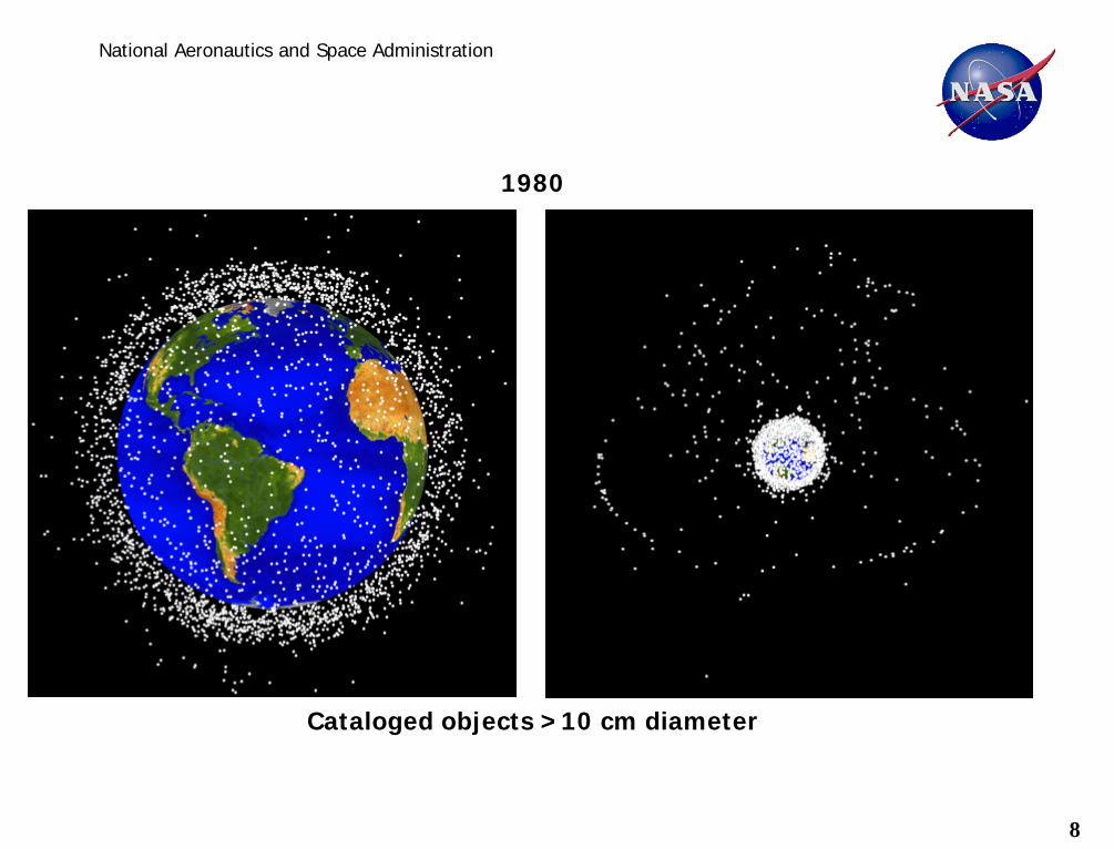
Cataloged objects >10 cm diameter
1960
6

National Aeronautics and Space Administration
Cataloged objects >10 cm diameter
1970
7
National Aeronautics and Space Administration
Cataloged objects >10 cm diameter
1980
8

National Aeronautics and Space Administration
Cataloged objects >10 cm diameter
1990
9

National Aeronautics and Space Administration
Cataloged objects >10 cm diameter
2000
10

National Aeronautics and Space Administration
Cataloged objects >10 cm diameter
2010
11

National Aeronautics and Space Administration
12
Debris movies
• Debris fly-through • Iridium-Cosmos collision

National Aeronautics and Space Administration
13
Orbital Debris Material Distributions - ISS

National Aeronautics and Space Administration
14
Growth of the Cataloged Populations
0100020003000400050006000700080009000
1000011000120001300014000150001600017000
1957
1959
1961
1963
1965
1967
1969
1971
1973
1975
1977
1979
1981
1983
1985
1987
1989
1991
1993
1995
1997
1999
2001
2003
2005
2007
2009
2011
2013
Num
ber o
f Obj
ects
Year
Monthly Number of Objects in Earth Orbit by Object Type
Total Objects
Fragmentation Debris
Spacecraft
Mission-related Debris
Rocket Bodies
FY-1C ASAT Test
Iridium-Cosmos
~1100 are operational

National Aeronautics and Space Administration
15
0
1
2
3
4
5
6
719
5719
5919
6119
6319
6519
6719
6919
7119
7319
7519
7719
7919
8119
8319
8519
8719
8919
9119
9319
9519
9719
9920
0120
0320
0520
0720
0920
1120
13
Mas
s in
Orb
it (m
illio
ns o
f kg)
Year
Monthly Mass of Objects in Earth Orbit by Object Type
Total Objects
Spacecraft
Rocket Bodies
Fragmentation Debris
Mission-related Debris
Mass in Space
No sign of slowing down!

National Aeronautics and Space Administration
16
Long-Term Projection & the Kessler Syndrome
“The current debris population in the LEO region has reached the point where the environment is unstable and collisions will become the most dominant debris-generating mechanism in the future” – Liou and Johnson, Science, 20 January 2006
0
5,000
10,000
15,000
20,000
25,000
30,000
35,000
1950 1970 1990 2010 2030 2050 2070 2090 2110
Effe
ctive
Num
ber o
f Obj
ects
in LE
O
Year
Non-Mitigation, objects ≥10 cm, with 1-σ
With space launches at recent rates

National Aeronautics and Space Administration
17
Agenda
• Micrometeoroid and orbital debris (MMOD) environment overview • Hypervelocity impact effects & MMOD shielding • MMOD risk assessment process • Requirements & protection techniques
– ISS – Shuttle – Orion/Commercial Crew Vehicles
• MMOD effects on spacecraft systems & improving MMOD protection – Radiators
• Coatings – Thermal protection system (TPS) for atmospheric entry vehicles
• Coatings – Windows – Solar arrays – Solar array masts – EVA Handrails – Thermal Blankets

National Aeronautics and Space Administration
18
Hypervelocity impact effects
• Even small MMOD impacts can cause a lot of damage – Hypervelocity MMOD impacts represent a substantial threat to spacecraft – Rule of thumb: at 7km/s, aluminum sphere can penetrate completely through an
aluminum plate 4x the sphere’s diameter – A multi-layer spaced shield provides more effective protection from hypervelocity impact
than single layer
Comparison of size of projectile to size of impact crater
Damage from a 1.3cm diameter sphere at 7km/s

National Aeronautics and Space Administration
19
MMOD Shielding
• Several types of shielding applied to spacecraft MMOD protection – Whipple shields – Nextel/Kevlar “Stuffed Whipple” shields – Multi-Shock shields
• Protection performance characterized by impact tests, simulations – Defined by “ballistic limit” equations (BLEs)
Al bumper
Al rear wall
standoff
WHIPPLE
Al bumper
Al rear wall
standoff Nextel/Kevlar
Stuffed Whipple
Nextel ceramic cloth
Kevlar fabric
Nextel bumpers
Kevlar rear wall
standoff
Flexible Multi-Shock

National Aeronautics and Space Administration
20
Monolithic versus Stuffed Whipple Shield Weight Comparison of Equal-Performance Shielding
Scale: 1” = 1”
Aluminum “Monolith” Shield 29.1 pounds per square foot
Stuffed Whipple Shield 4.5 pounds per square foot
2.00
” (s
olid
)
0.08” aluminum
thermal insulation
6 layers Nextel® AF-62
6 layers Kevlar® Style 710 (or KM2-705)
0.188” aluminum
(vacuum)
(vacuum)
(vacuum)
(spacecraft interior)
(spacecraft exterior)
(spacecraft interior)
(spacecraft exterior)
4.50”
0.5” diameter
aluminum sphere (debris simulant)
0.5” diameter
aluminum sphere (debris simulant)
Impact Velocity (7 km/s)
Impact Velocity (7 km/s)
equal performance
84% weight
reduction
2.00” aluminum
These shields can stop a 0.5” diameter aluminum debris projectile impacting at 7km/s, but the Stuffed Whipple shield weighs 84% less (94% if rear wall is excluded)
and costs much less to launch to orbit

National Aeronautics and Space Administration
21
MMOD shielding background
• MMOD shields typical composed of bumper(s), standoff, and rear wall (final protection layer)
– Exclude multi-layer insulation (MLI) thermal blanket
Shield
bumper
intermediate bumper
rear wall
Sta
ndof
f
Purpose: Breakup MMOD particle, laterally disperse resulting debris Key material & physical parameters (V ≥ 7 km/s): density, thickness to projectile diameter ratio, thermal properties
MMOD particle (projectile)
Purpose: Further breakup debris from first impact, slow expansion of debris cloud Key material & physical parameters (V ≥ 7 km/s): combination of first bumper and rear wall properties
Purpose: Stop debris from MMOD & bumper(s) Key material & physical parameters (V ≥ 7 km/s): strength, toughness, thickness

22
National Aeronautics and Space Administration

National Aeronautics and Space Administration
23
0
0.1
0.2
0.3
0.4
0.5
0.6
0.7
0.8
0 2 4 6 8 10 12 14Velocity (km/s)
Crit
ical
Al D
iam
eter
(cm
Whipple dcrit @ 0 degmonolithic dcrit @ 0 deg
Ballistic Regime Fragmentation &
Partial Melt Regime Complete Melt Regime Velocity Range:
State of Debris Cloud: (for Al on Al impacts)
Few solid fragments
Many (increasing with velocity) solid fragments & liquid
droplets
Fine droplets, few solid fragments, some vapor
Ballistic Limit Improvement due to Shield Standoff
∆ dCrit
Expect “failure” above curves
0.12cm Al bumper
0.32cm Al6061T6 rear wall
10cm
standoff
WHIPPLE
Ballistic Limits for Whipple Shield & equal mass Monolithic
23

National Aeronautics and Space Administration
24
ISS shielding overview
• Several hundred MMOD shields protect ISS, differing by materials, standoff distance, and capability
• Heavier shields on front & sides (where we expect most MMOD impacts), less capable shielding on aft, nadir and visiting vehicles
Earth
velocity direction
Russian Segment
NASA JAXA
ESA
colors represent different MMOD shield configurations
JAXA
Finite Element model (FEM) used in ISS MMOD risk assessments

National Aeronautics and Space Administration
25
MMOD directionality
• The Long-Duration Exposure Facility (LDEF) [1984-1990] provided the first detailed assessment of small particle debris in low Earth orbit
– LDEF maintained its orientation relative to the velocity vector, Earth/Space for its entire mission
• Over 30,000 observable MMOD strikes were identified on the exterior of LDEF (damage diameter ≥ 0.3mm)
• Of these MMOD impacts, approximately 20x more impacts were found on the forward face relative to the aft face, and 200x more on the forward than Earth

National Aeronautics and Space Administration
26
ISS “Stuffed Whipple” Shielding
• US, JAXA and ESA employ “Stuffed Whipple” shielding on the areas of their modules exposed to greatest amount of orbital debris & meteoroids impacts
• Nextel and Kevlar materials used in the intermediate bumper • shielding capable of defeating 1.3cm diameter aluminum sphere at 7 km/s, normal impact
NASA configuration JAXA configuration ESA configuration
2mm Al
MLI
6 Nextel AF62
6 Kevlar fabric
4.8mm Al
11.4
cm
1.3mm Al
MLI
3 Nextel AF62
4 Kevlar fabric
4.8mm Al
11.4
cm
2.5mm Al
MLI
4 Nextel AF62
Kevlar-Epoxy
4.8mm Al
13 c
m
Al Mesh
(Typical Configurations Illustrated)
Typically, bumpers are Al 6061-T6, rear walls are Al 2219-T87 or Al 2219-T851 Kevlar 29 style 710 or Kevlar KM2 style 705 fabric are typically used

National Aeronautics and Space Administration
27
Shielding materials
• Nextel (3M Inc. trade mark): fabric consisting of alumina-boria-silica ceramic fibers
– Other ceramic and glass fabrics tested, and will provide adequate MMOD protection (substitute equal mass for Nextel)
• Kevlar aramid fabric: highest hypervelocity protection performance found using Kevlar KM2 fabrics
– Other high-strength to weight materials incorporated in MMOD shields include Spectra, Vectran, carbon fabric and carbon-composites

National Aeronautics and Space Administration
28
FGB and Service Module (SM) Mesh & Multi-Shock MMOD Shields
• Majority of FGB shields include 2 or more bumpers spaced in front of the module pressure shell or propellant tank wall (superior to single bumper shields)
• Metal mesh layers provide additional protection in many FGB shields (a mesh causes greater spread to the debris cloud resulting from high velocity collision)
• SM augmentation shields rely on multi-shock ceramic fabric layers
• FGB shields & SM augmentation shields provide protection from 1-1.5cm diameter aluminum projectiles (typical).
• Unaugmented SM shields protect from ~0.3cm aluminum projectiles (typical)
FGB Zone 11c,d,f SM deployable shield/zone 6 orientation of zone 8 not parallel to 4 augmentation bumpers
0.3/10/1.5mm Al honeycomb
MLI steel mesh (2) fabric (1)
1.4mm Al pressure shell
10 c
m
MLI
basalt fabric layers
Original Zone 6 1.0mm Al
25 c
m
0.3/10/1.0mm Al honeycomb
1.6mm Al pressure shell
5 cm
va
riabl
e
SM conformal shield/zone 8
Original Zone 8 MLI
0.5/10/0.5mm graphite-epoxy honeycomb
2.3mm Al pressure shell
2 cm
1mm Al Corrugated 0.5mm Al
Russian “Kevlar” fabric (6) 10 c
m
Fiberglass panel

National Aeronautics and Space Administration
29
ISS Service Module Shielding • Service Module (SM) identified as high
penetration risk using Bumper risk analysis – large cone region – forward sides of small diameter cylinder
• Shields designed and tested, EVA installed – 23 augmentation shields for the cone region – 5 augmentation shields for the cylinder region
• 28 shields reduced SM MMOD risk by 30% Original Zone 8 MLI Thermal Blanket
0.5/10/0.5mm graphite-epoxy honeycomb
2mm Al pressure shell
2 cm
1mm Al Corrugated 0.5mm Al
Russian “Kevlar” fabric (6) 10 c
m
3mm Fiberglass panel
EVA Installation 23 “conformal” panels on cone region 5 panels on small diameter cylinder
SM “conformal” augmentation shield

National Aeronautics and Space Administration
30
Docking Compartment (DC) MMOD Shield & Performance Capability
Typical DC Shield (Whipple shield with MLI thermal blankets)
BUMPER Code Finite Element Model
0
0.1
0.2
0.3
0.4
0.5
0.6
0.7
0.8
0 5 10 15
Velocity (km/s)
Cri
tical
Al P
roj.
Dia
met
er (c
m)
dc @ 0dc @ 45dc @ 60data @ 0data @ 45data @ 60
DC-1 Ballistic Limit Equations (BLEs) and HVI Test Data
Shield Failure expected above curves Open symbols = no-failure data
Closed symbols = shield failure data
0.1cm Aluminum AMG6 bumper
MLI
1.7cm
0.4cm Aluminum AMG6 pressure shell
MLI
Ballistic Limit of shield (typical): 0.35cm Al projectile @ 7km/s, 0o
DC

National Aeronautics and Space Administration
31
Foam sandwich MMOD shielding
• Honeycomb core sandwich structures are used extensively on spacecraft • Honeycomb core tends to “channel” debris cloud and results in a
relatively poor MMOD shield • Replacing the honeycomb core with a metallic or ceramic foam provides
improved MMOD protection

National Aeronautics and Space Administration
32
Foam sandwich hypervelocity test 3.6mm diameter Al2017T4 sphere at 6.2-6.8 km/s, 0-
deg

National Aeronautics and Space Administration
33
Smart MMOD shields
• Implementing impact damage detection/location sensors is a high-priority – Successfully added wireless accelerometer sensor detection system to Shuttle to
monitor ascent and MMOD impacts on wing leading edge – Other methods to detect/locate impact damage available based on sensors to detect:
acoustic emissions, fiber-optic & electrical grids, piezoelectric PVDF film, impact flash, radiofrequency emissions
– Working to implement/integrate impact sensors into MMOD protection shields on next generation spacecraft
Test article (2’x2’) with integrated sensors & piezoelectric sensor array
4 channel DIDS
1.7” x 1.7” x 0.8”
Distributed impact detection system (DIDS)

National Aeronautics and Space Administration
34
Shielding Summary
• MMOD shielding capability influenced by both: 1. Configuration – “standoff” (more is better), number of bumper shield layers 2. Material selection – ceramics/metals on exterior of shield, high-strength to weight ratio
(fabrics & composites) on interior of shield
• More information available (including many BLEs): – NASA TP-2003-210788, Meteoroid/Debris Shielding – NASA TM-2009-214785, Handbook for Designing MMOD Protection – NASA TM-2003-212065, Integration of MMOD Impact Protection Strategies into
Conceptual Spacecraft Design – NASA TM-2009-214789, MMOD Shield Ballistic Limit Analysis Program – NASA/TM-2014-218268, Volume I & II, Micrometeoroid and Orbital Debris (MMOD)
Design and Analysis Improvements, NASA Engineering and Safety Center Report NESC-RP-12-00780
– E.L. Christiansen and J.H. Kerr, Ballistic Limit Equations for Spacecraft Shielding, International Journal of Impact Engineering, Vol. 26, pp. 93-104, 2001

National Aeronautics and Space Administration
35
Agenda
• Micrometeoroid and orbital debris (MMOD) environment overview • Hypervelocity impact effects & MMOD shielding • MMOD risk assessment process • Requirements & protection techniques
– ISS – Shuttle – Orion/Commercial Crew Vehicles
• MMOD effects on spacecraft systems & improving MMOD protection – Radiators
• Coatings – Thermal protection system (TPS) for atmospheric entry vehicles
• Coatings – Windows – Solar arrays – Solar array masts – EVA Handrails – Thermal Blankets

National Aeronautics and Space Administration
36
MMOD Risk Assessment Process
• Process used to identify MMOD risk drivers, evaluate risk mitigation options & optimization, verify compliance with protection requirements

National Aeronautics and Space Administration
37
ISS Finite Element Model for MMOD risk assessment Block 7 (2017-2028)
PMM relocated to N3f, add BEAM, IDA-1 & IDA2
Progress @ MRM2 Progress @ SM
Soyuz @ NM Soyuz @ MRM1
Each color represents a different shield type
37

National Aeronautics and Space Administration
38
Failure criteria
• Failure criteria required for each zone of spacecraft that clearly defines the limits of allowable damage (or failure threshold)
– Basis of impact tests/analysis, ballistic limit equations, risk assessments • Typically defined by Engineering & Program/Project (not by MMOD) • ISS crew module pressure shell
– Typically failure is defined as detached spall or through-hole of pressure shell
– Loss-of-crew (LOC) assessments for ISS include analysis of internal effects of penetrations, with criteria established for LOC due to fatal crew injury, hypoxia, fragmentation/explosion of pressure vessels (internal and external), and several other failure modes
Damage Class C3: Detached spall Damage Class C4: Perforation

National Aeronautics and Space Administration
39
Failure criteria (cont.)
• Reentry vehicles, crew return vehicles – Loss-of-crew (LOC) failure include: (a) pressure vessel puncture and/or rupture
leading to immediate on-orbit loss-of-vehicle/crew, (b) damage to thermal protection system (TPS) leading to loss-of-vehicle during reentry
– Loss-of-mission (LOM) failure includes: (a) radiator/coolant leaks, (b) others

National Aeronautics and Space Administration
40
Hypervelocity Impact Test Results Anchor Analysis
• JSC-KX plans and performs over 400 impact tests per year – Primarily WSTF two-stage light gas-guns up to 8 km/s – University of Dayton Research Institute 3-stage launcher to 10 km/s – Southwest Research Institute shaped-charge launcher to 11 km/s
• Data used to develop and verify ballistic limit equations used in Bumper code on range of different spacecraft components and subsystems
National Aeronautics and Space Administration
41
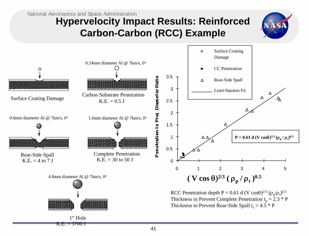
Surface Coating Damage Carbon Substrate Penetration
Rear-Side Spall Complete Penetration
K.E. = 0.5 J
K.E. = 4 to 7 J K.E. = 30 to 50 J
P = 0.61 d (V cosθ)2/3 (ρp / ρt)0.5
( V cos θ)2/3 ( ρp / ρt )0.5
0
0.5
1
1.5
2
2.5
3
3.5
0 1 2 3 4 5
Surface Coating Damage
CC Penetration
Rear-Side Spall
Least-Squares Fit
RCC Penetration depth P = 0.61 d (V cosθ)2/3 (ρp/ρt)0.5 Thickness to Prevent Complete Penetration tp = 2.3 * P Thickness to Prevent Rear-Side Spall ts = 4.5 * P
0.24mm diameter Al @ 7km/s, 0o
0.6mm diameter Al @ 7km/s, 0o 1.0mm diameter Al @ 7km/s, 0o
1” Hole K.E. = 3700 J
4.8mm diameter Al @ 7km/s, 0o
Hypervelocity Impact Results: Reinforced Carbon-Carbon (RCC) Example

National Aeronautics and Space Administration
42
MMOD Risk Assessment Tools
• Bumper Code – Perform penetration & damage risk assessments • MSC-Surv – Assess consequences of penetration for ISS: loss-of-crew,
evacuation risk • Hydrocodes (CTH, Exos, others) – Numerical simulation of hypervelocity
impact (virtual test shots) Bumper Code CTH Code

National Aeronautics and Space Administration
43
Analysis Products
• Ballistic limit equations, damage equations • Risk quantification:
– Spacecraft damage and/or loss – Penetration of pressure shell – air leak – Crew evacuation – Loss of crew – Uncertainties
• Requirements verification • Risk drivers – what area of vehicle controls
risk, focus of more analysis and/or shielding modifications
• Assess operational methods to control risk: – Flight attitude, altitude – Dock location, orientation – Thermal protection system (TPS)
inspection/damage mitigation
ISS Soyuz Penetration Risk Color Contour Red=high risk, Blue=low risk

National Aeronautics and Space Administration
44
Post Flight MMOD Inspection: STS-130 Number of MMOD impacts Largest MMOD impacts
Windows 15 craters W1, 4.2 x 3.6 mm
6 R&R’s (W1,2,6,7,8 & 11)
Radiators 25 MMOD damages reported 1 face sheet perforation
Wing leading edge & nose cap
9 MMOD indications (reviewed by LESS PRT)
Panel 18R, 3.2 x 2.8 mm, max depth = 0.46 mm no exposed substrate
MMOD impact on W1 1 mm 1 mm MMOD impact on Panel 18R MMOD impact on Panel LH3 1 mm

National Aeronautics and Space Administration
45
Post Flight MMOD Inspection: ISS
MPLM Pump Module (PM)
PM Adapter Plate Crater in PM handrail

National Aeronautics and Space Administration
46
Agenda
• Micrometeoroid and orbital debris (MMOD) environment overview • Hypervelocity impact effects & MMOD shielding • MMOD risk assessment process • Requirements & protection techniques
– ISS – Shuttle – Orion/Commercial Crew Vehicles
• MMOD effects on spacecraft systems & improving MMOD protection – Radiators
• Coatings – Thermal protection system (TPS) for atmospheric entry vehicles
• Coatings – Windows – Solar arrays – Solar array masts – EVA Handrails – Thermal Blankets

National Aeronautics and Space Administration
47
International Space Station (ISS) MMOD Requirements
• MMOD requirements are key aspect of providing adequate MMOD protection
• ISS MMOD requirement (SSP 41000): 0.76 probability of no penetration
(PNP) or better over 10 years – No more than 24% penetration risk allowed over 10years for all MMOD critical items
which include crew modules and external stored energy devices (pressure vessels & control moment gyros)
• No more than 0.8% penetration risk allowed on average over 10years per MMOD critical item
• Loss-of-crew and crew evacuation risk assessments performed for input into ISS Probabilistic Risk Assessment (PRA)
– Risk informed decisions based on PRA
• Requirements for functional equipment set on case-by-case basis (functional = failure does not lead to loss-of-crew)

National Aeronautics and Space Administration
48
ISS MMOD protection approach
• Multi-faceted approach to mitigating MMOD Risk on ISS 1. Robust shielding – ISS has best shielding ever flown: US/ESA/Japan
Nextel/Kevlar “stuffed” Whipple shields effective for 1.3cm diameter debris impacting at typical impact conditions
– Augmentation shields added by extravehicular activity (EVA) to Russian Service Module
– Upgrades to Soyuz and Progress MMOD protection – Redundant & hardened external systems; e.g. US Radiators
2. Collision avoidance – Maneuver to avoid ground-trackable orbital debris (typically ≥
10cm diameter)
3. Sensors & crew response to leak if needed – Leak detection, isolation, repair
2mm Al
MLI
6 Nextel AF62
6 Kevlar
4.8mm Al
11.4
cm
0.5” diameter hypervelocity projectile penetrates nearly 2” thick aluminum block, but is stopped by NASA stuffed Whipple shields which weigh far less (same as 3/8” thick aluminum)

National Aeronautics and Space Administration
49
Visiting Vehicle Requirements
• Shuttle MMOD requirements were two fold: – Loss-of-crew (LOC) risk should not exceed 1 in 200 per mission
• Driving loss-mode for LOC was MMOD damage to thermal protection system (TPS) materials leading to loss-of-vehicle during reentry
– Loss-of-mission (LOM) due to radiator tube leaks should not exceed 1 in 61 per mission
• ISS commercial crew transport vehicle MMOD requirements:
– Penetration risk causing crew-module leak &/or tank failure while docked to ISS should not exceed 1-0.99999^(surface area_m2 * duration_years)
– MMOD LOC/LOM requirements are derived from overall vehicle LOC/LOM requirements, and cover the risk to TPS & loss of vehicle during reentry
National Aeronautics and Space Administration
50
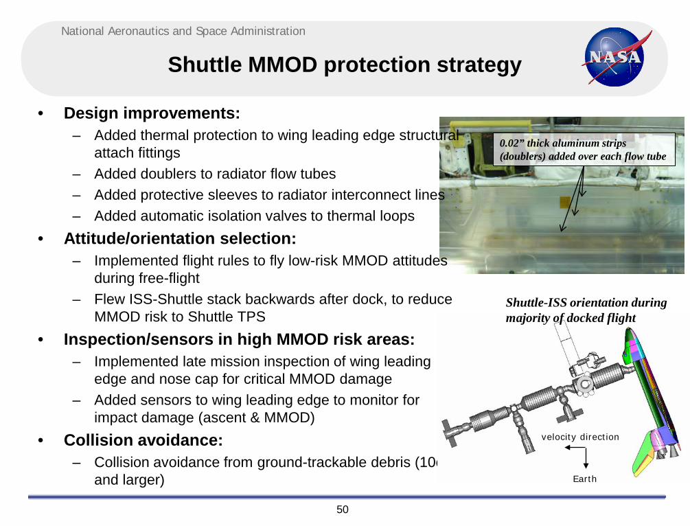
Shuttle MMOD protection strategy
• Design improvements: – Added thermal protection to wing leading edge structural
attach fittings – Added doublers to radiator flow tubes – Added protective sleeves to radiator interconnect lines – Added automatic isolation valves to thermal loops
• Attitude/orientation selection: – Implemented flight rules to fly low-risk MMOD attitudes
during free-flight – Flew ISS-Shuttle stack backwards after dock, to reduce
MMOD risk to Shuttle TPS • Inspection/sensors in high MMOD risk areas:
– Implemented late mission inspection of wing leading edge and nose cap for critical MMOD damage
– Added sensors to wing leading edge to monitor for impact damage (ascent & MMOD)
• Collision avoidance: – Collision avoidance from ground-trackable debris (10cm
and larger)
velocity direction
Shuttle-ISS orientation during majority of docked flight
Earth
0.02” thick aluminum strips (doublers) added over each flow tube

National Aeronautics and Space Administration
51
Agenda
• Micrometeoroid and orbital debris (MMOD) environment overview • Hypervelocity impact effects & MMOD shielding • MMOD risk assessment process • Requirements & protection techniques
– ISS – Shuttle – Orion/Commercial Crew Vehicles
• MMOD effects on spacecraft systems & improving MMOD protection – Radiators
• Coatings – Thermal protection system (TPS) for atmospheric entry vehicles
• Coatings – Windows – Solar arrays – Solar array masts – EVA Handrails – Thermal Blankets

National Aeronautics and Space Administration
52
MMOD Considerations for Radiators
• Radiator flow loops are subject to penetration by MMOD – Radiators are large and will be impacted by MMOD during each flight – Radiator flow tube area is smaller, but still experiences MMOD damage – Leaks can result in degraded spacecraft function and early mission termination – Radiator flow paths can be hardened to reduce the risk of leaks from MMOD damage – Radiator interconnect lines also subject to MMOD failure, and can be hardened from
damage by increasing thermal insulation, adding beta-cloth sleeves, thicker walls, increasing flexible braiding, or wrapping with Nextel/Kevlar
• Radiator coatings typically either spall or delaminate around impact site – Silver-teflon (Shuttle radiator panels) delaminate – Z93 paint (ISS radiator panels) spall – Diameter of spall/delamination typically large compared to impactor diameter (4-15x),
but area covered by spall/delamination small relative to radiator area, even for long-duration missions (a few percent of coating is damaged over 10-30year ISS missions), therefore not likely to result in major thermal issue

National Aeronautics and Space Administration
53
Radiator coating damage typical hypervelocity impact test results
HITF-07428 0.4mm Al
7.01 km/s @ 0° Delamination to Proj. diameter
ratio = 12
Silver-Teflon tape Z-93 paint
HITF-07447 2.0mm Al
6.95 km/s @ 0° Paint spall to Proj. diameter
ratio = 3.5
National Aeronautics and Space Administration
54
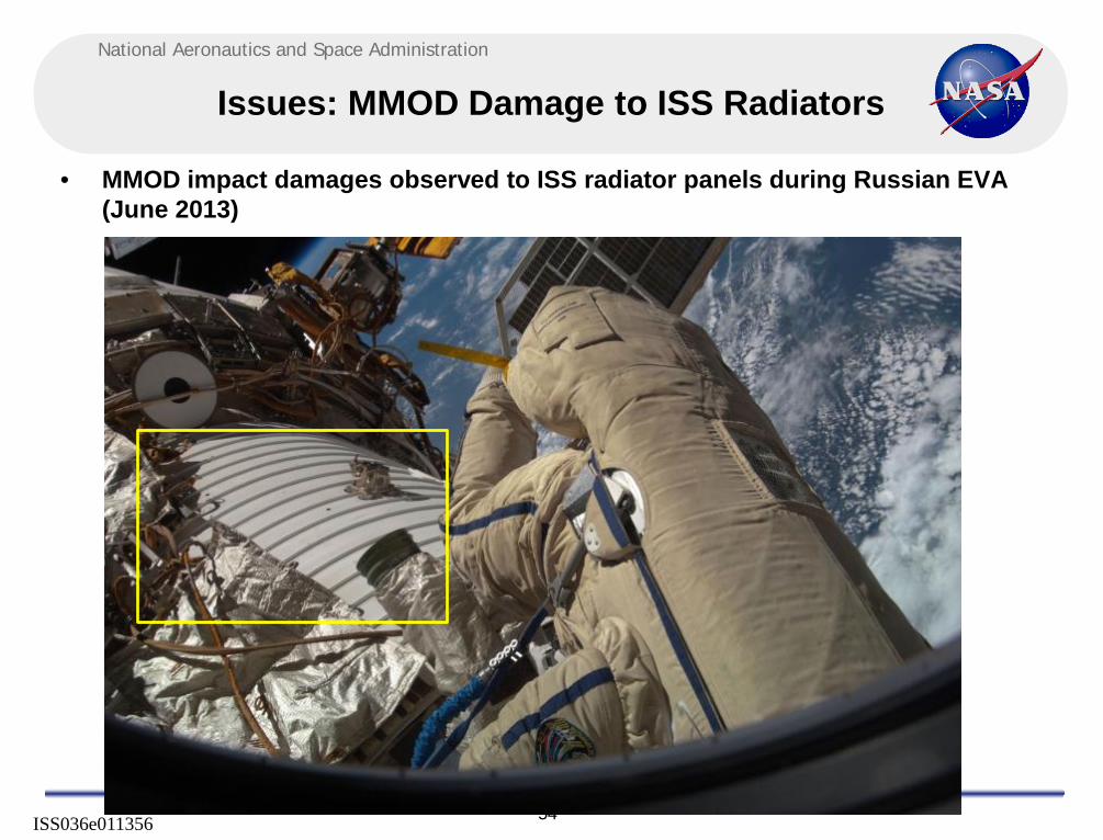
Issues: MMOD Damage to ISS Radiators
• MMOD impact damages observed to ISS radiator panels during Russian EVA (June 2013)
ISS036e011356

National Aeronautics and Space Administration
55
MMOD Damage to ISS Radiators
ISS036e011356

National Aeronautics and Space Administration
56
MMOD Damage to ISS
• MMOD impact damages observed to radiator panel during EVA-20 (Nov. 2012)
ISS033e017859
P6 Photovoltaic Radiator Torque Panel (NOTE: numerous smaller impacts not indicated)

National Aeronautics and Space Administration
57
MMOD Damage to ISS Radiators (US)
• MMOD impact damages observed to ISS radiator panels (Aug. 2013)
ISS036e037365

National Aeronautics and Space Administration
58
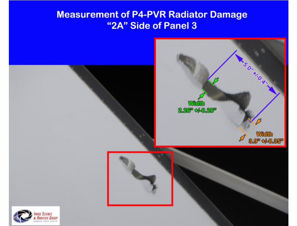
P4 photovoltaic radiator
• Initial indication found on 6/30/2014
National Aeronautics and Space Administration
59

National Aeronautics and Space Administration
60
ISS PVR Panel Construction
• 124” x 70” x 0.69” thick panel • Aluminum face sheet
– Z93 white paint • Aluminum flow tube housing extrusion
with Inconel flow tube – Evenly spaced 2.6 inches except
outermost tube spaced 3.5 inches • Note, flow tube relatively thick wall
(>0.05”) and in well protected location at center of panel

National Aeronautics and Space Administration
61
Shuttle Radiator Panels
• Shuttle radiator flow tubes are located directly below facesheet and are relatively thin-walled (0.02” thick)
• Shuttle flow tubes are more vulnerable than ISS radiators to MMOD failure
Al Doubler (0.02” thick x 0.4” W)
0.005” Silver-Teflon Type VI Tape
F21 Tube
FWD Radiator (Typ.) 34 x 0.187” OD Tubes/Side 15.1 ft x 10.5 ft Panel 4 Panels/Vehicle
0.011” Facesheet 3/16” Cell 3.1 Pcf Al Core
0.9”
0.5”
1.9”
AFT Radiator (Typ.) 26 x 0.236” OD Tubes/Panel 15.1 ft x 10.5 ft Panel 4 Panels/Vehicle
0.005” Silver-Teflon Type IV Tape
F21 Tube
BEFORE MOD AFTER MOD
0.011” Facesheet
• Aluminum doublers adhesively bonded to Shuttle radiator facesheets over each flow tube to improve MMOD penetration resistance & decrease leak risk
• Completed modification in 1999-2000 across Orbiter fleet

National Aeronautics and Space Administration
62
STS-128 Shuttle Radiator Impact shows why adding protection to vulnerable areas of
spacecraft is a good thing
Image of MMOD impact into LH1 Radiator doubler protecting flow-
tubes Crater diameter in Al doubler = 0.8 mm Crater depth = 0.58 mm Doubler thickness = 0.51 mm
Simulation of impact after 2 micro-seconds with doubler: crater through thermal tape (green) and penetration nearly through doubler (red)…i.e., similar to actual damage.
Simulation of same impact after 2 micro-seconds without doubler: crater through thermal tape (green), through facesheet (yellow) and through flow tube wall (blue)…i.e., leak would have occurred without doubler.
• During STS-128, an impact occurred on center-line of a radiator doubler, which protects the Shuttle radiator flow tubes from MMOD
– Impact crater penetrated through the thermal tape, completely through the 0.02” thick doubler, and damaged the facesheet below the doubler
– Analysis indicates this impact would have penetrated the flow tube if the doublers were not present – Doublers added in 1997-1999 time period, to provide additional protection for ISS missions – Conclusion: Doublers performed as designed, preventing a radiator tube puncture

National Aeronautics and Space Administration
63
Radiator Hypervelocity Impact References
• J. Hyde, E. Christiansen, D. Lear, J. Herrin, Recent Shuttle Post-Flight MMOD Inspection Highlights, IAC-10.A6.3.1, presented at the 61st International Astronautical Congress, Prague, CZ, 2010
• J.L. Hyde, E.L. Christiansen, D.M. Lear, J.H. Kerr, Micrometeoroid and Orbital Debris Threat Mitigation Techniques for the Space Shuttle Orbiter, Fifth European Conference on Space Debris, 2009
• D. Lear, E. Christiansen, J. Hyde, J. Herrin, F. Lyons, J. Kerr, S. Ryan, Investigation of Shuttle Radiator Micro-Meteoroid & Orbital Debris Damage, AIAA 2009-2361, 50th AIAA/ASME/ASCE/AHS/ASC Structures, Structural Dynamics, and Materials Conference, 4 - 7 May 2009, Palm Springs, California, 2009
• NASA JSC-66365, Radiator Hypervelocity Impact (HVI) Crater Characterization Study Test Program, Phase – 2, 2012 • NASA JSC-66366, Radiator Hypervelocity Impact (HVI) Crater Characterization Study Test Program, Phase – 1, 2012 • NASA JSC-28524, Hypervelocity impact testing of betacloth covers on Orbiter radiator external lines, 2001 • E.L. Christiansen, R. Bernhard, and N. Hartsough, Orbiter Meteoroid/Orbital Debris Impacts: STS-50 (6/92) through STS-86 (10/97),
NASA JSC-28033, August 1998 • E.L. Christiansen, J.L. Hyde, and R.P. Bernhard, Space Shuttle Debris and Meteoroid Impacts, Advances in Space Research, Vol. 34,
Issue 5, pp. 1097-1103, 2004, presented at World Space Congress, 2002 • J.P. Loftus, E. Christiansen, W.C. Schneider, and M. Hasselbeck, Shuttle Modifications for Station Support, IAF-97-IAF.I.3.08, 48th
International Astronautical Congress, October 6-10, 1997 • T.E. Jensen, S.E. Loyd, D.W. Whittle, E.L. Christiansen, Visible Effects of Space Debris on the Shuttle Program, IAA-97-IAA.6.4.02,
48th International Astronautical Congress, October 6-10, 1997 • E.L. Christiansen, R.P. Bernhard, J.L. Hyde, J.H. Kerr, K.S. Edelstein, J. Ortega, and J.L. Crews, Assessment of High Velocity
Impacts on Exposed Space Shuttle Surfaces, ESA Report on proceedings of the First European Conference on Space Debris, ESA SD-01, pp.447-452, April 5-7, 1993
• J.L. Rhatigan, E.L. Christiansen, and M.L. Fleming, On Protection of Freedom's Solar Dynamic Radiator From the Orbital Debris Environment: Part I - Preliminary Analysis and Testing, Journal of Solar Energy Engineering, Vol.114, p.135, August 1992
• J.L. Rhatigan, E.L.Christiansen, and M.L. Fleming, On Protection of Freedom's Solar Dynamic Radiator From the Orbital Debris Environment: Part II - Further Testing and Analysis, Journal of Solar Energy Engineering, Vol.114, p.142, August 1992
• J.L. Rhatigan, E.L. Christiansen, and M.L. Fleming, On Protection of Freedom Solar Dynamic Radiator from the Orbital Debris Environment: Part 2 – Further Testing and Analyses, NASA TM-104514, April 1992
• J.L. Rhatigan, E.L. Christiansen, and M.L. Fleming, On Protection of Freedom Solar Dynamic Radiator from the Orbital Debris Environment: Part I - Preliminary Analysis and Testing, NASA TM-102458, April 1990
National Aeronautics and Space Administration
64
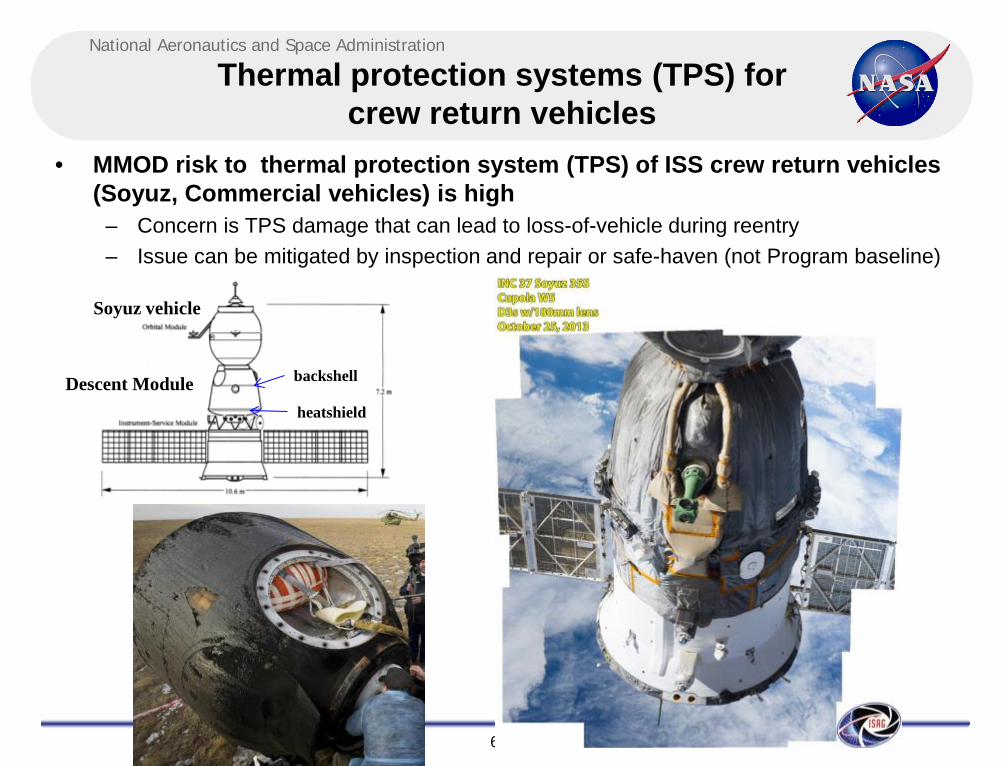
Thermal protection systems (TPS) for crew return vehicles
• MMOD risk to thermal protection system (TPS) of ISS crew return vehicles (Soyuz, Commercial vehicles) is high
– Concern is TPS damage that can lead to loss-of-vehicle during reentry – Issue can be mitigated by inspection and repair or safe-haven (not Program baseline)
Soyuz vehicle
backshell
heatshield
Descent Module

National Aeronautics and Space Administration
65
Thermal protection systems (TPS) for crew return vehicles (cont.)
• TPS example: Low-density ceramic tiles cover backshell of Orion crew module
• Impact penetrations into TPS that extend to bondline with substrate are limits of allowable damage
Backshell tile • Typical hypervelocity
damage: craters with “fingers” of higher density debris that extend beyond crater boundary
• Inspection and or sensors could be used to find critical damage before reentry
• TPS repair or rescue flight needed if critical damage found in inspection

National Aeronautics and Space Administration
66
Typical Thermal Protection System (TPS) Tile Impact Damage
Tile Test HITF-7469 projectile: 2.4mm (3/32”) diameter Al 2017T4, 7.00 km/s, 0o impact angle
Side view
Top view

National Aeronautics and Space Administration
67
CT Scans of Tile Damage
2 1
1 2
3

National Aeronautics and Space Administration
68
TPS Coating Damage
• Coatings on TPS can be important in reentry survivability • Example: Si-C coating on Reinforced Carbon-Carbon of Shuttle wing-
leading edge and nose cap • Coating damage was considered limits of acceptable damage for “hot”
areas of wing leading edge and nose cap based on results of hypervelocity impact tests and arc-jet tests, as well as thermal analysis
1.00” Ø hole 4.89mm
0.50” Ø hole 2.75mm
0.25” Ø hole 1.68mm
0.12” - 0.99” Ø hole 1.10-4.84mm
0.25” Ø exposed substrate (Test 6) 0.81mm
0.19” Ø exposed substrate (Test 11) 0.69mm
0.14” Ø exposed substrate (Test 5) 0.58mm
0.09” Ø exposed substrate (Test 4) 0.47mm
Failure Criteria
Critical Orbital Debris Ø
(7km/s & 0°)

National Aeronautics and Space Administration
69
Pre-Arc-Jet Test A308-9 Model 2238 Exposed Substrate: 0.25” x 0.26”
Test Condition: 2700F/100 psf FAILED WITH SMALL BREACH (0.125”)
RCC Failure Criteria “Test 6” Model 2238 (Front)
Representative of
Projectile size
Post Arc-Jet Test (0.125” through-hole) Test Notes: No surface activity until 811 sec. Small hole developed but arrested by glass flow. Total test duration: 900 sec.

National Aeronautics and Space Administration
70
Window Damage & MMOD Protection
• Spacecraft windows typically are multiple panes of glass/transparent materials
– Thermal pane or debris pane – Redundant pressure panes (typical)
• MMOD impacts on fused-silica glass creates large diameter craters relative to impactor size
– Typical crater diameters 30-50x impactor diameter in HVI tests – Issue for pressure panes and for re-use of thermal panes (e.g. Shuttle)
• Window protection: – Thermal panes for reentry vehicles, debris panes for spacecraft, exterior of pressure
pane(s) – Shutters (ISS): US Lab window has single wall shutter, Cupola has multiwall shutters – Window materials
• Fused-silica: conventional window material for both thermal/debris panes and pressure panes, brittle, good optical qualities
• Polycarbonate (Hyzod): hatch window external cover • Acrylic: pressure pane alternative • Tempered glass (Chemcor): high-strength but very-low MMOD damage tolerance

National Aeronautics and Space Administration
71
Observed Spacecraft MMOD Impacts Shuttle Windows
Sampling of Shuttle Window MMOD Impact Craters (all displayed on same dimensional scale)

National Aeronautics and Space Administration
72
MMOD Impacts on Windows
Service Module Window 7 Impact ~7mm across outer crack features
STS-94 Window damage observed on-orbit 0.6mm deep, Al impactor
• Window ports are exposed to meteoroid/orbital debris impact – Over 1500 hypervelocity pits identified on Shuttle windows and ~130 of these large enough to
caused window replacement
STS-59 Side Hatch Window Damage
National Aeronautics and Space Administration
73
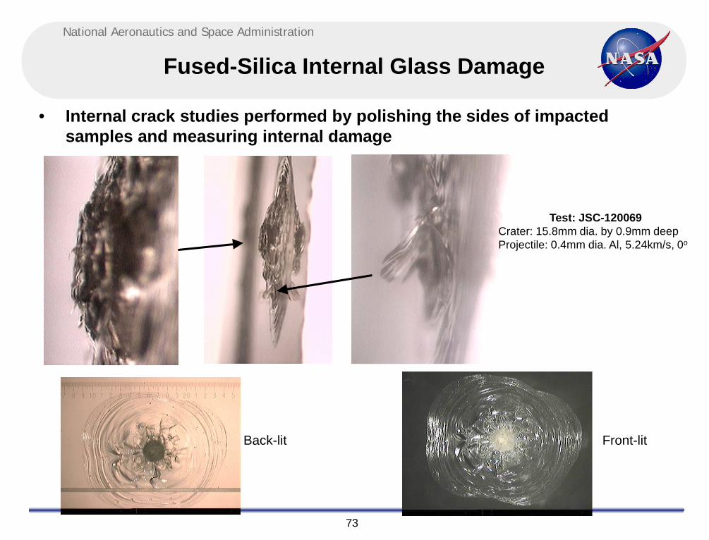
Fused-Silica Internal Glass Damage
• Internal crack studies performed by polishing the sides of impacted samples and measuring internal damage
Back-lit Front-lit
Test: JSC-120069 Crater: 15.8mm dia. by 0.9mm deep Projectile: 0.4mm dia. Al, 5.24km/s, 0o

National Aeronautics and Space Administration
74
Test Results (Unpressurized vs. Pressurized)
• Projectile Conditions: 0.8 mm diameter Al 2017T4, 6.9 km/s, 0o
Unpressurized – Glass Unstressed Pressurized – Glass Stressed
5cm 5cm

National Aeronautics and Space Administration
75
Cupola Shutters
• ISS Cupola have multi-layer Shutters that provide MMOD protection of the windows, when the shutters are closed
Al Shutter Hat (0.2cm)
Nextel AF62 (3 sheets) 10cm
Kevlar KM2 (14 sheets)
Debris Pane (t=0.37” overhead, 0.38” sides)
Redundant Pressure Pane (t=1.45” overhead, 1.00” sides)
Primary Pressure Pane (t=1.45” overhead, 1.00” sides)
Gap=2.5cm
10cm
2nd Al layer (0.127cm)
Al 6061 Catcher Plate (0.25cm)
1.3cm Al particle on Ballistic Limit @ 7km/s, 0o
National Aeronautics and Space Administration
76
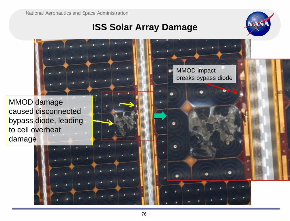
ISS Solar Array Damage
MMOD damage caused disconnected bypass diode, leading to cell overheat damage
MMOD impact breaks bypass diode

National Aeronautics and Space Administration
77
Solar Array Damage MMOD impact breaks bypass diode causing overheat
Front of Panel Back of Panel
MMOD hole
MMOD hole
iss040e064550 iss040e064597
Disconnected diode

National Aeronautics and Space Administration
78
ISS Solar Array Mast
• Deployable structural booms or masts used to support ISS solar arrays

National Aeronautics and Space Administration
79
MMOD Damage to ISS Solar Array Masts
• Elements of the solar array masts have been damaged from MMOD impacts • If critical damage to mast elements found during inspection, solar array will
need to be operated under restricted/protect flight rules
ISS038e006032, Nov. 2013

National Aeronautics and Space Administration
80
Hypervelocity impact tests
• Mast elements have been hypervelocity impact tested and structurally tested to assess residual strength for ISS life extension

National Aeronautics and Space Administration
81
Handrail and EVA tool MMOD damage
• Many craters noted to ISS handrails and EVA tools • Sharp crater lips have lead to cuts on EVA gloves • EVA terminated early on STS-118 due to glove cuts • Modifications to EVA suit and ISS EVA procedures necessary to reduce cut
glove risk from MMOD damage
Crater on ISS pump module handrail 1.85mm diameter x 0.8mm deep
Returned STS-135
Crater on D-handle tool 5mm diameter
Repaired on-orbit during STS-123 Tear in EVA glove (STS-118 EVA#3)

National Aeronautics and Space Administration
82
Thermal Blankets
• Thermal blankets are typically light-weight and easily penetrated by MMOD impacts
• Toughened thermal blankets incorporate additional MMOD layers to improve projectile breakup and stopping capability
– Additional data available in NASA/TM-2014-218268, Volume I & II, Micrometeoroid and Orbital Debris (MMOD) Design and Analysis Improvements, NASA Engineering and Safety Center Report NESC-RP-12-00780
Toughened thermal blankets with integrated impact sensor film
Impact Sensor Film
Impact tests

National Aeronautics and Space Administration
83
Concluding Remarks
• Highly effective MMOD shields have been developed & implemented on ISS and commercial vehicles
• Toughened radiator systems have been developed & implemented • Reentry vehicles are sensitive to MMOD damage and require combination of
improved design as well as operations (low-risk attitudes, on-orbit inspection) to reduce MMOD risk:
– Thermal protection systems – Windows – Radiators

National Aeronautics and Space Administration
84
BACKUP CHARTS

National Aeronautics and Space Administration
85
Progress CM Shielding 30deg impact data for Aluminum and Steel Projectiles
• Tests indicate approximately 2mm diameter aluminum projectile penetrates Progress CM shielding (creating hole in pressure shell), whereas 1mm diameter steel projectile penetrates Progress CM
– Aluminum used with ORDEM 2000, steel with ORDEM 3.0 – Risk increases substantially as MMOD penetration size decreases
85

National Aeronautics and Space Administration
86
Ku-band antenna
• An MMOD Strike was seen on the ISS Ku Antenna Gimbal Gear Cover. The image was captured during Mission ULF2 / STS-126.
• Interior damage?

National Aeronautics and Space Administration
87
STS-120 Solar Array Wing (SAW) EVA repair was caused by MMOD impact damage
During STS-120 two solar array wings were removed from Z1 truss and relocated to P6 location. During re-deployment, the 4B solar array wing was torn in two places, due to a snagged guide wire. The guide wire was removed and “cuff-links” added to stabilize the array.

National Aeronautics and Space Administration
88
Scanning Electron Microscope EDXA Evaluation of retrieved guide wire
7 of 21 wires in the guide wire cable were broken, causing the guide wire to hang-up in a solar array grommet. 3 of the 7 cut wires exhibited evidence of extensive melt at broken ends, indicative of MMOD impact.

National Aeronautics and Space Administration
89
ISS Service Module Shielding • Service Module (SM) identified as high
penetration risk using Bumper risk analysis – large cone region – forward sides of small diameter cylinder
• Shields designed and tested, EVA installed – 23 augmentation shields for the cone region – 5 augmentation shields for the cylinder region
• 28 shields reduced SM MMOD risk by 30%
High-risk (red) Low-risk (blue)
Original Zone 8 MLI Thermal Blanket 0.5/10/0.5mm graphite-epoxy
honeycomb 2mm Al pressure shell
2 cm
1mm Al Corrugated 0.5mm Al
Russian “Kevlar” fabric (6)
10 c
m
3mm Fiberglass panel
EVA Installation 23 “conformal” panels on cone region 5 panels on small diameter cylinder
SM “conformal” augmentation shield

National Aeronautics and Space Administration
90
HVIT Team: HVI Testing and MMOD Risk Assessments
Hypervelocity Impact Testing: • Objective: understand how a spacecraft surface and underlying structure “shield” responds to impact from an orbital debris or micrometeoroid
• Inputs: impact velocity (mostly 3-8 km/s), impact angle (usually 0o, 30o, 45o, 60o), projectile diameter (aluminum, nylon, ruby, steel) • Product: a ballistic limit equation (BLE) that calculates a critical particle diameter that will fail the shield as defined by the specific failure criteria
MMOD Risk Assessments: • Objective: use the Bumper risk assessment code to estimate the micrometeoroid and orbital debris (MMOD) risk to a spacecraft for a given set conditions.
• Bumper inputs: • spacecraft geometry • altitude, inclination, orientation • start year, exposure duration • debris or meteoroid • BLE and failure criteria
• Product: • MMOD risk results • Impact (NI, PNI, odds) • Penetration (NP, PNP, odds) • Color risk contours & VBETA

National Aeronautics and Space Administration
91
Hypervelocity Impact Testing
Testing at WSTF: • 3,500 HVI tests completed 2004-2011 • average 440 tests per year • testing performed on WSTF two-stage light gas guns (2SLGG)
• range selection driven by projectile size, test sample size, and budget •.17-cal, .50-cal, 1” ranges • turnaround times vary
JSC-KX Hypervelocity Impact Technology (HVIT) Team:
• develops test matrix • completes test readiness review • prepares (builds up) test samples • ships samples and projectiles to WSTF • daily coordination with WSTF • performs post test sample analysis • documents test series in report • develops ballistic limit equations

National Aeronautics and Space Administration
92
WSTF Remote Hypervelocity Test Laboratory (RHTL)

National Aeronautics and Space Administration
93
WSTF Remote Hypervelocity Test Laboratory (RHTL)

National Aeronautics and Space Administration
94
WSTF .17-cal range
.17-cal range: Projectiles: 0.10 to 3.6 mm diameter Velocity: 1.5 to 8.5 km/s Chamber: 3.5 ft diameter x 7 ft long

National Aeronautics and Space Administration
95
WSTF .50-cal range
.50-cal range: Projectiles: 0.40 to 11.51 mm diameter Velocity: 1.5 to 7.0 km/s Chamber: 5 ft diameter x 8 ft long

National Aeronautics and Space Administration
96
WSTF 1” range
1”range: Projectiles: 0.40 to 22 mm diameter Velocity: 1.5 to 7.0 km/s Chamber: 9 ft diameter x 30 ft long

National Aeronautics and Space Administration
97
.50-cal Test
Pretest photo Post Test Photo
Phantom camera impact video (67 kfps)

National Aeronautics and Space Administration
98
HVIT Team: MMOD Risk Assessments Bumper Code
Running Bumper interactively (single run) Running Bumper automatically with scripts (multiple runs)

National Aeronautics and Space Administration
99
HVIT Team: I-DEAS Modeling Software
I-DEAS Graphical User Interface

National Aeronautics and Space Administration
100
HVIT Team: Finite Element Model (FEM)
ISS MMOD Risk Assessment FEM (representing current configuration)
ISS MMOD Risk Assessment FEM (representing configuration after MLM launch)

National Aeronautics and Space Administration
101
HVIT Team: Finite Element Model (FEM)
ISS Mini-Research Module #1 (MRM-1) FEM Property Identification (PID) Map (partial)

102
National Aeronautics and Space Administration
Mini-Research Module (MRM-1) MMOD Shield Type Map
MODTYPE10 MODTYPE20 MODTYPE30
MLI
Aluminum Alloy АМг6 Sheet 2.0-mm thick
Basalt Fabric БТ-13Н Industrial Fabric 8353/11
Basalt Fabric БТ-13Н (18 layers) Industrial Fabric 8353/11 (6 layers)
Basalt Fabric БТ-13Н (9 layers) Industrial Fabric 8353/11 (6 layers)
Basalt Fabric БТ-13Н (NONE) Industrial Fabric 8353/11 (NONE)
Aluminum Alloy АМг6 Sheet 3.8-mm to 35.0-mm thick
4-mm АМг6 rear wall (scaling factor=1.0)
4-mm АМг6 rear wall (scaling factor=1.0)
4-mm АМг6 rear wall (scaling factor=1.0)
D.M. Lear JSC/KX
Ref: A. Gorbenko, RSC-E MRM-1 MMOD PNP Assessment Report P41491, April 2010.

National Aeronautics and Space Administration
103
HVIT Team: Finite Element Model (FEM)
ISS Service Module FEM Property Identification (PID) Map (partial)

National Aeronautics and Space Administration
104
HVIT Team: PID Table
ISS Service Module FEM Property Identification (PID) Table (partial)

National Aeronautics and Space Administration
105
HVIT Team: Graphical Risk Maps “color contour”
ISS Soyuz Penetration Risk Color Contour ISS ATV Penetration Risk Color Contour

National Aeronautics and Space Administration
106
ORDEM 3.0 Debris Model Graphics
July 2013 Orbital Debris
106

National Aeronautics and Space Administration
107
Test Results Summary CEV AETB-8 Tile Phase – 3 Test Series
Test Number / HITF Number /
Tile ID
Shot Sequence
Projectile Type
Projectile Diameter
(cm)
Projectile Mass
(g)
Actual Velocity (km/s)
Impact Angle (deg)
Damage Measurements (mm)
#1
HITF09189 1 Al 2017-T4 0.16 0.00597 7.13 0º
Paint damage diameter = 15 x 16, RCG surface damage = 13 x 12
Entry hole diameter = 9 x 8 (0.35” x 0.31”) Primary cavity depth = TBD
Max. penetration depth = 24.1 Max cavity diameter = 20 (estimated)
#2
HITF09190 2 Al 2017-T4 0.318 0.04704 3.64 45º
Paint damage diameter = 24 x 20.5 RCG surface damage = 21 x 15
Entry hole diameter = 17 x 14 (0.67” x 0.55”)
Primary cavity depth = 38.1 (tile perforated) Max. penetration depth = 38.1 (tile
perforated) Max cavity diameter = 35 (estimated)
#3
HITF09191 3 440C SS 0.1 0.00405 4.19 45º
Paint damage diameter = 12 x 13 RCG surface damage = 8 x 9
Entry hole diameter = 6 x 5 (0.24” x 0.20”) Primary cavity depth = TBD
Max. penetration depth = 20.5 (calculated) Max cavity diameter = 12 (estimated)
Hypervelocity Impact Test Parameters for Orion Tiles, Phase 3

National Aeronautics and Space Administration
108
ISS MPLM and ATA MMOD Impact Damage
Inspected after STS-131 mission
Duration exposed to MMOD
Number of MMOD impacts
Largest MMOD impacts
Multi-Purpose Logistics Module (MPLM)
8 days attached to ISS, 7 days in payload bay
75 impact craters from 0.1mm to 1.5mm
diameter
1.5mm diameter through-hole in outer
0.8mm thick Al bumper
Ammonia Tank Assembly (ATA)
7 years attached to ISS
49 impact craters from 0.1mm to 1.0mm
diameter
1.0mm diameter crater (elliptical) in an aluminum label
MPLM perforation A3 corner panel (exterior)
MPLM perforation (side view) ATA impact

National Aeronautics and Space Administration
109
ISS MPLM and PMIA MMOD Impact Damage
Inspected after STS-135
MMOD Exposure
Number of MMOD Impacts Largest MMOD Impacts
Multi-Purpose Logistics Module
(MPLM)
7.0 days on ISS, 5.7 days
in payload bay
64 craters between 0.1mm and 0.7mm
diameter
0.7mm dia. crater in 0.8mm thick Al bumper
Pump Module Integrated Assembly
(PMIA)
8.7 years on ISS
PM: 36 impact features LAPA: 19 impact
features
PM: 0.8mm dia. perforation in Al tag LAPA: 1.8 x 1.8mm crater in Al handrail
MPLM grapple fixture coating spall dia. = 0.6 mm
Pump Module ID tag Hole dia. = 0.8 mm
Impact Location