ml 040060688
DESCRIPTION
Los fenómenos asociados con magnitudes altas de tensión in - situ observado en la reserva de Hanford desde el punto de vista Geomecánico.TRANSCRIPT

fl- I ---- - .� ---7
-�- 7- - - -
I- -_:r _-
- - - , --a- --7 -
-7- -- ---. '-
I
L
I
77
DRAFTEVALUATION OF ROCKBURST POTENTIAL
AT THE HANFORD SITE
Prepared for:
U.S. Nuclear Regulatory CommissionDivision of Waste Managementunder Contract 02-85-002
Prepared by:
Itasca Consulting Group, Inc.Suite 210
University Technology Center1313 5th Street SE
Minneapolis, Minnesota 55414
January 1987
TABLE OF CONTENTS
PAGE
1.0 INTRODUCTION . . . . . . . . . . . . . . . . . . . . 1
2.0 REVIEW OF LITERATURE AND FIELD EXPERIENCE . . . . . 1
2.1 A Definition of Rockbursting . . . . . . . . . 1
2.2 The Causes of Rockbursting . . . . . . . . . . 7
2.3 Review of Rockburst Experience . . . . . . . . 8
2.3.1 Case Histories. . . . . . . . . . . . . 8
2.3.1.1 Mining . . . . . . . . . . . . 8
2.3.1.2 Tunneling. . . . . . . . . . . 19
2.3.2 Means for Managing Rockbursting . . . . 20
2.3.2.1 Prevention Methods . . . . . . 20
2.3.2.2 Prediction Methods . . . . . . 26
2.3.2.3 Reduction of Damage Effectsfrom Rockbursting. . . . . . . 30
3.0 GEOLOGIC SETTING OF THE HANFORD SITE. . . . . . . . 31
3.1 In-Situ State of Stress. . . . . . . . . . . . 37
3.1.1 Seismicity. . . . . . . . . . . . . . . 37
3.1.2 Borehole Spalling . . . . . . . . . . . 40
3.1.3 Core Disking. . . . . . . . . . . . . . 40
3.1.4 In-Situ Stress Measurements . . . . . . 42
3.2 Geotechnical Classification of Basalt. . . . . 48
-ii-
Table of Contents(continued)
4.0 ROCKBURST POTENTIAL AT BWIP . . . . . . . . . . .
4.1 General Rockbursting Factors at BWIP . . . .
4.1.1 In-Situ Stresses. . . . . . . . . . .
4.1.2 Material Inhomogeneity. . . . . . . .
4.1.i Intact Rock Mass Properties . . . . .
4.1.4 Extraction Ratios . . . . . . . . . .
4.1.5 Evaluation of Rockburst Potential
4.1.6 Summary - Rockburst Potential Priorto Waste Emplacement. . . . . . . . .
4.2 Instability During the Pre-Closure HeatingPhase. . . . . . . . . . . . . . . . . . . .
4.2.1 Discussion. . . . . . . . . . . . . .
4.2.2 Summary of Rockburst Potential AfterWaste Emplacement . . . . . . . . . .
4.3 Preventative Measures for Rockburst Controlat BWIP. . . . . . . . . . . . . . . . . . .
4.3.1 Microseismic Monitoring . . . . . . .
4.3.2 Destress Blasting . . . . . . . . . .
4.3.3 Opening Design and Rock Support . . .
4.3.4 Effects of Rockbursting on RepositoryPerformance and Safety. . . . . . . .
PAGE
50
50
50
53
53
53
54
60
60
60
61
61
62
62
63
63
4.0 CONCLUSIONS . . . . . . . . . . . . . . . . . . . 68
REFERENCES . . . . . . . . . . . . . . . . . . . . . . . 70
1.0 INTRODUCTION
Phenomena associated with high magnitudes of in-situ stress havebeen observed at the Hanford reservation since the geotechnicalexaminations began in the late 1960s. These stress-related phe-nomena include disking of core, borewall spalling, and shallowmicroseismicity. The in-situ state of stress has been determinedby hydraulic fracturing and has indicated unusually high horizon-tal magnitudes and, consequently, large values of stress ratio.The obvious indications of high stress and rock mass failure haveraised concern regarding the stability of openings mined in thedeep basalts. In particular, the possibility of rockbursting dur-ing initial repository construction and, later, during pre-closureoperation has been raised as a major concern at the site.
This paper examines the potential for rockbursting at the Hanfordsite and discusses the possible means for prevention and predic-tion of such problems. The potential performance effects of rock-bursting and remedial efforts to ameliorate the problem are alsodiscussed.
2.0 REVIEW OF LITERATURE AND FIELD EXPERIENCE
2.1 A Definition of Rockbursting
A rockburst is a violent failure of the rock mass around an under-ground opening which results in the release of kinetic energy.The rockburst is often accompanied by expulsion of large volumesof broken rock into the excavation and/or vibration which cansometimes be felt over areas several kilometers in distance fromthe source event.
The energy release and accompanying damage from a rockburst variesover a wide range-from minor "pops" which can be heard but do nodiscernable damage, to major events which are greater than 3Richter scale magnitude. The resulting damage depends greatly onthe location of the burst epicenter. If the epicenter of a burstlies in close proximity to the excavation (e.g., roughly withinseveral diameters of the opening), the damage which results willbe roughly proportional to the energy released by the rockburst.Minor pops, for example, may result in spalling of the surfaceskin of the excavation. This is not an unusual occurrence in deepmining and poses no particular safety or performance threat. Ma-jor events such as an ML* = 1.0 event in close proximity to theexcavation may result in blocks ejected from roof, face and wallsand could pose a substantial safety and performance threat. Somemajor events can occur a fairly great distance from the active
*Richter magnitude

-2-
excavation area and do little, if any, damage to the workings. Aswill be discussed later, these events are generally associatedwith slip along pre-existing faults.
The above discussion attempts to point out that the definition ofrockbursting is dependent on the context of the project and thebackground of the individuals working at the site. For example,civil construction engineers engaged in transportation tunnelingrefer to small-scale seismic events, even without evidence of dam-age, as rockbursts. The literature contains many examples of thistype. Mining engineers, on the other hand, generally classify arockburst as an event in which observable damage occurred in ex-cess of simple spalling of the opening. This definition is ratherimprecise- many major events which have a bearing on overall minestability may not result in damage.
For the purposes of this report, it is easiest to provide a defi-nition which divides mining-induced seismicity into the two fol-lowing areas:
(1) Rockbursting - those events which result in measur-able damage to the workings in excess of simplespalling phenomena; and
(2) Small-Scale Seismic Events - those events such asspalling and low energy noise which cause little orno damage. These small-scale events are part of theprocess of adjustment of the rock mass to inducedstress and may be precursors to rockbursts.
2.2 The Causes of Rockbursting
There appear to be three major causes of rockbursts:
(1) surface instabilities of the rock mass at the faceof the excavation;
(2) propagation of shear fractures in the rock massahead of the working face; and
(3) slip along existing discontinuities such as faults,bedding surfaces, and interfaces between units.
The first and second forms of rockbursting result in the greatestdamage to workings and most loss of life. This is a result pri-marily of the close proximity of these events to the excavation.The actual cause of these bursts is under considerable debate but

---- ---
-3-
are obviously related to the magnitude of in-situ stress (and,thus, the potential energy available in the rock mass to driveviolent failure) and the presence of features which may localizethe available energy. Such localizing features may be a highlybrittle high-strength rock in contact with softer rock, dikes,faults, or properly-oriented joints. Ortlepp (1983) examined theproblem of rockbursting by determining the energy balance in arock mass- excavation system as the excavation advances. He pre-sents an analogy to the problem of water filling a dam which ishighly instructive and reprinted here [Ortlepp (1983), pp. 265-266]:
The sporadic nature of actual seismic activity may beeasier to,understand if the process is visualized interms of the following conceptual analogy. The gravita-tional potential energy . . . made available by miningmay be considered analogous to a stream flowing into areservoir. The reservoir represents the strain energycontent . . . of the nebulous volume of stressed rockextending beyond the boundary of the fractured rock sur-rounding the stope. The reservoir is always full tooverflowing just as the region of stressed rock is al-ways so highly strained at its inner margin that it ison the verge of fracturing. Just as excess water inflowwould run harmlessly over the spillway of a dam, so sur-plus potential energy released by mining "overflows" inthe form of surface energy and heat energy. Additionalcrushing of already failed rock within the fracture zoneincreases the area available to consume surface energyand frictional movements heat up the rock, which ulti-mately dissipates heat energy into the ventilating air.Without any quantitative evaluation, these energyamounts together make up the . . . terms in the energybalance . . . . Similarly, by frictional heating andproducing new surface, the crushing of support consumesenergy . . . Together these two avenues of energy dis-sipation make up the energy . . . removed from the sys-tem . . . .
The volume of stressed rock, which provides the store ofstrain energy, sweeps through the solid mass as it iscontinually pushed ahead by the advancing stope face.*
A stope is simply an excavation used for miningpurposes.
-4-
Although impossible in reality, the wall of the reser-voir in the analogy may be visualized as slowly migrat-ing through space, encountering weaknesses in the formof geological discontinuities such as faults or dikecontacts, or other flaws in the rock fabric. Because oftectonic and induced stresses, some of the weaknesses inthe rock mass may be on the brink of failure, and whensuitably orientated, will suddenly slip and undergo vio-lent shear dislocation. This is analogous to the reser-voir suffering a sudden but temporary rupture of itswalls. A small portion of its contents, representingpart of the stored strain energy . . . is released fromthat part of the reservoir nearest to the breach. Theenergy . . . is immediately available as kinetic energywhich is able to do destructive work in the form ofrockburst damage underground. In the reservoir analogy,the destructive work would take the form of flood dam-age.
The failed surfaces very soon become "welded" togetheragain and the reservoir can once more fill up to itsprevious level. It is unlikely that a further failurewill occur during this replenishment period but it ispossible that the next movement could occur again at thesame point of weakness. Repeated "stick-slip" behaviouris well known in earthquakes and other dislocation phe-nomena in brittle materials, which implies that tempor-ary "healing" of slip surfaces or ruptures does occur.Naturally, the slip or violent shear dislocation willtend to occur in regions of greatest strain energy justas a wall of uniform strength will fail where the depthof the reservoir is greatest.
Evidence from South African and United States mines suggests thatgeological weaknesses or geometrical features provide the meansfor localizing stress in the rock mass. In South Africa, the in-fluence of faults and dikes has been well documented (Cook,1966a,b). In the Coeur d'Alene district, the influence of bedstiffness, faulting and dikes is well known among engineers andoperators. Microseismicity, as determined from mine seismic sys-tems, is often found to occur in linear bands which follow parti-cularly thick and brittle beds of quartzite interbedded with thinbeds with a high argillite content.
Rockbursting in these beds appears to be related to creation orextension of shear fractures in the immediate walls of the stope.Spottiswoode and McGarr (1975) performed spectral analyses on sim-ilar events in South African Mines and identified them as being
-5-
composed primarily of shear induced wave components. Evidence ofmining induced slip on faults in the Coeur d'Alene district isvery strong. Microseismicity will occur in concentrated bandsopposite stoping areas along faults which strike at small anglesto the stoping direction. Many of the larger events (1.5+ML) ap-pear to be related to slippage along these pre-existing featuresas opposed to fracture extension. The Sudbury, Ontario, minesalso show a strong influence of slippage along faults as a majorcause of rockbursting. The vibration resulting from these eventscan cause the loose, failed rock surrounding an excavation to beejected (or simply fall under the influence of gravity) into theopening, causing significant damage).
In summary, the causes of rockbursting appear to be related to:
(1) high stress magnitudes (as well as large deviationsin the principal stresses). These large stressesresult in a store of potential energy in the rockmass which is available to drive rockbursts.
(2) the presence of features which may localize theenergy and result in violent failure. Thesefeatures may be a large contrast in stiffness ofbeds, dikes, faults, or possible properly-orientedfractures in a brittle mass.
Concerning (2) above, the frequency and character of jointing ap-pears to affect the occurrence of rockbursting. If the rock massis heavily jointed, particularly with planar joints, energy may bereleased in a non-violent fashion through sliding along thejoints. This appears to lessen the frequency of rockbursting, butit has not been quantified. For example, the rock mass in theCoeur d'Alene district is heavily jointed-three joint sets arepresent with 0.15m (6") to 0.3m (12") spacing, resulting in blocksformed with dimensions of about 0.3m or less on a side. With thisheavy jointing, rockbursts occur-even though the joints are notparticularly rough. If, however, the joints have been disturbedsignificantly (i.e., yielded beyond peak strength), such as occursafter extensive mining, failure occurs by non-violent sliding onthese joint surfaces. An example of such a case is the completeextraction of pillars in the deep mines of the Coeur d'Alene dis-trict. Here, a "sill" pillar is extracted between a previously-mined area and an advancing stope (Fig. 1-1). Rockbursting willoccur until the pillar has reached a thickness of approximately 6meters. At this point in time, the pillar material tends to yieldnon-violently. The acoustic output of the rock mass at this timeis characterized by frequent, low-energy, low-frequency events re-lated to sliding on fracture surfaces.
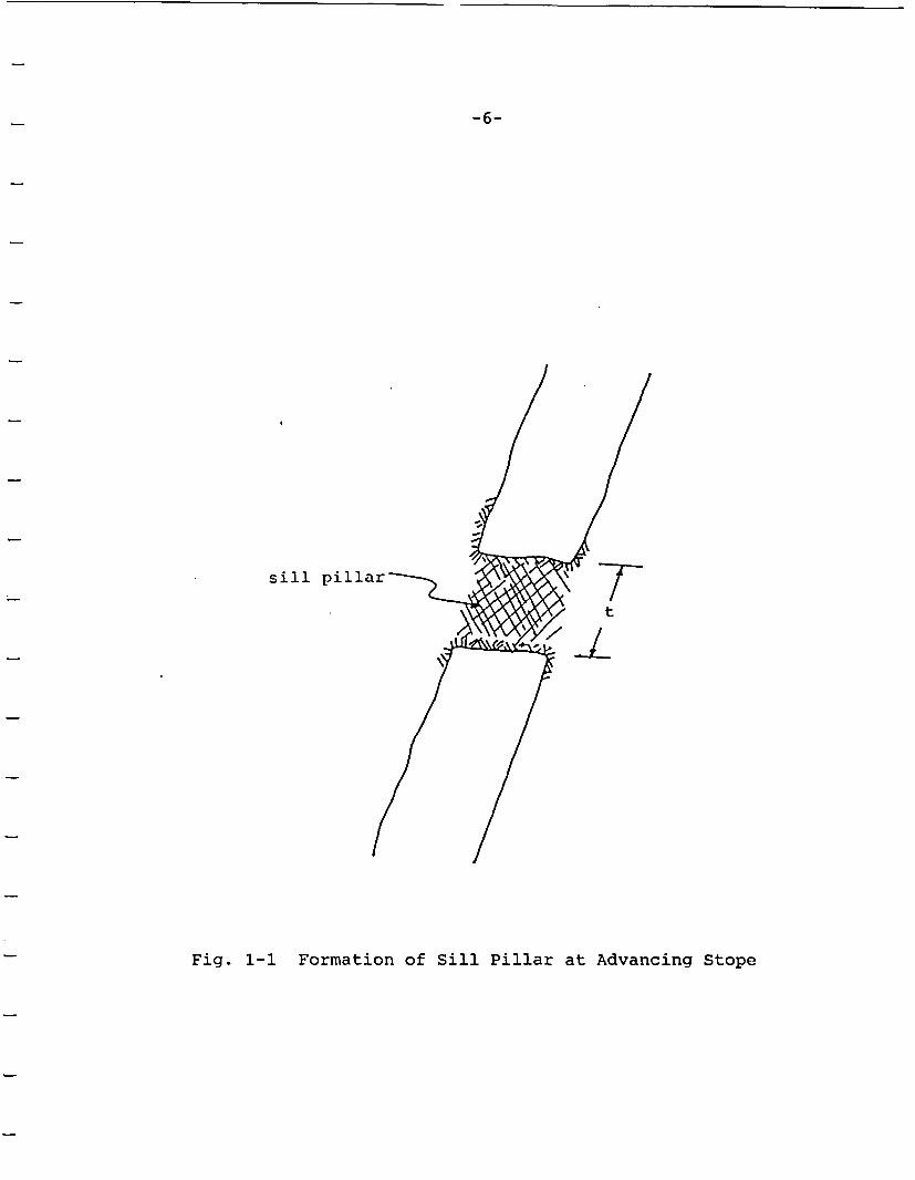
-6-
sill pi
1v Tt-1L
Fig. 1-1 Formation of Sill Pillar at Advancing Stope

-7-
BWIP contractors (Blake, 1984) and Barton (1986) have argued thatthe heavily jointed nature of the basalt (approximately 15 frac-tures per meter or less, depending on location within the flow) isone factor precluding a serious rockbursting problem. In fact,many rock masses having serious rockbursting problems are nearly,if not as heavily fractured as the basalts at Hanford. The joint-ing frequency alone cannot lead to a conclusion regarding rock-bursting.
-8-
2.3 Review of Rockburst Experience
Rockbursting occurs in mining and tunneling on every continentwhere high stresses and hard, brittle rock conditions are en-countered. Primary case examples include deep gold mining inSouth Africa and India, deep metal mining in Canada and the U.S.,deep coal mining in Poland and the U.S., and deep tunneling inScandinavia, Japan and Europe. Some of the well documented caseexamples are discussed here.
2.3.1 Case Histories
The case histories given here are separated between excavation as-sociated with mining and tunneling. The primary difference hereis that mining generally involves multiple (often, irregularly-shaped) excavations with high extraction ratios, whereas tunnelinggenerally involves single openings.
2.3.1.1 Mining
The bulk of rockbursting history occurs in mining of orebodies atgreat depth. Here, several case examples are given to illustratethe general features of rockbursting.
Coeur d'Alene District - Rockbursting has occurred in the Coeurd'Alene mining district of Northern Idaho since the 1920s. Cur-rently, rockbursting represents one of the greatest problems en-countered in mining the deep-seated lead-sliver-zinc veins foundhere. The rockbursting here occurs primarily in pillars between amined-out section of the orebody and an advancing stope. Becausethe bursting at the various mines in this district is similar, theStar Mine will be used as an example.
The rock mass in the Coeur d'Alene is a quartzite which rangesfrom a very hard, brittle quartzite to an impure, argilliticquartzite. The rock mass is bedded, with bed thickness rangingfrom about 150mm to greater than 1 meter. The orebodies aresteeply dipping veins of sulphide ore containing argentiferrousgalena, sphalerite and tetrahedrite. In some cases, this ore con-tains large amounts of quartz. In these instances, bursting canoccur in the orebody itself, but it generally occurs within thehost rock mass. The uniaxial compressive strength of the rockmass is about 150-200 MPa. The maximum horizontal stress is per-pendicular to the orebody and is roughly 70-80 MPa at the 7900level of the Star Mine; the secondary horizontal stress is paral-

- 9 -
lel to the vein and about 50-60 MPa. The vertical stress isroughly 55 MPa. A stress ratio (oHmax/Ov) of about 1.45 exists.
Levels within the mine are driven on 61-meter vertical intervalsand a haulage lateral is driven parallel to the vein approximately30m to 61mn in the wall (Fig. 2-1). Crosscuts are driven to in-tersect the orebody on 61m intervals over its mineable length. Ateach crosscut-orebody intersection, stopes are raised and minedtoward the above level, which is mined out and backfilled. Stopesproceed vertically upward by either blasting the back down througha series of 1.5m cuts (backstoping) or by mining the stope hori-zontally by blasting face rounds in each direction from the raise(breasting). When each face reaches its limit (30m from theraise), a raise round is shot in the back to create access to thenext mining cut. In either case (backstoping or breasting), themined areas are filled with sandfill after approximately 3m ofvertical advance.
Rockbursting occurs in three primary ways (Fig. 2-2):
(1) explosive failure of the pillars or wall rock ad-jacent to the pillars as the pillar height is re-duced below about 30m;
(2) explosive failure of the pillar which occurs betweenadvancing stope faces; and
(3) slip along faults which lie in close proximity tothe orebody.
In general, the first type of rockbursting involves the greatestamount of destruction-often resulting in 500 tons or more of rockexpelled into the stope. These bursts occur from a stope heightof roughly 30m to approximately 55m. The remaining 6m or so ofpillar tends to crush non-violently rather than violently as en-ergy is released through sliding along joint planes or newly cre-ated fracture surfaces.
The second form of bursting generally occurs only during the firstone or two mining cuts as the pillar between advancing stopes isreduced below about 6-7 meters in width. These bursts occurwithin the orebody itself and appear to be related to the factthat the ground is "virgin"-i.e., it has not been exposed to highor changing stress for long periods of time (which tends to inducefracturing or movement along existing fracture surfaces). Thisprocess, known in mining as "natural destressing", is actuallyyielding occurring in the rock surrounding the openings. Because

-10-
B. 4C<~,C LL E
14iN I'J& L6VP&LI-
00N
~At~~~LEV~.' 2
Fig. 2-1 Schematic of Overhand Cut-and-Fill Mining

-11-
/M'tJE D'P. rk~upST LociE-i0ti
6TO)PE I S .ToP f 2 SoT6P 3
( L)
D iECf c rJ O A DVA "CE
u8uxesw L.OTo.J r
SpoPS 1 ~~~~~~~ST°PC2
Cb)ZO Jf OF I JtU6CCD SLIP
FAUL-r ,
/ ~~~ADVA,,ta,
Cc)
Fig. 2-2 Schematic of the Three Types of Rockbursts:(a) bursting occurring from mining of sillpillars; (b) bursting as a result of inter-section of advancing headings; and (c) un-stable slip along faults
-12-
the yield zone is quite small for single openings, there tends tobe a confined core of elastic material within the pillar which mayfail violently if sufficient stresses are applied.
The third type of rockbursting is the result of slip along faultswhich lie adjacent to the stoping area. The stoping apparentlychanges the stress state over areas of the fault sufficient to in-duce slip over limited areas. This slip results in a seismic wavewhich can result in damage within mining areas as a result of re-flection of the tensile pulse. Bursts like these at the Star Mineare often very large, resulting in 3.0 ML or greater events.
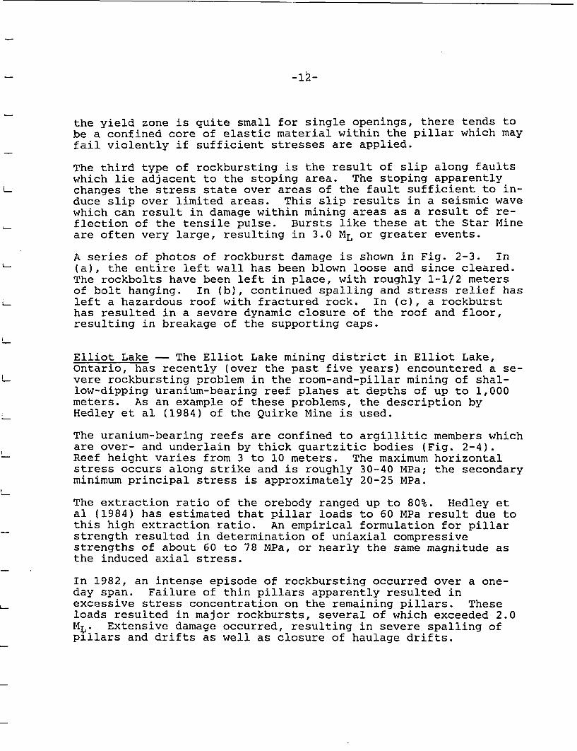
A series of photos of rockburst damage is shown in Fig. 2-3. In(a), the entire left wall has been blown loose and since cleared.The rockbolts have been left in place, with roughly 1-1/2 metersof bolt hanging. In (b), continued spalling and stress relief hasleft a hazardous roof with fractured rock. In (c), a rockbursthas resulted in a severe dynamic closure of the roof and floor,resulting in breakage of the supporting caps.
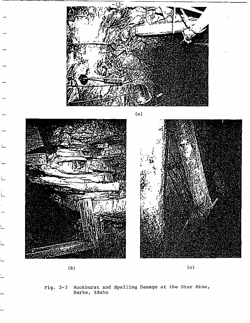
Elliot Lake - The Elliot Lake mining district in Elliot Lake,Ontario, has recently (over the past five years) encountered a se-vere rockbursting problem in the room-and-pillar mining of shal-low-dipping uranium-bearing reef planes at depths of up to 1,000meters. As an example of these problems, the description byHedley et al (1984) of the Quirke Mine is used.
The uranium-bearing reefs are confined to argillitic members whichare over- and underlain by thick quartzitic bodies (Fig. 2-4).Reef height varies from 3 to 10 meters. The maximum horizontalstress occurs along strike and is roughly 30-40 MPa; the secondaryminimum principal stress is approximately 20-25 MPa.
The extraction ratio of the orebody ranged up to 80%. Hedley etal (1984) has estimated that pillar loads to 60 MPa result due tothis high extraction ratio. An empirical formulation for pillarstrength resulted in determination of uniaxial compressivestrengths of about 60 to 78 MPa, or nearly the same magnitude asthe induced axial stress.
In 1982, an intense episode of rockbursting occurred over a one-day span. Failure of thin pillars apparently resulted inexcessive stress concentration on the remaining pillars. Theseloads resulted in major rockbursts, several of which exceeded 2.0M;~. Extensive damage occurred, resulting in severe spalling ofpillars and drifts as well as closure of haulage drifts.
(a)
(b) (c)
Fig. 2-3 Rockburst and Spalling Damage at the Star Mine,Burke, Idaho
-14-
loo ~~~~~~~~~~~~~~~~UMSE"ONE700
200
A~~~~~MI
500 -ACAT
£00
700 -GEkTN
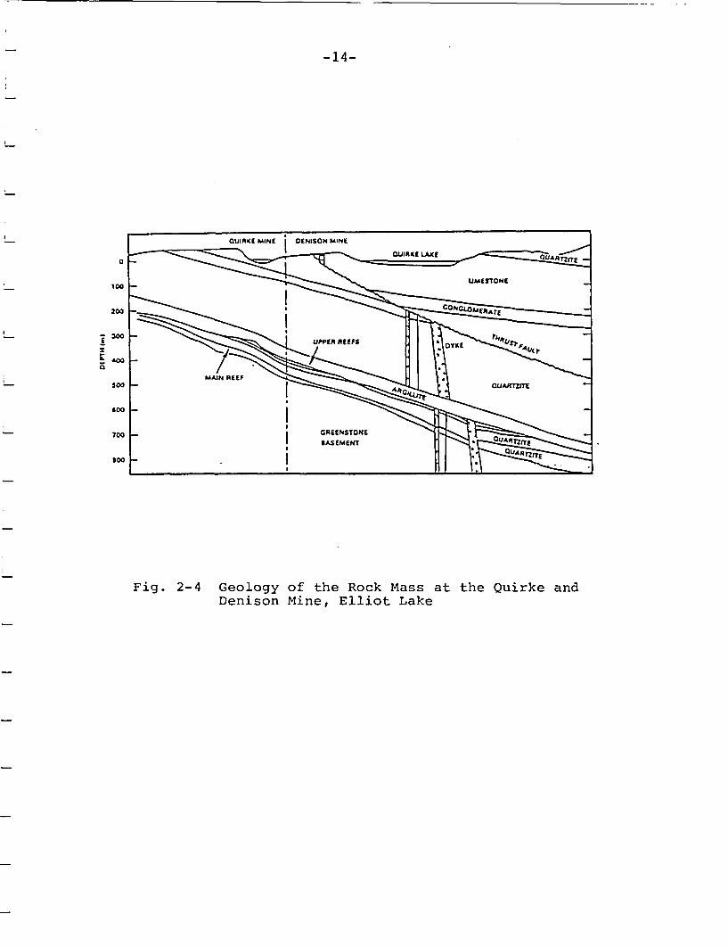
Fig. 2-4 Geology of the Rock Mass at the Quirke andDenison Mine, Elliot Lake
-15-
South African Mines - South African mining perhaps has the worstproblems with rockbursting world-wide. Mining occurs along thin(about 1m thick) gold reefs which dip at 300 or less. The rockmass is brittle quartzites, norite or conglomerates. Depth ofmining is in excess of 3,000 meters. The major principal stressis vertical and roughly equal to the overburden load.
Stoping is accomplished using a longwall face advance. Rockburstsoccur at the intersections of the longwall face with structuressuch as faults or dikes as well as the intersections with otherlongwall faces. Rockbursts at this great depth are often 2-4 ML.The resulting seismic wave often will completely fill the stopewith broken rock or cause the foot and hanging wall to close byhalf the stope height. The majority of rockbursts occur 50m ormore ahead of the stope face and 100m or more above the stopeplane (Ortlepp, 1983).
These bursts are generally recognized to be the result of shearfracture propagation. This mechanism was discussed in detail byOrtlepp (1983). Shear or "burst" fractures were traced by exca-vating in areas of earlier bursting at the ERPM property. Thesefractures contained finely comminuted rock which could be shown tohave propagated through existing solid rock.
Kolar Gold Field - The Kolar Gold Field is located in southeastIndia and contains mines working at depths of 2,000 meters andgreater. The host rock mass is granitic; the orebody occurs asdisseminated gold in schistose rocks. The ore occurs as near-vertical dipping veins. Mining occurs by overhand cut-and-fill ina fashion similar to that discussed previously in the Coeurd'Alene district.
Rockbursting was first reported in the Mysore Committee on Rock-bursting, which convened in 1928. The bursts occur in crown pil-lars created by the overhand stoping and in waste remnants leftbehind. Energy levels of rockbursts are very large and have beengreater than 4 ML. Originally, attempts were made to fill thestopes with cut granitic blocks as backfill as a means of limitingthe convergence of the stope faces, thereby reducing stress con-centration at the face. This procedure met with no success andhas been replaced by standard cemented fills.
-16-
Saskatchewan Potash Mines - Mining-induced seismicity has beenmonitored around southern Saskatchewan potash mines over the past10 years. The geologic section through southern Saskatchewan iscomposed of flat-lying sedimentary rocks to a depth of approxi-mately 1,800 meters. Within this sequence is a series of Devoniancarbonate layers approximately 1,000 meters in thickness whichcontain a halite-sylvite-anhydrite sequence which varies in thick-ness to 200 meters. The sylvite contains economic potash.
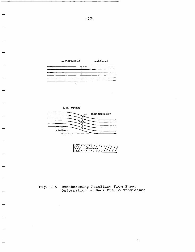
The potash is mined in a room-and-pillar fashion by mechanicalminers. Room dimensions are typically 6m wide by 3m in height.Seismicity was first monitored in the mines surrounding Saskatoonin 1976. Several 2-4 ML events were recorded around the IMC andCory mines, with very little damage reported underground-with theexception of occasional roof-falls. The seismicity has been re-lated to slip along the relatively hard sandstone beds in theoverlying roof of the beds. Creep of the pillars occurs as miningextends, resulting in a time-dependent subsidence of the groundsurface. Gendzwill (1984) reports that interbed shear occurs,resulting in shear failure of the beds over the active miningareas (Fig. 2-5). This shear failure results in the seismicitymonitored underground and on the surface.
Coal Outbursts or Bumps - A coal outburst is essentially theequivalent of a rockburst in hard rock mining. The coal outburstis characterized by a rapid expulsion of coal from a mining faceor pillar into the opening. Gas often accompanies the coal.There is a resulting cavity left, usually in the upper portion ofthe mining face.
Shepard et al. (1981) has discussed the conditions necessary forcoal bumping. First, a minimum depth of 180m appears necessaryfor bumps, with a peak occurrence at 750 meters.
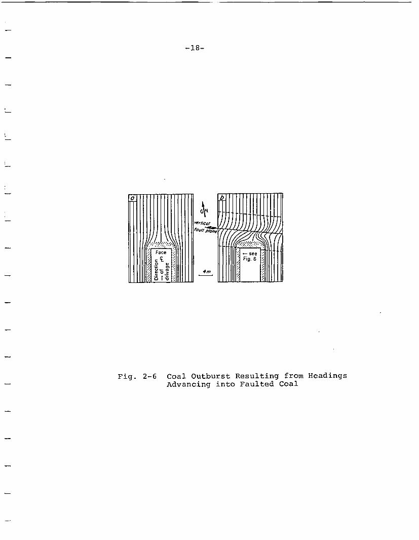
Some geologic structural disturbance increases the possibilitiesof coal bursting by providing a failure localization mechanism.In particular, faulting and folds in the seam have been related tooutbursts. As an example, Shepard, Blackwood and Rixon (1982)discussed bumping at the West Cliff Colliery in New South Wales.Here, outbursts have all occurred on strike-slip faults. The min-ing method is room-and-pillar. As the first panel heading is ad-vanced to within 2 to 5 meters of a fault, the coal and methanegas is ejected 5m or more into the roadway. In some cases, boththe face and ribs of the roadway are fractured. Shepard et al(1984) attribute the outbursts to a redistribution of the horizon-tal stresses between the excavation and fault. This results in anapproximate biaxial stress field ahead of the face which exceedsthe rock mass strength (Fig. 2-6).
ITASCAConsulting Group, Inc.
9 January 1987
David Tiktinsky - SS623U.S. Nuclear Regulatory CommissionDivision of Waste ManagementWashington, D.C. 20555
"NRC Technical Assistancefor Design Reviews"Contract No. NRC-02-85-002FIN D1016
Dear David:
Enclosed please find the draft report "Evaluation of RockburstPotential at the Hanford Site". This report is submitted underTask Order No. 003 of NRC Contract NRC-02-85-002. Please call meif you have any questions.
Sincerely,
Roger D. HartProgram Manager
cc: J. Greeves, Engineering BranchOffice of the Director, NMSSE. Wiggins, Division of Contracts
tDWM Dod&Wnent.C n tro. Ro6om-
Encl.mb/ks
P.O. Box 14806 * Minneapolis, Minnesota 55414 * (612) 623-9599
- 17-
BEFORE MINING undeformed
I
l
I
AFTER MINING
| Mined area
Rockbursting Resulting From ShearDeformation on Beds Due to Subsidence
Fig. 2-5
-18-
Fig. 2-6 Coal Outburst Resulting from HeadingsAdvancing into Faulted Coal
-19-
2.3.1.2 Tunneling
Scandinavia - Rockbursting in civil construction tunnels inScandinavia is a common phenomena. Hanssen and Myvant (1986) de-scribe spalling and rockbursting at hydropower and highway tunnelsin northern Norway. The rock mass in this area consists of Pre-cambrian granitic rocks with a uniaxial compressive strength of 89MPa. Stress measurements were taken at nine sites. The majorprincipal stress at depth in tunnels in the Kobbelv area is hori-zontal at 23 MPa (E-W), with a ratio of horizontal principalstresses of 1.5. The vertical stress varies normally as a func-tion of depth. Large stress differences can be obtained, depend-ing on the proximity to the mountain slope. The tunnels have beendriven by TBM and drill-and-blast methods. Tunnels driven normalto the major horizontal stress exhibit heavy spalling of the roofand floor as well as bursting of the tunnel face. Tension cracksoften occur in the walls of the tunnels due to the high stress de-viation.
Coeur d'Alene District - Rockbursting frequently occurs in theface of advancing single development headings in the Coeur d'Alenedistrict. The general mining method and geology were describedpreviously. The rockbursting is usually small in magnitude-0.5to 1 ML, resulting in fracturing of the face and ejection of rockblocks from the face, roof and walls. In general, these burstswill result in 10 tons or less of ejected material. In additionto the bursting, stress-related phenomena such as spalling of theface and roof will occur as well as squeezing of blastholes.Rather severe damage has occurred in some situations where asingle heading intersects a fault. Here, a rockburst can shakeloose blocks from the roof which border the fault for heights ofup to one tunnel diameter. Other factors which affect rockburst-ing in single headings include intersection of the drift with in-homogeneities such as dikes or an interface of particularly softmaterial with a brittle rock mass. The important point to notehere is that rockbursts do occur in the face of isolated headings,but the magnitude and damage which result are generally much lowerthan the major rockburs5ts associated with mining.
Another interesting case example was the rockbursting at the bot-tom of the Star Mine #4 shaft. Again, the geologic conditionswere described earlier. When sinking the shafts, rockbursts ofmagnitude 0.5 to 1.5 ML would occur, centered beneath the advanc-ing heading. The floor of the shaft was lifted roughly 1 meterand the bottom broken for approximately l-l/2m. The vibration re-sulting from the burst would also often shake loose materials downfrom the walls. From the 7900-8100 levels of the Star Mine, thesebursts occurred with high frequency-about once every 6-lOm of ad-vance.
-20-
2.3.2 Means for Managing Rockbursting
There are two basic methods used by mining companies for managingrockbursting: prediction and prevention. Each of these methodshas met with only limited success.
2.3.2.1 Prevention Methods
The primary rockburst prevention methods are reduction of the ex-traction ratio, variance of the excavation sequences (which min-imize stress concentration), and destress blasting.
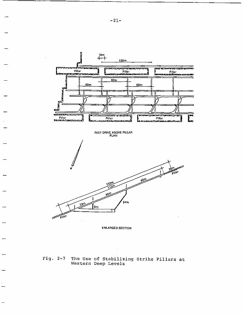
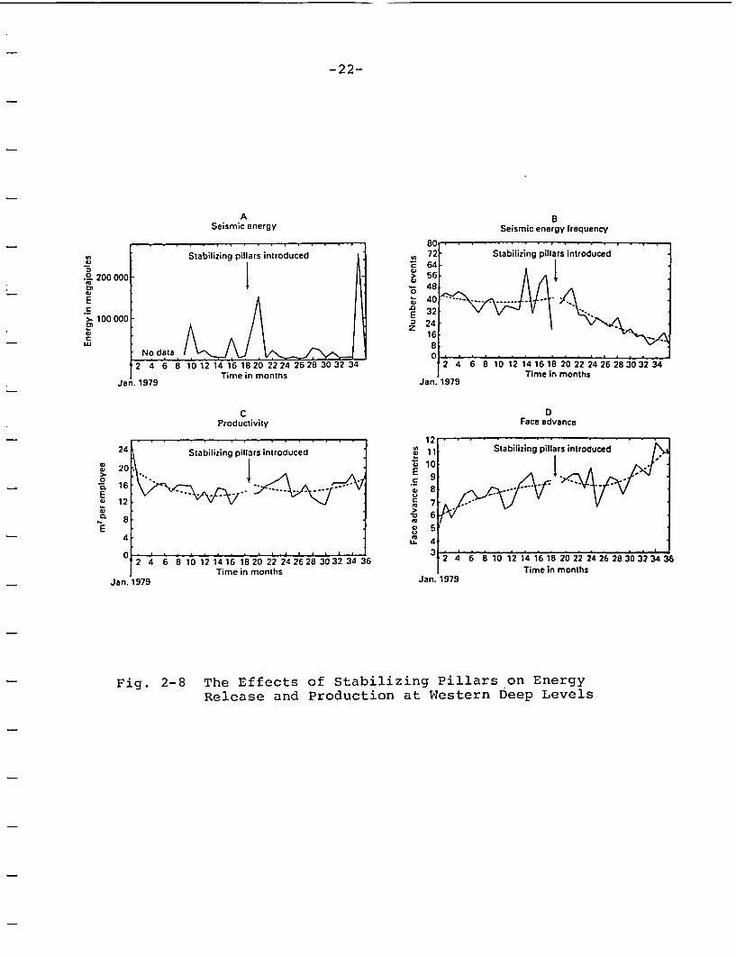
The most certain method of reducing the rockburst frequency is toreduce the extraction ratio by leaving stabilizing pillars. Theuse of stabilizing pillars in deep gold mining at Western DeepLevels is described by Tanton et al (1984). Prior to 1980, miningcommenced by longwall extraction of the gold reef. At this time,it was generally acknowledged that Western Deeps had the most se-vere rockbursting problem in the South African mining industry.Strike pillars were of dimensions 20m wide on 133m centers (Fig.2-7). Figure 2-8 shows the effects of stabilizing pillars. Thetotal energy release (a) is highly variable and not particularlymeaningful. The total number of events (b), however, has steadilydropped since the introduction of the pillars, and the rate offace advance has increased fairly dramatically. The use of pil-lars, in this case, has decreased the rockburst hazard while al-lowing the face advance to increase, resulting in approximatelythe same total production as before the introduction of pillars.
A second, although less certain, means of controlling rockburstsis through the optimization of excavation sequencing to minimizethe stress concentration or spatial rate of energy release. Boardand Crouch (1975) give an example of the use of analog models inplanning stope sequencing for overhand cut-and-fill stopes at theStar Mine in Burke, Idaho. Here, an electrical analog computer isused to determine the spatial rate of energy release for threesequences of a line of overhand stopes. Because, in this case,the orebody extraction is 100%, small differences in stopesequence can be important. In this example, three sequences wereexamined: a flat-back stope, a stair-step style, and an V-styleof stope advance (Fig. 2-9). The accompanying energy release ratecurves illustrate a more constant rate of energy release for theV-type of advance. This is also seen in practice.
-21-
! 60m p: 60m :
99 9
99 9. *.~~~~~~R~
.9 9.~~~~~~~~~~~~-- 7
REEF DRIVE ABOVE PILLARPLAN
N
24m
ENLARGED SECTION
Fig. 2-7 The Use of Stabilizing Strike Pillars atWestern Deep Levels
-22-
A BSeismic energy Seismic energy frequency
- . . , ., , , , , , , ~80 , , , . . .. . . .-Stabilizing pillars introduced 72 Stabilizing pillars introduced
I ~~~~~~~~~~~~~E64-.0 200000 . > 56
E 40. . .
.S ~ N 32a<>0 ,,100 1 12000 12 = 24
5, ~~~~~~~~~~~~~~~~~~16C
No data . _ _ _ _ _ _ _ _ _
2 4 6 8 10 12 14 16 18 20 22 24 26 28 30 32 34 2 4 6 8 10 12 14 16 18 20 22 24 26Time in months Time in months
Jan. 1979 Jan. 1979
C DProductivity Face advance
1224 AStabilizing pillars introduced 11 Stabilizing pillars introduced
5, i 10w) 20.
E-E 0 E- ;9 .Ji127
0~~~~~~~~~~~~~~~~~~~~1 6E I 55
2 4 6 8 10 12 14 16 1820 22 24 26 28 30 32 34 36 2 4 6 8 10 12 14 16 18 20 22 24 26Time in months Time in months
Jan. 1979 Jan. 1979
Fig. 2-8 The Effects of Stabilizing Pillars on EnergyRelease and Production at Western Deep Levels
-23-
305 m (1000 (I)
m (20011)
m (200It)
a) present system
extracted
�, -- , -2
;� 117!ar l.tjocl 115 m (49 11)
b) first alternative (center slope first)
I 15m (4911)
E~ 4 z10'.
I.-
t83.10'
Li
)- a oo .1iiUzUi
c) second alternative (stoirstep sloping)
3 .lo'
tiC twit ..... ifst 0lemwtif tlu~ slope twit)
f ..- __ rcwd ffn o ..im ,wsip slopng)
lo.tO
05:10' , : ..............0 25 50 r:'
EXTRACTION. pecwiK)U
Fig. 2-9 Example of the Use of Energy Release Rate forThree Alternative Methods of Stope Sequencing(The center stope first provides the optimummethod when assuming 100% extraction ratio.)
-24-
Numerical methods are currently heavily used in an attempt to min-imize the rockburst hazard through design optimization. SouthAfrican companies rely on boundary element approaches (in particu-lar, displacement discontinuity) and the determinations of theminimum spatial rate of energy release for design. In the minesin the Sudbury, Ontario, district, International Nickel Corpora-tion uses the boundary integral methods, whereas FalconbridgeNickel uses finite difference and distinct element codes. TheU.S. Bureau of Mimes in Spokane, Washington, performs design stud-ies for the Coeur d'Alene mines using finite element and finitedifference codes. The use of numerical models for correlation torockbursting is in its infancy, and it is not presently (nor willit likely ever be) possible to define with a high degree of cer-tainty if a rockburst will occur under any given circumstances.
Destress blasting is a method by which an attempt is made tosoften the rock mass through blast-induced fracturing or failureso that subsequent energy can be released by plastic deformationof the rock mass rather than violently as in the form of a rock-burst. Destress blasting is an accepted practice in mines in theElliot Lake and Sudbury districts of Canada and in mines inSweden. Some mines in the Coeur d'Alene district in the U.S. usedestress blasting, although several have recently decided not touse large-scale destress blasting.
There are basically two methods of destress blasting. The firstemploys one or more long holes shot with a face round in an ad-vancing heading or stope in an attempt to either "set off" a rock-burst which is imminent or to pre-fracture the ground ahead of theface advance (Fig. 2-10). The utility of this form of destressingis questionable. We are aware of no study which definitely provesif a reduction in rockburst potential occurs from this action.The end result of such destress blasting is usually badly blast-damaged walls which deteriorate rapidly and must be supportedheavily.
The second form of destress blasting is called rock pre-condition-ing by the U.S. Bureau of Mines (Karwoski et al, 1977). In thismethod, a massive blasting is performed using many closely-spacedblastholes prior to excavation. Theoretically, excavation maythen proceed in a zone which has been pre-fractured and which willyield non-violently rather than fail by rockbursting. One par-ticularly successful use of this form of destressing was performedon the Star Mine 7700 level main vein stopes (Karwoski et al,1977). Here, 3"-diameter blastholes were drilled in a radial pat-tern from the stope crosscuts to destress a 200'x200' block of theorebody. These holes were shot with a water gel and milliseconddelays prior to any mining. The shot was very heavy, resulting in
-25-
10-mr,1 ��OStko�ec)
U=II=1l II
!I
I_ r3sr�'. WCLS-Onckes
.. - - .. ~~H
X -Y C.TOr
Kilogran
Total 1
1007 -*-
g
b 14
KEYDark lines show loaded holes 0 3 6
I W WScale, metres
Fig. 2-10 Two Methods of Destress Blasting(The first involves shooting several holes withthe blasting round. The second involves a mas-sive destress blasting to highly fracture therock mass prior to mining.)

-26-
a crushed zone interconnecting the drill holes. Mining proceededin this area without rockbursting-however, seismicity immediatelyresumed when advancing beyond the destressed zone.
A further attempt at this massive destressing was made on the 7900level but failed as a result of drilling problems and delays. Ul-timately, this form of destress blasting in advance of mining re-sulted in higher costs than the rockbursting itself and contrib-uted heavily to the closing of this mine.
In conclusion, destress blasting appears to be helpful in preven-tion of rockbursts but is. sensitive to the magnitude of the de-stressing and the timing of the shot. Apparently, destress blast-ing must be shot heavily to have the desired effect-i.e., to in-duce damage in the rock mass.
2.3.2.2 Prediction Methods
Rockburst prediction is based primarily on the use of microseismicmonitoring methods to locate areas of the rock mass which are ap-proaching failure. As a rock undergoes failure, it emits seismicenergy related to extension of fractures or sliding on existingones. The freque ncy of these events lies somewhere in the rangeof 10 Hz to 5x10 Hz. The microseismic method is used to monitorthe acoustical output of the rock mass as it approaches a violentfailure or as it yields non-violently. A discussion of microseis-mic monitoring in the U.S. can be found in Langstaff (1977), Blake(1971), and Brady and Leighton (1977). The methods in use inSouth African mines are reviewed by Bawden and Kitzinger (1986).
In general, the existing systems consist of geophones (velocitygauge or accelerometer) which are mounted to the rock mass at thetunnel wall or at depth in a borehole (Fig. 2-11). A pre-ampli-fier is used at the geophone to boost the signal to the locationof the data acquisition system (several thousand meters). At thispoint, the signal can be amplified and/or filtered prior to datareduction. Most systems employ a comparison device at this stageto examine the incoming signals against some threshold amplitude.Once a signal has been received which meets the threshold criter-ion, a time window is held open for a certain period, during whichthe computer waits for additional signals from other geophones tobe received. From these arrival times, a least squares method isused to locate the coordinate of the event.

II I I I I I I I I I I I I I I I I I
One vertical componentgeophone on surface(for energy levelmeasurement )
A to D 96channel capacity64 used (Preston)
_.-
a. -
.- __
.;..- W..~
a -
mu_.-
* .__
.............
: ::::::-:-.. ::
l ".w-""R'-'-R'l :::::::::. S::- ::::I :::::::::::::::R:::-:--l '::::::::: :, ::.'.:I ::: :-::::: :- -,-.-,:'.:: .-..*...
, .R. ,RR,
l R: ''.--"-R-"'':::::'.:::.:R:::. .:i:::::.'.::-,::::: :-: :-
::S:: .-:::::::: ::::SR:R:::::::::::::R
, ...
.......... .
..... .......... . ......
.. :::: :: .:-::: .:::::. :
....:::.-.:...::-::
Keyboard
I A::::- :; .;:: I
*:"i -- ....
-3
Shielded.twisted pairs
16 - 33 channel capacity _-" ....... . . Lightning protected
13 x 3 Geospace ~~~~~~~differential input13 x 3 Geospace 4.. L-.._ amplifiers
HSI geophones 4.5 Hz Under- Surface 64 channels used.biamplified preamps.grudntaasgfies
powered from 525V line ~at 500 H'z low pass
HP 1000 Recorder
System bandwidth4.5-500 Hz
L
Fig. 2-11 A Typical Microseismic System In Use at Western Deep Levels(Here, standard velocity gauges are used. The signal is am-plified and the A-to-D converters are used to digitize thewaveform.)

-28-
In addition to coordinate location, the event energy content mayalso be established in real time. Also, some systems possess theability to perform spectral analysis in real time; others will re-cord selected waveforms on tape in analog form (or digitally, ondisk) for further spectral processing.
To date, the primary use of the data has been to examine countrate of seismic events as a function of time. It is generallypossible to see an increase in seismic activity in the area inwhich the rockburst will occur in the days preceding the event.It is, however, rare that the data can be used to pinpoint thetime of the event to an accuracy such that personnel may beremoved from the area.
An example of such a case is illustrated in Fig. 2-12 (Langstaff,1977). Here, a definite microseismic signature in count rate pre-ceded a rockburst at the Star Mine. A dramatic increase in countrate occurs for roughly 15 minutes, followed by a complete absenceof noise for roughly 30-45 minutes. A 3ML burst occurred at theend of this quiet time. This type of signature, unfortunately,occurs rarely. There are many examples of large rockbursts whichoccurred without warning. Present research is aimed at the use ofaccelerometers to provide high frequency data in addition to pre-sent broad-band systems. This frequency spectrum and energy con-tact of this data can then be analyzed for shifts analogous tothose which occur in laboratory testing of brittle rocks.
-29-
ROCK BURST-SEPT. 3,19759 MAIN VEIN, 7500 LEVEL
t2 20zLiJ
0106z
.5
HOUR
Fig. 2-12 Typical Microseismic Build-Up Prior toa Major Rockburst at the Star Mine
-30-
2.3.2.3 Reduction of Damage Effects from Rockbursting
Large rockbursts which sometimes occur in mining can displace hun-dreds to thousands of tons of broken rock into an opening. It isdifficult to provide any type of support which can reduce the dam-age from this form of bursting. For small bursts (i.e., <0.5-1ML), rock support can be beneficial in keeping rock blocks pinnedto the back. A common method used in South Africa and Canada isfully-grouted rebar rockbolts with wire rope lacing and chainlinkfencing (Fig. 2-12). The chainlink fencing will trap blocks frombeing ejected from the back while the wire rope lacing gives aflexible and strong support to the chainlink. Perhaps the bestmeans of support is shotcrete-particularly wire-reinforced, asused in Scandinavian countries.
chainlink fencing(removed to illustratecable slings)
7 //bgroutedbars
0. 8m
Fig. 2-13 Rockbolt Support with Wire Mesh and Rope Lacing

-31-
3.0 GEOLOGIC SETTING OF THE HANFORD SITE
The Hanford Nuclear Reservation is in southeastern WashingtonState and is located within the Pasco Basin, a topographic featurewithin the Columbia Plateau (Fig. 3-1). The Pasco Basin is under-lain by over 50 distinct basalt flows comprising a total depth ofover 3,000 meters (Fig. 3-2).
Of particular interest to the present study is the tectonic set-ting of the Basin. East-West trending ridges of the Yakima FoldBelt bound the Pasco Basin on the north and south, plunging intothe Basin from the west. The Cold Creek Syncline is one of a num-ber of subtle folds which lie sub-parallel to the major east-westtrending ridges. The Cold Creek Syncline appears to be free ofmajor bedrock structures and has a nearly flat-lying dip (<5°).The eastern margin of the Basin is the north-trending Jackassmonocline, east of which the basalt thins. Within the basin,thrust and reverse faults are found sub-parallel to the east-westtrending folds. Within the Yakima Fold Belt, steeply-dippingnorthwest- and northeast-trending faults are found (Caggiano andDuncan, 1983).
Within the confines of the Hanford site, a preferred "referencerepository location (RRL)" has been chosen (Fig. 3-3). TheCohassett flow, at a depth of approximately 900 meters within theRRL, was chosen as the preferred horizon for repository develop-ment.
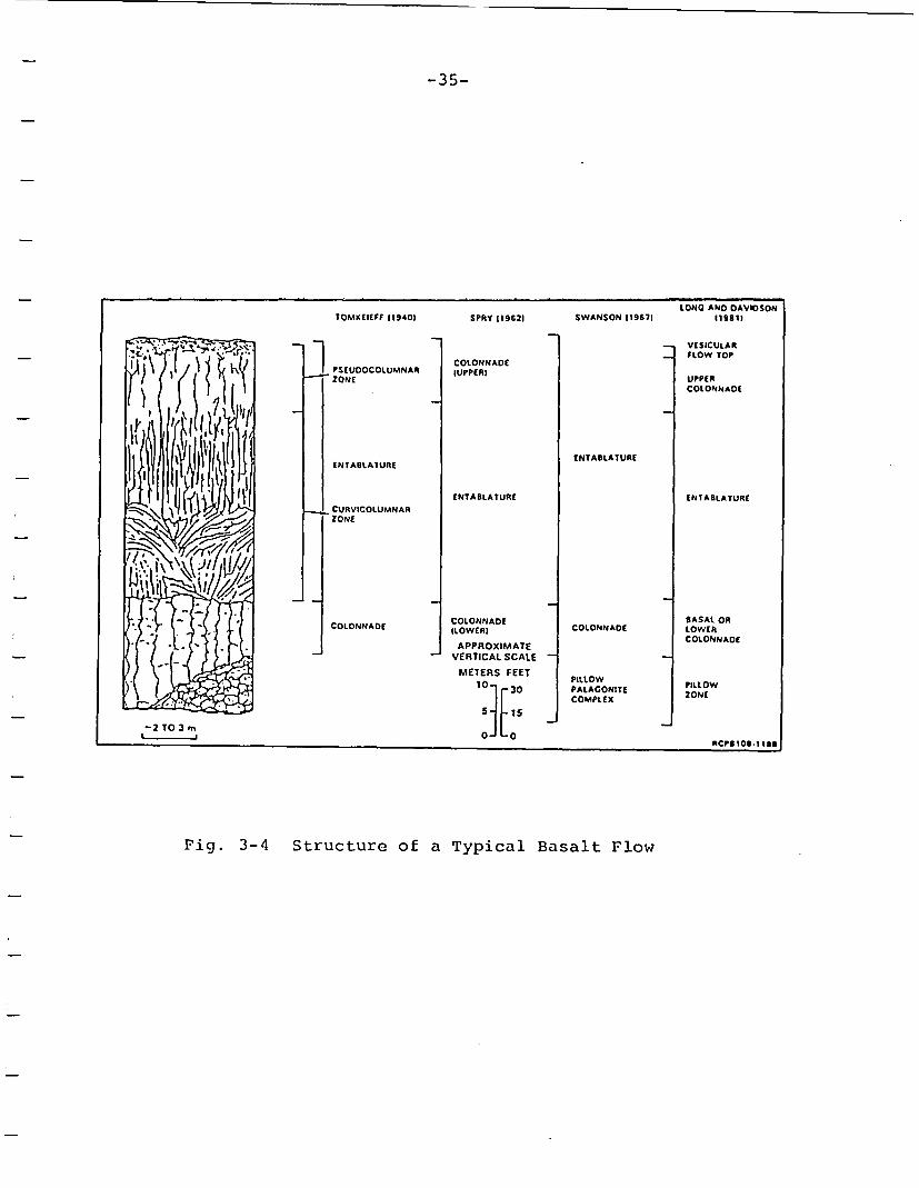
A typical basalt flow has a highly variable structure both verti-cally and horizontally. There are, in general, three distinctunits to a flow: the flow top, entablature, and colonnade (Fig.3-4). The flow top consists of the vesicular and/or brecciatedcrust of the flow which was cooled rather quickly after deposi-tion. The flow top grades into a vesicular zone which, in turn,grades into the fractured dense interior portions.
-32-
Fig. 3-1 Location of the Pasco Basin and the Hanford Site
-33-
. , , I I
6.� 0 00 - 4-
� �;3 t4 � f
4� t� � 0�� 0 4, � 4-4
A
MEMBtROR SEOUENCE
SEDIMENTSTR AT IC RAP H V
OR BASALT FlOWS
^ ^ r r ^ -^ ______________________ S I-
cc
I'-4
0
"CIU I
611
0.
0.
II 01o I I
I1 l4ivI %II a I I
" I~ : 1SURFICIAL UNITS
_ TOUCHET BEDS~I
:GRAVELS: PA SCO U= = _ ~~~~~~~~~~~~PLIO PLEISTlOCENE UNIT
0
sC
UPPER RINGOLD
MIDDLE RINGOLD FANGLOMERAT
LOWER RINGOLD
BASAL RINGOLD-1-4-4-P-I P
85
105
120
ICt HARBOR MEMBER
GOOSE ISLAND FLOW
MARTINDALE FLOW
BASIN CITY FLOW
C
0
V)
ELEPHANT MOUNTAIN MEMBER
LEVEY INTERtED
UPPER ELEPHANT MOUNTAIN FLOW
LOWER ELEPHANT MOUNTAIN FLOW
RATTLESNAKE RIDGE INTER8ED
UPPER POMONA FLOW
LOWER POMONA FLOWPOMONA MEMBER
fSOUATZEL MEMBER
SELAH INTERBED
UPPER CABLE MOUNTAIN FLOW
GABLE MOUNTAIN INTERBED
LOWER GABLE MOUNTAIN FLOW
COLO CREEK INTERBED
C
C- cCU1.U0
a'
,3EI0z
ASOTSN MEMBER
C-
.0to
E'i.
HUNTZINGER FLOW
_ 13 6
E
1
WILBUR CREEK MEMBER WAHEUKt FLOW
SLUIFLOWUMATILLA MEMBER UMAILOA FLOW
MABTON INTERBED
PRIEST RAPIDS MEMBER EOEO FLOWROSALIA FLOWS
OUINCY INTER8ED
UPPER RDZA FLOWROZA MEMBER
LOWER ROZA FLOW
SQUAW CREEK INTtRBED
FRENCHMAN SPRINGS MEMBER APHYRIC FLOWSPHYRIC FLOWS
_ _ VANTAGE INTERBED
UNDIFFERENTIATED FLOWS
i UNMEO FLOW
SENTINEL BLUFFS SEOUENCE .,;COWASSEftOw -
UNDIFFERENTIAIED FLOWS
MTCANON FLOW . :'--'.' t
________________TE MUF LOW
z0
Z
r0
I
156
'a
toV
r00. _.. LOW Mg FEOW ABOVE UMTANUM4'1C_ SCHWANA SEQUENCE
| 6 I
= CANDIDATE REPOSITORY HORIZONS
I :UMTANUM FLOW - I 4
HIGH Mg FLOWS BELOW UMTANUM
VERY HIGH Mg FLOW
IAT LEAST 30 LOW My FLOWS
RCPFlOES IF
NOTE: The position of the Grand Ronde 7 in Borehole RRL-2 is immediatelyabove the McCoy Canyon flow.
Fig. 3-1 Stratigraphy of the Columbia River Basalt Groupand the Candidate Repository Horizons
-34-
Fig. 3-3 Location of the Reference Repository Location(RRL) Within the Hanford Site
-35-
LONC AND DAVIDSON
TOMKEIEFF 119401 SPRY119621 SWANSON 119671 119811
-1 _ VESICULAR
u FLOW TOPCOLONNADE F
W -X~ I v PSEUDOCOLUMNAR dUPPERIK ~ ~~~~~ ~~ZONE UPPERe(I - | > '; t COLONNADE
{~{ .e~t7 SE ENTABLATURE
fl ~~~~~~~~~~~~~ENTABLATURE ENTABLATURE
CURVICOLUMNARZONE
* -- ~ ~ ~~~~CLNAD OONAECOLONNADE BASAL ORCOLONNADE ~ILOWERI CLNAELOWER
APPROXIMATECONADVERTICAL SCALE
METERS FEET PILLOW PILlO
COMPLEX ZN
PALACOMTE ~~RCPS1OS-1 188-2 TO 3 m
Fig. 3-4 Structure of a Typical Basalt Flow
-36-
The entablature and colonnade are generally classed as the "denseinterior" by BWIP. The entablature of the flow is heavily frac-tured, often with fanning or poorly-formed hexagonal columnarstructures. The fracture frequency is variable but ranges fromabout 5 to 20 fractures/meter (Long, 1983). The basal colonnadeof a flow generally has a regular hexagonal columnar structurewith near vertical cooling fractures. The columns are cut by sub-horizontal, discontinuous cross joints. The joints in theCohassett flow are most often healed with secondary mineralizationor indurated clays. These infillings give a fairly high strengthto the joints. Another feature of importance is the interlockingnature of joints in basalt which should enhance stability. Thebase of the flow generally consists of a thin brecciated layerless than 1 meter in thickness.
These three flow subdivisions are not present as distinct units inall flows. Some flows lack an entablature, whereas others mayhave alternating entablature and colonnade. The thickness of thethree zones is also highly variable from flow to flow. TheCohassett flow consists of alternating entablatures and colonnadescapped by a flow top. The flow is relatively uniform in thick-ness, with less well developed fanning columns, as seen in out-crop. The following description of the Cohassett flow from out-crop mapping is taken from Long (1983).
The flow is an aphyric to sparsely phyric, dense basaltflow, with multiple tiers of entablature and colonnadein the lower half of the flow. Column diameters have anestimated range from = 1.5m near the base of the flow to= 0.2m in parts of the entablature. In places, the en-tablature and colonnade tiers are separated by nearlyhorizontal platy fracture zones and in other placesplaty zones occur within entablature or colonnade (seeLong, 1978). These platy zones undulate in places andconsist of multiple anastomosing fractures rather than asingle planar fracture. Upward from the center of theflow the basalt becomes locally vesicular, with vesiclelayers developed in an abundantly vesicular zone. Cool-ing joints extend undisturbed through the vesicular zoneinto the overlying dense basalt. The contact of thiszone with overlying dense basalt is sharp and nearlyplanar and can be traced along the exposure at SentinelGap. The flow is capped by a relatively thin (=6m) red-dish, scoriaceous flow top. Vesicles in the zone justbelow the oxidated flow top are typically isolated fromone another, and the rock is columnar basalt except forthe vesiculation (i.e., brecciation is not developed).

-37-
It is important to note the structural variability of theCohassett flow both vertically and horizontally. The flow has atiered structure consisting of variable thickness alternating en-tablature and colonnade layers. It is highly likely that the re-pository drifts will cross these intraflow structures many times.It is also possible that drifting may intersect the interior ves-icular zone.
The intact basalt is a highly brittle, elastic, and strong rock.Table 3-1 summarizes the relevant mechanical properties of the in-tact Cohassett flow (Sublette, 1986).
3.1 In-Situ State of Stress
Since the beginnings of site investigations at Hanford in the mid-1970s, it has been seen that a sizeable percentage of the core re-trieved from diamond drill holes is disked. Disking is a phenome-non indicative of high magnitude (and highly deviatoric) horizon-tal stresses and is normally encountered in deep mining. Furtherevidence or high stresses and possible rock instability was seenfrom spalled exploration borehole walls as well as from the inci-dence of extensive shallow seismicity beneath the site. All ofthese phenomena prompted an investigation into the field measure-ment of the principal stresses at depth using the hydraulic frac-turing technique.
The stress-related phenomena, field measurements, and data analy-sis have been reviewed by Kim et al (1986). Of importance to thepossibility of rockbursting at the site are four related phenom-ena: seismicity, borehole spalling, core disking, and the in-situmeasurements themselves.
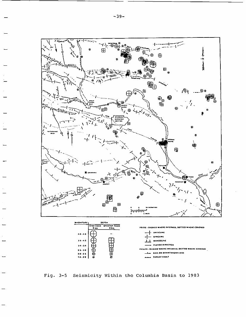
3.1.1 Seismicity
Seismicity in the Columbia Plateau is commonplace and occurs inthe form of earthquake swarms (Rohay and Davis, 1983). Earthquakeswarms are composed of approximately 100 events of Richter magni-tude 1.0 to 3.5 which last a few days to months. The volume of atypical swarm is approximately 5km on a side. Approximately 75%of the earthquakes occur at depths less than 4km, 80% of which oc-cur during earthquake swarms (Rohay and Davis, 1983).
The earthquake swarm activity is heaviest along the Saddle Moun-tain and Frenchman Hills Structures, as well as Wooded Islandalong the Cold Creek Syncline at the Columbia River (Fig. 3-5).These swarms indicate active yield, presumably along fault struc-tures related to regional folding.

I I I I I I I I I . I I I I I I I - I I
Table 1
Relevant Mechanical Properties of the Intact Cohassett Flow[Sublette, 1986]
G(ratde Ronde Foimation. Girande Romile Formation extluding Pomona Member of Saddleullitditiim flow unly Umtanum ddta Mountains Formation
Rarige Medn' Range Mein' Range Mean,
Bulkl d~esity(1Jtmi) 241-301 270 ±005 259-2 85 2.18 ±005 269-289 2.85 ±0.03
(irfin dIeJMSIty (4j/(m 2 /8 - 3 10 2 30 ±008 . .. 26 3 18 3 00 ±0 08
Aliprietit pimrtisity( 0 ) 02-30 1 1 04 20-53 34 t 13 0.1-2.2 0.7 ±0.4
7l0Idl 1MImlmty (')0 4 - 9.7 3 6± 2 4 7.0 - 13 7 10 3 ± 2 4 1 0 . 8 1 4.8 ±2.0
YouJig's mudlulus(statlC)(MPd) 54,000-94.500 71,000 ±20,000 48,900-86,100 64.800 ± 16,000 74.500- 112.400 83.400 ±8.300
Polssol s ratitm (stdtm) 0 15 * 0 32 0 27 ±005 0 21 * 0 27 0 24 0 04 0 22 -0 36 0.25 0 02
Young's modulus (dynamic) (MPa) 66.900 - 102.000 80.000 ± 7./00 .. .. 70.900 -91,800 82.500 ± 4,200
Pulssoliss.Itio(dynidmi) 0.15-032 024 ±004 .. .. 020.032 026 ±001
Cornmpre.ssioidl wave velocity (m/s) S.360 * 6.430 5.860 t 310 ,, ,, 5.560 .6.290 5.930 ! 160
Shear w.ve velocity (mis) 3.080- 3,900 3.420 180 .. .. 3,070-3.510 3,390 90
azilmlil at.-nsile sttength (MKI.) 1 4 23 7 11 9 ±6 9 8 0 24 0 17 2 5 1 9 4 - 28.5 19.4 * 3 8
Compressive strength (Mp)d)uritoilfiied 81 .369 212 l 1 OC . 266 -416 356 ±42
Culifill d at:IJUMId .. .. .. .. 434 -525 490 35c34 5 MWi.l 357 * 671 420 ! 90b ,,
Ai iij tuI mii vi iiaI Ii i.t timni (deg)(.t T 2U'() .. 44 .. .. .. 53
(mitesfiol (MPd) . 45 .. .. 59
NOTE. Datd taIeis fruu ( SM (978), Duvall t al (1978); FSI (1980a. 1980h); FSI (198 1a. 1981 b); Hulstrom (1982a, 1982b); Miller (1979a. 1979b);Mill.. .indl Hish)p (1919); Sctimift %t if (1'980); filtler (198/)
*D.ltd Is lIeselted dS 0 rIledil vaIUe ± I stanidard devidtlOll"1A iledar legrefiSSIuii .ilyIs onf ildtd at several (trifining levels yields the following relationship:
Comnpressive stieri'jth - 2344 5 7 x (oififimnig stress in MPd)
'A Ilicirt icression of da.t.i .i several rolifiriliri levels yields the following relationship:( wmipressive stleiijilh * 254 4 * 8 87 x (ronfinirig stress III MPa)
da ,z taiJtrf dssurnihj tlhte M.lui (Uuluinb failure (riterion
WCO00
- 39-
MACGIT0DI
40 .4.
s.-40
3 0 .3.S
2.S . 2.0
2.0 .2.1
*.S . 2.0
DIPTM
LESS THANI ONEATIS THAN
49 ED
lOVS. 0A5141 NHE At IN# ERE D. DOTTED WM$lPC CaVI RED
-4 ANtICLINE
- SYNCLIPIE
MON10 OCLINI
P&uN0E OIPICIION
FAULTS -DVASHED WMERE INF9PRID; 0O1110 "WHERE COVERED
..L.. PALL ON DONAITIEROWN sIoE
-THRUST FAULT
Fig. 3-5 Seismicity Within the Columbia Basin to 1983
-40-
Focal mechanisms of the earthquakes indicate a horizontal north-south maximum compression with minimum vertical compression.Thus, there is an apparent thrust mechanism on east-west strikingfaults, which is in agreement with surface mapping in the ridgestructure north and west of the site. There is no measured shal-low swarm activity directly within the RRL.
3.1.2 Borehole Spalling
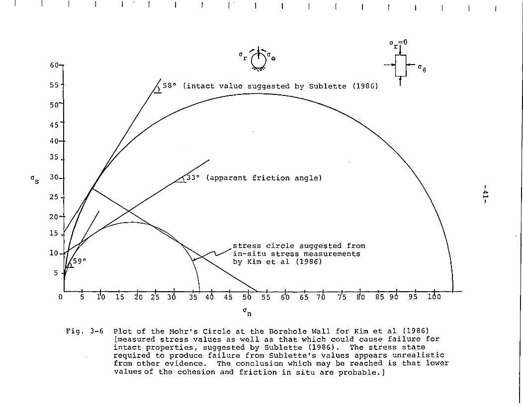
Downhole television and acoustic televiewer surveys of explorationboreholes have indicated borewall spalling or breakout along theeast-west axis of the holes (Paillet, 1985). Borehole spallingoccurs when the maximum stresses induced around the borewall re-sults in shear failure of the hole wall at 900 orientations to themaximum horizontal stress. Because the holes are of small diame-ter (6"¢ or less), this failure is essentially in intact rock.The primary conclusion which can be drawn from the presence ofborehole breakout is that high stresses exist in the rock masswhich are sufficient to cause failure of the intact rock aroundthe hole. To produce such failure with the measured stresses re-quires friction and/or cohesion values lower in magnitude thanthose suggested by Sublette (1986) for intact basalt. This isillustrated in the Mohr circle plot of Fig. 3-6. Two stressstates are plotted: the borehole stresses produced by the mea-sured stresses and the stress state necessary to produce wallshear failure given the laboratory intact properties (Sublette,1986). The latter would require near equal horizontal stresses,which does not appear to be supported by other evidence such asdisking and fault slippage.
3.1.3 Core Disking
In the mining industry, the phenomenon of core disking has beenrecognized as an indicator of high stresses for many years. Coredisking occurs when drilling diamond drill holes into highly-stressed rock. The bottom "stub" of the core will split off toform a disk whose thickness is related to the magnitude of thestress. Lehnhoff et al (1982) examined the disking problem numer-ically using a finite element analysis and developed correlationsbetween disk thickness and shape and the direction, magnitude, andratio of the principal stresses. The conclusion of this study wasthat the major principal stress is oriented in a north-south di-rection with ratios of the horizontal principal stresses of 1.2:1to 1.5:1.
I I I I I , I I I I I I I I I I I I I I
ar a
asI
J�-�-A
I
an
Fig. 3-6 Plot of the Mohr's Circle at the Borehole Wall for Kim et al (1986)[measured stress values as well as that which could cause failure forintact properties, suggested by Sublette (1986). The stress staterequired to produce failure from Sublette's values appears unrealisticfrom other evidence. The conclusion which may be reached is that lowervaluesof the cohesion and friction in situ are probable.]

-42-
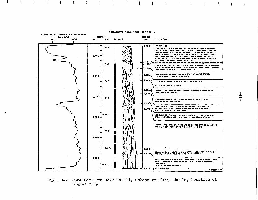
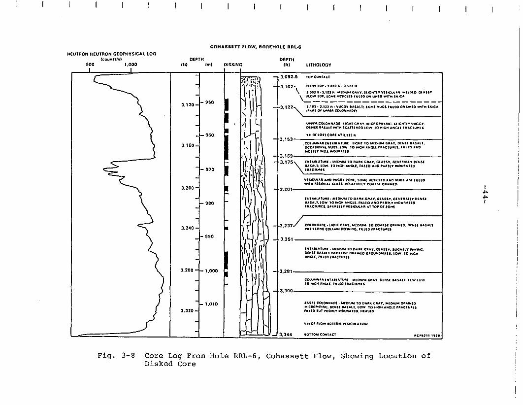
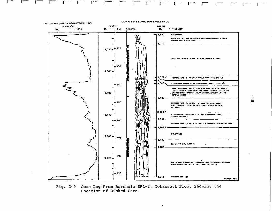
An interesting point regarding the disking is its frequency of oc-currence in the Cohassett flow in various drill holes on the site.The percentage of total core which was disked from the dense in-terior ranges from 9% in borehole RRL-6 to 64% in RRL-14, with anaverage of 30% for all holes in the RRL (Long, 1983). This is incontrast to other flows with higher glass content-such as theUmtanum, which showed 73% disked core. Figures 3-7 to 3-9 showdrilling and geophysical logs of the Cohassett flow and the disk-ing observed.
In summary, disked core encountered in mining indicates high lev-els of rock stress. In general, disking core also indicates thehigh probability of ground control problems when mining throughthe ground.
3.1.4 In-Situ Stress Measurements
The in-situ stress state has been determined by hydraulic fractur-ing measurements in the Grande Ronde flows (Kim et al, 1986). Themeasurements show unusually high horizontal stresses which do notvary lithostatically. The above report suggests the followingstresses at the Cohassett Flow:
aHmax = 60 +15/-10 MPa, north-south
GHmin = 33 +4/-4 MPa, east-west
avert = 24 MPa
A plot of the measured stress ratios as a function of depth isshown in Fig. 3-10. The important point to note in this plot isthe high deviation in stresses. The value of aHmax/av averages2.3 in total but averages 2.54±0.36 (2 standard Deviations) in theCohassett flow. Figure 3-11 shows that the average horizontal tovertical stress ratio at Hanford is on the upper range for stressratio from world-wide measurements. This plot is somewhat mis-leading, since it plots the average horizontal stresses.
In conclusion, the indications of stress at the Hanford site showthat an unusually high magnitude of horizontal stress and ratio ofhorizontal to vertical stresses exists at the RRL. Further, thereis abundant evidence of rock failure in response to thesestresses, including disking, borehole spalling, and microearth-quake swarms. These same indications are present in mining dis-tricts which experience stress-related ground control problemssuch as rockbursting, spalling, and general wall and roof slough-ing failures.
I I I I I I I I I I I I * I I I I I I
NEUTRON-NEUTRON GEOPiHYSICAL LOGlCOUnISl19
600 1.000I I
COHASSETT FLOW, BOREHOLE RRL-14
OEPTH DEPTHlltl tml DISKING fill LITHOLOGY
z
3.082
3.113.5-.3.116-
.3138
* 3.147.6
3.165.5
-3.t93.
-3.203~
*3.282 -
.3.291 \
Top CONTACT
FLOW TO1 . FLOW TOP *ABCCIA. OLASSY ?IYTRC CtAStS IN ALTIRSO.DIMt ORAIFID. CLASTIC. PAtACONITIC MATRIX. LARGCE AND A11UIDANEOPEN AND tlIND VUCS. AIUNOANT VtSOCtTS. SOC~t OPEN FRACIURESAND FISSURES: AT 3.0 l h. IT CUAOES WFO VUGGY. M1ASSWE1 LIGHTGRAY. MEDIUM CRAIlED BASALT; FRACTURES ALTERED. AT 3 III h.FLOW TOP ERICCIA RECURS. MORE OXIOD THAN ABOVE, IT CRACESINTO VESICULAR BASALT tNOIa AT 3.11B fl
COtONNADO .3.1121 3.11 sh tLGHT TO MtOIUM GRAY.r MEDU CGAIINE.StLIHrtYrpANfRlTC BASAT. FEWHORIZONTAL TOtG_ AMCt. N1AIUDFRACTURES. SOMf SCArTEREFtIVtS vtsatS
COCUMNAAR ENTAIRATURE .MEIOtI GRAY. APhtAMTIC BASAIT;ftW M4GM ANGLE. HAIRLINE FR.ACTURES
COLONNADE . LIGHT To 10MDIUM CRAY. DTIISt BASALT
LOST S 11t o COAL At 31421i
ENtABLATURE . MEDIUM TO DARS GRAY. APEANPATIC BASALT. WITHFIttED VRTICAL FRACTURES
COLONNADE .LIGHT GRAY. DENSE. P*EAtlEITIC BASALT. SOLtHIGH ANGLE. OPEN FRACTURES
(Ii
ENTABLATURE f NTABLATURE WITH INTE RNAL Vt SECULAl ZONEAT 3.113 . 3.203 h. UPPER PORTION Of INTABLATURE IS OARSKCRAY. FINEGRAINlD. DENSf BASALT
VESICULAR tONE. COARSE GR AINED. SIGHTLY PhYIPIC. VfSICtALARBASALT: SOME SILICA FILLED VESICLES NEAR xOnOM OF ZONE
ENTABLATURf . CAPE GRAY. MEO"uM TO COARSE CRAINEC. FtIANERITICBASALT. BECOMES PHASURITIC AND APARC AT 3 3431 t
COLUMNAR ENTABLATURE . MEDIUM GRAY. DENSE. SLOIHTLY P"RICBASALT; FEW tOW ANGLE. POORtY HEALED FRACTUMES
3.300BASAL COLONNADE .MEOIUM TO LOIHT GRAY. SLIGHTLY PIH4YRC. DEtStBASALT; MEDIUM TO HOCH ANGLE, FILLED. BUT POORLY tbOURATEOfFIACTURs
I h Of FLOW BOTTOM RUSBBE
3.3211 IBOTTOM CONTACT -RCill1I slB
_ _
...... ___
Fig. 3-7 Core Log from Hole RRL-14, Cohassett Flow, Showing Location ofDisked Core
I I I I I I I I I I IIIIIIIII
COHASSETT FLOW. BOREHOLE RRL.6
NEUTRON NEUTRON GEOPHYSICAL LOG(eountsts)
500 1.000I I
DEPTH(II) IM)
DEPTHDIII LITHOLOGYDISKING
I I
CZ-- 3.092.5 TOP CONTACT
3.120-
3.160 -
3,200 -
3.240 -
3.280 -
3.320 -
- 950
- 960
- 970
- 980
- 990
- 1,000
- 1.010
'3.102- FLOW TOP * 3.0 2 * * 3.122 f
\\ 092 S. 3.102 h uMDoUM CRAY. SLIGHTLY VISICUEAR WELODO GLASSYFLOW tOP. SOME VISICltS FKILED Of LIMED WITH SKICA
-3,1 22 t 102 3122 h . VUGGY BASALT: SO#E( VUGt FlLED OR 11tD WITH SILICA\ tPART Of LIMIT C7COLONA^Of
UWPf A COLONNADE IkIGHT GRAY. MACROPHYRIC. SlIGHtlY VUGGY.DENSE BASALt WITH SCAITREtO LOW TO HMGH ANGII tRACIUMI S
I h Of LOST CORE Al 3133t h
3. 1DJ, . _COtUMMAR ITAMKATURt tIGHT TO MEDIUM CRAY. DtNSE BASALT.OCCASIONIL VUGS. LOW TO HIGH ANGLE FRACTURES. IRLEo ANDMOSTLY WILL INOURATED
3.1693.175\ ENTABLATURE. MEDIUM 1O ODkB GRAY. GLASSY. GENTRALLY DENSE
\ ASALT: LOW TO HIGH ANGLE. FILLED AND PARTLY IDOURATED,RACTUAES
VESICUIAR ANO VUGCY ZONt; SOME VtSICtES ANO VUGS ARE FILLEDWITHE RtSIOOAL CLASS. RELATIVELY COARSE GRAINED
II
3.201,
ENftALATUNE. MEfOIUM TO DARK CRAY. CLASSY. CGEMEtRAIY DONSBASALT. LOW 1O MECH ANGLE. FtLLD AND PARTLY INDURATEDFRACTURES. SPARSELY VESICULAR AT TOP Of ZONE
3.237/ COLONNADE tlIGHT GRAY. MEDIUM. TO COARSE GRAINED DENSE BASALTWITH LONG COLUMN DEFW4NI. FILLED FRACTURES
3.251
ENTABLATURE . MDUM TO DARK GRAY. GLASSY. SLIGHtLY PHTYRC.DENSE BASALT WITH FINE GRAINtO GROUNOMASS. LOW TO HIGHANGLE. FILLED FRACTURES
-3,281
COtUMNARI ENTAEASURt MEDIUM GRAY. DENSE BASAL I EwE 1(/W1O IIGH ANGLE. RLIED FRACEURES
3.300
BASAL COtONNADE . MEDIUM TO DARK GRAY. MEDIUM GRAINEDMICROPHYPIC. DENSE BASALT. LOW TO HIGH ANGLE FRACTURESFILLED BUT POORtY INDURATED. HEAtLD
I h OF FLOW BOTTOM VESICULATl
3.344 BOTTOM CONTACT RCPB2EI 1B2B
I
.rj-ID1.I
Fig. 3-8 Core Log From Hole RRL-6, Cohassett Flow, Showing Location ofDisked Core
IF- F-- - F- [V- F- r F F- r-I - Ff I - F- F- F- F- F_ F---
NEUTRON-NEUTRON GEOPHYSICAL LOG COHASSETT FLOW. IOREHOLE RRL.2lcountiltl DEPTH DEPTH
500 1.000 tOft (ml DISKING lI t.
j~~ : 3.107 SL
_950 N ENTAStATLUr! !AAK CRAY. W(ORJM GRAMiSD SASAt 1: U1
14. - il lt!DiKTYIAXITIC TIXTUME V TH AtItRAT*I PROOUCTS W
3.140- * COtONNADE.t DARK CRAY. COARSE CRAINED SASALt.SPARSE VtS1C1fS
- 980 - 3.147i _-960T E ! I _ tHNTASLATURE .DARK GRAY 10 tLCKA. MMo.UU GORAINIS ASAl!
COtON NADO
3.180--970970 l l 1 _ 3.183
COtUMNAR (NTAMAtIURS-3.200
3.220-
COtONNADI .Witt -OcVtOtIo COWUMb DEFINING FRACTURESIINOADiTH DARK lORttH CLAY. SPARS! VKsiCtIS
f~~ _ _~990_
. 3.255 SOTTOIt COITACI
Fig. 3-9 Core Log From Borehole RRL-2, Cohassett Flow, Showing theLocation of Disked Core
-46-
3.0
RRL MEASUREMENTSIN COHASSETT FLOW
I
950 I-
-4 3.2
1.000 1-
BOREHOLE
* DC-12-O RRL-26 RRL-6o DC-4ALL DC-12 MEASUREMENTSIN UMTANUM FLOW
RRL= REFERENCE REPOSITORYLOCATION
3.4
1.050RRL MEASUREMENTIN GRANDE RONDE 7
I-
a
0
w
a
3.61.100 _-
RRL MEASUREMENTSIN McCOY CANYONFLOW
1,1 s50 -3.8
RRL MEASUREMENTSIN UMTANUM FLOW
1,200 _- OH/Oh
MEAN1.81 ±0.10
aklav
MEAN2.30 ± 0.26
4.00 1 1 2
STRESS RATIO OHi.,/Oh. OH/OfI 3
Fig. 3-10 A Plot of Stress Ratios As a Functionof Depth From Hydraulic FracturingMeasurements

-47-
n -~
o.sI.
1.0j
0n
I"
1.5
Ik - z + 0.3
//T
I O
I
I
1 V
w
0a
0
0
0 0 g "Vv* 0
P .
i
I-
0. y
.0
.
0
I
A 0 p -
o - \-iii'. k- 1500 -
I L-~-- -4-s v -- I -a- -, I V-A * V
* A A ALA
0 0
+. 0.5T
S/0 Z
_ _-
/
V /
1.78 _ 0.14
0
2
4 F
0
N
6L6 C
2.0 F
2.5 -
II
2 III* I
I I
* AUSTRALIAA CANADA
_HANFORD SITE - REFERENCE REPOSITORYLOCATION ± 1 STANDARD DEVIATION
6 OTHER REGIONSO SCANDINAVIA* SOUTHERN AFRICAy U.S.A.
- 8
3.0 I I I I I in*0.5 1.0 1.5 2.0 2.5 3.0 3.5w
STRESS RATIOS k . -ov
Fig. 3-11 A Plot of the Ratio of Average Horizontalto Vertical Stress versus Depth, IncludingWorld-Wide Measurements

-48-
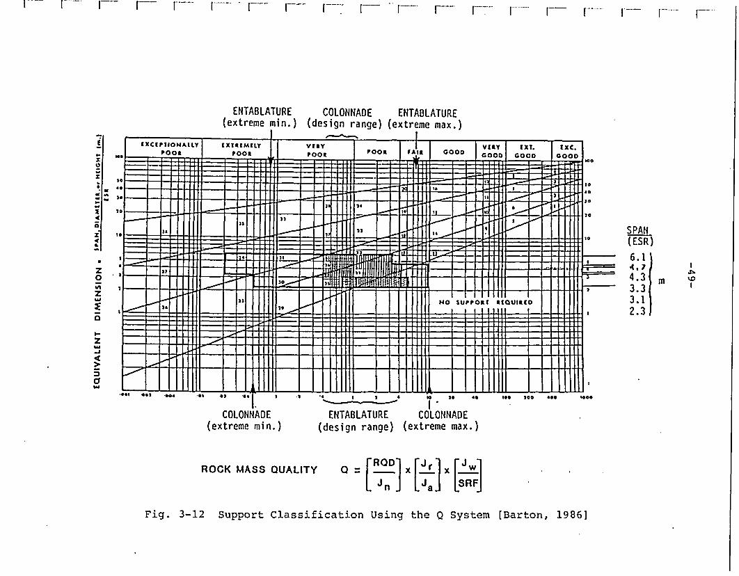
3.2 Geotechnical Classification of Basalt
Barton (1986) has performed a geotechnical classification of theCohassett flow using the Q System. He concluded that the extremedesign values of the Q parameter for the colonnade and entablatureare as follows.
Colonnade 3<Q<14 (ambient conditions)O.5<Q<10 (thermal conditions)
Entablature 0.2<Q<9.3 (ambient conditions)0.08<Q<6.7 (thermal conditions)
These are illustrated in Fig. 3-12 and represent categories in the"extremely poor" to "fair" range. Barton concludes that there maybe a "mild rockburst" problem in the colonnade and high stress(but not rockburst) in the entablature. This is based on the cal-culation of the "stress reduction factor", which is a function ofthe uniaxial compressive strength and major principal stress. Itis not at all clear that rockbursting is strictly a function ofthese two variables; therefore, this classification is untested.
-'-- 1- F - V- I--- r- F r--- r-- W--r- Ir F-- F-- I---- I-- I--
ENTABLATURE COLONNADE ENTABLATURE(extreme min.) (design range) (extreme max.)
-~ ~~~~~~~~~~~~~~~~~~~~ I.
,
of%z
-U
<1II-4
z
w>
I.-zSM
-J
Cy
...I s.f V *~*---
IXCIPTIONALLYPOOR
IXTRIMMLYPOOR I VWAY
POORPOOR %II GOOD
VIRY IXT.COOD COOD
tXC.GOOD
EII
to 1.e.. I I 1 1 1i i1i ' I +
.. F_ - -I I __ i - I I wI 1 1 4-44.4J4-1--44-J-4--J-JI 4-J -.-c: -I4-.-I.JJ. U 2 a4J-.Lh
to
to36
_ j1 24
22_ S I
UHlIHIIIIG i _
SPAN(ESR)
6.1
433 m3.33.12.3
- 1 111 II tlX.0%DILUU = - I I 1 1111] I :-
I21 l I 1111 NOI III
SUPPORTI I I I
RMUIRIO I
Iv _
.I_ - * -.------ 4t--- 4-_
I I I
X}E g X 11I 111111111.... .. a *A4 .. 02 .. .-
COLONNADE(extreme min.)
S 2 4 14 20~~~~~~t '0a
ENTABLATURE COLONNADE(design range) (extreme max.)
we 200 400 woo
ROCK MASS QUALITY a =[ROD] X[ŽJr]
Fig. 3-12 Support Classification Using the Q System [Barton, 1986]
-50-
4.0 ROCKBURST POTENTIAL AT BWIP
As has been discussed, a rockburst can result from several differ-ent phenomena, including shear fracture propagation, slip alongexisting fault planes, and explosive failure of isolated pillarsor blocks of material. Blake (1984) examined the potential forrockbursting at BWIP. He concluded that the potential for burst-ing will be low as a result of the extensive jointing of the rockmass, resulting in stable yield, as well as the low extractionratio. While these are true to a certain extent, the substantialincrease in induced stresses resulting from thermal expansion isignored. In addition, the stabilizing effects of the tight heal-ing and interlocking of joints to which great attention is paid byBarton (1986) and Hoek (in Kim et al, 1986) is ignored in thesediscussions. The following sections describe the rockburstingpotential for various component excavations of the repository.
4.1 General Rockbursting Factors at BWIP
The primary driving factors for rockbursting are, in general, highstresses, brittle rock and some structure(s) to localize deforma-tion. In this section, each of these factors are examined forBWIP.
4.1.1 In-Situ Stresses
The in-situ stress state at Hanford is at the top end of the mea-sured world-wide range for the particular depth of the Cohassettflow. Rockbursting appears to require both high magnitude andhigh stress deviations to occur. The magnitudes of the horizontalmaximum principal stress, a1m5x 70 MPa, is easily within therange of comparable areas withRin which rockbursting is common-place. High stress deviations (i.e., 2.5 or more:1) are also pre-sent at BWIP.
The order of magnitude of stress concentrations around the ellip-tical emplacement rooms prior to thermal loading can be determinedfrom a simple elastic analysis. Examine the problem of an ellip-tical hole in a biaxial stress field:
-51-
The solution to the stress concentrations at the roof and wall aregiven by Hoek and Brown (1980):
Groof = Pz tk (1 + 2H/W) - 1]
where Pz = 24.2 MPa
k = 1.45-3 (extreme case of GHmax = 72.9 MPa)
H/w = 1/2
Because, in the waste panels, the emplacement rooms are separatedby over three drift diameters, there will be little interactionand the solution for a single opening is sufficient.
Therefore, GroQf - 46 MPa to 121 MPa, depending on the orientationof the drift with respect to the principal horizontal stresses.The upper limit of these stresses approaches the peak designstress of 151.2 MPa established by RKE/PB (1985).
As a rough estimate of the thermally-induced stresses, RKE/PB(1985) has determined that adding a far-field horizontal stresscomponent of 40 MPa will produce an equivalent thermally-inducedpeak stress concentration at the roof. Although this estimationis suspect, it is used here as a simple means of estimating thetotal stress to be experienced during the pre-closure period.Again, using the elastic analyses given earlier, the additionalthermal stress concentration (for the maximum range of in-situstresses) is:
Groof (total) = Pz [4.65 (1 + 2*1/2) - 1)
- 24.2 * (8.3)
- 200 MPa
This stress level is greater than the design yield criteria (151MPa) established by RKE/PB (1985).
In the shaft pillar area and the panel entry areas, the driftingresults in a significant number of intersections (Fig. 4-1).There are many points at which these drifts intersect at rela-tively close intervals. The stress concentrations at these pointswill be very high, although the exact level is unknown due to thecomplex, three-dimensional geometry of the drifts.
-52-
fT1PCAL TL. ENM~
Fig. 4-1 Plan View of the Intersections of PanelEntry (Note that, at some locations, 3drifts intersect at one location)
-53-
4.1.2 Material Inhomogeneity
A major cause of rockbursting discussed previously is the inhomo-geneity of the host rock mass. In particular, rockbursts havebeen related to stress concentrations resulting from the intersec-tion of a heading with a fault, dike, beds, or layers of highlycontrasting stiffness or other excavations (Ortlepp, 1983). Theinhomogeneity tends to "localize" failure at a point in the body,resulting in localized instabilities.
Along horizontal planes within the Cohassett flow, the primary in-homogeneities to be encountered include faults, boundaries withintraflow structures, and gas tube structures. Faults are notconsidered to be of major importance in the RRL (Long, 1983), andapparently will not be a major factor contributing to rockburst-ing. The frequency of occurrence of gas tubes or spiracles is re-portedly low-in the RRL (Cross, 1985). The Cohassett flow dips atapproximately 50 across the RRL. Due to the tiered flow struc-ture, the repository excavations will undoubtedly cross many in-traflow boundaries across the 2KM+ plan dimensions of the reposi-tory. The fracture spacing and orientation can change rather dra-matically from colonnade to entablature zones in much the samemanner as crossing a boundary between variable stiffness bedding.In addition, the FEA (Rockwell, 1986) provides the possibility forexcavation within the internal vesicular zone of the Cohassett.The vesicular zone has a reduced stiffness and strength and couldresult in a significant inhomogeneity in stiffness.
4.1.3 Intact Rock Mass Properties
The rock properties discussed earlier indicate that the intact ba-salt is a high strength, brittle rock characterized by explosivefailure in uniaxial compression.
4.1.4 Extraction Ratios
The extraction ratio for a mining pattern is given by the ratio ofthe excavated area to the total area. For the emplacement panels,the extraction ratio for rib pillars is given by Obert and Duvall(1968):
At - AAt
-54-
where At = the total plan area, and
Ap is the pillar area.
By mining standards, this extraction ratio is very low. In fact,the emplacement drifts (= 7m diameter) are placed on roughly 4-diameter centers. Therefore, the emplacement drifts will havelittle effect on one another and will act as isolated headings.
There are locations where the local extraction ratio is very high.For example, at panel entries, up to three drifts intersect, re-sulting in sharp corners (Fig. 4-1). These drift intersectionswill result in a possible rockburst configuration and pose agreater threat during mining.
4.1.5 Evaluation of Rockburst Potential
It has been shown that many of the factors necessary for rock-bursting are present at the Hanford site, including:
(1) high-magnitude stresses;
(2) brittle intact rock mass; and
(3) material inhomogeneity (to some extent).
The greatest questions which remain concern the effects of theheavily-jointed nature of basalt, the relatively low extractionratio, and the effects of thermally-induced stress.
Blake (1984) and Barton (1986) both cite the high frequency injointing as a mitigating factor for rockbursting. It is felt thatthe role of jointing on the stable release of energy and, thus, areduction in the probability of rockbursting is overstated. Theexample of rockbursting in heavily fractured quartzites of theCoeur d'Alene district illustrates that rockbursting can occur inthese cases. In the case of the Coeur d'Alene, yield, apparentlyalong joints, occurs close into the opening, resulting in a yieldzone around the excavation. Rockbursting appears to occur withinthe confined, elastic region outside this zone. Rockbursts arerarely centered directly at the stope (as located by the mine mi-croseismic system)-but at distances of roughly 6 meters or moreinto the wall rock. The resulting damage is primarily the effectof the reflected seismic wave. Additionally, the colonnade maycontain sections of relatively massive, brittle rock. Rockburst-ing appears to be more likely there.
-55-
Low extraction ratio will have an effect on the stress concentra-tions around the emplacement drifts and, thus, the rockburstingfrequency. The driving of the emplacement drifts is analogous tosingle development headings in a mine. As stated previously, thedistance between emplacement drifts ensures minimal interactionand, therefore, the headings may be treated separately. Previouscalculations showed that the stress concentrations existing aroundthe room periphery under ambient conditions will be, for the worstcase, quite close to the design yield stress level determined byRKE/PB (1985). These stresses, however, will likely result inyield on joint surfaces and probably not a pervasive rockburstingproblem. It is quite probable that spalling and some low magni-tude (i.e., <0.5 ML) seismicity will occur during normal driftingin the entablature and colonnade.
Larger magnitude events can occur at intersections of drifts withmaterial inhomogeneities. Intersections with faults, the interiorvesicular zone, or the boundary between entablature and colonnadecould provide a localization mechanism for larger (>0.5 ML)events. Rockbursts of this magnitude are not uncommon in miningof single development or exploratory headings. For example, inthe Coeur d'Alene district, rockbursts commonly occur when drivinghaulage laterals and crosscuts for orebody development. Here, thein-situ horizontal stresses at 5,000 feet depth are roughly thesame as those within the Cohassett flow. Rockbursts often occurat intersections with faults or dikes and can displace severaltons of muck from the roof and walls. The roof has been known tocave for heights of 3 to 5 meters along a fault slip for openingwidths of 3 meters (Fig. 4-2). In fact, Hecla Mining Company nowperforms development blast drilling with drill jumbos rather thanjacklegs-primarily to avoid exposure of the miners to bursting atthe face of headings. Although no major faults have been detectedwithin the RRL (Long, 1983), the Cold Creek Syncline and associ-ated anticlinal and synclinal structures running through it maycontain associated fault structures. The presence of seismicityassociated with these structures (Rohay and Davis, 1983) points tothe fact that slip must be occurring on fracture surfaces atdepth. The presence of instability under the current state ofstress indicates that only small disruptions of the stress stateare necessary to induce failure or slip.
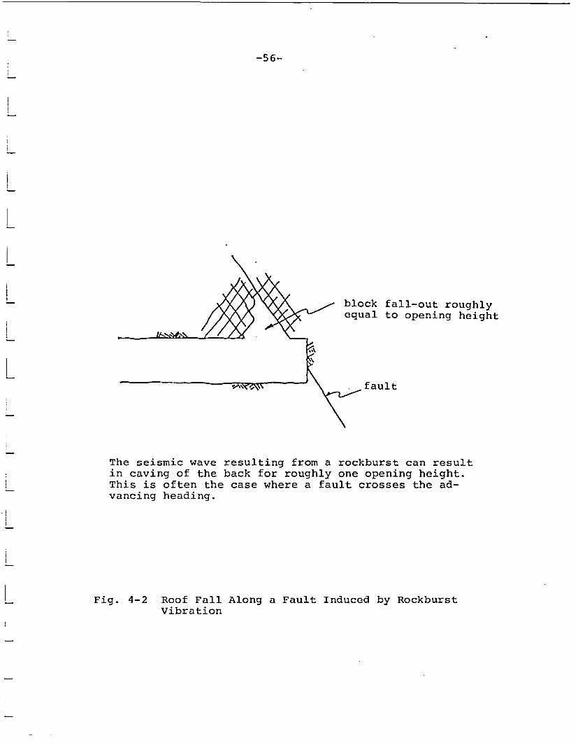
-56-
block fall-out roughly/ X ,- equal to opening height
fault
The seismic wave resulting from a rockburst can resultin caving of the back for roughly one opening height.This is often the case where a fault crosses the ad-vancing heading.
Fig. 4-2 Roof Fall Along a Fault Induced by RockburstVibration

-57-
In a related fashion, the shafts (in effect, a single developmentheading), will cross many boundaries of variable stiffness such asthe dense basalt-brecciated flow top intersection. Rockburstingat the drill bit can be expected to occur at these intersections.Wellbore breakouts will probably occur at east-west shaft loca-tions (900 to GHmax) as the shaft is sunk; the vibrations result-ing from rockbursting may dislodge the material, with the possibleproblem of wedging behind the bit. The photographs shown in Fig.4-3 illustrate wall failure while reaming a 3m diameter raiseboreat the Lucky Friday Mine in Mullan, Idaho. The rock is a brittle,heavily-jointed quartzite under stress conditions similar to theCohassett flow.
Finally, excavation intersections will provide perhaps the mostserious rockburst hazard. In the Coeur d'Alene district, inter-section of the initial levels of cut-and-fill stopes presents oneof the worst rockburst hazards in the mine. These excavationswere converging single headings in "virgin" (i.e., little excava-tion in the near vicinity) ground. Due to the small amount ofprevious excavation, there had been little yield or self-"de-stressing" of the rock mass through sliding on existing joints orpropagation of mining-induced fractures around the drift. Conse-quently, as these drifts converge, the stress concentration canresult in explosive failure of the pillar between headings (Fig.4-4). This failure occurs when the headings are roughly 2-3 diam-eters apart. In the panel entry areas, convergence of up to threedrifts often occurs at one location at acute angles. It is quitepossible that rockbursting may occur here during excavation.These bursts would be characterized by several tons of broken rockbeing displaced from the face of the excavation.
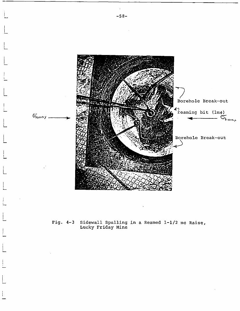
-58-
! Borehole Break-out
4?); reaming bit (lmr)
_q (ahV W (L "Z
Borehole Break-out
1 .
Fig. 4-3 Sidewall Spalling in a Reamed 1-1/2 m4 Raise,Lucky Friday Mine

-59-
yield zones around excavations
burst location inconfined pillar core
Yielding around advancing headings will stress relievethe immediate ground, resulting in bursting in the con-fined rock mass outside this zone.
Fig. 4-4 Rockbursts Occurring at Intersection ofAdvancing Headings
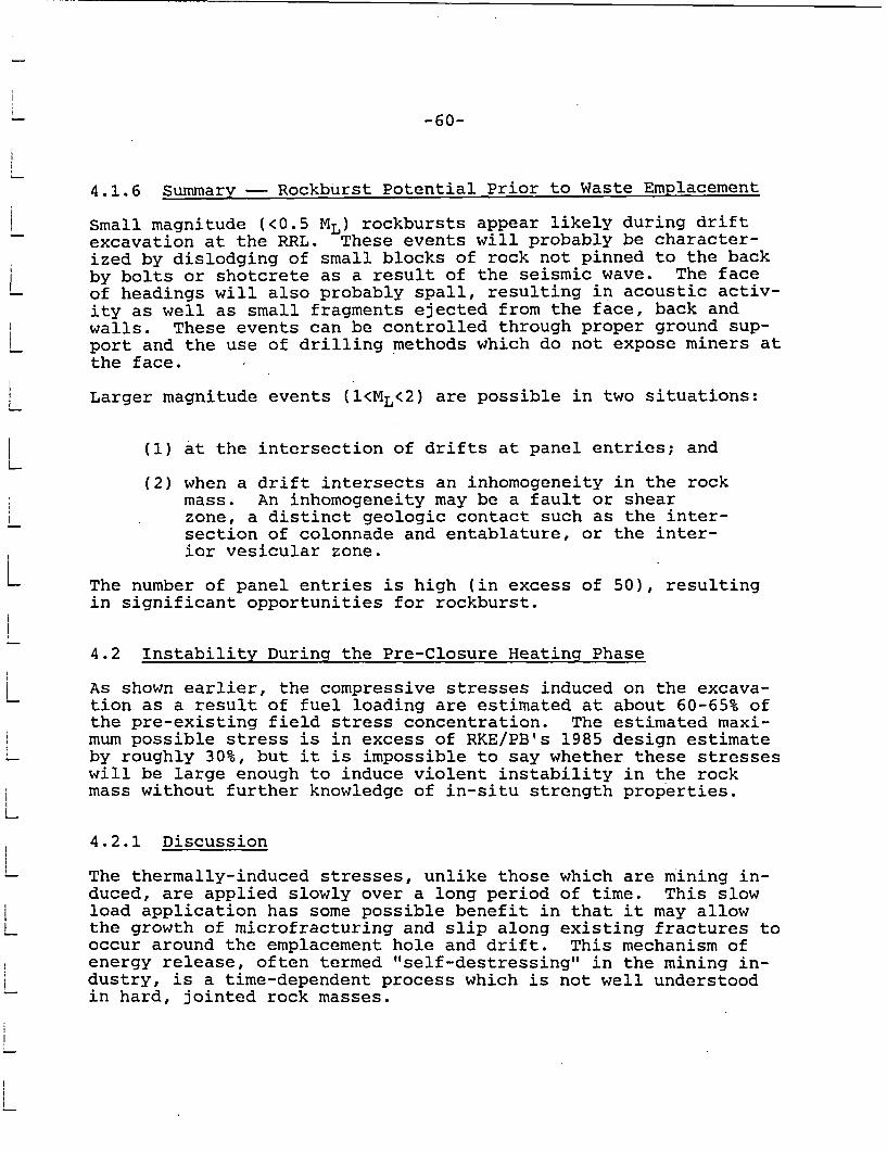
-60-
4.1.6 Summary - Rockburst Potential Prior to Waste Emplacement
Small magnitude (<0.5 ML) rockbursts appear likely during driftexcavation at the RRL. These events will probably be character-ized by dislodging of small blocks of rock not pinned to the backby bolts or shotcrete as a result of the seismic wave. The faceof headings will also probably spall, resulting in acoustic activ-ity as well as small fragments ejected from the face, back andwalls. These events can be controlled through proper ground sup-port and the use of drilling methods which do not expose miners atthe face.
Larger magnitude events (1<ML<2) are possible in two situations:
(1) at the intersection of drifts at panel entries; and
(2) when a drift intersects an inhomogeneity in the rockmass. An inhomogeneity may be a fault or shearzone, a distinct geologic contact such as the inter-section of colonnade and entablature, or the inter-ior vesicular zone.
The number of panel entries is high (in excess of 50), resultingin significant opportunities for rockburst.
4.2 Instability During the Pre-Closure Heating Phase
As shown earlier, the compressive stresses induced on the excava-tion as a result of fuel loading are estimated at about 60-65% ofthe pre-existing field stress concentration. The estimated maxi-mum possible stress is in excess of RKE/PB's 1985 design estimateby roughly 30%, but it is impossible to say whether these stresseswill be large enough to induce violent instability in the rockmass without further knowledge of in-situ strength properties.
4.2.1 Discussion
The thermally-induced stresses, unlike those which are mining in-duced, are applied slowly over a long period of time. This slowload application has some possible benefit in that it may allowthe growth of microfracturing and slip along existing fractures tooccur around the emplacement hole and drift. This mechanism ofenergy release, often termed "self-destressing" in the mining in-dustry, is a time-dependent process which is not well understoodin hard, jointed rock masses.

-61-
The interlocking nature of the joints in basalt, which has beenused by BWIP to support their claim of conservatism of the presentrock support design (Barton, 1986; St. John and Kim, 1986) mayalso lead to a decrease in the ability of the rock mass to releaseenergy non-violently through slippage along existing fracture sur-faces. In addition, the application of shotcrete will further in-hibit yield via joint slip. The relative importance of thesemodes of energy release are not known.
4.2.2 Summary of Rockburst Potential After Waste Emplacement
The probability of rockbursts being induced by the thermal stressconcentrations is unknown. Although the total stress around theexcavation periphery appears to be above the design limit for themost conservative combination of in-situ stresses, it is unlikely,in our opinion, that massive, violent instabilities will occurduring the pre- or post-closure phases. It is our estimate thatthe thermal stresses will induce low level seismicity associatedwith sliding along existing fracture surfaces around the room per-iphery. These instabilities can be contained using bolts withwire mesh and cable slings. There is a greater probability ofsmall events leading to spalling around the emplacement holes dueto the greater confinement afforded by the small hole diameter.The effects of thermal loading on the stability of boreholes mustbe investigated in the ES shaft. The possible role of the engi-neered barriers in maintaining mechanical borewall stability mustbe determined from these tests. Although more difficult to accom-plish in situ, a large-scale thermomechanical investigation ofroom stability in the ES could demonstrate the possibility ofthermally-induced rockbursting or violent failure versus non-violent failure modes. Preliminary ideas regarding such a testare presented in a previous report (Itasca, 1986).
4.3 Preventative Measures for Rockburst Control at BWIP
The standard predictive and preventative measures for rockburstcontrol in mining have been discussed earlier. The application ofthese procedures to BWIP is discussed here.
-62-
4.3.1 Microseismic Monitoring
A real-time microseismic monitoring system at the BWIP site is es-sential. The primary use of the system is to examine the stabil-ity of the rock mass through monitoring of the acoustic output.At the ES site, instrumentation coverage of the headings should bequite simple using a system with less than ten velocity gauges oraccelerometers (single axis is sufficient). In the event that therepository is excavated, coverage of the advance panel emplacementdrifts will be difficult. The difficulty arises from the largeplan area which must be monitored, the mining occurring on onehorizontal plane, and the large amount of extraneous noise gener-ated through drilling and ventilation. Once waste emplacement hasoccurred, a passive monitoring of the stability of the facilityshould continue over time.
As a result of the planar geometry of geophones, event locationsmay be poor. To overcome this problem, mines in South Africawhich have a similar planar array are experimenting with the useof triaxial velocity gauges or accelerometers and using a P-S wavearrival time difference to determine event location (Bawden andKitzinger, 1986). Several smaller plan area systems operating in-dependently may prove to be a better arrangement than one largearray. Various methods undoubtedly will be required to identifythe optimum procedure for locating events.
4.3.2 Destress Blasting
One of the most common techniques for alleviating rockbursts inadvancing headings in U.S. and Canadian mines is to initiate de-stress blast holes in advance of the heading. This procedure wasdiscussed in some detail earlier. The express purpose of thisblasting is to fracture the rock ahead of the face so that it willyield non-violently or to initiate the rockburst in the case thatit is imminent. Deliberately blast-fracturing the host rock massgoes counter to the objectives of the waste management program,which is to disturb the rock mass as little as possible. For thisreason, destress blasting is not viable.
-63-
4.3.3 Opening Design and Rock Support
It has been established that active rockburst control through de-stressing is not feasible. The alternative approach is to designthe openings to minimize stress concentration and to provide ade-quate support of the openings. The present drift design of ellip-tical shape at the approximate ratio of the in-situ stresses tendsto reduce stress concentration around the opening. The spacing ofemplacement drifts is such that little interaction of drifts willoccur. The only design problem we can foresee is the large numberof drift intersections which occur at panel entries. Here, theextraction ratio is rather high (5m wide rooms separated by 13mpillars) with three-drift intersections at 300 angles (Fig. 4-1).Many isolated remnants of roughly lOOm2 cross section (lOmxlOm)are left, as well. This design should be re-examined from thestandpoint of reducing the number of drift intersections and elim-inating acute angle intersections and small remnants.
The present rock support plan calls for untensioned, grouted boltson 0.8m centers plus 5cm fiber reinforced shotcrete in the colon-nade and 5cm fiber reinforced shotcrete in the entablature. Therock support in the colonnade is adequate from the rockburstingstandpoint, but the entablature support should include rockboltingto the face with chainlink fencing to hold loose material shakenfrom the back. In the event that the chainlink is inadequate,wire rope lacing can be used in combination with the chainlink tocontain loose material.
4.3.4 Effects of Rockbursting on Repository Performance andSafety
Depending on the severity of the problem, rockbursting can haverather serious potential effects on repository performance. Thefollowing discussion describes the possible performance effectsfor the various types of rockbursts detailed previously. It mustbe noted that several of these types of instability are not likelyat Hanford and, therefore, the performance effects must be consid-ered hypothetical in nature.
In its most severe form, rockbursting occurs as slip along pre-existing faults or shear zones. As stated earlier, one reason forthe choice of location of the RRL was to avoid the presence offaults; therefore, such a mechanism is not considered likely atHanford. It is important to note, however, that some form offault slippage or dynamic instability is currently taking place atHanford, as indicated by the presence of microearthquake swarms.However, shallow swarm activity apparently does not occur in theRRL. Dynamic slip occurs only on a portion of the fault plane.
-64-
An example of this process is illustrated in Fig. 4-5. Lemos etal (1987), using the distinct element code UDEC, examined theproblem of fault instability occurring from excavation of a planar(longwall) face toward a fault. Slip occurs over a limited sec-tion of the fault between points A and B. The resulting dynamicwave creates a violent velocity "bump" at the surface of the exca-vation. In actual practice, this dynamic wave results in theejection of blocks from the excavation walls. The performance ef-fects are directly related to the area of slip along the faultsince the surfaces of the fault undoubtedly will dilate, enhancingits permeability.
Rockbursting at the face of an advancing excavation (if it occurs)will likely be centered in the elastic, confined rock mass beyondthe yielded skin around the excavation (i.e., at one radius ormore). The problem effects of such an event will be to cause thepropagation of a shear fracture out ahead of the excavation for ashort distance. In South Africa, "burst" fractures have beentraced by mining back along previously-mined panel faces (Ortlepp,1983). These fractures are characterized by a thickness of 100mmor less and are coated by a filling of finely comminuted material.In the case at Hanford, there would seem to be little reason tobelieve that these shear fractures can propagate more than adiame-ter from the tunnel periphery because the extraction ratiois low. The performance effects of a number of shear fractures oflimited extent is felt to be of no greater importance than thefractures already present in the rock mass.
Rockbursts at the face, if sufficiently large (0.5 - 1.0 M ) couldresult in caving of blocky material from the roof, particularly iffaults or shears are present. Such ejection of material createsan obvious safety hazard-not only at the immediate time of theevent but, also, during the barring-down and rebolting procedures.The performance effects of such an event are probably the same asif increasing the dimension of the opening-the "damaged" zonewill be extended to a greater radius proportional to the dimensionof the new opening. The joints within the damaged zone will prob-ably open or dilate as a result of the dynamic wave, possibly re-sulting in more extensive loosened material surrounding the open-ing.
-65-
non-reflectinboundaries
ah-2
(ItE-1)
0.0
0-1.0w(n
-2.0JJ
Uo -3.0
Cu
-4
-2 0
-'L
Quasi-StaticExcavation
Dynamic InstabilityGenerated by Fault Slip
-5.0'
0.5 1.0 1.5 2.0 2.5 (^IE-1)
Time (sec)
Fig. 4-5 A Discrete Element Model of the Dynamic Responseof a Fault Under the Influence of an ApproachingExcavation (The velocity of point C on the roofof the excavation illustrates the velocity pulsegenerated My the dynamic instability of the fault.)

-66-
One area of possible concern surrounding the caving or expulsionof material near the face is the possible connection of the denseinterior of the flow to water-bearing structures such as a gastube, fault, or brecciated interflow zone. It appears highly un-likely that caving could occur in the emplacement panel excava-tions to such an extent that it would connect the repository hori-zon to a flow top. This would require a cave propagation in ex-cess of 15 feet. This is highly unlikely, even in mining withlarge stopes and high extraction ratios. Therefore, interconnec-tion to the flow boundaries should not be considered a major con-cern. Interconnection to a water-filled gas tube or spiracle ispossible from a theoretical standpoint but, again, these struc-tures appear unlikely in the RRL (Long, 1983).
Initial horizontal station excavation from the shaft may provehazardous. The sharp transition in excavation geometry here couldresult in seismicity at or near the brow (Fig. 4-6). In such acase, caving could occur along the interface of the shaft linerand may cause disruption of the water chemical seal ring. Addi-tionally, such caving could cause enhanced groundwater pathways tothe repository horizon. BWIP currently plans to remove the linerfrom the shaft during decommissioning, providing access to the ac-tual wall for sealing purposes. Therefore, the long-term perform-ance effects of a limited caving do not appear to be serious innature.
In conclusion, the possible forms of rockbursting at BWIP would,in the authors' opinion, have relatively local effects on theopening themselves and probably not extending more than a diameteror two into the rock mass. The resulting effects would likely beblocks ejected from the walls and roof, with some possible cavingalong discrete features such as faults or interfaces between flowboundaries. The performance effects of this damage would appearto be similar in nature to those arising from an excavation ofroughly the new dimension-i.e., an extended damage zone and pos-sible enhanced permeability around the openings due to vibration-induced sliding along fracture surfaces. The probability of mas-sive areas of fault slip or propagation of extensive "burst" shearfractures appears to be small, assuming that no faults exist inthe immediate vicinity of the repository.

-67-
water sealring .
shaft ,,= it= 1
_,,,possible burststatilocation
stationstation-brow
- ii= IIl
Fig. 4-6 The Brow at the Shaft Station is ParticularlySensitive to Rockbursting and Must be Exca-vated Carefully

-68-
4.0 CONCLUSIONS
An analysis of the rockburst potential at the Hanford site hasshown the following.
1. Small (<0.5 M ) rockbursts are possible in the faceof advancing Development drifts. Spalling in theface of these headings is possible.
2. Larger (0.5 + ML) rockbursts are possible at the in-tersection of headings entering the emplacementdrifts. The repository design calls for many inter-sections of three drifts at acute angles. It isvery possible that rockbursting could occur as theseheadings converge.
3. In the worst case of emplacement drifts orientednormal to the maximum horizontal stress, the totalroom periphery stress (thermal plus in-situ) appearsto be greater than the design criterion establishedby RKE/PB (1985). Although it is difficult to judgewhether or not this will lead to violent seismicity,it is the opinion of the author that the slow appli-cation of the thermal load will probably result instable yield along joints rather than violent fail-ure of intact rock around the room periphery. Thesudden application of thermal load around the em-placement boreholes could lead to spalling or dis-lodgement of blocks along the hole wall. This canprobably be overcome by proper design of the holelining.
From a practical standpoint, the pre-waste emplacement rockburst-ing problem will be examined during excavation of the'ES facility.It appears necessary that excavation be conducted over a wide planarea so that the effects of intersections with intraflow struc-tures and material inhomogeneities (e.g., faults) can be examined.Also, because the effects of the induced thermal stress from wasteemplacement are unknown, a large-scale heated room test which sub-jects a drift section to expected repository thermal conditionsappears advisable. If rockbursts occur during excavation, it isessential that the performance effects of the burst be examined.First, acoustic emission will provide insight to the volume ofrock which has been affected by the burst. This can be determinedby constructing a three-dimensional picture of the microseismicevents monitored before and after (aftershocks) the rockburst.Other measurements, such as radially-oriented cross-hole permea-bility measurements may provide a quantitative assessment of the
-69-
effects of bursting on performance. Every event which providesobservable damage must be photographed and detailed prior toclean-up. Based on these studies, it may prove prudent to avoidwaste emplacement in areas where rockbursts have occurred.
The effects of rockbursting on performance are difficult to as-sess, since measurements of this type have not been made. It ap-pears that the type of rockburst and the damage that results maybe experienced at Hanford and will be localized to the immediatevicinity of the affected excavation. The performance effects willprobably be limited to induced fracturing within one to two tunneldiameters from the drift periphery. Vibration of the rock mayalso result in sliding and dilation of the fractures, enhancingpermeability. Greater performance effects may occur if excava-tions intersect faults, resulting in limited caving verticallyalong the fault trace. It is not expected that rockburst-inducedcaving will inter-connect the repository horizon with brecciatedinterflow zones.
In conclusion, therefore, rockbursting of the magnitude expectedat Hanford is not expected to cause extensive changes inrepository performance.

-70-
REFERENCES
Barton, Nick. "Rock Mass Quality and Support Recommendations forBasalt at the Candidate Repository Horizon, Based on the Q-System," Rockwell Hanford Operations SD-BWI-ER-012 (Rev. 1),February 1986.
Bawden, W., and F. Kitzinger. "Survey of South African SeismicSystems," Report N-8532, Centre de Recherche Norada, Toronto,Canada, 1986.
Blake, W. "Assessment of the Rockburst Potential in Basalt at theHandord Site," Rockwell Hanford Operations SD-BWI-ER-010, 1984.
Blake, W. "Rockburst Research at the Galena Mine," USBM TPR 39,1971.
Board, M., and S. L. Crouch. "Mine Planning to Control Rockburstsin Cut-and-Fill Excavations," Proceedings of the 16th U.S. Sympos-ium on Rock Mechanics, 1975.
Brady, B. T., and F. W. Leighton. "Seismicity Anomaly Prior to aModerate Rockburst: A Case Study," Proceedings of the 17th U.S.Symposium on Rock Mechanics, 1977.
Caggiano, J. A., and D. W. Duncan, Eds. "Preliminary Interpreta-tion of the Tectonic Stability of the Reference Repository Loca-tion," Rockwell Hanford Operations RHO-BW-ST-19P, 1983.
Cook, N. G. W. "The Design of Underground Excavations," Proceed-ings of the Eighth U.S. Symposium on Rock Mechanics, pp. lB-43B.Minneapolis: University of Minnesota, 1966.
Cook, N. G. W., E. Hoek, J.P.G. Pretorius, W.D. Ortlepp, andM.G.D. Salamon. "Rock Mechanics Applied to the Study of Rock-bursts," J. S. Afr. Inst. Min. Metall., 66, 435-528 (1966).
Cross, R. W. "Probability of Occurrence of Spiracles in CohassettFlow in Repository Layout Area," Rockwell Hanford Operations Com-putational Brief No. 00269, December 18, 1985.
Gendzwill, J. "Induced Seismicity in Saskatchewan Potash Mines,"Rockbursts and Seismicity in Mines (Johannesburg, 1981).
Hanssen, T. H., and A. Myrvang. "Rock Stresses and Rock StressEffects in the Kobbelv Area, Northern Norway," Proceedings of theInternational Symposium on Rock Stress and Rock Stress Measure-ments (Stockholm, September 1986), pp. 625-634. Lulea, Sweden:Centek Publishers, 1986.
-71-
Hedley, D., J. W. Roxburgh, and S. N. Muppalaneiu. "A Case His-tory of Rockbursts at Elliot Lake," Proceedings of the 2nd Inter-national Conference for Stability in Underground Mining(Lexington, Kentucky), 1984.Hoek, E., and E. T. Brown. Underground Excavations in Rock.London: Institute of Mining and Metallurgy, 1980.
Itasca Consulting Group, Inc. "In-Situ Testing at the HanfordSite," report for the U.S. Nuclear Regulatory Commission, July1986.
Karwoski, W., W. McLaughlin, and W. Blake. "Rock Pre-conditioningto Prevent Rockbursts - Report of a Field Demonstration," USBM RI8381, 1979.
Kim, K., S. Dischler, J. Aggson, and M. Hardy. "In-Situ StressesDetermined by Hydraulic Fracturing at the Hanford Site," RockwellHanford Operations RHO-BW-ST-73P, 1986.
Langstaff, J. "Hecla's Seismic Detection System," Proceedings ofthe 17th U.S. Symposium on Rock Mechanics (Snowbird, Utah), 1977.
Lehnhoff, T. F., B. Stefansson, A. F. Topcubasi, and K.Thirumalai. "Stress Ratio Determination from the Core DiskingPhenomenon," Rockwell Hanford Operations, RHO-BW-SA-201 P, August1982.
Lemos, J., R. Hart, and L.Lorig. "Dynamic Analysis of DiscontinuaUsing the Distinct Element Method," to be presented at the 6th In-ternational Symposium on Rock Mechanics (Montreal), 1987.
Long, P. E. "Characterization and Recognition of Intraflow Struc-tures, Grande Ronde Basalt," RHO-BWI-LD-10, September 1978.
Long, P. E., Ed. "Repository Horizon Identification Report -Volume I. Technical Data on Candidate Repository Horizons," RHO-BW-ST-28P, 1983.
Obert, L., and W. Duvall. Rock Mechanics and the Design of Struc-tures in Rock. New York: J. Wiley and Sons, 1967.
Obert, L., and D. E. Stephenson. "Stress Conditions Under WhichCore Discing Occurs," Trans. Soc. Mining Eng., 232(3), 227-235(1965).
Ortlepp, W. D. "The Mechanism and Control of Rockbursts," RockMechanics in Mining Practice, pp. 257-281. Johannesburg: SouthAfrican Int. Min. Metall., 1983.
-72-
Paillet, F. L. "Acoustic Televiewer and Acoustic Waveform LogsUsed to Characterize Deeply-Buried Basalt Flows, Hanford Site,Benton County, Washington," USGS Open File Report 85-419, 1985.
RKE/PB. "Task V, Engineering Study No. 9: Underground RepositoryLayout, Project B-301," Rockwell Hanford Operations SD-BWI-ES-023(Rev. 0), January 1985.
Rockwell International. Final Environmental Assessment, ReferenceRepository Location, Hanford Site, Washington. May 1986.
Rohay, A. C., and J. D. Davis. "Contemporary Deformation in thePasco Basin Area of the Central Columbia Plateau: Preliminary In-terpretation of the Tectonic Stability of the Reference RepositoryLocation," Rockwell Hanford Operations RHO-BW-ST-19P, 1983.
Shepard, J., R. L. Blackwood, and L. K. Rixon. "InstantaneousOutbursts of Coal and Gas with Stresses in Colleries," Rockburstsand Seismicity in Mines. Johanessburg, 1984.
Shepard, J., L. K. Rixon, and L. Griffiths. "Outbursts and Geolo-gical Structures in Coal Mines: A Review," Int. J. Rock Mech.Min. Science, 18, 267-283 (1981)
Spottiswode, S. M., and A. McGarr. "Source Parameters of Tremorsin a Deep-Level Gold Mine," Bull. Seismol. Soc. Am., 65, 93-112(1975).
St. John, C. M., and Kunsoo Kim. "Geoengineering Design Parame-ters Workshop (Proceedings of a Workshop Held in Rapid City, SouthDakota on June 25, 1985), SD-BWI-TI-299, January 1986.
Sublette, W. Rock Mechanics Data Package. Rockwell Hanford Oper-ations SD-BWI-DP-041. April 1986.
Tanton, J. H., T. F. McCarthy, and T. 0. Hagan. "The Introductionof Stabilizing Pillars to Reduce Rockbursts at Western DeepLevels, Ltd.," Rockbursts and Seismicity in Mines. Johannesburg,1984.