mjl technology, ltd. / logic design 메모(technical)달랑 memory만 들어있는 간단한...
TRANSCRIPT

Page 1
메모메모메모메모(Technical) Document No.: MJL-LD-AN-10
Author: 양창우 [[email protected]]
Version: 1.0
Date: 2001년 3월 30일
Subject: LeonardoSpectrum을을을을 사용하여사용하여사용하여사용하여 LPM Function이이이이 사용된사용된사용된사용된 Verilog-HDL Code 합성하기합성하기합성하기합성하기 (APEX 20K/E를를를를 중심으로중심으로중심으로중심으로…)
ALTERA에서 제공하는 LPM Function은 복잡한 Logic을 별다른 노력없이 단시간에 만들수있으며, 또한 일정한 Performance를 제공해주는 잇점이 있다… LPM 자체에 관한 자세한 내용은 ALTERA의 Website (Library of Parameterized Modules (LPM) - http://www.altera.com/products/software/sfw-lpm.html)에서 찾아볼수 있으므로 생략하고 여기에서는 이러한 LPM Function 을 Verilog-HDL 에 어떠한 방법으로 삽입을 할수있는지 그리고 그 Source 를 ALTERA 가 아닌 외부 논리합성툴에서 어떻게 합성을 하는지를 설명한다…
• Target Device는 APEX 20KE로 가정한다…
• LPM Function은 LPM_RAM_DQ를 사용한다…
• Verilog-HDL 합성은 Exemplar Logic사의 LeonardoSpectrum for ALTERA Level1 2000.1b를 사용한다…
• 합성후 생성된 EDIF Netlist를 받아서 Fitting하는 Software는 Quartus II 1.0 + Service Pack 2를 사용한다…
여기서 구현하는 회로는 아래의 Schematic 과 같이 LPM_RAM_DQ 로 구현된 256x8 용량의 Memory 이다… (아래의 그림에서 ram256x8 로 표시되는 부분이 LPM Function 으로 구현된 부분이다…) 달랑 Memory 만 들어있는 간단한 회로를 예로든것은 나중에 Quartus II 를 이용한 Compile 후 실제로 256x8bit Memory 가 APEX 20KE Device 의 ESB (Embedded System Block)에 구현이 되었는지를 쉽게 확인하기 위한 목적도 있다…
MJL Technology, Ltd. / Logic Design

Page 2
기기기기기기기기본본본본본본본본 개개개개개개개개념념념념념념념념
사용자들이 제일 많이 착각을 하는 부분이있다… 다름이 아니라 LPM Function 으로 구현된 부분까지도 논리합성툴을 사용하여 합성을 하는것으로 인식을 하고있다는 것이다… 몇몇사람은 LPM 부분까지 모두 합성을 하여 잘사용하는 중이라고 하는 경우도 있는데, 이건 어디까지나 운이좋아서 된것이지 올바르게 사용했다고는 볼수없다…
일단 가장중요한 개념은 LPM Function 은 합성시 사용되는 것이 아니라 Fitting 시 적용된다는 점이다…
1. 사용자의 Verilog-HDL 구문내에 LPM Function 이 사용되었슴을 알리는 Module 선언부분만이 들어간다… 이것을 논리합성툴을 사용하여 합성을 하면, 합성툴에서는 LPM Function 이 선언 되어있는 부분을 인지하고 Black Box 로 처리해 버린다… (즉, 입출력 Port만 정의하고 내용은 공란으로 처리한다…)
2. 합성이 완료되면 결과물로 EDIF Format의 Netlist가 생성된다… (일반적인 경우…)
3. Netlist 를 사용하여 ALTERA Quartus II 에서 Project 를 생성하고 Compile 을 수행한다… Compile 과정중 합성툴에서 Block Box 로 처리된 부분이 무엇인가 파악하고 LPM Function이라면 이때 관련된 LPM Function의 기능을 추가(구현 - Implementation)한다…
이러한 개념을 가지고 아래의 단계를 진행한다…
MMeeggaaWWiizzaarrdd PPlluugg--IInn MMaannaaggeerr……의의의의의의의의 실실실실실실실실행행행행행행행행
Quartus II를 띄운후 Tools -> MegaWizard Plug-In Manager…를 실행한다… (Figure 1 참조…)
Figure Figure Figure Figure 1111 MegaWizard Plug MegaWizard Plug MegaWizard Plug MegaWizard Plug----In Manager...In Manager...In Manager...In Manager...
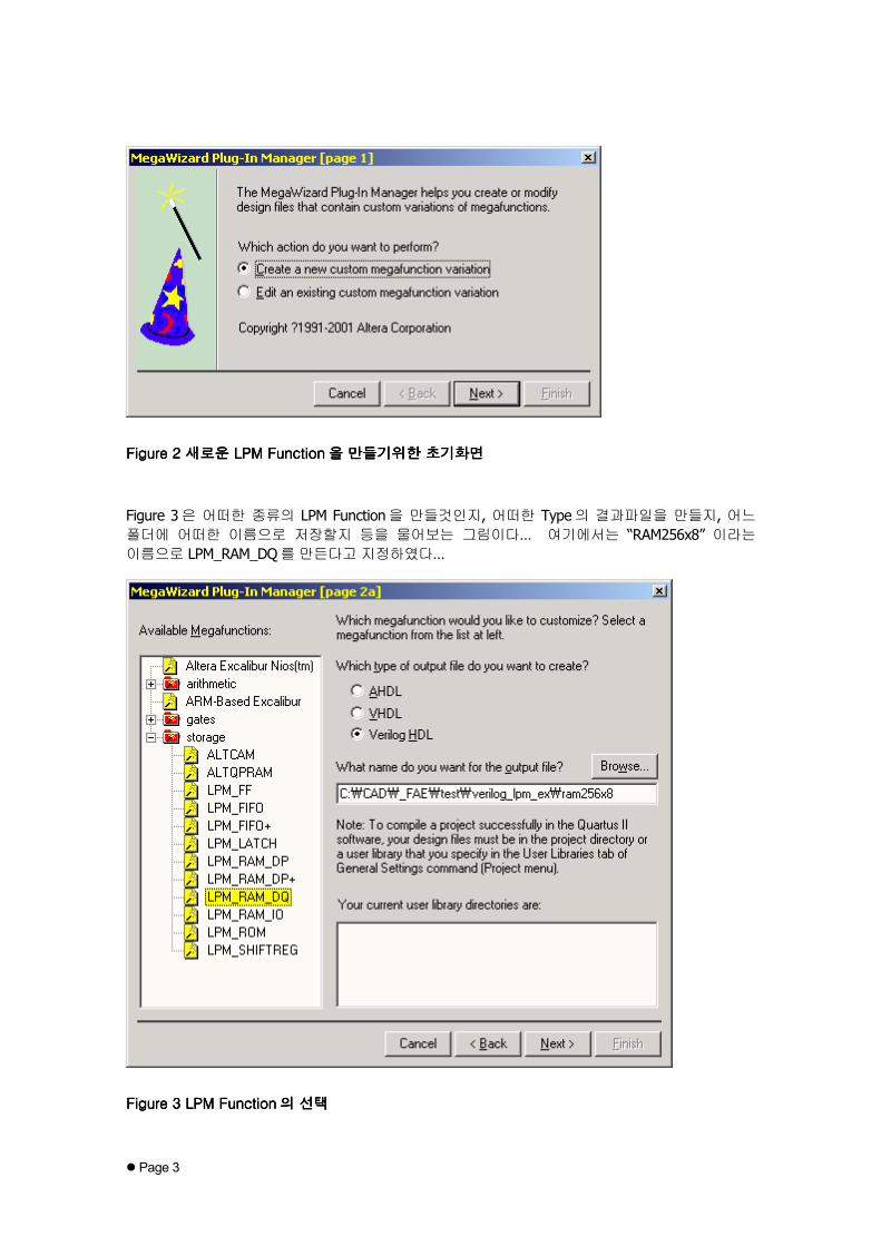
Figure 2 는 MegaWizard Plug-In Manager…의 초기화면이다… 우리는 새로운 LPM Function 을 만들것이므로 “Create a new custom megafunction variation”을 선택하고 다음으로 넘어간다…
Page 3
Figure Figure Figure Figure 2222 새로운새로운새로운새로운 LPM Function LPM Function LPM Function LPM Function을을을을 만들기위한만들기위한만들기위한만들기위한 초기화면초기화면초기화면초기화면
Figure 3은 어떠한 종류의 LPM Function을 만들것인지, 어떠한 Type의 결과파일을 만들지, 어느 폴더에 어떠한 이름으로 저장할지 등을 물어보는 그림이다… 여기에서는 “RAM256x8” 이라는 이름으로 LPM_RAM_DQ를 만든다고 지정하였다…
Figure Figure Figure Figure 3333 LPM Function LPM Function LPM Function LPM Function의의의의 선택선택선택선택

Page 4
우리는 맨처음의 그림에서와 같이 256x8bit Size 의 RAM 을 만들것이므로 LPM_RAM_DQ 를 선택한다… 또한 Verilog-HDL에서 사용할 것이므로 Output File Type은 Verilog HDL로 선택한다… Output File이 저장될 위치는 논리합성툴이 Netlist를 생성해낼 폴더를 지정하면 된다…
그다음으로 나오는 화면은 입/출력 Parameter를 지정하는 화면이다… Figure 4처럼 지정한다…
Figure Figure Figure Figure 4444 입입입입////출력출력출력출력 Parameter Parameter Parameter Parameter의의의의 지정지정지정지정
Figure 5는 지금 만들고있는 RAM Memory의 초기값 지정여부를 묻는 그림이다… LPM_RAM_DQ로 만드는 RAM Memory 가 일반 RAM Memory Device 와 다른점은 여기에 있다… 일반 RAM 은 초기값이 모두 ‘0’이 되지만, LPM 으로 만드는 RAM 은 마치 ROM 처럼 초기값을 넣어줄수가 있는것이다…
만약 초기값을 넣어주려면, “Yes, use this file~~~”를 선택하고 Intel HEX Format이나 ALTERA 자체 Format인 MIF형식으로 작성된 파일을 지정해주면 된다… (두가지 모두 일반 ASCII 형식임…)
화면 하단의 “Implement logic cells only, even if the device contains EABs or ESBs”는 내부 Memory Block이 있는 FLEX 10K나 APEX 20K의 경우 LPM_RAM_DQ를 일반 사용자 Logic이 구현되는 Logic Element를 사용하여 구현하라는 Option인데, 유용성 여부는 사용자 자신의 판단에 달려있다…

Page 5
Figure Figure Figure Figure 5555 Memory Memory Memory Memory내부의내부의내부의내부의 초기값초기값초기값초기값 설정설정설정설정
Figure 6은 MegaWizard Plug-In Manager의 최종화면으로 Finish 버튼을 누르면 지금까지 설정한 값대로 LPM_RAM_DQ Function이 생성된다…
Figure Figure Figure Figure 6666 MegaWizard Plug MegaWizard Plug MegaWizard Plug MegaWizard Plug----In ManagerIn ManagerIn ManagerIn Manager의의의의 최종화면최종화면최종화면최종화면
이상과 같이 작업을 하면 우리가 원하는 256x8bit의 RAM Memory Block이 완성된다… 완성된후 결과 파일이 저장된 폴더를 열어보면 총 6개의 파일이 생성된것을 확인할수 있다…

Page 6
• ram256x8.bsf / ram256x8.cmp / ram256x8.inc / ram256x8.v / ram256x8_bb.v / ram256x8_inst.v
*.bsf 파일은 Schematic작업시 사용되는 Symbol 파일이고, *.cmp 파일은 VHDL Coding시 사용되는 Component 구문이 정의된 파일이며, *.inc 는 AHDL Coding 시 사용되는 Function 이 정의된 파일이다…
*.v 파일들이 실제로 Verilog-HDL로 작업할때 사용되어지는 파일들이다… ram256x8.v는 Quartus II가 Compile시 실제로 참조하는 파일이고, ram256x8_bb.v와 ram256x8_inst.v는 사용자 Verilog-HDL Code에 삽입 되어져야 할 부분이 정의된 파일들이다…
• ram256x8.v 파일…
// megafunction wizard: %LPM_RAM_DQ%// GENERATION: STANDARD// VERSION: WM1.0// MODULE: lpm_ram_dq
// ============================================================// File Name: ram256x8.v// Megafunction Name(s):// lpm_ram_dq// ============================================================// ************************************************************// THIS IS A WIZARD-GENERATED FILE. DO NOT EDIT THIS FILE!// ************************************************************
//Copyright (C) 1991-2001 Altera Corporation//Any megafunction design, and related net list (encrypted or decrypted),//support information, device programming or simulation file, and any other//associated documentation or information provided by Altera or a partner//under Altera's Megafunction Partnership Program may be used only to//program PLD devices (but not masked PLD devices) from Altera. Any other//use of such megafunction design, net list, support information, device//programming or simulation file, or any other related documentation or//information is prohibited for any other purpose, including, but not//limited to modification, reverse engineering, de-compiling, or use with//any other silicon devices, unless such use is explicitly licensed under//a separate agreement with Altera or a megafunction partner. Title to//the intellectual property, including patents, copyrights, trademarks,//trade secrets, or maskworks, embodied in any such megafunction design,//net list, support information, device programming or simulation file, or//any other related documentation or information provided by Altera or a//megafunction partner, remains with Altera, the megafunction partner, or//their respective licensors. No other licenses, including any licenses//needed under any third party's intellectual property, are provided herein.
module ram256x8 (address,inclock,we,data,q);
input [7:0] address;input inclock;input we;input [7:0] data;

Page 7
output [7:0] q;
wire [7:0] sub_wire0;wire [7:0] q = sub_wire0[7:0];
lpm_ram_dq lpm_ram_dq_component (.address (address),.inclock (inclock),.data (data),.we (we),.q (sub_wire0));
defparamlpm_ram_dq_component.lpm_width = 8,lpm_ram_dq_component.lpm_widthad = 8,lpm_ram_dq_component.lpm_indata = "REGISTERED",lpm_ram_dq_component.lpm_address_control = "REGISTERED",lpm_ram_dq_component.lpm_outdata = "UNREGISTERED",lpm_ram_dq_component.lpm_hint = "USE_EAB=ON";
endmodule
// ============================================================// CNX file retrieval info// ============================================================// Retrieval info: PRIVATE: WidthData NUMERIC "8"// Retrieval info: PRIVATE: WidthAddr NUMERIC "8"// Retrieval info: PRIVATE: RegData NUMERIC "1"// Retrieval info: PRIVATE: RegAdd NUMERIC "1"// Retrieval info: PRIVATE: OutputRegistered NUMERIC "0"// Retrieval info: PRIVATE: BlankMemory NUMERIC "1"// Retrieval info: PRIVATE: MIFfilename STRING ""// Retrieval info: PRIVATE: UseLCs NUMERIC "0"// Retrieval info: PRIVATE: DataBusSeparated NUMERIC "1"// Retrieval info: CONSTANT: LPM_WIDTH NUMERIC "8"// Retrieval info: CONSTANT: LPM_WIDTHAD NUMERIC "8"// Retrieval info: CONSTANT: LPM_INDATA STRING "REGISTERED"// Retrieval info: CONSTANT: LPM_ADDRESS_CONTROL STRING "REGISTERED"// Retrieval info: CONSTANT: LPM_OUTDATA STRING "UNREGISTERED"// Retrieval info: CONSTANT: LPM_HINT STRING "USE_EAB=ON"// Retrieval info: USED_PORT: address 0 0 8 0 INPUT NODEFVAL address[7..0]// Retrieval info: USED_PORT: inclock 0 0 0 0 INPUT NODEFVAL inclock// Retrieval info: USED_PORT: we 0 0 0 0 INPUT VCC we// Retrieval info: USED_PORT: q 0 0 8 0 OUTPUT NODEFVAL q[7..0]// Retrieval info: USED_PORT: data 0 0 8 0 INPUT NODEFVAL data[7..0]// Retrieval info: CONNECT: @address 0 0 8 0 address 0 0 8 0// Retrieval info: CONNECT: @inclock 0 0 0 0 inclock 0 0 0 0// Retrieval info: CONNECT: @we 0 0 0 0 we 0 0 0 0// Retrieval info: CONNECT: q 0 0 8 0 @q 0 0 8 0// Retrieval info: CONNECT: @data 0 0 8 0 data 0 0 8 0
• ram256x8_bb.v 파일…
//Copyright (C) 1991-2001 Altera Corporation//Any megafunction design, and related net list (encrypted or decrypted),//support information, device programming or simulation file, and any other//associated documentation or information provided by Altera or a partner//under Altera's Megafunction Partnership Program may be used only to//program PLD devices (but not masked PLD devices) from Altera. Any other//use of such megafunction design, net list, support information, device//programming or simulation file, or any other related documentation or//information is prohibited for any other purpose, including, but not

Page 8
//limited to modification, reverse engineering, de-compiling, or use with//any other silicon devices, unless such use is explicitly licensed under//a separate agreement with Altera or a megafunction partner. Title to//the intellectual property, including patents, copyrights, trademarks,//trade secrets, or maskworks, embodied in any such megafunction design,//net list, support information, device programming or simulation file, or//any other related documentation or information provided by Altera or a//megafunction partner, remains with Altera, the megafunction partner, or//their respective licensors. No other licenses, including any licenses//needed under any third party's intellectual property, are provided herein.
module ram256x8 (address,inclock,we,data,q);
input [7:0] address;input inclock;input we;input [7:0] data;output [7:0] q;
endmodule
• ram256x8_inst.v 파일…
ram256x8 ram256x8_inst (.address ( address_sig ),.inclock ( inclock_sig ),.we ( we_sig ),.data ( data_sig ),.q ( q_sig ));
이글의 앞부분에서도 잠깐 언급을 했듯이 MegaWizard Plug-In Manager 에서 생성된 파일들은 반드시 논리합성툴이 생성해낼 Netlist가 위치할 폴더에 넣어주어야 함을 잊지말아야 한다…
VVeerriilloogg--HHDDLL CCooddiinngg
이제는 사용자 Code 를 작성할 차례이다… 그림을 참고로하여 Coding 을 하면 아래와 같다… 파일명은 lpmramdq_inst.v로 가정한다…

Page 9
• lpmramdq_inst.v 파일…
module lpmramdq_inst(we,clk,a,d,qout
);
input we;input clk;input [7:0] a;input [7:0] d;output [7:0] qout;
ram256x8 ram_inst(.we(we),.inclock(clk),.address(a),.data(d),.q(qout));
endmodule
여기에다가 ram256x8_bb.v의 내용을 복사하여 Source Code의 하단에 붙여넣으면 전체 Source가 완성된다… (Source 중간에 ram_inst 라는 Instance Name 을 가진 ram256x8 Module 이 사용 되었으므로…)
• 완성된 lpmramdq_inst.v 파일…
module lpmramdq_inst(we,clk,a,d,qout
);
input we;input clk;input [7:0] a;input [7:0] d;output [7:0] qout;
ram256x8 ram_inst(.we(we),.inclock(clk),.address(a),.data(d),.q(qout));
endmodule
module ram256x8 (address,inclock,we,data,q);
input [7:0] address;input inclock;input we;input [7:0] data;output [7:0] q;
Page 10
endmodule
LLeeoonnaarrddooSSppeeccttrruumm ffoorr AALLTTEERRAA LLeevveell11 22000000..11bb 를를를를를를를를 사사사사사사사사용용용용용용용용하하하하하하하하여여여여여여여여 합합합합합합합합성성성성성성성성하하하하하하하하기기기기기기기기
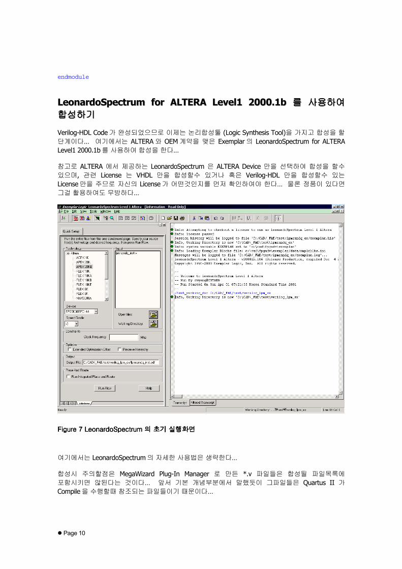
Verilog-HDL Code가 완성되었으므로 이제는 논리합성툴 (Logic Synthesis Tool)을 가지고 합성을 할 단계이다… 여기에서는 ALTERA와 OEM계약을 맺은 Exemplar의 LeonardoSpectrum for ALTERA Level1 2000.1b를 사용하여 합성을 한다…
참고로 ALTERA 에서 제공하는 LeonardoSpectrum 은 ALTERA Device 만을 선택하여 합성을 할수 있으며, 관련 License 는 VHDL 만을 합성할수 있거나 혹은 Verilog-HDL 만을 합성할수 있는 License만을 주므로 자신의 License가 어떤것인지를 먼저 확인하여야 한다… 물론 정품이 있다면 그걸 활용하여도 무방하다…
Figure Figure Figure Figure 7777 LeonardoSpectrum LeonardoSpectrum LeonardoSpectrum LeonardoSpectrum의의의의 초기초기초기초기 실행화면실행화면실행화면실행화면
여기에서는 LeonardoSpectrum의 자세한 사용법은 생략한다…
합성시 주의할점은 MegaWizard Plug-In Manager 로 만든 *.v 파일들은 합성될 파일목록에 포함시키면 않된다는 것이다… 앞서 기본 개념부분에서 말했듯이 그파일들은 Quartus II 가 Compile을 수행할때 참조되는 파일들이기 때문이다…

Page 11
여기에서는 사용자가 작성한 lpmramdq_inst.v만 합성을 하면된다… 여기에서는 반드시 설정해야 할 부분만을 선택하고 합성을 하였다… 선택한 Device 는 EP20K30EFC144-3 이다… 아래는 LeonardoSpectrum for ALTERA Level1 2000.1b에서 출력한 Log이다…
Info: Attempting to checkout a license to run as LeonardoSpectrum Level 1 AlteraInfo: License passedSession history will be logged to file 'C:/CAD/_FAE/test/lpmramdq_ex/exemplar.his'Info, Working Directory is now 'C:\CAD\_FAE\test\lpmramdq_ex'Info: system variable EXEMPLAR set to "c:\cad\fpgadv\exemplar"Info: Loading Exemplar Blocks file: c:\cad\fpgadv\exemplar/data/xmplrblks.iniMessages will be logged to file 'C:/CAD/_FAE/test/lpmramdq_ex/exemplar.log'...LeonardoSpectrum Level 1 Altera - v20001b.106 (Release Production, compiled Dec 42000 at 17:05:11)Copyright 1990-2000 Exemplar Logic, Inc. All rights reserved.
---- Welcome to LeonardoSpectrum Level 1 Altera-- Run By cwyang@CWYANG-- Run Started On Sun Apr 01 07:21:35 Korea Standard Time 2001-- <- 여기까지가여기까지가여기까지가여기까지가 Tool상에서상에서상에서상에서 띄우는띄우는띄우는띄우는 초기초기초기초기 Log이다이다이다이다…->set_working_dir C:/CAD/_FAE/test/verilog_lpm_ex <- 작업폴더작업폴더작업폴더작업폴더 설정설정설정설정…Info, Working Directory is now 'C:\CAD\_FAE\test\verilog_lpm_ex'->_gc_read_init->_gc_run_init->set input_file_list { C:/CAD/_FAE/test/verilog_lpm_ex/src/lpmramdq_inst.v }
<- 합성할합성할합성할합성할 파일파일파일파일 선택선택선택선택…C:/CAD/_FAE/test/verilog_lpm_ex/src/lpmramdq_inst.v->set part EP20K30EFC144 <- Target Device 선택선택선택선택…EP20K30EFC144->set process 3 <- Speed Grade 선택선택선택선택…3->set chip TRUE->set macro FALSEFALSE->set area TRUE->set delay FALSEFALSE->set report briefbrief->set hierarchy_auto TRUETRUE->set hierarchy_preserve FALSEFALSE->set output_file C:/CAD/_FAE/test/verilog_lpm_ex/lpmramdq_inst.edf <-
합성결과물인합성결과물인합성결과물인합성결과물인 Netlist 의의의의 저장경로및저장경로및저장경로및저장경로및 파일명파일명파일명파일명 선택선택선택선택… (기본적으로기본적으로기본적으로기본적으로 Top Design Entity 의의의의 파일명과파일명과파일명과파일명과동동동동일하게일하게일하게일하게 설정된다설정된다설정된다설정된다…)C:/CAD/_FAE/test/verilog_lpm_ex/lpmramdq_inst.edf->set novendor_constraint_file FALSEFALSE->set target apex20eapex20e->_gc_read <- 파일을파일을파일을파일을 Tool내로내로내로내로 불러들여불러들여불러들여불러들여 문법검사와문법검사와문법검사와문법검사와 구문분석을구문분석을구문분석을구문분석을 시작한다시작한다시작한다시작한다…-- Reading target technology apex20eReading library file `c:\cad\fpgadv\exemplar\lib\apex20e.syn`...Library version = 1.6Delays assume: Process=3-- read -tech apex20e { C:/CAD/_FAE/test/verilog_lpm_ex/src/lpmramdq_inst.v }-- Reading file 'C:/CAD/_FAE/test/verilog_lpm_ex/src/lpmramdq_inst.v'...-- Loading module ram256x8-- Loading module lpmramdq_inst-- Compiling root module 'lpmramdq_inst'

Page 12
"C:/CAD/_FAE/test/verilog_lpm_ex/src/lpmramdq_inst.v",line 22: Warning, moduleram256x8 is empty. <- ram256x8 Module이이이이 비었다고비었다고비었다고비었다고 출력하는데출력하는데출력하는데출력하는데, 정상적인정상적인정상적인정상적인 출력결과이다출력결과이다출력결과이다출력결과이다…-- Pre Optimizing Design .work.lpmramdq_inst.INTERFACE-- Boundary optimization.Info: Finished reading design->_gc_run <- 이제부터이제부터이제부터이제부터 Synthesis과정으로과정으로과정으로과정으로 들어간다들어간다들어간다들어간다…-- Run Started On Sun Apr 01 07:25:24 Korea Standard Time 2001---- optimize -target apex20e -effort quick -chip -area -hierarchy=autoUsing default wire table: apex20e_default-- Start optimization for design .work.lpmramdq_inst.INTERFACEUsing default wire table: apex20e_default
est estPass LCs Delay DFFs TRIs PIs POs --CPU--
min:sec1 0 3 0 0 18 8 00:00
Using default wire table: apex20e_default-- Start timing optimization for design .work.lpmramdq_inst.INTERFACENo critical paths to optimize at this level
<- Synthesis Report가가가가 출력된다출력된다출력된다출력된다…*******************************************************
Cell: lpmramdq_inst View: INTERFACE Library: work
*******************************************************
Number of ports : 26Number of nets : 52Number of instances : 29Number of references to this view : 0
Total accumulated area :Number of GND : 1Number of IOs : 26Number of VCC : 1Black Box ram256x8 : 1 <- ram256x8 Module 이이이이 Block Box 로로로로처리되었슴을처리되었슴을처리되었슴을처리되었슴을 나타낸다나타낸다나타낸다나타낸다…
***********************************************Device Utilization for EP20K30EFC144***********************************************Resource Used Avail Utilization-----------------------------------------------IOs 26 92 28.26%LCs 0 1200 0.00%Memory Bits 0 24576 0.00% <- Memory Bits 의의의의 사용량이사용량이사용량이사용량이 “0”으로으로으로으로나오는게나오는게나오는게나오는게 당연하다당연하다당연하다당연하다… Black Box 로로로로 처리되었으므로처리되었으므로처리되었으므로처리되었으므로 LeonardoSpectrum 은은은은 ram256x8 이이이이 무엇인지무엇인지무엇인지무엇인지모르기모르기모르기모르기 때문이다때문이다때문이다때문이다…
-----------------------------------------------Critical Path Report
Critical path #1, (unconstrained path)NAME GATE ARRIVAL LOAD------------------------------------------------------------------------------d(0)/ 0.00 0.00 up 1.49d(0)_ibuf/combout apex20_io_input_none_from_pin 3.13 3.13 up 1.49ram_inst/data(0) GENERIC_BLACK_BOX 0.00 3.13 up 0.00data arrival time 3.13
data required time not specified

Page 13
------------------------------------------------------------------------------data required time not specifieddata arrival time 3.13
----------unconstrained path
------------------------------------------------------------------------------
-- Design summary in file 'C:/CAD/_FAE/test/verilog_lpm_ex/lpmramdq_inst.sum'-- Saving the design database in C:/CAD/_FAE/test/verilog_lpm_ex/lpmramdq_inst.xdb-- Writing file C:/CAD/_FAE/test/verilog_lpm_ex/lpmramdq_inst.xdb-- Writing XDB version 1999.1-- Writing file C:/CAD/_FAE/test/verilog_lpm_ex/lpmramdq_inst.edfInfo, Writing xrf file 'C:/CAD/_FAE/test/verilog_lpm_ex/lpmramdq_inst.xrf'-- Writing file C:/CAD/_FAE/test/verilog_lpm_ex/lpmramdq_inst.xrfInfo, Writing batch file 'C:/CAD/_FAE/test/verilog_lpm_ex/lpmramdq_inst.tcl'-- CPU time taken for this run was 1.81 sec-- Run Successfully Ended On Sun Apr 01 07:25:26 Korea Standard Time 20010Info: Finished Synthesis run <- logic Synthesis가가가가 정상적으로정상적으로정상적으로정상적으로 종료됨종료됨종료됨종료됨…
논리합성이 정상적으로 되면 작업폴더에 lpmramdq_inst.edf 라는 EDIF Format 의 Netlist 가 생성되어 있슴을 확인할수 있다…
QQuuaarrttuuss IIII를를를를를를를를 사사사사사사사사용용용용용용용용하하하하하하하하여여여여여여여여 CCoommppiillee하하하하하하하하기기기기기기기기
현재 작업폴더를 확인하면 MegaWizard Plug-In Manager를 사용하여 생성한 RAM256x8 Module과 LeonardoSpectrum 으로 만든 LPMRAMDQ_INST.EDF 파일이 있을것이다… 이번 단계는 마지막 단계로 ALTERA 에서 제공하는 APEX 20KE Device 용 Compile Tool 인 Quartus II 를 사용하여 Compile을 진행하는 단계이다…
Quartus II를 띄운후 File -> New Project Wizard…를 선택하여 새 Project를 만든다… Figure 8은 New Project Wizard의 초기화면이다… 다음으로 넘어간다…

Page 14
Figure Figure Figure Figure 8888 New Project Wizard New Project Wizard New Project Wizard New Project Wizard의의의의 초기화면초기화면초기화면초기화면
그다음 화면은 지금 만들려는 Project가 위치할 폴더의 경로와 Project 이름 그리고 현 Project에서 사용될 Top-Level Design Entity 이름을 입력하는 부분이다… 세군데 칸을 모두 채워야 하는데, 가장 편리한 방법은 Project 가 위치할 경로를 물어보는 부분의 Browse 버튼을 눌러 나타나는 Select Directory 대화상자에서 폴더를 찾고 아까 만든 *.EDF파일을 더블클릭하는 것이다… 이렇게 하면 나머지 두개의 빈칸도 자동으로 채워진다…

Page 15
FigFigFigFigure ure ure ure 9999 Project Project Project Project 만들기만들기만들기만들기
Figure 9처럼 모두 채워넣었으면 Finish를 눌러 새 Project 생성작업을 완료한다… 우리는 지금까지 lpmramdq_inst라는 이름을 가진 Netlist를 Top-Level Design Entity로 하는 LPMRAMDQ_INST라는 Project를 만들었다…
이번에 행할 작업은 Project -> EDA Tool Settings…를 선택하여 EDIF Netlist 를 만들때 사용한 논리합성툴을 선택하는 단계이다… (이단계를 무시하고 바로 Compile을 할경우 Compiler가 EDIF Netlist 를 읽어들이면서 자동으로 논리합성툴의 종류를 인식하기는 하지만, 만약의 사태에 대비하여 꼭 Check하는 습관을 들이도록 한다…)
Design entry / synthesis tool: 항목에서 우리가 사용했던 Tool을 선택한다… 우리는 ALTERA전용의 LeonardoSpectrum을 사용했었으므로 “Leonardo Spectrum(Level 1)”을 선택하면 된다… OK 버튼을 눌러 설정을 완료한다…

Page 16
Figure Figure Figure Figure 10101010 Logic Synthesis Tool Logic Synthesis Tool Logic Synthesis Tool Logic Synthesis Tool의의의의 선택선택선택선택
이 이후의 작업은 일반적인 Quartus II 작업순서와 동일하다… Compiler Settings…에서 Target Device를 정해주고 (만약 여기서 정하지 않더라도 Compiler가 자동으로 잡아주기는 한다…) Start Compilation을 시작한다…
여기에서는 LeonardoSpectrum 에서 선택했던 EP20K30EFC144-3 을 선택하고 Compile 과정을 수행한다… (Figure 11, 12 참조…)

Page 17
Figure Figure Figure Figure 11111111 Compiler Settinfs Compiler Settinfs Compiler Settinfs Compiler Settinfs중중중중 Target Device Target Device Target Device Target Device의의의의 선택선택선택선택
Figure Figure Figure Figure 12121212 Start Compilation Button Start Compilation Button Start Compilation Button Start Compilation Button
Page 18
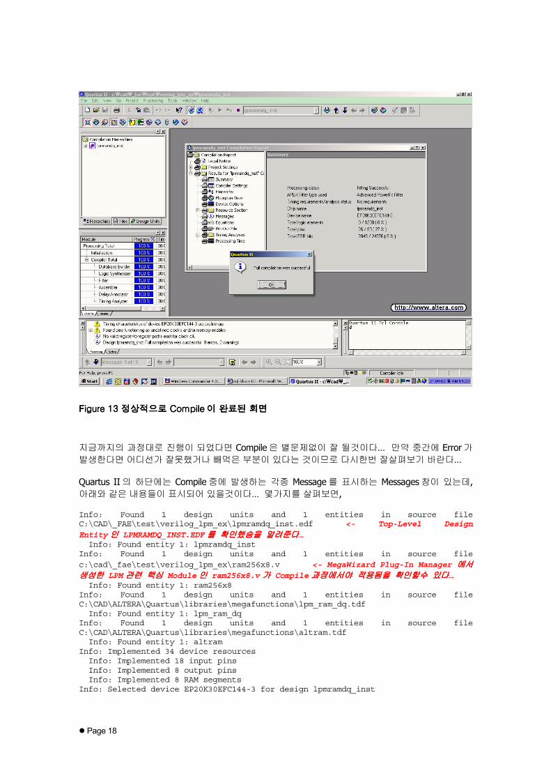
Figure Figure Figure Figure 13131313 정상적으로정상적으로정상적으로정상적으로 Compile Compile Compile Compile이이이이 완료된완료된완료된완료된 회면회면회면회면
지금까지의 과정대로 진행이 되었다면 Compile은 별문제없이 잘 될것이다… 만약 중간에 Error가 발생한다면 어디선가 잘못했거나 빼먹은 부분이 있다는 것이므로 다시한번 잘살펴보기 바란다…
Quartus II의 하단에는 Compile중에 발생하는 각종 Message를 표시하는 Messages창이 있는데, 아래와 같은 내용들이 표시되어 있을것이다… 몇가지를 살펴보면,
Info: Found 1 design units and 1 entities in source fileC:\CAD\_FAE\test\verilog_lpm_ex\lpmramdq_inst.edf <- Top-Level Design
Entity인인인인 LPMRAMDQ_INST.EDF를를를를 확인했슴을확인했슴을확인했슴을확인했슴을 알려준다알려준다알려준다알려준다…Info: Found entity 1: lpmramdq_inst
Info: Found 1 design units and 1 entities in source filec:\cad\_fae\test\verilog_lpm_ex\ram256x8.v <- MegaWizard Plug-In Manager 에서에서에서에서생성한생성한생성한생성한 LPM관련관련관련관련 핵심핵심핵심핵심 Module인인인인 ram256x8.v가가가가 Compile과정에서야과정에서야과정에서야과정에서야 적용됨을적용됨을적용됨을적용됨을 확인할수확인할수확인할수확인할수 있다있다있다있다…Info: Found entity 1: ram256x8
Info: Found 1 design units and 1 entities in source fileC:\CAD\ALTERA\Quartus\libraries\megafunctions\lpm_ram_dq.tdfInfo: Found entity 1: lpm_ram_dq
Info: Found 1 design units and 1 entities in source fileC:\CAD\ALTERA\Quartus\libraries\megafunctions\altram.tdfInfo: Found entity 1: altram
Info: Implemented 34 device resourcesInfo: Implemented 18 input pinsInfo: Implemented 8 output pinsInfo: Implemented 8 RAM segments
Info: Selected device EP20K30EFC144-3 for design lpmramdq_inst

Page 19
Info: Started 1 fitting attempt on Mon Apr 02 2001 at 01:19:44Warning: Timing characteristics of device EP20K30EFC144-3 are preliminaryWarning: Found pins functioning as undefined clocks and/or memory enablesInfo: Assuming node clk is an undefined clock
Info: No valid register-to-register paths exist for clock clkInfo: Design lpmramdq_inst: Full compilation was successful. 0 errors, 2 warnings
이번에는 Quartus II의 Workplace에 있는 lpmramdq_inst Compilation Report의 Summary 부분을 살펴보자…
우리가 작성한 회로는 오직 256x8bit RAM만 들어있는 회로이다… Summary부분을 보면 우리의 예상처럼 Logic Element는 당연히 하나도 사용되지 않았고, 단지 ESB라 불리는 Memory Block만이 2048bit를 쓴것으로 나와있다…
Figure Figure Figure Figure 14141414 Compilation Report Compilation Report Compilation Report Compilation Report
이로써 LPM_RAM_DQ Function을 적용한 사용자 Verilog-HDL이 LeonardoSpecrum의 합성과정을 거쳐 Quartus II Compilation까지 정확하게 이루어 졌슴을 확인할수 있다…
마마마마마마마마치치치치치치치치며며며며며며며며
지금까지 우리는 LPM Function 을 사용한 Verilog-HDL 을 3rd Party Synthesis Tool 인 Leonardo Spectrum 에서 어떨게 합성을 하는지, 그리고 Quartus II 에서는 어떤식으로 Compile 이 이루어 지는지 살펴보았다… 여기서는 Exemplar 사의 Tool 을 가지고 예를 들었지만, 다른 Tool 들을 사용하더라도 공통으로 적용되는 부분이므로 서두에서 언급했던 기본기본기본기본 개념개념개념개념 부분을 잘 숙지하고 작업을 진행한다면 별 문제없이 원하는 결과를 볼수있을 것이다…

Page 20
RReevviissiioonn HHiissttoorryy
2001-3-30 - Ver 1.0: Initialize Release…