mixer manual - massetrecoveryguarding of the mixer shaft below the mixer mounting surface is the...
TRANSCRIPT

MIXER MANUAL
INSTRUCTIONS
INSTALLATION
OPERATION
MAINTENANCE
Customer Name:PO Number:Model:Order Number:Project Number:Tag:
KINEFLOW CORP K2814 X6P50 875318447693Ref PO 004461

INSTRUCTION MANUALLIGHTNIN SALES ORDER 875318
LIGHTNIN PROJECT 447693
TABLE OF CONTENTS
General Arrangement Drawing Safety Check List Assembly Drawing X5P & X6P Operating & Maintenance Instr. A310 (1 piece) Impeller Assembly Bolt Tightening Torques Bolt Tightening Torques 1 Wiring Diagram Spare Parts X5P & X6P US Sales Offices
R447693-A IT-2144 L-17918 IT-5098 L-16701 IT-850 IT-3940 IT-2081 IT-5105 IT-3839
DOCUMENT NO.TITLE


CAUTION -
WARNING -
DANGER -
Revision Date: 5/9/1986
H Revised: 9/9/2011
Signals unsafe practices or hazards which could cause severe personal injury or death.
Signals immediate hazards which will probably cause severe personal injury or death.
This mixer should be equipped with safety or instructional labels similar to those shown below. If any of the labels are missing, damaged or otherwise illegible, DO NOT install, service or operate the mixer. Contact your LIGHTNIN ®representative immediately for instructions.
INST. No. IT-2144
COPYRIGHT © 2011 SPX CORPORATION Page 1 OF 4
EXAMPLES:
Signals unsafe practices or hazards which could cause minor personal injury or property damage.
IMPORTANT: READ THIS SECTION THOROUGHLYSAFETY INSTRUCTIONS / CHECKLIST
IF YOU DO NOT UNDERSTAND ANY PORTION OF THESE INSTRUCTIONS DO NOT ATTEMPT TO INSTALL OR OPERATE THIS MIXER! CONTACT YOUR LIGHTNIN ® REPRESENTATIVE FOR ANY QUESTIONS YOU MAY
HAVE CONCERNING SAFETY OR THESE INSTRUCTIONS.
Your LIGHTNIN ® mixer is equipped with safety labels which contain specific instructions pertaining to the safe handling and operation of the mixer. For your protection, you must understand that failure to follow the safety instructions imprinted on the safety labels or failure to follow the safety instructions printed in this instruction manual may result in serious personal injury or death. In addition, failure to adhere to safety instructions may cause damage to property or equipment.
In this publication, and on the mixer safety labels, the words DANGER, WARNING and CAUTION may be used to signify special instructions to be observed by the installer or user. These instructions warn of potential hazards concerning service, installation or operation if the instructions are performed incorrectly, carelessly or are ignored. Safety instructions alone cannot eliminate the hazards they signal. Strict compliance with these special instructions, along with safe work habits and simple "common sense" are major accident prevention measures.

1.
2.
3.
4.
5.
6.
7.
8.
9.
10.
Date: 5/9/1986
Revised: 9/9/2011
SAFETY CHECK LIST
WARNING: When moving, installing or lifting this mixer, always use equipment which is rated to carry the full load of the mixer. Use only the lifting device, if provided, on your unit to install the mixer. Failure to follow these instructions could cause severe injury, death or damage to property. Consult the appropriate section of this manual for lifting and installation instructions.
WARNING: DO NOT connect the motor to the power source until all components are assembled, the mixer is installed, and all hardware is tightened to the proper torque which is specified in the operation and maintenance manuals supplied by LIGHTNIN ®.
DO NOT operate shaft sealing devices at temperatures higher than those specified in the manual or on the nameplates.
DO NOT service the mixer until you have followed your "Control of Hazardous Energy Sources" (lockout, tagout procedure) as required by OSHA.
IMPORTANT WARNINGS
WARNING: DO NOT attempt to connect a power source to this mixer unless you are licensed or certified to do so. Failure to follow this instruction could cause severe injury, death or damage to property.
All LIGHTNIN ® Mixers and Aerators are provided with properly designed lifting devices and safety covers to avoid potential injury and/or equipment damage. The following SAFETY CHECK LIST should be THOROUGHLY REVIEWED AND ADHERED TO before installing, operating or performing maintenance on the mixer. FAILURE TO FOLLOW THESE INSTRUCTIONS COULD RESULT IN SERIOUS INJURY. Ensure the use of qualified, quality trained and safety conscious personnel.
Revision
H
WARNING: Never attempt to move or adjust a mixer while it is running.
WARNING: Never touch a mixer, which has an electric motor, or any part of an electrical service line cord or conduit, while your hands or feet are wet or if you are standing on a wet or damp surface. Failure to follow this instruction may result in severe electrical shock or death.
DANGER: Never touch any rotating part of a mixer with bare hands, gloved hands or any other part of your body, or with any hand held object. Rotating parts include, but are not limited to, the mixer shaft, impeller(s), set screws, hardware, couplings, mechanical seals and motor fans.
COPYRIGHT © 2011 SPX CORPORATIONINST. No. IT-2144
Page 2 OF 4
WARNING: DO NOT touch any part of mixer that has the potential of having a hot surface including the motor, gear drive housing, seal, shafting and flange. When a mixer is running, the motor temperature rises. This is a normal occurrence, but the motor temperature may be high enough to cause burns to the hands or any other part of the body. DO NOT touch a mixer motor until it cools for at least one hour. Failure to follow these instructions may result in severe personal injury.
WARNING: DO NOT operate mixer for service other than its intended use, that being fluid mixing with the mixer attached to a rigid structure and connected to a power source appropriate to operate the mixer drive motor.

11.
12.
13.
14.
15.
16.
17.
Date: 5/9/1986
Revised: 9/9/2011H COPYRIGHT © 2011 SPX CORPORATION Page 3 OF 4
WARNING: Eye protection must be worn at all times while servicing this mixer. Failure to follow this instructions may result in severe injury or death.
WARNING: Never attempt to clean or service the mixer, or any part of it, while the mixer is running, or while it is connected to a power source. Always turn the mixer off and disconnect the power before cleaning or servicing.
CAUTION: When repairing the mixer, or replacing parts, use factory authorized parts and procedures. Failure to do so may result in damage to the mixer or injury to the user.
DO NOT enter the mixing vessel UNLESS:A. The mixer power supply is locked out (follow item number 5).B. The mixer shaft is firmly attached to the mixer drive or the shaft is supported securely from below.C. You have followed applicable confined space regulations.
Revision INST. No. IT-2144
DO NOT operate mixer until you have checked the following items:A. Make sure the mixer is properly grounded.B. Ensure all protective guards and covers are installed. Guarding of the mixer shaft below the mixer mounting surface is the responsibility of the customer.C. Ensure all detachable components are securely coupled to the mixer.D. Thoroughly REVIEW and ADHERE TO the mixer operating instructions supplied by LIGHTNIN ®.E. Ensure the mixer output shaft rotates freely by hand.F. Ensure all personnel and equipment are clear of rotating parts.G. Ensure all external connections(electrical, hydraulic, pneumatic, etc.) have been completed in accordance with all applicable codes and regulations.
DO NOT make any field changes or modifications (horsepower, seal material components, output speed, shaft lengths, impellers, etc.) without reviewing the changes with your LIGHTNIN ® Sales Representative or the LIGHTNIN ® Customer Service Department.
DO NOT install an aftermarket Variable Frequency Drive without first consulting your LIGHTNIN ® Sales Representative or the LIGHTNIN ® Customer Service Department to determine the compatibility of the existing motor with the Variable Frequency Drive.
SAFETY CHECK LIST, cont'd.
IMPORTANT WARNINGS, cont'd.

5152606 5501523 6517233 6860474 7168848 7387431 75501205152934 5511881 6517246 6877750 7168849 7407322 75721125203630 5568975 6742923 6986507 7278799 7473025 77269465344235 5779359 6746147 7001063 7328809 7481573 77532155368390 5925293 6789314 7056095 7329065 7488137 78747195470152 5988604 6796707 7114844 7331704 75070285480228 6158722 6796770 7168641 7384551 7547135
Revision Date: 5/9/1986
H Revised: 9/9/2011
CAUTION: When applicable specific markings required by Pressure Equipment Directive 97/23/EC (PED) and/or Equipment for Use in Potential Explosive Atmospheres Directive 94/9/EC (ATEX) will be indicated on supporting nameplates. If there is any doubt relating to the intended use of this equipment please contact LIGHTNIN® before installation and operation.
PATENTS
ENVIRONMENTAL NOTICE
Dispose of equipment responsibly at the end of its service, in accordance with local laws and directives. Correct disposal is the responsibility of the end user. If in doubt, consult with local environmental agencies for advice on the best method of disposal.
CE COMPLIANCE
COPYRIGHT © 2011 SPX CORPORATION Page 4 OF 4
If the mixer nameplate has a CE marking on it, then the equipment furnished conforms to the following directives:
Machinery Directive: 2006/42/ECElectro-Magnetic Compatibility: 2004/108/ECLow Voltage Directive: 2006/95/EC
Any CE marking and/or associated documentation applies to the mixer only. This has been supplied on the basis that the mixer is a unique system. When the mixer is installed, it becomes an integral part of a larger system which is not within the scope of supply and CE marking is the responsibility of others.
INST. No. IT-2144
Heavy Series: S10, 70/80, 500/600 - maximum 85 dBA @ 1 meter.
THIS PRODUCT MAY BE COVERED BY ONE OR MORE OF THE FOLLOWING U.S. PATENTS:
NOISE LEVELSSOUND PRESSURE LEVELS
Portable Series: ECL, EV - maximum 80 dBA @ 1 meter.
Noise: 2000/14/EC

HEX HEAD CAP SCREW
RING GEAR RETAINING PIN
THRUST WASHER (NOT SHOWN)NEEDLE BEARING
PLANET DOWEL PIN
IMPELLER SHAFT
PART NAME
AND MIXER SERIAL NUMBER.DRAWING NO., PART NAME, ITEM NO.,WHEN ORDERING PARTS, SPECIFY:
GEAR CARRIER ASSEMBLY
RETAINING WASHER
13
37
ITEM
42
4041
38
24
3536
34
1517
14
BALL BEARINGOIL SEAL (2)VIBRATION PADBALL BEARING
CARRIER BODYCLAMP PAD
CHUCK GRIPLIMIT PINHOUSING
COIN
4
8
1112
9
57
23
1
RETAINING RINGCHUCK SCREWSUN GEARPLANET GEAR
RING GEAR
116
LOCK WASHER68
PLAIN WASHERPLAIN WASHERRETAINING RINGTRAVELER PLATECLAMP SCREWCLAMPHEX NUTDRIVE COUPLING ASSEMBLYGASKETMOTORWORM GEAR CLAMPSHAFT GUARD
116
ITEM
125121119118
1151141101081019897
PART NAME
115
HEX HEAD CAP SCREWSOCKET HEAD CAP SCREWRETAINING RING (2)RETAINING RINGCUP PLATERETAINING RING (2)DRIVE SHAFTCLAMP ASSEMBLYSET SCREW
IMPELLER
5150
56
6067
59
5253
4544
50
118125
17
340
119
4
OPTIONAL CUP PLATE ASSEMBLY(REPLACES ITEMS 115, 116, 118, 119 & 125)
GEAR CARRIER ASSEMBLYAND RING GEAR
14
24
SALES DATA BOOK
DRIVE FLAT
11
1
114
121
9
38
2
5
60
13
15
53
SEC.: 0.42
59
42
NO USE OR DISCLOSURE THEREOF MAY BE MADE WITHOUT
AND RELATED KNOW-HOW IS CONFIDENTIAL AND THE PROPERTYALL EQUIPMENT DESIGN AND APPLICATION DATA SHOWN HEREIN
WITH ELECTRIC MOTOR
GEAR KIT CONSISTS OF ITEMS 2, 5, 7, 108, 110 AND GEARCARRIER ASSEMBLY ITEMS 9, 11, 12,13,14,15, & 24. KIT ISSOLD AS A SET. INDIVIDUAL ITEMS ARE NOT AVAILABLE.
X6P25, X6P33 & X6P50
X5P25, X5P33 & X5P50
ASSEMBLY DRAWING
DRAWING NO. L-17918E
GEAR DRIVE ECL
ISO 9001
LIGHTNIN
CERTIFIED
2001
C
MIXERS AND AERATORS
OF THE LIGHTNIN GROUP OF COMPANIES.
OUR WRITTEN PERMISSION.
(ITEMS 8, 34 & 35 NOT FURNISHED)
42
NOTE:
1
44
45
SEE
DETAIL "A"
38
97
98
59
41
COUPLING CONSTRUCTION
OPTIONAL
R
68
67
97
51
34
MOTOR HANDLE
56
37
52
52
110
7
36
1 1
108
101
DETAIL "A"
98
35
8
51
PAGE: 1.10 DATE: 05-28-03

REVISION
2002
DATE 12–30–00
REVISED 4–23–08 PAGE 1 OF 13
INST. NO. IT–5098F
© LIGHTNINLIGHTNINMIXERS AND AERATORS
®
OPERATING AND MAINTENANCE INSTRUCTIONSFOR LIGHTNIN� X1P, X5P & X6P SERIES
PORTABLE MIXERSSECTION 1 – INITIAL INSPECTION, SHIPPING ARRANGEMENTS AND STORAGE
1.1 Check the shipping crates and your LIGHTNIN equipment for possible shipping damage. Report any damageimmediately to the carrier and our factory.
1.2 The mixer and impellers are packed together. The impeller shaft, if over 48 inches (1200mm) long, is packedin a separate container.
1.3 Do not remove any protective coatings or wrappings until the mixer is ready to be put into service. If the mixeris to be stored, store only in an indoor, clean, dry location with controlled temperatures of 59° F to 104° F (15° C to 40° C). When gear drive models have been stored for more than one year, the gear lubricant shouldbe replaced (see lubrication instructions). Motor shafts are to be rotated manually every month, at least 10to 15 revolutions.
1.4 For units with electronic tachometer, refer to tachometer instructions.
SECTION 2 – MIXER INSTALLATION AND POSITIONINGWARNING: EYE PROTECTION MUST BE WORN AT ALL TIMES WHILE SERVICING THIS MIXER.2.1 Refer to Installation Drawing for:
a . Proper mixer mounting and location.
b . Proper minimum impeller off–bottom and relative spacing for dual impeller applications.
2.2 All mixers are furnished with shaft guard (97) safety covers to eliminate contact with mixer shaft.
WARNING: DO NOT OPERATE THE MIXER UNLESS THE GUARD IS IN PLACE.
2.3 Lift the mixer from its crate using the motor handle provided (refer to Figure 1). DO NOT LIFT THE UNIT BYTHE SHAFT GUARD. Loosen the clamp screw (116) sufficiently so that the clamp base will engage the tanklip or rim when the mixer is mounted. Set the clamp (115) squarely on the mounting surface so that the clamprests on the lip of the tank if a lip is present. Tighten the clamp screw (116), making sure the traveller plate(118) is parallel to the tank lip when it contacts the tank wall. Using an M8 socket or box wrench, or a 5/16hex wrench, tighten the clamp screw to 40–50 ft–lbs (54–61 N⋅m) so that the mixer is held securely to the tank.DO NOT IMPACT THE WRENCH OR USE AN EXTENSION.
DO NOT LIFT MIXER
POTENTIAL PINCH POINT
FIGURE 1
MOTOR HANDLEBY USING SHAFT GUARD (97)
TRAVELER PLATE (118)
CLAMP (115)
CLAMP SCREW (116)
2.4 Impeller rotation must be according to the arrow on the mixer nameplate.
a . Single phase totally enclosed motors are wired at our factory for correct rotation.
b . All three phase and explosion proof motors must be field wired for proper rotation. If rotation does not agreewith nameplate, reverse any two line leads.
c . Dual voltage motors can be wired for the desired voltage. Refer to the connection diagrams provided onthe motor nameplate and inside the conduit box cover.

REVISION
2002
DATE 12–30–00
REVISED 4–23–08 PAGE 2 OF 13
INST. NO. IT–5098F
© LIGHTNINLIGHTNINMIXERS AND AERATORS
®
2.5 The positioning device of the mixer combines a vertical index on the ball of the housing, and a horizontal indexon the rim of the clamp socket. Mixing positions are established by referencing one index against the other.Figure 2 shows the indexes in D–5 position, a typical setting. To change the mixing position, loosen the hexnut (114), adjust the mixer by its motor handle, and tighten the hex nut.
FIGURE 2 – POSITIONING INDEXES
HOUSING BALL INDEX
CLAMP RIM INDEX
HEX NUT (114)
CLAMP PAD (17)
2.6 The correct position for the mixer will vary in individual cases. Use Table 1 to position the mixer in relation tothe tank diameter and height for normal applications. In operation, some adjustment of position may bedesirable for best results.
MIXING PATTERNBATCH
HEIGHT (Z) TANKDIAMETER (T)
CLAMP RIMINDEX
(HORIZONTAL ANGLE)
HOUSING BALLINDEX
(VERTICAL ANGLE)
NORMAL MIXINGZ/T less than 1 D 5Off–center position
Top to bottom turnoverNo swirling
Z/T greater than 1 D 6
VORTEXINGE 5On–center positionE 6
SWIRLINGF 6Off–center position
Usually vortexing F 7
Z/T less than 1Z/T greater than 1
Z/T less than 1Z/T greater than 1
Swirling and vortexing positions may be useful for surface introduction of solids, liquids or gases.
TABLE 1 – MIXER POSITIONING
SECTION 3 – MOTOR CONNECTIONS3.1 LIGHTNIN Portables are equipped with ball bearing chemical plant motors specifically designed for mixer
service in totally enclosed or explosion proof construction.
a . Constant speed mixers are furnished with LIGHTNIN mixer motors unless otherwise specified.
b . For variable speed mixers with electronic or air driven motors, refer to supplementary instructions for motorcontrol data and connection requirements.

REVISION
2002
DATE 12–30–00
REVISED 4–23–08 PAGE 3 OF 13
INST. NO. IT–5098F
© LIGHTNINLIGHTNINMIXERS AND AERATORS
®
3.2 Single Phase Motors or motors nameplated 1/4 thru 3/4 horsepower:
a . Totally enclosed motors may be furnished with power cords fitted with UL approved three prong groundedplugs suitable for the correct voltage.
b . Explosion proof motors are furnished with a pipe tap connection and suitable leads. A conduit box withinternal switch is available for explosion proof service.
c . All LIGHTNIN single phase motors are equipped with an internal over–temperature device with manualreset. If the thermal trips, wait fifteen (15) minutes and depress the reset button on the motor body. A clickindicates reset.
3.3 Three Phase Motors:
a . All totally enclosed motors are equipped with a conduit box and suitable leads.
b . All explosion proof motors are furnished with a pipe tap connection and suitable leads.
SECTION 4 – MIXER IMPELLER AND SHAFT INSTALLATIONWARNING: EYE PROTECTION MUST BE WORN AT ALL TIMES WHILE SERVICING THIS MIXER.4.1 Position the impeller(s) on the impeller shaft. Refer to the specification sheet for recommended dual impeller
spacing.
a . A100 impeller – “Motor End” is cast on the upper side of the impeller. Figure 3 shows how to determinethe upper face of the impeller in the event the printing becomes illegible. Tighten impeller set screwssecurely. For unusually severe conditions, the shaft should be spotted for the set screws.
b . A310 impeller – The larger wedge shaped portion of the hub body must face up towards the mixer. Thebottom of the hub is stamped “Down”. Refer to Figure 3 for general orientation reference. Tighten impellerset screws securely. For unusually severe conditions, the shaft should be spotted for the set screws.
ROTATION
LEADINGEDGE
LARGE WEDGE SHAPEDPORTION OF HUB MUSTFACE UP.
CONVEX SURFACE
FIGURE 3 – IMPELLER ORIENTATION
”DOWN” STAMPED ONLOWER FACE
A310
CAST LETTERING”MOTOR END” MUSTFACE UP.
LEADING EDGESWEPT BACK
A100
4.2 To install the mixer shaft, back off the chuck screw (8) (refer to Figure 4) as far as the limit pin (35) will allow.DO NOT FORCE. Loosely place the shaft guard (97) and worm gear clamp (98) on the impeller shaft (42).
NOTE: The shaft guard hinge must face the impeller end of the shaft. Make sure the shaft is clean, with noburrs.
Insert the impeller shaft into the chuck bore as far as it will go. Draw up the chuck screw, rotating the shaftslightly back and forth to make sure the chuck grip (34) seats against the flat of the shaft. Tighten the chuckscrew, not exceeding the values listed in Table 2. DO NOT IMPACT THE WRENCH OR USE ANEXTENSION

REVISION
2002
DATE 12–30–00
REVISED 4–23–08 PAGE 4 OF 13
INST. NO. IT–5098F
© LIGHTNINLIGHTNINMIXERS AND AERATORS
®
NOTE: A safety feature is provided by a slight taper in the flat on the impeller shaft. The shaft cannot dropout unless the grip is intentionally released.
FIGURE 4 – CHUCK DETAILS
CHUCK GRIP (34)
CHUCK SCREW (8)
LIMIT PIN (35)
DRIVE SHAFT (51) CHUCK
HousingSize
Lower ShaftDiameter
Torque Valuesft. lbs. / (Nm)
11/2”, 5/8”, 16mm 10 / 14
13/4”, 20mm 19 / 26
5/8” 10 / 14
2 3/4”, 20mm 19 / 262
1”, 25mm 34 / 46
3 7/8”, 1” 34 / 46
TABLE 2 – CHUCK SCREW TORQUE VALUES
4.3 ALTERNATE PROCEDURE FOR UNITS EQUIPPED WITH COUPLING:
Connect the impeller shaft to the drive shaft by bolting the coupling halves together. Use care to preventdamage to the rabbets. Make sure the mating faces are flush and free of debris before torquing the hardware.
4.4 Slide the worm gear clamp and shaft guard onto the housing and tighten the clamp securely.
DO NOT OPERATE THE MIXER UNLESS THE GUARD IS IN PLACE.
SECTION 5 – MIXER OPERATION5.1 This LIGHTNIN mixer is designed for continuous operation, and normally needs no additional maintenance.
5.2 Variable speed units have specified critical speed ranges where the unit should not be operated during drawoff condition or operated in air.
CAUTION: THESE CONDITIONS MUST BE AVOIDED WHEN THE UNIT IS BEING OPERATED WITH AVARIABLE SPEED DRIVE. IT IS ALSO NOT RECOMMENDED TO OPERATE THE MIXER WITHEXTREME VORTEXING OR SURGING OF THE LIQUID BEING MIXED.
5.3 All bolts should be retightened 12 hours after assembly, and at each scheduled shut down thereafter.
5.4 Turn on the mixer. Allow time for the mixing pattern to be established, then make any required adjustmentsof position as outlined in Section 2 of these instructions.
SECTION 6 – LUBRICATION6.1 Your LIGHTNIN mixer has been lubricated at the factory with the correct type and amount of high quality
lubricants. Lubricant cleanliness is protected by properly designed closures.

REVISION
2002
DATE 12–30–00
REVISED 4–23–08 PAGE 5 OF 13
INST. NO. IT–5098F
© LIGHTNINLIGHTNINMIXERS AND AERATORS
®REVISION
2002
DATE 12–30–00
REVISED 4–23–08 PAGE 5 OF 13
INST. NO. IT–5098F
© LIGHTNINLIGHTNINMIXERS AND AERATORS
®
6.2 All mixer bearings are sealed type and are pre–packed with lubricant. Relubrication of these bearings is notnecessary.
6.3 The gear chamber in LIGHTNIN X5P & X6P Series mixers has been factory filled with a grease suitable forambient temperature ranges of –4° F to +122° F (–20° C to +50° C). Under normal operating conditions, thislubricant need not be changed until the unit has been dismantled for some reason. Refer to Table 3 forlubricant specifications.
6.4 Under adverse operating conditions, periodic changes of lubricant may be necessary. Adverse conditions aredefined as operating in very humid, dust laden, chemical atmospheres, or where wide variations in ambienttemperatures occurs. Such adverse conditions can lead to deterioration of lubricant compounds andadditives, and it is recommended that the condition of the grease be checked within six months of start–up.
Refer to Section 9 for instructions on disassembling the gear drive.
NOTE: THE GEAR CHAMBER SHOULD BE FILLED TO 1.0 INCHES (25.4mm) FROM THE TOP OF THEGEAR CHAMBER. ALL O–RINGS SHOULD BE CHECKED FOR INTEGRITY AND REPLACED IF THEYARE DEFORMED, CUT OR DETERIORATED.
TABLE 3 – LUBRICANT RECOMMENDATION & CAPACITY
RECOMMENDED GREASE GEAR HOUSING CAPACITY
STANDARD LBS.FOOD GRADE kg
LIGHTNIN 2.2 1
1.0” (25.4mm)
MODEL
X5P & X6P33–50
3.75 1.7X5P & X6P75–300 SHC 0 HD 0BEL–RAY NO–TOX
STANDARD GREASE (PART NUMBER 293101PSP – 2 LB. CONTAINER) ANDLIGHTNINFOOD GRADE GREASE (PART NUMBER 275255PSP – 14 OZ. TUBE) ARE AVAILABLE.
6.5 CHANGING GEAR LUBRICANT
Standard Grease: Gear sets are initially lubricated at the factory with LIGHTNIN SHC 0 grease. This is theoptimum lubricant. It will give the best performance, and is available from LIGHTNIN. An alternate grease,Mobilith SHC 007 can be used, but assembly and disassembly will be more difficult due to the fluid natureof this grease. Greater care must be taken during assembly and disassembly to ensure the grease remainsin the gear chamber.
Food Grade Grease: Gear sets are initially lubricated at the factory with Bell–Ray No–Tox HD 0 grease. Thisis the optimum lubricant. NO OTHER FOOD GRADE GREASE IS ALLOWED. It will give the bestperformance, with no derate necessary, and is available from LIGHTNIN.
a . Make sure the gear housing is vertical to prevent spillage.
b . Remove all old grease from the gear chamber and wipe the gear chamber clean.
c . Pack the gear chamber with fresh grease (see Table 3). Paddle the grease to fill voids and remove airpockets, rotating the shaft and shaking the housing while paddling.
d . Check for free movement of all components by rotating the drive shaft. If satisfactory, refer to Section 9and complete assembly.
SECTION 7 – PREPARATION FOR DISASSEMBLY AND ASSEMBLY

REVISION
2002
DATE 12–30–00
REVISED 4–23–08 PAGE 6 OF 13
INST. NO. IT–5098F
© LIGHTNINLIGHTNINMIXERS AND AERATORS
®
WARNING: DISCONNECT MOTOR LEADS OR OTHERWISE LOCK–OUT POWER SUPPLY BEFORESERVICING THIS MIXER. EYE PROTECTION MUST BE WORN.NOTE: FOR UNITS WITH ELECTRONIC TACHOMETER, REFER TO TACHOMETER INSTRUCTIONS FORREMOVAL INFORMATION.7.1 GENERAL – LIGHTNIN mixers are precision manufactured and assembled to provide long, trouble free
service when properly maintained. If it becomes necessary to disassemble the unit, careful, precisereassembly is necessary.
Refer to the assembly drawing for location of parts.
Equipment that will be required to service the mixer, in addition to standard mechanics tools, is a rubbermallet, retaining ring pliers, arbor press and torque wrench.
When disassembling the mixer, clean adjacent external surfaces to prevent dirt from entering the housings.
It is recommended that oil seals, O–rings and non–metallic gaskets be replaced when the mixer isdisassembled.
7.2 SEAL REPLACEMENT
New oil seals, O–rings and gaskets should always be used. Drive out all old oil seals and removeaccumulations of sealing compound. When replacing seals:
a . Coat the lips of seals with bearing grease.
b . Install oil seals with the lip facing in the direction indicated on the assembly drawing.
c . Coat the section of the shaft sealing surface with oil. If the oil seal must pass over a keyway, wrap the shaftwith thin paper or tape, coat with grease, and pass the seal over.
7.3 BEARING REPLACEMENT
Inspect the bearings carefully and replace if necessary.
a . Old bearings can be removed with a puller or an arbor press.
b . New bearings can be pressed onto the shafts. Be careful to apply load only to the inner race.
c . Make sure the bearings are tightly seated against the shaft or housing shoulder with no clearance.
SECTION 8 – DISASSEMBLY AND ASSEMBLY OF DIRECT DRIVE UNITSNOTE: FOR UNITS WITH ELECTRONIC TACHOMETER, REFER TO TACHOMETER INSTRUCTIONS FORREMOVAL INFORMATION.
DISASSEMBLY – X1P SERIES:8.1 MOTOR REMOVAL
a . Remove the mixer from the tank.
b . Loosen the worm gear clamp (98) and slide the shaft guard (97) down the impeller shaft (42).
c . Remove the impeller shaft (42) from the drive shaft (51), back off the chuck screw (8) as far as the limit pin(35) will allow. The impeller shaft is now free from the chuck and can be withdrawn.
FOR MODELS EQUIPPED WITH COUPLING: Remove the coupling bolts (67), then remove the impellershaft.
d . Remove the mixer hardware (3, 114 & 121), clamp assembly (50), vibration pad (40) and clamp pad fromthe housing (36).
e . Set the mixer upright on a workbench.
f . X1P33 – 50 electric motor:
Remove the four cap screws (60) holding the motor (101) to the housing (36).
X1P 75 – 300 electric motor:
Remove the four cap screws (155) and washers (62) holding the adapter (103) and electric motor (101)to the housing (36).
g . X1P75 – 300 electric motor:

REVISION
2002
DATE 12–30–00
REVISED 4–23–08 PAGE 7 OF 13
INST. NO. IT–5098F
© LIGHTNINLIGHTNINMIXERS AND AERATORS
®REVISION
2002
DATE 12–30–00
REVISED 4–23–08 PAGE 7 OF 13
INST. NO. IT–5098F
© LIGHTNINLIGHTNINMIXERS AND AERATORS
®
Remove the four flat head screws (60) holding the adapter (103) to the electric motor. Remove the O–ring(109).
h . Lift the motor (101), motor coupling half and motor gasket (108) off the housing.
i . Loosen the set screw, and remove the motor coupling half and key (106).
j . Loosen the set screw, and remove the drive shaft coupling half, coupling insert and key (Item 117 – ModelsX1P75 thru 300 only).
8.2 DRIVE SHAFT & HOUSING DISASSEMBLY
a . Place the housing (36) upright on a workbench and remove the retaining rings (52 & 56).
b . Place the housing upright in a press, and press out the drive shaft (51), bearing (41) and oil seal (38).
c . Remove the upper retaining ring (59) and press or pull the lower bearing (41) off the shaft. Remove the lowerretaining ring (59) and oil seal (38).
d . Turn the housing over and press out the upper bearing (37).
Models X1P33 – 50: Remove the lower retaining ring (52) from the housing (36).
e . Inspect the bearings (37 & 41). Replace if there is excessive wear.
8.3 CHUCK DISASSEMBLY
a . Place a flat blade screwdriver between the limit pin (35) and chuck screw (8), and drive the pin downsufficiently to allow removal with pliers.
b . Remove the chuck screw (8) and chuck grip (34).
ASSEMBLY – X1P SERIES:8.4 PREPARING FOR ASSEMBLY
a . Clean all parts thoroughly.b . Inspect for the following defects:
1 . Cracks or damage of the housing.2 . Dents, gouges or scoring of the drive shaft, housing bore, and particularly the mating faces of the motor
and housing.
c . Repair or replace defective parts. It is good practice to replace an oil seal which has been removed fromthe housing. Apply a small quantity of bearing grease to the housing bore, and around the oil seal lip toprovide lubrication and make the seal more effective.
d . Replace the bearings if they show indications of wear.
8.5 DRIVE SHAFT ASSEMBLY
a . Press the lower oil seal (38) down the drive shaft (51) as far as possible, with the seal cavity facing theretaining ring grooves as shown in Figure 5. Make sure the oil seal has the internal spring removed. Thisis a non–lubricated seal, and will run hot and have a shortened life if the spring is not removed.
FIGURE 5 – OIL SEAL INSTALLATION
HOUSING (36)
BEARING (41)
OIL SEAL (38)SHOWN WITHSPRING REMOVED
DRIVE SHAFT (51)
b . Install the lower retaining ring (59).

REVISION
2002
DATE 12–30–00
REVISED 4–23–08 PAGE 8 OF 13
INST. NO. IT–5098F
© LIGHTNINLIGHTNINMIXERS AND AERATORS
®REVISION
2002
DATE 12–30–00
REVISED 4–23–08 PAGE 8 OF 13
INST. NO. IT–5098F
© LIGHTNINLIGHTNINMIXERS AND AERATORS
®
c . Press the lower bearing (41) onto the drive shaft (51). The bearing must seat against the retaining ring withno visible gap.
d . Install the upper retaining ring (59).
e . For mixers with chuck type drive shaft:
1 . Assemble the chuck grip (34) on the chuck screw (8).
2 . Thread the chuck screw into the chuck (51).
3 . Insert the limit pin (35) so that it is flush with the drive shaft (51) face.
8.6 DRIVE SHAFT AND HOUSING ASSEMBLY
a . Models X1P33 – 50: Install the lower retaining ring (52) in the housing (36).
b . Mount the housing (36) in an arbor press, large end up.
c . Press the bearing (37) on its outer race to the retaining ring (Models X1P33 – 50) or the shoulder of thehousing bore (Models X1P75 – 300).
d . Install the upper retaining ring (52).
e . Support the housing, large end down, by resting the inner race of the bearing on a suitable sleeve.
f . Press the drive shaft (38) into the bearing until the shoulder of the shaft registers against the inner race ofthe bearing.
g . Install the upper retaining ring (56) in the shaft groove.
h . Turn the housing large end down, and adjust the lower oil seal until it is flush with the end of the housing.
8.7 MOTOR COUPLING ASSEMBLY
a . Position the motor coupling hub as shown in Figure 6.
b . Tighten the set screws.
c . Place the drive coupling half and key (Item 117, Models X1P75 – 300 only) onto the drive shaft until itbottoms on the shaft shoulder. Tighten the set screw.
d . Install the coupling insert into the drive shaft coupling half.
MOTOR (101)
MOTOR COUPLING HUB
FIGURE 6 – MOTOR COUPLING PLACEMENT
HUB MUST SIT FLUSHWITH END OF MOTOR SHAFT
8.8 MOTOR ASSEMBLY
a . X1P75 – 300 electric motor:
Install the O–ring (109) in the adapter plate (103) and place them on the motor (101). Secure with the flathead screws (60).
b . Install the motor gasket (108) on the motor (101) (Models X1P33 – 50) or the adapter plate (103) (ModelsX1P75 – 300). A small amount of grease on the motor/adapter mounting face, to hold the gasket in place,and oil on the gasket rabbet will ease motor/adapter to housing assembly.
NOTE: X1P33 – 50 Align the slots in the motor gasket with the motor mounting holes to ensure a leak tightseal.
X1P75 – 300 Align the slots in the motor gasket as shown in Figure 6A to ensure a leak tight seal.

REVISION
2002
DATE 12–30–00
REVISED 4–23–08 PAGE 9 OF 13
INST. NO. IT–5098F
© LIGHTNINLIGHTNINMIXERS AND AERATORS
®
c . Align the motor and the housing so that the switch conduit box (or junction box) of the motor, and the ballof the housing are on the same side.
d . X1P33 – 50: Align the screw holes, install the housing cap screws (60) and tighten evenly.
e . X1P75 – 300: Align the screw holes, install the housing cap screws (155) and washers (62) and tightenevenly.
FIGURE 6A – MOTOR / ADAPTER & GASKET
MOTOR / ADAPTERMOUNTING HOLE
GASKET SLOT
8.9 CLAMP ASSEMBLY
a . Thread the clamp screw (116) through the outer arm of the clamp (115). Slide the plain washer (125) overthe end of the clamp screw. Install the traveler plate (118) so that the four raised surfaces are facing awayfrom the clamp screw. Slide the retaining ring (119) onto the clamp screw. Position the retaining ring toallow free movement of the traveler plate (118).
b . Set the clamp pad (17) in place in the ball of the housing.
c . Install the hex head cap screw (3) in the clamp (115). To keep the cap screw in position, slide the retainingwasher (4) in place on the cap screw.
d . Install the vibration pad (40) in the clamp (115).
e . Pass the hex head cap screw through the slot in the ball of the housing, install the plain washer (121), andloosely thread the hex nut (114) onto the clamp pad.
f . Tighten the hex head cap screw until the clamp can just be moved in the housing ball.
8.10 SAFETY GUARD AND IMPELLER SHAFT ASSEMBLY
a . Loosely place the safety guard (97) and worm gear clamp (98) on the impeller shaft (42).
b . Install the impeller shaft as outlined in Section 4 of these instructions.

REVISION
2002
DATE 12–30–00
REVISED 4–23–08 PAGE 10 OF 13
INST. NO. IT–5098F
© LIGHTNINLIGHTNINMIXERS AND AERATORS
®
SECTION 9 – DISASSEMBLY AND ASSEMBLY OF GEAR DRIVE UNITSNOTE: FOR UNITS WITH ELECTRONIC TACHOMETER, REFER TO TACHOMETER INSTRUCTIONS FORREMOVAL INFORMATION.
DISASSEMBLY – X5P & X6P SERIES:9.1 MOTOR REMOVAL
a . Remove the mixer from the tank.
b . Loosen the worm gear clamp (98) and slide the shaft guard (97) down the impeller shaft (42).
c . Remove the impeller shaft (42) from the drive shaft (51), back off the chuck screw (8) as far as the limit pin(35) will allow. The impeller shaft is now free from the chuck and can be withdrawn.
FOR MODELS EQUIPPED WITH COUPLING: Remove the coupling bolts (67), then remove the impellershaft.
d . Remove the mixer hardware (3, 114 & 121), clamp assembly (50), vibration pad (40) and clamp pad fromthe housing (36).
e . Set the mixer upright on a workbench.
f . X5P, X6P33 – 50 electric motor:
Remove the four cap screws (60) holding the electric or air motor (101) to the housing (36).
X5P, X6P75 – 300 electric motor:
Remove the four cap screws (155) holding the adapter (103) and electric motor (101) to the housing (36).
g . X5P, X6P75 – 300 electric motor:
Remove the four flat head screws (60) holding the adapter (103) to the electric motor. Remove the O–ring(109).
h . Lift the motor (101), motor coupling assembly (102), sun gear (9) and motor gasket (108) off the housing.
i . Remove the sun gear (9) and motor coupling assembly (102).
j . Remove the retaining ring (7), gear carrier assembly (1), ring gear (2), key (Item 27 – Models X5P & X6P200thru 300 only), and any remaining old lubricant.
9.2 DRIVE SHAFT & HOUSING DISASSEMBLY
a . Place the housing (36) upright on a workbench and remove the retaining rings (52 & 56).
b . Place the housing upright in a press, and press out the drive shaft (51), bearing (41) and oil seal (38).
c . Remove the upper retaining ring (59) and press or pull the lower bearing (41) off the shaft. Remove the lowerretaining ring (59) and oil seal (38).
d . Turn the housing over and press out the upper bearing (37).
e . Remove the oil seal (38) from the housing (36).
f . Inspect the bearings (37 & 41). Replace if there is excessive wear.
9.3 CHUCK DISASSEMBLY
a . Place a flat blade screwdriver between the limit pin (35) and chuck screw (8), and drive the pin downsufficiently to allow removal with pliers.
b . Remove the chuck screw (8) and chuck grip (34).

REVISION
2002
DATE 12–30–00
REVISED 4–23–08 PAGE 11 OF 13
INST. NO. IT–5098F
© LIGHTNINLIGHTNINMIXERS AND AERATORS
®
ASSEMBLY – X5P & X6P SERIES:9.4 PREPARING FOR ASSEMBLY
a . Clean all parts thoroughly.
b . Inspect for the following defects:
1 . Cracks or damage of the housing.
2 . Dents, gouges or scoring of the drive shaft, housing bore, and particularly the mating faces of the motorand housing.
c . Repair or replace defective parts. It is good practice to replace an oil seal which has been removed fromthe housing. Apply a small quantity of bearing grease to the housing bore, and around the oil seal lip toprovide lubrication and make the seal more effective.
d . Replace the bearings if they show indications of wear.
9.5 DRIVE SHAFT ASSEMBLY
a . Press the lower oil seal (38) down the drive shaft (51) as far as possible, with the seal cavity facing theretaining ring grooves as shown in Figure 7. Make sure the oil seal has the internal spring removed. Thisis a non–lubricated seal, and will run hot and have a shortened life if the spring is not removed.
FIGURE 7 – OIL SEAL INSTALLATION
HOUSING (36)
BEARING (41)
OIL SEAL (38)SHOWN WITHSPRING REMOVED
DRIVE SHAFT (51)
b . Install the lower retaining ring (59).
c . Press the lower bearing (41) onto the drive shaft (51). The bearing must seat against the retaining ring withno visible gap.
d . Install the upper retaining ring (59).
e . For mixers with chuck type drive shaft:
1 . Assemble the chuck grip (34) on the chuck screw (8).
2 . Thread the chuck screw into the chuck (51).
3 . Insert the limit pin (35) so that it is flush with the drive shaft (51) face.
9.6 DRIVE SHAFT AND HOUSING ASSEMBLY
a . Models X5P, X6P33 – 50: Install the lower retaining ring (52) in the housing (36).
b . Mount the housing (36) in an arbor press, large end up.
c . Press the oil upper seal (38) into the housing (36) with the seal cavity facing the large end of the housing.
d . Press the bearing (37) on its outer race to the shoulder of the housing bore.
e . Install the upper retaining ring (52).
f . Support the housing, large end down, by resting the inner race of the bearing on a suitable sleeve.
g . Press the drive shaft (38) into the bearing until the shoulder of the shaft registers against the inner raceof the bearing.
h . Install the upper retaining ring (56) in the shaft groove.
i . Turn the housing large end down, and adjust the lower oil seal until it is flush with the end of the housing.

REVISION
2002
DATE 12–30–00
REVISED 4–23–08 PAGE 12 OF 13
INST. NO. IT–5098F
© LIGHTNINLIGHTNINMIXERS AND AERATORS
®
9.7 GEAR ASSEMBLY
a . If removed, install the ring gear retaining pins (5).
b . Install the ring gear (2) in the gear housing (21).
c . Install the retaining ring (7) in the groove above the ring gear.
d . PACK THE GEAR CARRIER (1) WITH GREASE and rotate the gears several times to distribute the greaseto the needle bearings (13). Refer to Section 6 of these instructions for lubricant recommendations.
e . X5P & X6P75 thru 150: Align the flats on the inside of the gear carrier (1) with the flats on the drive shaft (51).
f . X5P & X6P200 thru 300: Install the key (27) in the drive shaft (51). Align the keyway in the gear carrier (1)with the keyway on the drive shaft (51).
g . Place the gear carrier assembly onto the drive shaft.
9.8 MOTOR COUPLING ASSEMBLY
a . Assemble the sun gear (9), the drive coupling (110) and key (Item 107 – Models X5P100 thru 300 andX6P100 thru 300 only) until the sun gear shoulders against the drive coupling. Tighten the set screws.
b . Set the elevation of the sun gear to the dimension shown in Figure 8, and tighten the remaining set screws.
SUN GEAR (9)
MOTOR (101)
DRIVE COUPLING (110)
3.87–3.89” (98.43–98.73mm)
FIGURE 8 – SUN GEAR PLACEMENT
ADAPTER (108)
1 SIZE 2 & 3 SIZE
3.98–4.00” (101.2–101.5mm)
c . Fill the gear housing with lubricant to approximately 1 inch (25mm) from the top. Refer to Section 6 of theseinstructions for lubricant recommendations.
9.9 MOTOR ASSEMBLY
a . X5P, X6P75 – 300 electric motor:
Install the O–ring (109) in the adapter plate (103) and place them on the motor (101). Secure with the flathead screws (60).
b . Install the motor gasket (108) on the motor (101) (Models X5, X6P33 – 50) or the adapter plate (103)(Models X5, X6P75 – 300). A small amount of grease on the motor/adapter mounting face, to hold thegasket in place, and oil on the gasket rabbet will ease motor/adapter to housing assembly.
NOTE: X5, X6P33 – 50 Align the slots in the motor gasket with the motor mounting holes to ensure a leaktight seal.
X5, X6P75 – 300 Align the slots in the motor gasket as shown in Figure 6A to ensure a leak tight seal.
c . Align the motor and the housing so that the switch conduit box (or junction box) of the motor, and the ballof the housing are on the same side.
d . X5P, X6P33 – 50: Align the screw holes, install the housing cap screws (60) and tighten evenly.
e . X5P, X6P75 – 300: Align the screw holes, install the housing cap screws (155) and washers (62) and tightenevenly.

REVISION
2002
DATE 12–30–00
REVISED 4–23–08 PAGE 13 OF 13
INST. NO. IT–5098F
© LIGHTNINLIGHTNINMIXERS AND AERATORS
®REVISION
2002
DATE 12–30–00
REVISED 4–23–08 PAGE 13 OF 13
INST. NO. IT–5098F
© LIGHTNINLIGHTNINMIXERS AND AERATORS
®
9.10 CLAMP ASSEMBLY
a . Thread the clamp screw (116) through the outer arm of the clamp (115). Slide the plain washer (125) overthe end of the clamp screw. Install the traveler plate (118) so that the four raised surfaces are facing awayfrom the clamp screw. Slide the retaining ring (119) onto the clamp screw. Position the retaining ring toallow free movement of the traveler plate (118).
b . Set the clamp pad (17) in place in the ball of the housing.
c . Install the hex head cap screw (3) in the clamp (115). To keep the cap screw in position, slide the retainingwasher (4) in place on the cap screw.
d . Assemble the clamp, vibration pad (40) and hex head cap screw (3).
e . Pass the hex head cap screw through the slot in the ball of the housing, install the plain washer (121), andloosely thread the hex nut (114) onto the clamp pad.
f . Tighten the hex head cap screw until the clamp can just be moved in the housing ball.
9.11 SAFETY GUARD AND IMPELLER SHAFT ASSEMBLY
a . Loosely place the safety guard (97) and worm gear clamp (98) on the impeller shaft (42).
b . Install the impeller shaft as outlined in Section 4 of these instructions.


LIGHTNIN
REVISION DATE 2-1-85 LIGHTNIN� �LIGHTNIN INST. NO. IT-850
H REVISED 12-08-11 MIXERS AND AERATORS 2008 PAGE 1 OF 1
BOLT TIGHTENING TORQUE RECOMMENDATIONS Inadequately or improperly tightened hardware can loosen due to vibration or the load reactions imposed by fluid forces. This can result in reduced equipment service life or damage and failure. Recommended torques for tightening ANSI bolts and screws on LIGHTNIN Mixers and Aerators and their mounting structures are listed below for your general reference. These average torque values should be considered only as guides and not as absolute values. The amount of torque required to maintain a tight connection can vary considerably for bolts of the same size under different operating conditions. Variations such as basic joint design, compression factors, type and strength of base and hardware material, surface finish of mating parts and lubrication are only some of the factors that influence the tightness of bolted connections for given bolt torques. UNLESS SPECIFICALLY LISTED ELSEWHERE IN THE DETAILED INSTRUCTIONS, TIGHTEN THE MIXER AND MOUNTING HARDWARE TO THE RECOMMENDED VALUES SHOWN. A torque wrench must be used to ensure compliance with these torque requirements. Certain assembly connections may require special torques that are not listed in the table. These torques can be found in the detailed assembly and disassembly sections of your manual. REVIEW YOUR MANUAL CAREFULLY TO DETERMINE WHERE SPECIAL TORQUES ARE REQUIRED. For severe duty service, torques higher than listed, to tighten a bolt to maximum capacity, can often be used. However, due to the many variables previously mentioned, the only absolute method to determine optimum torque is to deliberately yield a bolt under actual conditions. If a bolt does yield or shear, 75% of the torque applied in yielding the bolt can be used to obtain a tight connection that is satisfactory. ALL BOLTS SHOULD BE RETIGHTENED 12 HOURS AFTER ASSEMBLY, AND AT EACH SCHEDULED SHUT DOWN THEREAFTER.
RECOMMENDED TIGHTENING TORQUES FOR COMMERCIAL GRADE STEEL, GR5, 304 AND 316 STAINLESS STEEL (1) (2)
BOLT THREAD
SIZE
TIGHTENING TORQUES (FT-LBS) (4)
GRADE 2, 3 OR 304/316 SS BOLTS
LUBRICATED
TIGHTENING TORQUES (FT-LBS) (4)
GRADE 5 BOLTS
LUBRICATED
MARKINGGRADE
STEEL SAE GRADE MARKING REFERENCE
GUIDE (2)
1/4 _ 20 4.6 7.2
NO MARK
SAE GRADES 0, 1 AND 2
5/16_ 18 9.6 15
3/8 _ 16 17 26 7/16
_ 14 27 42
SAE GRADE 3 1/2 _ 13 41 64 9/16
_ 12 60 92 5/8 _ 11 83 128
SAE GRADE 5 3/4 _ 10 120 (3) 226 7/8 _ 9 142 (3) 365
1 _ 8 212 547 ALL SOCKET
HEAD CAP SCREWS SAE GRADE 5
11/8 _ 7 301 675 (3)
11/4 _ 7 425 952
13/8 _ 6 557 1249
11/2 _ 6 739 1657
13/4 _ 5 754 (3) 1600 (3)
2 _ 41/2 1134 2406
21/4 _ 41/2 1659 3519 21/2 _ 4 2269 4813
(1) ALL BOLTS SHOULD BE COATED WITH OIL, GREASE OR AN ANTI-SEIZE COMPOUND WHENEVER POSSIBLE. THE THREADS AND BEARING FACE OF BOLT HEADS AND/OR NUTS SHOULD BE LUBRICATED. (2) TORQUE VALUES SHOWN SUPERSEDE PREVIOUS TABLES THAT MAY HAVE ALLOWED LOWER VALUES. IT IS RECOMMENDED THAT ONLY FASTENERS BE USED THAT ARE PROPERLY MARKED, INCLUDING MANUFACTURER’S TRADE MARKING. ONLY FASTENERS MARKED AS SHOWN ARE GUARANTEED TO MEET SPECIFICATION AND PERFORMANCE REQUIREMENTS. (3) ALLOWABLE BOLT STRESS VALUES CHANGE AT THESE LOCATIONS AND IS REFLECTED IN THE SUGGESTED TORQUE VALUES. (4) CONVERSION FACTORS: FRICTION LOCKING DEVICES MULTIPLY LUBRICATED VALUE BY 1.15. THESE TORQUES PERTAIN TO BOLTS OR NUTS WITH FRICTION LOCKING DEVICES SUCH AS NYLON PELLETS OR PATCHES, FIBER INSERTS OR UPSET THREADS. DRY VALUES MULTIPLY LUBRICATED VALUE BY 1.33. METRIC VALUES IN N-m 1FT-LB = 1.3558 N-m

LIGHTNIN
REVISION DATE 6-1-96 LIGHTNIN� �LIGHTNIN INST. NO. IT-3940
F REVISED 08-09-11 MIXERS AND AERATORS 2008 PAGE 1 OF 1
BOLT TIGHTENING TORQUE RECOMMENDATIONS Inadequately or improperly tightened hardware can loosen due to vibration or the load reactions imposed by fluid forces. This can result in reduced equipment service life or damage and failure. Recommended torques for tightening metric bolts and screws on LIGHTNIN Mixers and Aerators and their mounting structures are listed below for your general reference. These average torque values should be considered only as guides and not as absolute values. The amount of torque required to maintain a tight connection can vary considerably for bolts of the same size under different operating conditions. Variations such as basic joint design, compression factors, type and strength of base and hardware material, surface finish of mating parts and lubrication are only some of the factors that influence the tightness of bolted connections for given bolt torques. UNLESS SPECIFICALLY LISTED ELSEWHERE IN THE DETAILED INSTRUCTIONS, TIGHTEN THE MIXER AND MOUNTING HARDWARE TO THE RECOMMENDED VALUES SHOWN IN. A torque wrench must be used to ensure compliance with these torque requirements. Certain assembly connections may require special torques that are not listed in the table. These torques can be found in the detailed assembly and disassembly sections of your manual. REVIEW YOUR MANUAL CAREFULLY TO DETERMINE WHERE SPECIAL TORQUES ARE REQUIRED. For severe duty service, torques higher than listed, to tighten a bolt to maximum capacity, can often be used. However, due to the many variables previously mentioned, the only absolute method to determine optimum torque is to deliberately yield a bolt under actual conditions. If a bolt does yield or shear, 75% of the torque applied in yielding the bolt can be used to obtain a tight connection that is satisfactory. ALL BOLTS SHOULD BE RETIGHTENED 12 HOURS AFTER ASSEMBLY, AND AT EACH SCHEDULED SHUT DOWN THEREAFTER.
RECOMMENDED TIGHTENING TORQUES FOR COMMERCIAL GRADE STEEL, GR5, 304 AND 316 STAINLESS STEEL (1) (2)
BOLT THREAD
SIZE
TIGHTENING TORQUES (FT-LBS) (3)
GRADE 5.6 OR 304/316 SS BOLTS
LUBRICATED
TIGHTENING TORQUES (FT-LBS) (3)GRADE 8.8
BOLTS LUBRICATED
ISO MARKING REFERENCE GUIDE (2)
M5 1.7 4.1 HEX HEAD CAP SSREWS
M6 3.0 7.0
M7 5.0 12
M8 7.0 17
M10 14 34
M12 25 59
M14 39 93 HEX NUT
M16 62 146
M18 85 200
M20 120 284
M22 163 386
M24 207 491
M27 303 718 SOCKET HEAD CAP SSREWS
M30 412 975
M33 561 1327
M36 720 1704
M39 932 2205
M42 1153 2727
(1) ALL BOLTS SHOULD BE COATED WITH OIL, GREASE OR AN ANTI-SEIZE COMPOUND WHENEVER POSSIBLE. THE THREADS AND BEARING FACE OF BOLT HEADS AND/OR NUTS SHOULD BE LUBRICATED. (2) TORQUE VALUES SHOWN SUPERSEDE PREVIOUS TABLES THAT MAY HAVE ALLOWED LOWER VALUES. IT IS RECOMMENDED THAT ONLY FASTENERS BE USED THAT ARE PROPERLY MARKED, INCLUDING MANUFACTURER’S TRADE MARKING. ONLY FASTENERS MARKED AS SHOWN ARE GUARANTEED TO MEET SPECIFICATION AND PERFORMANCE REQUIREMENTS. (3) CONVERSION FACTORS: FRICTION LOCKING DEVICES MULTIPLY LUBRICATED VALUE BY 1.15. THESE TORQUES PERTAIN TO BOLTS OR NUTS WITH FRICTION LOCKING DEVICES SUCH AS NYLON PELLETS OR PATCHES, FIBER INSERTS OR UPSET THREADS. DRY VALUES MULTIPLY LUBRICATED VALUE BY 1.33. METRIC VALUES IN N-m 1FT-LB = 1.3558 N-m

PAGE 1 OF 2© LIGHTNIN
REVISION
1999
DATE 9–30–83
REVISED 12–15–05
INST. NO. IT–2081C
LIGHTNINMIXERS AND AERATORS
®PAGE 1 OF 2
© LIGHTNINREVISION
1999
DATE 9–30–83
REVISED 12–15–05
INST. NO. IT–2081C
LIGHTNINMIXERS AND AERATORS
®
CONNECTION DIAGRAM SINGLE PHASE MOTORS
1
3
5
2
8
4
LINE
1
3
5
2
8
4
LINE
6 LEADS WITHOUT THERMAL PROTECTOR
LOW VOLTAGE HIGH VOLTAGE
2
J
8
1
5
3
LINE
3
5
2
4
LINE
7 LEADS WITH THERMAL PROTECTOR
LOW VOLTAGE HIGH VOLTAGE
4 1
VERIFY PROPER MIXER ROTATION
FIGURE 1 – CONNECTION DIAGRAM
J
8
1
3
5
2
8
4
LINE
1
3
5
2
8
4
LINE
6 LEADS WITHOUT THERMAL PROTECTOR
LOW VOLTAGE HIGH VOLTAGE
2
J
8
1
5
3
LINE
3
5
2
4
LINE
7 LEADS WITH THERMAL PROTECTOR
LOW VOLTAGE HIGH VOLTAGE
4 1
TO REVERSE ROTATION, INTERCHANGE LEADS 5 AND 8
J
8
J
J1
7
8 5
2
96
3
THERMOSTATS CAN BELOCATED IN ANYCOMBINATION OF PHASES
TYPICAL THERMAL CONNECTION IN FULL VOLTAGE STARTERS
STARTSTOP
CRL1 L2CR
J J
LOW VOLTAGE HIGH VOLTAGE
J
J
1
7
2
8
3
9
4
5
6
J
J
1
2
3
4
7
5
8
6
9
THERMOSTATLEADS
THERMOSTATLEADS
L1
L2
L3
TO REVERSE ROTATION, INTERCHANGEANY TWO LINE LEADS
L1
L2
L3
CONNECTION DIAGRAM THREE PHASE MOTORS
FIGURE 2 – CONNECTION DIAGRAM
9 LEADS WITH OPTIONAL THERMAL PROTECTOR
4THERMOSTATS CAN BELOCATED IN ANYCOMBINATION OF PHASES
TYPICAL THERMAL CONNECTION IN FULL VOLTAGE STARTERS
STARTSTOP
CRL1 L2CR
LOW VOLTAGE HIGH VOLTAGE
J
J
1
7
2
8
3
9
4
5
6
J
J
1
2
3
4
7
5
8
6
9
THERMOSTATLEADS
THERMOSTATLEADS
L1
L2
L3
L1
L2
L3
THERMOSTATS CAN BELOCATED IN ANYCOMBINATION OF PHASES
TYPICAL THERMAL CONNECTION IN FULL VOLTAGE STARTERS
STARTSTOP
CRL1 L2CR
LOW VOLTAGE HIGH VOLTAGE
J
J
1
7
2
8
3
9
4
5
6
J
J
1
2
3
4
7
5
8
6
9
THERMOSTATLEADS
THERMOSTATLEADS
L1
L2
L3
L1
L2
L3
ALL XP MOTORS HAVE THERMAL PROTECTION (J)
VERIFY PROPER MIXER ROTATION
PAGE 2 OF 2© LIGHTNIN
REVISION
1999
DATE 9–30–83
REVISED 12–15–05
INST. NO. IT–2081C
LIGHTNINMIXERS AND AERATORS
®
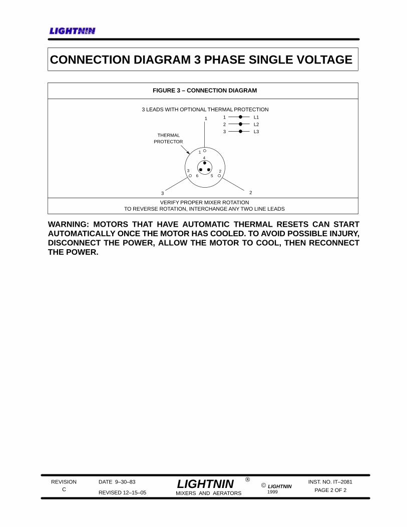
TO REVERSE ROTATION, INTERCHANGE ANY TWO LINE LEADS
3 LEADS WITH OPTIONAL THERMAL PROTECTION1
2
3
L1
L2
L3
1
23
1
236 5
4
THERMALPROTECTOR
FIGURE 3 – CONNECTION DIAGRAM
CONNECTION DIAGRAM 3 PHASE SINGLE VOLTAGE
VERIFY PROPER MIXER ROTATION
WARNING: MOTORS THAT HAVE AUTOMATIC THERMAL RESETS CAN STARTAUTOMATICALLY ONCE THE MOTOR HAS COOLED. TO AVOID POSSIBLE INJURY,DISCONNECT THE POWER, ALLOW THE MOTOR TO COOL, THEN RECONNECTTHE POWER.

MIXER PARTS UNIT SIZE:
ITEMNO.
IDENT.CODE DESCRIPTION
REFER TO DRAWING L--17918
QTY. PART NO. PRICE(EACH)
P CUP PLATE53 1 872264PSP
MOTOR101
GASKET108 1 272671PSP
L CLAMP115 1 872261PSP
C DRIVE SHAFT KIT -- COMPLETE 1 872315PSPCHUCK -- 3/4” DIA. LOWER SHAFT
CONSISTS OF THE FOLLOWING PARTS:
C CHUCK SCREW8 272243174
C DRIVE SHAFT51
R DRIVE SHAFT51 1 272296PD4
R HEX HEAD CAP SCREW67 4 290225316
R LOCKWASHER68 4 290210316
SHIPMENT(WEEKS)
NOTE: See mixer nameplate or spec. sheet for unit size & ratio. See Assembly Drawing for item no. identifier
IDENTITY CODE:
C = Use With Chuck Drive ShaftL = Use With Clamp
Blank code denotes common parts
* Recommended spare parts
X6P25, X6P33, X6P50
P = Use With Cup Plate
C CHUCK GRIP34 1 272240316
C LIMIT PIN35 1 272668420
Contact LIGHTNIN Representative
PARTS PRICING BOOK SECTION: 4 PAGE: 5.00 DATE: 7--31--06
REVISION
PAGE 1
IT--5105F OF 4
For service and repair, call 1--888--MIX BEST (1--888--649--2378)
1 272286PD4
GEAR DRIVEECL PORTABLE
ELECTRIC MOTOR
R = Use With Rigid Coupling Drive Shaft
R DRIVE SHAFT KIT -- COMPLETE 1 872316PSPRIGID COUPLING -- 3/4” DIA. LOWER SHAFT
CONSISTS OF THE FOLLOWING PARTS:
1
R DRIVE SHAFT51 1 272297PD4
R HEX HEAD CAP SCREW67 4 290225316
R LOCKWASHER68 4 290210316
R DRIVE SHAFT KIT -- COMPLETE 1 872317PSPRIGID COUPLING -- 1” DIA. LOWER SHAFT
CONSISTS OF THE FOLLOWING PARTS:
5 = 350 RPM6 = 280 RPM
X5P25, X5P33, X5P50
ITEMNO.
IDENT.CODE DESCRIPTION
CONSISTS OF THE FOLLOWING PARTS:
QTY. PART NO. PRICE(EACH)
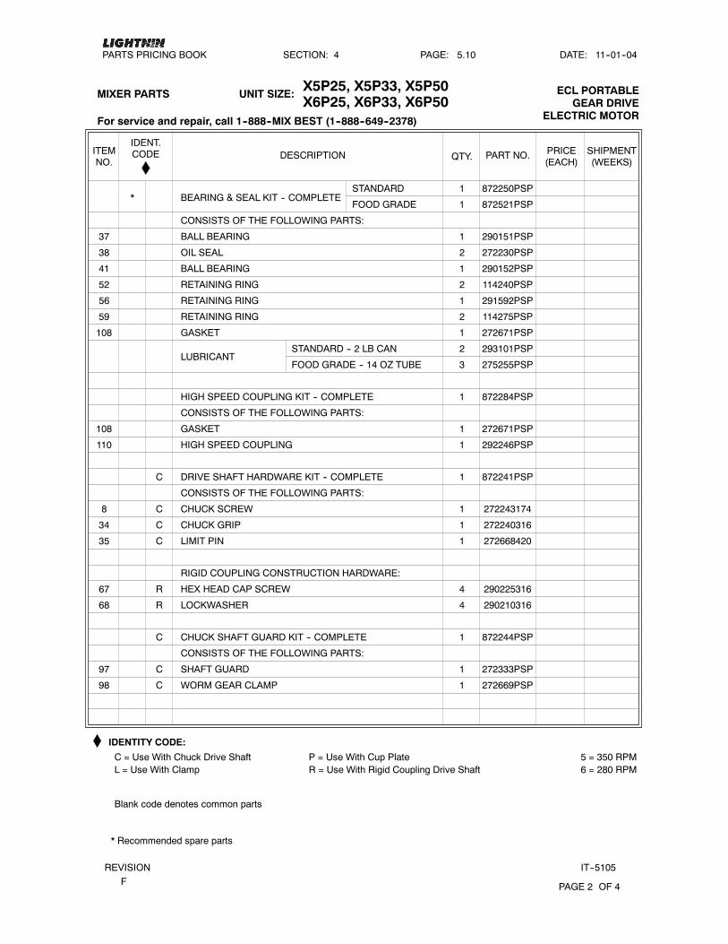
BALL BEARING37 1 290151PSP
OIL SEAL38 2 272230PSP
BALL BEARING41 1 290152PSP
RETAINING RING52 2 114240PSP
RETAINING RING56 1 291592PSP
RETAINING RING59 2 114275PSP
GASKET108 1 272671PSP
LUBRICANT2 293101PSP
HIGH SPEED COUPLING KIT -- COMPLETE 1
CONSISTS OF THE FOLLOWING PARTS:
872284PSP
C DRIVE SHAFT HARDWARE KIT -- COMPLETE
CONSISTS OF THE FOLLOWING PARTS:
C CHUCK SCREW8
C CHUCK GRIP34
272668420
RIGID COUPLING CONSTRUCTION HARDWARE:
R HEX HEAD CAP SCREW67 4
R LOCKWASHER68 4
290225316
290210316
C CHUCK SHAFT GUARD KIT -- COMPLETE 1
CONSISTS OF THE FOLLOWING PARTS:
872244PSP
C WORM GEAR CLAMP98 1
272333PSP
SHIPMENT(WEEKS)
C SHAFT GUARD97 1
C LIMIT PIN35 1
272240316
IDENTITY CODE:
Blank code denotes common parts
* Recommended spare parts
GASKET108 1
HIGH SPEED COUPLING110 1
272671PSP
PARTS PRICING BOOK SECTION: 4 PAGE: 5.10 DATE: 11--01--04
REVISION
PAGE 2
IT--5105F OF 4
For service and repair, call 1--888--MIX BEST (1--888--649--2378)
GEAR DRIVEECL PORTABLE
ELECTRIC MOTOR
* BEARING & SEAL KIT -- COMPLETE1 872250PSP
1 872241PSP
1
1
272243174
292246PSP
C = Use With Chuck Drive ShaftL = Use With Clamp
P = Use With Cup PlateR = Use With Rigid Coupling Drive Shaft
272669PSP
5 = 350 RPM6 = 280 RPM
MIXER PARTS UNIT SIZE:X6P25, X6P33, X6P50X5P25, X5P33, X5P50
STANDARD
1 872521PSPFOOD GRADE
STANDARD -- 2 LB CAN
FOOD GRADE -- 14 OZ TUBE 3 275255PSP

ITEMNO.
IDENT.CODE DESCRIPTION
SHAFT GUARD KIT -- COMPLETE
QTY. PART NO. PRICE(EACH)
CONSISTS OF THE FOLLOWING PARTS:
R SHAFT GUARD97 1 272334PSP
R WORM GEAR CLAMP98 1 272669PSP
MOUNTING COMPONENTS KIT -- COMPLETE 1 872267PSP
CONSISTS OF THE FOLLOWING PARTS:
HEX HEAD CAP SCREW3 1 273101PSP
CLAMP PAD17 1 274656GPC
VIBRATION PAD40 1 150332DUK
HEX NUT114 1 290228PSP
L CLAMP SCREW KIT -- COMPLETE
CONSISTS OF THE FOLLOWING PARTS:
L CLAMP SCREW116
L TRAVELER PLATE118
L RETAINING RING119
SHIPMENT(WEEKS)
L FLAT WASHER125 1 290241PSP
IDENTITY CODE:
Blank code denotes common parts
* Recommended spare parts
PLAIN WASHER121 1 290249PSP
PARTS PRICING BOOK SECTION: 4 PAGE: 5.20 DATE: 7--31--06
REVISION
PAGE 3
IT--5105F OF 4
For service and repair, call 1--888--MIX BEST (1--888--649--2378)
GEAR DRIVEECL PORTABLE
ELECTRIC MOTOR
R RIGID COUPLING CONSTRUCTION 1 872246PSP
1 272673ZPS
1 274743316
1 274635PSP
1 872270PSP
C = Use With Chuck Drive ShaftL = Use With Clamp
P = Use With Cup PlateR = Use With Rigid Coupling Drive Shaft
5 = 350 RPM6 = 280 RPM
MIXER PARTS UNIT SIZE:X6P25, X6P33, X6P50X5P25, X5P33, X5P50
RETAINING WASHER4 1 274932PSP

ITEMNO.
IDENT.CODE DESCRIPTION QTY. PART NO. PRICE
(EACH)SHIPMENT(WEEKS)
IDENTITY CODE:
Blank code denotes common parts
* Recommended spare parts
PARTS PRICING BOOK SECTION: 4 PAGE: 5.30 DATE: 7--31--06
REVISION
PAGE 4
IT--5105F OF 4
For service and repair, call 1--888--MIX BEST (1--888--649--2378)
GEAR DRIVEECL PORTABLE
ELECTRIC MOTOR
C = Use With Chuck Drive ShaftL = Use With Clamp
P = Use With Cup PlateR = Use With Rigid Coupling Drive Shaft
5 = 350 RPM6 = 280 RPM
CONSISTS OF THE FOLLOWING PARTS:
5 RING GEAR2 1 290901PSP
5 DOWEL PIN5 4 272234PSP
5 RETAINING RING7 1 272232PSP
5 SUN GEAR9 1 290902PSP
5 PLANET GEAR11 3 272032PSP
5 THRUST WASHER12 3 291551PSP
5 NEEEDLE BEARING13 3 290154PSP
5 1 SIZE COIN14 1 291568PSP
5 GEAR CARRIER15 1 290926FRP
5 DOWEL PIN24 3 291552PSP
5 LUBRICANT
5 RING GASKET108 1 272671PSP
5 HIGH SPEED COUPLING110 1 292246PSP
5 GEAR KIT -- COMPLETE*1 872273PSP
2 293101PSP
CONSISTS OF THE FOLLOWING PARTS:
6 RING GEAR2 1 290901PSP
6 DOWEL PIN5 4 272234PSP
6 RETAINING RING7 1 272232PSP
6 SUN GEAR9 1 290904PSP
6 PLANET GEAR11 3 272033PSP
6 THRUST WASHER12 3 291551PSP
6 NEEEDLE BEARING13 3 290154PSP
6 1 SIZE COIN14 1 291568PSP
6 GEAR CARRIER15 1 290927FRP
6 DOWEL PIN24 3 291552PSP
6 RING GASKET108 1 272671PSP
6 LUBRICANT2 293101PSP
6 GEAR KIT -- COMPLETE*1 872275PSP
6 HIGH SPEED COUPLING110 1 292246PSP
MIXER PARTS UNIT SIZE:X6P25, X6P33, X6P50X5P25, X5P33, X5P50
STANDARD -- 2 LB CAN
FOOD GRADE -- 14 OZ TUBE
STANDARD -- 2 LB CAN
FOOD GRADE -- 14 OZ TUBE
3 275255PSP
3 275255PSP
STANDARD
FOOD GRADE 1 872524PSP
STANDARD
FOOD GRADE 1 872525PSP

LIGHTNIN _____________________________________________________________________
REVISION DATE 12/28/05 LIGHTNIN INST. NO. IT-3839 P REVISED 01/05/06 MIXERS AND AERATORS LIGHTNIN 2005 PAGE 1 OF 1
FOR AN UP TO DATE REPRESENTATIVE LIST
PLEASE GO TO: www.lightnin-mixers.com
-OR-
CALL: 1-888-649-2378
1-888-MIX-BEST


Notes

REPAIR & SERVICE GUIDE
LIGHTNIN Process EquipmentServices (LPES): The fastest route to uptime.
Expertise: LPES technicians are the backbone of our dedicatedservice organization.They’re uniquely qualified to keep yourLIGHTNIN mixers running right.Lightnin Certified Technicians: All LPES technicians are certified via training courses to ensure that the work they domeets the highest standards for consistency and reliability.Genuine LIGHTNIN Parts: All LPES repairs follow originaldesign specs and use only factory-authorized replacement parts.Full LIGHTNIN Factory Warranty: We’re so confidentwe’ll do the job right that all LPES repair and service work iscovered by a full factory warranty.What we repair, we guarantee – 100%.
Repair Services: LIGHTNIN provides quick, reliable repair services –using only certified technicians and factory-authorized replacement parts – on gearboxes, mechanical seals (seal cartridge and seal assembly), steady bearings,machine assemblies, impellers, shafts and all portable units.This service can be provided either at your site or at a LIGHTNIN Service Center location. All work isbacked by LIGHTNIN’s full warranty on all parts and service.
Exchange Services: By eliminating repair time, LIGHTNIN ExchangeServices offer the fastest way to get up and running when a breakdown occurs.LPES keeps selected speed reducers, portable units and mixer subassemblies instock – and available for immediate exchange – at regional service centers. Simplycall and we will configure the appropriate assembly and ship it to you within 24hours.Then send the damaged assembly back to us within 30 days – to ensure you receive a discounted price.
Equipment Upgrade Services: Preventive maintenance isyour best defense against costly unplanned downtime and repairs associated withold or obsolete equipment.The full range of LPES upgrade services give you a con-venient and cost-efficient way to address problems before they happen by convert-ing older equipment to the latest, most reliable LIGHTNIN designs.
Additional LPES Services: In addition to minimizing downtimeand repair costs when equipment failure occurs, LPES offers a comprehensiverange of services for maximizing productivity through every stage of the equipment life cycle.• Installation and Start-up• Maintenance and Repair• Asset Management
LIGHTNINProcessEquipmentServices WarrantyWhen repairs to your LIGHTNIN mixer are needed,we guarantee the results for onefull year.This exclusive warrantycovers all parts and labor.Talk to your LIGHTNIN sales repre-sentative for more information.
Call:The LIGHTNIN ExpertsWhen your need is urgent andafter normal business hourscall our 24-hour response teamhotline at 1-888-MIX-BEST(U.S. and Canada).Yourrequest will be promptlyprocessed and directed to yournearest LPES team member.For more information visit ourwebsite at:www.lightninmixers.com.
Factory ServiceCenter LocationsChicago, IllinoisHouston, TexasMulberry, FloridaReading, PennsylvaniaRochester, New YorkSan Francisco, CaliforniaWytheville, Virginia
AuthorizedService CenterLocationsBaton Rouge, LouisianaConcord, Ontario, CanadaEast Hanover, New JerseyMacon, Pooler, Roswell,
Georgia