mitsubishi integrated solution e-f@ctory · mes (manufacturing execution system) without the need...
TRANSCRIPT

A solution for advanced factories of the future
Mitsubishi Integrated Solution e-F@ctory

Global Player
GLOBAL IMPACT OFMITSUBISHI ELECTRIC
We bring together the best minds to create the best technologies. At Mitsubishi Electric, we understand that technology is the driving force of change in our lives. By bringing greater comfort to daily life, maximiz-ing the efficiency of businesses and keeping things running across society, we integrate technology and innovation to bring changes for the better.
Mitsubishi Electric is involved in many areas including the following
Energy and Electric SystemsA wide range of power and electrical products from generators to large-scale displays.
Electronic DevicesA wide portfolio of cutting-edge semiconductor devices for systems and products.
Home ApplianceDependable consumer products like air conditioners and home entertain-ment systems.
Information and Communication SystemsCommercial and consumer-centric equipment, products and systems.
Industrial Automation SystemsMaximizing productivity and efficiency with cutting-edge automation technology.
Through Mitsubishi Electric’s vision, “Changes for the Better“ are possible for a brighter future.
1

Reduce Total Cost of Ownership(TCO) withe-F@ctory while streamlining production operations.
Making maximum use of shopfloor data is a vital issue, given the increasing complexity of the
manufacturing industry today.
Mitsubishi Electric, as a leading FA systems manufacturer, proposes e-F@ctory which has been
developed with the aim of reducing production costs across the board, from development and
manufacturing to maintenance. Utilizing highly advanced information technologies to optimize
factories and support production systems of the future.
Global Player
GLOBAL IMPACT OFMITSUBISHI ELECTRIC
We bring together the best minds to create the best technologies. At Mitsubishi Electric, we understand that technology is the driving force of change in our lives. By bringing greater comfort to daily life, maximiz-ing the efficiency of businesses and keeping things running across society, we integrate technology and innovation to bring changes for the better.
Mitsubishi Electric is involved in many areas including the following
Energy and Electric SystemsA wide range of power and electrical products from generators to large-scale displays.
Electronic DevicesA wide portfolio of cutting-edge semiconductor devices for systems and products.
Home ApplianceDependable consumer products like air conditioners and home entertain-ment systems.
Information and Communication SystemsCommercial and consumer-centric equipment, products and systems.
Industrial Automation SystemsMaximizing productivity and efficiency with cutting-edge automation technology.
Through Mitsubishi Electric’s vision, “Changes for the Better“ are possible for a brighter future.
2

Increasedlead time!
Efficient systemdifficult to create!
Accumulative rejects getting worse!
Expensiveenergy costs!
Production plandifficult to create!
Low operatingrate!
After
Before
Think of those issues and the trouble involved…Does your factor have the ability to "visualize, analyze and improve" them?Does your factory face various issues and problems? "Invisible problems" happen all the time on the shop floor. The keywords for resolving them in the manufacturing business are "visualize, analyze, and improve."The first step in resolving a problem is to change from being "invisible" to "visible" by visualizing, analyzing and improving production information.It becomes possible to "see (read)" factory information in real time, doing so onsite or from a remote location.
Reducedlead-time Energy saving
Improvedoperating rate
Qualityimprovement
Cost re duction
e-F@ctory is the so lution to issues facing the manufac turing industry
Promptdelivery notice
When can youfinish the productsfor Company A?
They’re in thexxx process now, sothey’ll be ready for
shipping today.
Productionmanagement
according to schedule
Delivery dateInventory
Work in progressProcesses
All OK!
Optimumproduction planning
All according to plan!
Effectiveenergy conservation
Efficient systemdevelopment
Great!We’ve achieved ourproduction targets!
No qualityproblems
Rejectsunder control!
No more rejects!
Work inprogress
Ho-hum…How much should we produce
this month?
Rejects
I’ll look into itright away! Give me a
productionstatus report,immediately!
3

Increasedlead time!
Efficient systemdifficult to create!
Accumulative rejects getting worse!
Expensiveenergy costs!
Production plandifficult to create!
Low operatingrate!
After
Before
Think of those issues and the trouble involved…Does your factor have the ability to "visualize, analyze and improve" them?Does your factory face various issues and problems? "Invisible problems" happen all the time on the shop floor. The keywords for resolving them in the manufacturing business are "visualize, analyze, and improve."The first step in resolving a problem is to change from being "invisible" to "visible" by visualizing, analyzing and improving production information.It becomes possible to "see (read)" factory information in real time, doing so onsite or from a remote location.
Reducedlead-time Energy saving
Improvedoperating rate
Qualityimprovement
Cost re duction
e-F@ctory is the so lution to issues facing the manufac turing industry
Promptdelivery notice
When can youfinish the productsfor Company A?
They’re in thexxx process now, sothey’ll be ready for
shipping today.
Productionmanagement
according to schedule
Delivery dateInventory
Work in progressProcesses
All OK!
Optimumproduction planning
All according to plan!
Effectiveenergy conservation
Efficient systemdevelopment
Great!We’ve achieved ourproduction targets!
No qualityproblems
Rejectsunder control!
No more rejects!
Work inprogress
Ho-hum…How much should we produce
this month?
Rejects
I’ll look into itright away! Give me a
productionstatus report,immediately!
4

Controller network
MELSEC iQ-RMotion CPU
MELSEC iQ-RMotion CPU
MR-J4-BAC ServoMR-J4-BAC Servo
MESInterface
MELQIC datacollectionanalyzer
High-speedData Logger
C ControllerMES Interface products
MELSEC iQ-FPLC
MR-J4-GFAC ServoMR-J4-GFAC Servo
CC-LinkCC-Link IEPartnerproduct
CC-LinkCC-Link IEPartnerproduct
Safety remoteI/O module
Field network MELSEC-LPLC
FR-E700EX/MM-GKR
FR-E700EX/MM-GKR
Sensor Solution
INVERTER+IPM motorEnergy conservation support devices
B/NET
Electricity equipmentcontroller network
Information network
Energy-saving DataCollection Server
EcoServer#
GOT2000(HMI)
Ethernet
Numericalcontroller
Numericalcontroller
Laserprocessor Electrical
discharge machine
MELSEC iQ-RPLC
Energymeasuring
module
MELSEC-QPLC
Wireless network
Safety fieldnetwork Servo network
MELSEC-QSSafety PLC
MELSEC-QSSafety PLC
mapping sensor
MELSEC-FPLC
MELFARobot
FR-A800INVERTERFR-A800
INVERTER
Geared motorGeared motor
transformerMDU breaker
Power measurementmodule
Power measurementmodule EcoMonitorPro
Energy measuringunit
Electricmulti-component
indicator
Information network
Ethernet
IT SystemDiagnosis/Analysis
Collect shopfloor information
in real-time
FA-ITInformation Interface
Products
Productionequipment
FA-IT interface Feedback
An “e-F@ctory-based plant” incorporates a system that is capable of addressing various issues by collecting shop floor
data such as production performance, operating performance and quality information from production equipment
and devices “directly” and in “real time,” and directly interfacing with enterprise database’s.
In other words, the e-F@ctory platform substantially improves quality, work schedules, and productivity,
by having significant vertical data integration from shop floor to enterprise.
The steps toward creating an e-F@ctory effectively results in fa ctory-wide optimization.
*TCO:Total Cost of Ownership
P.19 P.24Increased production data, short production cycles, sudden changes in production
volume-if these issues are not addressed, the time it takes from the development of
equipment components to commencing the production line will become longer, and it will
be become difficult to maintain stable quality. iQ Platform addresses such issues from the
TCO* perspective.
Shop floor optimizing solution
P.25 P.28Flexible response to the diverse needs with abundant energy saving support devices
Energy saving solution offers an aggressive energy conservation
plan, which achieves not only the reduction of costs through
energy saving but also close management for every production
equipment or line and the reduction of production life cycle cost.
MES Interface products are the core of the e-F@ctory information
communication technology. They connect production equipment directly to an
MES (manufacturing execution system) without the need for PCs or other
communication gateways. Information can be shared between the production
equipment and the MES easily, and with minimum cost.
Production system data vertical integrated solution
P.7 P.18
Production planning,cost management, stock management, progress management, schedule management, quality control, etc.
ERPMES
Informationlink
Information Interface Products
Energy saving solutione&ecoF@ctory
5

Controller network
MELSEC iQ-RMotion CPU
MELSEC iQ-RMotion CPU
MR-J4-BAC ServoMR-J4-BAC Servo
MESInterface
MELQIC datacollectionanalyzer
High-speedData Logger
C ControllerMES Interface products
MELSEC iQ-FPLC
MR-J4-GFAC ServoMR-J4-GFAC Servo
CC-LinkCC-Link IEPartnerproduct
CC-LinkCC-Link IEPartnerproduct
Safety remoteI/O module
Field network MELSEC-LPLC
FR-E700EX/MM-GKR
FR-E700EX/MM-GKR
Sensor Solution
INVERTER+IPM motorEnergy conservation support devices
B/NET
Electricity equipmentcontroller network
Information network
Energy-saving DataCollection Server
EcoServer#
GOT2000(HMI)
Ethernet
Numericalcontroller
Numericalcontroller
Laserprocessor Electrical
discharge machine
MELSEC iQ-RPLC
Energymeasuring
module
MELSEC-QPLC
Wireless network
Safety fieldnetwork Servo network
MELSEC-QSSafety PLC
MELSEC-QSSafety PLC
mapping sensor
MELSEC-FPLC
MELFARobot
FR-A800INVERTERFR-A800
INVERTER
Geared motorGeared motor
transformerMDU breaker
Power measurementmodule
Power measurementmodule EcoMonitorPro
Energy measuringunit
Electricmulti-component
indicator
Information network
Ethernet
IT SystemDiagnosis/Analysis
Collect shopfloor information
in real-time
FA-ITInformation Interface
Products
Productionequipment
FA-IT interface Feedback
An “e-F@ctory-based plant” incorporates a system that is capable of addressing various issues by collecting shop floor
data such as production performance, operating performance and quality information from production equipment
and devices “directly” and in “real time,” and directly interfacing with enterprise database’s.
In other words, the e-F@ctory platform substantially improves quality, work schedules, and productivity,
by having significant vertical data integration from shop floor to enterprise.
The steps toward creating an e-F@ctory effectively results in fa ctory-wide optimization.
*TCO:Total Cost of Ownership
P.19 P.24Increased production data, short production cycles, sudden changes in production
volume-if these issues are not addressed, the time it takes from the development of
equipment components to commencing the production line will become longer, and it will
be become difficult to maintain stable quality. iQ Platform addresses such issues from the
TCO* perspective.
Shop floor optimizing solution
P.25 P.28Flexible response to the diverse needs with abundant energy saving support devices
Energy saving solution offers an aggressive energy conservation
plan, which achieves not only the reduction of costs through
energy saving but also close management for every production
equipment or line and the reduction of production life cycle cost.
MES Interface products are the core of the e-F@ctory information
communication technology. They connect production equipment directly to an
MES (manufacturing execution system) without the need for PCs or other
communication gateways. Information can be shared between the production
equipment and the MES easily, and with minimum cost.
Production system data vertical integrated solution
P.7 P.18
Production planning,cost management, stock management, progress management, schedule management, quality control, etc.
ERPMES
Informationlink
Information Interface Products
Energy saving solutione&ecoF@ctory
6

Operating lines
Data server
New line
Inspection process
Operating lines
Mitsubishi Electric’s advanced FA andIT data communication technologies willdraw out the full potential of your plant.
Flexible to changes, operating rate increase, lead-time reduction, quality improvement, cost
reduction - the issues of the manufacturing industry need to be addressed by utilizing all available
shop floor data.
FA-IT information interface products are innovative products that embody the e-F@ctory system.
They connect production equipment directly to an MES (manufacturing execution system),and
further on to a higher IT system.
Information Interface Products
GOT2000MES Interface
MES Interface MELQICMES Interface
High-speed Data Logger C ControllerC intelligent function
CNC M800/M80MES Interface
BOX Data Logger
The MES Interface is the information link between production equipment and the manufacturing execution system (MES).
High-speed Data Logger
The High-speed Data Logger collects data from each measuring device directly without requiring dedicated logging equipment.
The Box Data Logger can be connected to a network while existing equipment is running, and collect data thereafter.
The C Language Controller can control, process information and higher-level communications using C/C++ programming.
From higher-level information systems to facilities management systems, optimize FA-IT information-sharing products factory-wide.
FA-IT information interface products create a seamlessflow of information between productionequipment and information systems inresponse to diverse needs inmanufacturing plants.
7

Operating lines
Data server
New line
Inspection process
Operating lines
Mitsubishi Electric’s advanced FA andIT data communication technologies willdraw out the full potential of your plant.
Flexible to changes, operating rate increase, lead-time reduction, quality improvement, cost
reduction - the issues of the manufacturing industry need to be addressed by utilizing all available
shop floor data.
FA-IT information interface products are innovative products that embody the e-F@ctory system.
They connect production equipment directly to an MES (manufacturing execution system),and
further on to a higher IT system.
Information Interface Products
GOT2000MES Interface
MES Interface MELQICMES Interface
High-speed Data Logger C ControllerC intelligent function
CNC M800/M80MES Interface
BOX Data Logger
The MES Interface is the information link between production equipment and the manufacturing execution system (MES).
High-speed Data Logger
The High-speed Data Logger collects data from each measuring device directly without requiring dedicated logging equipment.
The Box Data Logger can be connected to a network while existing equipment is running, and collect data thereafter.
The C Language Controller can control, process information and higher-level communications using C/C++ programming.
From higher-level information systems to facilities management systems, optimize FA-IT information-sharing products factory-wide.
FA-IT information interface products create a seamlessflow of information between productionequipment and information systems inresponse to diverse needs inmanufacturing plants.
8
The various functions of FA-IT information interface products strongly support the informatization of production equipment.
*1. Assumption based on a typical control architecture.
Research and development
IT systemdatabase server
Gateway computer• Requires dedicated
applications program
MES Interface System
MES InterfaceSystem
ConventionalSystem
Conventional System
• Shop floor data acquisition in real-time• Direct access to database without
programming or gateway computers
• High reliability• Reduce system costs by 65%
System development
Commissioning and testingHardware cost
Reducesystem costs
by 65%
Direct access to databasewithout requiring additionalprogramming or gateway
computers
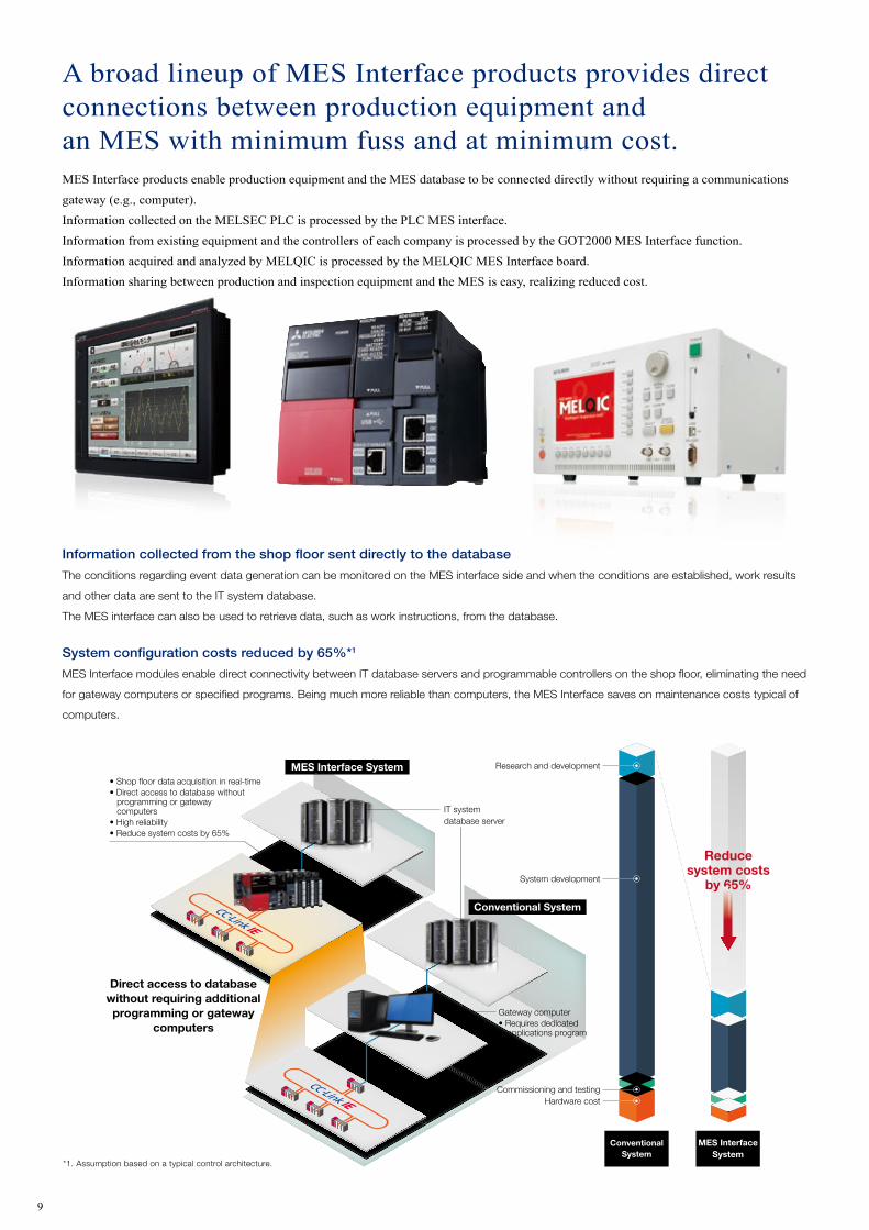
Information collected from the shop floor sent directly to the database
The conditions regarding event data generation can be monitored on the MES interface side and when the conditions are established, work results
and other data are sent to the IT system database.
The MES interface can also be used to retrieve data, such as work instructions, from the database.
System configuration costs reduced by 65%*1
MES Interface modules enable direct connectivity between IT database servers and programmable controllers on the shop floor, eliminating the need
for gateway computers or specified programs. Being much more reliable than computers, the MES Interface saves on maintenance costs typical of
computers.
Program-free easy configuration (Easy to Use)
With the special-purpose configuration tool, it is
possible to configure only the necessary items in the
correct order utilizing a simple wizard-style setup
process. SQL text is automatically generated based
on configurations, therefore eliminating the need to
create a program for data communication.
Ethernet
IT system
Direct access to IT system
MES Interface
Supporting functions that ensure data reliability
� Information with timestamps is temporarily
saved to a SD or CF card during
communication faults or when no response is
received from the server.
The data is automatically resent when the
problem is resolved, therefore securing data
continuity.
� SNTP enables time synchronization between
the information system and production
equipment.
� Log acquisition is possible during
communication faults.
A broad lineup of MES Interface products provides directconnections between production equipment andan MES with minimum fuss and at minimum cost.MES Interface products enable production equipment and the MES database to be connected directly without requiring a communications gateway (e.g., computer).Information collected on the MELSEC PLC is processed by the PLC MES interface.Information from existing equipment and the controllers of each company is processed by the GOT2000 MES Interface function.Information acquired and analyzed by MELQIC is processed by the MELQIC MES Interface board.Information sharing between production and inspection equipment and the MES is easy, realizing reduced cost.
The incorporation of MES Template Package allows assessment and examination of investment effect and performance using a test line, for easy application to the entire plant upon verification of effectiveness.MES Template Package offers templates of all general functions of the MES system to provide easy production management,
traceability, and preparation of Gantt charts.
It will also facilitate the future transition of data to a large-scale database system.
Extracts data from the sample database and displays Excel ® macros traceability information and Gantt chartsExcel ® macros
Database tables and sample data for production management, traceability, and Gantt chartsSample database
Delivers production management data to the PLC and sends collected performance data to the sample database
MES Interface project
DB
* The MES template package can be downloaded from the Mitsubishi Electric FA website: www.MitsubishiElectric.co.jp/fa
9

The various functions of FA-IT information interface products strongly support the informatization of production equipment.
*1. Assumption based on a typical control architecture.
Research and development
IT systemdatabase server
Gateway computer• Requires dedicated
applications program
MES Interface System
MES InterfaceSystem
ConventionalSystem
Conventional System
• Shop floor data acquisition in real-time• Direct access to database without
programming or gateway computers
• High reliability• Reduce system costs by 65%
System development
Commissioning and testingHardware cost
Reducesystem costs
by 65%
Direct access to databasewithout requiring additionalprogramming or gateway
computers
Information collected from the shop floor sent directly to the database
The conditions regarding event data generation can be monitored on the MES interface side and when the conditions are established, work results
and other data are sent to the IT system database.
The MES interface can also be used to retrieve data, such as work instructions, from the database.
System configuration costs reduced by 65%*1
MES Interface modules enable direct connectivity between IT database servers and programmable controllers on the shop floor, eliminating the need
for gateway computers or specified programs. Being much more reliable than computers, the MES Interface saves on maintenance costs typical of
computers.
Program-free easy configuration (Easy to Use)
With the special-purpose configuration tool, it is
possible to configure only the necessary items in the
correct order utilizing a simple wizard-style setup
process. SQL text is automatically generated based
on configurations, therefore eliminating the need to
create a program for data communication.
Ethernet
IT system
Direct access to IT system
MES Interface
Supporting functions that ensure data reliability
� Information with timestamps is temporarily
saved to a SD or CF card during
communication faults or when no response is
received from the server.
The data is automatically resent when the
problem is resolved, therefore securing data
continuity.
� SNTP enables time synchronization between
the information system and production
equipment.
� Log acquisition is possible during
communication faults.
A broad lineup of MES Interface products provides directconnections between production equipment andan MES with minimum fuss and at minimum cost.MES Interface products enable production equipment and the MES database to be connected directly without requiring a communications gateway (e.g., computer).Information collected on the MELSEC PLC is processed by the PLC MES interface.Information from existing equipment and the controllers of each company is processed by the GOT2000 MES Interface function.Information acquired and analyzed by MELQIC is processed by the MELQIC MES Interface board.Information sharing between production and inspection equipment and the MES is easy, realizing reduced cost.
The incorporation of MES Template Package allows assessment and examination of investment effect and performance using a test line, for easy application to the entire plant upon verification of effectiveness.MES Template Package offers templates of all general functions of the MES system to provide easy production management,
traceability, and preparation of Gantt charts.
It will also facilitate the future transition of data to a large-scale database system.
Extracts data from the sample database and displays Excel ® macros traceability information and Gantt chartsExcel ® macros
Database tables and sample data for production management, traceability, and Gantt chartsSample database
Delivers production management data to the PLC and sends collected performance data to the sample database
MES Interface project
DB
* The MES template package can be downloaded from the Mitsubishi Electric FA website: www.MitsubishiElectric.co.jp/fa
Job configuration wizard screen
Mapping configuration screen
Automatically generated SQL text
10

� Informatization of inspection data using highly reliable hardwareBy being HDD-free and equipped with a real-time OS, long-term stable use as an FA device is possible, and various communications such as MES Interface, CC-Link, CAN and GP-IB are supported
� The adoption of VISIO allows high functionality with easy programmingMulti-channel sampling maximum 10MHz/data analysis FFT, digital filter, peak detection, rise/fall detection, etc.High-speed logging (maximum 1ms interval, maximum 90 channels)/built-in computer card slot (maximum 16GB)
Data collection analyzer MELQIC MES Interface function
Collecting production and inspection information from the shop floor in real-time.
Jig control
PLCControl panel
Conductivity inspection location
Products
Conveyor control
Multiple meters
Multiple meters
Voltage generator
MELQIC
GOT2000 HMI MES Interface function
The GOT2000 HMI collects and sends data from connected FA products to the MES.
MELSEC iQ-R/MELSEC-Q PLC MES Interface
PLCs are connected directly to the MES without the use of gateway PCs or communication programs.
Ethernet
CC-Link IE
SSCNET#/HCC-Link IEB/NET
• Production plan management
• Parts inventory management
• Product inventory management
SQL
MES database server
MESDatabase server • Production plan management
• Parts inventory management• Product inventory management
Ethernet
SQL
� Enhances traceability and supports visualization of the entire factory.
� When machining is complete or an alarm occurs, the information collected by the CNC is sent from the built-in MES interface to the database.
� Achieves visualization of operation status, which simplifies the creation of production plans and production management, as well as the visualization of machining results and alarm occurrence status so that a higher standard of quality control can be realized.
CNC sends machining information and operation status of machine tools to MES.
M800/M80 Series computerized numerical controller MES interface function
Workpiece being machined
Workpiece ID
Machine toolMachined product
Production management system
Ethernet
SQL
Machining information
At machining completionWorkpiece ID, machining start/finish time, maximum spindle load, power consumption, tool ID number, tool offset, etc.
At alarm occurrenceWorkpiece ID, alarm occurrence time, alarm description, number of tool used, tool offset, etc.
� Comprehensive plant information, including production, equipment, quality, and energy data, are collected and managed via a seamless network.
� Even the most detailed equipment-level information can be collected via an extensive field network.
� Machine tools and equipment that utilize third-party PLCs can be easily configured into the open network.
POS terminal
EthernetSQL
MES database server • Production plan management
• Parts inventory management
• Product inventory management
Work-receivingstage
3rd party PLCs
Shippingstage
Sub assembly line Main assembly line
Workprocess 4
Workprocess 1
Workprocess 2
Temperatureregulator
Workprocess 3
Processing line
� Collects data from existing equipment and other equipment that utilize third-party PLCs.
� Supports operators’ tasks by providing access to a barcode reader, document viewer, or other such tools.
� Equipped with substantial information management functions characteristic of a display unit (HMI).• Displays logging data (logging function + display of historical trend graph/historical trend list)• Management of alarm history, such as equipment alarms and production history• Management of worker operational history
11

� Informatization of inspection data using highly reliable hardwareBy being HDD-free and equipped with a real-time OS, long-term stable use as an FA device is possible, and various communications such as MES Interface, CC-Link, CAN and GP-IB are supported
� The adoption of VISIO allows high functionality with easy programmingMulti-channel sampling maximum 10MHz/data analysis FFT, digital filter, peak detection, rise/fall detection, etc.High-speed logging (maximum 1ms interval, maximum 90 channels)/built-in computer card slot (maximum 16GB)
Data collection analyzer MELQIC MES Interface function
Collecting production and inspection information from the shop floor in real-time.
Jig control
PLCControl panel
Conductivity inspection location
Products
Conveyor control
Multiple meters
Multiple meters
Voltage generator
MELQIC
GOT2000 HMI MES Interface function
The GOT2000 HMI collects and sends data from connected FA products to the MES.
MELSEC iQ-R/MELSEC-Q PLC MES Interface
PLCs are connected directly to the MES without the use of gateway PCs or communication programs.
Ethernet
CC-Link IE
SSCNET#/HCC-Link IEB/NET
• Production plan management
• Parts inventory management
• Product inventory management
SQL
MES database server
MESDatabase server • Production plan management
• Parts inventory management• Product inventory management
Ethernet
SQL
� Enhances traceability and supports visualization of the entire factory.
� When machining is complete or an alarm occurs, the information collected by the CNC is sent from the built-in MES interface to the database.
� Achieves visualization of operation status, which simplifies the creation of production plans and production management, as well as the visualization of machining results and alarm occurrence status so that a higher standard of quality control can be realized.
CNC sends machining information and operation status of machine tools to MES.
M800/M80 Series computerized numerical controller MES interface function
Workpiece being machined
Workpiece ID
Machine toolMachined product
Production management system
Ethernet
SQL
Machining information
At machining completionWorkpiece ID, machining start/finish time, maximum spindle load, power consumption, tool ID number, tool offset, etc.
At alarm occurrenceWorkpiece ID, alarm occurrence time, alarm description, number of tool used, tool offset, etc.
� Comprehensive plant information, including production, equipment, quality, and energy data, are collected and managed via a seamless network.
� Even the most detailed equipment-level information can be collected via an extensive field network.
� Machine tools and equipment that utilize third-party PLCs can be easily configured into the open network.
POS terminal
EthernetSQL
MES database server • Production plan management
• Parts inventory management
• Product inventory management
Work-receivingstage
3rd party PLCs
Shippingstage
Sub assembly line Main assembly line
Workprocess 4
Workprocess 1
Workprocess 2
Temperatureregulator
Workprocess 3
Processing line
� Collects data from existing equipment and other equipment that utilize third-party PLCs.
� Supports operators’ tasks by providing access to a barcode reader, document viewer, or other such tools.
� Equipped with substantial information management functions characteristic of a display unit (HMI).• Displays logging data (logging function + display of historical trend graph/historical trend list)• Management of alarm history, such as equipment alarms and production history• Management of worker operational history
12

Can be attached to DIN rail! Stand-alone type that can be easily added on PLC
Ethernet
Connection to PLC via Ethernet or serial (RS-232) connection
Various measurement data are directly collected by the data logger to provide high-speed, easy, and low-cost data logging solutions with greater precision than conventional modules.Because there is no need to install PCs or dedicated devices on the shop floor,using the data logger contributes to minimizing system costs and improving system reliability.
* Forwarding to a Windows shared folder is only possible when using the MELSEC iQ-R High-speed Data Logger
MELSEC iQ-R/MELSEC-Q High-speed Data Logger
PLC data logging possible with simple configuration.
� An Assistant Wizard helps set up the appropriate logging method for the intended use, and the Viewer Utility generates trend graphs to facilitate data monitoring and analyses.
� Since no PC or protocol converter is needed to collect data, initial costs can be kept extremely low.
� Realize logging data management on the upper server by forwarding to an FTP server/Windows shared folder.
Layout file sent using High-speed Data Logger configuration tool
High-speed Data Logger
Computer
Layout file(Excel file format)
Data is recorded in synchronization with sequence scanning! (High-speed Data Logger)
Normal range
0 �Time (ms)100 200 300
Data samplingby the High-speed Data Logger(High-speed sampling interval: 1ms at the fastest)
The control value hasexceeded its limit. Let’sadjust the equipment!
Causes of errors that might be missed by conventional data logging systems
Control valueControl value (PC)
[ High-speed Data Logger / BOX Data Logger: Shared functions ]
� High-speed, high-accuracy data logging
� Assistance in the form of a wizard makes it easy to set the appropriate logging method for the purpose. In addition, display of trend graphs
by the display utility provides a simple expression of monitoring data analysis results
� Because no computer or protocol converter is necessary for data collection, initial costs are significantly reduced
� The use of CF cards enables data logging over an extended period. In addition, sending saved log files to the server makes it possible
to log data in excess of the capacity of the CF cards
� Setting Excel file templates for layout, graphs, formulas, etc. in advance makes it possible to save data as ledgers or reports
� GX Log Viewer is used as the display and analysis tool, enabling display and analysis of high volumes of collected data
using easy-to-understand operations
� Device data essential for detailed checks, etc. can be read from a recipe file (CSV format) and written to the PLC CPU at the specified timing
• Utilization of partner software products
MELSEC iQ-R/MELSEC-Q PLC C controller
Control, information processing and upper-level communication processing
are possible with partner software products and a C/C++ language program.
Automatic creation of graphical materials to suit the application, such as daily reports, ledgers and reports!
The High-speed Data Sampling Function synchronizes the data logging task with sequence scanning, which is the smallest time unit of control, to ensure high-speed, high-precision data logging.The sampled data can be used not only to analyze machine performance, but also to identify the cause of errors when they occur, because the data logger records even the smallest change in control values.
CIMOPERATOR® (Nippon Denno Co., Ltd.)
Connect to existing equipment system while its running and begin collecting equipment data immediately (Box Data Logger)
Module can be attached to the DIN rail and easily connected to equipment via Ethernet or RS-232 serial port afterwards. Data logging for PLCs of other companies is also possible.
Host computer(MES) Equipment
C controller
Equipment PLC
Host computer
Analysis server
EquipmentC controller
Equipment PLC
Simply by configuring a data device-trigger relay handshake, various communication functions can be added to the PLC.Various communication logs and PLC logs can also be output.A large volume of equipment processing data can be reported without the use of a gateway computer and existing equipment can be brought online.
Various communications possible program-free
• Program development using C/C++ language� Preinstall real-time OS (VxWorks)
� Software development can be performed in an integrated development environment (CW Workbench)
� Prepare a special-purpose tool to perform configuration/diagnosis on the various units
CIMSNIPER (Nippon Denno Co., Ltd.)
CIMSNIPER enables direct collection of target data and possesses features and functions enabling upper-level data analysis to be performed with minimal man-hours.
Realize low-cost data mining
A product offering the information you want, when you want it, and in the format you want it in. Through configuration only, the monitoring of equipment information and host-to-host communication*, as well as automatic collection of data, are possible.* Host-to-host communication-supporting protocols: SECS-I, HSMS, GEM, FTP• Please consult with us regarding special protocols.
Program-free collection possible
Various types of analysis tools required for data mining are supported.* Analysis tools must be prepared separately.
Various analysis tools supported
13

Can be attached to DIN rail! Stand-alone type that can be easily added on PLC
Ethernet
Connection to PLC via Ethernet or serial (RS-232) connection
Various measurement data are directly collected by the data logger to provide high-speed, easy, and low-cost data logging solutions with greater precision than conventional modules.Because there is no need to install PCs or dedicated devices on the shop floor,using the data logger contributes to minimizing system costs and improving system reliability.
* Forwarding to a Windows shared folder is only possible when using the MELSEC iQ-R High-speed Data Logger
MELSEC iQ-R/MELSEC-Q High-speed Data Logger
PLC data logging possible with simple configuration.
� An Assistant Wizard helps set up the appropriate logging method for the intended use, and the Viewer Utility generates trend graphs to facilitate data monitoring and analyses.
� Since no PC or protocol converter is needed to collect data, initial costs can be kept extremely low.
� Realize logging data management on the upper server by forwarding to an FTP server/Windows shared folder.
Layout file sent using High-speed Data Logger configuration tool
High-speed Data Logger
Computer
Layout file(Excel file format)
Data is recorded in synchronization with sequence scanning! (High-speed Data Logger)
Normal range
0 �Time (ms)100 200 300
Data samplingby the High-speed Data Logger(High-speed sampling interval: 1ms at the fastest)
The control value hasexceeded its limit. Let’sadjust the equipment!
Causes of errors that might be missed by conventional data logging systems
Control valueControl value (PC)
[ High-speed Data Logger / BOX Data Logger: Shared functions ]
� High-speed, high-accuracy data logging
� Assistance in the form of a wizard makes it easy to set the appropriate logging method for the purpose. In addition, display of trend graphs
by the display utility provides a simple expression of monitoring data analysis results
� Because no computer or protocol converter is necessary for data collection, initial costs are significantly reduced
� The use of CF cards enables data logging over an extended period. In addition, sending saved log files to the server makes it possible
to log data in excess of the capacity of the CF cards
� Setting Excel file templates for layout, graphs, formulas, etc. in advance makes it possible to save data as ledgers or reports
� GX Log Viewer is used as the display and analysis tool, enabling display and analysis of high volumes of collected data
using easy-to-understand operations
� Device data essential for detailed checks, etc. can be read from a recipe file (CSV format) and written to the PLC CPU at the specified timing
• Utilization of partner software products
MELSEC iQ-R/MELSEC-Q PLC C controller
Control, information processing and upper-level communication processing
are possible with partner software products and a C/C++ language program.
Automatic creation of graphical materials to suit the application, such as daily reports, ledgers and reports!
The High-speed Data Sampling Function synchronizes the data logging task with sequence scanning, which is the smallest time unit of control, to ensure high-speed, high-precision data logging.The sampled data can be used not only to analyze machine performance, but also to identify the cause of errors when they occur, because the data logger records even the smallest change in control values.
CIMOPERATOR® (Nippon Denno Co., Ltd.)
Connect to existing equipment system while its running and begin collecting equipment data immediately (Box Data Logger)
Module can be attached to the DIN rail and easily connected to equipment via Ethernet or RS-232 serial port afterwards. Data logging for PLCs of other companies is also possible.
Host computer(MES) Equipment
C controller
Equipment PLC
Host computer
Analysis server
EquipmentC controller
Equipment PLC
Simply by configuring a data device-trigger relay handshake, various communication functions can be added to the PLC.Various communication logs and PLC logs can also be output.A large volume of equipment processing data can be reported without the use of a gateway computer and existing equipment can be brought online.
Various communications possible program-free
• Program development using C/C++ language� Preinstall real-time OS (VxWorks)
� Software development can be performed in an integrated development environment (CW Workbench)
� Prepare a special-purpose tool to perform configuration/diagnosis on the various units
CIMSNIPER (Nippon Denno Co., Ltd.)
CIMSNIPER enables direct collection of target data and possesses features and functions enabling upper-level data analysis to be performed with minimal man-hours.
Realize low-cost data mining
A product offering the information you want, when you want it, and in the format you want it in. Through configuration only, the monitoring of equipment information and host-to-host communication*, as well as automatic collection of data, are possible.* Host-to-host communication-supporting protocols: SECS-I, HSMS, GEM, FTP• Please consult with us regarding special protocols.
Program-free collection possible
Various types of analysis tools required for data mining are supported.* Analysis tools must be prepared separately.
Various analysis tools supported
Series Model Features
iQ-R Series
R12CCPU-VStandard model
High-speed control utilizing newly developed high-speed system bus realizes significantly shorter tact time
RD55UP06-VC intelligent function module NEW
Ability to link each CPU enables operation as an intelligent function module, making C and C++ program processing possibleOriginal intelligent function module can be developed for communication/data processing and information processing
Q Series
Q12DCCPU-VStandard model
Installation of RTOS (VxWorks) enables high-speed I/O controlOptimized by replacing microcomputer-control system
Q24DHCCPU-VHigh-end model
Installation of high-speed CPU and RTOS (VxWorks) enables optimization by replacing personal computer-based control system
Q24DHCCPU-VGModel with display function
VGA port added to high-end model and middleware installed to support GUI output
Q24DHCCPU-LSModel supporting general-purpose OS
Supports general-purpose OS such as Linux and T-KernelMakes effective use of software assets
14

◾ MES Interface FunctionsFunctions Description
DB record input/output function Function to perform the reading/writing of database data for upper-level information system.
Device memory input/output function Function to perform the reading/writing of device memory data for CPU module.
Trigger condition monitoring function Function to monitor values such as time and device tag elements, and start a job when trigger conditions change from false to true (condition establishment).
Data calculation/processing function Function to perform addition, subtraction, multiplication and division, remainder and character string operations.
Program execution function Function to execute programs on the server from MES Interface.
Database bufferingFunction for buffering transmission data to the database and resending after a normal state is recovered in the case of data interface trouble, such as lost network between MES Interface and database or when the database has crashed.
◾ MES Interface SpecificationsFunctions RD81MES96 QJ71MES96
Peripheral device connection port
Ethernet 2CH(1000BASE-T/100BASE-TX/10BASE-T) 1CH(100BASE-TX/10BASE-T)
Database interface Database type*1 Oracle database, Microsoft SQL Server, Microsoft Access Oracle database, Microsoft SQL Server, Microsoft Access, etc.
Job
Configurable number Max. 64 points/project
Trigger buffering count 192 128
Trigger condition (combinable number) 2 conditions/job
Action
Configurable numberMax. 1,920 actions/project
Max. 30 actions/job(20 main processing actions + 10 pre/post-processing actions)
Max. 640 actions/projectMax. 10 actions/job
Type SELECT, INSERT, UPDATE, DELETE, Multi-SELECT, STORED PROCEDURE
Number of DB communication action fields Max. 65,536 fields/project Max. 8,192 fields/project
Number of calculations possible Max. 20/calculation action
Program execution Configurable numberMax. 10/job
(maximum of 10 including pre/post-processing)Max. 2/job
(1 each before executing the first action and after executing the last action)
Device tag
Access destination deviceiQ-R Series (own station, other stations), Q Series (other stations), L
Series (other stations)iQ-R Series (other stations), Q Series (own station, other stations), L
Series (other stations), A Series (other stations)
Access interval Shortest sequence scan (up to 8K points) Shortest 100ms (up to 96 points)
Number of tags 64 tags/project
Number of elements1,024 points/tag
65,536 points/project256 points/tag
4,096 points/project
DB buffer Buffer size during communication fault*1 2,048MB 512MB
*1.Refertothemanualfordetails.
MELSEC iQ-R series MES Interface module
Product name Model Description
MES Interface module NEW RD81MES96 MES Interface Function execution module
SD memory card
NZ1MEM-2GBSD 2GB
NZ1MEM-4GBSD 4GB
NZ1MEM-8GBSD 8GB
NZ1MEM-16GBSD 16GB
MELSEC iQ-R series MES Interface Support Tool
Product name Model Description
MES Interface Support Tool NEW(MX MESInterface-R)
SW1DND-RMESIF-JMELSEC iQ-R seriesMES Interface Function Configuration Tool, etc.
MELSEC-Q series MES Interface module
Product name Model Description
MES Interface module QJ71MES96 MES Interface Function execution module
CompactFlash card
GT05-MEM-128MC 128MB
GT05-MEM-256MC 256MB
QD81MEM-512MBC 512MB
QD81MEM-1GBC 1GB
MELSEC-Q series MES Interface Support Tool
Product name Model Description
MES Interface Support Tool(MX MESInterface)
SW1DND-MESIF-JMELSEC-Q seriesMES Interface Function Configuration Tool, etc.
MES Interface M800/M80 Series CNC
Product name Model Description
MITSUBISHI CNC M800/M80
FCA850U/FCA830U/
FCA850H-••/FCA830H-••/FCA80H-••/FCA80P-••
M800/M80 Series control unit
GOT2000 MES Interface functions
Product name Model Description
GOT2000GT27••-••••GT25••-••••
GOT2000 series module
MES Interface function license GT25-MESIFKEY-• MES Interface function license
SD memory card
NZ1MEM-2GBSDNZ1MEM-4GBSDNZ1MEM-8GBSDNZ1MEM-16GBSD
Supports SD memory card
GOT2000 MES Interface configuration tool
Product name Model Description
Screen creation softwareGT Works3
SW1DND-GTWK3-JSets MES Interface actions, Tool for configuring DB connection service, etc.
MELQIC MES Interface functions
Product name Model Description
Data collection analyzer
IU2-4M10HA(-E)IU2-5M10(-E)IU2-5M10LIU2-3M10
IU2-3M10L
IU2 series MELQIC module
MES Interface board IU2-1EMES MES Interface function executing board
CompactFlash card − Required. 128 Mbytes or more
MELQIC MES Interface Support Tool
Product name Model Description
MES Interface Support Tool(IU MES Interface)
SW1DNC-IUMIF MES Interface Function Configuration Tool, etc.
15

◾ High-speed Data Logger / BOX Data Logger: FunctionsItem Description
High-speed data collection function Function for collecting by synchronizing with PLC scanning (only for High-speed Data Logger)
Logging function Function for collection and recording of data and event data.
Data logging function Function for recording data continuously or when triggered.
Event logging function Function for recording sequence of occurrence of recorded events as a time history.
FTP server function Function for reading and deletion of saved High-speed Data Logger module files from PC FTP client software.
File forwarding functionFunction for forwarding saved files to the computer FTP server or Windows shared folder (Windows shared folder only possible when used with MELSEC iQ-R High-speed Data Logger)
e-mail sending function Function for sending notification of events and saved files in e-mail.
Excel file saving function Function for saving of collected data in Excel file format. (Report function)
CSV file saving function Function for saving of collected data in CSV file format.
Time synchronization function Function for synchronization of time data with data collection times. Function for synchronization with SNTP server in the network or PLC CPU (internal clock in the case of GOT and MELQIC).
◾ High-speed Data Logger / BOX Data Logger: SpecificationsItem MELSEC iQ-R High-speed Data Logger MELSEC-Q High-speed Data Logger BOX Data Logger
Device type Base unit-mounted type Standalone type
Data collection
Data collection interval
High-speed data collection
Synchronized with sequence scanning time 0.5 - 0.9ms, 1 - 32,767ms (during trigger logging)
2 - 32,767ms (during continuous logging)
Synchronized with sequence scanning time 1-32,767 milliseconds (Triggered logging)
3-32,767 milliseconds (During continuous logging) −
General-purpose data collection
0.1-0.9 seconds, 1-32,767 seconds, time interval specification (Hour, minute and second specification)
Number of data collected
High-speed data collection
Total number of data: Maximum 32,768 (Per setting: 1024)Total number of devices: Maximum 32,768 (Per setting 4096)
Total number of data: Maximum 8,192 (Per setting: 256)Total number of devices: Maximum 8,192 (Per setting 256) −
General-purpose data collection
Total number of data: Maximum 65,536 (Per setting: 1,024); Total number of devices: Maximum of 262,144 (Per setting: 4,096)
Total number of data: Maximum 16,384 (Per setting: 256); Total number of devices: Maximum of 262,144 (Per setting: 4,096)
Format for data output (CSV files)
Format for bits and decimals: Number of decimal places 0-14; Format for exponents: Number of decimal places 0-14,
hexadecimal format, character strings, numerical stringsThe following designations can be made for trigger
logging (output only one line after trigger)・Time/cumulative time Decimal format: 0 - 4 decimals after the decimal point・Count/cumulative count Decimal format: 0 decimals after the decimal point
Format for bits and decimals: Number of decimal places 0-14; Format for exponents: Number of decimal places 0-14, hexadecimal format, character strings, numerical strings
Scaling Four arithmetic operations: Computations combining (×,÷) and (+,-)
Targets for data collection MELSEC iQ-R/Q/L Series PLCs MELSEC-Q/L Series PLCsMELSEC-Q/L/A/F Series PLC,
Omron/Siemens/Rockwell PLCs
Data logging
Number of settings Maximum of 64
Logging types Continuous logging, triggered logging
File formatCSV file (File extension: CSV),
・Unicode text file (extension: TXT)Binary file (File extension: BIN)
CSV file (File extension: CSV), Binary file (File extension: BIN)
Event logging
Number of settings Maximum of 64
Number of events Maximum of 256 for each event logging setting Maximum of 64 for each event logging setting
File formatCSV file (File extension: CSV);
・Unicode text file (extension: TXT)Binary file (File extension: BIN)
CSV file (File extension: CSV); Binary file (File extension: BIN)
Event conditionsData conditions: Bit ON/OFF, data ⇔ Comparison of constants, data ⇔ Data comparison, data modification; Frequency of establishment of
conditions: Three conditions; Sequence for establishment of conditions (Sequence and time conditions): Up to four conditions
Report
Number of settings Maximum of 64
File format Excel format (File extension :XLS)
Output data type Data in data logging files, time of generation, current value data
Number of output data 64 layouts, total of 65,535 cells for each report setting
e-mail sending function
Use Notification of occurrence of event, sending of saved files
Attached files Mail for sending of saved files, without event notification mail: Saved files (CSV, Binary, Excel) to a maximum of 512 KB
Delivery addresses Maximum of 16 groups
Mail client operation confirmation software Microsoft Outlook 2013 Mixrosoft Outlook Express 6.0, Microsoft Windows Mail 6.0
FTP server Use Reading and deletion of saved files, writing, reading and deletion of recipe files
FTP client operation confirmation software Microsoft Internet Explorer 8.0/9.0/10.0/11.0 Windows Internet Explorer 7.0/8.0/9.0/10.0
Number of sessions 10
FTP clientUse Transfer of stored files
FTP server operation confirmation software Microsoft Internet Information Service
Windowsshared folder
Operation confirmation operation system
Microsoft Windows 7
StarterHome Premium
ProfessionalUltimate
Enterprise −
Microsoft Windows 8Microsoft Windows 8.1
(Unbranded)Pro
Enterprise
Recipe
Number of data Maximum 256 data
Number of records Maximum 256 records
Recipe files CSV files (File extension: CSV); Maximum of 256 files
Modes of execution Dedicated instructions (Rudder program), setting tool
Compatible memory cards SD cards (Maximum of 16GB) CF cards (Maximum of 8GB)
External dimensions 27.8(W)x106(H)x110(D)mm 98(H)×27.4(W)×90(D)mm 98(H)×110.8(W)×145.5(D)mm
MELSEC iQ-R series High-speed Data Logger module
Product name Model name DescriptionHigh-speed Data Logger module NEW
RD81DL96High-speed Data Logger module *Requires an SD card
SD card
NZ1MEM-2GBSD 2GB
NZ1MEM-4GBSD 4GB
NZ1MEM-8GBSD 8GB
NZ1MEM-16GBSD 16GB
MELSEC iQ-R series High-speed Data Logger module Configuration Tool
Product name Model name DescriptionTool for MELSEC iQ-RHigh-speed Data Logger Tool for module NEW
SW1DNN-RDLUTL-J
High-speed Data Logger module logging setting tool
MELSEC-Q series High-speed Data Logger module
Product name Model name DescriptionHigh-speed Data Logger module QD81DL96 High-speed Data Logger module *Requires compact flash card.
Compact flash card
QD81MEM-512MBC 512MB
QD81MEM-1GBC 1GB
QD81MEM-2GBC 2GB
QD81MEM-4GBC 4GB
QD81MEM-8GBC 8GB
MELSEC-Q series High-speed Data Logger module Configuration Tool
Product name Model name DescriptionHigh-speed Data Logger module Tool for module
SW1DNN-DLUTL-JMELSEC-Q High-speed Data Logger module logging setting tool
BOX Data Logger
Product name Model name DescriptionBOX Data Logger NZ2DL BOX Data Logger *Requires compact flash card.
Compact flash card
QD81MEM-512MBC 512MB
QD81MEM-1GBC 1GB
QD81MEM-2GBC 2GB
QD81MEM-4GBC 4GB
QD81MEM-8GBC 8GB
BOX Data Logger Configuration Tool
Product name Model name DescriptionBOX Data Logger setting tool SW1DNN-NLUTL-J BOX Data Logger logging setting tool
BOX Data Logger Setting Tool
Product name Model name DescriptionGX LogViewer SW1DNN-VIEWER-J Collected data display and analysis tool
16

This system provides a means of efficiently managing production process status(production quantity, cycle time) and checking the error history of different aspects of the line. Device data is easily collected from various controllers via the controller network and communicated directly to a database server via MES Interface.
Manages operational performance data(production volume, cycle time, etc.).
[ Installation effects ]
■ Efficiently manage production performances.
■ Effectively realize quick recovery and intelligent preventative maintenance measures by proper management of real time errors and historical data.
Applying e-F@ctory to various different types of applications,su ited for the users best needs.
(Example: Printer cartridge manufacturing line)
Production management systemApplication example
TimeLine numberError codeTime occurredRecovery timeCompletion time・・・・・・・・・
TimeLine numberProduction quantityCycle time・・・・・・・・・
Database server
Ethernet
Dozens of modules
Equipment A Equipment B Equipment C
Production line main controllerGOT2000
Master PLC (with MES Interface)
MELSECNET
Ensuring accumulative collection of production process data such as process number, operation history, and quality directly from the shop floor.
By having an alarm management system incorporated into the production line,various detailed information such as process, error description, cause, etc., can be efficiently collected and managed.This system read a recipe information such as operator, error description, etc. when it starts up and detailed information in the event of an error can be input and sent from HMI.
[ Installation effects ]■ Automated alarm management provides accurate and fast analysis of errors.
■ Equipment maintenance procedures are improved substantially by managing detailed information within the server.
TimeProcess numberError typeOperatorError detailsError code·········
Operators listError detailsError codes, etc.·········
Ethernet
Database server
SQL
Receive whensystem starts up Receive in
the event of an error
Error! GOT2000 (with MESInterface)
(Example: Automotive engine machining line)
Collects error information and in case of an error, information can be input/sent from HMI.
Alarm information management systemApplication example
Inspection process
TimeSerial numberEquipment numberTool conditionProcessing environmentInspection result·········
Database server
Sent after process completionEthernet
SQL
ID tag Robot Processing machine
Master PLC(with MES Interface module)
Process A
SQL
Process B
Sent after completion of inspection
SQLProduction performance
Lot no.Measured values
Pass/fail judgmentRecorded data
etc.
Traceability systemApplication example
Critical data such as equipment number, operation history, and quality data are collected from each individual process or machining point and fed directly to the database server. The serial number of each machining process (engine), processing history, and inspection history are sent to the database after completion.
[ Installation effects ]
■ Traceability data can be used torespond promptly to productiondown situations and quality faults.
■ Trends in operation status and quality information are closely monitored, highlighting production quality variances effectively in real time.
[ Installation effects ]■ Shortens the time needed to change products.■ Prevents human errors when setting parameters for product changes.
The ingredient ratio data for each product is managed as a recipe file by a personal computer.Using the FTP server function, the recipe files are stored on the SD card of the High-speed Data Logger Module.When changing products on the production line, a dedicated command retrieves the relevant recipe file needed for production.
Allows management of ingredient ratio data by PC, to ensure smooth changes in ingredient ratios per product.
Ingredient ratio management systemApplication example
Create a recipe file.Recipe files can be created easily by using the High-Speed Data Logger module setting tool.
Store the recipe file using FTP or other tool.
Store the recipe file in the SD card of the High-Speed Data Logger.
Writing the device valueThe device value is read from the recipe file in the SD card and sent to the PLC CPU.
Rewriting the recipe fileThe device value from the PLC CPU is written to the recipe file in the SD card.
PLC CPURecipe editing
screen
Recipefile
(CSV) High-speed Data Logger Module
Dedicated command
Rawmaterial A30%
Rawmaterial B30%
Rawmaterial C40%
Rawmaterial A40%
Rawmaterial B40%
Rawmaterial C20%
Rawmaterial A20%
Rawmaterial B50%
Rawmaterial C30%
Production of Product 01 Production of Product 02 Production of Product 03
Change in ingredientratio data
Change in ingredientratio data
The recipe file containing ingredient ratio is stored in the PC.
Recipe 01
30%
30%
40%
Recipe 02
40%
40%
20%
Recipe 02
40%
40%
20%
Recipe 03
20%
50%
30%
Raw material A
Raw material B
Raw material C
Raw material A
Raw material B
Raw material C
The relevant ingredient ratio data is retrieved by dedicated command
(retrieval of Recipe02 data)
The relevant ingredient ratio data is retrievedby dedicated command
(retrieval of Recipe03 data)
Error occurs!Time
Process
Error
Name
Details
Cause
10:20:31
Assembly A
Transportation error
Confirm
Error code selection ×
001 Malfunction
002 Overweight
003 Life
010 Faulty operation
■ Input screen is automatically displayed once an error occurs.■ Detailed error information is multiple-choice entry (achieve uniformity in the entry)■ Specific information are retrieved from the database and displayed on screen.
(Example: Food processing line)
17

This system provides a means of efficiently managing production process status(production quantity, cycle time) and checking the error history of different aspects of the line. Device data is easily collected from various controllers via the controller network and communicated directly to a database server via MES Interface.
Manages operational performance data(production volume, cycle time, etc.).
[ Installation effects ]
■ Efficiently manage production performances.
■ Effectively realize quick recovery and intelligent preventative maintenance measures by proper management of real time errors and historical data.
Applying e-F@ctory to various different types of applications,su ited for the users best needs.
(Example: Printer cartridge manufacturing line)
Production management systemApplication example
TimeLine numberError codeTime occurredRecovery timeCompletion time・・・・・・・・・
TimeLine numberProduction quantityCycle time・・・・・・・・・
Database server
Ethernet
Dozens of modules
Equipment A Equipment B Equipment C
Production line main controllerGOT2000
Master PLC (with MES Interface)
MELSECNET
Ensuring accumulative collection of production process data such as process number, operation history, and quality directly from the shop floor.
By having an alarm management system incorporated into the production line,various detailed information such as process, error description, cause, etc., can be efficiently collected and managed.This system read a recipe information such as operator, error description, etc. when it starts up and detailed information in the event of an error can be input and sent from HMI.
[ Installation effects ]■ Automated alarm management provides accurate and fast analysis of errors.
■ Equipment maintenance procedures are improved substantially by managing detailed information within the server.
TimeProcess numberError typeOperatorError detailsError code·········
Operators listError detailsError codes, etc.·········
Ethernet
Database server
SQL
Receive whensystem starts up Receive in
the event of an error
Error! GOT2000 (with MESInterface)
(Example: Automotive engine machining line)
Collects error information and in case of an error, information can be input/sent from HMI.
Alarm information management systemApplication example
Inspection process
TimeSerial numberEquipment numberTool conditionProcessing environmentInspection result·········
Database server
Sent after process completionEthernet
SQL
ID tag Robot Processing machine
Master PLC(with MES Interface module)
Process A
SQL
Process B
Sent after completion of inspection
SQLProduction performance
Lot no.Measured values
Pass/fail judgmentRecorded data
etc.
Traceability systemApplication example
Critical data such as equipment number, operation history, and quality data are collected from each individual process or machining point and fed directly to the database server. The serial number of each machining process (engine), processing history, and inspection history are sent to the database after completion.
[ Installation effects ]
■ Traceability data can be used torespond promptly to productiondown situations and quality faults.
■ Trends in operation status and quality information are closely monitored, highlighting production quality variances effectively in real time.
[ Installation effects ]■ Shortens the time needed to change products.■ Prevents human errors when setting parameters for product changes.
The ingredient ratio data for each product is managed as a recipe file by a personal computer.Using the FTP server function, the recipe files are stored on the SD card of the High-speed Data Logger Module.When changing products on the production line, a dedicated command retrieves the relevant recipe file needed for production.
Allows management of ingredient ratio data by PC, to ensure smooth changes in ingredient ratios per product.
Ingredient ratio management systemApplication example
Create a recipe file.Recipe files can be created easily by using the High-Speed Data Logger module setting tool.
Store the recipe file using FTP or other tool.
Store the recipe file in the SD card of the High-Speed Data Logger.
Writing the device valueThe device value is read from the recipe file in the SD card and sent to the PLC CPU.
Rewriting the recipe fileThe device value from the PLC CPU is written to the recipe file in the SD card.
PLC CPURecipe editing
screen
Recipefile
(CSV) High-speed Data Logger Module
Dedicated command
Rawmaterial A30%
Rawmaterial B30%
Rawmaterial C40%
Rawmaterial A40%
Rawmaterial B40%
Rawmaterial C20%
Rawmaterial A20%
Rawmaterial B50%
Rawmaterial C30%
Production of Product 01 Production of Product 02 Production of Product 03
Change in ingredientratio data
Change in ingredientratio data
The recipe file containing ingredient ratio is stored in the PC.
Recipe 01
30%
30%
40%
Recipe 02
40%
40%
20%
Recipe 02
40%
40%
20%
Recipe 03
20%
50%
30%
Raw material A
Raw material B
Raw material C
Raw material A
Raw material B
Raw material C
The relevant ingredient ratio data is retrieved by dedicated command
(retrieval of Recipe02 data)
The relevant ingredient ratio data is retrievedby dedicated command
(retrieval of Recipe03 data)
Error occurs!Time
Process
Error
Name
Details
Cause
10:20:31
Assembly A
Transportation error
Confirm
Error code selection ×
001 Malfunction
002 Overweight
003 Life
010 Faulty operation
■ Input screen is automatically displayed once an error occurs.■ Detailed error information is multiple-choice entry (achieve uniformity in the entry)■ Specific information are retrieved from the database and displayed on screen.
(Example: Food processing line)
18

IntegratedEngineering
IntegratedNetwork
AutomationController
MES
ERP
Further reduce TCO while securing your manufacturing assets Automation ControllerImprove productivity and product quality
1. High-speed system bus realizing improved system performance
2. On-screen multi-touch control enabling smooth GOT (HMI) operations
Integrated NetworkBest-in-class integrated network optimizing production capabilities
1. CC-Link IE supporting 1 Gbps high-speed communication
2. Seamless connectivity within all levels of manufacturing with SLMP
Centralized EngineeringIntegrated engineering environment with system level features
1. Automatic generation of system configuration
2. Share parameters across multiple engineering software via MELSOFT Navigator
3. Changes to system labels are reflected between PAC and HMI
iQ Platform for maximum return on investmentMinimize TCO, Seamless integration, Maximize productivity, Transparent communications: these are common items that highlight the benefits of the iQ Platform and e-F@ctory. The iQ Platform minimizes TCO at all phases of the automation life cycle by improving development times, enhancing productivity, reducing maintenance costs, and making information more easily accessible across the plant. Together with e-F@ctory, offering various best-in-class solutions through its e-F@ctory alliance program, the capabilities of the manufacturing enterprise is enhanced even further realizing the next level for future intelligent manufacturing plants.
ERP (Enterprise resource planning)
MES (Manufacturing execution system)
PAC & HMIIntegration of automation controller and HMI
EngineeringCentralized engineering environment
NetworkIntegrated network through seamless connectivity
iQ Platform
Reduce Total Cost of Ownership (TCO) with
Mitsubishi Electric not only offers vertical integration with its MES Interfaces,
but also offers horizontal hardware integration of all its automation products
on the shop floor.
This is achieved and designed around the iQ Platform, which is a consolidated
automation platform bringing all aspects of automation onto one main
programmable automation controller.
The design highlights the integration of controllers, CNCs, Robots, HMIs,
engineering environment, and networking, hence resulting in reduced TCO.
19

IntegratedEngineering
IntegratedNetwork
AutomationController
MES
ERP
Further reduce TCO while securing your manufacturing assets Automation ControllerImprove productivity and product quality
1. High-speed system bus realizing improved system performance
2. On-screen multi-touch control enabling smooth GOT (HMI) operations
Integrated NetworkBest-in-class integrated network optimizing production capabilities
1. CC-Link IE supporting 1 Gbps high-speed communication
2. Seamless connectivity within all levels of manufacturing with SLMP
Centralized EngineeringIntegrated engineering environment with system level features
1. Automatic generation of system configuration
2. Share parameters across multiple engineering software via MELSOFT Navigator
3. Changes to system labels are reflected between PAC and HMI
iQ Platform for maximum return on investmentMinimize TCO, Seamless integration, Maximize productivity, Transparent communications: these are common items that highlight the benefits of the iQ Platform and e-F@ctory. The iQ Platform minimizes TCO at all phases of the automation life cycle by improving development times, enhancing productivity, reducing maintenance costs, and making information more easily accessible across the plant. Together with e-F@ctory, offering various best-in-class solutions through its e-F@ctory alliance program, the capabilities of the manufacturing enterprise is enhanced even further realizing the next level for future intelligent manufacturing plants.
ERP (Enterprise resource planning)
MES (Manufacturing execution system)
PAC & HMIIntegration of automation controller and HMI
EngineeringCentralized engineering environment
NetworkIntegrated network through seamless connectivity
iQ Platform
Reduce Total Cost of Ownership (TCO) with
Mitsubishi Electric not only offers vertical integration with its MES Interfaces,
but also offers horizontal hardware integration of all its automation products
on the shop floor.
This is achieved and designed around the iQ Platform, which is a consolidated
automation platform bringing all aspects of automation onto one main
programmable automation controller.
The design highlights the integration of controllers, CNCs, Robots, HMIs,
engineering environment, and networking, hence resulting in reduced TCO.
20

HMI
Streamline shop floors applying the renowned compatibility of iQ Platform-compliant products
� Reliable back-up/restore function in case something goes wrongVarious data, such as that for PLC CPU sequence programs and parameters, is backed up on the SD memory card of the GOT.
� FA transparent function for easy repair onsiteIt is possible to connect a computer to the GOT, and via the GOT, prepare FA equipment programming, and start or adjust work.
iQ Platform controller and HMI achieve multiple CPU high-speed communication.
production line CNCs
Production line CNCs well suited for the automotive industry.
� Multiple CPU high speed communicationCycle/operation time is reduced by multiple CPU high speed data exchange. Existing modules can also be utilized.
� High-performance CNC CPUCNC CPU performance is also increased by double. High speed communications from the NC control processing to sequence control and host communications.
� Cycle time is greatly reduced Scan time and M-code processing time substantially reduced resulting in shorter operation times on the shop floor.
2 times greater block processing capacity!
robot controller
Robots and PLCs are directly connected by iQ Automation.
� Control performance is greatly enhancedI/O processing time is greatly reduced by high speed communication between PLC and robot.
� System cost is also reducedPeripheral devices can be reduced by the expansion of I/O points with 1024 words between PLC and robot.
� Reduced wiring connectionsLess wiring is realized by the direct connection with PLC. Construction time and costs are substantially reduced.
Multi-CPU configuration enables high-speed motion control
� CPU buffer memory with 2M words (motion CPU) as standard equipment.
Convenient for forwarding large volumes of data between CPUs and immediately reflecting data updates.
� In regards to the CPU buffer memory (fixed cycle communication area),
24K words (4 CPU total) is forwarded between CPUs every 0.222ms
Also effective for transmitting/receiving highly synchronized data between CPUs.
motion controller
PLC
Achieve ultra high speeds of nano order and large data hardling functionality
� Reduced operation times with higher processing performanceBasic command processing time (LD command) of 9.5ns is realized.
� Cycle time reduced significantly using newly developed high-speed system bus
� Easy handling of large-volume data
Possible to process large, complex programs.
RCPUQnUDEHCPU
Memorycard, etc.
Sequenceprograms,
etc.
Restore
Replace CPU
If data is backed up...PLC breakdown!
PLC batteryis dead !
GOT screen data
Screen design software GT Works3
Mitsubishi Electric PLCMitsubishi PLC
WorksiteOffice
GOT2000
USBRS-232Ethernet
Ethernet
START
F10
K100
ENDG10CPU buffer
memory
CPU buffer memory
Motion SFC programSequence program
PLC CPU Motion CPU
Advanced synchronized control/cam control
CPU buffer memory
(fixed cycle)
CPU buffer memory
(fixed cycle)
Data exchange cycle 4 times faster
Directly reflect data
Approx. 10 times faster!
0 1 2 3 4 5 6 7 8 9 10 11
9.5ns0.98ns
◎ Program size
High-speed system bus approx. 40 times faster compared to our conventional bus
Network unit refresh processing time (when sending at 128kW)
Motion CPU data exchange cycle Even higher accuracy possible with a motion CPU data exchange cycle four times faster compared to conventional product
R04CPU R08CPU R16CPU R32CPU R120CPU
40K 80K 160K 320K 1200K Step Step Step Step Step
QnUDEH CPUQnUDV CPU
MELSEC iQ-RPLC CPU
Q17xDS CPUMELSEC iQ-R
Motion CPU
Refresh processing time
Data exchange cycle
40times
4times
● Data exchange cycle
R32MTCPU
Q173DSCPU
0.888ms0.222ms
4 times faster!
● Fixed communication area
R32MTCPU
Q173DSCPU
24K words14K words
1.7times larger
The effective coordination of high-speed communication betweenmultiple CPUs provides even higher speed control.The iQ platform consists of a ultra high speed multi CPU main base unit, realizing high speed communication across
the backplane between high-speed and high-capacity PLC CPUs, and high-speed and high-precision motion controllers.
Compatibility of sequence control and drive control has improved drastically, and complicated machine control can be
performed high-speed and easily.
By adding the GOT1000 range of high function HMIs, the iQ platform provides a true integrated
automation platform from all aspects of the application. Production line CNCs and robots are also supported.
PLCs
GOT
RobotsProduction
lineCNCs
Motioncontrollers
iQ Platform
Cutting edge technology with flexibility in application needs.
Development cost reduction� Reduction in equipment
design time
� Reduction in commissioningtime
Production cost reduction� Shorter cycle
and operation times
� Integration with higher information systems
Maintenance cost reduction� Utilization of MELSEC-Q series
� Reduced down time
Realizing the factory of the future with high end controllers.
C70
C64
C70
C64
Scan time
The graphs show performance comparisons when giving C70 a value of 1.
20 – 30 times faster
3 – 5 times fasterM-code processing time
Conventional products
Q-bus slot-in
Conventional product
High-speedcommunication
High-speed PLC
New high-speed communicationequipment developed specifically for iQ Platform (14k word/0.88ms)
RobotCPU
C70 (parts processing line CNC)
C64 (parts processing line CNC)
High-speed data communicationbetween PLC CPUs and CNC CPUs
Wiring equal to number of I/O points No wiring is needed because ofQ-bus slot-in
21

HMI
Streamline shop floors applying the renowned compatibility of iQ Platform-compliant products
� Reliable back-up/restore function in case something goes wrongVarious data, such as that for PLC CPU sequence programs and parameters, is backed up on the SD memory card of the GOT.
� FA transparent function for easy repair onsiteIt is possible to connect a computer to the GOT, and via the GOT, prepare FA equipment programming, and start or adjust work.
iQ Platform controller and HMI achieve multiple CPU high-speed communication.
production line CNCs
Production line CNCs well suited for the automotive industry.
� Multiple CPU high speed communicationCycle/operation time is reduced by multiple CPU high speed data exchange. Existing modules can also be utilized.
� High-performance CNC CPUCNC CPU performance is also increased by double. High speed communications from the NC control processing to sequence control and host communications.
� Cycle time is greatly reduced Scan time and M-code processing time substantially reduced resulting in shorter operation times on the shop floor.
2 times greater block processing capacity!
robot controller
Robots and PLCs are directly connected by iQ Automation.
� Control performance is greatly enhancedI/O processing time is greatly reduced by high speed communication between PLC and robot.
� System cost is also reducedPeripheral devices can be reduced by the expansion of I/O points with 1024 words between PLC and robot.
� Reduced wiring connectionsLess wiring is realized by the direct connection with PLC. Construction time and costs are substantially reduced.
Multi-CPU configuration enables high-speed motion control
� CPU buffer memory with 2M words (motion CPU) as standard equipment.
Convenient for forwarding large volumes of data between CPUs and immediately reflecting data updates.
� In regards to the CPU buffer memory (fixed cycle communication area),
24K words (4 CPU total) is forwarded between CPUs every 0.222ms
Also effective for transmitting/receiving highly synchronized data between CPUs.
motion controller
PLC
Achieve ultra high speeds of nano order and large data hardling functionality
� Reduced operation times with higher processing performanceBasic command processing time (LD command) of 9.5ns is realized.
� Cycle time reduced significantly using newly developed high-speed system bus
� Easy handling of large-volume data
Possible to process large, complex programs.
RCPUQnUDEHCPU
Memorycard, etc.
Sequenceprograms,
etc.
Restore
Replace CPU
If data is backed up...PLC breakdown!
PLC batteryis dead !
GOT screen data
Screen design software GT Works3
Mitsubishi Electric PLCMitsubishi PLC
WorksiteOffice
GOT2000
USBRS-232Ethernet
Ethernet
START
F10
K100
ENDG10CPU buffer
memory
CPU buffer memory
Motion SFC programSequence program
PLC CPU Motion CPU
Advanced synchronized control/cam control
CPU buffer memory
(fixed cycle)
CPU buffer memory
(fixed cycle)
Data exchange cycle 4 times faster
Directly reflect data
Approx. 10 times faster!
0 1 2 3 4 5 6 7 8 9 10 11
9.5ns0.98ns
◎ Program size
High-speed system bus approx. 40 times faster compared to our conventional bus
Network unit refresh processing time (when sending at 128kW)
Motion CPU data exchange cycle Even higher accuracy possible with a motion CPU data exchange cycle four times faster compared to conventional product
R04CPU R08CPU R16CPU R32CPU R120CPU
40K 80K 160K 320K 1200K Step Step Step Step Step
QnUDEH CPUQnUDV CPU
MELSEC iQ-RPLC CPU
Q17xDS CPUMELSEC iQ-R
Motion CPU
Refresh processing time
Data exchange cycle
40times
4times
● Data exchange cycle
R32MTCPU
Q173DSCPU
0.888ms0.222ms
4 times faster!
● Fixed communication area
R32MTCPU
Q173DSCPU
24K words14K words
1.7times larger
The effective coordination of high-speed communication betweenmultiple CPUs provides even higher speed control.The iQ platform consists of a ultra high speed multi CPU main base unit, realizing high speed communication across
the backplane between high-speed and high-capacity PLC CPUs, and high-speed and high-precision motion controllers.
Compatibility of sequence control and drive control has improved drastically, and complicated machine control can be
performed high-speed and easily.
By adding the GOT1000 range of high function HMIs, the iQ platform provides a true integrated
automation platform from all aspects of the application. Production line CNCs and robots are also supported.
PLCs
GOT
RobotsProduction
lineCNCs
Motioncontrollers
iQ Platform
Cutting edge technology with flexibility in application needs.
Development cost reduction� Reduction in equipment
design time
� Reduction in commissioningtime
Production cost reduction� Shorter cycle
and operation times
� Integration with higher information systems
Maintenance cost reduction� Utilization of MELSEC-Q series
� Reduced down time
Realizing the factory of the future with high end controllers.
C70
C64
C70
C64
Scan time
The graphs show performance comparisons when giving C70 a value of 1.
20 – 30 times faster
3 – 5 times fasterM-code processing time
Conventional products
Q-bus slot-in
Conventional product
High-speedcommunication
High-speed PLC
New high-speed communicationequipment developed specifically for iQ Platform (14k word/0.88ms)
RobotCPU
C70 (parts processing line CNC)
C64 (parts processing line CNC)
High-speed data communicationbetween PLC CPUs and CNC CPUs
Wiring equal to number of I/O points No wiring is needed because ofQ-bus slot-in
22
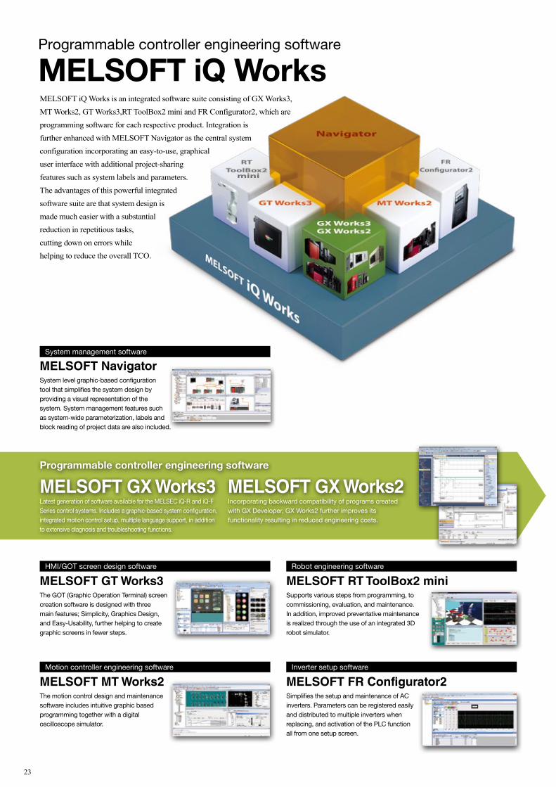
Programmable controller engineering software
MELSOFT iQ WorksMELSOFT iQ Works is an integrated software suite consisting of GX Works3, MT Works2, GT Works3,RT ToolBox2 mini and FR Configurator2, which are programming software for each respective product. Integration isfurther enhanced with MELSOFT Navigator as the central system configuration incorporating an easy-to-use, graphicaluser interface with additional project-sharing features such as system labels and parameters. The advantages of this powerful integrated software suite are that system design is made much easier with a substantial reduction in repetitious tasks, cutting down on errors while helping to reduce the overall TCO.
mini
23
System management software
MELSOFT NavigatorSystem level graphic-based configuration tool that simplifies the system design by providing a visual representation of the system. System management features such as system-wide parameterization, labels and block reading of project data are also included.
Programmable controller engineering software
MELSOFT GX Works3Latest generation of software available for the MELSEC iQ-R and iQ-F Series control systems. Includes a graphic-based system configuration, integrated motion control setup, multiple language support, in addition to extensive diagnosis and troubleshooting functions.
MELSOFT GX Works2Incorporating backward compatibility of programs created with GX Developer, GX Works2 further improves its functionality resulting in reduced engineering costs.
HMI/GOT screen design software
MELSOFT GT Works3The GOT (Graphic Operation Terminal) screen creation software is designed with three main features; Simplicity, Graphics Design, and Easy-Usability, further helping to create graphic screens in fewer steps.
Motion controller engineering software
MELSOFT MT Works2The motion control design and maintenance software includes intuitive graphic based programming together with a digital oscilloscope simulator.
Robot engineering software
MELSOFT RT ToolBox2 miniSupports various steps from programming, to commissioning, evaluation, and maintenance. In addition, improved preventative maintenance is realized through the use of an integrated 3D robot simulator.
Inverter setup software
MELSOFT FR Configurator2Simplifies the setup and maintenance of AC inverters. Parameters can be registered easily and distributed to multiple inverters when replacing, and activation of the PLC function all from one setup screen.

Programmable controller engineering software
MELSOFT iQ WorksMELSOFT iQ Works is an integrated software suite consisting of GX Works3, MT Works2, GT Works3,RT ToolBox2 mini and FR Configurator2, which are programming software for each respective product. Integration isfurther enhanced with MELSOFT Navigator as the central system configuration incorporating an easy-to-use, graphicaluser interface with additional project-sharing features such as system labels and parameters. The advantages of this powerful integrated software suite are that system design is made much easier with a substantial reduction in repetitious tasks, cutting down on errors while helping to reduce the overall TCO.
mini
Space saving
Real-time
Less wiring
Ethernet
Gigabit
Synchronize
Ring
Star
Seamless
General Motion
Safety
Line
Seamless connectivitywithin all levels of automation
The backbone of e-F@ctory, leveraging
connectivity between the shop floor and IT
Extensive visualizationwith advanced dataconnectivityBig Data analytics requires deterministic data collection, which can be realized by incorporating two key features: SLMP*1 that enables seamless connectivity between devices in the IT layer and on the shop floor; and a high-speed, large-capacity 1 Gbps communications network that enables the handling of large-data, such as production, quality and control data between different production processes.
General, motionand safety controlintegrated into one networkCC-Link IE incorporates generic distributed control, synchronous motion control, and safety control enabling safety communications across multiple safety devices, all on the same network. The topology is quite versatile, based on twisted-pair cables, which enables flexibility in system configuration while helping to keep installation cost low.
Comprehensivediagnosis realizinghigher reliabilityDisruptions to the control system are kept to a minimum via comprehensive diagnostics functions, high communications integrity owing to the noiseresistant characteristics of the optical cable, and communication re-routing capabilities made possible as the result of using a ring topology. Also, network errors can be rectified quickly by visualizing the network system image using the engineering software*2, and remotely from a GOT (HMI) directly on the machine or production line.
Seamless datacoordination
MELSEC-QSeries
IT system
(twisted-pair cable)
Production cell A Production cell B Production cell C Production cell D
FA Integrated Engineering SoftwareiQ Works
SCADAsoftware
LAN (Ethernet)
GOT(HMI)
Remote I/Omodule
Inverter MELSEC-LSeries
MELSEC iQ-RSeriesMES interface MELSEC iQ-R
SeriesMELSEC iQ-RSeries
MELSEC iQ-RSeriesSafety CPU
MELSEC iQ-RSeriesC Controller
GOT(HMI)
GOT(HMI)
Servoamplifier
Vision sensorGOT(HMI)
Ethernetadapter
Personalcomputer
interface boardEthernet
Lightcurtain
Safetyswitch
CC-Link IEField−AnyWireASLINKBridge module
Photointerrupter
Photoelectricsensor
(diffuse reflection type)
Proximitysensor
SafetyremoteI/O module
Robot
Servoamplifier
Servoamplifier
MELSEC iQ-FSeries
Enterpriselevel
Controllevel
Fieldlevel
Sensorlevel
Remote I/Omodule
Remote I/Omodule
24

Factory energy optimization with e&eco-F@ctory.
Further strengthening e-F@ctory to reduce total costs encompassing development, production and maintenance through e&eco-F@ctory, which incorporates the visualized control of energy.
Production planning,cost management,
stock management, progress management, schedule management,
quality control, etc.
ERPMES
Energy conservation support devices
B/NET
Electricity equipmentcontroller network
MELSEC-QEnergy measuring module
General-purpose inverter
+ IPM motor
transformer MDU breakerEnergy measuring
module EcoMonitorProEnergy measuring unit
Electricmulti-component
indicator
CC-LinkCC-Link IE
Partnerproduct
Energy-saving DataCollection Server
EcoServer#
Energy Saving
A plant with increased "visualization" is also a plant with increased "energy saving".
In the plant where severe cost management is required, an even greater effort for energy reduction is essential.
Energy-saving solution of e-F@ctory offers an "aggressive energy conservation", which not only reduces the
costs through energy saving but also assesses it totally to pump into new investment.
e&eco-F@ctory proposes precise management of every production equipment or production line and energy
conservation plan based on the life cycle cost of production.
Energy UsageMeasure
Energy UsageVisualize
Energy UsageReduce
Energy UsageManage
25

Factory energy optimization with e&eco-F@ctory.
Further strengthening e-F@ctory to reduce total costs encompassing development, production and maintenance through e&eco-F@ctory, which incorporates the visualized control of energy.
Production planning,cost management,
stock management, progress management, schedule management,
quality control, etc.
ERPMES
Energy conservation support devices
B/NET
Electricity equipmentcontroller network
MELSEC-QEnergy measuring module
General-purpose inverter
+ IPM motor
transformer MDU breakerEnergy measuring
module EcoMonitorProEnergy measuring unit
Electricmulti-component
indicator
CC-LinkCC-Link IE
Partnerproduct
Energy-saving DataCollection Server
EcoServer#
Energy Saving
A plant with increased "visualization" is also a plant with increased "energy saving".
In the plant where severe cost management is required, an even greater effort for energy reduction is essential.
Energy-saving solution of e-F@ctory offers an "aggressive energy conservation", which not only reduces the
costs through energy saving but also assesses it totally to pump into new investment.
e&eco-F@ctory proposes precise management of every production equipment or production line and energy
conservation plan based on the life cycle cost of production.
Energy UsageMeasure
Energy UsageVisualize
Energy UsageReduce
Energy UsageManage
26

Management andmonitoring systems
systems* Comparison of FY1996 and FY2015
Reduction effect
• Reduction in contracted power
1,250kW/year
Comparison of FY1996 and FY2010
• Power cost
Reduced 25%(approx. 100 million yen less)
� Energy-savings results of Fukuyama Works
General assembly line
Inspection ofgeneral assembly
Thermal inspectionand adjustment line
Packaging andshipping process
Mechanicalassembly line
Inspection of mechanical assembly
Parts
Completedproduct
Web-based data server
Data posted on an EMSWebsite accessible from a client PC
Base unit excess count graph by equipment
Individual equipment, base unit, frequent stop graph
10
9.5
9
8.5
8
7.5
7
6.5
6
100%
95%
90%
85%
80%
75%
70%
65%
60%
Contracted power
Contracted power: Reduced by 1,250kW
Power cost: Reduced 25%between 1996 and 2010
After 2011 earthquake, contract maintained at higher cost
Power cost ratio1,000kW
1996 1997 1998 1999 2000 2001 2002 2003 2004 2005 2006 2007 2008 2009 2010 2011 2012 2013
Visualized control with full member participation
Meets Short-Term Measurement needs
I want a fast measurement cycle to measure short-term loads.
Mitsubishi Electric's Fukuyama Works (Fukuyama City, Hiroshima Prefecture) adopted "visible management" in 1997, and now practices aggressive energy conservation efforts. It has realized an economical and ecological eco-factory, and uses its eco expertise to engage in the energy conservation business.Under its policy of "visible energy conservation," it visualizes all aspects of energy usage in the factory as it implements factory-wide energy conservation activities. The knowledge it gains through these activities is incorporated in the development of energy-saving products.
Fukuyama Works makes aggressive energy conservation efforts through "visible management."
Meets Energy-Saving Measurement needs
I want to monitor the power used by each place of equipment, for detailed energy-saving
monitoring.
Key e&eco-F@ctory products, integrating production and quality data and energy data.
The power measuring module is directly attached to the PLC, so there is no need to install any other instruments or connect wiring. There is no need for any major system construction either, so it also saves space.
Slots directly into the PLC
Read the signal from the current sensor on the device breaker, to measure energy consumed by the device. It's easy to grasp power consumption for each PLC unit and manage the standard data for each individual device.
Measure energy consumption simply
Power can be measured only when a specific output signal is on. Power over a period can be measured at two points, to find the standby power consumed while idling or compare power consumed over a certain period.
Easy comparison of power consumption
Record the maximum and minimum values of demand current, voltage, demand power and power factor for each device. Equalization of energy consumption is supported, to identify devices and times of high energy consumption.
Grasp the energy consumption status of a device
Set two measurement factors and monitor their upper and lower limit values. That makes it possible to quickly catch abnormal device status, and to find devices which are using large amounts of energy.
Quickly catch abnormal device statusCurrentsensor
Mitsubishi general-purpose PLCMELSEC-Q Series
Power measuringmodule
GOT 2000
Equipment breaker
Currentinput
Voltageinput
Slots directly into the PLC for simple measurement of diverse energy information!� PLC MELSEC-Q power measuring module
Slots directly into the PLC!
Production equipment
EnergyinformationElectric powerElectric current
Air flow
Productioninformation
Production progressOperation rate
Equipment models
QualityinformationFirst-run rate
Inspection data
MES database server(production, operation, and quality control system)
Production informationQuality informationEnergy information
Web-based energy conservation support system
Visible support of energy conservation activitiesThe Eco Serverl l Web-based data server makes accumulated data
available on the Web via the Intranet in an easy understanding manner,
to promote greater energy conservation efforts.
Electric energy management system
Total support of energy and labor saving efforts in the factoryElectricity, gas, temperature, and other
energy-related data in the factory is recorded
and monitored in detail through a
B/NET network of power distribution
and control equipment.
LAN(Ethernet)
System for standard data management in each work process
Support for reducing standard electric energy data � System improvements are made by measuring the power usage
and production output of each work process and managing standard data based on those measurements.
� "Visible management" is realized by using Intranet Web-based PCs.
Management andmonitoring systems
Screen example
Systemimprovement
New power measurement units join the MELSEC-Q lineup, which continues to revolutionize the site of production. Enabling simple measurement of parameters including current, voltage, power, power factor, and active power, the units integrate production and quality data and energy data, assisting in increasing productivity, saving energy, and implementing preventive maintenance. And because they can be directly slotted into PLCs, they save space, reduce wiring, and lower costs. A range of possibilities are now available, including measurement of the energy used by each piece of production equipment, preventive maintenance of equipment based on real time measurements, and the use of measurements as quality management indicators linked to manufacturing data.
Meets QualityControl needs
I want to detect power supply irregularities
in manufacturing equipment to control product quality.
Meets SimpleInstallation needs
I want simple and smooth installation,
with no program for power measurement.
Meets Preventive Maintenance needs
I want to detect power and current used by
manufacturing equipment and prevent sudden
failures.
Energy Saving
27

Management andmonitoring systems
systems* Comparison of FY1996 and FY2015
Reduction effect
• Reduction in contracted power
1,250kW/year
Comparison of FY1996 and FY2010
• Power cost
Reduced 25%(approx. 100 million yen less)
� Energy-savings results of Fukuyama Works
General assembly line
Inspection ofgeneral assembly
Thermal inspectionand adjustment line
Packaging andshipping process
Mechanicalassembly line
Inspection of mechanical assembly
Parts
Completedproduct
Web-based data server
Data posted on an EMSWebsite accessible from a client PC
Base unit excess count graph by equipment
Individual equipment, base unit, frequent stop graph
10
9.5
9
8.5
8
7.5
7
6.5
6
100%
95%
90%
85%
80%
75%
70%
65%
60%
Contracted power
Contracted power: Reduced by 1,250kW
Power cost: Reduced 25%between 1996 and 2010
After 2011 earthquake, contract maintained at higher cost
Power cost ratio1,000kW
1996 1997 1998 1999 2000 2001 2002 2003 2004 2005 2006 2007 2008 2009 2010 2011 2012 2013
Visualized control with full member participation
Meets Short-Term Measurement needs
I want a fast measurement cycle to measure short-term loads.
Mitsubishi Electric's Fukuyama Works (Fukuyama City, Hiroshima Prefecture) adopted "visible management" in 1997, and now practices aggressive energy conservation efforts. It has realized an economical and ecological eco-factory, and uses its eco expertise to engage in the energy conservation business.Under its policy of "visible energy conservation," it visualizes all aspects of energy usage in the factory as it implements factory-wide energy conservation activities. The knowledge it gains through these activities is incorporated in the development of energy-saving products.
Fukuyama Works makes aggressive energy conservation efforts through "visible management."
Meets Energy-Saving Measurement needs
I want to monitor the power used by each place of equipment, for detailed energy-saving
monitoring.
Key e&eco-F@ctory products, integrating production and quality data and energy data.
The power measuring module is directly attached to the PLC, so there is no need to install any other instruments or connect wiring. There is no need for any major system construction either, so it also saves space.
Slots directly into the PLC
Read the signal from the current sensor on the device breaker, to measure energy consumed by the device. It's easy to grasp power consumption for each PLC unit and manage the standard data for each individual device.
Measure energy consumption simply
Power can be measured only when a specific output signal is on. Power over a period can be measured at two points, to find the standby power consumed while idling or compare power consumed over a certain period.
Easy comparison of power consumption
Record the maximum and minimum values of demand current, voltage, demand power and power factor for each device. Equalization of energy consumption is supported, to identify devices and times of high energy consumption.
Grasp the energy consumption status of a device
Set two measurement factors and monitor their upper and lower limit values. That makes it possible to quickly catch abnormal device status, and to find devices which are using large amounts of energy.
Quickly catch abnormal device statusCurrentsensor
Mitsubishi general-purpose PLCMELSEC-Q Series
Power measuringmodule
GOT 2000
Equipment breaker
Currentinput
Voltageinput
Slots directly into the PLC for simple measurement of diverse energy information!� PLC MELSEC-Q power measuring module
Slots directly into the PLC!
Production equipment
EnergyinformationElectric powerElectric current
Air flow
Productioninformation
Production progressOperation rate
Equipment models
QualityinformationFirst-run rate
Inspection data
MES database server(production, operation, and quality control system)
Production informationQuality informationEnergy information
Web-based energy conservation support system
Visible support of energy conservation activitiesThe Eco Serverl l Web-based data server makes accumulated data
available on the Web via the Intranet in an easy understanding manner,
to promote greater energy conservation efforts.
Electric energy management system
Total support of energy and labor saving efforts in the factoryElectricity, gas, temperature, and other
energy-related data in the factory is recorded
and monitored in detail through a
B/NET network of power distribution
and control equipment.
LAN(Ethernet)
System for standard data management in each work process
Support for reducing standard electric energy data � System improvements are made by measuring the power usage
and production output of each work process and managing standard data based on those measurements.
� "Visible management" is realized by using Intranet Web-based PCs.
Management andmonitoring systems
Screen example
Systemimprovement
New power measurement units join the MELSEC-Q lineup, which continues to revolutionize the site of production. Enabling simple measurement of parameters including current, voltage, power, power factor, and active power, the units integrate production and quality data and energy data, assisting in increasing productivity, saving energy, and implementing preventive maintenance. And because they can be directly slotted into PLCs, they save space, reduce wiring, and lower costs. A range of possibilities are now available, including measurement of the energy used by each piece of production equipment, preventive maintenance of equipment based on real time measurements, and the use of measurements as quality management indicators linked to manufacturing data.
Meets QualityControl needs
I want to detect power supply irregularities
in manufacturing equipment to control product quality.
Meets SimpleInstallation needs
I want simple and smooth installation,
with no program for power measurement.
Meets Preventive Maintenance needs
I want to detect power and current used by
manufacturing equipment and prevent sudden
failures.
Energy Saving
28
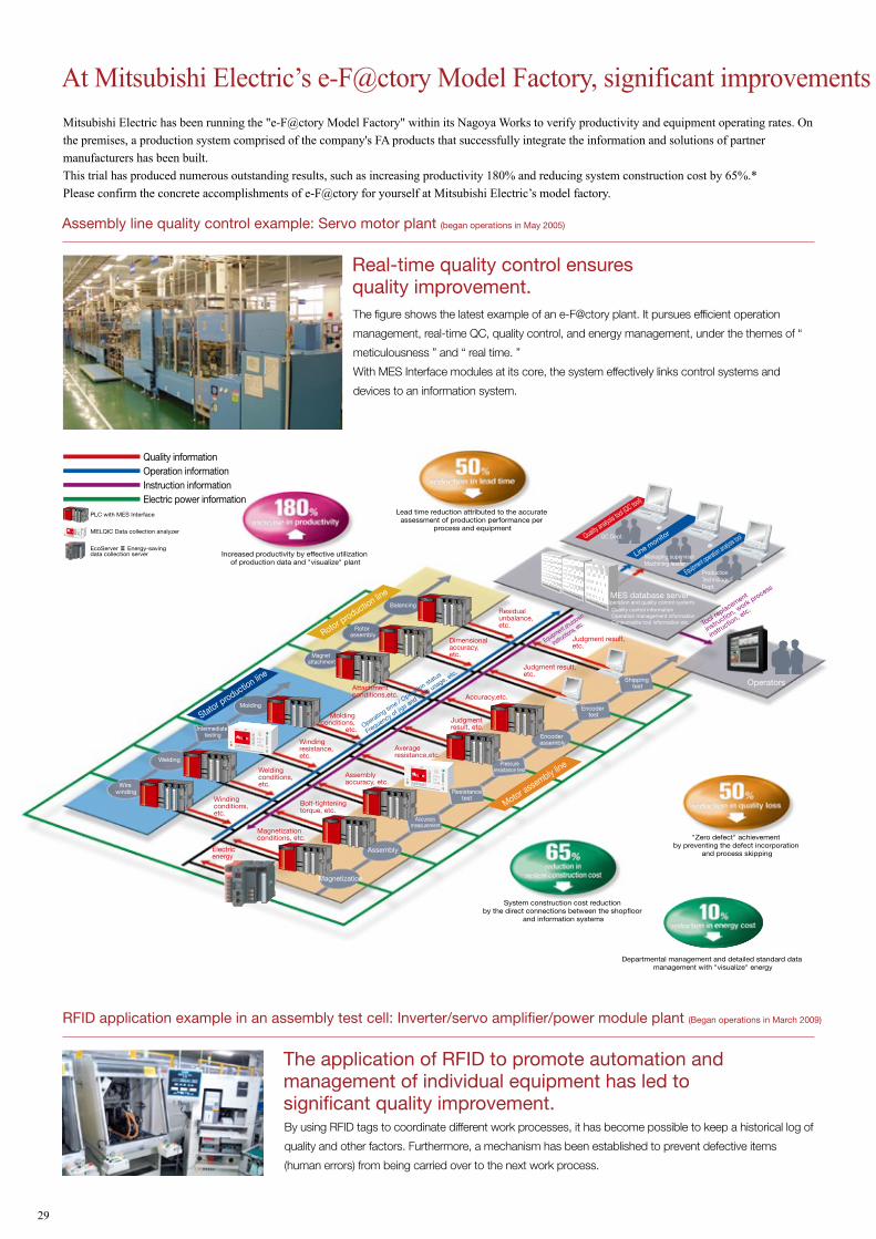
Wire winding
Magnetization
Assembly
Molding
Welding
Balancing
Intermediate testing
Accuracymeasurement
Resistancetest
Encoder assembly
Shipping test
Pressureresistance test
Rotor assembly
Magnet attachment
Windingconditions,etc.
Judgmentresult, etc.
Judgment result,etc.
Judgment result,etc.
Accuracy,etc.
Averageresistance,etc.
Stator production lin
e
Rotor production lin
e
Motor assembly line
Weldingconditions,etc.
Attachmentconditions,etc.
Dimensionalaccuracy,etc.
Residual unbalance, etc.
Windingresistance,etc.
Molding conditions,
etc.Operatin
g time / O
peration st
atus
Frequency of jig
s and to
ols usage, e
tc.
Equipment shutdown
instructions, e
tc. Tool replacement
instructio
n, work process
instructio
n, etc.
Magnetizationconditions, etc.
Electricenergy
Assemblyaccuracy, etc.
Bolt-tighteningtorque, etc.
Encoder test
Quality analysis tool (QC tool)
Line monito
r
Equipment operation analysis tool
Operators
QC Dept.
Managing supervisorMachining leader
ProductionTechnologyDept.
MES database server(Operation and quality control system)
Quality control informationOperation management informationConsumable tool information etc.
Departmental management and detailed standard data management with "visualize" energy
At Mitsubishi Electric’s e-F@ctory Model Factory, significant improvements in productivity and quality, as well as cost reductions, have been achievedMitsubishi Electric has been running the "e-F@ctory Model Factory" within its Nagoya Works to verify productivity and equipment operating rates. On the premises, a production system comprised of the company's FA products that successfully integrate the information and solutions of partner manufacturers has been built. This trial has produced numerous outstanding results, such as increasing productivity 180% and reducing system construction cost by 65%.*Please confirm the concrete accomplishments of e-F@ctory for yourself at Mitsubishi Electric’s model factory.
The figure shows the latest example of an e-F@ctory plant. It pursues efficient operation
management, real-time QC, quality control, and energy management, under the themes of “
meticulousness ” and “ real time. ”
With MES Interface modules at its core, the system effectively links control systems and
devices to an information system.
Real-time quality control ensures quality improvement.
Assembly line quality control example: Servo motor plant (began operations in May 2005)
Realized the small lot/multi-cycle production demanded for electromagnetic switches
by achieving both flexible production using cells and large-volume production using
robots.
A high operating rate, high-quality,
space-saving production system achieved
through the fusion of people and equipment.
Example of introducing a robot assembly cell: Kani Factory electromagnetic switch production line (commenced operation in December 2012)
By pursuing higher productivity per square foot through visualization and analysis/improvement of operating status in real-time, productivity and
quality have been improved.
Example of introducing an operating management system: FA Systems Production Building (commenced operation in May 2014)
Utilizing PLCs manufactured in-house, it is possible to monitor and control all information for the building, including that concerning air-conditioning,
lighting and heat source devices. By forming a network of PLCs on each floor through CC-Link IE, real-time monitoring and operation through display
units and MC Works (SCADA) have been achieved.
Example of introducing an air-conditioning and lighting energy-saving management system: FA Systems Production Building (commenced operation in May 2014)
The application of RFID to promote automation and management of individual equipment has led to significant quality improvement.
RFID application example in an assembly test cell: Inverter/servo amplifier/power module plant (Began operations in March 2009)
Lead time reduction attributed to the accurate assessment of production performance per
process and equipment
By using RFID tags to coordinate different work processes, it has become possible to keep a historical log of
quality and other factors. Furthermore, a mechanism has been established to prevent defective items
(human errors) from being carried over to the next work process.
PLC with MES Interface
Quality informationOperation informationInstruction information
MELQIC Data collection analyzer
Electric power information
EcoServer # Energy-saving data collection server
� Production information � Operating information� Quality information� Error information
Operating rate, stop frequency, pick-up rate, no. of leftover parts, error frequency, etc.
* All numerical values are trial calculated from the results of the e-F@ctory Model Factory at Mitsubishi Electric’s Nagoya Works and based on a computer-free, program-free approach.
Central control panel Air-conditioning control
Local exhaust control
Lighting control
Heat source control
Outdoor-air processing unit control
Floor management sequencer
Display unit
SCADA PLC
Outdoor-air processing unit
Centralized controller Outdoor unit
in energy cost30% reduction
System construction cost reduction by the direct connections between the shopfloor
and information systems
Increased productivity by effective utilization of production data and "visualize" plant
"Zero defect" achievement by preventing the defect incorporation
and process skipping
29

Wire winding
Magnetization
Assembly
Molding
Welding
Balancing
Intermediate testing
Accuracymeasurement
Resistancetest
Encoder assembly
Shipping test
Pressureresistance test
Rotor assembly
Magnet attachment
Windingconditions,etc.
Judgmentresult, etc.
Judgment result,etc.
Judgment result,etc.
Accuracy,etc.
Averageresistance,etc.
Stator production lin
e
Rotor production lin
e
Motor assembly line
Weldingconditions,etc.
Attachmentconditions,etc.
Dimensionalaccuracy,etc.
Residual unbalance, etc.
Windingresistance,etc.
Molding conditions,
etc.Operatin
g time / O
peration st
atus
Frequency of jig
s and to
ols usage, e
tc.
Equipment shutdown
instructions, e
tc. Tool replacement
instructio
n, work process
instructio
n, etc.
Magnetizationconditions, etc.
Electricenergy
Assemblyaccuracy, etc.
Bolt-tighteningtorque, etc.
Encoder test
Quality analysis tool (QC tool)
Line monito
r
Equipment operation analysis tool
Operators
QC Dept.
Managing supervisorMachining leader
ProductionTechnologyDept.
MES database server(Operation and quality control system)
Quality control informationOperation management informationConsumable tool information etc.
Departmental management and detailed standard data management with "visualize" energy
At Mitsubishi Electric’s e-F@ctory Model Factory, significant improvements in productivity and quality, as well as cost reductions, have been achievedMitsubishi Electric has been running the "e-F@ctory Model Factory" within its Nagoya Works to verify productivity and equipment operating rates. On the premises, a production system comprised of the company's FA products that successfully integrate the information and solutions of partner manufacturers has been built. This trial has produced numerous outstanding results, such as increasing productivity 180% and reducing system construction cost by 65%.*Please confirm the concrete accomplishments of e-F@ctory for yourself at Mitsubishi Electric’s model factory.
The figure shows the latest example of an e-F@ctory plant. It pursues efficient operation
management, real-time QC, quality control, and energy management, under the themes of “
meticulousness ” and “ real time. ”
With MES Interface modules at its core, the system effectively links control systems and
devices to an information system.
Real-time quality control ensures quality improvement.
Assembly line quality control example: Servo motor plant (began operations in May 2005)
Realized the small lot/multi-cycle production demanded for electromagnetic switches
by achieving both flexible production using cells and large-volume production using
robots.
A high operating rate, high-quality,
space-saving production system achieved
through the fusion of people and equipment.
Example of introducing a robot assembly cell: Kani Factory electromagnetic switch production line (commenced operation in December 2012)
By pursuing higher productivity per square foot through visualization and analysis/improvement of operating status in real-time, productivity and
quality have been improved.
Example of introducing an operating management system: FA Systems Production Building (commenced operation in May 2014)
Utilizing PLCs manufactured in-house, it is possible to monitor and control all information for the building, including that concerning air-conditioning,
lighting and heat source devices. By forming a network of PLCs on each floor through CC-Link IE, real-time monitoring and operation through display
units and MC Works (SCADA) have been achieved.
Example of introducing an air-conditioning and lighting energy-saving management system: FA Systems Production Building (commenced operation in May 2014)
The application of RFID to promote automation and management of individual equipment has led to significant quality improvement.
RFID application example in an assembly test cell: Inverter/servo amplifier/power module plant (Began operations in March 2009)
Lead time reduction attributed to the accurate assessment of production performance per
process and equipment
By using RFID tags to coordinate different work processes, it has become possible to keep a historical log of
quality and other factors. Furthermore, a mechanism has been established to prevent defective items
(human errors) from being carried over to the next work process.
PLC with MES Interface
Quality informationOperation informationInstruction information
MELQIC Data collection analyzer
Electric power information
EcoServer # Energy-saving data collection server
� Production information � Operating information� Quality information� Error information
Operating rate, stop frequency, pick-up rate, no. of leftover parts, error frequency, etc.
* All numerical values are trial calculated from the results of the e-F@ctory Model Factory at Mitsubishi Electric’s Nagoya Works and based on a computer-free, program-free approach.
Central control panel Air-conditioning control
Local exhaust control
Lighting control
Heat source control
Outdoor-air processing unit control
Floor management sequencer
Display unit
SCADA PLC
Outdoor-air processing unit
Centralized controller Outdoor unit
in energy cost30% reduction
System construction cost reduction by the direct connections between the shopfloor
and information systems
Increased productivity by effective utilization of production data and "visualize" plant
"Zero defect" achievement by preventing the defect incorporation
and process skipping
30

Collaborating with partners to ensure thorough shop floor optimization.
In order to provide optimal solutions that match customers' needs, e-F@ctory is designed to enable
collaboration with many partner manufacturers. Mitsubishi Electric is proud its highly evaluated products
in the FA field. Together with the partners participating in the e-F@ctory Alliance FA partner program
promoted by Mitsubishi Electric, the aim is “total cost reduction” for all aspects of customer
development, production and maintenance.
Solutions are wide-ranging, including improving facility operation efficiency, shortening lead time,
improving quality and reducing costs.
Firmly linking partner companies, e-F@ctory Alliance offers solutions for diversified needs.The e-F@ctory Alliance is a FA manufacturer partnering program that strongly links the connection compatibility of
Mitsubishi Electric FA equipment utilizing excellent software and machinery offered by partners, thereby enabling systems to be
built by systems integration partners and the proposal of optimal solutions to customers.
Combining Mitsubishi Electric FA equipment and other products, systems integrators propose systems solutions for everything from shop floors to information systems.
Create entire production systems.Realize advanced systems integration.
Utilizing information-sharing products and technologies such as Mitsubishi Electric's EZSocket and SLMP, vendors develop and propose excellent application software and drivers that ensure the connection compatibility of Mitsubishi Electric FA equipment.
Develop applications software that further enhance connection compatibility of Mitsubishi Electric FA equipment.
Manufacturers proposing peripheral equipment that is easy to connect with Mitsubishi Electric FA equipment and is easier to use.
Propose Mitsubishi Electric FA equipment and other machinery with superior compatibility.Realize improved systems construction and maintenance.
SystemIntegration
PartnerCAD/PLM SCADA
Design support/monitoring systems
ERPMES
Informationsystems Software
Partner
AC servo MDU circuitbreaker
Powermeasurement module
Energy measuring unitInverterRobot
Field equipment
Computerized numericalcontroller (CNC)
Motion controllers
Controller
Robot controller
DevicePartner
Actuator Vision system Sensor RFID Laser marker Recorder
Display (HMI)
PLCs
Electronic multi-componentindicator
Production line Energy-saving Instrument
Traceability Productionmanagement
Preventivemaintenance
Safety Quality control Renewal
MES SCADA SCM
CAD/PLM ERP MRP
Data logger FA simulator APS
Sensor Actuator Communicationcable
Visualizationsystem RFID Analyzer
Laser marker RecorderRelay terminal
block
SystemIntegration
Partner
SoftwarePartner
DevicePartner
31

Collaborating with partners to ensure thorough shop floor optimization.
In order to provide optimal solutions that match customers' needs, e-F@ctory is designed to enable
collaboration with many partner manufacturers. Mitsubishi Electric is proud its highly evaluated products
in the FA field. Together with the partners participating in the e-F@ctory Alliance FA partner program
promoted by Mitsubishi Electric, the aim is “total cost reduction” for all aspects of customer
development, production and maintenance.
Solutions are wide-ranging, including improving facility operation efficiency, shortening lead time,
improving quality and reducing costs.
Firmly linking partner companies, e-F@ctory Alliance offers solutions for diversified needs.The e-F@ctory Alliance is a FA manufacturer partnering program that strongly links the connection compatibility of
Mitsubishi Electric FA equipment utilizing excellent software and machinery offered by partners, thereby enabling systems to be
built by systems integration partners and the proposal of optimal solutions to customers.
Combining Mitsubishi Electric FA equipment and other products, systems integrators propose systems solutions for everything from shop floors to information systems.
Create entire production systems.Realize advanced systems integration.
Utilizing information-sharing products and technologies such as Mitsubishi Electric's EZSocket and SLMP, vendors develop and propose excellent application software and drivers that ensure the connection compatibility of Mitsubishi Electric FA equipment.
Develop applications software that further enhance connection compatibility of Mitsubishi Electric FA equipment.
Manufacturers proposing peripheral equipment that is easy to connect with Mitsubishi Electric FA equipment and is easier to use.
Propose Mitsubishi Electric FA equipment and other machinery with superior compatibility.Realize improved systems construction and maintenance.
SystemIntegration
PartnerCAD/PLM SCADA
Design support/monitoring systems
ERPMES
Informationsystems Software
Partner
AC servo MDU circuitbreaker
Powermeasurement module
Energy measuring unitInverterRobot
Field equipment
Computerized numericalcontroller (CNC)
Motion controllers
Controller
Robot controller
DevicePartner
Actuator Vision system Sensor RFID Laser marker Recorder
Display (HMI)
PLCs
Electronic multi-componentindicator
Production line Energy-saving Instrument
Traceability Productionmanagement
Preventivemaintenance
Safety Quality control Renewal
MES SCADA SCM
CAD/PLM ERP MRP
Data logger FA simulator APS
Sensor Actuator Communicationcable
Visualizationsystem RFID Analyzer
Laser marker RecorderRelay terminal
block
SystemIntegration
Partner
SoftwarePartner
DevicePartner
32

Factory Automation Global websiteMitsubishi Electric Factory Automation provides a mix of services to support its customers worldwide. A
consolidated global website is the main portal, offering a selection of support tools and a window to its local
Mitsubishi Electric sales and support network.
■ From here you can find:
• Overview of available factory automation products• Library of downloadable literature• Support tools such as online e-learning courses,
terminology dictionary, etc.• Global sales and service network portal• Latest news related to Mitsubishi Electric factory
automation
Mitsubishi Electric Factory AutomationGlobal website:
www.MitsubishiElectric.com/fa
Online e-learning
■ Beginner levelDesigned for newcomers to Mitsubishi Electric Factory Automation products gaining a background of the fundamentals and an overview of various products related to the course.
■ Basic to Advanced levelsThese courses are designed to provide education at all levels. Various different features are explained with application examples providing an easy and informative resource for in-house company training.
An extensive library of e-learning courses covering the factory automation product range has been prepared.
Courses from beginner to advanced levels of difficulty are available in various languages.
33
Microsoft, Windows, Excel are registered trademarks of Microsoft Corporation in the United States and other countries.ETHERNET is a trademark of Xerox Corp.SD/SDHC logo is a trademark of SD-3C, LLC.MODBUS is a registered trademark of Schneider Electric USA, Inc.All other company names and product names used in this document are trademarks or registered trademarks of their respective companies.
Precautions before use
This publication explains the typical features and functions of the products herein
and does not provide restrictions or other information related to usage and module
combinations. Before using the products, always read the product user manuals.
Mitsubishi Electric will not be held liable for damage caused by factors found not to
be the cause of Mitsubishi Electric; opportunity loss or lost profits caused by faults in
Mitsubishi Electric products; damage, secondary damage, or accident compensation,
whether foreseeable or not, caused by special factors; damage to products other
than Mitsubishi Electric products; or any other duties.
For safe use
• To use the products given in this publication properly, always read the relevant manuals before beginning operation.
• The products have been manufactured as general-purpose parts for general industries, and are not designed or manufactured to be incorporated in a device or system used in purposes related to human life.
• Before using the products for special purposes such as nuclear power, electric power, aerospace, medicine or passenger-carrying vehicles, consult with Mitsubishi Electric.
• The products have been manufactured under strict quality control. However, when installing the products where major accidents or losses could occur if the products fail, install appropriate backup or fail-safe functions in the system.

34
YOUR SOLUTION PARTNER
Automation solutions
Mitsubishi Electric offers a wide range of automation equipment from PLCs and HMIs to
CNC and EDM machines.
A NAME TO TRUSTSince its beginnings in 1870, some 45 companies use the Mitsubishi name, covering a spectrum of finance, commerce and industry.
The Mitsubishi brand name is recognized around the world as a symbol of premium quality.
Mitsubishi Electric Corporation is active in space development, transportation, semi-conductors, energy systems, communications and information processing, audio visual equipment and home electronics, building and energy management and automation systems, and has 237 factories and laboratories worldwide in over 121 countries.
This is why you can rely on Mitsubishi Electric automation solution - because we know first hand about the need for reliable, efficient, easy-to-use automation and control in our own factories.
As one of the world’s leading companies with a global turnover of over 4 trillion Yen (over $40 billion), employing over 100,000 people, Mitsubishi Electric has the resource and the commitment to deliver the ultimate in service and support as well as the best products.
Medium voltage: VCB, VCC
Power monitoring, energy management
Compact and Modular Controllers
Inverters, Servos and Motors
Visualisation: HMIs
Numerical Control (NC)
Robots: SCARA, Articulated arm
Processing machines: EDM, Lasers, IDS
Transformers, Air conditioning, Photovoltaic systems
Low voltage: MCCB, MCB, ACB
* Not all products are available in all countries.

Mitsubishi Electric Corporation Nagoya Works is a factory certified for ISO 14001 (standards for environmental management systems) and ISO 9001 (standards for quality assurance management systems).
Country/Region Sales office Tel/FaxUSA MITSUBISHI ELECTRIC AUTOMATION, INC.
500 Corporate Woods Parkway, Vernon Hills, IL 60061, U.S.A.Tel : +1-847-478-2100Fax : +1-847-478-2253
Mexico MITSUBISHI ELECTRIC AUTOMATION, INC. Mexico BranchMariano Escobedo #69, Col. Zona Industrial, Tlalnepantla Edo. Mexico, C.P.54030
Tel : +52-55-3067-7500
Brazil MITSUBISHI ELECTRIC DO BRASIL COMÉRCIO E SERVIÇOS LTDA.Avenida Adelino Cardana, 293, 21 andar, Bethaville, Barueri SP, Brazil
Tel : +55-11-4689-3000Fax : +55-11-4689-3016
Germany MITSUBISHI ELECTRIC EUROPE B.V. German BranchMitsubishi-Electric-Platz 1, 40882 Ratingen, Germany
Tel : +49-2102-486-0Fax : +49-2102-486-1120
UK MITSUBISHI ELECTRIC EUROPE B.V. UK BranchTravellers Lane, Hatfield, Hertfordshire, AL10 8XB, U.K.
Tel : +44-1707-28-8780Fax : +44-1707-27-8695
Ireland MITSUBISHI ELECTRIC EUROPE B.V. Irish BranchWestgate Business Park, Ballymount, Dublin 24, Ireland
Tel : +353-1-4198800Fax : +353-1-4198890
Italy MITSUBISHI ELECTRIC EUROPE B.V. Italian BranchCentro Direzionale Colleoni-Palazzo Sirio Viale Colleoni 7, 20864 Agrate Brianza(Milano) Italy
Tel : +39-039-60531Fax : +39-039-6053-312
Spain MITSUBISHI ELECTRIC EUROPE, B.V. Spanish BranchCarretera de Rubí, 76-80-Apdo. 420, 08190 Sant Cugat del Vallés (Barcelona), Spain
Tel : +34-935-65-3131Fax : +34-935-89-1579
France MITSUBISHI ELECTRIC EUROPE B.V. French Branch25, Boulevard des Bouvets, 92741 Nanterre Cedex, France
Tel : +33-1-55-68-55-68Fax : +33-1-55-68-57-57
Czech Republic MITSUBISHI ELECTRIC EUROPE B.V. Czech BranchAvenir Business Park, Radlicka 751/113e, 158 00 Praha5, Czech Republic
Tel : +420-251-551-470Fax : +420-251-551-471
Poland MITSUBISHI ELECTRIC EUROPE B.V. Polish Branchul. Krakowska 50, 32-083 Balice, Poland
Tel : +48-12-347-65-00Fax : +48-12-630-47-01
Sweden MITSUBISHI ELECTRIC EUROPE B.V. (Scandinavia)Fjelievägen 8, SE-22736 Lund, Sweden
Tel : +46-8-625-10-00Fax : +46-46-39-70-18
Russia MITSUBISHI ELECTRIC (RUSSIA) LLC St. Petersburg BranchPiskarevsky pr. 2, bld 2, lit “Sch”, BC “Benua”, office 720; 195027 St. Petersburg, Russia
Tel : +7-812-633-3497Fax : +7-812-633-3499
Turkey MITSUBISHI ELECTRIC TURKEY A.Ş Ümraniye BranchSerifali Mahallesi Nutuk Sokak No:5, TR-34775 Umraniye/Istanbul, Turkey
Tel : +90-216-526-3990Fax : +90-216-526-3995
UAE MITSUBISHI ELECTRIC EUROPE B.V. Dubai BranchDubai Silicon Oasis, P.O.BOX 341241, Dubai, U.A.E.
Tel : +971-4-3724716Fax : +971-4-3724721
South Africa ADROIT TECHNOLOGIES 20 Waterford Office Park, 189 Witkoppen Road, Fourways, South Africa
Tel : +27-11-658-8100Fax : +27-11-658-8101
China MITSUBISHI ELECTRIC AUTOMATION (CHINA) LTD.No.1386 Hongqiao Road, Mitsubishi Electric Automation Center, Shanghai, China
Tel : +86-21-2322-3030Fax : +86-21-2322-3000
Taiwan SETSUYO ENTERPRISE CO., LTD.6F, No.105, Wugong 3rd Road, Wugu District, New Taipei City 24889, Taiwan
Tel : +886-2-2299-2499Fax : +886-2-2299-2509
Korea MITSUBISHI ELECTRIC AUTOMATION KOREA CO., LTD.7F-9F, Gangseo Hangang Xi-tower A, 401, Yangcheon-ro, Gangseo-Gu, Seoul 07528, Korea
Tel : +82-2-3660-9530Fax : +82-2-3664-8372
Singapore MITSUBISHI ELECTRIC ASIA PTE. LTD.307, Alexandra Road, Mitsubishi Electric Building, Singapore 159943
Tel : +65-6473-2308Fax : +65-6476-7439
Thailand MITSUBISHI ELECTRIC FACTORY AUTOMATION (THAILAND) CO., LTD.12th Floor, SV.City Building, Office Tower 1, No. 896/19 and 20 Rama 3 Road, Kwaeng Bangpongpang, Khet Yannawa, Bangkok 10120, Thailand
Tel : +66-2682-6522Fax : +66-2682-6020
Vietnam MITSUBISHI ELECTRIC VIETNAM COMPANY LIMITED Hanoi Branch6th Floor, Detech Tower, 8 Ton That Thuyet Street, My Dinh 2 Ward, Nam Tu Liem District, Hanoi, Vietnam
Tel : +84-4-3937-8075Fax : +84-4-3937-8076
Indonesia PT. MITSUBISHI ELECTRIC INDONESIAGedung Jaya 11th Floor, JL. MH. Thamrin No.12, Jakarta Pusat 10340, Indonesia
Tel : +62-21-3192-6461Fax : +62-21-3192-3942
India MITSUBISHI ELECTRIC INDIA PVT. LTD. Pune BranchEmerald House, EL-3, J Block, M.I.D.C., Bhosari, Pune-411026, Maharashtra, India
Tel : +91-20-2710-2000Fax : +91-20-2710-2100
Australia MITSUBISHI ELECTRIC AUSTRALIA PTY. LTD.348 Victoria Road, P.O. Box 11, Rydalmere, N.S.W 2116, Australia
Tel : +61-2-9684-7777Fax : +61-2-9684-7245
HEAD OFFICE: TOKYO BLDG., 2-7-3, MARUNOUCHI, CHIYODA-KU, TOKYO 100-8310, JAPAN
www.MitsubishiElectric.com
L(NA)16012E-E 1606[IP]New publication, effective Jun. 2016.
Specifications are subject to change without notice.