mitsubishi cyclo drive 6000 series
DESCRIPTION
Thcc1ttulih,nrcrye MTTSUBISHIELECTRICAUTOMATION(THAILAND)CO.' LTD. MITSUBISHI ELECTRIC tj 'il ' .:;: i,, -r . ll 'i 'r'!1'ertsx.r".*n. liTRANSCRIPT

MTTSUBISHI ELECTRIC AUTOMATION (THAILAND) CO.' LTD.
...ABSORB 5OOo/o SHOCK LOADWITHOUT DAMAGE!
&1}&$J' ClSJeO, O{C,},*g}FeJlV Pee ekkcwK Ls&rs
y-&U'&! &S$,,*C&FJ
MITSUBISHIELECTRIC
'r'!1'ertsx.r".*n.
.
ll 'i
tji,,
-r
'il' .:;:
l i
Thc c1ttulih,nrcrye

. , ,OEIC PRODUCT FEATURES AND BENEFITS
5OO% OVER SHOCK LOADThis photoelastic experiment clearly shows a number of cycloidal teethconstantly in contact with the rollers, thereby distributing the loads.Furthermore, the stress lines clearly shows no stress concentration in theroot area. Unlike involute teeth, CYCLO teeth can not break.
In the involute gear system, only one or two teeth areengaged and are carrying the full load. There is a highstress concentration in the root area of the teeth. Teethcan break under shock load and overload.
material are used to make the Cycloidal discs and rollers. Output shafts are madein Japan ensuring worldwide uniformity and quality.
High qual i ty Nickel Chrome Bear ing Steelfrom forged steel. All parts manufactured
COMPACT IN SIZEThe CYCLO can offer high ratio in as ingle stage reduct ion (119/1 ) therebymaking the reducer size more compactand l ightweight .
WIDE RATIO RANGECYCLO have the ratio ranoe availablef rom 6:1 to 1,000,000:1
Ring gear pins and rollers
Eccenttric cam and
HIGH EFFICIENCYThe CYCLO can offer ratio up to 119:1on a single stage reduction at the samet i m e m a i n t a i n i n g h i g h e f f i c i e n c ythroughout.
LOW NOISEA s a l l p a r t s a r e r o l l i n g . C Y C L Ogenerate the lowest noise level.
NO CATASTROPHIC FAILUREDue to the fact that the Cycloidal teethcan not break, there is no chance forthe CYCLO to experience catastrophic( immediate) fa i lure.
EASE OF MAINTENANCEAs the d i sassemb led un i t shows ,Cyclodrive can be easily disassembledand assembled for maintenance usingonly simple hand tools. Furthermore,the number of par ts are less thanconvent ional involute gear systemthereby enabling saving on sqare partsCOSIS.

g ADVANTAGE OF CYCLO DR|VE
The unique CYCLO speed reducing system is based on an ingeniously simple principle offering many benefits to thedesigner and user of power transmission drives. Basically, the speed reducer has only three major moving parts:
Slow speed shaftRing gear pins androllers
Cycloid disc
Slow speed shaftpins
il + (J-Hish speed shaft
I
LEccentric cam
o High speed input shaft withintegrally mounted eccentriccam and roller bearingaqsembly
o Cycloid discs,o Slow speed shaft assembly.
As the eccentric cam rotates, it rolls the cycloid discs around the internal circumference of the stationary ring gear. Theresulting action is similar to that of a wheel roll ing around the inside of a ring. As the wheel (cycloid disc) travels in aclockwise path around the ring (ring gear housing), the wheel itself turns slowly on its own axis in a counter-clockwisedirection. In the CYCLO system the cycloidal profi le around the outer edge of the disc engages progressively with the rollersof the fixed ring gear housing to produce a reverse rotation at reduced speed. For each complete revolution of the highspeed shaft the cycloid disc turns one cycloidal tooth pitch in the opposite direction. In general, there is one less cycloidatooth around the disc than there are pins in the fixed ring gear housing, which results in reduction ratios being numericallyequal to the number of cycloidal teeth on the disc. (Note: On some ratios, there are two less teeth per cycloid disc than thereare pins in the ring gear housing.) The reduced rotation ol the cycloid discs is transmitted to the slow speed shaft by meansof drive pins and rollers which engage with holes located around the middle of each disc. Normally a two disc system is usecwith a double eccentric cam which increases the torque capacity and offers an exceptionally smooth vibration{ree drive.
HELICAL GEARS
TWO-THIRDS OF TEETH IN FULLCONTACT ALL TIME
CYCLO SPEED REDUCERManV teeth share the shock ol overload
ONLY 1 OR 2 TEETH IN CONTACT
d""L} -,.,.'.-
) = : ( < (L ^ 5 J
(^ ^_) "fd(-,/.-W
CONVENTIONAL HELICAL GEAR.1 or 2 teeth absorb the entire shock of overload.
SLIDING FRICTION MOTION
SHOCK LOAD ONLY 2OO%
q-|re-q--ar$<-'\
<ffifd.Y@ets6--'@'
COMPACT SIZEReduction ratios lrom 6:1 to 119:1are available for the single stage.
SIZE BIGGER ATTHE SAME RATINGAND RATIO
Normal ratio of helicai gear is 5 or 6
"rr"%,-\t
I

NOMENCLATURE OF GEARMOTORS
05
l(w, H P .
05 0.4 0.5t r . / o
2 1 . 5 z
3 2.2 3J . l 5
I 5 .5 7 .51 0 7.5 1 0
o
=
Capacity Range 1l2HP 4P-10HP 4P Both Horizontal and Vertical TvoeEnclosure Totallv Enclosed Fan Cooled TvDeDeoree of Protection tP55Power Source 2201380-41 5V 50H z. 22O / 44O 6OHzFrame Meterial Steel PlateInsulation Class FRatinq ContinuousConnection Tvoe Terminal Block f6 Leadsl
Connection Diagram
Lubrimlion Method Grease Lubrication (Frame Size 6060-6125) Oil Lubrication (Frame Size 6135^-€175)Speed Reduction Method Internal planetarv oear mechanism with trochoidal curved toolh profi le
Ambient Temoerature -2O'C-+4O'C
Ambient Humidity 957" RH or lessAbove Sea L6vel 1000 m. or lessEnvironment No burstino / erosive oas or vaDor
Recommended Grease
Ambientlemperature
fc)
ModelMaintenance-free series Oher grease model
Shell Cosmo Oil Shell
-1 0-50 ALVANIAGREASE RA COSMO GREASEDYNAMAX SH No.2
ALVANIA GREASE 2
Grease Quantity (litre)
Recommended Oil
Framo slze 608tr 609f 611trReduction
portion Ity ofgrease (g) 65 90 140 200 330
Slow speed shallbearing portion Oty ot grease (g 70 1 0 0 't00 90 120
Ambi6ntlomperatuK
fc)
NissskiMitsubishi
ldemltsuKosan Gulf Oil Esso Oil Mobil Oil Shell Oil BP OiI
-1 0-5Bonnock
M68
Daphe SuperGear Oil
68
:P LubricanHD 68
SpartanEP 68
Mobil Gear626
:tso vG 68)
Omala Oil68
EnergolGH-XP 68
0-35Bonnock
M'100, '150
)aphe SuperGear Oil'100, 150
:P LubricanHD 1OOHD 150
SpartanEP 1OOEP 150
Mobil Geal627 629(rsovG100,1s0)
Omala Oil1 0 0 , 1 s 0
EnergolGR-XP lOOGR.XP 150
30-50Bonnock
M220-460
:P LubricanHD 220HD 320HD 460
SpartanEP 220EP 320EP 460
Mobil Gear630 632633 634(rsovG
220-460)
Omala Oil220 320
460
EnergolGR-XP 220GR.XP 320GR-XP 460
OilQuant i ty ( l i t re)
.ram6 giz€ 6'13tr 614tr 618tr 617tr
Horizontalshaft
o.7 o.7 1 . 4 '1 .9
Verticalshatt
1 . 1 1 . 1 1 . 0 1 . 9

g STANDARD STOCK OF GEARMOTOR
(hrs/day) AGMA CYCLO AGMA CYCLO AGMA CYCLO
0.5 0.50 0.50 0.80 0.80 1.25 1.20
3 0.80 0.80 l .oo 1 .00 1 . 5 0 1.35
1 0 1 . 0 0 1.00 1 . 2 5 1.20 1 . 7 5 1.50
24 1 . 2 5 | .20 1 .50 1.35 2.00 1.60
In case of short t ime intermittent operations, it may be possible to usea smaller than normal model. but olease consult us in such an event.
ln case of frequent starVstop operations or under heavy shock conditions,special reinforcements and other measures may be required, in which eventwe should be consulted.
Actual output speed (rpm) may vary slightly from output rpm shown.Please notify the factory if actual output rpm is required.
250 cNHl\405-6080-6 1.48 cNHM1.6090-6 '1,53 cNHt\42.6100.6 1 .57 cNH[,43-6110-6 '1.6 1 CNH|\il5-6120-6 1.37 cHHtvtS-6130-6 1 7 1 cHHMI 0-61 35-6
136 cNHM05-6080-111.48 cNHMI-6090-11 1.53 cNHM2-6100-'111.57 cNHM3-6110-11 1.61 cNHM5-6120-11 1.37 cHHMS-6130-11 1.71 cHHM10"6135.'11
100 CNHlil05-6080-1 5 1 .44 cNHMI -6090-1 5 1 .53 cNHt!t2-6100-1 5 1 .57 cNHt\43-6110-15 CNHI\,15-6120-151.37 cHHMS-6130-15 1 4 1 cHHt\,,110-6135-151.20
88 cNHM05-6080-17 1.48 cNHMI-6090-'t7 1 .53 cNHM2-6100-17 r.33 cNHMS-6110-1 7 1 .45 cNHMS-6125-17 '1.53 cHHMS-6135-17 L J I cHHM'10-6145-171.60
7'l cNHl,l05-6085-21 1.38 cNHMI-6095-21 2.01 cNHM2-6105'21 1.52 cNHM3-6115-21 cNHM5-6125-21 1.29 cHHMS-6135-21 1.22 cHHt l0-6145-21 1.27
60 cNHM05-6090-25 1.68 cNHMI-61 00-25 1.69 cNHM2-6120-25 2.06 cNHMS-6120-251.40 cHHM5-6135-25 1.55 cHHMS-6145-25 1.44 cHHM10-61 65-25 '1.79
5'1.7 cNHM05-6090-291.56 cNHt\4'1 -6 r00-29 1 . 6 1 cNHM2-61 20-29 1 . 9 1 cNHl/3-6125"29 1.58 cHHt\45-6135-291 . 3 1 cHHMS-6145-29 1.37 cHHMl0-6'!65-29 1.52
43 cNHM05.6090.351.53 cNHM1.6105-35 '1.60 cNHM2-6120-35 1.58 cNHM3"6125"35 '1.3 1 cHHMS-6145"351,69 cHHMS-6160-35 1.46 cHHM10-6165-351.28
34.9 cNHtv0S-6095-431 . 5 1 cNH t\,11-6105-431.44 cNHM2-6125-43 1.56 cHHMS-6135-43 1 . 5 2 cHHM5-6145-43 1 . 2 6 cHHMS-61 65"43 1.42 cH Hl\41 0-6175-43 t . c I
250 cNVM05-6080-6 '1.48 cNVtvll-6090-6 1.53 cNVM2-6100-6 1.57 cNVt\43.6110-6 L O I cNVM5-6120-6 1.37 cwMS-6130-6 1 . 7 1 cvvMl0-6135-6
136 oNVM05-6080-1 1 1.48 oNVMI -6090-1 1 1 .53 CNVM2-6100-1 1 1.57 CNVM3-6110-1 1 1 .61 CNVM5-6120-1 1 1.37 cwMS-6130-111.71 cwM10.6135-11t . c l
100 cNVM05-6080-'t51 .48 cNVMt-6090-15 1.53 cNVtv2-6100-15 1.57 CNVM3-611 0-1 5 1 .61 cNVM5-6120-15 cvvMs-6130-1 5 1 . 4 1 cvvlvll 0-6135-1 5 1 .20
88 cNVM05-6080-171.48 oNVM1.6090"17 1.53 cNVM2.6100-1 7 1.33 CNVMS-61 10-17 1.45 cNVM5-6125-17 1.53 cwMS-6135-17 t . 5 l cwM10-6145-17 1.60
71 cNVl/05-6085-21 1.38 cNVt\,41-6095-212.01 cNVtv2-6105-211.52 cNVlv3-6115-21 1 . 4 1 cNVM5-6125-21 1.29 cwtvS-6135-211.22 cvvMl 0-61 45-21 1.27
60 cNVM05-6090-251.68 cNVM1.61 00.25 1.69 cNVM2.6120-25 2.06 cNVt\43.6120.251.40 cw[,t5-6135.25 1.55 cwMS-6145-251.44 cvvl/10-6165-251.79
51.7 CNV[/]05-6090-29'1.56 cNVt\4'1 -6100-29 L O I cNVM2-6120-29 cNVt\.43-6125-291.58 cwt!15-6135-29 '1 .31 cvvMS-6145-291.37 cvvt\r1 0-6165-29 | .52
43 cNVM05.6090-351.53 cNVrvr1.6105-351.60 cNVM2-6120-35 1.58 cNVM3.6125-35 1.31 cwMs"6145.35 1,69 cvvM8.6160-351.46 cwlv10-6165-351.28
34.9 cNVM05-6095-43 cNVt!|1-6105-43 1 4 4 cNVM2-6125-43 L C O CW|\il3-6135-43 1.52 cwl\,15-6145-43 1 . 6 cvvMS-6'1 65-43 1.42 cwt\410-6175-43

ffii DIMENSION
L
Fig 1. Type CNHM (0.5-2 HP)(Grease Lubrication)
Fig 2. Type CNHM(Grease Lubrication)
: _ l
Fig 3. Type CHHM(Oil Lubrication)
28h6 90 013
38h6 90 016
r ll - l
. l ' 1 . , )l i i : : : I t ,
i l i \
- :- i i ' I
l i i. : , ._
, ---Lf]\ :ri n / " l. - -L : -
Fig 4. Type CNVM (0.5-2 HP)(Grease Lubrication)
Fig 5. Type CNVM(Grease Lubrication)
Fig 6. Type CVVM(Oil Lubrication)
Fig 7. Type CVVM(Oil Lubrication with circulat ing pump)
cNVM05-608 E 94 160 134 1 1 0 48 9 3 4 I l 22n6v" 35 6 6 3 .5 M6 t o 147 .6 1 3 8 297 5 4
cNVM05.609 Ll 94 1 6 0 134 1 1 0 48 9 3 A 1 1 107 2gh6 90 013 35 d 7 4 M8 20 147.6 138 297 54
CNVM1.609U 16.1 ,6 144 329 7
cNVMI-610 L l 1 0 8 160 134 1 1 0 48 I 3 4 1 1 107 28h6 90 013 35 8 7 4 M8 20 t o t . o 44 343 1 9 4cNVM2-6101--l 183 .6 56 378 25cNVM3-611 L_l 112 210 180 140 58 1 1 4 1 1 I t b 32h6 yo o 45 1 0 I 5 M8 20 207 69 4 1 8 30 5
cNVM2-61 2 Ll117 210 1 8 0 140 69 I J 4 6 1 l 137 38h6 90 016 55 1 0 8 5 tv8 20
183 .6 56 387 28 4
cNVM3-612n 207 69 434 325
cNvM5.612 L 228 80 444 36
cwM3-613 [l
164 260 230 200 76 t c 4 6 1 1 152 l J O 50h6 90.016o t 1 4 I 5 . 5 M 1 0 1 8
207 69 488 64
6CVVM5.613 LJ 228 80 492 68
cvvM8.613 Ll 266 213 541 78
cwMl0-613 L-.1 266 541 85
cvvM5-614 L l164 260 230 200 96 I J 4 6 I i 152 233 50h6 90 01 6 8 1 1 4 9 5 .5 M l 0 1 8
228 1 8 0 492 726CVVM8.614 E 266 1 t o 54'l 82
cwM10-614 L_.r 266 2 ' t 3 541 89
cvvMS-616 Ll219 340 3 1 0 270 89 20 6 200 60h6 90.01e80 1 8 1 1 7 M l 0 1 8 266 2' t3 596 107
7cwM10.616 L 266 z t J 596 1 1 3
cvvM10-617 L_.1258 400 360 3 1 6 94 22 5 8 1 4 222 225 70h6 90 01. 84 20 7 .5 M ] 2 24 266 213 640 1 5 5 7
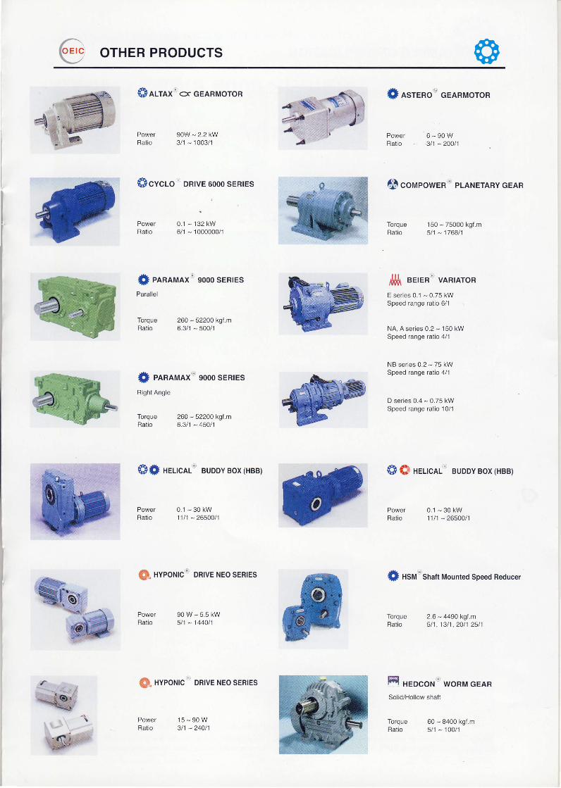
@ OTHER PRODUCTS
Sarrnx" s cEARMoroR
90w - 2.2 kw3/1 - 1003/1
Scvcuo' DRrvE 6000 sERrEs
0.1 - 132 kw6n - 1 000000n
0 . 1 - 3 0 k w11t1 - 26500t1
9 0 w - 5 . 5 k w5t1 - 1440t1
1 5 - 9 0 W3t1 - 240/1
{} lsrenot cEARMoroR
PowerRatio
PowerRatio
6 - 9 0 W3t'l - 200t1
PowerRatio
6 coupowERnr PLANETARY GEAR
Torque 150 - 75000 kgf.mRatio 511 - 176811
ffi eerent vARrAToRE ser ies 0.1 - 0.75 kWSpeed range ratio 6/1
NA, A series 0.2 - 150 kWSpeed range ratio 4/1
NB series 0.2 - 75 kWSpeed range ratio 4/1
D series 0.4 - 0.75 kWSpeed range ratio 10/1
S S ner-rclL"' BUDDY Box (HBB)
0.1 -30 kw11n - 26500/1
{} nsnr Shatt Mounted Speed Reducer
Torque 2.6 - 4490 kgt.mRatio 511 . 1311 .20/1 2511
Ff,l xeoco,'t u woRM GenRSolid/Hollow shaft
Torque 60 - 8400 kgf.mRatio 5/1 - 100/1
f elnnmnxt gooo sERresParallel
Torque 260 - 52200 kgf.mRatio 6.3/1 - 500/1
f elnluax:'' gooo SERTES
Right Angle
Torque 260 - 52200 kgl.mRatio 6.311 - 45011
S* ner-rcnl" BUDDY Box(HBB)
PowerRatio
PowerRatio
lQ. xveoHrc i oRrvE NEo sERrEs
PowerRatio
@ nveonrc ' DRrvE NEo sERrEs
PowerRatio

{ry EXAMPLE oF APPLIcATIoN
AnnrsuBrsHr ELEcrRrc AUToMATIoN (THAILAND) co., LTD.
Bang-Chan Industrial Estate No.111 Soi Serithai 54, T.Kannayao, A.Kannayao Bangkok 10230 ThailandTel:(66) 2-517-1326, 919-9873 Fax: (66) 2-517-1328 URL : www.meath-co.com E-mail : [email protected]
Specification subject to change without notice