mitigating biofouling and biocorrosion via uv … 2 - corrosion...mitigating biofouling and...
TRANSCRIPT

Mitigating Biofouling and Biocorrosion via UV-Curable Coatings
Rebecca A. Faulkner, Phillip R. Hendley, Charles J. Holt,
Jacob A. Lowry, Devin Smith, and T. Brian Cavitt∗
Abilene Christian University; Department of Chemistry and Biochemistry; ACU Box 28132; Abilene, TX 79699-8132
Abstract Biofouling and biocorrosion are serious and significant problems for many industrial and consumer products and processes alike often resulting in expensive, laborious, and time-consuming remediation and can result in necessary equipment repair/replacement. Included herein is a potential means by which such remediation and the cost thereof could be reduced or eliminated by introducing a UV curable monomer into a commercial coatings formulation with little to no deleterious effects to the formulation’s designed performance or the environment. Corroborating experimental and “real world” evidence is provided within the paper and presentation.
1. Introduction Ultraviolet (UV) radiation curing is often more efficient and economic compared to traditional thermal curing methodologies. UV-curing is efficient due to its fast curing rates on the order of minutes whereas thermal curing often requires hours or days for complete cure. Thermal curing, occurring above ambient temperatures, requires a significant amount of energy to equilibrate the large ovens and is also often based on solvent or water borne technologies having increasingly stringent environmental regulations. The energy requisites and equipment footprint for thermal processes can therefore be very costly compared to UV-curing which uses a lower amount of energy often at ambient temperatures and has a reduced footprint. Furthermore, UV-curable coatings can be formulated with 100% reactive solids containing no volatile organic compounds (VOCs) or hazardous air pollutants (HAPs) promoting less environmental overhead cost and more efficient material usage.1-2
UV-curable coatings are comprised of several components: photoinitiators, reactive oligomers, additives, and monomers. The photoinitiator begins the free-radical or cationic chain growth polymerization initiated by UV radiation.3 Reactive oligomers are formulated into the coating to enhance the film forming properties including flow and leveling. Additives are often used to modify the coating’s properties such as color or polymer stability.1 Finally, monomer(s) must often be added to control the viscosity and contribute to the cured coating’s final properties such as, in this paper, resistance to biofilm formation.
∗ Corresponding Author: email: [email protected] phone: +325 674-2159 fax: +325 674-6988

With the prolific, hearty, and persistent nature of biofilms (i.e., complex, communicative aggregation of microorganisms) in which 99% of all microorganisms abide, biofouling and biocorrosion, both predominately caused by biofilms, are very significant problems for many products and/or processes.4 For example, many items used in the health care industry must be free of microorganisms which can accumulate to such a degree to form biofilms. Microorganism contamination (e.g., Staphylococcus aureus) in hospitals, dental offices, food supplies, and water systems can cause serious infections that can lead to death.5-7 By coating medical equipment with a biofilm resistant coating, bacterial growth should be reduced or eliminated.4 Catheters, coronary stents, and intravenous (IV) delivery systems are well-known to grow biofilms causing blockages, infections, or death.7-9 Naval vessels, from the private fishing boat to aircraft carriers, often have biofilms adhere to the hulls causing reduced slip through the water.10-14 Wastewater and drinking water treatment facilities also suffer from biofouling and/or biocorrosion from biofilms causing costly cleaning and repairs of the facilities themselves.4 Unfortunately, many coatings cannot mitigate biofilm formation which occurs in four stages: 1) attachment of primary colonizing cells, 2) quorum sensing (i.e., accumulation of critical cell mass and start of intercellular communication), 3) polysaccharide and protein (i.e., glycocalyx) secretion, and 4) attachment of secondary colonizing cells and consumption of primary colonizers.15 Traditionally, the sanitization processes for biofilm remediation include 1) chlorine shock treatment, 2) biocidal use, 3) mechanical scrubbing, and 4) heat treatment.15 Each of the remediation procedures have their own unique difficulties which can contribute to failure to remediate the biofilm unless all four are implemented. Therefore, the following question arose in our research: is it possible to stop or hinder biofilm formation thereby reducing the need for costly remediation techniques and/or increasing personal health? Biocidal (i.e., kill mechanism) and biostatic (i.e., growth and/or reproductive inhibition) methods exist to inhibit microorganism proliferation. To have biocidal efficacy, the coating should function in one of two ways: 1) bursting the cell walls of the microorganism (i.e., cellular lysis) or 2) inhibiting critical homeostatic biochemistry in the microorganism.5,16 Either function should inhibit biofilm formation by reducing the microorganism surface concentration. If the biocidal option is not possible, an additive can be used to reduce the efficiency of microorganism attachment to the coating’s surface by inducing a biostatic effect via one or both of the following properties: 1) unfavorable surface chemistry for bacterial growth and/or accumulation and 2) ultra-smooth surface reducing the surface area for attachment/growth (i.e., having an average peak-valley height less than one micrometer).7,15,17 In an effort to reduce biofilm formation, an UV-curable coating has been produced by formulating one of six acrylic monomers into a standard metal coating commercial formulation at varying weight percents. The newly formulated coatings were applied to stainless steel plates in order to determine the hardness, chemical resistance, adhesion, flexibility, and impact resistance relative to the standard commercial coating. Relative curing rates were determined via photo-differential scanning calorimetry (photo-DSC) for representative formulations to determine the effect of the monomers on cure rate. Absorbance spectra were determined for each monomer for comparison to standard photoinitiators. Surface smoothness was analyzed via atomic force microscopy for the cured coatings with maximum monomer incorporation. Finally, biofilm resistance against Escherichia coli (E. coli), Staphylococcus aureus (S. aureus), Streptococcus pneumonia (S. pneumoniae), Pseudomonas aeruginosa (P. Aeruginosa), and Salmonella typhimurium (S. typhimurium) was also investigated via the use of a biofilm reactor. Furthermore, a “real world” evaluation of biofilm resistance upon exposure to raw sewage was also performed. If effective against biofilm formation, these UV-curable, biofilm resistant coatings could easily be implemented in such applications as dental materials (e.g., fillings), medical

devices, corrective lenses, cell phones, abrasion resistant surfaces (e.g., flooring, counters, and tabletops), and a sundry other applications.18
2. Experimental 2.1 Materials Most chemicals used in the monomer syntheses and testing, including the phenolic precursors, triethylamine (TEA), acryloyl chloride, methanol, and acetonitrile, were purchased from Sigma-Aldrich. The dichloromethane also used in the syntheses was purchased from Pharmacia. The material used for the UV-curable coating formulations was obtained from Allied Photochemical and is a proprietary formulation designed for metal coatings (KZ-7025-CL). Cytec Specialty Chemicals provided 1,6-hexanediol diacrylate (HDODA) used in the photo-DSC. Albemarle Corporation donated the photoinitiator, 2,2-dimethoxy-2-phenylacetophenone (DMPA). The uncoated, polished stainless steel plates (4” x 6”) were purchased from Q Panel Products; the plastic microscope slides were purchased from Fischer Scientific. Methyl ethyl ketone (MEK) for the double rub test was purchased from The Paint Center. The cytological fixative poly(ethylene glycol) spray was obtained from Andwin Scientific. The bacteria were stained using an aqueous methylene blue (purchased from Sigma-Aldrich) solution, which is a nucleic stain. All bacteria (i.e., E. coli, S. typhimurium, S. pneumoniae, P. aeruginosa, and S. aureus) were purchased from Carolina Biologicals in their dehydrated form with the exception of E. coli which was obtained on an agar slant. 2.2 Monomer and Coating Syntheses Each phenolic precursor was dissolved in dichloromethane after adding TEA in slight molar excess. Under a ventilation hood acryloyl chloride (i.e., one molar equivalent compared to the phenol) was added drop wise as hydrochloride gas was produced. The round bottom flask was purged with nitrogen for five seconds and stoppered to provide a nitrogen atmosphere for the reaction to occur. The reaction mixture stirred for 24 hours at room temperature using a magnetic stir bar to allow for complete reaction. TEA.HCl precipitate formed which was removed by suction filtration. Unreacted acryloyl chloride was removed by washing with five milliliters (5 mL) of deionized water five times in a separatory funnel. A rotary evaporator was used to remove any excess dichloromethane. The purity and structure of each liquid monomer was confirmed via proton and carbon nuclear magnetic resonance spectroscopy (1H and 13C NMR), infrared spectroscopy (FT-IR), and refractive index determination. The reaction scheme is shown below (Figure 1).
Figure 1. Monomer synthesis of prospective biofilm resistant monomers where PA is phenyl acrylate (R1 = R2 = R3 = H), 3CPA is 3-chlorophenyl acrylate (R1 = R2 = H and R3 = Cl), 4CPA is 4-chlorophenyl acrylate (R1 = Cl and R2 = R3 = H), DCPA is 2,4-dichlorophenyl acrylate (R1 = R2 = Cl, and R3 = H), 4BPA is 4-bromophenyl acrylate (R1 = Br and R2 = R3 = H), DBPA is 2,4-dibromophenyl acrylate (R1 = R2 = Br and R3 = H), and 4IPA is 4-iodophenyl acrylate (R1 = I and R2 = R3 = H). The coatings were formulated having five, ten, fifteen, and twenty weight percent of the potentially biofilm resistant monomers and applied evenly onto uncoated, polished 4” x 6” steel plates. A four mil
O
O
R2
R3
R1
HO
R2
R3
R1
Cl
O
+TEA, RTCH2Cl2
(100 µm) thick liquid formulation was applied manually with a metal draw-down bar. Likewise, the formulations were applied to one half of a plastic slide to leave the other half of the slide as an internal standard by which biofilm resistance could be assessed. The formulations were then cured by a custom apparatus to provide a nitrogen atmosphere (i.e., two minute purge prior to cure and continued purging during cure) allowing UV radiation exposure (i.e., five minutes) using a Sylvania medium pressure mercury arc lamp [HPL80MDX(R) 80 Watt (RQ) 0303] source after removal of the outer casing. The intensity was 15 mW/cm2 at the top of the lid after a thirty minute warm up period. The metal plate and plastic slides were enclosed in a screwed down lid (13” x 9” Pyrex casserole dish) with nitrogen running through it to provide an oxygen-free, nitrogen atmosphere. Determination of complete curing was based on a basic thumb twist test. 2.3 Physical Testing The following physical tests were performed as given in standard sourcing: pencil hardness (ASTM D 3363-05), solvent resistance via the MEK double rub (ASTM D 5402-06), crosshatch adhesion (ASTM D 3359-08), impact resistance (ASTM D 6905-03), and flexibility (ASTM D 522-93a).19-23 Surface roughness and peak-valley heights were determined via atomic force microscopy (AFM), contact scanning mode. Each scanning location was approximately an 80 µm x 80 µm area (6,400 µm2). To eliminate the effects of interference on the roughness measurements, two scans were taken at each location in the X and Y direction. Both X and Y roughness calculations were averaged to yield the roughness (Sa) for each location (Equation 1).
Sa =1
MNz xk , yl( )
l=0
N−1
∑k=0
M−1
∑ (1)
Three locations were arbitrarily selected for each plate whereupon the roughness and peak-valley height (Sy) were determined. The roughness values and peak-valley height for the three locations were then all averaged for an overall average plate roughness and average peak-valley height. The average peak-valley height was then compared to that of surgical grade steel (Sy = 1 µm). Extraction studies were performed for all cured formulations at 20 weight percent active monomer incorporation using gas chromatography (GC) – mass spectrometry (MS). Each cured coating (0.5 g) was scraped from the steel plates, powdered, placed into 10 mL of methanol in a capped vial, and allowed to soak for one week at which point one milliliter of the supernatant was placed into a GC sample vial. The GC-MS was then run for each of the samples whereupon the percent extractables were calculated. The lower limit of detection is 100 µg/mL. The GC used a 30 m (0.1 mm inside diameter) nonpolar column with a 250°C injection temperature, 150°C oven temperature, and 280°C interface temperature. 2.4 Photochemical Analyses 2.4.1 Ultraviolet-Visible (UV-Vis) Spectroscopy Absorption of each potential active monomer was measured at all wavelengths (250-450 nm) simultaneously with a Hewlett Packard Ultraviolet-Visible 8453 Photodiode Array. The desired solutions used acetonitrile as the solvent. Specifically, the extinction coefficients at 266 nm, 313 nm, and 365 nm were determined for each monomer based on the Beer-Lambert equation where A is the measured absorbance, e is the extinction coefficient in units of M-1 cm-1, b is the path length in cm, and [M] is the molar concentration of the monomer (Equation 2).

A = ε ⋅b ⋅[M ] (2)
2.4.2 Photo-Differential Scanning Calorimetry (Photo-DSC) The monomers (i.e., phenyl acrylate derivatives) were formulated at ten weight percent as shown in Table 1, and then two microliters (2 µL) of each formulation was measured into crimped, aluminum sample pans. The light intensities were measured using black body absorbers. The calorimetric measurements were performed using a Mettler-Toledo DSC 822e modified with a Hamamatsu Lightning Cure 200 UV-spot, equipped with a high pressure mercury lamp. The sample cell was kept at a constant 20°C by a Julabo FT 100 intercooler. The sample was purged with nitrogen for two minutes prior to beginning the run and continued through the completion of the run. The polymerization rates of each monomer were compared to that of NEAT HDODA and to a standard Norrish Type I photoinitiated sample (e.g., DMPA). Table 1. Photo-DSC formulations.
Monomer Mass Run 1 (g) Mass Run 2 (g) Mass Run 3 (g)
HDODA 8.9 9.9 9.0 Phenyl Acrylate Derivative 1.0 0 1.0 DMPA 0.1 0.1 0
2.5 Biofilm Resistance Assessment 2.5.1 Laboratory Assessment For the laboratory assessment of biofilm resistance, several bacteria (i.e., E. coli, S. typhimurium, S. pneumoniae, P. aeruginosa, and S. aureus) were reconstituted and cultured at 37°C for 48 hours in a LB agar broth (0.3 grams of agar dissolved in 100 mL of sterile, deionized water). A biofilm reactor was engineered from a twenty gallon fish tank to produce the necessary conditions (i.e., turbulent circulating flow at approximately 37°C) to drive maximal biofilm formation. The tank was divided into five separate chambers using plastic [poly(methyl methacrylate)] sheeting and a common outdoor silicone sealant. An evaporative cooler pump that circulated 120 gal/hr was placed into each chamber whereupon the appropriate bacterial culture was mixed with 3 grams of LB agar dissolved in three liters of sterilized water. The plastic slides were submerged in each chamber, the tank’s lid was positioned, and the pumps were powered on. The system was left to incubate for three days with no additions being made to the tanks. For the next seven days, 500 mL of each chamber’s broth were removed and replaced with an additional 500 mL of sterilized deionized water in order to maintain a constant volume. The removal of broth reduced the available nutrients for the bacteria thereby introducing starvation conditions which should promote biofilm formation on all surfaces exposed to the broth. Throughout the experiment, each chamber averaged 38°C in temperature. After ten days, the pumps were stopped, and the slides were removed from the bacterial broth. The unattached bacteria and any other materials were then rinsed from the slides with sterile, deionized water thereby leaving only the biofilm on the slides. The slides were soaked in ethanol to kill the remaining bacteria, air dried, and then sprayed with the cytological fixative. After the fixative was air dried, the slides were stained with methylene blue, a nucleic stain. The excess dye was removed with sterile water leaving behind any residual stained bacteria (i.e., biofilm) on the slide. The slides were observed under a compound light microscope at a magnification power of one hundred (100X). Colony formation on the

coated and uncoated portions of each slide was then observed for any bacterial growth, and images were captured from areas of greatest biofilm formation. 2.5.2 “Real World” Assessment A “real world” assessment of biofilm resistance for each formulation was performed by immersing the formulations into sedimented raw sewage in the secondary clarifiers at the Abilene Wastewater Reclamation Plant in Abilene, Texas. The aforementioned plant configuration is represented in Figure 2 where the secondary clarifier used for our testing is highlighted. Each cured slide was hot glued to a poly(methyl methacrylate), PMMA, sample sheet obtained from a local home improvement store. The sample sheet was placed into another custom-built apparatus resembling a metal cage, termed the biofilm resistance apparatus (BRApp), in order to protect the samples from mechanical processes that could remove either the coating or the grown biofilm (Figure 3a).
Figure 2. Schematic of the Abilene Wastewater Reclamation Plant.
Figure 3. Biofilm resistance after exposure to raw sewage. a) extrication of BRApp; b) coated slides before water rinse; c) microscope image of biofilm on uncoated control where splotching is the biofilm; and d) microscope image of biofilm of coated sample exhibiting efficacy where splotching is the biofilm. Then, the BRApp was taken to the Abilene Wastewater Reclamation Plant and submerged into the secondary clarifier which allows the aerated raw sewage to grow existing microbes, some of which consume a portion of the raw sewage materials. It is important to note that the bulk of the solid sewage was removed via sedimentation in the primary clarifiers prior to aeration. Each secondary clarifier is capable of handling 1.75 million gallons of raw sewage each day. The BRApp was left in the secondary
(a) (b) (c) (d)
clarifier for two days (3.5 million gallons of exposure) at about a six foot depth, just above the paddle arm that mixes the contents at a rate of six revolutions per hour. The BRApp was removed and transported back to the lab in a plastic bag whereupon the PMMA sheet was removed (Figure 3b), rinsed with deionized water, and treated with an ethanol spray to kill the microbes attached to the sheet and samples. The microbes were then fixated with a poly(ethylene glycol) cytological spray and allowed to dry. Then the slides were immersed into a methylene blue solution to make the biofims visible. Each stained slide was qualitatively evaluated by comparing each coating relative to the uncoated portion of the slide both with the naked eye and through a microscope (100X) in three different locations on the coating. If the coated portion (Figure 3d) of the slide had increased biofilm growth relative to the uncoated portion (Figure 3c), the coating was determined to fail at biofilm inhibition.
3. Results and Discussion First, we wanted to confirm the successful synthesis of the monomers whereupon the 1H NMR, 13C NMR, and IR spectra were collected for each monomer. The monomer workup was demonstrated effective as the spectra were shown to be free from impurities. Therefore, the refractive index was determined for each purified monomer for use as a facile, high-throughput method to determine purity (Table 2). Table 2. Refractive indeces of the synthesized monomers.
PA 3CPA 4CPA DCPA 4BPA DBPA 4IPA 1.5354 1.5359 1.5550 1.5900 1.5580 1.5998 1.5229
Then, we wanted to confirm that the addition of the potentially active monomer to the commercial formulation had no deleterious effects to critical coating performance; therefore, the coating performance was determined for hardness, adhesion, flexibility, impact resistance, and solvent resistance. Results from the physical testing are tabulated in Table 3. Comparison of the control to the formulations with added monomer generally showed an increased pencil hardness relative to the control with one exception. The increased hardness is postulated to be induced by the additional physical crosslinking due to increased dipole-dipole interactions from higher monomer concentration. Generally comparing the control performance to that of the various formulations including the potentially active monomer, crosshatch adhesion, impact resistance (i.e., direct and reverse), and flexibility (i.e., elongation and compression) via the conical mandrel were all comparable yielding very few deleterious effects. Of interesting note is the observation that bending the coating in half in either direction yielded no failure of the coating even with maximum monomer incorporation. The MEK double rub solvent resistance test showed the association between the coating’s physical and chemical crosslinking with solvent resistance. The solvent resistance generally increased when low concentrations of the monomer were added. The low concentration of the highly polar, monofunctional monomer does not greatly decrease the chemical crosslinking while increasing physical crosslinking due to increased dipole-dipole interactions thereby leading to an overall increased solvent resistance at low monomer concentrations. However, despite the increased physical crosslinks due to increasing the monomer concentration, the degree of chemical crosslinking decreased thereby lowering the overall solvent resistant properties of the coating at higher monomer incorporations.

Though 4CPA and 4IPA were not physically tested, the physical properties of the coating formulation incorporating each are expected to yield comparable results to both 3CPA and 4BPA. Table 3. Summary of physical testing as compared to a control (i.e., the cured commercial coating without any of the potentially active monomers) where the highlighted results indicate equal or better performance relative to the control.
Impact Resistance
(in/lbs) Conical Mandrel (%)
Monomer Monomer
Incorporation (wt %)
Pencil Hardness
Crosshatch Adhesion
Solvent Resistance
Direct Reverse Elongation Compression
Control N/A 4H 5B 10 28 28 31 31
5 6H 4B 6 28 28 31 31
10 8H 5B 18 28 28 31 31
15 8H 5B 34 28 28 31 31 PA
20 8H 4B 18 28 28 31 31
5 6H 5B 49 28 28 31 31
10 8H 4B 27 28 28 31 31
15 8H 4B 22 28 28 31 31 3CPA
20 8H 5B 12 28 28 31 31
5 2H 5B 59 28 28 31 31
10 8H 5B 15 28 28 31 31
15 8H 5B 13 28 28 31 31 DCPA
20 8H 5B 30 28 28 31 31
5 8H 5B 8 28 28 31 31
10 8H 5B 33 28 26 31 31
15 8H 5B 29 28 28 31 31 4BPA
20 8H 5B 14 28 28 31 31
5 8H 5B 10 28 28 31 31
10 8H 5B 11 28 28 31 31
15 8H 5B 22 20 28 31 31 DBPA
20 8H 5B 15 28 22 31 31
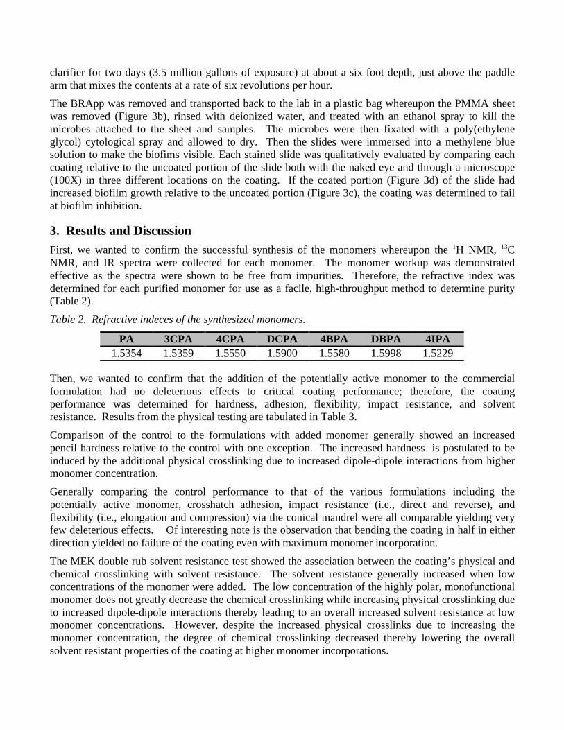
The extraction studies were performed on the control and on each of the coatings with twenty percent by weight incorporation of the potentially active monomer. Interestingly, after soaking the powdered coating in methanol for a week, none of the monomers were extracted from the coating (100 µg/mL detection limit) indicating that the monomers were near completely, covalently incorporated into the polymer matrix. Via AFM, the smoothness was determined for the control and each formulation at varying monomer concentrations. With the exception of PA, the smoothness as measured from the average peak-valley height and roughness generally increases as the concentration of the monomer increases due to the
increased cohesive and adhesive dipole-dipole interactions of the coating (Table 4). Comparing the peak-valley height of the cured coating formulations to the peak-valley requisite for surgical grade steel (Sy ≤ 1 µm), several of the cured coating formulations were well within the requisite value for surgical grade steel, providing evidence of smoothness capable of inhibiting many types of microbial growth by reducing the available surface area for attachment.1 Table 4. Surface roughness measured via AFM based on cantilever deflection values measured during the contact scanning mode where Sy is the average peak-valley height and Sa is the average roughness, both for the cured coating, where Sy values meeting surgical grade steel requisites are highlighted.
5 wt % 10 wt % 15 wt % 20 wt % Monomer Sy (µm) Sa (µm) Sy (µm) Sa (µm) Sy (µm) Sa (µm) Sy (µm) Sa (µm) PA 0.7185 0.1532 2.5917 0.1562 4.4568 0.1575 5.1233 0.1567 3CPA 2.265 0.1575 1.6857 0.1383 1.1517 0.107 0.8888 0.1077 DCPA 1.1553 0.1098 1.2905 0.1122 0.7758 0.1072 0.6703 0.105 4BPA 0.785 0.1532 1.3348 0.1552 0.819 0.1548 1.5117 0.1548 DBPA 1.4265 0.155 1.192 0.1545 0.7897 0.1537 0.7102 0.1528
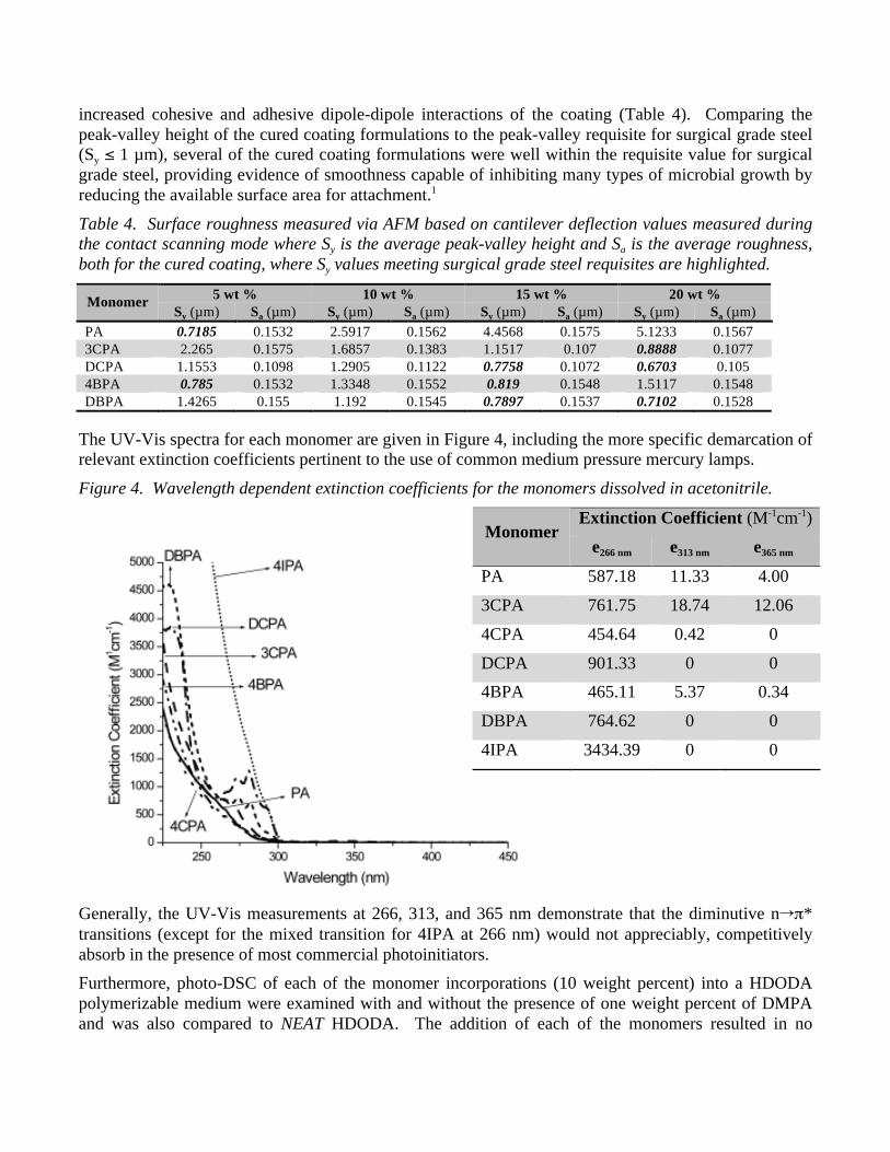
The UV-Vis spectra for each monomer are given in Figure 4, including the more specific demarcation of relevant extinction coefficients pertinent to the use of common medium pressure mercury lamps. Figure 4. Wavelength dependent extinction coefficients for the monomers dissolved in acetonitrile.
Extinction Coefficient (M-1cm-1) Monomer
e266 nm e313 nm e365 nm PA 587.18 11.33 4.00 3CPA 761.75 18.74 12.06 4CPA 454.64 0.42 0 DCPA 901.33 0 0 4BPA 465.11 5.37 0.34 DBPA 764.62 0 0 4IPA 3434.39 0 0
Generally, the UV-Vis measurements at 266, 313, and 365 nm demonstrate that the diminutive nπ* transitions (except for the mixed transition for 4IPA at 266 nm) would not appreciably, competitively absorb in the presence of most commercial photoinitiators. Furthermore, photo-DSC of each of the monomer incorporations (10 weight percent) into a HDODA polymerizable medium were examined with and without the presence of one weight percent of DMPA and was also compared to NEAT HDODA. The addition of each of the monomers resulted in no
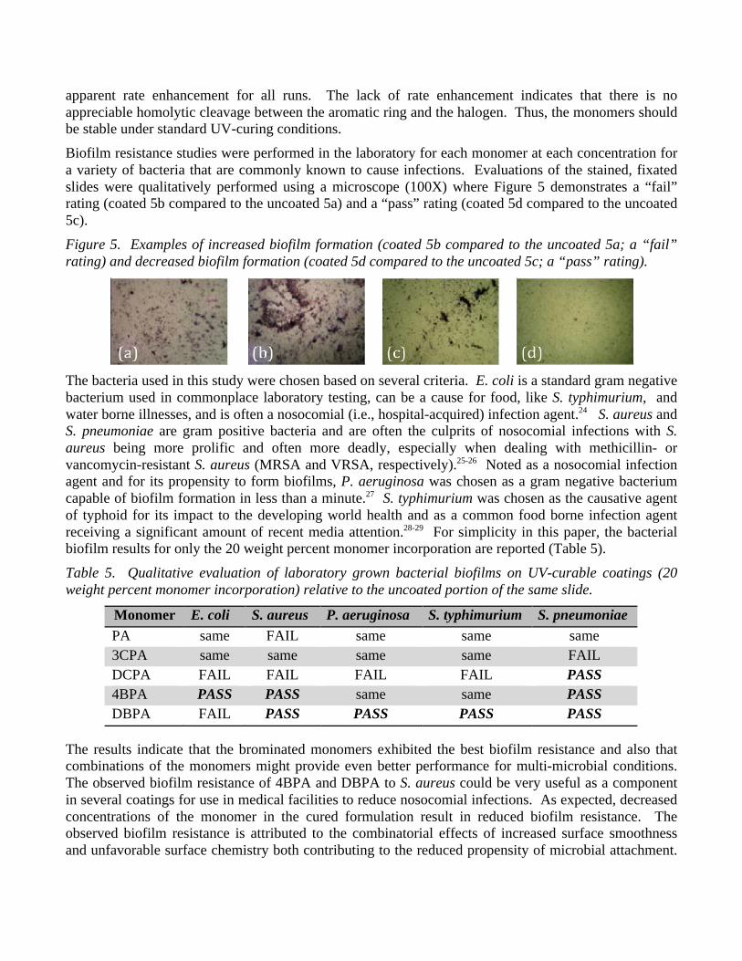
apparent rate enhancement for all runs. The lack of rate enhancement indicates that there is no appreciable homolytic cleavage between the aromatic ring and the halogen. Thus, the monomers should be stable under standard UV-curing conditions. Biofilm resistance studies were performed in the laboratory for each monomer at each concentration for a variety of bacteria that are commonly known to cause infections. Evaluations of the stained, fixated slides were qualitatively performed using a microscope (100X) where Figure 5 demonstrates a “fail” rating (coated 5b compared to the uncoated 5a) and a “pass” rating (coated 5d compared to the uncoated 5c). Figure 5. Examples of increased biofilm formation (coated 5b compared to the uncoated 5a; a “fail” rating) and decreased biofilm formation (coated 5d compared to the uncoated 5c; a “pass” rating).
The bacteria used in this study were chosen based on several criteria. E. coli is a standard gram negative bacterium used in commonplace laboratory testing, can be a cause for food, like S. typhimurium, and water borne illnesses, and is often a nosocomial (i.e., hospital-acquired) infection agent.24 S. aureus and S. pneumoniae are gram positive bacteria and are often the culprits of nosocomial infections with S. aureus being more prolific and often more deadly, especially when dealing with methicillin- or vancomycin-resistant S. aureus (MRSA and VRSA, respectively).25-26 Noted as a nosocomial infection agent and for its propensity to form biofilms, P. aeruginosa was chosen as a gram negative bacterium capable of biofilm formation in less than a minute.27 S. typhimurium was chosen as the causative agent of typhoid for its impact to the developing world health and as a common food borne infection agent receiving a significant amount of recent media attention.28-29 For simplicity in this paper, the bacterial biofilm results for only the 20 weight percent monomer incorporation are reported (Table 5). Table 5. Qualitative evaluation of laboratory grown bacterial biofilms on UV-curable coatings (20 weight percent monomer incorporation) relative to the uncoated portion of the same slide.
Monomer E. coli S. aureus P. aeruginosa S. typhimurium S. pneumoniae PA same FAIL same same same 3CPA same same same same FAIL DCPA FAIL FAIL FAIL FAIL PASS 4BPA PASS PASS same same PASS DBPA FAIL PASS PASS PASS PASS
The results indicate that the brominated monomers exhibited the best biofilm resistance and also that combinations of the monomers might provide even better performance for multi-microbial conditions. The observed biofilm resistance of 4BPA and DBPA to S. aureus could be very useful as a component in several coatings for use in medical facilities to reduce nosocomial infections. As expected, decreased concentrations of the monomer in the cured formulation result in reduced biofilm resistance. The observed biofilm resistance is attributed to the combinatorial effects of increased surface smoothness and unfavorable surface chemistry both contributing to the reduced propensity of microbial attachment.
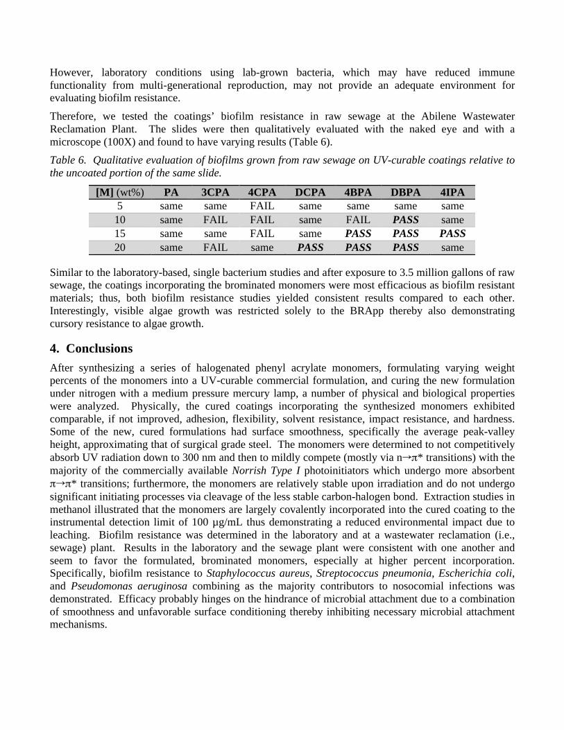
However, laboratory conditions using lab-grown bacteria, which may have reduced immune functionality from multi-generational reproduction, may not provide an adequate environment for evaluating biofilm resistance. Therefore, we tested the coatings’ biofilm resistance in raw sewage at the Abilene Wastewater Reclamation Plant. The slides were then qualitatively evaluated with the naked eye and with a microscope (100X) and found to have varying results (Table 6). Table 6. Qualitative evaluation of biofilms grown from raw sewage on UV-curable coatings relative to the uncoated portion of the same slide.
[M] (wt%) PA 3CPA 4CPA DCPA 4BPA DBPA 4IPA 5 same same FAIL same same same same 10 same FAIL FAIL same FAIL PASS same 15 same same FAIL same PASS PASS PASS 20 same FAIL same PASS PASS PASS same
Similar to the laboratory-based, single bacterium studies and after exposure to 3.5 million gallons of raw sewage, the coatings incorporating the brominated monomers were most efficacious as biofilm resistant materials; thus, both biofilm resistance studies yielded consistent results compared to each other. Interestingly, visible algae growth was restricted solely to the BRApp thereby also demonstrating cursory resistance to algae growth.
4. Conclusions After synthesizing a series of halogenated phenyl acrylate monomers, formulating varying weight percents of the monomers into a UV-curable commercial formulation, and curing the new formulation under nitrogen with a medium pressure mercury lamp, a number of physical and biological properties were analyzed. Physically, the cured coatings incorporating the synthesized monomers exhibited comparable, if not improved, adhesion, flexibility, solvent resistance, impact resistance, and hardness. Some of the new, cured formulations had surface smoothness, specifically the average peak-valley height, approximating that of surgical grade steel. The monomers were determined to not competitively absorb UV radiation down to 300 nm and then to mildly compete (mostly via nπ* transitions) with the majority of the commercially available Norrish Type I photoinitiators which undergo more absorbent ππ* transitions; furthermore, the monomers are relatively stable upon irradiation and do not undergo significant initiating processes via cleavage of the less stable carbon-halogen bond. Extraction studies in methanol illustrated that the monomers are largely covalently incorporated into the cured coating to the instrumental detection limit of 100 µg/mL thus demonstrating a reduced environmental impact due to leaching. Biofilm resistance was determined in the laboratory and at a wastewater reclamation (i.e., sewage) plant. Results in the laboratory and the sewage plant were consistent with one another and seem to favor the formulated, brominated monomers, especially at higher percent incorporation. Specifically, biofilm resistance to Staphylococcus aureus, Streptococcus pneumonia, Escherichia coli, and Pseudomonas aeruginosa combining as the majority contributors to nosocomial infections was demonstrated. Efficacy probably hinges on the hindrance of microbial attachment due to a combination of smoothness and unfavorable surface conditioning thereby inhibiting necessary microbial attachment mechanisms.

5. Acknowledgements The authors would like to thank the Albemarle Corporation for providing DMPA and Allied Photochemical for providing the standard formulation used. We would also like to gratefully acknowledge the financial support of The Welch Foundation (Grant R-0021) and the Abilene Christian University Office of Research and Sponsored Programs.
6. References 1. Skinner, D. "UV Curing in the Plastic Components Industry." Polymer, Paint and Coatings Journal. (September
2002), 19-23. 2. Grosset, A.; Su, W.A.. Ind. Eng. Prod. Res. Dev. (1985), 113-120. 3. Selli, E.; Bellbono, I.R. Radiation Curing Polymer Science and Technology. Vol. 3, J. P. Foussier and J. F. Rabek,
eds. Elsevier, London (1993). 4. Flemming, H. –C. Appl. Microbiol. and Biotechnol. 59(6), (2002), 629-640. 5. Kenawy, El-Refaie; Worley, S.D.; Broughton. R. Biomacromolecules. 8, (2007), 1359-1384. 6. O' Flaherty, S.; Ross, R.P.; Meanry, W.; Fitzgerald, G.F. Appl. and Environ. Microbiol. 1(4), (2004), 1836-1842. 7. Montanaro, L.; Campoccia, D.; Pirini, V.; Ravaioli, S.; Otto, M. J. Biomed. Mat. Res. Part A. (June 8, 2007), 1-7. 8. "Medical Devices." RadTech International. (2012). accessed February 23, 2012.
<http://www.radtech.org/index.php?option=com_content&view=article&id=112&Itemid=67>. 9. Cleaveland, P. "An Evolution in Coatings." Med. Design Technol. (2005), 18-22. 10. Douglas, J. W. "Acquisition and Technology of the Senate of Armed Forces." U. S. Navy. (March 12, 1998).
accessed February 23, 2012. <http://www.navy.mil/navydata/testimony/acquisition/doug0312.txt>. 11. Abbott, A,; Abel, P. D.; Arnold, D. W.; Milne, A. Sci. Total. Environ. (2000), 258, 5-19. 12. Cooney, J. J.; Tang, R. J. Methods Enzymol. (1999), 310, 637-645. 13. Brancato, M. S. OCEANS 1999 MTS/IEEE, Riding the Crest into the 21st Century. (1999), 2, 676. 14. Reise, K.; Gollasch, S.; Wolff, W. J. Helgolander Meeresnters. (1999), 52, 219-234. 15. Dreeszen, P. H. “Biofilm.” Edstrom Industries Inc., The key to understanding and controlling bacterial growth in
Automated Drinking Water Systems, 2nd Ed. (June 2003). 16. Tortora, G.; Funke, B.R.; Case, C.L. Microbiology: An Introduction. 9th Ed. Pearson Publishing Company, (2006). 17. Ignatova, M.; Voccia, S.; Gilbert, B.; Markova, N.; Cossement, D.; Gouttebaron, R.; Jerome, R.; Jerome, C.
Langmuir. (2006), 22, 255-262. 18. Razatos, A.; Ong, Y.L.; Boulay, F.; Elbert, D.L.; Hubbell, J.A. J. Amer. Chem. Soc. (2000), 9155-9158. 19. “Standard Test Method for Film Hardness by Pencil Test.” ASTM D 3363-05. (January 1, 2005). 20. “Standard Practice for Assessing the Solvent Resistance of Organic Coatings Using Solvent Rubs.” ASTM D 5402-
06. (August 1, 2006). 21. “Standard Test Methods for Measuring Adhesion by Tape Test.” ASTM D 3359-08. (February 8, 2008). 22. “Standard Test Method for Impact Flexibility of Organic Coatings.” ASTM D 6905-03. (May 10, 2003). 23. “Standard Test Methods for Mandrel Bend Test of Attached Organic Coatings.” ASTM D522-93a. (February 15,
2008). 24. Madappa, T.; Go, C. H. U. “Escherichia Coli Infections.” (November 15, 2011). accessed on: 26 July 2011.
<http://emedicine.medscape.com/article/217485-overview#showall>. 25. Muench, D. F.; Rajnik, M. “Pneumococcali Infections.” (November 3, 2010). accessed on: 26 July 2011.
<http://emedicine.medscape.com/article/225811-overview#showall>. 26. Tolan, Jr., R. W.; Baorto, E. P.; Baorto, D. “Staphylococcus Aureus Infection.” (January 10, 2012). accessed on:
February 23, 2012. <http://emedicine.medscape.com/article/971358-overview#showall>.
27. Qarah, S.; Cunha, B. A.; Dua, P.; Lessnau, K.-D.. “Pseudomonas aeruginosai Infections.” (January 11, 2012). accessed on: February 23, 2012. <http://emedicine.medscape.com/article/226748-overview#showall>.
28. “Typhoid Fever.” (October 5, 2010). accessed on: February 23, 2012. <http://www.cdc.gov/nczved/divisions/dfbmd/diseases/typhoid_fever/>.
29. Cavallaro, E.; Date, K.; Medus, C.; et al. N. Engl. J. Med. (2011). 365, 601-610.