missouri’s experience with a diverging diamond...
TRANSCRIPT

Missouri’s Experience with a
Diverging Diamond Interchange
Lessons LearnedMissouri Department of Transportation www.modot.org

Technical Report Documentation Page
1. Report No.: OR 10 - 021
2. Government Accession No.:
3. Recipient's Catalog No.:
4. Title and Subtitle: Missouri’s Experience with a Diverging Diamond Interchange - Lessons Learned
5. Report Date: May 2010
6. Performing Organization Code:
7. Author(s): Missouri Department of Transportation
8. Performing Organization Report No.:
9. Performing Organization Name and Address: Design and Traffic Divisions
Missouri Department of Transportation
10. Work Unit No.: 3H72
11. Contract or Grant No.: None
12. Sponsoring Agency Name and Address: Missouri Department of Transportation Organizational Results PO Box 270 Jefferson City MO 65102
13. Type of Report and Period Covered: Final – as of May 2010
14. Sponsoring Agency Code:
15. Supplementary Notes This best practices document was developed by a team consisting of Traffic, Design, and Missouri District 4, District 6 and District 8 personnel.
16. Abstract: The first DDI in the nation opened to traffic on June 21, 2009, in Springfield, Missouri. The interchange in Springfield where the Kansas Expressway (MO-13) passes over I-44 is a huge success. A diverging diamond interchange (DDI), sometimes referred to as a double crossover diamond (DCD), is a diamond interchange that more efficiently facilitates heavy left-turn movements. While the ramp configuration is similar to a traditional diamond interchange, traffic on the cross route moves to the left side of the roadway for the segment between signalized ramp intersections. By moving traffic to the left, left-turning vehicles can enter the limited access highway without the need for a left-turn signal phase at the signalized ramp intersections. Also, left-turning vehicles on the cross route do not conflict with opposing through traffic and may turn without stopping. This report was prepared based upon current knowledge and experience with building and operating the nation’s first Diverging Diamond Interchange (DDI). MoDOT’s Engineering Policy Guide (EPG) will be updated to reflect current practices as institutional knowledge and experience increases. 17. Key Words:
Diverging Diamond Interchange, DDI, double crossover diamond, DCD, Springfield, Missouri, Kansas Expressway, MO-13, I-44, Interstate 44, Missouri 13 Highway, First in the nation, innovative design, innovative solution, crossover route, left-turning vehicle
18. Distribution Statement No restrictions. This document is available to the public through National Technical Information Center, Springfield, Virginia 22161
19. Security Classification (of this report): Unclassified
20. Security Classification (of this page): Unclassified
21. No. of Pages: 142
22. Price:
Form DOT F 1700.7 (06/98)

Missouri’s Experience with a Diverging Diamond Interchange
The first DDI in the nation opened to traffic on June 21, 2009, in Springfield, Missouri, the birthplace of historic US Route 66. The interchange in Springfield where the Kansas Expressway (MO-13) passes over I-44 is a huge success. At peak hours of the day, southbound traffic on MO-13 would back up to one mile and, at times, up to two miles during major traffic generating events. Now, the same traffic moves through the interchange within a matter of minutes. The interchange has been the subject of multiple news and journal articles and was chosen as one of the best new engineering innovations of 2009 by Popular Science
magazine.
This report was prepared based upon current knowledge and experience with building and operating the nation’s first Diverging Diamond Interchange (DDI). MoDOT's Engineering Policy Guide (EPG) will be updated to reflect current practices as institutional knowledge and experience increases.
Table of Contents
Chapter 1 Introduction ............................................................................................................ 1
Chapter 2 Design Elements .................................................................................................... 4
Chapter 3 Construction Issues .............................................................................................. 21
Chapter 4 Operational Aspects ............................................................................................. 22
Chapter 5 Other Aspects to Consider ................................................................................. 25
Chapter 6 Public Involvement .............................................................................................. 26 Additional Resources................................................................................................................. 28 Appendices .................................................................................................................................... 30

Missouri’s Experience with a Diverging Diamond Interchange
Missouri Department of Transportation 1 DDI: Lessons Learned
Chapter 1 Introduction Discussion A diverging diamond interchange (DDI), sometimes referred to as a double crossover diamond (DCD), is a diamond interchange that more efficiently facilitates heavy left-turn movements. While the ramp configuration is similar to a traditional diamond interchange, traffic on the cross route moves to the left side of the roadway for the segment between signalized ramp intersections. By moving traffic to the left, left-turning vehicles can enter the limited access highway without the need for a left-turn signal phase at the signalized ramp intersections. Also, left-turning vehicles on the cross route do not conflict with opposing through traffic and may turn without stopping. Advantages
A DDI reduces total conflict points from the 30 points within a traditional diamond to only 18. Furthermore, the reduction mainly applies to the number of crossing points, the most crucial conflict type; a drop from 10 to two, as shown in Table 1. When compared to a single point urban interchange (SPUI), a DDI reduces the total conflict points from 24 to 18. In this case, the reduction is strictly a result of fewer crossing points. Figure 1.1 below shows a traditional diamond interchange on the left and a SPUI on the right while Figure 1.2 shows the layout of a DDI. The dots on the drawings show the location of the points of conflict.
Table 1 Conflict Points Type Diamond SPUI DDI
Diverging 10 8 8 Merging 10 8 8 Crossing 10 8 2
Total 30 24 18
Figure 1.1 Points of conflict on traditional interchanges

Missouri’s Experience with a Diverging Diamond Interchange
Missouri Department of Transportation 2 DDI: Lessons Learned
Figure 1.2 Conflict diagram for a DDI
In addition to reduced conflict points, the most notable advantage of the DDI over the other types of diamond interchanges is that substantially higher left-turn movements can be accommodated both onto and off the limited access highway. This increase in left-turn capacity can be accomplished without drastically increasing the required cross route width. The ability to accommodate a high number of left turns improves the efficiency and, thereby, the capacity of the interchange. The channelization necessary to move vehicles to the left side of the roadway can create a calming effect on overall traffic, which should reduce speed and create fewer and less severe crashes. In addition, wrong-way movements to and from the ramps are virtually eliminated. The reduced clearance distance on the ramps decreases exposure time within the intersection thus improving safety further. Another advantage is that the signal operation improves by using a two-phase signal that can use short cycle lengths. This can significantly reduce delays along the cross route and will increase the safety and capacity of the interchange by decreasing queuing on the cross route. The application of a DDI may reduce project costs by allowing the use of existing structures and right of way or, at least, requiring the narrowest or shortest bridge and right of way template possible. This is mainly due to the reduction of required left-turn lanes. In fact, under appropriate traffic conditions, designated left-turns can be eliminated in one or both directions on the cross route. An interesting benefit of the layout of a DDI is that it provides an easy U-turn for a driver on the limited access highway to return to a missed exit. This added benefit can also aid with incident management for interchanges downstream or upstream and detours for nearby construction.

Missouri’s Experience with a Diverging Diamond Interchange
Missouri Department of Transportation 3 DDI: Lessons Learned
Disadvantages While the advantages of the DDI make it an attractive solution for a variety of traffic conditions, it is not applicable everywhere. As with any solution, there are disadvantages to consider. The first of which is when current or projected through volumes are high. The drivers inconvenienced the most by the installation of a DDI are those going through on the cross route because they must crossover to the left side of the road and then back again to reach their destination. Through movements must be controlled and cannot be free-flow. If current or projected through traffic volumes are high, other interchange configurations should be considered at the conceptual stage. Since motorists are driving on the left side of the road, the interchange may initially be confusing to some and may not readily be embraced by the public. However, an aggressive public information campaign along with appropriate marketing and education can minimize this issue. If fact, when public relations are conducted effectively, the DDI can sell itself. Another disadvantage is that off-ramp traffic may not re-enter the limited access highway. The configuration of the interchange forces off-ramp traffic to either turn left or right and prohibits going straight through the ramp intersection. This can adversely affect confused motorists who take the wrong exit, oversized loads and incident management. When pedestrian facilities are present, the left or right turn to and from the ramps may require signalization and negatively influence the interchange’s operation. The negative impact may be minimized depending upon geometrics and other design choices. Some at-grade pedestrian crossings can be located where oncoming traffic approaches from an unfamiliar direction. Since pedestrians are typically conditioned to look “left–right-left” before crossing the street, there is potential for pedestrian confusion at these locations. Although signalization may improve the situation for pedestrians, the issue will unlikely be eliminated. Crossing over the traffic to the other side of the road usually requires additional space along the cross route. Additionally, signalized intersections close to a DDI can complicate its operation due to signal timing issues. The location of nearby access points and their control must be taken into account when considering the use of a DDI as a solution. DDIs may not work well when adjacent intersections on the cross route are closely located and experience heavy traffic themselves.

Missouri’s Experience with a Diverging Diamond Interchange
Missouri Department of Transportation 4 DDI: Lessons Learned
Chapter 2 Design Elements
Conceptual Issues
Modeling/Simulation An operational analysis (traffic study) should be conducted whenever a DDI is considered. Operational measures such as Level of Service (LOS), delay and capacity can be used to compare the operational characteristics of a DDI with other types of interchanges, such as traditional diamonds or SPUIs. The operational analysis can also be used to determine the number of lanes and the configuration needed for the DDI to operate acceptably. Generally, micro-simulation modeling, such as VISSIM, is the preferred method for analyzing a DDI. In some situations, such as at isolated interchange locations and at low-volume locations, traditional Highway Capacity Manual (HCM) methods can produce reasonable results. Any nearby intersections, less than half a mile from the interchange, should be included in the model. In addition to providing operational measures, micro-simulation models can be used to create animations. These animations are commonly used to help the public understand the DDI concept and the benefits of using a DDI at a particular location. Spacing of adjacent intersections As with any interchange type, it is desirable to follow the minimum intersection spacing shown in EPG Article 940.3. However, special consideration must be given in evaluating a DDI when the nearest full access intersection is significantly less than the minimum distance shown in the EPG. The DDI operates essentially as a two-phase signal with only one direction of travel on the cross route allowed through the interchange at a time. When there is a signalized intersection too close to the DDI, it is generally not possible to coordinate both directions of travel along the cross route with the adjacent signal resulting in one direction of travel queuing in the small space between the intersections. When considering a DDI with a signalized intersection close to the interchange, other interchange types should also be considered. Traffic projections require additional attention when evaluating the use of a DDI in a closely spaced signal system. When this is the case, a sensitivity analysis should be performed. A sensitivity analysis evaluates how changes in the traffic projections affect the results of the operational analysis (LOS or capacity). The sensitivity analysis will show if the proposed improvements only work under a limited number of traffic conditions or if the proposed improvements are flexible enough to satisfy a variety of future traffic conditions. At this time, it does not appear that closely spaced right-in, right-out access or left-in accesses pose a greater challenge for DDIs compared to other interchange types. When evaluating non-signalized access points, additional care should be given so the access does not interfere with the operations of the right turns either onto or off the ramps.
Design Issues
Design Speed
Besides the normal controlling factors of design speed, e.g. vertical sight distance, the major controlling element of a DDI design speed is the horizontal geometrics of the two crossovers. These two crossovers can act as a traffic-calming device. Some other factors that can influence the design speed of a DDI are traffic volumes, percentage of trucks, right-of-way and existing conditions.

Missouri’s Experience with a Diverging Diamond Interchange
Missouri Department of Transportation 5 DDI: Lessons Learned
Without crossovers, the design speed of cross route would be higher in most cases and design elements such as sight distance should be based on that higher speed.
MoDOT’s experience is that, for through traffic, it is desirable for regular passenger vehicles to be able to proceed through a DDI at 20-30 mph without encroaching upon an adjacent lane. MoDOT’s past and current designs are allowing speeds of about 25 mph. It is highly recommended that WB-67s, MoDOT’s designated design vehicle, be able to proceed through a DDI at 20 mph and make all turning movements to and from ramps at 15 mph.
Horizontal Crossover Geometrics
The physically defining characteristic of a DDI is that opposing traffic crosses and travels between the ramps of the interchange on the left side of the road and then crosses back. This is achieved by two crossovers at signalized intersections. Driving on the left side of the road violates a well-ingrained driver expectation. The crossovers are essentially non-traditional intersections of two one-way roads where only through movements occur. The greatest potential for driver confusion is at these locations within the interchange. The layout and design of the crossovers should strive to minimize potential driver confusion and encourage the correct driver movements. General Considerations
Based on appearance alone, it is possible to view the geometric layout of the crossovers as simply a series of reverse curves, but a well-designed crossover requires more consideration. The design of the horizontal geometrics for each crossover is site specific. For practical design application, the center of each crossover can be slightly skewed from the cross route centerline and/or offset, as shown below in Figure 2.1.
Figure 2.1 Center of the crossover offset and skewed from centerline of cross route Placement of the two crossovers is largely dependent upon the spacing and location of the ramps. The space needed for vehicular storage between the crossovers must also be considered. When there is room, there is a fair degree of flexibility in the placement of the crossovers. If more length is

Missouri’s Experience with a Diverging Diamond Interchange
Missouri Department of Transportation 6 DDI: Lessons Learned
needed than the distance between ramp termini provides, the crossovers may be located further apart, as shown in Figure 2.2. As a result, the ramp entrances and exits will need to be configured to merge or diverge with the cross route by either extending or shortening them.
Figure 2.2 The crossover placed approximately 150’ away from ramp baseline termini The horizontal crossover geometrics consist of three main interacting elements: 1) crossing angle; 2) tangent length approaching and following the crossover; and 3) curve radii approaching and following the crossover. Crossing Angle
The crossing angle is the acute angle between lanes of opposing traffic within the crossover, as shown in Figure 2.3.
Figure 2.3 Crossing Angle

Missouri’s Experience with a Diverging Diamond Interchange
Missouri Department of Transportation 7 DDI: Lessons Learned
Several factors are important when choosing a crossing angle. The first is minimizing the likelihood of a driver making a wrong movement into opposing traffic. The greater the crossing angle, the more the crossover will appear like a “normal” intersection of two different cross routes and decrease the chance that a driver will make a wrong movement. Greater crossing angles also minimize the distance across the intersection and, thus, decrease the exposure a vehicle has to opposing traffic, but do result in larger footprints. Greater crossing angles can also increase the potential for driver discomfort that may aid traffic calming. However, caution should be exercised concerning driver discomfort, especially for through traffic. Safety for vehicles with higher centers of gravity, such as trucks, needs consideration. Larger crossing angles in combination with sharper reverse curves can increase potential for overturning and excessive driver discomfort due to centripetal forces acting on the driver shifting back and forth depending on speed. Another compounding factor to driver discomfort concerning crossing angle is when the roadway between and/or approaching the crossover is constrained. Conversely, lesser crossing angles will increase the potential for wrong way movements by confused drivers, increase crossing distance and, thus, exposure to opposing traffic. In addition, lesser crossing angles will likely cause less driver discomfort and fit into a smaller footprint. Missouri has used crossing angles ranging from 40-50° in its designs. A recommended approach is to use the largest crossing angle possible while balancing each of the horizontal geometric crossover aspects. Tangent Length
The majority of MoDOT’s past and current DDI designs have used some tangent length between the curves of the crossover. For the most part, though, the tangent length used has not been extended beyond the intersection. However, using design principles borrowed from roundabouts, extending a tangent length both before and after the crossover can decrease potential driver confusion and improve the overall safety of the interchange.
The most valuable aspect of adding tangent length before and after a crossover is the propensity to align vehicles with their correct receiving lane as they approach the crossover. Crossover movements in the middle of reverse curves can lead to vehicle path overlap. This is especially true for vehicles at rest behind the stop bar waiting for a green light. Without a short tangent length, vehicles staggered behind stop bars can line up with the adjacent lane rather than their own, as demonstrated in Figure 2.4. Short tangent lengths will aid in guiding the vehicles through the intersection.
Figure 2.4 Windshield view demonstrating vehicle path overlap in a typical DDI design

Missouri’s Experience with a Diverging Diamond Interchange
Missouri Department of Transportation 8 DDI: Lessons Learned
Additionally, crossover movements that occur in the middle of reverse curves force drivers to make directional corrections within the crossover that can lead to encroachment upon an adjacent lane. Crossover movements on tangents reduce, if not eliminate, directional corrections within the crossover. A short tangent length extending beyond the crossover can also aid in locating and aiming the signal head directly over the correct lane. Visibility of the signal indication for drivers approaching the intersection should be considered as well.
By extending a short tangent length before and after the crossover, the result may be the need for either a lesser crossing angle or smaller curve radii at the crossovers. It is important to remember that a well-designed crossover is a balancing act of these three elements and the effect of more tangent length can potentially have an undesirable impact on these other two elements. Appropriate consideration should be given when extending the tangent length especially when space is constrained.
When tangent length beyond the intersection is used, a length of 15-20 feet along the inner edge of pavement is recommended before the crossover. This distance should be provided measuring from behind the stop bar when possible, but may be provided from the crossover itself when space is limited. Since cars do not experience stopping after the crossover, a shorter length of about 10-15 feet along the inner edge of pavement is encouraged. Figure 2.5 shows the recommended minimum lengths. If crossing angles less than what Missouri has designed are used, it may be helpful to use longer than the recommended lengths.
Figure 2.5 Recommended tangent length before and after crossover Curve Radii
The curves approaching and following the crossover should allow the design vehicle to navigate the interchange at the design speed as well as accommodate the turning movements to and from the ramps. Each curve should transition to and from the tangents of the crossover as shown in Figure 2.6. While many designs utilize similar curve radii for each side of the crossover, an optimized design can require different curve radii for each side, before and after the crossover creating an asymmetrical design. Some of the factors that can influence these curve radii are design speed, crossing angle, tangent length, right-of-way, median width and vehicle storage for turning lanes of adjacent intersections.

Missouri’s Experience with a Diverging Diamond Interchange
Missouri Department of Transportation 9 DDI: Lessons Learned
One approach to design these curves is to start with a 200-foot radius along the inner edge of pavement both before and after the crossover and then adjust the radii until optimum design is achieved. Curve radii used in MoDOT DDI designs range generally from 150-300 feet.
Figure 2.6 Curve radii approaching and following the crossover Lane Width
Lane width on the cross route of a DDI is somewhat site and project specific. What is challenging regarding lane widths of DDIs is the crossover. In most cases, the lane width of the crossover will need to be wider than the standard cross route lane width. The crossover lane width is a function of the layout and horizontal geometrics in conjunction with modeling the off tracking of a WB-67. Most past and current MoDOT DDIs widen out the lane width for the crossover to 15 feet. A recommended approach is to begin the design using lane widths of 15 feet and reduce them based on the off-tracking modeling until optimum lane width is achieved. Standard lane width may be achievable when the horizontal geometrics allow it. Such might be the case if the cross route has a wide median.
Whatever lane width is used, all passenger vehicles should have the ability to stay in their own lane through the crossover. If truck traffic is light, it is at the designer’s discretion whether to allow off-tracking trucks to encroach upon an adjacent lane. When heavy truck traffic is present, wider lane widths are desirable and consideration must be given to the potential for two trucks to navigate side-by-side through the interchange. What can also have a significant impact upon lane width between the crossovers is whether there is a single- or dual-left turn into those lanes. It is worth noting that truck drivers are instructed to use the right-most lanes when there are multiple left-turn lanes.
All approach lanes on the cross route should be tapered to the crossover lane-width before entering the curve approaching the crossover and maintained through the curve after the crossover. Between the crossovers, lane widths may need to be tapered down if existing conditions constrain the roadway. Existing structures can limit lane-width between crossovers. Right-of-way can affect lane-width approaching a crossover. Pedestrian and bicycle accommodation can influence lane-widths before, after and between the crossovers. The ramp spacing and distance between the crossovers are additional considerations. The lane-width between the crossovers should meet standard lane-width where possible but not exceed the lane-width of the crossover.
Missouri’s Experience with a Diverging Diamond Interchange
Missouri Department of Transportation 10 DDI: Lessons Learned
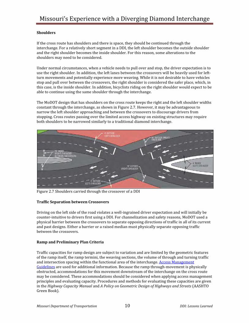
Shoulders
If the cross route has shoulders and there is space, they should be continued through the interchange. For a relatively short segment in a DDI, the left shoulder becomes the outside shoulder and the right shoulder becomes the inside shoulder. For this reason, some alterations to the shoulders may need to be considered.
Under normal circumstances, when a vehicle needs to pull over and stop, the driver expectation is to use the right shoulder. In addition, the left lanes between the crossovers will be heavily used for left- turn movements and potentially experience more weaving. While it is not desirable to have vehicles stop and pull over between the crossovers, the right shoulder is considered the safer place, which, in this case, is the inside shoulder. In addition, bicyclists riding on the right shoulder would expect to be able to continue using the same shoulder through the interchange.
The MoDOT design that has shoulders on the cross route keeps the right and the left shoulder widths constant through the interchange, as shown in Figure 2.7. However, it may be advantageous to narrow the left shoulder approaching and between the crossovers to discourage drivers from stopping. Cross routes passing over the limited access highway on existing structures may require both shoulders to be narrowed similarly to a traditional diamond interchange.
Figure 2.7 Shoulders carried through the crossover of a DDI
Traffic Separation between Crossovers
Driving on the left side of the road violates a well-ingrained driver expectation and will initially be counter-intuitive to drivers first using a DDI. For channelization and safety reasons, MoDOT used a physical barrier between the crossovers to separate opposing directions of traffic in all of its current and past designs. Either a barrier or a raised median must physically separate opposing traffic between the crossovers.
Ramp and Preliminary Plan Criteria
Traffic capacities for ramp design are subject to variation and are limited by the geometric features of the ramp itself, the ramp termini, the weaving sections, the volume of through and turning traffic and intersection spacing within the functional area of the interchange. Access Management Guidelines are used for additional information. Because the ramp through-movement is physically obstructed, accommodations for this movement downstream of the interchange on the cross route may be considered. These accommodations should be considered when applying access management principles and evaluating capacity. Procedures and methods for evaluating these capacities are given in the Highway Capacity Manual and A Policy on Geometric Design of Highways and Streets (AASHTO Green Book).
Missouri’s Experience with a Diverging Diamond Interchange
Missouri Department of Transportation 11 DDI: Lessons Learned
Ramp design for a DDI should take into consideration the need of separate lanes for left- and right-turning traffic especially when either of these movements is signalized. While traditional ramp designs allow for shared lane usage, exit ramp design for a DDI should provide separate left- and right-turn lanes prior to the ramp terminal. This is because the phasing for the signalized left turn and right turn will not occur simultaneously. The storage lengths of these lanes are dependent upon projected volumes and potential queuing. Typically, ramp base lines are always equated to the survey centerline and other ramp base line intersection points or the cross route centerline intersection point. The equations include offsets and intersection angles. For ease of identification, interchange ramps are numbered. Ramp details can be found on Standard Plan 203.40. The district approves the geometric layout of a DDI from the schematic drawing shown on the preliminary plan.
At this preliminary plan stage, interchange geometric sheets are submitted to the Design Division for review and comments. Plans are also submitted for all full oversight projects for Federal Highway Administration (FHWA) approval.
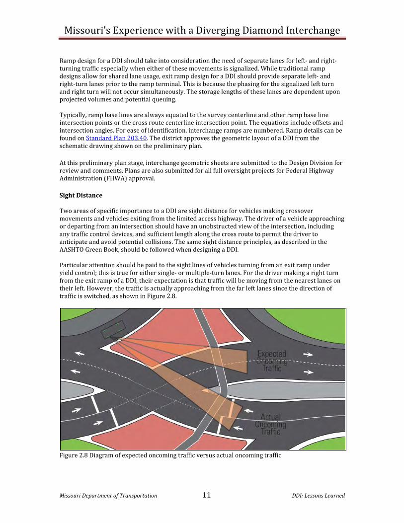
Sight Distance Two areas of specific importance to a DDI are sight distance for vehicles making crossover movements and vehicles exiting from the limited access highway. The driver of a vehicle approaching or departing from an intersection should have an unobstructed view of the intersection, including any traffic control devices, and sufficient length along the cross route to permit the driver to anticipate and avoid potential collisions. The same sight distance principles, as described in the AASHTO Green Book, should be followed when designing a DDI. Particular attention should be paid to the sight lines of vehicles turning from an exit ramp under yield control; this is true for either single- or multiple-turn lanes. For the driver making a right turn from the exit ramp of a DDI, their expectation is that traffic will be moving from the nearest lanes on their left. However, the traffic is actually approaching from the far left lanes since the direction of traffic is switched, as shown in Figure 2.8.
Figure 2.8 Diagram of expected oncoming traffic versus actual oncoming traffic

Missouri’s Experience with a Diverging Diamond Interchange
Missouri Department of Transportation 12 DDI: Lessons Learned
If there is room, a possible way to minimize this issue is by moving the right turn further from the crossover to increase the amount of sight distance available to these right-turners as well as give them more time to realize where oncoming traffic is coming from. Another consideration is to channelize the right turn coming off the ramp more so when drivers turn to view the oncoming traffic, it more likely falls in their natural line of sight. If a median barrier is installed between the opposing directions of traffic to allow for a sidewalk or physical separation of vehicles, care should be taken to provide adequate sight distance. If the concrete barrier wall interferes with sight distance, it should be constructed using a shorter wall that tapers from 24 inches near the ends to the full height of 42 inches when sight distance is no longer obstructed as depicted by the red line on the barrier in Figure 2.9.
Figure 2.9 The red line shows how the barrier wall could be altered to provide better sight distance
Acceleration and Deceleration Lanes (Parallel Type)
Minimum speed-change lengths are provided in Exhibits 10-70 and 10-73 of the AASHTO Green Book. Lengths shown in these tables are for grades of two percent or less on the speed-change lane. Exhibit 10-71 of the AASHTO Green Book provides adjustment to these lengths for grades over two percent. Speed-change lanes are provided at all ramp entrances and exits where the numbers of through traffic lanes on each side of the ramp terminal are equal. A shoulder at least six feet wide is provided for auxiliary lanes along the through-traffic lanes. Auxiliary lane width is the same as the width provided for the through-traffic lanes. In rural areas, the ramp nose will be visible to approaching traffic for a distance equal to at least 1.25 times the stopping sight distance on the limited access highway. Where interchanges are closely spaced, less than one mile, the auxiliary lane for acceleration will be extended to the exit of the next interchange. An entrance lane followed by a lane exiting forms a traffic-weaving section that requires additional-length weaving capacity. The capacity of the auxiliary lane connecting the on-ramp with the off-ramp will be determined using the Highway Capacity Manual or an appropriate traffic-modeling program (i.e. VISSIM). The weaving section will have a length and number of lanes based on the appropriate level of service outlined in the Facility Selection article. Where a two-lane entrance ramp or a two-lane exit ramp is needed for capacity or lane balance, the effective length of auxiliary lane will be determined as illustrated in Exhibits 10-76 and 10-77 of the AASHTO Green Book.

Missouri’s Experience with a Diverging Diamond Interchange
Missouri Department of Transportation 13 DDI: Lessons Learned
Clear Zones
Clear zones are provided on all ramps and the cross route where feasible. Specific guidance concerning clear zones is found in the Clear Zone article. Turning Movements Unique to DDIs The DDI presents two unique turning movements not seen at any other interchange configuration: left turns onto and from ramps that are unopposed by other vehicular traffic. Under traditional diamond control, these turning movements are signalized with a left-turn movement opposed by oncoming traffic. The DDI’s advantage is to make the movement from the cross route to the limited access highway more efficient. No restrictions should be placed on the left turn onto the limited access highway unless pedestrian issues dictate otherwise. Traffic Control Options for Turning Movements The defining concept of the DDI is the ability to remove the conflicting left turn for traffic entering the limited access highway. Placing any traffic control on this movement is discouraged. The DDI off-ramp left turn has one conflict point, which is similar to the off-ramp right turn. Therefore, the traffic control options are identical to the traditional off-ramp right turn; stop, yield and signal. Stop signs should not be used. Yield control is more practical with a one-lane left turn with low to moderate volumes but may be used on a dual left turn as a secondary option to signal control. The off-ramp right turn options, benefits and drawbacks are nearly identical to the off-ramp left turn. Yield control is more practical with a one-lane right turn with low to moderate volumes but may be used on a dual right turn as a secondary option to signal control. Stop control should only be used as an option when yield control is not practical. The cross route right turn is identical to any channelized right turn at a traditional interchange. Traffic control options are stop, yield or none. When the cross route right-turn is a single lane and has moderate to high volumes, no traffic control may be necessary. However, adequate geometry and auxiliary lane length must be provided. Unless all lanes enter the limited access highway, the right lane should merge into the left lane. Yield control is more practical with a single right turn with low to moderate volumes but may be used on a dual right turn as a secondary option to signal control. Stop control should only to be used as a last resort when yield control is not practical. Signalization may be appropriate when high volumes of pedestrians are present. Signals Placement and visibility of signal indications is of utmost importance in order to ensure drivers understand how to navigate the interchange. Many of the same philosophies for signal design of other intersections also apply to the DDI. Signal heads placed over each of the receiving lanes provide positive guidance through the intersection and should be aimed appropriately at the stop bar for each lane. Placement of the mast arms for both through movements is critical to ensure they do not block the view of the signal heads for either approach since traffic approaches the intersection from the same side of the cross route.

Missouri’s Experience with a Diverging Diamond Interchange
Missouri Department of Transportation 14 DDI: Lessons Learned
The addition of nearside signals at the crossover allows vehicles further back in the queue to see a signal indication as they approach the intersection and may help in keeping the queue moving and prevent rear-end crashes. If placing nearside signal heads at the intersection, be sure to consider their location. Placing the nearside signal too close to the divergence of the free left turn or the free right onto the ramp can lead to drivers making these movements believe they must stop and wait for a green indication. If this condition occurs, it can adversely affect the operation of the signal, especially if these movements have a shared lane. An advantage of the DDI is the potential elimination of signal phases for movements such as the off-ramp left-turn. However, there may be times when signalizing this movement is beneficial. Drivers may not be looking for approaching traffic since it comes from an unfamiliar direction. By signalizing this movement, conflicts can be reduced or eliminated if left turns on red are restricted. Under moderate to heavy demand, the green indication can be provided during times when no oncoming traffic is present and help eliminate the stop and start condition yield control tends to create. Other considerations may be the number of lanes, two or more, making this maneuver. Signalization of the left turn, especially if the left turn on red is eliminated, can increase the queue length for this movement and may require more storage on the ramp to accommodate the restrictions placed on this movement. When signalizing the off-ramp left-turn, the distance between the crossover intersection and the off-ramp left-turn should be minimized. The longer the distance for the through movement to clear the intersection, the longer the duration of the yellow and all-red intervals. Increases in clearance intervals reduce the effective green time of the signal and the efficiency of the signal. If left turns on red are allowed, it may be desirable to restrict this turn to the green interval to eliminate possible driver confusion as to the location of oncoming traffic in this unique interchange. A NO TURN ON RED (R10-11 series) sign may be posted to prohibit this movement. Pedestrian movements across a free right are generally not signalized and therefore do not include any pedestrian signals. However, pedestrian movements across conflicting movements are signalized and run concurrently with the non-conflicting vehicle phase. The number of signalized pedestrian movements should be minimized when possible and located where the shortest distance to cross occurs. By doing so, pedestrian crossing times are reduced and do not become the controlling factor in the signal operation. Pedestrians crossing along the outside of the interchange may create a longer distance for a pedestrian to walk, which creates longer pedestrian intervals and could become the control for the signal timing. Pedestrian facilities located along the outside of the interchange may also cause pedestrians to make more conflicting movements, walk a longer distance, and cross at an unsignalized left-turn. Typically, pedestrians cross with vehicles traveling in the same direction and any left-turning traffic yields to those pedestrians. However, in the DDI, most pedestrians are not accustomed to crossing at the unsignalized left-turn of a DDI. Additionally, most drivers will not expect a pedestrian conflict during this movement. This movement could be considered a “conflicting movement” and could cause the left-turn entrance ramp to become signalized. The defining concept of a DDI is the advantage of the free left, but by signalizing it for pedestrians, the efficiency of the interchange may be compromised. Traditional channelized right turns from an off-ramp are not usually signalized, so the use of signals on a single-lane, off-ramp right turn at first may not be considered. However, several conditions unique to the DDI could prove signalization as the best option regardless of the number of lanes and volumes. Again, since the direction of travel of oncoming traffic may be unfamiliar, drivers making the right turn from the ramp may fail to yield to the oncoming traffic unintentionally. By signalizing this movement, the potential conflict can be reduced or eliminated if right turns on red are restricted. Again, under moderate to heavy demand, the green indication can be provided during times when no

Missouri’s Experience with a Diverging Diamond Interchange
Missouri Department of Transportation 15 DDI: Lessons Learned
oncoming traffic is present and help eliminate the stop and start condition yield control tends to create. Other considerations may be the number of lanes, two or more, making this maneuver. However, signalization of the right turn, especially if the right on red is eliminated, can increase the queue length for this movement and may require more storage on the ramp to accommodate the restrictions placed on this movement. A decision to signalize could also be based on downstream conditions such as nearby entrances, weaving sections or turn-lane access. Since signal phases are reduced, one controller can be used to accommodate both signalized intersections. The traditional phase assignments, however, may be modified. Typically, for an eight-phase traditional intersection, phases 2 and 6 are through movements for the major route and phases 4 and 8 for the side street. For the DDI, phases 2 and 6 are the through movements for the same direction of travel at each of the intersections (i.e. northbound) and phases 4 and 8 are the through movements for the other direction of travel at each of the intersections (i.e. southbound) as shown in Figure 2.10.
8 6
4 2
Figure 2.10 Phase assignments for through movements of a DDI Pavement Marking Although a DDI may operate in an unusual manner, the pavement marking used is similar to other interchanges. However, MoDOT’s practice is to continue the yellow stripe on the left side of the vehicle and the white on the right between the crossovers to make the driver more comfortable when they crossover to the left side of the road. MoDOT essentially chooses to view the roadway between the crossovers as two separate one-way roads. Stop bars, yield bars and arrow lane markings are all standard applications. Dotted lane-line extensions are typically used to help guide motorists through the crossovers. Signing
For regulatory, warning and object markers, standard highway signing practices apply. In order to assist the driver to make a correct crossover movement, Missouri used a mirrored KEEP RIGHT regulatory sign to provide an additional reminder to KEEP LEFT. Due to driver unfamiliarity and crossovers dictating slower speeds, FHWA approval has been requested for an
advanced warning sign supplemented with an advisory speed plaque on the cross routes, such as the sign shown to the right. Guide signing presents the most challenges due to the absence of clear guidelines. Guide signing of a DDI should not be an after-thought. Primary and secondary guide signs should be applied properly and not condensed

Missouri’s Experience with a Diverging Diamond Interchange
Missouri Department of Transportation 16 DDI: Lessons Learned
or combined together. Appropriate driver information must be conveyed in order to ensure proper function and operation of any facility. The two major factors of guide-sign design are driver information and size and support structure. Providing a cardinal direction and a destination is typical for a primary guide sign. Primary guide signs typically have larger legends and route shields and display more information to the driver. This allows the sign to be visible from a greater distance and allows the driver more time to make decisions. Secondary guide signs are a supplement to the primary guide signs and confirm that the driver has made the correct lane decision by providing the route information. As with any other complex intersection, guide signs should be mounted overhead. This places the signs in a location that increases visibility, providing drivers with the maximum amount of time to make the correct lane choice. An overhead guide sign placed directly over the appropriate lane for specific destinations clearly indicates to the driver which lane to select. The destination information is very important because many drivers more readily look for a destination name rather than knowing their cardinal directions. Proper sizing of both the overhead signs and their support structures in the design phase can minimize costs of going back and correcting guide-signing issues after construction.
Pedestrians
All interchanges with their ramps and structures can be a challenge for designers to provide safe crossings for pedestrians. The complex geometrics of a DDI require that special consideration is given to those who may be traveling on foot or in a wheelchair. Anytime sidewalks approach the interchange they should continue through. If sidewalks are not present on the approaches, consideration should be given to the future development of the area. It may be more efficient to include sidewalks with the current construction versus a retrofit. Pedestrian behavior can be unpredictable. At times, they choose to cross where and when they desire. Drivers and pedestrians may choose to violate a signal if it appears unnecessary or to be too time consuming to comply. They may also unintentionally violate a signal. Placement of the sidewalks greatly affects the overall design and operation of a DDI. Consideration of pedestrian accommodations should occur at the conceptual design stage. Modeling of the design with pedestrians is highly recommended. There are two basic ways to accommodate pedestrians at a DDI. They can be placed in the middle of the cross route between the crossovers or kept on the outside perimeter. This decision can influence the number of signals and the capacity of the interchange. Pedestrians may encounter a situation in which traffic approaches from the opposite direction than is expected. People are accustomed to look “left–right-left” before crossing the street; therefore, this condition may need special consideration. Signalization may help the issue. However, it does not necessarily prevent pedestrians from making mistakes and may adversely affect traffic capacity. Signs or pavement markings instructing a pedestrian to look right or left may be helpful to alert pedestrians of oncoming traffic from an unexpected direction.

Missouri’s Experience with a Diverging Diamond Interchange
Missouri Department of Transportation 17 DDI: Lessons Learned
An option for when there is heavy pedestrian traffic when using this design is to install a blank out “No Turn on Red” sign for vehicles. Use of this sign will require the pedestrian “Walk” display to be activated only by pedestrian push button and not as a default with the adjacent through vehicle phase. Design of the pedestrian facilities should be in accordance with EPG Article 642. The width of the sidewalk is a minimum of five feet if there is at least a two-foot separation from the curb and a minimum of six feet wide if located adjacent to the curb. If bicycle traffic is anticipated to share the sidewalk, a minimum width of eight feet is required. Wider sidewalks than eight feet may be appropriate depending on the expected volumes of pedestrians and cyclists. All sidewalks must be compliant with the Americans with Disabilities Act Accessibility Guidelines (ADAAG) that can be found at www.access-board.gov/adaag/html/adaag.htm, or the Public Right of Way Accessibility Guidelines (PROWAG) that can be found at www.access-board.gov/prowac/. Also, pedestrian signal components must comply with the Manual on Uniform Traffic Control Devices (MUTCD) that can be found at www.mutcd.fhwa.dot.gov/.
Although standard curb ramps are an acceptable way to access a sidewalk on a channelizing island, it is strongly recommended at-grade cut throughs be used to provide positive guidance across sizable islands and the path through the island be as short and straight as possible so visually impaired persons do not become confused about the direction they are traveling. Two configurations have been designed for DDIs built in Missouri. The first, somewhat unconventional but very effective design, guides a pedestrian from the outside of the cross route to the ramp-channelizing island and then into the middle of the cross route between the crossovers as shown below in Figure 2.11.
Figure 2.11 Example of sidewalks in the middle of the cross route between the crossovers
There are several advantages to this configuration: • The two-phased signal provides pedestrians
a walk signal from the outside to the inside median sidewalk when conflicting traffic is stopped at signals.
• The number of times a pedestrian must cross the roadway unprotected is reduced and decreases the exposure to free flowing turning movements.
• Only one sidewalk is needed, which may result in less bridge area or roadway width.
• A pedestrian can cross to the other side of the cross route at the crossovers.

Missouri’s Experience with a Diverging Diamond Interchange
Missouri Department of Transportation 18 DDI: Lessons Learned
The disadvantages to this design: • When the limited access highway is above the cross route, the placement of the structural
obstacles may complicate the design. • If the pedestrian crossing is narrow, pedestrians may feel uncomfortable with traffic passing
on both sides.
Barrier separation from traffic should be used when pedestrians are placed down the center of the cross route. If bicycles will be present, a height of 42 inches is required. If the barrier wall interferes with sight distance, the height may be reduced near the ends and tapered to the full height so that sight distance is no longer obstructed. The second configuration option is to continue the sidewalks along the outside of the cross route as shown in Figure 2.12.
Figure 2.12 Example of sidewalks on the outside
The advantages to this approach are: • When the limited access highway is underneath the cross route, sidewalk conflicts with
structural obstacles located along the cross route may be avoided. • Pedestrians can continue on their side of the road in a way that feels comfortable and
predictable. The disadvantages to this approach are:
• Pedestrians must cross not only the free right turns onto the on-ramps, but also the free left turns onto the on-ramps that do not usually have signalized pedestrian crossings.
• Crossing a free left turn on-ramp movement may be inconsistent with pedestrian expectations because traffic approaches from an unfamiliar direction.
• When the cross route passes under the limited access highway, structural obstacles may restrict sight distance at free left turns approaching pedestrian crossings.
• If there is a high volume of pedestrians, additional signals may be needed and must be timed to consider the pace of pedestrians, thus, potentially negatively influencing the effectiveness of the interchange.
Bicycle Accommodations Bicycle accommodations should be considered on all DDI designs, and, whenever possible, existing bike accommodations should continue through the interchange. In past and current MoDOT DDI designs, bicyclists approaching the interchange on the cross route were given no additional accommodations. Bicyclist must either continue in the traffic lane or enter the
Missouri’s Experience with a Diverging Diamond Interchange
Missouri Department of Transportation 19 DDI: Lessons Learned
sidewalk system. When bicyclists occupy a lane, the reduced vehicular speeds through the DDI are an added benefit. If bike lanes or shoulders cannot be carried through the interchange due to space constraints, they should be terminated far enough in advance to encourage cyclists to mix with vehicle traffic. SHARE THE ROAD (W11-1 with W16-1p) signs may be desired to indicate to motorists that the lane may be shared as cyclists move from the shoulder to the travel lane. It may also be useful to use Shared Lane Markings. By accommodating cyclists in the right lane of the cross route, cyclists can stay out of the on-ramp left-turn lane.
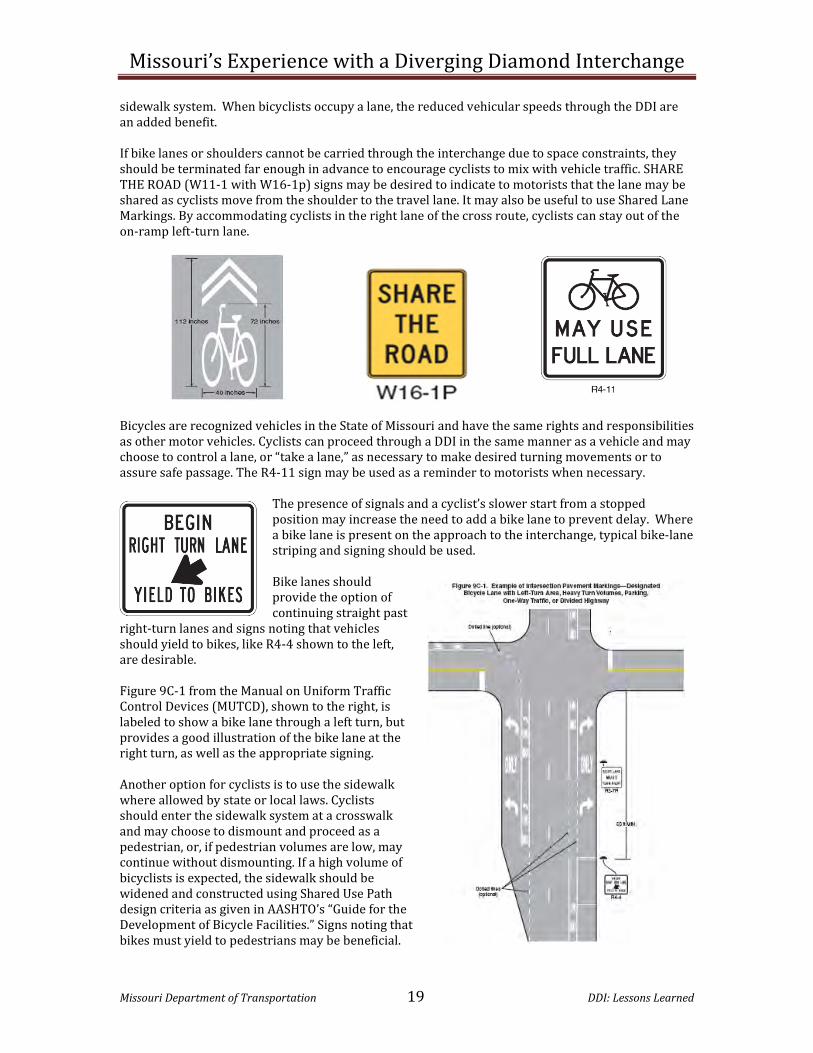
Bicycles are recognized vehicles in the State of Missouri and have the same rights and responsibilities as other motor vehicles. Cyclists can proceed through a DDI in the same manner as a vehicle and may choose to control a lane, or “take a lane,” as necessary to make desired turning movements or to assure safe passage. The R4-11 sign may be used as a reminder to motorists when necessary.
The presence of signals and a cyclist’s slower start from a stopped position may increase the need to add a bike lane to prevent delay. Where a bike lane is present on the approach to the interchange, typical bike-lane striping and signing should be used. Bike lanes should provide the option of continuing straight past
right-turn lanes and signs noting that vehicles should yield to bikes, like R4-4 shown to the left, are desirable. Figure 9C-1 from the Manual on Uniform Traffic Control Devices (MUTCD), shown to the right, is labeled to show a bike lane through a left turn, but provides a good illustration of the bike lane at the right turn, as well as the appropriate signing. Another option for cyclists is to use the sidewalk where allowed by state or local laws. Cyclists should enter the sidewalk system at a crosswalk and may choose to dismount and proceed as a pedestrian, or, if pedestrian volumes are low, may continue without dismounting. If a high volume of bicyclists is expected, the sidewalk should be widened and constructed using Shared Use Path design criteria as given in AASHTO’s “Guide for the Development of Bicycle Facilities.” Signs noting that bikes must yield to pedestrians may be beneficial.

Missouri’s Experience with a Diverging Diamond Interchange
Missouri Department of Transportation 20 DDI: Lessons Learned
Lighting Missouri lighting design principles focus on conflict areas, merge/diverge areas and raised objects. Although DDIs are approached essentially the same, uniformity of light and minimization of glare are given additional consideration. Luminaries are placed to light areas of most concern such as the ramp termini and the crossover areas. The various scenarios of DDI layout require site specific lighting provisions. Pedestrian areas should be appropriately lit for safety purposes in all cases. When a barrier protects pedestrian accommodations, embedding LED lights into the barrier wall should be considered as shown in the picture to the right. Glare Screens Glare screens are an optional device used to prevent opposing vehicles headlights from obscuring a driver’s ability to see the road as shown in Figure 2.13. Missouri’s approach has been to not install glare screens until after project completion and, then, only when a need is identified. To date, no need has been identified. For a DDI that uses a concrete barrier wall to separate opposing traffic, glare screens may be mounted on the top of the barrier wall. Glare screens may be unnecessary if the concrete barrier wall height is adequate to prevent headlights from interfering with drivers’ ability to see. Glare screens may also be used at each crossover intersection on the raised ramp islands. When glare screens are installed on ramp islands, it is important to not block the sight distance of vehicles traveling in opposing directions on the cross route.
Figure 2.13 Example of a glare screen system

Missouri’s Experience with a Diverging Diamond Interchange
Missouri Department of Transportation 21 DDI: Lessons Learned
Chapter 3 Construction Issues Phasing Though the construction phasing for a DDI can appear to be a difficult task at first, it really is no more difficult than any other construction project. As with any construction, installing a DDI at a new interchange will most likely always be easier than retrofitting an existing interchange. When retrofitting an existing diamond interchange to a DDI, asking the following questions will greatly aid in determining construction phasing:
1) Can the interchange be closed? 2) Is all (or most) of the pavement going to be replaced? 3) Is there substantial widening? 4) When is the best time to switch the traffic pattern?
Switching traffic to the DDI configuration early usually works best when most of the original pavement is going to be used in place. Simply resurfacing can also facilitate an early switch. Providing an early switch may reduce the amount of temporary pavement needed. When using most of the original pavement, consideration should be given to matching any new pavement with the existing pavement type, i.e. concrete with concrete, asphalt with asphalt. If different pavement types are used, then phasing the construction so that the joint lines are constructed to match the lane lines is most desirable. By matching the joint lines with the pavement marking, the driver is less likely to make an errant movement by following the pavement joint rather than the lane lines. Switching traffic to the DDI configuration late is usually preferable when there is considerable pavement replacement. It also seems to be preferable for half-at-a-time construction phasing. A late switch may require more temporary pavement. With adequate planning, all permanent facilities can be located outside the normal road template, temporary driving lanes and truck-turning radii for all stages of construction, i.e. signals, lighting, pull boxes. Allow as much signal and lighting work as possible without waiting until the end. Regardless of when the traffic pattern is switched, a total shutdown of the interchange is beneficial for completing the final striping and signal work. Since the raised islands are usually one of the last items constructed, delineating the future islands can aid in directing traffic in the correct direction until the islands are completed. Also by shutting down the interchange to complete these tasks, the public may be better prepared for the change in traffic pattern after the interchange is reopened.

Missouri’s Experience with a Diverging Diamond Interchange
Missouri Department of Transportation 22 DDI: Lessons Learned
Chapter 4 Operational Aspects
Access Management
As with any intersection, the access management guidelines should be taken into consideration for area expansion and development. Any proposed access modification near a DDI should be modeled to determine as best as possible the impact to the interchange operation. Oversized/Overweight Loads In Missouri, the legal width is 8 feet, 6 inches on all highways and the height is 13 feet, 6 inches on non-designated routes and 14 feet on designated routes and the length of trailer cannot exceed 53 feet. The maximum width and height allowed is 16 feet. A super load is any vehicle that exceeds 16 feet in width and height; 150 feet overall length and 160,000 gross pounds. Permits are issued for vehicles and equipment that exceed the legal limits if a safe route is available. MoDOT’s Motor Carrier Services division issues the permit. Although a DDI is not specifically designed to accommodate oversized loads, it appears to operate well and is flexible for the navigation of oversized vehicles. If the load can maneuver through a standard diamond interchange, it should be able to maneuver through a DDI. Special accommodations may have to be made such as guiding the load through, stopping other traffic to allow the load to move through or using multiple lanes to maneuver. Super loads either must “snake” their way through the mast arms or are required to remove the arms and replace them after the load has moved through the intersection with coordination by a certified signal contractor. Super loads above 160,000 pounds that intend to cross structures require a structural analysis and feasibility study. Since the signal heads in Missouri are designed to be 16 feet above the pavement, signalized intersections can accommodate every vehicle except a super load. When the cross route passes over, DDIs can present complications for routing over-height loads past bridges with vertical height restrictions that span a limited access highway. Because the
configuration of the ramp movements does not allow for re-entry to the limited access highway at the ramp termini, other provisions for an over-height load must be found.
Figure 4.1 An oversized load making a left turn onto I-44. Signal Operations
A typical DDI uses basic gap timing combined with vehicle detection in advance and at the stop bar. Interconnecting signals along the cross route will improve coordination of through movements

Missouri’s Experience with a Diverging Diamond Interchange
Missouri Department of Transportation 23 DDI: Lessons Learned
resulting in more efficient performance. Detailed information is contained in the EPG Article 902, Signals.
When signalizing the off-ramp lefts, clearance intervals for the crossover throughs can become long. The distance between the crossover intersection and the “distance to clear” for the off-ramp left turn can be significant, which increases the amount of yellow and all-red intervals. If pedestrian accommodations are in the middle of the cross route, pedestrian phases can run concurrently with the non-conflicting vehicle phase and are able to provide sufficient crossing time. Pedestrian crossings elsewhere may require longer clearance intervals and separate pedestrian phases. Phasing scheme is selected to allow the space between the crossovers to clear and, by using overlaps, the off-ramp left turns to occupy the space, whether signalized or not. Since one less signal phase is required, one controller can be used for both signalized intersections. The traditional phase assignments, however, may need to be modified. Typically, for an eight-phase traditional intersection, phases 2 and 6 are through movements for the major route and phases 4 and 8 for the side street. For the DDI, phases 2 and 6 are the through movements for the same direction of travel at each of the intersections (i.e. northbound) and phases 4 and 8 are the through movements for the other direction of travel at each of the intersections (i.e. southbound).
3 2 3 23 2 3 2
Offset Sync
Barrier
Barrier
Barrier
Barrier
Phase 8 Southbound 45 secPhase 4
Phase 6 Northbound 65 secPhase 2 Northbound 45 secPhase 4 Southbound 65 sec
Timing is an example only
Figure 4.2 Example of phase and ring assignments and intervals For signalized off-ramp left-turns, the green indication runs concurrently during the times the through movements leaving the DDI (phases 6 and 4) are on. The use of dummy phases or overlaps allows the crossovers to switch green while delaying the off-ramp green. Two controllers may be used for this scenario to allow more flexibility with phase selection.

Missouri’s Experience with a Diverging Diamond Interchange
Missouri Department of Transportation 24 DDI: Lessons Learned
Timing is an example only
Figure 4.3 Example of phase and ring assignments and intervals The decision to use one controller or two is project specific and dependent on what movements are signalized. One controller has several advantages: it eliminates communication issues between two controllers; it does not experience time-of-day issues; and it ensures the two through movements approaching the DDI on the cross route are never on at the same time. However, two controllers may be more advantageous if more phases are added due to signalizing an off-ramp turn that was not originally signalized or future expansion of the interchange such as adding an off-ramp turn lane. Also, two controllers may be required due to the electrical voltage drop based on the distance from the furthest signal head and/or detection device to the signal cabinet. Signal Optimization MoDOT’s experience with using modeling software, such as SYNCHRO, to optimize signals for the DDI has proven ineffective. Presently, signal timing is optimized manually in the field.
Missouri’s Experience with a Diverging Diamond Interchange
Missouri Department of Transportation 25 DDI: Lessons Learned
Chapter 5 Other Aspects to Consider Access Justification Report (AJR) A DDI does alter how vehicles enter and leave a limited access highway. If the limited access highway is an interstate, it is likely that FHWA will require an AJR. A formal request for determination of the exemption status for a project should be submitted to the FHWA Division office. Incident Management When an incident occurs between gores of a DDI on a limited access highway, rerouting traffic through the ramp becomes problematic because the ramp movements do not allow for re-entry to the limited access highway at the ramp termini. However, when an incident occurs at an interchange up or down stream of a DDI, the DDI can be used to facilitate a U-turn to aid in rerouting traffic.
Left Turns on Red
Because of the configuration of a DDI, a left turn either off the ramp or onto the ramp functions the same as a vehicle turning left from a one-way street. This may become an issue when the left turn from the off-ramp or to the on-ramp is signalized. In Missouri, state statues do not allow vehicular traffic to make that movement on red. They must remain “standing until a green indication is shown.” Municipalities may have ordinances that allow the left turn on red and how the state law and city ordinances apply must be considered and determined.
Maintenance
Maintenance issues of DDIs are very similar to other types of interchanges with only slight adjustments required. Maintenance practices may vary depending on whether the cross route passes over or under the limited access highway. The two maintenance areas affected the most are care for pedestrian facilities and snow plowing.
When the pedestrian facilities are in the middle of the cross route, closure of a lane may be required to fix either damaged barrier or pavement. Additionally, MoDOT’s policy is to maintain every facility it owns but in priority order. Bike and pedestrian facilities are low on that priority list and may not be cleared in the event of snow.
When the cross route passes over the limited access highway, snow plows that approach the crossovers on the cross route will be pushing snow to the outside of the roadway which is to the right. At the crossover, trucks will adjust their plows to do either one of two things. 1) Plow straight through to the other crossover and then readjust their plows again to push to the outside (right) after the second crossover; or, 2) push the snow to the left, which, between the crossovers, is the outside of the cross route, and then readjust their plows again at the second crossover. The presence of shoulders on the bridge will not likely change snow plowing practices in this case.
When the cross route passes under the limited access highway, snow plowing is very similar to when it passes over. However, the presence of shoulders gives an additional option for this scenario. When there is a wide right (inside) shoulder between the crossovers, snow may continue to be pushed to the right between the crossovers. If this approach is used, it would be advantageous to slope the shoulders inward away from the roadway so that effects of freeze/thaw cycles on the cross route are minimized. Drainage provisions would then also have to be made for the runoff in the median.
Replacing luminaires, signals and maintaining drainage facilities do not seem to present unique issues for DDIs.
Missouri’s Experience with a Diverging Diamond Interchange
Missouri Department of Transportation 26 DDI: Lessons Learned
Chapter 6 Public Involvement General Discussion Missouri citizens expect and demand an active voice in their transportation decisions and implementing DDIs is no exception. The unique and innovative nature of the DDI concept along with the public’s unfamiliarity with it can add to the complications that exist trying to foster a cooperative relationship with the public. Over time, as additional projects are developed and the number of DDIs increase statewide, public involvement in the DDI development and construction process will become less of a challenge. In the meantime, an aggressive, informative and well-targeted public involvement and education plan is the key to overcoming the most prominent disadvantages of the DDI: public confusion, unfamiliarity, skepticism and non-acceptance. Traditional guidance on the need for public meetings and hearings still applies. However, consideration should be given to conducting additional public outreach at preliminary design stage. Additionally, throughout the project development process, public involvement that exceeds the minimum warrants of a public hearing is encouraged. These efforts serve to inform the public of anticipated construction impacts and operation of the facility. As the successes of DDIs are publicized and even marketed, it is possible that the concept will begin to sell itself. An opportunity exists with each location for which a DDI is proposed to reduce the public’s unfamiliarity with the concept and to inform them of the advantages it provides. Models and Simulations Modeling and simulations should be developed and used to augment traditional displays to demonstrate the traffic movements and benefits. These will help the audience see the advantages and eased congestion a DDI provides. In retrofit situations, the computer models and simulations can be used to illustrate the contrast between the existing condition and the proposed DDI. Pedestrian and bicycle traffic should be included to demonstrate that the facility will be as conducive to the non-motorized community as any other type of interchange. Experience has shown that an initial emphasis on the windshield-level experience of driving a DDI is more effective in relaying the advantages of the interchange rather than an aerial view. Windshield-level views allow the public to realize that manuvuering through a DDI is not as complicated as it may seem. Aerial displays have their place and should be used but they can initially be confusing and work against the goal of assuring the audience of the benefits. Online Media Major project websites are traditionally used for significant projects that are of public interest or that have potentially substantial impacts. In the case of a DDI, a website serves as a particularly good opportunity to serve as a central repository for modeling, simulation and graphic visualizations that can be easily accessed by the public. Updates on status of the project, a timeline of milestones, dates for public hearings or meetings and other pertinent details can be provided in one dedicated location. Any inquiries may be easily referred to this website and may aid in meeting the public’s expectation for involvement during project development and construction. Social media tools are increasingly being used in similar fashion to major project websites. These types of sites assist in collecting public comments and providing less formal project information. They also provide an opportunity to reach a different audience who may prefer this type of media to the usual channels of communication.

Missouri’s Experience with a Diverging Diamond Interchange
Missouri Department of Transportation 27 DDI: Lessons Learned
What to Convey Regardless of format and media type chosen, it is important to emphasize the increased safety and smoother traffic flow of a DDI. The safety and efficiency of the turning movements, especially for trucks, should be highlighted to assure the public that the interchange is functional for all vehicles and modes of travel. In addition, the constructability and potential quick construction time should be specifically marketed so that both motorists and the local community know they will experience minimal disruption of service. Emphasis may need to be placed on the fact that the public’s transportation needs can still be met during construction. The cost saving associated with a smaller template, reduced bridge length or width and reduced right of way can be a particularly persuasive point. This can be put in to terms to demonstrate that the money saved by implementing a DDI over other types of interchanges can be substantial. An additional selling point is that the money saved can be applied to other road and bridge improvements. While the advantages must be clearly communicated, care should be taken not over-emphasize how outstanding the concept of the DDI is. The public unfortunately can be a skeptical group and what often sounds too good to be true, usually is. It may be prudent to include in the public involvement effort examples of situations where a DDI in the past has been considered as a solution and not chosen as appropriate. The public wants to know they are being dealt with fairly and honestly. Sample Brochure A sample brochure used in the public involvement for the Springfield DDI at I-44 and MO-13 is in Appendix F.

Missouri’s Experience with a Diverging Diamond Interchange
Missouri Department of Transportation 28 DDI: Lessons Learned
Additional Resources Examples of plans Sample sets of plans are in the appendices: Appendix A: I-44 and MO-13 in Springfield Appendix B: I-270 and Dorsett Rd in Maryland Heights Appendix C: MO-150 and Botts Rd in Kansas City Appendix D: US-60 and National Ave in Springfield Appendix E: I-70 and Wood Chapel Rd in Blue Springs Internet Resources
MoDOT EPG http://epg.modot.mo.gov Chapter 2: EPG Article 940.3 Clearance of Functional Areas of Interchanges http://epg.modot.mo.gov/index.php?title=940.3_Clearance_of_Functional_Areas_of_Interchanges EPG Category: 940 Access Management http://epg.modot.mo.gov/index.php?title=Category:940_Access_Management MoDOT Standard Plan 203.40G http://www.modot.mo.gov/business/standards_and_specs/documents/20340.pdf AASHTO Green Book Exhibit 10-70 http://epg.modot.mo.gov/files/6/64/234.2_Minimum_Acceleration_Lengths_for_Entrance_Terminals.pdf AASHTO Green Book Exhibit 10-73 http://epg.modot.mo.gov/files/a/a1/234.2_Minimum_Deceleration_Lengths_for_Exit_Terminals.pdf AASHTO Green Book Exhibit 10-71 http://epg.modot.mo.gov/files/e/eb/Speed_Change_Lane_Adjustment_Factors.pdf EPG Category: 232 Facility Selection http://epg.modot.mo.gov/index.php?title=Category:232_Facility_Selection AASHTO Green Book Exhibit 10-76 http://epg.modot.mo.gov/files/f/f0/234.2_Typical_Two-Lane_Entrance_Ramps.pdf AASHTO Green Book Exhibit 10-77 http://epg.modot.mo.gov/files/9/9b/234.2_Two_Lane_Exit_Terminals.pdf EPG Article 231.2 Clear Zones http://epg.modot.mo.gov/index.php?title=231.2_Clear_Zones EPG Category: 642 Pedestrian Facilities http://epg.modot.org/index.php?title=Category:642_Pedestrian_Facilities

Missouri’s Experience with a Diverging Diamond Interchange
Missouri Department of Transportation 29 DDI: Lessons Learned
Americans with Disabilities Act Accessibility Guidelines (ADAAG) http://www.access-board.gov/adaag/html/adaag.htm Public Right of Way Accessibility Guidelines (PROWAG) http://www.access-board.gov/prowac/ Manual on Uniform Traffic Control Devices (MUTCD) www.mutcd.fhwa.dot.gov/ Chapter 4: EPG Category 902 Signals http://epg.modot.mo.gov/index.php?title=Category:902_Signals Chapter 6: Traditional Display (brochure) – Kansas Expressway DDI http://www.modot.mo.gov/springfield/major_projects/Greene/documents/I-44-Route13DDI.pdf Windshield-level Animation – Front Street DDI http://www.youtube.com/user/modotvideo#p/search/0/NANacKPO0Q4 Aerial View Video – Kansas Expressway DDI http://www.youtube.com/user/modotvideo#p/search/1/B5JtZMPTNAY Major Project Website – Woods Chapel DDI http://www.modot.mo.gov/kansascity/major_projects/Woods_Chapel_Diverging_Diamond.htm MoDOT Facebook http://www.modot.mo.gov/facebook/index.htm External Documents “Tech Brief: Double Crossover Diamond Interchange.” Federal Highway Administration. 2009. Online:
http://www.fhwa.dot.gov/publications/research/safety/09054/09054.pdf
“Tech Brief: Drivers’ Evaluation of the Diverging Diamond Interchange.” Federal Highway Administration. 2008. Online: http://www.tfhrc.gov/safety/pubs/07048/07048.pdf “Design and Operational Performance of Double Crossover Intersection and Diverging Diamond Interchange.” Praveen K. Edara. Transportation Research Board. 2005. Online: http://tinyurl.com/yb9cjkh
“Innovative Diamond Interchange Designs: How to Increase Capacity and Minimize Cost.” David Stanek. Institute of Transportation Engineers. 2007. Online:
http://tinyurl.com/y9yum2o
“Traffic and Operational Comparison of Single-Point and Diverging Diamond Interchanges.” Praveen K. Edara. Transportation Research Board. 2009. “Innovations of the Year: Diverging Diamond Intersection.” Popular Science. 2009. Online: http://www.popsci.com/bown/2009/product/diverging-diamond-interchange “Alternative Intersections/Interchanges: Informational Report”, Federal Highway Administration, 2010. Online: http://www.fhwa.dot.gov/publications/research/safety/09060/

Missouri’s Experience with a Diverging Diamond Interchange
Missouri Department of Transportation 30 DDI: Lessons Learned
Appendices
Appendix A ..................................................................................................................... A-1 to A-25 Sample Set of Plans for I-44 and MO-13 (Springfield) Appendix B ..................................................................................................................... B-1 to B-14 Sample Set of Plans for I-270 and Dorsett Rd (Maryland Heights) Appendix C ...................................................................................................................... C-1 to C-37 Sample Set of Plans for MO-150 and Botts Rd (Kansas City) Appendix D ..................................................................................................................... D-1 to D-13 Sample Set of Plans for US-60 and National Ave (Springfield) Appendix E ..................................................................................................................... E-1 to E-12 Sample Set of Plans for I-70 and Wood Chapel Rd (Blue Springs) Appendix F ...................................................................................................................... F-1 to F-2 Brochure for Public Relations for I-44 and MO-13