mission assurance requirements (mar) for the large … mar 5-28-03.pdf · 433-mar-0001 check the...
TRANSCRIPT

433-MAR-0001
CHECK THE GLAST PROJECT WEBSITE AT
http://glast.gsfc.nasa.gov/project/cm/mcdl TO VERIFY THAT THIS IS THE CORRECT VERSION PRIOR TO USE.
GAMMA-RAY LARGE AREA SPACE TELESCOPE
(GLAST) PROJECT
MISSION ASSURANCE REQUIREMENTS (MAR)
FOR THE LARGE AREA TELESCOPE (LAT)
REVISION A
April 8, 2003
GODDARD SPACE FLIGHT CENTER GREENBELT, MARYLAND

433-MAR-0001
CHECK THE GLAST PROJECT WEBSITE AT
http://glast.gsfc.nasa.gov/project/cm/mcdl TO VERIFY THAT THIS IS THE CORRECT VERSION PRIOR TO USE.
GAMMA-RAY LARGE AREA SPACE TELESCOPE (GLAST)
PROJECT
MISSION ASSURANCE REQUIREMENTS (MAR)
FOR THE
LARGE AREA TELESCOPE (LAT)
REVISION A
April 8, 2003
NASA Goddard Space Flight Center
Greenbelt, Maryland

433-MAR-0001
CHECK THE GLAST PROJECT WEBSITE AT http://glast.gsfc.nasa.gov/project/cm/mcdl TO VERIFY THAT THIS IS THE CORRECT VERSION PRIOR TO USE.
GLAST Project Mission Assurance Requirements (MAR) for
the Large Area Telescope (LAT), PHASE C/D/E
Prepared by: Original Signed ______________________________________________________ Ronald E.Kolecki Date Systems Assurance Manager Concurrence by: Original Signed ______________________________________________________ Bernie Graf Date LAT Instrument Manager Original Signed ______________________________________________________ William Althouse Date LAT Project Manager Approved by: Original Signed ______________________________________________________ Kevin Grady Date GLAST Project Manager

433-MAR-0001
CHECK THE GLAST PROJECT WEBSITE AT http://glast.gsfc.nasa.gov/project/cm/mcdl TO VERIFY THAT THIS IS THE CORRECT VERSION PRIOR TO USE.
Revision A ii April 8, 2003
CHANGE RECORD PAGE
DOCUMENT TITLE: GLAST Project Mission Assurance Requirements (MAR) for the Large Area Telescope (LAT), PHASE C/D/E DOCUMENT DATE: 04/08/02
ISSUE DATE PAGES AFFECTED DESCRIPTION
Original
10/26/00
All
Baseline. CCR 433-0002
Revision A 04/08/03 All Updated document for phases C/D/E. CCR 433-0145.

433-MAR-0001
CHECK THE GLAST PROJECT WEBSITE AT http://glast.gsfc.nasa.gov/project/cm/mcdl TO VERIFY THAT THIS IS THE CORRECT VERSION PRIOR TO USE.
Revision A iii April 8, 2003
TABLE OF CONTENTS
CHAPTER 1. OVERALL REQUIREMENTS ...............................................................................1 1.0 OVERVIEW OF CHAPTER 1 .........................................................................................................................1 1.1 DESCRIPTION OF OVERALL REQUIREMENTS..........................................................................................1 1.2 USE OF PREVIOUSLY DESIGNED, FABRICATED, OR FLOWN HARDWARE............................................1 1.3 SURVEILLANCE OF THE CONTRACTOR....................................................................................................2 1.4 APPLICABLE DOCUMENTS (CHAPTER 13) ................................................................................................2 1.5 ACRONYMS AND GLOSSARY (CHAPTER 14) ............................................................................................2 1.6 CONTRACT DELIVERY REQUIREMENTS LIST (CDRL)..............................................................................2 1.7 ADDENDUM A: GROUND DATA SYSTEMS ASSURANCE GUIDELINES...................................................2
CHAPTER 2. SYSTEM SAFETY REQUIREMENTS...................................................................3 2.0 OVERVIEW OF CHAPTER 2 .........................................................................................................................3 2.1 SYSTEM SAFETY REQUIREMENTS............................................................................................................3 2.2 SYSTEM SAFETY DELIVERABLES..............................................................................................................4
CHAPTER 3. TECHNICAL REVIEW REQUIREMENTS.............................................................5 3.0 OVERVIEW OF CHAPTER 3 .........................................................................................................................5 3.1 GENERAL REQUIREMENTS ........................................................................................................................5 3.2 GSFC SYSTEM REVIEW REQUIREMENTS .................................................................................................6 3.3 GSFC SYSTEM REVIEW PROGRAM ...........................................................................................................6 3.4 IMPLEMENTATION .......................................................................................................................................6
3.4.1 System Review Program (SRP) ................................................................................6 3.4.2 Structure and Function of the System Review Program ...........................................6 3.4.3 System Review Schedule..........................................................................................8 3.4.4 System Safety ...........................................................................................................8
3.5 DEVELOPER REVIEW REQUIREMENTS.....................................................................................................8 CHAPTER 4. DESIGN VERIFICATION REQUIREMENTS.......................................................10
4.0 OVERVIEW OF CHAPTER 4 .......................................................................................................................10 4.1 GENERAL REQUIREMENTS ......................................................................................................................10 4.2 DOCUMENTATION REQUIREMENTS........................................................................................................11
4.2.1 Performance Verification Plan.................................................................................11 4.2.2 Performance Verification Procedures......................................................................12 4.2.3 Instrument Performance Verification Reports .........................................................13
4.3 ELECTRICAL FUNCTIONAL TEST REQUIREMENTS................................................................................13 4.3.1 Electrical Interface Tests .........................................................................................13 4.3.2 Comprehensive Performance Tests (CPT’s)...........................................................13 4.3.3 Limited Performance Tests (LPT’s).........................................................................14 4.3.4 Aliveness Tests .......................................................................................................14 4.3.5 Performance Operating Time and Failure-Free Performance Testing ....................14 4.3.6 Testing of Limited-Life Electrical Elements .............................................................14
4.4 STRUCTURAL AND MECHANICAL REQUIREMENTS...............................................................................14 4.4.1 Structural Loads ......................................................................................................15 4.4.2 Vibroacoustics .........................................................................................................15 4.4.3 Sinusoidal Sweep Vibration Verification..................................................................16 4.4.4 Mechanical Shock ...................................................................................................16 4.4.5 Mass Properties ......................................................................................................16
4.5 ELECTROMAGNETIC COMPATIBILITY (EMC) REQUIREMENTS ............................................................16 4.6 VACUUM, THERMAL, AND HUMIDITY REQUIREMENTS..........................................................................16
4.6.1 Thermal Vacuum Balance Testing ..........................................................................18 4.6.2 Thermal Vacuum Cycle Testing ..............................................................................19

433-MAR-0001
CHECK THE GLAST PROJECT WEBSITE AT http://glast.gsfc.nasa.gov/project/cm/mcdl TO VERIFY THAT THIS IS THE CORRECT VERSION PRIOR TO USE.
Revision A iv April 8, 2003
4.6.3 Transportation and Storage Temperature-Humidity Environment...........................19 4.7 SPACECRAFT/PAYLOAD VERIFICATION DOCUMENTATION.................................................................19
CHAPTER 5. ELECTRONIC PACKAGING AND PROCESSES REQUIREMENTS ................20 5.0 OVERVIEW OF CHAPTER 5 .......................................................................................................................20 5.1 GENERAL....................................................................................................................................................20 5.2 WORKMANSHIP..........................................................................................................................................20 5.3 NEW/ADVANCED PACKAGING TECHNOLOGIES ....................................................................................21
CHAPTER 6 PARTS REQUIREMENTS ...................................................................................22 6.0 OVERVIEW OF CHAPTER 6 .......................................................................................................................22 6.1 GENERAL....................................................................................................................................................22 6.2 ELECTRICAL, ELECTRONIC, AND ELECTROMECHANICAL (EEE) PARTS ............................................22
6.2.1 Parts Control Board.................................................................................................22 6.2.2 Parts Selection and Processing ..............................................................................23 6.2.3 Derating...................................................................................................................24 6.2.4 Radiation Hardness.................................................................................................24 6.2.5 Verification Testing..................................................................................................24 6.2.6 Destructive Physical Analysis..................................................................................24 6.2.7 Failure Analysis .......................................................................................................24 6.2.8 Parts Age Control ....................................................................................................25
6.3 PARTS LISTS ..............................................................................................................................................25 6.3.1 Project Approved Parts List.....................................................................................25 6.3.2 Parts Identification List ............................................................................................25
6.4 ALERTS .......................................................................................................................................................27 CHAPTER 7. MATERIALS, PROCESSES, AND LUBRICATION REQUIREMENTS..............28
7.0 OVERVIEW OF CHAPTER 7 .......................................................................................................................28 7.1 GENERAL REQUIREMENTS ......................................................................................................................28
7.1.1 Parts and Material Control Board ............................................................................28 7.2 MATERIALS SELECTION REQUIREMENTS ..............................................................................................28
7.2.1 Compliant Materials.................................................................................................29 7.2.2 Non-compliant Materials..........................................................................................29 7.2.3 Conventional Applications .......................................................................................29 7.2.4 Non-conventional Applications ................................................................................29 7.2.5 Polymeric Materials .................................................................................................30 7.2.6 Inorganic Materials ..................................................................................................30 7.2.7 Lubrication...............................................................................................................31
7.3 PROCESS SELECTION REQUIREMENTS.................................................................................................31 7.4 PROCUREMENT REQUIREMENTS ...........................................................................................................31
7.4.1 Purchased Raw Materials .......................................................................................31 7.4.2 Raw Materials Used in Purchased Products ...........................................................32
CHAPTER 8. RELIABILITY REQUIREMENTS ........................................................................35 8.0 OVERVIEW OF CHAPTER 8 .......................................................................................................................35 8.1 GENERAL REQUIREMENTS ......................................................................................................................35 8.2 RELIABILITY ANALYSES ............................................................................................................................35
8.2.1 Failure Modes and Effects Analysis and Critical Items List .....................................36 8.2.2 Parts Stress Analyses .............................................................................................37 8.2.3 Worst Case Analyses ..............................................................................................37 8.2.4 Reliability Assessments...........................................................................................37
8.3 ANALYSIS OF TEST DATA .........................................................................................................................38 8.3.1 Trend Analyses .......................................................................................................38 8.3.2 Analysis of Test Results ..........................................................................................38

433-MAR-0001
CHECK THE GLAST PROJECT WEBSITE AT http://glast.gsfc.nasa.gov/project/cm/mcdl TO VERIFY THAT THIS IS THE CORRECT VERSION PRIOR TO USE.
Revision A v April 8, 2003
8.4 LIMITED-LIFE ITEMS ..................................................................................................................................39 CHAPTER 9. QUALITY ASSURANCE REQUIREMENTS .......................................................40
9.0 QUALITY MANAGEMENT SYSTEM............................................................................................................40 9.1 QA MANAGEMENT SYSTEM REQUIREMENTS AUGMENTATION...........................................................40
9.1.1 Section 4.4.4: ..........................................................................................................40 9.1.2 Section 4.6.3: ..........................................................................................................40 9.1.3 Section 4.13.2: ........................................................................................................40
CHAPTER 10. CONTAMINATION CONTROL REQUIREMENTS ...........................................41 10.0 OVERVIEW OF CHAPTER 10 .....................................................................................................................41 10.1 GENERAL....................................................................................................................................................41 10.2 CONTAMINATION CONTROL PLAN...........................................................................................................41 10.3 MATERIAL OUTGASSING ..........................................................................................................................41 10.4 THERMAL VACUUM BAKEOUT..................................................................................................................41 10.5 HARDWARE HANDLING.............................................................................................................................41
CHAPTER 11. SOFTWARE ASSURANCE REQUIREMENTS ................................................43 11.0 OVERVIEW OF CHAPTER 11 .....................................................................................................................43 11.1 GENERAL....................................................................................................................................................43 11.2 QUALITY SYSTEM AUGMENTATIONS ......................................................................................................43
11.2.1 Augmentation to Section 4.1.3, Joint Reviews ..................................................................43 11.2.2 Augmentation to Section 4.14, Corrective Action..............................................................44 11.2.3 Augmentation to Section 4.8, Configuration Management................................................44 11.2.4 Augmentation to Section 4.10.4, Inspection and Testing ..................................................44 11.2.5 Augmentation to Section 4.10.4, Final Inspection and Testing .........................................44 11.2.6 Augmentation to Section 4.4.5, Design Outputs................................................................44
11.3 GFE, EXISTING AND PURCHASED SOFTWARE ......................................................................................44 11.4 SOFTWARE SAFETY ..................................................................................................................................45 11.5 STATUS REPORTING.................................................................................................................................45
CHAPTER 12. RISK MANAGEMENT REQUIREMENTS.........................................................46 12.0 OVERVIEW OF CHAPTER 12 .....................................................................................................................46 12.1 GENERAL REQUIREMENTS ......................................................................................................................46 12.2 PROBABILISTIC RISK ASSESSMENT (PRA) .............................................................................................47 12.3 RISK ASSESSMENT ...................................................................................................................................47
CHAPTER 13. REFERENCE DOCUMENTS LIST ...................................................................48 CHAPTER 14. ACRONYMS AND GLOSSARY........................................................................50
14.1 ACRONYMS ................................................................................................................................................50 14.2 DEFINITIONS ..............................................................................................................................................53
ADDENDUM A: GROUND DATA SYSTEMS ASSURANCE GUIDELINES ............................59 A.1 OVERVIEW..................................................................................................................................................59 A.2 GOVERNMENT FURNISHED, EXISTING AND PURCHASED ITEMS........................................................59 A.3 COMMERCIAL OFF THE SHELF (COTS) MANAGEMENT.........................................................................59 A.4 FABRICATED HARDWARE.........................................................................................................................60 A.5 VERIFICATION AND VALIDATION..............................................................................................................60 A.6 TESTING......................................................................................................................................................61 A.7 CORRECTIVE ACTION ...............................................................................................................................62 A.8 REVIEWS.....................................................................................................................................................62 A.9 SOFTWARE CONFIGURATION MANAGEMENT (SCM) ............................................................................62 A.10 ELECTROMAGNETIC COMPATIBILITY CONTROL...............................................................................63 A.11 RELIABILITY AND MAINTAINABILITY ....................................................................................................63
A.11.1 Reliability Allocations ...........................................................................................63 A.11.2 Reliability Prediction.............................................................................................63

433-MAR-0001
CHECK THE GLAST PROJECT WEBSITE AT http://glast.gsfc.nasa.gov/project/cm/mcdl TO VERIFY THAT THIS IS THE CORRECT VERSION PRIOR TO USE.
Revision A vi April 8, 2003
A.11.3 Reliability Evaluation and Acceptance testing......................................................64 A.11.4 Maintainability Allocation......................................................................................64 A.11.5 Maintainability Models..........................................................................................64 A.11.6 Maintainability Prediction .....................................................................................65 A.11.7 Maintainability Design Criteria..............................................................................65
A.12 GOVERNMENT PROPERTY CONTROL.................................................................................................65

433-MAR-0001
CHECK THE GLAST PROJECT WEBSITE AT http://glast.gsfc.nasa.gov/project/cm/mcdl TO VERIFY THAT THIS IS THE CORRECT
VERSION PRIOR TO USE. Revision A 1 April 8, 2003
CHAPTER 1. Overall Requirements 1.0 OVERVIEW OF CHAPTER 1 Chapter 1 addresses the overall program requirements including the justification of “heritage” or previously designed, fabricated, or flown hardware; surveillance of the contractor; applicable documents (Chapter 13); and document acronyms and glossary (Chapter 14). The LAT Contract Delivery Requirement List (CDRL) identifies those deliverables that will be part of the System Safety and Mission Assurance Program for the Large Area Telescope. In the event of a contradiction between the S&MA requirements stated in the LAT MAR and other documentation (developer or Government), the MAR shall take precedence. The deliverable item (DID) related to this chapter is:
Item DID No.
MAR Reference Sections
Notes
Performance Assurance Implementation Plan (PAIP) or Performance Assurance Plan (PAP)
301 1.1, 2.1, 6.1, 7.1, 10.1, 12.1
May include other plans referenced in this.
DELETED 302 1.1 DESCRIPTION OF OVERALL REQUIREMENTS The developer is required to plan and implement an organized System Safety and Mission Assurance Program that encompasses (1) all flight hardware, either designed/built by developer or furnished by the Government, from project initiation through launch operations, (2) to the extent necessary to assure the integrity and safety of flight items, the ground system that interfaces with flight equipment items, and (3) all software critical for mission success. This plan shall be documented in a Performance Assurance Implementation Plan (PAIP) or Performance Assurance Plan (PAP). (Refer to the CDRL, DID 301.) If the LAT MAR conflicts with any developer, subcontractor, etc. document; this document will take precedence. Managers of the assurance activities will have direct access to developer management independent of project management, with the functional freedom and authority to interact with all other elements of the project. Issues requiring project management attention should be addressed with the developer(s) through the Project Manager(s) and/or Contracting Officer Technical Representative(s). The Systems Safety and Mission Assurance Program is applicable to the project and its associated contractors, subcontractors, and developers. 1.2 USE OF PREVIOUSLY DESIGNED, FABRICATED, OR FLOWN HARDWARE When hardware that was designed, fabricated, or flown on a previous project is considered to have demonstrated compliance with some or all of the requirements of this document such that

433-MAR-0001
CHECK THE GLAST PROJECT WEBSITE AT http://glast.gsfc.nasa.gov/project/cm/mcdl TO VERIFY THAT THIS IS THE CORRECT VERSION PRIOR TO USE.
Revision A 2 April 8, 2003
certain tasks need not be repeated, the developer will be required demonstrate how the hardware complies with requirements prior to being relieved from performing any tasks. 1.3 SURVEILLANCE OF THE CONTRACTOR The work activities, operations, and documentation performed by the developer or his suppliers are subject to evaluation, review, audit, and inspection by government-designated representatives from GSFC, the Government Inspection Agency (GIA), or an independent assurance contractor (IAC). GSFC will delegate in-plant responsibilities and authority to those agencies via a letter of delegation, or the GSFC contract with the IAC. The developer, upon request, will provide government assurance representatives with documents, records, and equipment required to perform their assurance and safety activities. The developer will also provide the government assurance representative(s) with an acceptable work area within developer facilities. 1.4 APPLICABLE DOCUMENTS (CHAPTER 13) To the extent referenced herein, applicable portions of the documents listed in Chapter 13 form a part of this document. 1.5 ACRONYMS AND GLOSSARY (CHAPTER 14) Chapter 14 defines acronyms and terms as applied in this document. 1.6 CONTRACT DELIVERY REQUIREMENTS LIST (CDRL) The CDRL contains Data Item Descriptions (DID’s) which describe data deliverable to the GSFC Project Office. The “DID numbers” cited in this document refer to the “CDRL numbers” listed on the DID’s contained in the CDRL. Deliverables may be received/reviewed by GSFC personnel at either GSFC or at the developer’s facility as specified in the respective DID. References to delivery to or approval/review by “the Government” refer to GSFC. The following definitions apply with respect to assurance deliverables: Deliver for Approval: Documents in this category require written GSFC approval prior to
use. Requirements for resubmission shall be as specified in the letter(s) of disapproval.
Deliver for Information/Review: Documents in this category require receipt by GSFC for
the purpose of determining current program status, progress, and future planning requirements. When Government evaluations reveal inadequacies, the developer will be directed to correct the documents.
1.7 ADDENDUM A: GROUND DATA SYSTEMS ASSURANCE GUIDELINES This Addendum specifically addresses Ground Data System (GDS) Assurance Guidelines for the LAT Instrument Operations Center (IOC). However, if any Level 0 processing is performed by the LAT IOC, this Addendum becomes the “Ground Data Systems Assurance Requirements” with all “guidelines” becoming mandatory requirements.

433-MAR-0001
CHECK THE GLAST PROJECT WEBSITE AT http://glast.gsfc.nasa.gov/project/cm/mcdl TO VERIFY THAT THIS IS THE CORRECT VERSION PRIOR TO USE.
Revision A 3 April 8, 2003
CHAPTER 2. System Safety Requirements 2.0 OVERVIEW OF CHAPTER 2 Chapter 2 addresses the System Safety Requirements that will be part of the System Safety and Mission Assurance Program for the GLAST Project. The DID’s related to this chapter are:
Item DID No.
MAR Reference Sections
Notes
System Safety Program Plan (SSPP)
303 2.1, 2.2
Preliminary Hazard Analysis (PHA) 304 2.2 Operating & Support Hazard Analysis (O&SHA)
327 2.2
Hazard Control Verification Log 328 2.2 Safety Assessment) 329 2.2 Ground Operations Plan Inputs to Spacecraft Contractor
330 2.2
Safety Noncompliance Reports 305 2.2 2.1 SYSTEM SAFETY REQUIREMENTS Flight hardware and software systems developers as well as GSE developers/users shall implement a system safety program in accordance with the requirements imposed by the appropriate launch range and the launch vehicle manufacturer or launch service provider. The requirements may be tailored the specific mission with the concurrence of the applicable launch range safety organization. The developer will prepare a System Safety Program Plan (SSPP) which will describe their system safety program within their facility and, to the extent required, at the spacecraft integrator’s facility and the launch facilities. (Refer to the CDRL, DID 303.) The SSPP may be incorporated into the Performance Assurance Implementation Plan. (Refer to the CDRL, DID 301.) The safety program will be in accordance with the requirements of EWR 127-1 and KHB 1710.2D. The following are mandatory compliance requirements for hardware and software to be launched out of the Eastern Range on any of the various launch vehicles/launch services. The Project Manager ensures compliance with the requirements and certifies to the launch range, in the form of the Missile Systems Safety Data Package (MSPSP), that all of the requirements have been met. Top level Safety Requirements documents for the GLAST launch are:
a. EWR 127-1, “Eastern and Western Range Safety Requirements” which defines the Range Safety Program responsibilities and authorities and which delineates policies,

433-MAR-0001
CHECK THE GLAST PROJECT WEBSITE AT http://glast.gsfc.nasa.gov/project/cm/mcdl TO VERIFY THAT THIS IS THE CORRECT VERSION PRIOR TO USE.
Revision A 4 April 8, 2003
processes, and approvals for all activities from the design concept through test, check-out, assembly, and the launch of launch vehicles and payloads to orbital insertion or impact from or onto the Eastern Range (ER) or the Western Range (WR). It also establishes minimum design, test, inspection, and data requirements for hazardous and safety critical launch vehicles, payloads, and ground support equipment, systems, and materials for ER/WR users.
b. KHB 1710.2D, “Kennedy Space Center Safety Practices Handbook” which specifies
and establishes safety policies and requirements essential during design, operation, and maintenance activities at KSC and other areas where KSC has jurisdiction.
As appropriate, any testing performed at GSFC will comply with the safety requirements contained in 5405-048-98, the Mechanical Systems Center Safety Manual. Satisfactory compliance with the above requirements is required to gain payload and GSE access to the launch site and the subsequent launch. The developer will participate in Project activities associated with compliance to NPD 8710.3, NASA Policy for Limiting Orbital Debris Generation. Design and safety activities will take into account the instrument’s impact on the spacecraft’s ability to conform to debris generation requirements. 2.2 SYSTEM SAFETY DELIVERABLES Refer to the CDRL, DID’s 303 through 305 as well as to DID’s 327 through 330 the System Safety deliverables.

433-MAR-0001
CHECK THE GLAST PROJECT WEBSITE AT http://glast.gsfc.nasa.gov/project/cm/mcdl TO VERIFY THAT THIS IS THE CORRECT VERSION PRIOR TO USE.
Revision A 5 April 8, 2003
CHAPTER 3. Technical Review Requirements 3.0 OVERVIEW OF CHAPTER 3 Chapter 3 addresses the Technical Review Requirements that will be part of the System Safety and Mission Assurance Program for the GLAST Project. The DID’s related to this chapter are:
Items DID No.
MAR Reference Sections
Notes
Instrument Systems Requirement Review (SRR) Instrument Preliminary Design Review (PDR) Software PDR (may be part of PDR) Instrument Critical Design Review (CDR) Software CDR (may be part of CDR) Instrument Pre-Environmental Review (PER)
3.2, 3.4.2.2, 3.4.2.3
The deliverables for each of these instrument level reviews include: • The presentation
package • Supporting data • Technical and
logistics support
Mission SRR Mission PDR Mission CDR
3.2, 3.4.2.2, 3.4.2.4, 3.4.2.6
Observatory PER Observatory PSR 3.2, 3.4.2.2, 3.4.2.4
Mission Operations Review Flight Operations Review Launch Readiness Review
3.2, 3.4.2.2, 3.4.2.4, 3.4.2.6
Safety Reviews 3.4.4
The developer’s level of participation will be determined by GSFC Project Office and/or spacecraft contractor. Developer inputs will be blended into deliverables.
Component and Subsystem Peer Reviews including Packaging Reviews
Reports only are deliverable.
Invitation to Peer/Packaging Review
306
3.5
3.1 GENERAL REQUIREMENTS The developer will support a series of comprehensive system-level design reviews that are conducted by the GSFC Systems Review Office (SRO). The reviews cover all aspects of flight and ground hardware, software, and operations for which the developer has responsibility. (See Section 3.3.) In addition, each developer will conduct a program of planned, scheduled and documented component and subsystem reviews of all aspects of his area of responsibility. (Refer to CDRL, DID 306.)

433-MAR-0001
CHECK THE GLAST PROJECT WEBSITE AT http://glast.gsfc.nasa.gov/project/cm/mcdl TO VERIFY THAT THIS IS THE CORRECT VERSION PRIOR TO USE.
Revision A 6 April 8, 2003
3.2 GSFC SYSTEM REVIEW REQUIREMENTS For each specified system-level review conducted by the GSFC SRO, the developer will:
a. Develop and organize material for oral presentation to the GSFC review team. Copies
of the presentation material will be available at each review. b. Support splinter review meetings resulting from the major review. c. Produce written responses to recommendations and action items resulting from the
review. d. Summarize, as appropriate, the results of the Developer Reviews at the component
and subsystem level.
3.3 GSFC SYSTEM REVIEW PROGRAM The Office of Systems Safety and Mission Assurance (OSSMA) System Review Program (SRP) guidelines consists of individual, periodic reviews of all GSFC managed flight missions, flight instruments, flight spacecraft, ground systems which interface with flight hardware, unique flight support equipment, and their associated software including hardware supplied to GSFC-managed flight missions by other organizations or by another NASA Center. 3.4 IMPLEMENTATION 3.4.1 SYSTEM REVIEW PROGRAM (SRP) The primary objective of the SRP is to enhance the probability of success of GSFC missions. This objective will be achieved by bringing to bear on each GSFC-managed flight mission the cumulative knowledge of a team of engineers and scientists who have had extensive prior experience with the particular types of systems and functions involved. While the design review is technically oriented, proper consideration will be given to constraints operating on the mission. These reviews will assure that each mission has the benefit of Center-wide experience gained on other missions. 3.4.2 STRUCTURE AND FUNCTION OF THE SYSTEM REVIEW PROGRAM 3.4.2.1 System Review Plan The Chief of the SRO, in conjunction with the individual Project Manager, and/or Principal Investigator (PI) will develop system review requirements to be documented in the project mission assurance requirements. The Chief of the SRO may waive the requirement for some of these reviews based primarily on considerations of system complexity, criticality, extent of technological design, (e.g., state-of-the-art), previous flight history, mission objectives, and any mandated constraints.
3.4.2.2 The System Review Team (SRT) The SRT will include personnel experienced in subsystem design, systems engineering and integration, testing, and all other applicable disciplines. The review chairperson, in concert with the Project Manager and/or PI, and other Directorates, appoints independent key technical experts as review team members. Personnel outside the Center may be invited as members of

433-MAR-0001
CHECK THE GLAST PROJECT WEBSITE AT http://glast.gsfc.nasa.gov/project/cm/mcdl TO VERIFY THAT THIS IS THE CORRECT VERSION PRIOR TO USE.
Revision A 7 April 8, 2003
the SRT if it is felt their expertise will enhance the SRT. The reviews will be based upon an appropriate selection from the following system reviews:
a. System Requirements Review (SRR)--This review is keyed to the beginning of the design, assembly, and test phase to verify that the appropriate plans and requirement specifications are in place, well documented, and understood by all parties.
b. Preliminary Design Review (PDR)--This review occurs early in the design phase by
prior to manufacture of engineering hardware and the detail design of associated software. Where applicable, it should include the results of test bedding, breadboard testing, and software prototyping. It should also include the status of the progress in complying with the launch range safety requirements. At PDR the flight hardware developer should have identified and documented all of the hazards associated with the flight hardware.
c. Critical Design Review (CDR)--This review occurs after the design has been
completed but prior to the start of manufacturing flight components or the coding of software. It will emphasize implementations of design approaches as well as test plans for flight systems including the results of engineering model testing. The developer is also required to present the status of the controls for the safety hazards presented in the PDR and the status of all presentations to the launch range.
d. Mission Operations Review (MOR)--This mission-oriented review will normally take
place prior to significant integration and test of the flight system and ground system. Its purpose is to review the status of the system components, including the ground system and its operational interface with the flight system. Discussions will include mission integration, test planning and the status of preparations for flight operations.
e. Pre-Environmental Review (PER)--This review occurs prior to the start of
environmental testing of the protoflight or flight system. The primary purpose of this review is to establish the readiness of the system for test and evaluate the environmental test plans.
f. Pre-Shipment Review (PSR)--This review will take place prior to shipment of the
instrument for integration with the spacecraft and for shipment of the spacecraft to the launch range. The PSR will concentrate on system performance during qualification or acceptance testing. The flight hardware developer is also required to present the status of the tracking of the safety items listed in the validation tracking log, the status of deliverable documents to the launch range and the status of presentations and any subsequent launch range issues or approvals prior to sending flight hardware to the range.
g. Flight Operations Review (FOR)--While all of the previous reviews involve operations,
this review will emphasize the final orbital operation plans as well as the compatibility of the flight components with ground support equipment and ground network, including summary results of the network compatibility tests.
h. Launch Readiness Review (LRR)--This review is to assess the overall readiness of the
total system to support the flight objectives of the mission. The LRR is usually held at the launch site 2 to 3 days prior to launch.

433-MAR-0001
CHECK THE GLAST PROJECT WEBSITE AT http://glast.gsfc.nasa.gov/project/cm/mcdl TO VERIFY THAT THIS IS THE CORRECT VERSION PRIOR TO USE.
Revision A 8 April 8, 2003
The SRP will consist of SRR, PDR, CDR, PER, and PSR. The SRP for each spacecraft will generally consist of SRR, PDR, CDR, MOR, PER, PSR, FOR, and LRR. Instrument contractor personnel shall attend and participate in these reviews to the extent required. The SRP for flight equipment supplied to GSFC by another organization (non-NASA or JPL) will be treated as if it were GSFC equipment to fly on a GSFC spacecraft and will be subject to the requisite GSFC review program. Tailoring of the review program is permitted by mutual agreement to meet the intent of the GSFC SRP. Tailoring is subject to approval of the Chief of the SRO. The SRP for new, project unique ground systems will consist of PDR and CDR. The ground system is also a major subject of the mission-oriented reviews SRR, MOR, FOR, and LRR. Instrument contractor personnel shall attend and participate in these reviews to the extent required. Generic mission operations and data systems facilities newly developed or significantly modified will normally be reviewed by an appropriate Directorate review team. 3.4.3 SYSTEM REVIEW SCHEDULE The system reviews will be conducted on a schedule determined by the Chief, SRO, after consultation with the appropriate Project Manager and/or PI. 3.4.4 SYSTEM SAFETY The safety aspects of the systems being reviewed are a normal consideration in the system evaluations conducted by the SRP. At each appropriate review, the project will demonstrate understanding of and compliance with the applicable launch range requirements, list any known noncompliance’s and provide justification for any expected waiver conditions. In addition, the project will present the results of any safety reviews held with the Eastern Test Range. 3.5 DEVELOPER REVIEW REQUIREMENTS The developer will implement a program of peer reviews for missions at the subsystem levels. The program will, as a minimum, consist of a Preliminary Design Review and a Critical Design Review. In addition, packaging reviews should be conducted on all electrical and electromechanical components in the flight system. The PDR and CDR will evaluate the ability of the subsystem to successfully perform its function under operating and environmental conditions during both testing and flight. The results of parts stress analyses and component packaging reviews, including the results of associated tests and analyses, will be discussed at the subsystem PDR’s and CDR’s. The packaging reviews will specifically address the following:
a. Placement, mounting, and interconnection of EEE parts on circuit boards or substrates.
b. Structural support and thermal accommodation of the boards and substrates and their interconnections in the component design.
c. Provisions for protection of the parts and ease of inspection.

433-MAR-0001
CHECK THE GLAST PROJECT WEBSITE AT http://glast.gsfc.nasa.gov/project/cm/mcdl TO VERIFY THAT THIS IS THE CORRECT VERSION PRIOR TO USE.
Revision A 9 April 8, 2003
Developer reviews will be conducted by personnel who are not directly responsible for design of the hardware under review. GSFC reserves the right to attend the peer reviews and requires 10 working days notification. The results of the reviews will be documented and the documents will be made available for review at the developer’s facility.

433-MAR-0001
CHECK THE GLAST PROJECT WEBSITE AT http://glast.gsfc.nasa.gov/project/cm/mcdl TO VERIFY THAT THIS IS THE CORRECT VERSION PRIOR TO USE.
Revision A 10 April 8, 2003
CHAPTER 4. Design Verification Requirements 4.0 OVERVIEW OF CHAPTER 4 Chapter 4 addresses the Design Verification Requirements that will be part of the System Safety and Mission Assurance Program for the GLAST Project. The DID’s related to this chapter are:
Items DID No. MAR Reference Sections
Notes
Instrument Performance Verification Plan
4.2.1
Environmental Verification Plan 4.2.1.1 Performance Verification Matrix 4.2.1.2 Environmental Test Matrix (ETM) 4.2.1.3 Environmental Verification Specification
4.2.1.4
Instrumentation Plans
307
4.4
These items may each be a section of DID 307 or a freestanding document.
Performance Verification Procedures
331 4.2.2
Verification Reports 4.2.3 Instrument Performance Verification Reports
332 4.2.3
4.1 GENERAL REQUIREMENTS A system performance verification program documenting the overall verification plan, implementation, and results is required to ensure that the payload meets the specified mission requirements, and to provide traceability from mission specification requirements to launch and on-orbit capability. The program consists of a series of functional demonstrations, analytical investigations, physical property measurements, and tests that simulate the environments encountered during handling and transportation, pre-launch, launch, in-orbit, and, where appropriate, retrieval, reentry, and landing. Qualification prototype and protoflight hardware will undergo qualification to demonstrate compliance with the verification requirements of this section. In addition, all other hardware will undergo acceptance testing in accordance with the verification requirements of this chapter. (Note: See Chapter 14 for the definitions of various types of “hardware” including qualification and developmental prototype hardware.) The Verification Program begins with functional testing of assemblies. It continues through functional and environmental testing supported by appropriate analysis, at the unit/component, subsystem/instrument, and spacecraft/payload levels of assembly. The program concludes with end-to-end testing of the entire operational system including the payload, the Payload Operations Control Center (POCC), and the appropriate network elements. The General Environmental Verification Specification for STS & ELV Payloads, Subsystems, and Components (GEVS-SE, REV A) (Refer to Chapter 3.), should be used as a baseline guide

433-MAR-0001
CHECK THE GLAST PROJECT WEBSITE AT http://glast.gsfc.nasa.gov/project/cm/mcdl TO VERIFY THAT THIS IS THE CORRECT VERSION PRIOR TO USE.
Revision A 11 April 8, 2003
for developing the verification program. Alternative methods are acceptable provided that the net result demonstrates compliance with the intent of the requirements. 4.2 DOCUMENTATION REQUIREMENTS The following documentation requirements should be tailored to meet project needs, and will be delivered and approved in accordance with the Contract Schedule. 4.2.1 PERFORMANCE VERIFICATION PLAN An instrument performance verification plan (Refer to the CDRL, DID 307.) will be prepared defining the tasks and methods required to determine the ability of the instrument to meet each project-level performance requirement (structural, thermal, optical, electrical, guidance/control, RF/telemetry, science, mission operational, etc.) and to measure specification compliance. Limitations in the ability to verify any performance requirement will be addressed, including the addition of supplemental tests and/or analyses that will be performed and a risk assessment of the inability to verify the requirement. The plan will address how compliance with each specification requirement will be verified. If verification relies on the results of measurements and/or analyses performed at lower (or other) levels of assembly, this dependence will be described. For each analysis activity, the plan will include objectives, a description of the mathematical model, assumptions on which the models will be based, required output, criteria for assessing the acceptability of the results, the interaction with related test activity, if any, and requirements for reports. Analysis results will take into account tolerance build-ups in the parameters being used. The following documents may be included as part of the Instrument Performance Verification Plan or as separate documents to meet project needs. 4.2.1.1 Environmental Verification Plan An environmental verification plan will be prepared, as part of the System Verification Plan or as a separate document, that prescribes the tests and analyses that will collectively demonstrate that the hardware and software comply with the environmental verification requirements. The environmental verification plan will provide the overall approach to accomplishing the environmental verification program. For each test, it will include the level of assembly, the configuration of the item, objectives, facilities, instrumentation, safety considerations, contamination control, test phases and profiles, necessary functional operations, personnel responsibilities, and requirement for procedures and reports. It will also define a rationale for retest determination that does not invalidate previous verification activities. When appropriate, the interaction of the test and analysis activity will be described. Limitations in the environmental verification program that preclude the verification by test of any system requirement will be documented. Alternative tests and analyses will be evaluated and implemented as appropriate, and an assessment of project risk will be included in the Instrument Performance Verification Plan. Because of the intended tailoring of the verification program, the preliminary plan must provide sufficient verification philosophy and detail to allow assessment of the program. For example,

433-MAR-0001
CHECK THE GLAST PROJECT WEBSITE AT http://glast.gsfc.nasa.gov/project/cm/mcdl TO VERIFY THAT THIS IS THE CORRECT VERSION PRIOR TO USE.
Revision A 12 April 8, 2003
for the environmental test portion of the verification, it is not sufficient to state that the GSFC GEVS requirements will be met. A program philosophy must be included. Examples of program philosophy are:
a. All components will be subjected to random vibration b. Random vibration will be performed at the subsystem or section level of assembly rather
then at the component level c. All instruments will be subjected to acoustics tests and 3-axis sine and random vibration d. All components will be subjected to EMC tests e. All flight hardware will see 8-thermal-vacuum cycles prior to integration on the spacecraft
4.2.1.2 System Performance Verification Matrix A System Performance Verification Matrix will be prepared and maintained, to show each specification requirement, the reference source (to the specific paragraph or line item), the method of compliance, applicable procedure references, results, report reference numbers, etc. This matrix will be included in the system review data packages showing the current verification status as applicable. (Refer to Chapter 3 of this document). 4.2.1.3 Environmental Test Matrix (ETM) As an adjunct to the system/environmental verification plan, an environmental test matrix will be prepared that summarizes all tests that will be performed on each component, each subsystem or instrument, and the payload. The purpose is to provide a ready reference to the contents of the test program in order to prevent the deletion of a portion thereof without an alternative means of accomplishing the objectives. All flight hardware (including qualification hardware and spares) will be included in the ETM. The matrix will be prepared in conjunction with the initial environmental verification plan and will be updated as changes occur. A complementary matrix will be kept showing the tests that have been performed on each component, subsystem, instrument, or payload (or other applicable level of assembly). This should include tests performed on prototypes or engineering units used in the qualification program, and should indicate test results (pass/fail or malfunctions). 4.2.1.4 Environmental Verification Specification As part of the Instrument Performance Verification Plan, or as a separate document, an environmental verification specification will be prepared that defines the specific environmental parameters that each hardware element is subjected to either by test or analysis in order to demonstrate its ability to meet the mission performance requirements. Such things as payload peculiarities and interaction with the launch vehicle will be taken into account. 4.2.2 PERFORMANCE VERIFICATION PROCEDURES For each verification test activity conducted at the component, subsystem, and payload levels (or other appropriate levels) of assembly, a verification procedure will be prepared that describes the configuration of the test article, how each test activity contained in the verification plan and specification will be implemented. Test procedures will contain details such as instrumentation monitoring, facility control sequences, test article functions, test parameters, pass/fail criteria, quality control checkpoints,

433-MAR-0001
CHECK THE GLAST PROJECT WEBSITE AT http://glast.gsfc.nasa.gov/project/cm/mcdl TO VERIFY THAT THIS IS THE CORRECT VERSION PRIOR TO USE.
Revision A 13 April 8, 2003
data collection, and reporting requirements. The procedures also will address safety and contamination control provisions. (Refer to the CDRL, DID 331.) 4.2.3 INSTRUMENT PERFORMANCE VERIFICATION REPORTS After each component, subsystem, etc.; verification activity has been completed, a report will be submitted. (Refer to the CDRL, DID 332.) For each analysis activity, the report will describe the degree to which the objectives were accomplished, how well the mathematical model was validated by related test data, and other such significant results. In addition, as-run verification procedures and all test and analysis data will be retained for review. The Instrument Performance Verification Report should be developed and maintained "real-time" throughout the program summarizing the successful completion of verification activities, and showing that the applicable system performance specifications have been acceptably complied with prior to integration of hardware/software into the next higher level of assembly. (Refer to the CDRL, DID 332.) At the conclusion of the verification program, a final Instrument Performance Verification Report will be delivered comparing the hardware/software specifications with the final verified values (whether measured or computed). It is recommended that this report be subdivided by subsystem. 4.3 ELECTRICAL FUNCTIONAL TEST REQUIREMENTS This section describes the required electrical functional and performance tests that will verify instrument operation before, during, and after environmental testing. These tests (along with all other calibrations, functional/performance tests, measurements, demonstrations, alignments [and alignment verifications], end-to-end tests, simulations, etc. that are part of the overall verification program) shall be described in the IVM Instrument Verification Matrix. 4.3.1 ELECTRICAL INTERFACE TESTS Before the integration of a component or subsystem into the next higher hardware assembly, electrical interface tests will be performed to verify that all interface signals are within acceptable limits of applicable performance specifications. Prior to mating with other hardware, electrical harnessing will be tested to verify proper characteristics such as the routing of electrical signals, impedance, isolation, and overall workmanship. 4.3.2 COMPREHENSIVE PERFORMANCE TESTS (CPT’S) An appropriate CPT will be conducted at the instrument level. When environmental testing is performed at a given level of assembly, additional comprehensive performance tests will be conducted during the hot and cold extremes of the temperature test or the thermal-vacuum test and at the conclusion of the environmental test sequence as well as at other times prescribed in the verification procedures. The CPT will be a detailed demonstration that the hardware and software meet their performance requirements within allowable tolerances. The CPT will demonstrate the operation of all redundant circuitry and the satisfactory performance in all operational modes. The initial CPT shall serve as a baseline against which the results of all later CPT’s can be readily compared.

433-MAR-0001
CHECK THE GLAST PROJECT WEBSITE AT http://glast.gsfc.nasa.gov/project/cm/mcdl TO VERIFY THAT THIS IS THE CORRECT VERSION PRIOR TO USE.
Revision A 14 April 8, 2003
At the instrument level, the CPT will demonstrate that, with the application of known stimuli, the instrument will produce the expected responses. At lower levels of assembly, the test will demonstrate that, when provided with appropriate inputs, internal performance is satisfactory and outputs are within acceptable limits. 4.3.3 LIMITED PERFORMANCE TESTS (LPT’S) LPT’s will be performed at the instrument level before, during, and after environmental tests, as appropriate, to demonstrate that the functional capability of the instrument has not been degraded by the environmental tests. The LPT’s will also be used when CPT’s are not warranted. In those cases, the LPT’s will become the baseline tests for performance degradation trending. LPT’s will demonstrate that the performance of selected hardware and software functions is within acceptable limits. The specific times when LPT’s will be performed will be prescribed in the IVM. 4.3.4 ALIVENESS TESTS An aliveness test will be performed to verify that the instrument and its major components are functioning and that changes or degradation have not occurred as a result of environmental exposure, handling, transportation, or faulty installation. An aliveness test will be performed after major environmental tests, handling, and transportation of the instrument. It will be significantly shorter in duration than a CPT or LPT. Specific times when aliveness tests will be performed will be described in the IVM (Instrument Verification Matrix). 4.3.5 PERFORMANCE OPERATING TIME AND FAILURE-FREE PERFORMANCE TESTING Prior to the delivery of the LAT to the spacecraft vendor, the instrument will have demonstrated failure-free performance testing for at least the last 500 hours of operation. The demonstration may include operating time at the instrument subsystem level of assembly when instrument testing provides insufficient test time to accumulate the trouble-free-operation, or when integration is accomplished at the launch site and the 500 hour demonstration can not practicably be accomplished at the observatory level. Failure-free operation during the thermal-vacuum test exposure will be included as part of the demonstration of the trouble-free operation being logged at the hot-dwell and cold-dwell temperatures. Major hardware changes during or after the verification program will invalidate any previous demonstration. 4.3.6 TESTING OF LIMITED-LIFE ELECTRICAL ELEMENTS A life test program will be considered for electrical elements that have limited lifetimes as identified in the Limited-Life Items List. The IVM shall address the life test program, identifying the electrical elements that require such testing, describing the test hardware that will be used and the test methods that will be employed. (Refer to Sections 4.4.5.2 and 8.4 of this document.) 4.4 STRUCTURAL AND MECHANICAL REQUIREMENTS Prior to the CDR, the developer will prepare instrumentation plans for all structural subsystem tests that will be performed on qualification and/or flight hardware. These plans will be submitted to the Government for approval at least 30 days prior to their implementation. (Refer to the CDRL, DID 307.) Instrument test plans will address subsystem level test instrumentation requirements and establish the instrumentation plan for the ”full-up” LAT structural testing

433-MAR-0001
CHECK THE GLAST PROJECT WEBSITE AT http://glast.gsfc.nasa.gov/project/cm/mcdl TO VERIFY THAT THIS IS THE CORRECT VERSION PRIOR TO USE.
Revision A 15 April 8, 2003
program at both the instrument and observatory levels. At a minimum, the subsystem test plans will:
a. Address the practicality of locating instrumentation on the LAT hardware and the suitability of instrument locations for gathering data to correlate structural models
b. Identify cable routing requirements c. Ensure compatibility of test data taken during the different tests d. Identify test instruments that will be removed before flight and those that will be flown
with the instrument. The program outlined in Sections 4.4.1 through 4.4.6 assumes that the design of the instrument is sufficiently modularized to permit realistic environmental exposures at the subsystem level. The developer will ensure that each subsystem of the instrument is verified for each of the requirements identified. In some cases, it may be desirable to satisfy the requirements by test at the component level of assembly in lieu of testing at the subsystem level. It is the developer’s responsibility to document a meaningful set of activities that best demonstrates compliance with the requirements. 4.4.1 STRUCTURAL LOADS Verification of the structural loads environment will be accomplished through a combination of testing and analyses. A modal survey will be performed at the instrument level to verify that the analytic model adequately represents the hardware's dynamic characteristics. Both natural frequencies and mode shapes of the analytical model will be correlated to the modal survey results (up to 50 Hz). Mode shape correlation will include a cross-orthogonality check. The goal for the cross-orthogonality check is diagonal terms greater than 0.9 and off-diagonal terms less than 0.1 for modes critical to orbiter/payload interface loads and payload internal loads. (Refer to the GSFC GEVS, Section 2.4.1.2 for additional information on cross-orthogonality checks.) The test-verified model will then be used to predict the maximum expected load for each potentially critical loading condition including handling, transportation, and vibroacoustic effects during lift-off. The maximum loads resulting from the analysis will define the limit loads. Verification of the design strength of the hardware will be accomplished as indicated in the Science Instrument - Spacecraft Interface Requirements Document (SI-SC IRD). When appropriate, development tests can be performed to verify the accuracy of the stress model and (unusually) stringent quality control procedures can be invoked to ensure the conformance of the structure to the design so that strength verification may be accomplished without test by means of a stress analysis in accordance with SI-SC IRD. The use of materials that are susceptible to brittle fracture or stress-corrosion cracking require the definition of, and strict adherence to, additional appropriate procedures to prevent problems; however, no activity/procedure can override the fact that it is mandatory that all structural elements are in compliance with applicable safety requirements. 4.4.2 VIBROACOUSTICS To satisfy vibroacoustic requirements, a design verification test program, that is based on an assessment of the expected mission environments and is in accordance with SI-SC IRD, will be developed.

433-MAR-0001
CHECK THE GLAST PROJECT WEBSITE AT http://glast.gsfc.nasa.gov/project/cm/mcdl TO VERIFY THAT THIS IS THE CORRECT VERSION PRIOR TO USE.
Revision A 16 April 8, 2003
4.4.3 SINUSOIDAL SWEEP VIBRATION VERIFICATION In accordance with the requirements of the LAT IRD, the instrument will be subjected to sine sweep vibration to verify its ability to survive the low frequency launch environment and to act as a workmanship test for hardware (e.g., wiring harnesses and stowed appendages). (Refer to the LAT IRD for specific requirements.) In addition, low level sinusoidal (or random) excitation shall be used to identify all modes up to 150 Hz. Instrumentation for such a low level test shall be based on pre-test analyses. Identification of all modes up to 150 Hz may be needed for simulation of recently-discovered launch excitations above 50 Hz and below 150 Hz. 4.4.4 MECHANICAL SHOCK Both self-induced and externally induced shocks will be considered in defining the mechanical shock environment. The instrument will be exposed to all self-induced shocks by actuation of the shock-producing devices in accordance with SI-SC IRD. With GSFC’s prior permission, the developer may delete the mechanical shock test at the instrument level through verification that it will be handled at the spacecraft level. 4.4.5 MASS PROPERTIES The mass properties program will include an analytic assessment of the instrument’s ability to comply with the mission requirements, including constraints imposed by the launch vehicle, supplemented as necessary by measurement. The Mass Properties Report shall be prepared and submitted to GSFC 30 days prior to PER. During the instrument development, data will be reported in the monthly project reports and discussed at quarterly and design reviews. 4.5 ELECTROMAGNETIC COMPATIBILITY (EMC) REQUIREMENTS The electromagnetic characteristics of hardware will be designed in accordance with the requirements of SI-SC IRD so that:
a. The instrument and its elements do not generate electromagnetic interference that could adversely affect its own subsystems and components, other instruments, the spacecraft, or the safety and operation of the launch vehicle or the launch site
b. The instrument and its subsystems and components are not susceptible to emissions
that could adversely affect their safety and performance. This applies whether the emissions are self-generated or derived from other sources or whether they are intentional or unintentional.
4.6 THERMAL VACUUM TEST REQUIREMENTS' The developer will conduct a set of tests, analyses, and correlations that collectively demonstrate the flight hardware’s compliance with vacuum and thermal requirements. All LAT instrument level thermal verification testing will be performed in a vacuum. Tests may require supporting analyses and vice versa. The developer’s test program will demonstrate that:
a. The instrument’s thermal design maintains all hardware components within the required margined hot and cold temperature limits in a simulated space vacuum environment, under steady state conditions, while design hot and cold environmental heat fluxes are

433-MAR-0001
CHECK THE GLAST PROJECT WEBSITE AT http://glast.gsfc.nasa.gov/project/cm/mcdl TO VERIFY THAT THIS IS THE CORRECT VERSION PRIOR TO USE.
Revision A 17 April 8, 2003
applied to the hardware. Steady state conditions will be defined to exist when, on a component-by-component basis, the “energy in” equals the “energy out” within tolerances specified by the thermal balance temperature rate of change criteria.
b. The instrument flight thermal math model (TMM) is validated through correlation with
thermal balance test results c. The instrument performs within specification in a simulated space vacuum environment
while instrument components are exposed to margined minimum and maximum temperature extremes. Instrument performance within specification will also be demonstrated during both hot and cold temperature transitions (i.e., during thermal cycling).
Required temperature margins, applied on a component-by-component basis, will be 10oC above and below design hot and design cold flight predictions based-on a successfully correlated thermal math model. An analytical uncertainty of 5oC will be applied for purposes of establishing qualification temperature levels for component and subsystem level verification testing that occurs prior to instrument level thermal vacuum balance tests. Prior to the LAT CDR, the developer will prepare an instrumentation plan(see CDRL 307), for GSFC GLAST Project approval, that specifies both the location of flight/test temperature sensors and the knowledge of component-by-component dissipated power that will be achieved during instrument/observatory level thermal vacuum tests. These analyses are to assure that sufficient instrumentation is installed to fully evaluate instrument thermal performance during thermal vacuum tests. Flight temperature sensor locations will also be identified that will provide adequate instrument thermal performance knowledge during flight. Hardware accessibility prior to instrument/observatory level thermal vacuum tests will be evaluated and a dedicated set of test temperature sensors will be identified and built into the hardware for hardware components deemed not accessible for the application of test thermocouples at the thermal vacuum test facility. Instrument electrical sub-system telemetry will be evaluated to ensure that sufficient instrumentation is in place to measure component-by-component power dissipation knowledge so that a meaningful instrument thermal model correlation effort can be performed. A thermal vacuum test plan will be provided to the GSFC GLAST Project Office per DID 331 for both instrument and observatory level thermal vacuum tests. Thermal vacuum testing which can not begin until after the plan’s approval. Prior to thermal vacuum testing, the flight thermal math model will be configured in the test configuration to aid in the definition of test conditions. Design hot and cold environmental fluxes will be independently verified by the GSFC thermal engineering personnel. Thermal vacuum test math model results for each planned thermal balance, along with a comparison of the predicted test heat balance for key components to the heat balance predicted for flight, will be included in the thermal vacuum test plan to ensure that test conditions adequately simulate the flight condition. Transient test thermal analyses that provide the basis for the steady state rate of temperature change criteria used to establish when steady state conditions have been achieved for each thermal balance point will also be included in the test plan. The criteria shall be selected to permit no more than a five-percent energy imbalance for any component compared to the theoretical state. Steady state analyses will also be included to determine whether component thermal cycle test goals are satisfied by the thermal vacuum cycle test condition. For components whose thermal cycle test goals are not satisfied, the sub-system thermal vacuum test history (i.e., the number of cycles, temperatures, etc.) will be included. Transient thermal analyses will also be provided to estimate expected thermal cycle test durations.

433-MAR-0001
CHECK THE GLAST PROJECT WEBSITE AT http://glast.gsfc.nasa.gov/project/cm/mcdl TO VERIFY THAT THIS IS THE CORRECT VERSION PRIOR TO USE.
Revision A 18 April 8, 2003
The recommended thermal vacuum test sequence is:
a. Bakeout b. Hot operational thermal balance c. Cold survival thermal balance d. Cold operational thermal balance e. Chamber break/reconfigure f. Hot non-operational survival soak g. First cold cycle and first hot cycle h. Second cold cycle and hot cycle i. Third cold cycle and third hot cycle j. Fourth cold cycle and fourth hot cycle k. Back to ambient
Deviations to the above sequence may be proposed for GSFC GLAST Project Office approval with supporting rationale, including contamination considerations. 4.6.1 THERMAL VACUUM BALANCE TESTING The threefold purpose of thermal vacuum balance testing is to verify the thermal control system performance of the integrated flight hardware, to verify expected thermal design margins, and to provide a database with which to correlate the flight thermal math model (TMM). Operational hot, operational cold, and safe-hold cold thermal balance tests will be performed at both the instrument and observatory levels of integration. Thermal control system performance will be verified by applying design hot and cold environmental fluxes to the hardware while the hardware functions as it will on-orbit to verify that margined minimum and maximum temperature requirements are satisfied. In the event that active two-phase heat transfer devices are included in the thermal sub-system design, a thirty percent control margin will be demonstrated. After thermal balance vacuum testing has been completed, a test correlation report will be prepared and delivered to the GSFC GLAST Project Office per DID 332. The report will:
a. Document differences between pre-test predictions and test results b. Identify all changes made to the thermal model to achieve thermal correlation c. Report correlation temperature results d. Specify how the above changes were incorporated into the flight thermal model e. Provide updated flight temperature and heater power predictions
The following standard will be applied to assess correlation adequacy. As a goal, all key instrument component model predictions will be within ±3°C of measured temperatures. A tolerance of ±5°C will be deemed acceptable. Temperature sensitive components with tolerances greater than ±5°C will require written technical explanations which include a component energy balance heat flow analyses, a technical assessment of why temperatures did not correlate, and a design margin analysis to assess the mission risks and margin issues associated with the non-correlation. Test correlation reports will be prepared for both instrument and observatory level thermal vacuum tests.

433-MAR-0001
CHECK THE GLAST PROJECT WEBSITE AT http://glast.gsfc.nasa.gov/project/cm/mcdl TO VERIFY THAT THIS IS THE CORRECT VERSION PRIOR TO USE.
Revision A 19 April 8, 2003
4.6.2 THERMAL VACUUM CYCLE TESTING Thermal vacuum cycling tests will demonstrate the ability of the instrument to perform within specification for all instrument functional modes at temperatures 10oC above and below the design envelope of predicted on-orbit mission extremes. (15° at subsystem level acceptance testing) Although the integrated flight hardware must be used for these tests, MLI blankets may be removed from the flight hardware to expedite the timing of thermal vacuum cycling temperature transitions. The required 10°C cold side temperature margin may be reduced to 5°C for components under active heater control assuming that design cold case thermal analyses has shown that the heaters under thermostatic control have been sized with a minimum thirty percent design margin assuming minimum bus voltage. The thermal vacuum tests will also demonstrate the ability of the instrument to perform within specification after being exposed to the predicted nonfunctional hot and cold margined temperature extremes. Cold and hot turn-on from non-functional temperature extremes will be demonstrated for components not designed with dedicated heaters to elevate the components temperature from nonfunctional to operational temperature limits. Prior to its delivery to the Government/spacecraft integrator, all temperature sensitive instrument components will be subjected to a minimum of eight (8) thermal-vacuum temperature cycles. At least four (4) of these cycles will be performed at the instrument level of assembly. A final four (4) cycles will be performed at the observatory level of assembly. Each thermal vacuum cycle will include a cold and hot temperature soak. Test durations for thermal vacuum cycling at the required temperature levels (after appropriate target/goal temperatures are reached within tolerances specified in the thermal vacuum test plan) will be sufficient for all performance testing to be completed. At a minimum, test temperature soak durations at the specified temperatures at the instrument/component level of assembly shall be four (4) hours and at the instrument level of assembly shall be twelve (12) hours. A comprehensive performance test will be performed at each soak to verify that instrument performance specifications are satisfied. During temperature transitions, abbreviated performance tests will be performed to verify instrument performance. 4.6.3 TRANSPORTATION AND STORAGE TEMPERATURE-HUMIDITY ENVIRONMENT Analyses and, when necessary, tests will be employed to demonstrate that flight hardware that is not maintained in a controlled temperature-humidity environment to within demonstrated acceptable limits will perform satisfactorily after or, if so required, during exposure to an uncontrolled environment. The test will include exposure of the hardware to extremes of temperature and humidity that are 10oC and 10% relative humidity (RH) higher and lower than those predicted for the transportation and storage environments. The exposure at each extreme will be for six (6) hours; however, care will be taken that the RH does not exceed 90%. 4.7 SPACECRAFT/PAYLOAD VERIFICATION DOCUMENTATION The documentation requirements of section 4.2 also apply to the spacecraft/payload. Following integration of the instruments onto the spacecraft, the spacecraft System Verification Report will include the instrument information.

433-MAR-0001
CHECK THE GLAST PROJECT WEBSITE AT http://glast.gsfc.nasa.gov/project/cm/mcdl TO VERIFY THAT THIS IS THE CORRECT VERSION PRIOR TO USE.
Revision A 20 April 8, 2003
CHAPTER 5. Electronic Packaging and Processes Requirements 5.0 OVERVIEW OF CHAPTER 5 Chapter 5 addresses the Electronic Packaging and Processes Requirements that will be part of the System Safety and Mission Assurance Program for the GLAST Project. The DID related to this chapter is:
Item DID No. MAR Reference Sections Notes
PWB Coupon Evaluation 333 5.2 5.1 GENERAL The developer will plan and implement an Electronic Packaging and Processes Program to assure that all electronic packaging technologies, processes, and workmanship activities selected and applied meet mission objectives for quality and reliability. 5.2 WORKMANSHIP AND PRINTED CIRCUIT BOARD COUPONS The developer will use the NASA preferred standards identified in the NASA technical standards program in the NASA Online Directives Information System (NODIS). See http://standards.nasa.gov/esscdraft.htm. Alternate workmanship standards may be used when approved by the project.. The developer will submit, for review and acceptance, the alternate standard and the differences between the alternate standard and the required standard prior to project approval. PWB’s will be manufactured in accordance with:
a. IPC-6011, “Generic Performance Specifications for Printed Boards” (must use Class 3
Requirements) b. IPC-6012, “Qualification and Performance Specification for Rigid Printed Boards”
(must use Class 3 Requirements) c. IPC A-600, “Guidelines for Acceptability of Printed Boards” (must use Class 3
Requirements) d. IPC-2221, “Generic Standard for Printed Board Design e. IPC-2222, “Sectional Design Standard for Rigid Organic Printed Boards” f. GSFC S-312-P-003, “Procurement Specification for Rigid Printed Boards for Space
Applications and Other High Reliability Uses” (must be used in conjunction the IPC Standards stated above)
The developer shall provide PWB test coupons to the GSFC Materials Engineering Branch (MEB) or a GSFC/MEB approved laboratory for evaluation. Approval will be obtained prior to population of flight PWB’s. Test coupons and test reports are not required for delivery to

433-MAR-0001
CHECK THE GLAST PROJECT WEBSITE AT http://glast.gsfc.nasa.gov/project/cm/mcdl TO VERIFY THAT THIS IS THE CORRECT VERSION PRIOR TO USE.
Revision A 21 April 8, 2003
GSFC/MEB if the developer has the test coupons evaluated by a laboratory that has been approved by the GSFC/MEB, however, they will be retained and included as part of the Project’s documentation/data deliverables package. (Refer to the CDRL, DID 333.) 5.3 NEW/ADVANCED PACKAGING TECHNOLOGIES New and/or advanced packaging technologies (e.g., MCM’s, stacked memories, chip on board) that have not previously been used in space flight applications will be reviewed and approved through the Parts Control Board (PCB) as defined in Section 6.2. New/advanced technologies will be part of the Parts Identification List (PIL) and Project Approved Parts List (PAPL) defined in Section 6.3 of this document.

433-MAR-0001
CHECK THE GLAST PROJECT WEBSITE AT http://glast.gsfc.nasa.gov/project/cm/mcdl TO VERIFY THAT THIS IS THE CORRECT VERSION PRIOR TO USE.
Revision A 22 April 8, 2003
CHAPTER 6 Parts Requirements 6.0 OVERVIEW OF CHAPTER 6 Chapter 6 addresses the Parts Requirements that will be part of the System Safety and Mission Assurance Program for the GLAST Project. The DID’s related to this chapter are:
Item DID No.
MAR Reference Sections
Notes
EEE Parts Control Program 6.1 This Plan may be incorporated into the developer’s Performance Assurance Implementation Plan
PCB Operating Procedure 6.2.1 Incorporate into DID 308. Developer DPA Plans
308
6.2.6 Incorporate into DID 308. Parts Control Board (PCB) Reports and Mechanical Part Review Board Reports (MPRB)
309 6.2.1.1, 7.1.1
Parts Identification List (PIL) 310 6.3, 6.3.2 As-designed and as-built parts lists. Alert/Advisory Disposition & Preparation
311 6.4
6.1 GENERAL The developer will plan and implement an Electrical, Electronic, and Electromechanical (EEE) Parts Control Program to assure that all parts selected for use in flight hardware meet mission objectives for quality and reliability. (Refer to the CDRL, DID 308.) The developer will prepare a Parts Control Plan (PCP) describing the approach and methodology for implementing the Parts Control Program. The PCP will also define the developer’s criteria for parts selection and approval based on the guidelines of this section. The PCP may be incorporated into the developer’s Performance Assurance Implementation Plan. (Refer to the CDRL, DID 301.) 6.2 ELECTRICAL, ELECTRONIC, AND ELECTROMECHANICAL (EEE) PARTS All part commodities identified in the NASA Parts Selection List are considered EEE parts and will be subjected to the requirements set forth in this section. Custom or advanced technology devices such as custom hybrid microcircuits, detectors, Application Specific Integrated Circuits (ASIC), Multi-Chip Modules (MCM), and magnetics will also be subject to parts control appropriate for the individual technology. (See Section 6.2.2.1 of this document.) 6.2.1 PARTS CONTROL BOARD The developer will establish a Parts Control Board (PCB) or a similar documented system to facilitate the management, selection, standardization, and control of parts and associated

433-MAR-0001
CHECK THE GLAST PROJECT WEBSITE AT http://glast.gsfc.nasa.gov/project/cm/mcdl TO VERIFY THAT THIS IS THE CORRECT VERSION PRIOR TO USE.
Revision A 23 April 8, 2003
documentation for the duration of the contract. (The developer may elect to establish a Parts and Materials Control Board or PMCB.) The PCB will be responsible for the review and approval of all parts for conformance to established criteria, and for developing and maintaining a Project Approved Parts List (PAPL). Any changes to the specification or control documentation (including qualification and test information) for a part previously approved for use by the PCB will require re-approval by the PCB. In addition, the PCB will be responsible for all parts activities such as failure investigations, disposition of non-conformances, and problem resolutions. PCB operating procedures will be included as part of the PCP. 6.2.1.1 PCB and MPRB Meetings PCB and MPRB meetings will be convened as necessary to evaluate acceptance of EEE parts and/or materials in a timely manner to support the GLAST Project schedule. Meetings will be held prior to the procurement of parts and/or materials. At a minimum, the PCB and MPRB meetings will be convened prior to the PDR to determine the acceptability of EEE parts including those proposed for use by both the contractor and/or their subcontractors, vendors, or collaborators. Emergency PCB and MPRB meetings will be convened at the discretion of the PCB chair via telecon or e-mail to meet Project needs and schedules. The chair will be responsible for the scheduling of PCB and MPRB meetings and will notify all members, including GSFC, at least 10 working days prior to each (non-emergency) meeting via telephone or e-mail. GSFC may participate in PCB and MPRB meetings and will be notified in advance of all upcoming meetings. If participating, GSFC will have voting rights at PCB and MPRB meetings. Meeting minutes or records will be maintained by the developer to document all decisions made and a copy provided to GSFC within three days of convening the meeting. (Refer to the CDRL, DID 309.) GSFC will retain the right to overturn decisions involving non-conformances within ten days after receipt of meeting minutes. In the event of an unresolved conflict, the GLAST Project Manager and the LAT Project Manager will jointly determine the final disposition. PCB and MPRB activities may be audited by GSFC on a periodic basis to assess conformance to the developer’s PCP. 6.2.2 PARTS SELECTION AND PROCESSING All parts will be selected and processed in accordance with the GSFC 311-INST-001 Instructions for EEE Parts Selection, Screening and Qualification. All application notes in 311-INST-001 will apply. The appropriate parts quality level defined in 311-INST-001 will be based on system redundancy or criticality as determined by the Project Manager. The requirements of 311-INST-001 may be further tailored as appropriate to specific missions. Developer’s internal selection and processing documentation may be used to define these requirements. The requirements will then become the established criteria for parts selection, testing, and approval for the duration of the project, and will be documented in the PCP. Parts selected from the NASA Parts Selection List, MIL-STD-975 (http://misspiggy.gsfc.nasa.gov) and the GSFC Preferred Parts List (PPL) are considered to have met all criteria of 311-INST-001 for the appropriate parts quality level and may be approved by the PCB provided all mission application requirements (performance, derating, radiation, etc.) are met. 6.2.2.1 Custom Devices

433-MAR-0001
CHECK THE GLAST PROJECT WEBSITE AT http://glast.gsfc.nasa.gov/project/cm/mcdl TO VERIFY THAT THIS IS THE CORRECT VERSION PRIOR TO USE.
Revision A 24 April 8, 2003
In addition to applicable requirements of 311-INST-001, custom microcircuits, hybrid microcircuits, MCM, ASIC, magnetics, etc. planned for use by the developer will be subjected to a design review. The review may be conducted as part of the PCB activity. The design review will address, at a minimum, derating of elements, method used to assure each element reliability, assembly process and materials, and method for assuring adequate thermal matching of materials. 6.2.3 DERATING All EEE parts will be used in accordance with the derating guidelines of Appendix B of Notice 1 to GSFC PPL-21 unless otherwise specified by the LAT PCB. The developer’s derating policy may be used in place of the NASA Parts Selection List guidelines with the approval of the LAT PCB. The developer will maintain documentation on parts derating analysis and will make it available for GSFC review. 6.2.4 RADIATION HARDNESS All parts will be selected to meet their intended application in the predicted mission radiation environment. (Refer to the “Mission Systems Specification,” 433-SPEC-0001, section 3.6.6.2 for radiation environment information.) The radiation environment consists of two separate effects, those of total ionizing dose and single-event effects. The developer will document the analysis for each part with respect to both effects. 6.2.5 VERIFICATION TESTING Verification of screening or qualification tests by re-testing is not required unless deemed necessary as indicated by failure history, GIDEP Alerts, or other reliability concerns. If required, testing will be in accordance with 311-INST-001 as determined by the PCB. The developer, however, will be responsible for the performance of supplier audits, surveys, source inspections, witnessing of tests, and/or data review to verify conformance to established requirements. 6.2.6 DESTRUCTIVE PHYSICAL ANALYSIS A sample of each lot date code of microcircuits, hybrid microcircuits, and semiconductor devices will be subjected to a Destructive Physical Analysis (DPA). All other parts may require a sample DPA if it is deemed necessary as indicated by failure history, GIDEP Alerts, or other reliability concerns. DPA tests, procedures, sample size, and criteria will be as specified in GSFC specification S-311-M-70, Destructive Physical Analysis. Developer’s procedures for DPA may be used in place of S-311-M-70 and will be submitted with the PCP. Variation to the DPA sample size requirements, due to part complexity, availability, or cost, will be determined and approved by the PCB on a case-by-case basis. In lieu of performing the required DPA’s, the developer may provide the required number of DPA samples to GSFC for DPA. This will be accomplished on a case by case basis through mutual agreement by the developer and GSFC. 6.2.7 FAILURE ANALYSIS Failure analyses, performed by experienced personnel, will be required to support the non conformance reporting system. The (in-house or out-of-house) failure analysis laboratory shall be equipped to analyze parts to the extent necessary to ensure an understanding of the failure mode and cause. The failure analyses shall be available to GSFC for review upon request.

433-MAR-0001
CHECK THE GLAST PROJECT WEBSITE AT http://glast.gsfc.nasa.gov/project/cm/mcdl TO VERIFY THAT THIS IS THE CORRECT VERSION PRIOR TO USE.
Revision A 25 April 8, 2003
6.2.8 PARTS AGE CONTROL Parts drawn from controlled storage after 5 years from the date of the last full screen will be retested as required in accordance with the shelf life retest program specified in Figure 6-1. Alternative test plans may be used as determined and approved by the PCB on a case-by case basis. Parts over 10 years from the date of the last full screen or stored in other than controlled conditions shall not be considered for use without the approval of the LAT PCB. In which case, the applicable retest requirements will be automatically invoked. 6.3 PARTS LISTS The developer will create and maintain a Project Approved Parts List (PAPL) and a Parts Identification List (PIL) for the duration of the project. The developer may choose to incorporate the PAPL and PIL into one list, which will be submitted to GSFC as a PIL, provided clear distinctions are made as to parts approval status and whether parts are planned for use in flight hardware. (Refer to the CDRL, DID 310.) 6.3.1 PROJECT APPROVED PARTS LIST The Project Approved Parts List (PAPL) will be the only source of approved parts for project flight hardware, and as such may contain parts not actually in flight design. Only parts that have been evaluated and approved by the PCB will be listed in the PAPL. Parts must be approved for listing on the PAPL before initiation of procurement activity. Once a part has been approved by the PCB, any subsequent changes to manufacturer/facility/source control drawing; the materials or processes used; or processing, testing, inspecting, qualification, etc. requirements shall require resubmission to, and re-approval by, the PCB. The criteria for PAPL listing will be based on 311-INST-001 and as specified herein. (See Section 6.2.2.) The PCB will assure standardization and the maximum use of parts listed in the PAPL. The PAPL and all subsequent revisions will be available for GSFC review upon request. 6.3.1.1 Parts Approved on Prior Projects Parts previously approved by GSFC via the developer’s Nonstandard Parts Approval Request (NSPAR) on a preceding contract for a system similar to the one being procured will be evaluated by the PCB for continued compliance to current project requirements prior to listing in the PAPL. This will be accomplished by determining that:
a. No changes have been made to the previously approved NSPAR, Source Control Drawing (SCD), or vendor list.
b. All stipulations cited in the previous NSPAR approval have been implemented on the current flight lot including performance of any additional testing.
c. The previous project’s parts quality level is identical to the current project. 6.3.2 PARTS IDENTIFICATION LIST As opposed to the PAPL, the Parts Identification List (PIL) will list all parts planned for use in flight hardware regardless of their approval status. The initial PIL and subsequent updates will be submitted to GSFC in accordance with the contract delivery requirements. An As-Built Parts List (ABPL) will also be prepared and submitted to GSFC in accordance with the contract

433-MAR-0001
CHECK THE GLAST PROJECT WEBSITE AT http://glast.gsfc.nasa.gov/project/cm/mcdl TO VERIFY THAT THIS IS THE CORRECT VERSION PRIOR TO USE.
Revision A 26 April 8, 2003
GLAST LAT SHELF LIFE RETEST PROGRAM Retest Requirements Five (5) Years After Original Screening Date
Part Type Retest Required? Recommended Retest Procedure
See Note No.
CABLE Yes 1 ft. sample from each spool or assembly; visually inspect each layer, stripping down to the conductor; primary examination for evidence of conductor corrosion, contamination, etc.
CAPACITOR M39006/XX Yes Perform acid indicator test in accordance with paragraphs III and IV of GSFC
SP01.23.
Others Use As Is N/A 1 CONNECTOR Yes 100% visual IAW the applicable spec.; primary examination for evidence of
plating tarnish, corrosion, porosity or any other plating anomalies.
CONTACTS Yes 100% visual inspection for evidence of plating tarnish, corrosion, porosity or any other plating anomalies.
DIODES Yes MIL-PRF-19500, Group A, Subgroup 2, IAW applicable detail specification. FILTER Use As Is N/A FUSE Yes Per PPL-21, Appendix A, Table 04 except ratio (Hot-1/Hot-2) = .95 to 1.05 8 HEATER Use As Is N/A INDUCTOR Use As Is N/A MICROCIRCUIT Yes MIL-PRF-38534, 38535, Group A, Subgroup 1, IAW applicable detail
specification 7
OSCILLATOR Yes MIL-PRF-55310, Group A, Subgroup 1, IAW applicable specification RELAY Prior to
datecode 9801
Seal and final electrical tests IAW applicable specification. 2, 3
RESISTOR M83401/03-09 Yes Per PPL-21, Appendix A, Table 07 4 Others Use As Is N/A 5, 6 SOCKET Yes 100% visual IAW the applicable spec.; primary examination for evidence of
plating tarnish, corrosion, porosity or any other plating anomalies.
TERMINAL Yes 100% visual IAW the applicable spec.; primary examination for evidence of plating tarnish, corrosion, porosity or any other plating anomalies.
THERMISTOR Use As Is N/A TRANSFORMER Use As Is N/A TRANSISTOR Yes MIL-PRF-19500, Group A, Subgroup 2, IAW applicable detail specification. WIRE Yes 1 ft. sample from each spool; visually inspect each layer, stripping down to the
conductor; primary examination for evidence of conductor corrosion, contamination, etc. Not applicable for magnet wire.
9
Figure 6-1 - GLAST LAT Shelf Life Retest Program (Continued on next page)

433-MAR-0001
CHECK THE GLAST PROJECT WEBSITE AT http://glast.gsfc.nasa.gov/project/cm/mcdl TO VERIFY THAT THIS IS THE CORRECT VERSION PRIOR TO USE.
Revision A 27 April 8, 2003
Notes: 1 Ceramic capacitors rated less than 100 Vdc and used in low voltage applications (<10v) shall be retested in accordance
with PPL-21, Appendix A, Table 01. 2 Additional run-in testing of 200-500 cycles at room temperature is desirable to clean contacts and assure optimum relay
performance. 3 Leach relays dated prior to 9801 and Struthers Dunn relays shall not be used in LAT due to pure tin lead finishes that can
result in tin whisker growths. 4 Applicable only to resistor networks manufactured with internal solder connections. IRC parts are exempt from this
requirement because internal connections are made via thermally compressed bonds without the use of tin/lead solders. 5 RNC90 resistors manufactured by Vishay shall not be used for LAT. 6 Where possible, RLR parts shall be substituted for RCR parts in LAT applications. The use of RCR parts in LAT shall be
determined at the PCB level. RCR parts may require bakeout to reestablish original resistance value in accordance with paragraphs 6.9 of MIL-R-39008.
7 Not applicable for high pin count digital devices; i.e., microprocessors, microcontrollers, DSP’s, etc. The rescreening procedure for these devices is TBD.
8 FM04A and FM08A fuses manufactured by Bussmann (i.e., Cooper Bussmann) shall not be used in the GLAST LAT instrument. This restriction is prompted by GIDEP alert number F3-A-98-05-V which suggests that Bussmann has not adequately addressed the problem of FM08A fuse failures found by a major aerospace contractor during board level testing. Therefore, it is difficult to ascertain the extent of the problem prior to or after the date codes listed in the alert.
9 For magnet wire gauges AWG14 to AWG56, perform "sudden jerk" adherence testing in accordance with NEMA MW 1000, Table 3-2, or ASTM D 1676, paragraphs. 145.1.2 and 145.1.3, except higher magnification can be used, as required, on all wire sizes. There shall be no visible evidence of cracking or separation of the insulation from the conductor. In practice, any insulation remaining on the necked down portion of conductor, or the first 1 mm of undisturbed conductor, on either side of the break can be ignored.
Figure 6-1 - GLAST LAT Shelf Life Retest Program (Continued from last page) delivery requirements. The ABPL is generally the final PIL with additional as-built information, such as parts manufacturers and lot date code. (Refer to the CDRL, DID 310.) 6.4 ALERTS The developer will be responsible for the review and disposition of Government Industry Data Exchange Program (GIDEP) Alerts for applicability to the parts proposed for use or incorporated into the design. In addition, any NASA Alerts and Advisories provided to the developer by GSFC will be reviewed and dispositioned. Alert applicability, impact, and corrective actions will be documented and reported, upon request, to the GSFC Project Office. Additionally, when appropriate, the developer will prepare, or assist GSFC personnel in preparing, Alerts. (Refer to the CDRL, DID 311.)

433-MAR-0001
CHECK THE GLAST PROJECT WEBSITE AT http://glast.gsfc.nasa.gov/project/cm/mcdl TO VERIFY THAT THIS IS THE CORRECT VERSION PRIOR TO USE.
Revision A 28 April 8, 2003
CHAPTER 7. Materials, Processes, and Lubrication Requirements 7.0 OVERVIEW OF CHAPTER 7 Chapter 7 addresses the Materials, Processes, and Lubrication Requirements that will be part of the System Safety and Mission Assurance Program for the GLAST Project. The DID’s related to this chapter are:
Item DID No.
MAR Reference Sections Notes
Materials and Processes Plan 312 7.1 May be incorporated in the developer’s PAIP
Material Usage Agreements 313 7.2.1, 7.2.2,
7.2.2.1, 7.2.5.2, 7.2.6
Polymeric Materials and Composites Usage List
314 7.2.5
Inorganic Materials and Composites Usage List
315 7.2.6
Lubrication Usage List 316 7.2.7 Material Process Utilization List 317 7.3
7.1 GENERAL REQUIREMENTS The developer will implement a comprehensive Materials and Processes Plan (Refer to the CDRL, DID 312.) beginning at the design stage of the hardware. The Materials and Processes Plan (M&PP) will help ensure the success and safety of the mission by the appropriate selection, processing, inspection, and testing of the materials and lubricants employed to meet the operational requirements for the instrument. Materials and lubrication assurance approval is required for each usage or application in space-flight hardware. The M&PP may be incorporated in the developer’s Performance Assurance Implementation Plan. (Refer to the CDRL, DID 301.) 7.1.1 PARTS AND MATERIAL CONTROL BOARD The M&PP may call for a Parts and Materials Control Board (PMCB). If so, the PMCB reports will be submitted to GSFC in accordance with DID 309. 7.2 MATERIALS SELECTION REQUIREMENTS In order to anticipate and minimize materials problems during space hardware development and operation, the developer will, when selecting materials and lubricants, consider potential problem areas such as radiation effects, thermal cycling, stress corrosion cracking, galvanic corrosion, hydrogen embrittlement, lubrication, contamination of cooled surfaces, composite materials, atomic oxygen, useful life, vacuum outgassing, toxic offgassing, flammability and fracture toughness as well as the properties required by each material usage or application.

433-MAR-0001
CHECK THE GLAST PROJECT WEBSITE AT http://glast.gsfc.nasa.gov/project/cm/mcdl TO VERIFY THAT THIS IS THE CORRECT VERSION PRIOR TO USE.
Revision A 29 April 8, 2003
7.2.1 COMPLIANT MATERIALS The developer will use compliant materials in the fabrication of flight hardware to the extent practicable. In order to be compliant, a material must be used in a conventional application and meet the applicable selection criteria identified in Table 7.1. A compliant material does not require a Materials Usage Agreement (MUA). (Refer to the CDRL, DID 313.)
Type
Launch Payload Location
Flammability and Toxic Offgassing
Vacuum Outgassing
Stress Corrosion Cracking (SCC)
ELV All Note 2 Note 3 Notes: 1. DELETED 2. Vacuum Outgassing requirements as defined in Section 7.2.5.2. 3. Stress corrosion cracking requirements as defined in MSFC-STD-3029.
TABLE 7-1 – Material Selection Criteria
7.2.2 NON-COMPLIANT MATERIALS A material that does not meet the requirements of the applicable selection criteria of Table 7-1 or meet the requirements of Table 7-1, but is used in an unconventional application, will be considered to be a non-compliant material. The proposed use of a non-compliant material requires that a Materials Usage Agreement (MUA). In addition to the MUA, or as replacement for the MUA, GSFC and the developer may mutually agree on the use of a Stress Corrosion Evaluation Form or developer's equivalent forms as a means for the developer to relay information that is needed for material approval to the Government. (Refer to the CDRL, DID 313.) Refer to Figure 7-1 and Figure 7-2 below. 7.2.2.1 Materials Used in "Off-the-Shelf-Hardware” "Off-the-shelf hardware" for which a detailed materials list is not available and where the included materials cannot be easily identified and/or changed will be treated as non-compliant. The developer will define on a MUA (DID 313), what measures will be used to ensure that all materials in the hardware are acceptable for use. Such measures might include any one or a combination of the following: hermetic sealing, vacuum bake-out, material changes for known non-compliant materials, etc. When a vacuum bake-out is the selected method, it must incorporate a quartz crystal microbalance (QCM) and cold finger to enable a determination of the duration and effectiveness of the bake-out as well as compliance with the satellite contamination plan and error budget. 7.2.3 CONVENTIONAL APPLICATIONS Conventional applications or usage of materials is the use of compliant materials in a manner for which there is extensive satisfactory aerospace heritage. 7.2.4 NON-CONVENTIONAL APPLICATIONS The proposed use of a compliant material for an application for which there is limited satisfactory aerospace usage will be considered a non-conventional application. Under these

433-MAR-0001
CHECK THE GLAST PROJECT WEBSITE AT http://glast.gsfc.nasa.gov/project/cm/mcdl TO VERIFY THAT THIS IS THE CORRECT VERSION PRIOR TO USE.
Revision A 30 April 8, 2003
circumstances, GSFC and the developer may agree for the developer to provide any/all the information required in a Non-conventional Material and Lubrication Report so that the Government may fully understand the application. In that case, the material usage will be verified for the desired application on the basis of test, similarity, analyses, inspection, existing data, or a combination of those methods. 7.2.5 POLYMERIC MATERIALS The developer will prepare and submit a polymeric materials and composites usage list. Refer to the CDRL, DID 314. The list will be submitted to GSFC for review/approval. Material acceptability will be determined on the basis of flammability, toxic offgassing, vacuum outgassing, and all other materials properties relative to the application requirements and usage environment. 7.2.5.1 Flammability and Toxic Offgassing Material flammability and toxic offgassing will be determined in accordance with the test methods described in NASA-STD-6001. Expendable launch vehicle (ELV) payload materials will meet the requirements of Eastern and Western Range 127-1 Range Safety Requirements, Sections 2.10 and 2.12. 7.2.5.2 Vacuum Outgassing Material vacuum outgassing will be determined in accordance with ASTM E-595. In general, a material is qualified on a product-by-product basis. However, GSFC may require lot testing of any material for which lot variation is suspected. In such cases, material approval is contingent upon lot testing. Only materials that have a total mass loss (TML) less than 1.00% and a collected volatile condensable mass (CVCM) less than 0.10% will be approved for use in a vacuum environment unless application considerations listed on a MUA (DID 313) dictate otherwise. 7.2.5.3 Shelf-Life-Controlled Materials Polymeric materials that have a limited shelf-life will be controlled by a process that identifies the start date (manufacturer's processing, shipment date, or date of receipt, etc.), the storage conditions associated with a specified shelf-life, and expiration date. Materials such as o-rings, rubber seals, tape, uncured polymers, lubricated bearings and paints will be included. The use of materials whose date code has expired requires that the developer demonstrate, by means of appropriate tests, that the properties of the materials have not been compromised for their intended use. Such materials must be approved by GSFC. This may be accomplished by means of a waiver. When a limited-life piece part is installed in a subassembly, its usage must be approved by GSFC. This may be accomplished by including the subassembly item in the Limited-Life Plan. 7.2.6 INORGANIC MATERIALS The developer will prepare and document an inorganic materials and composites usage list. (Refer to the CDRL, DID 315) The list will be submitted to GSFC for review and approval. In addition, the developer may be requested to submit supporting applications data. The criteria specified in MSFC-STD-3029 will be used to determine that metallic materials meet the stress corrosion cracking criteria. An MUA (DID 313) will be submitted for each material usage that does not comply with the MSFC-STD-3029 SCC requirements. Additionally, for the

433-MAR-0001
CHECK THE GLAST PROJECT WEBSITE AT http://glast.gsfc.nasa.gov/project/cm/mcdl TO VERIFY THAT THIS IS THE CORRECT VERSION PRIOR TO USE.
Revision A 31 April 8, 2003
Government to approve usage of individual materials, a stress corrosion evaluation form, as discussed in Section 7.2.2, or an equivalent developer form or any/all of the information contained in the stress corrosion evaluation form may be required by GSFC from the developer. Nondestructive evaluation requirements are contained in the ELV structure integrity requirements. 7.2.6.1 Fasteners As part of the parts and materials list approval process, the Government will approve all flight fasteners. Towards this end, the developer shall provide all information required by the Government to ensure its ability to concur with the flightworthiness of LAT flight fasteners. For ELV launched payloads, the developer will comply with the procurement documentation and test requirements for flight hardware and critical ground support equipment fasteners contained in 541 PG 8072.1.2, Goddard Space Flight Center Fastener Integrity Requirements. To document this process, it is recommended that the developer prepare a Fastener Control Plan for submission to GSFC. Additionally, it is recommended that material test reports for fastener lotsbe maintained on site at LAT for GSFC review.. Fasteners made of plain carbon or low alloy steel will be protected from corrosion. When plating is specified, it will be compatible with the space environment. On steels harder than RC 33, plating will be applied by a process that is not embrittling to the steel. 7.2.7 LUBRICATION The developer will prepare and document a lubrication usage list. Refer to the CDRL, DID 316. The list will be submitted to GSFC for approval. The developer may be requested to submit supporting applications data. Lubricants will be selected for use with materials on the basis of valid test results that confirm the suitability of the composition and the performance characteristics for each specific application, including compatibility with the anticipated environment and contamination effects. All lubricated mechanisms will be qualified by life testing or heritage of an identical mechanism used in identical applications. In either circumstance, evidence of qualification must be provided to the Government. 7.3 PROCESS SELECTION REQUIREMENTS The developer will prepare and document a material process utilization list usage list. Refer to the CDRL, DID 317. The list will be submitted to GSFC for review/approval. A copy of any process will be submitted for review upon request. Manufacturing processes (e.g., lubrication, heat treatment, welding, and chemical or metallic coatings) will be carefully selected to prevent any unacceptable material property changes that could cause adverse effects of materials applications. 7.4 PROCUREMENT REQUIREMENTS 7.4.1 PURCHASED RAW MATERIALS Raw materials purchased by the developer will be accompanied by the results of nondestructive, chemical and physical tests, or a Certificate of Compliance. This information

433-MAR-0001
CHECK THE GLAST PROJECT WEBSITE AT http://glast.gsfc.nasa.gov/project/cm/mcdl TO VERIFY THAT THIS IS THE CORRECT VERSION PRIOR TO USE.
Revision A 32 April 8, 2003
need only be provided to the Government when there is a direct question concerning the material’s flightworthiness. 7.4.2 RAW MATERIALS USED IN PURCHASED PRODUCTS The developer will require that their suppliers meet the requirements of Section 7.4.1 of this document and provide, upon request, the results of acceptance tests and analyses performed on raw materials.

433-MAR-0001
CHECK THE GLAST PROJECT WEBSITE AT http://glast.gsfc.nasa.gov/project/cm/mcdl TO VERIFY THAT THIS IS THE CORRECT VERSION PRIOR TO USE.
Revision A 33 April 8, 2003
MATERIAL USAGE AGREEMENT
USAGE AGREEMENT NO.: PAGE OF
PROJECT:
SUBSYSTEM: ORIGINATOR: ORGANIZATION:
DETAIL DRAWING NOMENCLATURE USING ASSEMBLY NOMENCLATURE
MATERIAL & SPECIFICATION MANUFACTURER & TRADE NAME
USAGE THICKNESS WEIGHT EXPOSED AREA ENVIRONMENT PRESSURE TEMPERATURE MEDIA
APPLICATION: RATIONALE: ORIGINATOR: PROJECT MANAGER: DATE:
FIGURE 7-1 MUA

433-MAR-0001
CHECK THE GLAST PROJECT WEBSITE AT http://glast.gsfc.nasa.gov/project/cm/mcdl TO VERIFY THAT THIS IS THE CORRECT VERSION PRIOR TO USE.
Revision A 34 April 8, 2003
STRESS CORROSION EVALUATION FORM
1. Part Number ______________________________________
2. Part Name ________________________________________
3. Next Assembly Number _____________________________
4. Manufacturer _____________________________________
5. Material _________________________________________
6. Heat Treatment ___________________________________
7. Size and Form ____________________________________
8. Sustained Tensile Stresses-Magnitude and Direction
a. Process Residual __________________________________
b. Assembly ________________________________________
c. Design, Static _____________________________________
9. Special Processing _________________________________
10. Weldments
a. Alloy Form, Temper of Parent Metal ___________________
b. Filler Alloy, if none, indicate _________________________
c. Welding Process ___________________________________
d. Weld Bead Removed - Yes ( ), No ( ) ___________________
e. Post-Weld Thermal Treatment ________________________
f. Post-Weld Stress Relief _____________________________
11. Environment _____________________________________
12. Protective Finish __________________________________
13. Function of Part ___________________________________
________________________________________________
14. Effect of Failure ___________________________________
________________________________________________
15. Evaluation of Stress Corrosion Susceptibility ___________
________________________________________________
16. Remarks: _______________________________________
________________________________________________
Figure 7-2 Stress Corrosion Evaluation Form

433-MAR-0001
CHECK THE GLAST PROJECT WEBSITE AT http://glast.gsfc.nasa.gov/project/cm/mcdl TO VERIFY THAT THIS IS THE CORRECT VERSION PRIOR TO USE.
Revision A 35 April 8, 2003
CHAPTER 8. Reliability Requirements 8.0 OVERVIEW OF CHAPTER 8 Chapter 8 addresses the Reliability Requirements that will be part of the System Safety and Mission Assurance Program for the GLAST Project. The DID’s related to this chapter are:
Item DID No.
MAR Reference Sections
Notes
Failure Modes and Effects Analysis (FMEA) and Critical Items List (CIL)
318 8.2.1
Parts Stress Analyses 334 8.2.2
• The developer is to prepare the lists/ analyses/assessments and retain documentation at their facility for GSFC review/audit.
• Results are to be reported at design reviews.
Limited Life List 319 8.4 The developer will prepare and deliver to GSFC
8.1 GENERAL REQUIREMENTS The developer will plan and implement a reliability program that interacts effectively with other project disciplines, including systems engineering, hardware design, and product assurance. The program will be tailored according to the risk level to:
a. Demonstrate that redundant functions, including alternative paths and work-arounds, are independent to the extent practicable.
b. Demonstrate that the stress applied to parts is not excessive. c. Identify single failure items/points, their effect on the attainment of mission objectives,
and possible safety degradation. d. Show that the reliability design aligns with mission design life and is consistent among
the systems, subsystems, and components. e. Identify limited-life items and ensure that special precautions are taken to conserve
their useful life for on-orbit operations. f. Select significant engineering parameters for the performance of trend analysis to
identify performance trends during pre-launch activities. g. Ensure that the design permits easy replacement of parts and components and that
redundant paths are easily monitored. h. Ensure that the LAT meets its reliability allocation as part of the GLAST observatory.
(Refer to the GLAST Mission System Specification, GSFC 433-SPEC-0001.) 8.2 RELIABILITY ANALYSES Reliability analyses will be performed concurrently with the instrument’s design so that identified problem areas can be addressed and correction action taken (if required) in a timely manner.

433-MAR-0001
CHECK THE GLAST PROJECT WEBSITE AT http://glast.gsfc.nasa.gov/project/cm/mcdl TO VERIFY THAT THIS IS THE CORRECT VERSION PRIOR TO USE.
Revision A 36 April 8, 2003
8.2.1 FAILURE MODES AND EFFECTS ANALYSIS AND CRITICAL ITEMS LIST A Failure Modes and Effects Analysis (FMEA) will be performed early in the design phase to identify system design problems. As additional design information becomes available the FMEA will be refined. Failure modes will be assessed at the component interface level. Each failure mode will be assessed for the effect at that level of analysis, the next higher level and upward. The failure mode will be assigned a severity category based on the most severe effect caused by a failure. Mission phases (e.g., launch, deployment, on-orbit operation, and retrieval) will be addressed in the analysis. Severity categories will be determined in accordance with Table 8-1:
Category Severity Definition
1 Catastrophic failure modes that could result in serious injury, loss of life (flight or ground personnel), or loss of launch vehicle.
1R Failure modes of identical or equivalent redundant hardware items that, if all failed, could result in category 1 effects.
1S Failure in a safety or hazard monitoring system that could cause the system to fail to detect a hazardous condition or fail to operate during such condition and lead to Category 1 consequences.
2 Critical failure modes that could result in loss of one or more mission objectives as defined by the GSFC Project Office.
2R Failure modes of identical or equivalent redundant hardware items that could result in Category 2 effects if all failed.
3 Significant failure modes that could cause degradation to mission objectives.
4 Minor failure modes that could result in insignificant or no loss to mission objectives
TABLE 8-1 - SEVERITY CATEGORIES
FMEA analysis procedures and documentation will be performed in accordance with documented procedures. Failure modes resulting in Severity Categories 1, 1R, 1S or 2 will be analyzed at a greater depth, to the single parts if necessary, to identify the cause of failure. Results of the FMEA will be used to evaluate the design relative to requirements (e.g., no single instrument failure will prevent removal of power from the instrument). Identified discrepancies will be evaluated by management and design groups for assessment of the need for corrective action.

433-MAR-0001
CHECK THE GLAST PROJECT WEBSITE AT http://glast.gsfc.nasa.gov/project/cm/mcdl TO VERIFY THAT THIS IS THE CORRECT VERSION PRIOR TO USE.
Revision A 37 April 8, 2003
The FMEA will analyze redundancies to ensure that redundant paths are isolated or protected such that any single failure that causes the loss of a functional path will not affect the other functional path(s) or the capability to switch operation to that redundant path. All failure modes that are assigned to Severity Categories 1, 1R, 1S, and 2, will be itemized on a Critical Items List (CIL) and maintained with the FMEA report. (Refer to the CDRL, DID 318.) Rationale for retaining the items will be included on the CIL. The FMEA and CIL will be held at the developer’s facility for Government review and/or audit. Results of the FMEA as well as the CIL will be presented at all design reviews starting with the PDR. The presentations will include comments on how the analysis was used to perform design trade-offs or how the results were taken into consideration when making design or risk management decisions. 8.2.2 PARTS STRESS ANALYSES Each application of electrical, electronic, and electromechanical (EEE) parts, will be subjected to stress analyses for conformance with the applicable derating guidelines. (Refer to MAR Section 6.2.3.) The analyses will be performed at the most stressful values that result from specified performance and environmental requirements (e.g., temperature and voltage) on the assembly or component. The analyses will be performed in close coordination with the packaging reviews (See MAR Section 3.5.) and thermal analyses and they will be required input data for component-level design reviews. (Refer to MAR Section 3.5.) The analyses with summary sheets and updates will be maintained at the developer’s facility for the Government to review/audit. (Refer to the CDRL, DID 334.) The results of the analyses will be presented at all design reviews starting with a preliminary report at the PDR. The presentations will include comments on how the analysis was used to perform design trade-offs or how the results were taken into consideration when making design or risk management decisions. 8.2.3 WORST CASE ANALYSES The developer will consult with GSFC to determine when/if a worst case analysis should be preformed by either organization on circuit where failure results in a severity category of 2 or higher question the flightworthiness of the design. The most sensitive design parameters, including those that are subject to variations that could degrade performance, will be subjected to the analysis. The adequacy of design margins in the electronic circuits, optics, electromechanical, and mechanical items will be demonstrated by analyses or test or both to ensure flighworthiness. Any analysis performed by the developer will be made available at the developer’s facilities for GSFC review. The results of any analysis will be presented at all design reviews starting with the PDR. The presentations will include comments on how the analysis was used to perform design trade-offs or how the results were taken into consideration when making design or risk management decisions. The analyses will consider all parameters set at worst case limits and worst case environmental stresses for the parameter or operation being evaluated. Depending on mission parameters and parts selection methods, part parameter values for the analysis will typically include: manufacturing variability, variability due to temperature, aging effects of environment, and variability due to cumulative radiation. The analyses will be updated in keeping with design changes. The analyses and updates will be made available to GSFC for information upon request. 8.2.4 RELIABILITY ASSESSMENTS

433-MAR-0001
CHECK THE GLAST PROJECT WEBSITE AT http://glast.gsfc.nasa.gov/project/cm/mcdl TO VERIFY THAT THIS IS THE CORRECT VERSION PRIOR TO USE.
Revision A 38 April 8, 2003
The developer will consult with GSFC to determine when/if a comparative numerical reliability assessment/prediction will be preformed to:
a. Evaluate alternative design concepts, redundancy and cross-strapping approaches, and part substitutions
b. Identify the elements of the design which are the greatest detractors of system reliability
c. Identify those potential mission limiting elements and components that will require special attention in part selection, testing, environmental isolation, and/or special operations
d. Assist in evaluating the ability of the design to achieve the mission life requirement and other reliability goals and requirements as applicable
e. Evaluate the impact of proposed engineering change and waiver requests on reliability The developer will specify in their PAIP or PAP how reliability assessments (if/when performed) will be integrated with the design process and other assurance practices to maximize the probability of meeting mission success criteria. The developer will describe how the reliability assessments will incorporate definitions of failure as well as alternate and degraded operating modes that clearly describe plausible acceptable and unacceptable levels of performance. Degraded operating modes will include failure conditions that could be alleviated or reduced significantly through the implementation of work-arounds via telemetry. The developer will further describe in their PAIP or PAP the level of detail of a model suitable for performing the intended functions enumerated above. The assessments and updates will be submitted to GSFC for information. The results of any reliability assessment will be reported at PDR and CDR.The presentations will include comments on how the analysis was used to perform design trade-offs or how the results were taken into consideration when making design or risk management decisions. 8.3 ANALYSIS OF TEST DATA The developer will fully utilize test information during the normal test program to assess flight equipment reliability performance and identify potential or existing problem areas. 8.3.1 TREND ANALYSES As part of the routine system assessment, it is recommended that the developer assess all subsystems and components to determine measurable parameters that relate to performance stability. Selected parameters will be monitored for trends starting at component acceptance testing and continuing during the system integration and test phases. The monitoring will be accomplished within the normal test framework; i.e., during functional tests, environmental tests, etc. The developer will establish a system for recording and analyzing the parameters as well as any changes from the nominal even if the levels are within specified limits. Trend analysis data will be reviewed with the operational personnel prior to launch, and the operational personnel will continue recording trends throughout mission life. A list of subsystem and components to be assessed and the parameters to be monitored and the trend analysis reports will be maintained. 8.3.2 ANALYSIS OF TEST RESULTS The developer will analyze test information, trend data, and failure investigations to evaluate reliability implications. Identified problem areas will be documented and directed to the attention

433-MAR-0001
CHECK THE GLAST PROJECT WEBSITE AT http://glast.gsfc.nasa.gov/project/cm/mcdl TO VERIFY THAT THIS IS THE CORRECT VERSION PRIOR TO USE.
Revision A 39 April 8, 2003
of developer management for action. The results of the analyses will be presented at design reviews. The presentations will include comments on how the analysis was used to perform design trade-offs or how the results were taken into consideration when making design or risk management decisions. 8.4 LIMITED-LIFE ITEMS Limited-life items will be identified and managed by means of a Limited-Life Plan, which will be submitted for approval. (Refer to the CDRL, DID 319.) The plan will present definitions, the impact on mission parameters, responsibilities, and a list of limited-life items, including data elements: expected life, required life, duty cycle, and rationale for selection. The useful life period starts with fabrication and ends with the completion of the final orbital mission. The list of limited-life items should include selected structures, thermal control surfaces, solar arrays, and electromechanical mechanisms. Atomic oxygen, solar radiation, shelf-life, extreme temperatures, thermal cycling, wear and fatigue should be used to identify limited-life thermal control surfaces and structure items. Mechanisms such as batteries, compressors, seals, bearings, valves, tape recorders, momentum wheels, gyros, actuators, and scan devices should be included when aging, wear, fatigue and lubricant degradation limit their life. Records will be maintained that allow evaluation of the cumulative stress (time and/or cycles) for limited-life items starting when useful life is initiated and indicating the project activity that will stress the items. (Refer to Sections 4.3.6 and 4.4.5.2 of this document.) The use of an item whose expected life is less than its mission design life must be approved by GSFC by means of a program waiver.

433-MAR-0001
CHECK THE GLAST PROJECT WEBSITE AT http://glast.gsfc.nasa.gov/project/cm/mcdl TO VERIFY THAT THIS IS THE CORRECT VERSION PRIOR TO USE.
Revision A 40 April 8, 2003
CHAPTER 9. Quality Assurance Requirements 9.0 QUALITY MANAGEMENT SYSTEM Chapter 9 addresses the Quality Management Requirements that will be part of the System Safety and Mission Assurance Program for the GLAST Project. The developer will have a Quality Management Documentation System that is aligned with the 20 elements of ANSI/ASQC Q9001-l994. The developer’s Quality Manual will be provided in accordance with the Contract Schedule. (Refer to the CDRL, DID 320.) The DID’s related to this chapter are:
Item DID No.
MAR Reference Sections Notes
Quality Manual 320 9.0, 11.1 Nonconformance Reports 321 9.1.3
9.1 QA MANAGEMENT SYSTEM REQUIREMENTS AUGMENTATION The following requirements augment the identified portions of ANSI/ASQC Q9001-1994. 9.1.1 SECTION 4.4.4: New on-orbit design of software and ground stations hardware shall be in accordance with original system design specifications and validation processes. 9.1.2 SECTION 4.6.3: The supplier’s QA program should ensure flow-down to all major and critical suppliers of technical requirements and a process to verify compliance. 9.1.3 SECTION 4.13.2: The reporting of failures will begin with the first power application at the lowest level of assembly of flight hardware or the first operation of a mechanical item. It will continue through formal acceptance by the GSFC Project Office. Failures will be reported to the GSFC Project Office. (Refer to the CDRL, DID 321.) The documentation provided to GSFC will include Material Review Board (MRB) and Failure Review Board (FRB) minutes and reports. Developer review/disposition/approval of failure reports will be described in the applicable procedure(s) which are included, or referenced to, in the Quality Manual.

433-MAR-0001
CHECK THE GLAST PROJECT WEBSITE AT http://glast.gsfc.nasa.gov/project/cm/mcdl TO VERIFY THAT THIS IS THE CORRECT VERSION PRIOR TO USE.
Revision A 41 April 8, 2003
CHAPTER 10. Contamination Control Requirements 10.0 OVERVIEW OF CHAPTER 10 Chapter 10 addresses the Contamination Control Requirements that will be part of the System Safety and Mission Assurance Program for the GLAST Project. The DID related to this chapter is:
Item DID No.
MAR Reference Sections Notes
Contamination Control Plan (CCP) 322 10.1, 10.2 10.1 GENERAL The developer will plan and implement a contamination control program applicable to the hardware. The program will establish the specific cleanliness requirements and delineate the approaches in a Contamination Control Plan (CCP). (Refer to the CDRL, DID 322.) This plan may be incorporated into the PAIP. (Refer to the CDRL, DID 301.) 10.2 CONTAMINATION CONTROL PLAN The developer will prepare a CCP that describes the procedures that will be followed to control contamination. The CCP will define a contamination allowance for performance degradation of contamination sensitive hardware such that, even in the degraded state, the hardware will meet its mission objectives. The CCP will establish the implementation and describe the methods that will be used to measure and maintain the levels of cleanliness required during each of the various phases of the hardware's lifetime. In general, all mission hardware should be compatible with the most contamination-sensitive components. 10.3 MATERIAL OUTGASSING All materials will be selected and reviewed in accordance with ASTM E595. Additionally, a database for materials is available in NASA Reference Publication 1124, “Outgassing Data for Selecting Spacecraft Materials.” Individual material outgassing data will be established based on hardware’s operating conditions using ASTM E1559 where appropriate and reviewed by GSFC. 10.4 THERMAL VACUUM BAKEOUT The developer will perform thermal vacuum bakeouts and/or outgassing certification of all hardware as agreed upon with GSFC. The parameters of such bakeouts (e.g., temperature, duration, and pressure) must be individualized depending on materials used, the fabrication environment, and the established contamination allowance. 10.5 HARDWARE HANDLING

433-MAR-0001
CHECK THE GLAST PROJECT WEBSITE AT http://glast.gsfc.nasa.gov/project/cm/mcdl TO VERIFY THAT THIS IS THE CORRECT VERSION PRIOR TO USE.
Revision A 42 April 8, 2003
The developer will practice cleanroom standards in handling hardware. The contamination potential of material and equipment used in cleaning, handling, packaging, tent enclosures, shipping containers, bagging (e.g., anti-static film materials), and purging will be addressed.

433-MAR-0001
CHECK THE GLAST PROJECT WEBSITE AT http://glast.gsfc.nasa.gov/project/cm/mcdl TO VERIFY THAT THIS IS THE CORRECT VERSION PRIOR TO USE.
Revision A 43 April 8, 2003
CHAPTER 11. Software Assurance Requirements 11.0 OVERVIEW OF CHAPTER 11 Chapter 11 addresses the Software Assurance Requirements that will be part of the System Safety and Mission Assurance Program for the GLAST Project. The deliverable items (DID’s) related to this chapter are:
Items DID No.
MAR Reference Sections Notes
Flight Software Requirements Specifications
335 11.1
Software Test Plan 336 11.2.4 Software Testing Procedures Software Test Reports 337 11.2.5
DELETED 338 Software Management Plan (SMP) 339 11.1 Software/Algorithm Design Document
340 11.2.7
11.1 GENERAL The developer will have a Software Quality Management System (SQMS) that meets the intent of ANSI/ASQC Q9001 and documented in the Software Management Plan that will be delivered to the Government for approval. (Refer to Section 9.0 and the CDRL DID 339.) The SQMS will be applied to all flight software developed under this contract. The developer’s Quality Manual will be provided in accordance with Section 9.0 of this document. (Refer to the CDRL, DID 320.) The developer will provide a Flight Software Requirements Specification to the Government. (Refer to the CDRL DID 335.) 11.2 QUALITY SYSTEM AUGMENTATIONS The developer’s compliant SQMS will be augmented as shown below. The references listed below are to sections in ANSI/ASQC 9000-3:1997(E) that provides guidance on the development of a SQMS that is compliant with the ANSI/ASQC Q9001. 11.2.1 AUGMENTATION TO SECTION 4.1.3, JOINT REVIEWS There will be a series of developer-presented formal reviews conducted by a GSFC-chaired review panel that will include independent experts in the type of software under review. The formal reviews will consist of, as a minimum, a Software Requirements Review (SRR), a Preliminary Design Review (PDR), a Critical Design Review (CDR), a Test Readiness Review (TRR), and an Acceptance Review (AR). These reviews will be coordinated with the reviews defined in Chapter 3. The developer will record minutes and action items during each review.

433-MAR-0001
CHECK THE GLAST PROJECT WEBSITE AT http://glast.gsfc.nasa.gov/project/cm/mcdl TO VERIFY THAT THIS IS THE CORRECT VERSION PRIOR TO USE.
Revision A 44 April 8, 2003
11.2.2 AUGMENTATION TO SECTION 4.14, CORRECTIVE ACTION The corrective action process will start at the establishment of a configuration management baseline that includes the product. (Refer to Section 11.2.3.) The use of the formal software corrective action process will become mandatory with the first instance of the software’s delivery to testing for the verification software requirements. GSFC personnel will be allowed access to problem reports and corrective action information as they are prepared. 11.2.3 AUGMENTATION TO SECTION 4.8, CONFIGURATION MANAGEMENT The developer will establish a Software Configuration Management (SCM) baseline after each formal software review. (Refer to Section 11.2.1.) Software products will be placed under configuration management immediately after the successful conclusion of each review. Informal control will be used for preliminary versions of all products before it is placed under the formal SCM system. The developer’s SCM system will have a change classification and impact assessment process that results in Class 1 changes being forwarded to GSFC for disposition. Class 1 changes are defined as those that affect system requirements, software requirements, system safety, reliability, cost, schedule, and external interfaces. 11.2.4 AUGMENTATION TO SECTION 4.10.4, INSPECTION AND TESTING As part of the developer’s effort to that their software is flightworthy, the developer will prepare and maintain a flight Software Test Plan (STP) for the Government’s information. (Refer to the CDRL, DID 336.) 11.2.5 AUGMENTATION TO SECTION 4.10.4, FINAL INSPECTION AND TESTING The developer will provide software testing procedures and test reports to the Government. (Refer to the CDRL, DID 337.) 11.2.6 AUGMENTATION TO SECTION 4.4.5, DESIGN OUTPUTS. The developer will document software interfaces and design information in a Software Design Document that will be made available to the Government for review. (Refer to the CDRL, DID 340.) 11.3 GFE, EXISTING AND PURCHASED SOFTWARE If software will be provided to the developer as government-furnished equipment (GFE) or if the developer will use existing or purchased software; the developer is responsible for the software meeting the functional, performance, and interface requirements placed upon it. The developer is also responsible for ensuring that the software meets all applicable standards, including those for design, code, and documentation; or for securing a GSFC project waiver to those standards. Any significant modification to any piece of the existing software will be subject to all of the
433-MAR-0001
CHECK THE GLAST PROJECT WEBSITE AT http://glast.gsfc.nasa.gov/project/cm/mcdl TO VERIFY THAT THIS IS THE CORRECT VERSION PRIOR TO USE.
Revision A 45 April 8, 2003
provisions of the developer’s SQMS and the provisions of this document. A significant modification is defined as a change of twenty percent of the lines of code in the software. 11.4 SOFTWARE SAFETY If any software component is identified as safety critical, the developer will conduct a software safety program on that component that complies with NASA-STD-8719.13A, “Software Safety.” 11.5 STATUS REPORTING The developer will provide software status information to GSFC to provide management insight into software development progress, issues, problems, actions taken, and schedules. This information may be included in the developer’s Progress Reports to the Project or, upon agreement with the Government, the information can instead be presented at the quarterly status reviews.

433-MAR-0001
CHECK THE GLAST PROJECT WEBSITE AT http://glast.gsfc.nasa.gov/project/cm/mcdl TO VERIFY THAT THIS IS THE CORRECT VERSION PRIOR TO USE.
Revision A 46 April 8, 2003
CHAPTER 12. Risk Management Requirements 12.0 OVERVIEW OF CHAPTER 12 Chapter 12 addresses the Risk Management Requirements that will be part of the System Safety and Mission Assurance Program for the GLAST Project. The deliverable items (DID’s) related to this chapter are:
Item DID No.
MAR Reference Sections
Notes
Risk Management Plan 323 12.1 Information Needed to Prepare Probabilistic Risk Assessment (PRA) 324 12.2
Information Needed to Prepare Fault Tree Analysis
325 12.2
Information Needed to Prepare Risk Assessment
326 12.3
The developer will provide the required information and cooperation for GSFC to perform the analyses/assessments.
12.1 GENERAL REQUIREMENTS Risk Management is a requirement established by the NPG 7120.5A, NASA Program and Project Management Processes and Requirements. The development and implementation of the project-specific Risk Management Plan will aid in performing risk assessment and risk management within the reliability and quality assurance activity. (Refer to the CDRL, DID 323.) Risk Management applies to all software and hardware products and processes (flight and ground) to identify, analyze, track, and control risks and well as plan mitigation actions. The Risk Management Plan may be incorporated into the PAIP. (Refer to the CDRL, DID 301.) The developer will:
a. Search for, locate, identify, and document reliability and quality risks before they
become problems b. Evaluate, classify, and prioritize all identified reliability and quality risks c. Develop and implement risk mitigation strategies, actions, and tasks and assign
appropriate resources d. Track risk being mitigated; capture risk attributes and mitigation information by
collecting data; establish performance metrics; and examine trends, deviations, and anomalies
e. Control risks by performing: risk close-out, re-planning, contingency planning, or continued tracking and execution of the current plan
f. Communicate and document (via the risk recording, reporting, and monitoring system) risk information to ensure it is conveyed between all levels of the project
g. Report on outstanding risk items at all management and design reviews. The GSFC GLAST Project Office, the GSFC Systems Review Office (for design reviews only), and the developer will agree on what level of detail is appropriate for each review.

433-MAR-0001
CHECK THE GLAST PROJECT WEBSITE AT http://glast.gsfc.nasa.gov/project/cm/mcdl TO VERIFY THAT THIS IS THE CORRECT VERSION PRIOR TO USE.
Revision A 47 April 8, 2003
All identified reliability and quality risks will be documented and reported on in accordance with the Project’s Risk Management Plan. Risk status will be available to the Project for review. The status of risks will also be provided in Technical Review Reports. (Refer to CDRL DID 306.) Although not all risks will be fully mitigated, all risks shall be addressed with mitigation and acceptance strategies agreed upon at appropriate mission reviews. Note: The GSFC Office of Systems Safety and Mission Assurance has developed training and processes to aid GSFC and NASA missions in implementing an effective Risk Management Program. This training and assistance is available upon request from the GSFC Project Manager. 12.2 PROBABILISTIC RISK ASSESSMENT (PRA) The developer will provide all requested/required information to GSFC so that the Government can perform a Probabilistic Risk Assessment (PRA) for their hardware and software. (Refer to the CDRL, DID 324.) It will take into account a Fault Tree Analysis that the Government will also prepare with information provided by the developer. (Refer to the CDRL, DID 325.) The information required will include parts lists (Refer to the CDRL, DID 310.) and schematics. Additionally, the developer and their collaborators will cooperate with the Government as required to prepare these documents. 12.3 RISK ASSESSMENT The developer shall provide all requested/required information to GSFC so that the Government can perform an on-going risk assessment of the program including flight hardware and software. (Refer to the CDRL, DID 326.) Additionally, the developer and their collaborators will cooperate with the Government as required to prepare this assessment.

433-MAR-0001
CHECK THE GLAST PROJECT WEBSITE AT http://glast.gsfc.nasa.gov/project/cm/mcdl TO VERIFY THAT THIS IS THE CORRECT VERSION PRIOR TO USE.
Revision A 48 April 8, 2003
CHAPTER 13. Reference Documents List DOCUMENT DOCUMENT TITLE
ANSI/ASQC Q9001-1994
Quality Systems - Model for Quality Assurance in Design, Development, Production, Installation, and Servicing
433-RQMT-0005 GLAST Satellite Electromagnetic Interference (EMI) Requirements 5405-048-98 Mechanical Systems Center Safety Manual ANSI/ASQC Q9000-3 1997 (E)
Quality Management and Quality Assurance Standards – Guidelines for Selection and Use
ANSI/IPC-A-600 Acceptance Criteria for Printed Wiring Boards ANSI/IPC-D-275 Design Standard for Rigid Printed Boards and Rigid Printed Board
Assemblies ANSI/IPC-HF 318 Microwave End Product Board Inspection and Test ANSI/IPC-RB-276 Qualification and Performance Specification for Rigid Printed
Boards ASTM E-595 Total Mass Loss (TML) and Collected Volatile Condensable
Materials (CVCM) from Outgassing in a Vacuum Environment EWR 127-1 Eastern and Western Range Safety Requirements GSFC 311-INST-001 Instructions for EEE Parts Selection, Screening, and Qualification GSFC 433-CDRL-0001
LAT Contract Deliverables Requirements List (CDRL)
GSFC 433-SPEC-0001
GLAST Mission System Specification
GSFC 5405-048-98 Mechanical Systems Center Safety Manual GSFC 541-PG-8072.1.2
Goddard Space Flight Center Fastener Integrity Requirements
GSFC 731-0005-83 General Fracture Control Plan for Payloads Using the Space Transportation System (STS)
GSFC GEVS-SE, REV A
General Environmental Verification Specification for STS & ELV Payloads, Subsystems, and Components, rev A, dated June 1996
GSFC PPL Goddard Space Flight Center Preferred Parts List GSFC S-302-89-01 Procedures for Performing a Failure Mode and Effects Analysis
(FMEA) GSFC S-311-M-70 Specification for Destructive Physical Analysis GSFC S-312-P003 Procurement Specification for Rigid Printed Boards for Space
Applications and Other High Reliability Uses IPC A-600 Guidelines for Acceptability of Printed Boards IPC-6011 Generic Performance Specifications for Printed Boards IPC-6012 Qualification and Performance Specification for Rigid Printed
Boards ISO 9001 Quality Systems – Model for Quality Assurance in Design,
Development, Production, Installation, and Servicing KHB 1710.2D Kennedy Space Center Safety Practices Handbook MIL-STD 1629A Procedures for Performing a Failure Mode Effects and Criticality
Analysis MIL-STD-461E Electromagnetic Emissions and Susceptibility, Requirements for the
Control of Electromagnetic Interference MIL-STD-470B Maintainability Programs for Systems and Equipment

433-MAR-0001
CHECK THE GLAST PROJECT WEBSITE AT http://glast.gsfc.nasa.gov/project/cm/mcdl TO VERIFY THAT THIS IS THE CORRECT VERSION PRIOR TO USE.
Revision A 49 April 8, 2003
MIL-STD-756B Reliability Modeling and Prediction MSFC CR 5320.9 Payload and Experiment Failure Mode Effects Analysis and Critical
Items List Ground Rules MSFC-HDBK-527 Material Selection List for Space Hardware Systems MSFC-STD-3029 Guidelines for the Selection of Metallic Materials for Stress
Corrosion Cracking Resistance in Sodium Chloride Environments NASA Reference Publication (RP) 1124
Outgassing Data for Selecting Spacecraft Materials
NASA RP-1161 Evaluation of Multi-layer Printed Wiring Boards by Metallographic Techniques
NASA-STD-8719.13A
Software Safety
NPD 8710.3 NASA Policy for Limiting Orbital Debris Generation NPG 7120.5A NASA Program and Project Management Process and
Requirements IPC 2221 Generic Standard on Printed Wiring Board Design IPC-2222 Sectional Design Standard for Rigid Organic Printed Boards

433-MAR-0001
CHECK THE GLAST PROJECT WEBSITE AT http://glast.gsfc.nasa.gov/project/cm/mcdl TO VERIFY THAT THIS IS THE CORRECT VERSION PRIOR TO USE.
Revision A 50 April 8, 2003
CHAPTER 14. Acronyms and Glossary 14.1 ACRONYMS ABPL As-Built Parts List ANSI American National Standards Institute AR Acceptance Review ASQC American Society for Quality Control ASIC Application Specific Integrated Circuits ATP Acceptance Test Procedure BOL Beginning of Life CCP Contamination Control Plan CDR Critical Design Review CDRL Contract Delivery Requirements List CIL Critical Items List CM Configuration Management COTS Commercial Off The Shelf CPT Comprehensive Performance Test CVCM Collected Volatile Condensable Mass DID Data Item Description DoD Department of Defense DPA Destructive Physical Analysis DRP Design Review Program EEE Electrical, Electronic, and Electromechanical ELV Expendable Launch Vehicle EMC Electromagnetic Compatibility EMI Electromagnetic Interference EOL End of Life ER Eastrrn Range ETM Environmental Test Matrix EWR Eastern and Western range FMEA Failure Modes and Effects Analysis FOR Flight Operations Review FTA Fault Tree Analysis GDS Ground Data System GEVS General Environmental Verification Specification GEVS-SE, REV A
General Environmental Verification Specification for STS & ELV Payloads, Subsystems, and Components
GFE Government-Furnished Equipment GIA Government Inspection Agency GIDEP Government Industry Data Exchange Program GMI Goddard Management Instruction GOP Ground Operating Plan GSE Ground Support Equipment GSFC Goddard Space Flight Center I&T Integration and Test IAC Independent Assurance Contractor ICD Interface Control Document

433-MAR-0001
CHECK THE GLAST PROJECT WEBSITE AT http://glast.gsfc.nasa.gov/project/cm/mcdl TO VERIFY THAT THIS IS THE CORRECT VERSION PRIOR TO USE.
Revision A 51 April 8, 2003
IOC Instrument Operations Center ISO International Organization for Standardization IVM Instrument Verification Matrix JPL Jet Propulsion Laboratory KHB Kennedy Handbook LPT Limited Performance Test LRR Launch Readiness Review LRU Lowest Replaceable Unit MAG Mission Assurance Guidelines MCM Multi-Chip Module MEB (GSFC) Materials Engineering Branch MO&DSD Mission Operations and Data Systems Directorate MOR Mission Operations Review MPRB Mechanical Part Review Board MSFC Marshall Space Flight Center MSPSP Missle System Prelaunch Safety Package MUA Materials Usage Agreement NASA National Aeronautics and Space Administration NHB NASA Handbook O&SHA Operating and Support Hazard Analysis OSSMA GSFC Office of Systems Safety and Mission Assurance PAIP Performance Assurance Implementation Plan PAPL Project Approved Parts List PCA Physical Configuration Audit PCB Parts Control Board PCP Parts Control Plan PDR Preliminary Design Review PER Pre-Environmental Review PHA Preliminary Hazard Analysis PI Principal Investigator PIL Parts Identification List POCC Payload Operations Control Center PPL Preferred Parts List PRA Probabilistic Risk Assessment PSR Pre-Shipment Review PWB Printed Wiring Board QCM Quartz Crystal Microbalance QMS Quality Management System RD Recommended Documentation RFP Request for Proposal RH Relative Humidity RVM Requirements Validation Matrix S&MA (System) Safety and Mission Assurance SAM Systems Assurance Manager (i.e., the GLAST SAM from GSFC) SCC Stress Corrosion Cracking SCD Source Control Drawing SCM Software Configuration Management IRD Interface Requirements Document SOCC Simulations Operations Control Center SOW Statement of Work

433-MAR-0001
CHECK THE GLAST PROJECT WEBSITE AT http://glast.gsfc.nasa.gov/project/cm/mcdl TO VERIFY THAT THIS IS THE CORRECT VERSION PRIOR TO USE.
Revision A 52 April 8, 2003
SQMS Software Quality Management System SRO Systems Review Office SRR Software Requirements Review SSP System Safety Program Plan STS Space Transportation System (Shuttle) TML Total Mass Loss TR Torque Ratio TRR Test Readiness Review V&V Verification and Validation WR Western Range

433-MAR-0001
CHECK THE GLAST PROJECT WEBSITE AT http://glast.gsfc.nasa.gov/project/cm/mcdl TO VERIFY THAT THIS IS THE CORRECT VERSION PRIOR TO USE.
Revision A 53 April 8, 2003
14.2 DEFINITIONS The following definitions apply within the context of this document: Acceptance Tests: The verification process that demonstrates that hardware is acceptable for flight. It also serves as a quality control screen to detect deficiencies and, normally, to provide the basis for delivery of an item under terms of a contract. Assembly: See Level of Assembly. Audit: A review of the developer’s, contractor's or subcontractor's documentation or hardware to verify that it complies with project requirements. Collected Volatile Condensable Material (CVCM): The quantity of outgassed matter from a test specimen that condenses on a collector maintained at a specific constant temperature for a specified time. Component: See Level of Assembly. Configuration: The functional and physical characteristics of the payload and all its integral parts, assemblies and systems that are capable of fulfilling the fit, form and functional requirements defined by performance specifications and engineering drawings. Configuration Control: The systematic evaluation, coordination, and formal approval/disapproval of proposed changes and implementation of all approved changes to the design and production of an item the configuration of which has been formally approved by the contractor or by the purchaser, or both. Configuration Management: The systematic control and evaluation of all changes to baseline documentation and subsequent changes to that documentation which define the original scope of effort to be accomplished (contract and reference documentation) and the systematic control, identification, status accounting and verification of all configuration items. Contamination: The presence of materials of molecular or particulate nature that degrade the performance of hardware. Derating: The reduction of the applied load (or rating) of a device to improve reliability or to permit operation at high ambient temperatures. Design Specification: Generic designation for a specification that describes functional and physical requirements for an article, usually at the component level or higher levels of assembly. In its initial form, the design specification is a statement of functional requirements with only general coverage of physical and test requirements. The design specification evolves through the project life cycle to reflect progressive refinements in performance, design, configuration, and test requirements. In many projects the end-item specifications serve all the purposes of design specifications for the contract end-items. Design specifications provide the basis for technical and engineering management control. Designated Representative: An individual (such as a NASA plant representative), firm (such as assessment contractor), Department of Defense (DOD) plant representative, or other government representative designated and authorized by NASA to perform a specific function

433-MAR-0001
CHECK THE GLAST PROJECT WEBSITE AT http://glast.gsfc.nasa.gov/project/cm/mcdl TO VERIFY THAT THIS IS THE CORRECT VERSION PRIOR TO USE.
Revision A 54 April 8, 2003
for NASA. As related to the contractor's effort, this may include evaluation, assessment, design review, participation, and review/approval of certain documents or actions. Destructive Physical Analysis (DPA): An internal destructive examination of a finished part or device to assess design, workmanship, assembly, and any other processing associated with fabrication of the part. Design Qualification Tests: Tests intended to demonstrate that the test item will function within performance specifications under simulated conditions more severe than those expected from ground handling, launch, and orbital operations. Their purpose is to uncover deficiencies in design and method of manufacture. They are not intended to exceed design safety margins or to introduce unrealistic modes of failure. The design qualification tests may be to either “prototype” or “protoflight” test levels. Discrepancy: See Nonconformance Electromagnetic Compatibility (EMC): The condition that prevails when various electronic devices are performing their functions according to design in a common electromagnetic environment. Electromagnetic Interference (EMI): Electromagnetic energy that interrupts, obstructs, or otherwise degrades or limits the effective performance of electrical equipment. Electromagnetic Susceptibility: Undesired response by a component, subsystem, or system to conducted or radiated electromagnetic emissions. End-to-End Tests: Tests performed on the integrated ground and flight system, including all elements of the payload, its control, stimulation, communications, and data processing to demonstrate that the entire system is operating in a manner to fulfill all mission requirements and objectives. Failure: A departure from specification that is discovered in the functioning or operation of the hardware or software. See nonconformance. Failure Free Hours of Operation: The number of consecutive hours of operation without failure the hardware and/or software (as appropriate) accumulated without an operating problem or anomaly since the last major hardware/software change (as appropriate), problem, or anomaly. Hours may be accumulated over various stages of hardware integration. (Refer to Section 4.3.5.) Failure Modes and Effects Analysis (FMEA): A procedure by which each credible failure mode of each item from a low indenture level to the highest is analyzed to determine the effects on the system and to classify each potential failure mode in accordance with the severity of its effect. Flight Acceptance: See Acceptance Tests. Fracture Control Program: A systematic project activity to ensure that a payload intended for flight has sufficient structural integrity as to present no critical or catastrophic hazard. Also to ensure quality of performance in the structural area for any payload (spacecraft) project. Central to the program is fracture control analysis, which includes the concepts of fail-safe and safe-life, defined as follows:

433-MAR-0001
CHECK THE GLAST PROJECT WEBSITE AT http://glast.gsfc.nasa.gov/project/cm/mcdl TO VERIFY THAT THIS IS THE CORRECT VERSION PRIOR TO USE.
Revision A 55 April 8, 2003
a. Fail-safe: Ensures that a structural element, because of structural redundancy, will
not cause collapse of the remaining structure or have any detrimental effects on mission performance.
b. Safe-life: Ensures that the largest flaw that could remain undetected after non-
destructive examination would not grow to failure during the mission. Functional Tests: The operation of a unit in accordance with a defined operational procedure to determine whether performance is within the specified requirements. Hardware: As used in this document, there are two major categories of hardware:
a. Prototype Hardware: Hardware that is not intended for flight. It includes the following subsets:
1. Developmental Prototype Hardware: Newly-designed hardware that is not subjected to a design qualification test program.
2. Qualification Prototype Hardware: Newly-designed hardware that is subjected to
a design qualification test program.
b. Flight Hardware: Hardware to be used operationally in space. It includes the following subsets:
1. Protoflight Hardware: Flight hardware of a new design; it is subject to a
qualification test program that combines elements of prototype and flight acceptance validation; that is, the application of design qualification test levels and duration of flight acceptance tests.
2. Follow-On Hardware: Flight hardware built in accordance with a design that has
been qualified either as prototype or as protoflight hardware; follow-on hardware is subject to a flight acceptance test program.
3. Spare Hardware: Hardware the design of which has been proven in a design
qualification test program; it is subject to a flight acceptance test program and is used to replace flight hardware that is no longer acceptable for flight.
4. Re-flight Hardware: Flight hardware that has been used operationally in space and
is to be reused in the same way; the verification program to which it is subject depends on its past performance, current status, and the upcoming mission.
Inspection: The process of measuring, examining, gauging, or otherwise comparing an article or service with specified requirements. Instrument: See Level of Assembly. Level of Assembly: The environmental test requirements of GEVS generally start at the component or unit level assembly and continue hardware/software build through the system level (referred to in GEVS as the payload or spacecraft level). The assurance program includes the part level. Verification testing may also include testing at the assembly and subassembly levels of assembly; for test record keeping these levels are combined into a "subassembly"

433-MAR-0001
CHECK THE GLAST PROJECT WEBSITE AT http://glast.gsfc.nasa.gov/project/cm/mcdl TO VERIFY THAT THIS IS THE CORRECT VERSION PRIOR TO USE.
Revision A 56 April 8, 2003
level. The verification program continues through launch, and on-orbit performance. The following levels of assembly are used for describing test and analysis configurations:
a. Part: A hardware element that is not normally subject to further subdivision or disassembly without destruction of design use. Examples include resistor, integrated circuit, relay, connector, bolt, and gaskets.
b. Subassembly: A subdivision of an assembly. Examples are wire harness and loaded
printed circuit boards. c. Assembly: A functional subdivision of a component consisting of parts or
subassemblies that perform functions necessary for the operation of the component as a whole. Examples are a power amplifier and gyroscope.
d. Component or Unit: A functional subdivision of a subsystem and generally a self-
contained combination of items performing a function necessary for the subsystem's operation. Examples are the LAT tracker module or the electronic box; e.g., the GASU, the power supply, and the SIU.. For the purposes of this document, "component" and "unit" are used interchangeably.
e. Subsystem: A functional subdivision of the LAT consisting of one or more components.
Examples are the calorimeter, the ACD, and the electronics. f. Instrument: A spacecraft subsystem consisting of sensors and associated hardware for
performing measurements or observations in space. For the purposes of this document, the referenced instrument is the LAT.
g. Observatory: See Spacecraft. h. Payload: See Spacecraft. "Payload," “Observatory,” and/or "spacecraft" are sometimes
used interchangeably. i. Spacecraft: An integrated assemblage of modules, subsystems, etc., designed to
perform a specified mission in space. Other terms used to designate this level of assembly are Laboratory, Observatory, and Satellite.
Limit Level: The maximum expected flight. Limited Life Items: Spaceflight hardware (1) that has an expected failure-free life that is less than the projected mission life, when considering cumulative ground operation, storage and on-orbit operation, (2) limited shelf life material used to fabricate flight hardware. Margin: The amount by which hardware capability exceeds mission requirements Module: See Level of Assembly. Monitor: To keep track of the progress of a performance assurance activity; the monitor need not be present at the scene during the entire course of the activity, but he will review resulting data or other associated documentation (see Witness). Nonconformance: A condition of any hardware, software, material, or service in which one or more characteristics do not conform to requirements. As applied in quality assurance,

433-MAR-0001
CHECK THE GLAST PROJECT WEBSITE AT http://glast.gsfc.nasa.gov/project/cm/mcdl TO VERIFY THAT THIS IS THE CORRECT VERSION PRIOR TO USE.
Revision A 57 April 8, 2003
nonconformances fall into two categories--discrepancies and failures. A discrepancy is a departure from specification that is detected during inspection or process control testing, etc., while the hardware or software is not functioning or operating. A failure is a departure from specification that is discovered in the functioning or operation of the hardware or software. Offgassing: The emanation of volatile matter of any kind from materials into a manned pressurized volume. Outgassing: The emanation of volatile materials under vacuum conditions resulting in a mass loss and/or material condensation on nearby surfaces. Part: See Level of Assembly. Payload: See Level of Assembly. Performance Operating Time/Hours: The number of hours or amount of time that the hardware or software (as appropriated) was operated at any level of assembly or at a particular level of assembly as defined. Performance Verification: Determination by test, analysis, or a combination of the two that the payload element can operate as intended in a particular mission; this includes being satisfied that the design of the payload or element has been qualified and that the particular item has been accepted as true to the design and ready for flight operations. Protoflight Testing: See Hardware. Prototype Testing: See Hardware. Qualification: See Design Qualification Tests. Redundancy (of design): The use of more than one independent means of accomplishing a given function. Repair: A corrective maintenance action performed as a result of a failure so as to restore an item to operate within specified limits. Rework: Return for completion of operations (complete to drawing). The article is to be reprocessed to conform to the original specifications or drawings. Section: See Level of Assembly. Similarity, Verification By: A procedure of comparing an item to a similar one that has been verified. Configuration, test data, application, and environment should be evaluated. It should be determined that design-differences are insignificant, environmental stress will not be greater in the new application, and that manufacturer and manufacturing methods are the same. Single Point Failure: A single element of hardware whose failure would result in loss of mission objectives, hardware, or crew, as defined for the specific application or project for which a single point failure analysis is performed. Spacecraft: See Level of Assembly.

433-MAR-0001
CHECK THE GLAST PROJECT WEBSITE AT http://glast.gsfc.nasa.gov/project/cm/mcdl TO VERIFY THAT THIS IS THE CORRECT VERSION PRIOR TO USE.
Revision A 58 April 8, 2003
Subassembly: See Level of Assembly. Subsystem: See Level of Assembly. Temperature Cycle: A transition from some initial temperature condition to temperature stabilization at one extreme and then to temperature stabilization at the opposite extreme and returning to the initial temperature condition. Temperature Stabilization: The condition that exists when the rate of change of temperatures has decreased to the point where the test item may be expected to remain within the specified test tolerance for the necessary duration or where further change is considered acceptable. Thermal Balance Test: A test conducted to verify the adequacy of the thermal model, the adequacy of the thermal design, and the capability of the thermal control system to maintain thermal conditions within established mission limits. Thermal-Vacuum Test: A test conducted to demonstrate the capability of the test item to operate satisfactorily in vacuum at temperatures based on those expected for the mission. The test, including the gradient shifts induced by cycling between temperature extremes, can also uncover latent defects in design, parts, and workmanship. Torque Margin: Torque margin is equal to the torque ratio minus one. Torque Ratio: Torque ratio is a measure of the degree to which the torque available to accomplish a mechanical function exceeds the torque required. Total Mass Loss (TML): Total mass of material outgassed from a specimen that is maintained at a specified constant temperature and operating pressure for a specified time. Unit: See Level of Assembly. Vibroacoustics: An environment induced by high-intensity acoustic noise associated with various segments of the flight profile; it manifests itself throughout the payload in the form of directly transmitted acoustic excitation and as structure-borne random vibration. Workmanship Tests: Tests performed during the environmental verification program to verify adequate workmanship in the construction of a test item. It is often necessary to impose stresses beyond those predicted for the mission in order to uncover defects. Thus random vibration tests are conducted specifically to detect bad solder joints, loose or missing fasteners, improperly mounted parts, etc. Cycling between temperature extremes during thermal-vacuum testing and the presence of electromagnetic interference during EMC testing can also reveal the lack of proper construction and adequate workmanship. Witness: A personal, on-the-scene observation of a performance assurance activity with the purpose of verifying compliance with project requirements (see Monitor).

433-MAR-0001
CHECK THE GLAST PROJECT WEBSITE AT http://glast.gsfc.nasa.gov/project/cm/mcdl TO VERIFY THAT THIS IS THE CORRECT VERSION PRIOR TO USE.
Revision A 59 April 8, 2003
ADDENDUM A: Ground Data Systems Assurance Guidelines A.1 OVERVIEW This Appendum specifically addresses Ground Data System (GDS) Assurance Guidelines for the LAT Instrument Operations Center (IOC). However, if any Level 0 processing is performed by the LAT IOC, this Addendum becomes the “Ground Data Systems Assurance Requirements” with all “guidelines” becoming mandatory requirements. The developer will have a Quality Management System (QMS) that is based upon ANSI/ASQC Q9001. (Refer to Section 9.0.) The QMS will be applied to all ground data system software, firmware and hardware, support elements (simulators, etc.), commercial off the shelf (COTS) items, database, key parameter and test checkout software, and any other items developed under this project. Efforts performed at the GSFC will adhere to GSFC’s internal Quality Management System (QMS). For newly contracted efforts performed outside of GSFC, the developer’s quality manual will be provided in accordance with the RFP or Service Schedule. For efforts performed on service level agreements or existing task orders, the developer’s quality manual will be provided in accordance with the task or service level agreement. In all cases, the development efforts will provide evidence (i.e., quality records accessible for GSFC review) of the quality of the developing software and/or hardware, as evidence of the QMS process. Any quality records will provide a status of assurance problems, safety issues, and organizational/personnel changes. This includes any corrective actions relating to ground system developments that are recommended by QMS audits. The developer’s QMS representatives will maintain open communications with the GLAST SAM and his/her S&MA staff. When deemed necessary by the GLAST Project Manager, NASA will audit the developer to ensure that the developer’s QMS is based upon ANSI/ASQC Q9001 and to ensure that the QMS is applied to the all related product activities. The GLAST SAM will identify and assess problems; report to them Project Management; and recommend, track, and review solutions as required. A.2 GOVERNMENT FURNISHED, EXISTING AND PURCHASED ITEMS The developer is responsible for any Government furnished (existing or purchased) items meeting all functional, performance, and interface requirements. The developer is also responsible for ensuring that the items meet all applicable standards including those for design, code, documentation, or securing a GSFC Project waiver. Any significant modification to existing software will be subject to all of the provisions of the developer’s QMS and the provisions of this document. (A significant modification is defined as a change of twenty percent or more to the software lines of code). In case of any conflict between this document and the developer’s QMS, this document will take precedence. A.3 COMMERCIAL OFF THE SHELF (COTS) MANAGEMENT For COTS hardware and/or software, the developer will:

433-MAR-0001
CHECK THE GLAST PROJECT WEBSITE AT http://glast.gsfc.nasa.gov/project/cm/mcdl TO VERIFY THAT THIS IS THE CORRECT VERSION PRIOR TO USE.
Revision A 60 April 8, 2003
a. Identify and maintain the traceability of GDS requirements satisfied by the COTS products/components
b. Conduct trade studies to identify potential COTS products that may meet GDS requirements
c. Identify and maintain criteria for COTS selection d. Document the rationale/justification for the selection of all COTS components
contained within the GDS e. Maintain a Configuration Management (CM) program for all COTS
products/components of the GDS f. Demonstrate and document the fulfillment of GDS requirements by COTS
products/components via a Requirements Validation Matrix (RVM) g. Maintain a COTS Management Plan for all COTS products/components of the GDS
A COTS Management Plan should address both the adequacy of existing COTS products/components meeting or exceeding GDS requirements and the processes utilized to ensure COTS updates/upgrades are routinely assessed and implemented based upon documented criteria. For COTS hardware, the COTS Management Plan will address plans for tracking, inspecting, testing, performing/verifying workmanship, requesting waivers, and training personnel. The COTS Management Plan will be available to GSFC for review. Additionally, the developer will be responsible for Alerts as discussed in Chapter 6. A.4 FABRICATED HARDWARE The developer will use good industry practices that are consistent with ISO 9001 procedures with appropriate quality records for tracking, inspecting, and testing. The workmanship requirements of Chapter 5 will be followed with the exception of the conformal coating requirement that only applies to flight hardware. Any requests for waiver to the Chapter 5 requirements will be presented to the GLAST SAM for approval. Appropriate training for all applicable procedures and standards is also required. A configuration list will be maintained with the reliability for each piece of hardware documented. For large systems, a Physical Configuration Audit (PCA) will be performed at the request of Project Management. The configuration list and PCA will be accessible for GSFC review. The developer will also be responsible for Alerts as discussed in Chapter 6. A.5 VERIFICATION AND VALIDATION A Verification and Validation (V&V) Program will be developed and documented including planning, implementation, and the recording of results required to ensure that the GDS meets detailed mission requirements. If the LAT IOC performs any Level 0 processing, the V&V Plan will become a deliverable. The V&V Program will provide traceability from the mission requirements down to the hardware and/or software needed for launch and operation support capability. Additionally, it will provide a systematic and technical evaluation of software, systems, and associated products for the development and maintenance of processes. Reviews and tests will be performed at the end of each development process phase to ensure requirements are complete, testable, and correctly implemented into design, code, documentation, and data. The V&V Program will cover all activities performed during development including:

433-MAR-0001
CHECK THE GLAST PROJECT WEBSITE AT http://glast.gsfc.nasa.gov/project/cm/mcdl TO VERIFY THAT THIS IS THE CORRECT VERSION PRIOR TO USE.
Revision A 61 April 8, 2003
a. Operations Concept phase - A V&V Plan that describes the V&V Program will be prepared. The V&V Plan will explain how the test group will review, test, and record all subject activities.
b. Requirement Phase - The V&V Program will verify both the completeness and
testability of each specific requirement. The V&V Program will provide a framework for both the initial and subsequent review of test plans.
c. Design and Implementation Phase - The V&V Program will provide an allocation of
requirements down to the configuration items or their equivalent. A Requirements Verification Matrix (RVM) will be prepared and submitted for GLAST Project Office review/information. If the LAT IOC performs any Level 0 processing, the RVM will become a deliverable.
The V&V team will participate in software design walkthroughs and should review software engineering notebooks; test procedures, unit test folders, and monitorf preliminary testing accomplishments. The V&V team will participate in hardware design reviews, configuration reviews, and PCA’s. As software and hardware releases or builds are delivered/acceptance tested, the V&V team will review delivery packages, test plans, particularly test item verification success criteria, and known problems and workarounds. During the hardware and software I&T Phase, the V&V team will review acceptance testing items as well as the I&T briefing messages. The V&V team will record the I&T briefing messages, the test identification and purpose; regression testing rationale (if applicable); the scheduling of laboratory and station support; data sources (e.g., spacecraft, spacecraft data tape, engineering test unit, or spacecraft simulator); software, hardware and support system configurations; release numbers; and test item requirement numbers to be verified. The V&V team will confirm that the test director is performing within the provisions of the test plan and that any deviations/anomalies are logged. At the conclusion of the test, the V&V team will attend post-pass and post-test debriefings. The V&V team will obtain debriefing messages that summarize the specific test requirements that were verified. The V&V team will record discrepancy report identification numbers and monitor status as tracked in a project anomaly database. The V&V team will also update the RVM based on the testing accomplished. A.6 TESTING The developer will prepare a GDS Test Plan that will be included as part of each review. If the LAT IOC performs any Level 0 processing, the GDS Test Plan will become a deliverable. The plan will describe the tests, including hardware/software integration-related tests, that are performed to demonstrate system requirements compliance. The plan will be updated as requirements change. For each test, the plan will include the testing environment, the data required, the expected results, and any special operating conditions. The plan will also describe any special test support tools (i.e., simulators, emulators, etc.) needed for testing and any required support from other organizations. The test plan should also contain traceability to requirements. The developer will be responsible for the preparation of any procedures needed for test plan implementation. Quality records showing validation of requirements will be prepared and maintained to document the results of testing. At a minimum, the records will show which tests are completed; conformance of test results to expected results; number, type and criticality of

433-MAR-0001
CHECK THE GLAST PROJECT WEBSITE AT http://glast.gsfc.nasa.gov/project/cm/mcdl TO VERIFY THAT THIS IS THE CORRECT VERSION PRIOR TO USE.
Revision A 62 April 8, 2003
the discrepancies found; identification of software and hardware tested; and analysis of any performance requirements that items tested could affect. Testing will include an end-to-end compatibility test conducted on all portions of the operational system, namely the spacecraft RF links, operational software, and ground system. Other elements of compatibility testing will include down-link transmission, capture, level zero processing, and distribution of science data as appropriate. If the LAT IOC performs any Level 0 processing, Test Plans and Test Procedures will become deliverables. A.7 CORRECTIVE ACTION The corrective action process will commence when Configuration Management (CM) baseline is established and will continue until the software is retired from use. (Refer to Section 11.2.3.) The use of the formal software corrective action process will never be delayed beyond the use of the software in the hardware for which formal problem reporting is required. (Refer to Section 11.2.2.) A nonconformance report will be written for any departure from design, performance, or testing that affects the function of the ground system. The developer’s procedures for the review, disposition, and approval of nonconformance reports will be included, or referenced, in the Quality Manual. The GLAST Project Office will be allowed access to problem reports and corrective action information as it is developed. The nonconformance quality records will be easily accessible (i.e., group selectable and downloadable) in such a form that the records can easily be inserted into another database or an Excel spreadsheet for analysis. The developer will provide Alert/Advisory (i.e., GIDEP Alerts, SAF Alerts, and other selected alerts) information and responses to the GLAST Project Office. A.8 REVIEWS The general design review requirements are stated in Chapter 3. The developer will also hold internal code reviews for coding standards and coding implementation. The GLAST Project Office will be notified at least 10 work days in advance of upcoming reviews and receive all subject summary reports/quality records. A.9 SOFTWARE CONFIGURATION MANAGEMENT (SCM) The developer will establish an SCM baseline, accessible for GSFC review, after each formal software review. (Refer to Section 11.2.1.) Software products will be placed under CM immediately after the successful conclusion of a review. Informal control may be used on preliminary versions of all products before they are placed under control in the formal SCM system. The SCM system will have a “change classification” and “impact assessment” process. If the LAT IOC performs any Level 0 processing, any Class 1 changes will be forwarded to GSFC for disposition. Class 1 changes are defined as those that affect system requirements, software requirements, system safety, reliability, cost, schedule, and/or external interfaces.

433-MAR-0001
CHECK THE GLAST PROJECT WEBSITE AT http://glast.gsfc.nasa.gov/project/cm/mcdl TO VERIFY THAT THIS IS THE CORRECT VERSION PRIOR TO USE.
Revision A 63 April 8, 2003
A.10 ELECTROMAGNETIC COMPATIBILITY CONTROL For hardware subject to electromagnetic compatibility problems, the developer will submit an Electromagnetic Compatibility (EMC) Control Test Plan and a schedule that identifies the overall implementation of an effective test program. If the LAT IOC performs any Level 0 processing, the EMC Control Test will become a deliverable. The plan will include test requirements that ensure compatibility within each element and within the Project’s IOC facilities. It will describe any special testing requirements necessary for the applicable Interface Control Documents. The EMC Control Program will comply with the requirements found in MIL-STD-461E, “Electromagnetic Emission and Susceptibility Requirement for Control of Electromagnetic Interference.” A.11 RELIABILITY AND MAINTAINABILITY Reliability and maintainability analysis will be performed as an integral part of GDS assurance activities. Reliability analysis will proactively determine whether the IOC GDS design will operate reliably during its intended mission life. Similarly, maintainability analysis will proactively determine if the form, fit, and function of the GDS design will allow for practical and economical maintenance within given project constraints. A.11.1 RELIABILITY ALLOCATIONS A reliability target that is consistent with the overall mission reliability goal will be established for the IOC. Once this target is established, reliability targets will be allocated to an indenture level (e.g., system hardware or functional level at which failures are postulated) necessary to identify redundancy and establish baseline requirements for designers. This level of allocation and analysis will go to the Lowest Replaceable Unit (LRU) of the GDS equipment. Requirements consistent with these allocations will be imposed on the developer as necessary. The apportioned values assigned to each LRU will be included in the appropriate sections of procurement specifications, critical item specifications, and contract end-item specifications as needed. The developer will ensure that equipment and components obtained from developers meet allocated requirements. If the LAT IOC performs any Level 0 processing, any changes made to established reliability requirements will be subject to GSFC review. A.11.2 RELIABILITY PREDICTION Starting in the conceptual design stage, the developer will prepare reliability block diagrams and corresponding reliability predictions for the GDS equipment. This information will be used to determine whether specified reliability allocations requirements are being met. Each block of the diagram will indicate the current predicted reliability value and apportioned reliability goal along with any other pertinent data for the GDS element being represented. The predictions and corresponding reliability block diagrams will reflect applicable experience from previous projects and be revised as required during design evolution as additional data become available. Assessments based upon acceptable and unacceptable levels of performance will also be performed. Definitions for alternative and degraded operating modes will be considered during all analyses. Specific predictions will also be made to support design trade-offs, maintainability, and logistic analysis efforts. Developer-provided life test data is not deemed adequate for predictive purposes unless otherwise approved by GSFC. If the LAT IOC performs any Level 0 processing, reliability predictions will become deliverables along with any data required for a PRA.

433-MAR-0001
CHECK THE GLAST PROJECT WEBSITE AT http://glast.gsfc.nasa.gov/project/cm/mcdl TO VERIFY THAT THIS IS THE CORRECT VERSION PRIOR TO USE.
Revision A 64 April 8, 2003
A.11.3 RELIABILITY EVALUATION AND ACCEPTANCE TESTING The developer will establish and conduct a program directed toward evaluating reliability of the system and its elements. The program will include both reliability evaluation and failure free acceptance testing. A.11.3.1 Reliability Evaluation The reliability evaluation will be accomplished through the collection of failure and time data during engineering, integration, system test, and other available time periods. The developer will ensure the necessary data is provided in a timely manner for effective reliability evaluation at the appropriate levels of assembly. If the LAT IOC performs any Level 0 processing, the reliability evaluation plan will become a deliverable. A.11.3.2 Reliability Acceptance Testing The system will be subjected to a failure free acceptance test. General guidelines include:
a. A fully documented successful system checkout that demonstrated the system, including hardware and software components, will be deemed acceptable.
b. If equipment operated failure free in accordance with specification during the pre-defined performance period, the equipment will be deemed to have met the standard of performance.
c. If a failure occurs, the test will be terminated until the cause of failure can be determined and appropriate actions are taken to prevent reoccurrence.
d. If the equipment fails to meet the standard of performance, because of recurring failures, after a specified number of attempts/re-tries; a decision to replace the equipment under test will be required.
e. Operational use time for equipment will be defined as the accumulated time during which the unit(s) is/(are) in actual operation, including any interval of time between the start and stop of the central processing unit(s).
The developer will develop an Acceptance Test Procedure (ATP) and corresponding test reports. If the LAT IOC performs any Level 0 processing, the ATP and corresponding test reports will become deliverables. A.11.4 MAINTAINABILITY ALLOCATION Quantitative maintainability requirements that are consistent with the requirements for successful IOC GDS operations will be established and allocated to the LRU level unless otherwise required by the maintenance concept. These maintainability allocations will be used as the baseline against which the design alternatives are evaluated. A.11.5 MAINTAINABILITY MODELS Maintainability models that meet system specifications will be developed and used to assist with the allocation and prediction process. The LRU definition process will give consideration to performance, cost, reliability, and maintainability balance in the system design. Maintainability models will be based on the system engineering models and will be developed for alternative

433-MAR-0001
CHECK THE GLAST PROJECT WEBSITE AT http://glast.gsfc.nasa.gov/project/cm/mcdl TO VERIFY THAT THIS IS THE CORRECT VERSION PRIOR TO USE.
Revision A 65 April 8, 2003
system concepts and design changes that are a normal part of the system engineering process. If the LAT IOC performs any Level 0 processing, maintainability models will be documented and made accessible for GSFC review. The maintainability models will be used continually throughout the design process and will augment system engineering tradeoff studies as necessary. A.11.6 MAINTAINABILITY PREDICTION The developer will prepare maintainability predictions in accordance with MIL-STD-470B, Task 203. If the LAT IOC performs any Level 0 processing, maintainability predictions will become a deliverable along with any other data required for a PRA. These predictions will be employed as a design tool to assess and compare design alternatives with specified maintainability requirements. Maintainability predictions will emphasize the estimation of the time-to-restore at the LRU level by taking into account:
a. The diagnostic time to detect and fault isolate to the defective LRU b. The time required to remove and replace the defective LRU c. The time required to completely checkout and restore operational status
Maintainability models will be used as the basis for the maintainability predictions and to assess compatibility with the maintenance human resource requirements. A.11.7 MAINTAINABILITY DESIGN CRITERIA The developer will prepare and implement specific design criteria to facilitate maintenance or repair actions. In establishing maintainability design criteria that meets the specification, the developer will use data obtained from similar system installations. Design criteria will include design for modularity, optimum accessibility, accurate fault diagnostics, standardization, and commonality. If the LAT IOC performs any Level 0 processing, design criteria will be accessible for GSFC review. A.12 GOVERNMENT PROPERTY CONTROL In accordance with the provisions of the contract, the developer will be responsible for and account for all property supplied by the Government including property that may be in the possession or control of a supplier/vendor/subcontractor/collaborator.

433-MAR-0001
CHECK THE GLAST PROJECT WEBSITE AT http://glast.gsfc.nasa.gov/project/cm/mcdl TO VERIFY THAT THIS IS THE CORRECT VERSION PRIOR TO USE.
Revision A 66 April 8, 2003
Safety and Mission Assurance Documentation (3XX SERIES)
CDRL NO.
DESCRIPTION DUE DATE, MATURITY QTY DIST CAT
301 Performance Assurance Implementation Plan (PAIP) 90 DACM, Final As Generated, Revisions E A A
302 DELETED
303 System Safety Program Plan 90 DACM, Final As Generated, Revisions E A A
304 Preliminary Hazard Analysis (PHA) PDR, Preliminary CDR, Update E B A
305 Safety Noncompliance Reports As Generated, Final E B A
306 Technical Reviews
GSFC Chaired/Co-Chaired Review Technical Material - 7 work days prior to review, final
Minutes & Action Items for Technical Review - 10 work days following review, final
Responses to Government Action Items or Requests for Information/Action - Per Schedule Established at/for Review, Final
E B
I I
A
Instrument Performance Verification Plan Environmental Verification Plan Performance Verification Matrix Environmental Test Matrix (ETM) Environmental Verification Specification
20 Work Days Prior to PDR, Preliminary 20 Work Days Prior to CDR, Final
As Generated, Updates E A
I A A 307
Instrumentation Plans 30 Days Prior to Implementation, Current As Generated, Updates E A A
308 Parts Control Plan (PCP) (May incorporate into PAIP) 90 DACM, Final As Generated, Revisions E A A
309 Parts Control Board (PCB) and Mechanical Part Review Board (MPRB) Reports 5 Work Days After PCB or MPRB Meeting, Final E B I
310 Parts Identification List (PIL) Program Parts List (PPL)/ As Built Parts List (ABPL)
30 Days Prior to PDR, Initial As Generated and at CDR, Revisions
60 Days Prior to Hardware Shipment, Final (As Built Parts List) E A A
311 Alert/Advisory Disposition and Preparation Responses - 25 Calendar Days After Receipt of
Alert/Advisory from GSFC, Final Preparation - Within 60 Days of Problem’s Discovery
E B I

433-MAR-0001
CHECK THE GLAST PROJECT WEBSITE AT http://glast.gsfc.nasa.gov/project/cm/mcdl TO VERIFY THAT THIS IS THE CORRECT VERSION PRIOR TO USE.
Revision A 67 April 8, 2003
CDRL NO.
DESCRIPTION DUE DATE, MATURITY QTY DIST CAT
312 Materials, Processes and Lubrication Assurance Plan 90 DACM, Final As Generated, Revisions E A A
313 Materials Usage Agreement 30 Days Prior to PDR, Preliminary
30 Days Prior to CDR, Updates 30 Days Prior to Hardware Acceptance, Updates
E A A
314 Polymeric Materials and Composites Usage List 30 Days Prior to PDR, Preliminary
30 Days Prior to CDR, Updates 30 Days Prior to Hardware Acceptance, Updates
E A I
315 Inorganic Materials and Composites Usage List 30 Days Prior to PDR, Preliminary
30 Days Prior to CDR, Updates 30 Days Prior to Hardware Acceptance, Updates
E A I
316 Lubrication Usage List 30 Days Prior to PDR, Preliminary
30 Days Prior to CDR, Updates 30 Days Prior to Hardware Acceptance, Updates
E A I
317 Material Process Utilization List List - 30 Days Prior to PDR, Preliminary
30 Days Prior to CDR, Updates 30 Days Prior to Hardware Acceptance, Updates
Copy of Process - Upon Request, Final E
A A A B
I
318 Failure Mode and Effects Analysis (FMEA) and Critical Items List (CIL) 30 Days Prior to PDR, Preliminary
30 Days Prior to CDR, Final As Generated, Updates
E A I
319 Limited Life Items 30 Days Prior to PDR, Preliminary
30 Days Prior to CDR, Update As Generated, Updates
E A I
320 Quality Manual 90 DACM, Final As Generated, Revisions E B I
321 Nonconformance Reports (NCR’s) Within 24 Hours of Occurrence, Preliminary
At Completion of Analysis & Assignment of Corrective Action, Current Within 3 Work Days of Closure, Final
E B B A
I I A
322 Contamination Control Plan 30 Days Prior to PDR, Preliminary 30 Days Prior to CDR, Final E A I
323 Risk Management Plan (May incorporate into PAIP) 90 DACM, Final Revisions, As Generated E A A

433-MAR-0001
CHECK THE GLAST PROJECT WEBSITE AT http://glast.gsfc.nasa.gov/project/cm/mcdl TO VERIFY THAT THIS IS THE CORRECT VERSION PRIOR TO USE.
Revision A 68 April 8, 2003
CDRL NO.
DESCRIPTION DUE DATE, MATURITY QTY DIST CAT
324 Information Needed to Prepare Probabilistic Risk Analysis (PRA) As required by the Government Prior to PDR, Initial As required by the Government Prior to CDR, Final
As required by the Government, Updates E B I
325 Information Needed to Prepare Fault Tree Analysis (FTA) As required by the Government Prior to PDR, Initial As required by the Government Prior to CDR, Final
As required by the Government, Updates E B I
326 Information Needed to Prepare Risk Assessment As required by the Government 30 Days After A Request, Final E B I
327 Operations and Support Hazard Analysis (O&SHA) 30 Days Prior to the CDR, Initial 120 Prior to Launch, Update E B A
328 Hazard Control Verification Log In Support of Spacecraft Contractor’s MSPSP Schedule
As Generated to Document Hazard Analyses, Initial As Warranted by Analyses, Updates
E B A
329 Safety Assessment In Support of Spacecraft Contractor’s MSPSP Schedule E B A
330 Ground Operations Plan (GOP) Inputs (to Spacecraft Contractor) In Support of Spacecraft Contractor’s GOP Schedule E B A
331 Performance Verification Procedure Thermal Vacuum Test Plan: 90 Days Prior to Start of Testing All Other Tests: 15 Work Days Prior to the Start of Testing E B A
Verification Reports All: 5 Work Days After Testing, Preliminary
Thermal Vacuum Testing: 90 Days After Activity, Final All Other Tests: 30 Days After Verification Activity, Final
E B I 332
Instrument Performance Verification Report At the PER, Preliminary 30 Days Following On-Orbit Check Out, Final E B I
333 Printed Wiring Board (PWB) Coupons As Received From Manufacturer By Developer, Final E B A
334 Parts Stress Analysis 30 Work Days Prior to CDR, Final As Generated, Updates E B I
335 Flight Software Requirement Specification (Flight SRS) 30 Work Days Prior to CDR, Final As Generated, Updates E B I
336 Software Test Plan (STP) 90 Days After CDR, Initial As Generated, Updates E B I
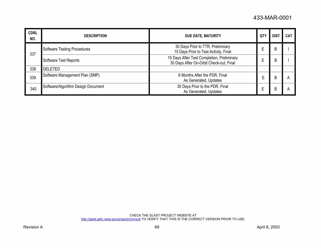
433-MAR-0001
CHECK THE GLAST PROJECT WEBSITE AT http://glast.gsfc.nasa.gov/project/cm/mcdl TO VERIFY THAT THIS IS THE CORRECT VERSION PRIOR TO USE.
Revision A 69 April 8, 2003
CDRL NO.
DESCRIPTION DUE DATE, MATURITY QTY DIST CAT
Software Testing Procedures 30 Days Prior to TTR, Preliminary 15 Days Prior to Test Activity, Final E B I
337 Software Test Reports 15 Days After Test Completion, Preliminary
30 Days After On-Orbit Check-out, Final E B I
338 DELETED
339 Software Management Plan (SMP) 6 Months After the PDR, Final As Generated, Updates E B A
340 Software/Algorithm Design Document 30 Days Prior to the PDR, Final As Generated, Updates E B A

433-MAR-0001
CHECK THE GLAST PROJECT WEBSITE AT
http://glast.gsfc.nasa.gov/project/cm/mcdl TO VERIFY THAT THIS IS THE CORRECT VERSION PRIOR TO USE. Revision A 70 April 8, 2003
PERFORMANCE ASSURANCE IMPLEMENTATION PLAN Title:
Performance Assurance Implementation Plan
CDRL No.: 301
Reference:
MAR Section 1.1 Use:
Detail the developer’s system safety and mission assurance program for their GLAST instrument. Related Documents
None Place/time/purpose of delivery:
Delivery is due to GSFC 90 days after contract signing for approval. Any subsequent revisions to PAIP must be submitted to GSFC for approval.
Preparation Information: The Performance Assurance Implementation Plan will include the details of the developer’s plans for implementing the following program:
a) System Safety (May be a separate document.) b) Technical Review c) Design Verification d) Electronic Packaging and Processes e) Parts (May be a separate document.) f) Materials, Processes, and Lubrication (May be a separate document.) g) Reliability h) Quality Assurance i) Contamination Control j) Software Assurance k) Ground Data Systems Assurance l) Risk Management

433-MAR-0001
CHECK THE GLAST PROJECT WEBSITE AT
http://glast.gsfc.nasa.gov/project/cm/mcdl TO VERIFY THAT THIS IS THE CORRECT VERSION PRIOR TO USE. Revision A 71 April 8, 2003
SYSTEM SAFETY PROGRAM PLAN Title:
System Safety Program Plan
CDRL No.: 303
Reference:
MAR Section 2.2 Use:
This plan describes in detail the tasks and activities of system safety management and engineering required to identify, evaluate, eliminate, and control hazards or reduce the associated risk to a level acceptable to Range Safety throughout the system life cycle. The approved plan shall account for all contractually required tasks and responsibilities on an item-by-item basis.
Related Documents: EWR 127-1
Place/Time/Purpose of Delivery:
Deliver to GSFC with, or as part of, the Performance Assurance Implementation Plan for approval. Any subsequent revisions must be approved by GSFC.
Preparation Information:
Refer to Appendix 1B of EWR 127-1 for preparation directions.

433-MAR-0001
CHECK THE GLAST PROJECT WEBSITE AT
http://glast.gsfc.nasa.gov/project/cm/mcdl TO VERIFY THAT THIS IS THE CORRECT VERSION PRIOR TO USE. Revision A 72 April 8, 2003
PRELIMINARY HAZARD ANALYSIS (PHA) Title:
Preliminary Hazard Analysis (PHA)
CDRL No.: 304
Reference:
MAR Section 2.2 Use:
Used to identify safety critical areas, provide an initial assessment of hazards, and identify requisite hazard controls and follow-on actions. The analysis will result in an initial risk assessment of the system.
Related Documents: EWR 127-1
NASA GB 1740.13.96, NASA Guidebook for Safety Critical Software Place/Time/Purpose of Delivery:
The first delivery will be at the PDR for GSFC approval. An update will be due at CDR for GSFC approval. Preparation Information:
Refer to Appendix 1B of EWR 127-1 for guidance on the performance of a PHA.

433-MAR-0001
CHECK THE GLAST PROJECT WEBSITE AT
http://glast.gsfc.nasa.gov/project/cm/mcdl TO VERIFY THAT THIS IS THE CORRECT VERSION PRIOR TO USE. Revision A 73 April 8, 2003
SAFETY NONCOMPLIANCE REPORTS Title:
Safety Noncompliance Reports
CDRL No.: 305
Reference:
MAR Section 2.2 Use:
Used to document the inability to meet program requirements, or the ability to meet equivalent though not exact, program requirements.
Related Documents: EWR 127-1
Place/Time/Purpose of Delivery:
As required for GSFC approval. Preparation Information:
Refer to Appendix 1C of EWR 127-1 for preparation directions.

433-MAR-0001
CHECK THE GLAST PROJECT WEBSITE AT
http://glast.gsfc.nasa.gov/project/cm/mcdl TO VERIFY THAT THIS IS THE CORRECT VERSION PRIOR TO USE. Revision A 74 April 8, 2003
TECHNICAL REVIEWS Title:
Technical Reviews
CDRL No.: 306
Reference:
MAR Section 3 Use:
Provide review material and hand-outs for technical reviews which review team members will need to read prior to the review. Provide review minutes and action items after technical reviews.
Related Documents: None
Place/Time/Purpose of Delivery: Provide review materials/hand-outs 7 work days prior to each GSFC- chaired/co-chaired technical review for information. This will include the such reviews listed in LAT MAR Section 3. Provide minutes and action items from each technical review (peer or GSFC-chaired/co-chaired) within 10 work days following each review for GSFC review.
Provide responses to Government action items/requests for information (per the schedule established at/for the review) for GSFC approval.
Preparation Information:
Prior to each GSFC-chaired/co-chaired technical review, provide an electronic copy of technical review material including vu-graphs. Documentation may be made available via a website. Material shall include risk and safety status as of the date of the particular technical review.
Following each peer review, provide meeting minutes and action items. Material may be provided via hard copy, electronic copy, or website. Following each GSFC-chaired/co-chaired technical review, provide meeting minutes, as needed or as agreed upon with the GLAST Project Office, to supplement/complement the GSFC chair’s/co-chair’s minutes. This may include splinter meeting minutes. Additionally, after each GSFC-chaired/co-chaired technical review, provide any pertinent action items authored by the developer and/or their collaborators during the meeting or as a result of the meeting.
Provide responses to Government actions items/requests for information/action via the format requested at each review: electronic, hard copy or web-based.

433-MAR-0001
CHECK THE GLAST PROJECT WEBSITE AT
http://glast.gsfc.nasa.gov/project/cm/mcdl TO VERIFY THAT THIS IS THE CORRECT VERSION PRIOR TO USE. Revision A 75 April 8, 2003
INSTRUMENT PERFORMANCE VERIFICATION PLAN Title:
Instrument Performance Verification Plan
CDRL No.: 307
Reference:
MAR Section 4.2.1 Use:
Provides the overall approach for accomplishing the verification program. Defines the specific tests, analyses, calibrations, alignments, etc. that will demonstrate that the hardware complies with the mission requirements.
Related Documents
None Place/Time/Purpose of Delivery:
Provide a preliminary draft of the Instrument Performance Verification Plan 20 work days prior to the PDR for GSFC review. The final draft will be due 20 work days prior to the CDR for GSFC approval. Updates will be provided as required for GSFC approval. Additionally, prepare instrumentation plans for all structural subsystem tests prior to the CDR and submit them to GSFC for approval at least 30 days prior to implementation. Updates will be provided as required for GSFC approval.
Preparation Information: Describes the approach (test, analysis, etc.) that will be utilized to verify that the hardware/software complies with mission requirements. If verification relies on tests or analyses at other level of assemblies, describe the relationships.
A section of the plan will be an Instrument Performance Verification Matrix summarizing the flow-down of system specification requirements that stipulates how each requirement will be verified, and summarizes compliance/non-compliance with requirements. It will show each specification requirement, the reference source (to the specific paragraph or line item), the method of compliance, applicable procedure references, report reference numbers, etc. The Instrument Performance Verification Matrix may be made a separate document.
The Instrument Performance Verification Plan will include a section describing the environmental verification program. This will include level of assembly, configuration of item, objectives, facilities, instrumentation, safety considerations, contamination control, test phases and profiles, appropriate functional operations, personnel responsibilities, and requirements for procedures and reports. For each analysis activity, include objectives, a description of the mathematical model, assumptions on which the model will be based, required output, criteria for assessing the acceptability of the results, interaction with related test activity, and requirements for reports. Provide for an operational methodology for controlling, documenting, and approving activities not part of an approved procedure. Plan controls that prevent accidents that could damage or contaminate hardware or facilities, or cause personal injury. The controls will include real-time decision-making mechanisms for continuation or suspension of testing after malfunction, and a method for determining retest requirements, including the assessment of the validity of previous tests. Include a test matrix that summarizes all tests to be performed on each component, each subsystem, and the payload. Include tests on engineering models performed to satisfy qualification requirements. Define pass/fail criteria. The Environmental Test Plan section will include an Environmental Test Matrix which summarizes all environmental tests that will be performed showing the test and the level of assembly. Tests on development/engineering models performed to satisfy qualification requirements will be included in this matrix. The Environmental Verification Plan may be made a separate document rather than be a part of the Instrument Performance Verification Plan
As an adjunct to the environmental verification program, an Environmental Test Tracking Matrix summarizing all tests performed and showing the test and the level of assembly will be maintained.
The Instrument Performance Verification Plan will include an Environmental Verification Specification section that stipulates the specific environmental parameters used in each test or analysis required by the verification plan. Contains the specific test and analytical parameters associated with each of the tests and analyses required by the Verification Plan. Payload peculiarities and interactions with the launch vehicle will be considered when defining quantitative environmental parameters under which the hardware elements must meet their performance requirements. The Environmental Verification Specification may be a separate

433-MAR-0001
CHECK THE GLAST PROJECT WEBSITE AT
http://glast.gsfc.nasa.gov/project/cm/mcdl TO VERIFY THAT THIS IS THE CORRECT VERSION PRIOR TO USE. Revision A 76 April 8, 2003
document or it may be included as part of the Instrument Performance Verification Plan.
At a minimum, the subsystem test instrumentation plans will:
a. Address the practicality of locating instrumentation on the LAT hardware and the suitability of instrument locations for gathering data to correlate structural models
b. Identify test cable routing requirements c. Ensure compatibility of test data taken during the different tests d. Identify test instruments that will be removed before flight and those that will be flown with the instrument.

433-MAR-0001
CHECK THE GLAST PROJECT WEBSITE AT
http://glast.gsfc.nasa.gov/project/cm/mcdl TO VERIFY THAT THIS IS THE CORRECT VERSION PRIOR TO USE. Revision A 77 April 8, 2003
PARTS CONTROL PLAN (PCP) Title:
Parts Control Plan (PCP)
CDRL No.: 308
Reference:
MAR Sections 6.1, 6.2.1, 6.2.2, 6.2.3, & 6.2.6 Use:
Description of developer’s approach and methodology for implementation of the Parts Control Program. Related Documents
Parts Identification List (PIL) Place/Time/Purpose of Delivery:
The PCP will be developed and delivered for GSFC review with, or incorporated into, the developer’s Performance Assurance Implementation Plan. It will be delivered for GSFC approval. Any subsequent revisions must be delivered to GSFC for approval.
Preparation Information: The PCP will be prepared and will address all EEE parts program requirements. The PCP will contain, as a minimum, detailed discussions of the following:
a. The developer’s plan or approach for conforming to the EEE parts requirements.
b. The developer’s parts control organization, identifying key individuals, and specific responsibilities.
c. Detailed Parts Control Board (PCB) procedures, to include PCB membership, designation of Chairperson, responsibilities, review and approval procedures, meeting schedules and method of notification, meeting minutes, etc.
d. Parts tracking methods and approach, including tools to be used such as databases, reports, PIL, etc. Describe system for identifying and tracking parts approval status.
e. Parts procurement, processing and testing methodology and strategies. Identify internal operating procedures to be used for incoming inspections, screening, qualification testing, derating, testing of parts pulled from stores, Destructive Physical Analysis, radiation assessments, etc.

433-MAR-0001
CHECK THE GLAST PROJECT WEBSITE AT
http://glast.gsfc.nasa.gov/project/cm/mcdl TO VERIFY THAT THIS IS THE CORRECT VERSION PRIOR TO USE. Revision A 78 April 8, 2003
PARTS CONTROL BOARD (PCB) AND MECHANICAL PART REVIEW BOARD (MPRB) REPORTS Title:
Parts Control Board (PCB) and Mechanical Part Review Board (MPRB) Reports
CDRL No.: 309
Reference:
MAR Sections 6.2.1.1 Use:
Document all PCB and MPRB meeting minutes Related Documents
Parts Control Plan (PCP) Place/Time/Purpose of Delivery:
PCB/MPRB reports will be submitted to GSFC for review within five workdays after each PCB or MPRB meeting. Preparation Information: Actions and recommendations from reviews and discussions of all issues effecting EEE parts (e.g., alert findings, DPA results, failure analysis results, qualification basis, screening requirements, etc.) shall be recorded in the PCB reports. Additionally, actions and recommendations from reviews and discussions affecting GLAST materials, processes and lubricants will be recorded in the MPRB reports.

433-MAR-0001
CHECK THE GLAST PROJECT WEBSITE AT
http://glast.gsfc.nasa.gov/project/cm/mcdl TO VERIFY THAT THIS IS THE CORRECT VERSION PRIOR TO USE. Revision A 79 April 8, 2003
PARTS IDENTIFICATION LIST (PIL)/PROGRAM PARTS LIST (PPL)/AS BUILT PROGRAM PARTS LIST (ABPL) Title:
Parts Identification List (PIL)/Program Parts List (PPL)/As Built Parts List (ABPL)
CDRL No.: 310
Reference:
MAR Sections 6.3 & 6.3.2 Use:
Listing of all EEE parts intended for use in spaceflight hardware Related Documents
Parts Control Plan (PCP) Place/Time/Purpose of Delivery:
The initial parts list delivery will be due to GSFC for approval 30 days prior to the PDR. Subsequent revisions (with all changes clearly noted on a hard copy) will be delivered to GSFC in a timely manner for approval with an updated revision due 30 days prior to the CDR and as mandated by list changes.. The As Built Parts List [ABPL] will be developed from this document/database and will be submitted to GSFC for review 60 days prior to delivery of the end item to the spacecraft contractor and/or the Government.
Preparation Information: The PIL/PPL/ABPL will be prepared and maintained throughout the life of the project. The PIL/PPL/ABPL will be compiled by instrument or instrument component and will include the following information, as a minimum:
a. Part name b. Part number c. Manufacturer d. Manufacturer’s generic part number e. Procurement specification
Any format may be used provided the required information is included. All submissions to GSFC will be provided in an electronic spreadsheet format. A hard copy will accompany the electronic version. Any changes from the last revision shall be clearly noted on the hard copy. (That is, updates to PIL will identify changes from the previous submission.) Note: The As-Built Parts List (ABPL) will include the following information in addition to the above list:
a. Lot date code b. Quantities c. Parts use location to the sub-assembly level

433-MAR-0001
CHECK THE GLAST PROJECT WEBSITE AT
http://glast.gsfc.nasa.gov/project/cm/mcdl TO VERIFY THAT THIS IS THE CORRECT VERSION PRIOR TO USE. Revision A 80 April 8, 2003
ALERT/ADVISORY DISPOSITION AND PREPARATION Title:
Alert/Advisory Disposition and Preparation
CDRL No.: 311
Reference:
MAR Sections 6.4 Use:
Review and the disposition of GIDEP Alerts and NASA Alerts and Advisories which are provided to the Developer by GSFC or another source. Prepare, or assist GSFC in preparing, Alerts/Advisories based on part anomalies/concerns resulting from the Developer’s own experience.
Related Documents
Parts Control Plan (PCP) Place/Time/Purpose of Delivery:
Respond to GSFC within 25 calendar days of receipt of Alert/Advisory. Alert/advisory impacts, if any, should be discussed at technical reviews and PCB meetings. This information will be provided for GSFC information; however, GSFC must concur with the developer that all flight hardware is flightworthy. Developer-prepared alerts/advisories will be prepared within 60 days in coordination with GSFC, as needed.
Preparation Information: Developer will provide an impact statement to GSFC for each Alert or Advisory reviewed. When a negative impact exists, the developer will provide a narrative plan of action and an implementation date within the 25 calendar days listed above. The developer will notify GSFC within 2 workdays of discovering a suspect part/lot. Information will be shared with GSFC so that GSFC can assist the developer in preparing an Alert/Advisory, if necessary.

433-MAR-0001
CHECK THE GLAST PROJECT WEBSITE AT
http://glast.gsfc.nasa.gov/project/cm/mcdl TO VERIFY THAT THIS IS THE CORRECT VERSION PRIOR TO USE. Revision A 81 April 8, 2003
MATERIALS, PROCESSES AND LUBRICATION ASSURANCE PLAN Title:
Materials, Processes and Lubrication Assurance Plan
CDRL No.: 312
Reference:
MAR Section 7.1 Use:
Documents the developer’s materials engineering and assurance program Related Documents:
None
Place/Time/Purpose of Delivery:
A Plan will be developed and delivered for GSFC review with, or incorporated into, the developer’s Performance Assurance Implementation Plan. The Plan will be delivered to GSFC for approval. Any subsequent changes/revisions must be delivered to GSFC for approval.
Preparation Information: The Materials, Processes and Lubrication Assurance Plan will contain:
a. Table of contents. b. Organization of materials group, project management group and connecting organization. c. Authority and methods of material and lubrication assurance control of hardware drawing signatures d. Failure analysis participation e. Materials review board participation f. Technical skill mix and laboratory capabilities g. The responsibility of materials and lubrication engineering in the design, drawing and process control in the engineering,
fabrication and testing control system utilized by the developer. h. Limited shelf-life materials control program.

433-MAR-0001
CHECK THE GLAST PROJECT WEBSITE AT
http://glast.gsfc.nasa.gov/project/cm/mcdl TO VERIFY THAT THIS IS THE CORRECT VERSION PRIOR TO USE. Revision A 82 April 8, 2003
MATERIALS USAGE AGREEMENT Title:
Materials Usage Agreement
CDRL No.: 313
Reference:
MAR Sections 7.2.1, 7.2.2, 7.2.2.1, 7.2.5.2 and 7.2.6 Use:
For usage evaluation and approval of non-compliant materials or lubrication usage. Related Documents:
GSFC -SPEC-522, GSFC-HDBK-527, NHB 1700.7, GMI 1700.3, NASA-STD-6001
Place/Time/Purpose of Delivery: Provide to the GSFC Project Office, with the materials usage lists, 30 days prior to the PDR for GSFC approval. Additionally, updates, as required, must be provided to GSFC 30 days before the CDR for approval and 30 days before hardware acceptance for approval. Preparation Information: A Materials Usage Agreement (MUA) will be provided, for each non-compliant off-the-shelf-hardware material usage, non-compliant polymeric material outgassing, flammability or toxicity usage and non-compliant inorganic material stress corrosion cracking usage. The MUA will be provided on a Material Usage Agreement form, a contractor’s equivalent form, or the contractor’s electronically transmitted form. The GSFC MUA form is Figure 7-1 in this document. The MUA form requires the minimum following information: MSFC 527 material rating, usage agreement number, page number, drawing numbers, part or drawing name, assembly, material name and specification, manufacturer and trade name, use thickness, weight, exposed area, pressure, temperature, exposed media, application, rationale for safe and successful flight, originator’s name, project manager’s name and date. The off-the-shelf-hardware usage must identify the measures to be used to ensure the acceptability of the hardware such as hermetic sealing, material changes to known compliant materials, vacuum bake-out to the error budget requirements listed in the contamination control plan.

433-MAR-0001
CHECK THE GLAST PROJECT WEBSITE AT
http://glast.gsfc.nasa.gov/project/cm/mcdl TO VERIFY THAT THIS IS THE CORRECT VERSION PRIOR TO USE. Revision A 83 April 8, 2003
POLYMERIC MATERIALS AND COMPOSITES USAGE LIST Title:
Polymeric Materials and Composites Usage List
CDRL No.: 314
Reference: MAR Section 7.2.5
Use: For usage evaluation and approval of all polymeric and composite materials applications.
Related Documents: NASA RP-1124, ASTM E 595, MSFC-HDBK-527, NHB 1700.7, EWR 127.1, GMI 1700.3, NASA-STD-6001
Place/Time/Purpose of Delivery: Provide to the GSFC Project Office 30 days before PDR for review. Additionally, the current list must be provided to GSFC 30 days before the CDR for approval and 30 days before hardware acceptance for approval.
Preparation Information: The developer will provide the information requested via the GSFC polymeric materials and composites usage list form, an equivalent developer’s form, or an equivalent electronic format. The GSFC form is Figure 7-3 of this document. The polymeric materials and composites usage list form requires, as a minimum, the following information: spacecraft, subsystem or instrument name, GSFC technical officer, contractor, address, prepared by, phone number, date of preparation, GSFC materials evaluator, evaluator’s phone number, date received, date evaluated, item number (1), material identification (2), mix formula (3), cure (4), amount code, expected environment (5), outgassing values and reason for selection (6). (Notes 1 through 6 are listed below.)
1. List all polymeric materials and composites applications utilized in the system except lubricants which should be listed on polymeric and composite materials usage list.
2. Give the name of the material, identifying number and manufacturer. For example: Epoxy, Epon 828, E. V. Roberts and Associates
3. Provide proportions and name of resin, hardener (catalyst), filler, etc. For example: 828/V140/Silflake 135 as 5/5/38 by weight 4. Provide cure cycle details. For example: 8 hours. at room temperature plus 2 hours. at 150C 5. Provide the details of the environment that the material will experience as a finished spacecraft component, both in ground test
and in space. List all materials with the same environment in a group. For example: Thermal vacuum-20C/+60C, 2 weeks, 10E-5 torr, ultraviolet radiation (UV); Storage: Up to 1 year at room temperature; Space: -10C/+20C, 2 years, 150 mile altitude, UV, electron, proton, atomic oxygen
6. Provide any special reason why the materials was selected. If for a particular property, please give the property. For example: Cost, availability, room temperature curing, or low thermal expansion.

433-MAR-0001
CHECK THE GLAST PROJECT WEBSITE AT
http://glast.gsfc.nasa.gov/project/cm/mcdl TO VERIFY THAT THIS IS THE CORRECT VERSION PRIOR TO USE. Revision A 84 April 8, 2003
INORGANIC MATERIALS AND COMPOSITES USAGE LIST Title:
Inorganic Materials and Composites Usage List
CDRL No.: 315
Reference:
MAR Section 7.2.6 Use:
For usage evaluation and approval of all metal, ceramic, and metal/ceramic composite material applications.
Related Documents: MSFC-HDBK-527, NHB 1700.7, MSFC-SPEC-522
Place/Time/Purpose of Delivery: Provide to the GSFC Project Office 30 days before PDR for review. Additionally, the current list must be provided to GSFC 30 days before the CDR for approval and 30 days before hardware acceptance for approval.
Preparation Information: The hardware provider will provide the information requested via the GSFC inorganic materials and composites usage list form, an equivalent developer’s form, or an equivalent electronic format. The GSFC form is Figure 7-4 of this document. The inorganic materials and composite usage list form requires, as a minimum, the following information: spacecraft, subsystem or instrument name, GSFC technical officer, contractor, contractor address, prepared by, phone number, date of preparation, GSFC materials evaluator, evaluator’s phone number, date received, item number, materials identification (1), condition (2), application or usage (3), expected environment (4), stress corrosion cracking table number, MUA number and NDE method. (Notes 1 through 4 are listed below.) List all inorganic materials (metals, ceramics, glasses, liquids and metal/ceramic composites) except bearing and lubrication materials which should be listed on Form 18-59C. 1. Give materials name and identifying number manufacturer. For example: Aluminum 6061-T6; Electroless nickel plate, Enplate
Ni 410, Enthone, Inc.; Fused silica, Corning 7940, Corning Class Works 2. Give details of the finished condition of the material, heat treatment designation (hardness or strength), surface finish and coating,
cold worked state, welding, brazing, etc. For example: Heat treated to Rockwell C 60 hardness, gold electroplated, brazed; surface coated with vapor deposited aluminum and magnesium fluoride; cold worked to full hard condition, TIG welded and electroless nickel plated.
3. Give details of where on the spacecraft the material will be used (component) and its function. For example: Electronics box structure in attitude control system, not hermetically sealed.
4. Give the details of the environment that the material will experience as a finished spacecraft component, both during ground testing and in space. Exclude vibration environment. List all materials with the same environment in a group. For example: Thermal vacuum - -20C/+60C, 2 weeks, 10E-5 torr, Ultraviolet radiation (UV); Storage - Up to 1 year at room temperature; Space - -10C/+20C, 2 years, 150 miles altitude, UV, electron, proton, Atomic Oxygen.

433-MAR-0001
CHECK THE GLAST PROJECT WEBSITE AT
http://glast.gsfc.nasa.gov/project/cm/mcdl TO VERIFY THAT THIS IS THE CORRECT VERSION PRIOR TO USE. Revision A 85 April 8, 2003
LUBRICATION USAGE LIST
Title: Lubrication Usage List
CDRL No.: 316
Reference:
MAR Section 7.2.7 Use:
For evaluation and approval of all lubricant usage and applications. Related Documents:
None Place/Time/Purpose of Delivery:
Provide to the GSFC Project Office 30 days before PDR for review. Additionally, the current list must be provided to GSFC 30 days before the CDR for approval and 30 days before hardware acceptance for approval.
Preparation Information: The hardware developer will provide the information requested via the GSFC lubricant usage list form, an equivalent developer’s form, or an equivalent electronic format. The GSFC form is Figure 7-5 of this document. The lubricant usage list form requires, as the minimum, the following information: spacecraft, subsystem or instrument name, GSFC technical officer, contractor, contractor address, prepared by, phone number, date of preparation, GSFC materials evaluator, evaluator’s phone number, date received, item number, component type, size, material (1); component manufacturer and manufacturer identification; proposed lubrication system and amount of lubrication; type and number of wear cycles (2); speed, temperature and atmosphere of operation (3); type and magnitude of loads (4) and other details (5). (Notes 1 through 5 are listed below.) 1. Ball bearing (BB), Sleeve bearing (SB), Gear (G), Sliding surfaces (SS), or Sliding electrical contacts (SEC). Give generic
identification of materials used for the component. For example: 440C steel, PTFE.
2. Continuous unidirectional rotation (CUR), continuous oscillation (CO), intermittent rotation (IR), intermittent oscillation (IO), small angle (less than 30o) oscillation (SAM), large angle (greater than 30o) oscillation (LAM), continuous sliding (CS), or intermittent sliding (IS). State the number of wear cycles: 1 to 1E2 (“A”), 1E2 to 1E4 (“B”), 1E4 to 1E6 (“C”), or greater than 1E6 (“D”).
3. State speed: as revolution per min. (RPM), oscillations per min. (OPM), variable speed (VS), or sliding speed in cm. per minute (CPM). State operational temperature range atmosphere as: vacuum, air, gas sealed or unsealed and pressure.
4. Type of loads: axial, radial, tangential (gear load). Give magnitude of load.
5. For ball bearings, give type and material of ball cage, number of shields, and type of ball groove surface finishes. For gears, give surface treatment and hardness. For sleeve bearings, give the bore diameter and width. Provide the torque and torque margins.

433-MAR-0001
CHECK THE GLAST PROJECT WEBSITE AT
http://glast.gsfc.nasa.gov/project/cm/mcdl TO VERIFY THAT THIS IS THE CORRECT VERSION PRIOR TO USE. Revision A 86 April 8, 2003
MATERIAL PROCESS UTILIZATION LIST Title:
Material Process Utilization List
CDRL No.: 317
Reference:
MAR Section 7.3 Use:
For usage evaluation and approval of all material processes that are used to fabricate, clean, store, integrate, and test the space flight hardware.
Related Documents:
None Place/Time/Purpose of Delivery:
Provide to the GSFC Project Office 30 days before PDR for review. Additionally, the current list must be provided to GSFC 30 days before the CDR for approval and 30 days before hardware acceptance for approval. A copy of any process will be submitted to the GSFC Project Office upon request.
Preparation Information: The developer will provide the information requested via the GSFC material process utilization list form, an equivalent developer’s form, or an equivalent electronic format. The GSFC form is Figure 7-6 of this document. The material process utilization list requires, as a minimum, the following information: spacecraft, subsystem or instrument name, GSFC technical officer, contractor, address, prepared by, phone number, date of preparation, GSFC materials evaluator, evaluator’s phone number, date received, date evaluated, item number, process type (1), contractor specification number (2), Military, ASTM, Federal or other specification number, description of material processed, (3) and spacecraft/instrument application (4). (Notes 1 through 4 are listed below.)
1. Give the generic name of the process. For example: anodizing (sulfuric acid) 2. If the process is proprietary, please state so. 3. Identify the type and condition of the material subjected to the process. For example: 6061-T6 4. Identify the component or structure for which the materials are being processed. For example: Antenna dish.
All welding and brazing of all flight hardware, including repairs, shall be performed by certified operators in accordance with the requirements of the appropriate industry or government standards. A copy of the procedure qualification record (PQR) and a current copy of the operator qualification test record made available for review upon request.

433-MAR-0001
CHECK THE GLAST PROJECT WEBSITE AT
http://glast.gsfc.nasa.gov/project/cm/mcdl TO VERIFY THAT THIS IS THE CORRECT VERSION PRIOR TO USE. Revision A 87 April 8, 2003
FAILURE MODE AND EFFECTS ANALYSIS (FMEA) AND CRITICAL ITEMS LIST (CIL) Title:
Failure Mode and Effects Analysis (FMEA) and Critical Items List (CIL)
CDRL No.: 318
Reference:
MAR Section 8.2.1 Use:
Reliability analysis to evaluate the design relative to requirements, identify single point failures, and identify hazards. Related Documents
a. Procedures for Performing an FMEA, S-302-720, b. CR 5320.9, Payload and Experiment Failure Mode Effects Analysis and Critical Items List Ground Rules, MSFC. c. MIL-STD 1629A, Procedures for Performing an FMECA, DoD.
Place/Time/Purpose of Delivery: Provide a preliminary draft to the GSFC Project Office 30 days before PDR for review. Additionally, the final version must be provided to GSFC 30 days before the CDR for review. Updates, as required, will be delivered to GSFC for review. Changes from previous versions should be clearly noted on the updates and final versions. Preparation Information: The FMEA report will document the study including the approach, methodologies, results, conclusions, and recommendations. The report will include objectives, level of the analysis, ground rules, functional description, functional block diagrams, reliability block diagrams, bounds of equipment analyzed, reference to data sources used, identification of problem areas, single-point failures, recommended corrective action, and work sheets as appropriate for the specific analyses being performed. The CIL will include item identification, cross-reference to FMEA line items, and retention rationale. Appropriate retention rationale may include design features, historical performance, acceptance testing, manufacturing product assurance, elimination of undesirable failure modes, and failure detection methods.

433-MAR-0001
CHECK THE GLAST PROJECT WEBSITE AT
http://glast.gsfc.nasa.gov/project/cm/mcdl TO VERIFY THAT THIS IS THE CORRECT VERSION PRIOR TO USE. Revision A 88 April 8, 2003
LIMITED-LIFE ITEMS Title:
Limited-Life Items
CDRL No.: 319
Reference:
MAR Section 8.4 Use:
Defines and tracks the selection, use, and wear of limited-life items and their impact on mission operations. Related Documents
None Place/Time/Purpose of Delivery:
Provide to the GSFC Project Office 30 days before PDR for review. Additionally, the current list must be provided to GSFC 30 days before the CDR for approval. Updates must be submitted to GSFC for approval as they are released.
Preparation Information: List life-limited items and their impact on mission parameters. Define expected life, required life, duty cycles, and rationale for selecting and using the items. Include selected structures, thermal control surfaces, solar arrays, and electromechanical mechanisms. Atomic oxygen, solar radiation, shelf-life, extreme temperatures, thermal cycling, wear and fatigue are used to identify limited-life thermal control surfaces and structural items. When aging, wear, fatigue and lubricant degradation limit their life; include batteries, compressors, seals, bearings, valves, tape recorders, momentum wheels, gyros, actuators and scan devices. Assign responsibilities and describe managerial and reporting activities.

433-MAR-0001
CHECK THE GLAST PROJECT WEBSITE AT
http://glast.gsfc.nasa.gov/project/cm/mcdl TO VERIFY THAT THIS IS THE CORRECT VERSION PRIOR TO USE. Revision A 89 April 8, 2003
QUALITY MANUAL Title:
Quality Manual
CDRL No.: 320
Reference:
MAR Section 9.0 Use:
Documents the developer's quality management system. Related Documents:
ANSI/ASQC Q9001-1994, Section 4.2.1 Place/Time/Purpose of Delivery:
Provide developer’s Quality Manual and any updates to GSFC Project Office for review within 90 days of contract signing. The documentation may be available by electronic copy, by hard copy, or via the web.
Preparation Information: Prepare a Quality Manual addressing all applicable requirements (from the 20 total elements) of ANSI/ASQC Q9001-1994. Refer to ISO 10013 for further guidelines on preparation of a quality manual.
The Quality Manual will comply with Q9001 and it will contain:
a. The title, approval page, scope, and the field of application b. Table of contents c. Introductory pages about the organization concerned and the manual itself d. The quality policy and objectives of the organization e. The description of the organization, responsibilities, and authorities including the organization responsible for the EEE parts,
materials, reliability, safety and test requirements implementation f. A description of the elements of the quality system, developer policy regarding each element and developer implementation
procedure for each Q9001 element or reference(s) to approved quality system procedures. System level procedures will address the implementation of all requirements cited in this document.
g. A definitions section, if appropriate h. An appendix for supportive data, if appropriate.
Quality Manual issuance and change will be implemented by a controlled process. The Quality Manual will be maintained/updated by the developer throughout the life of the contract.

433-MAR-0001
CHECK THE GLAST PROJECT WEBSITE AT
http://glast.gsfc.nasa.gov/project/cm/mcdl TO VERIFY THAT THIS IS THE CORRECT VERSION PRIOR TO USE. Revision A 90 April 8, 2003
NONCONFORMANCE REPORTS (NCR’S) Title:
Nonconformance Reports
CDRL No.: 321
Reference:
MAR Section 9.1.2 Use:
To report failures promptly for determination of cause and corrective action. Related Documents:
GPG 5340.2, GPG 1710.1, GPG 4520.2, GPG 5100.1, GPG 5900.1, 302-PG-1410.2.1 Place/Time/Purpose of Delivery:
a. Provide for information to the GSFC Project Office within 24 hours of each occurrence; b. Provide updates for review to the GSFC Project Office at the completion of analysis and assignment of corrective action; c. Provide to GSFC Project Office for approval within 3 work days after developer closure.
Reports may be delivered to GSFC as electronic copies or they may be made available to GSFC via a developer website. If a website is utilized, GSFC will be notified within 8 work hours that a report or new information has been posted. Preparation Information: Reporting of failures will begin with the first power application at the major component, subsystem, or instrument level or the first operation of a mechanical item. It will continue through formal acceptance by the GSFC Project Office and the post-launch operations, commensurate with developer presence and responsibility at GSFC and launch site operations. All failures at GSFC will be documented via the GSFC NCR/CA database. Non-GSFC developers, need to provide copies of failure, problem, nonconformance, and/or anomaly reports per the delivery schedule listed above. The developer’s forms may be used but should include information equivalent to that stored in the GSFC NCR/CA database. The developer will provide the GSFC Project Office with any/all Material Review Board (MRB) and Failure Review Board (FRB) documentation including minutes and reports.

433-MAR-0001
CHECK THE GLAST PROJECT WEBSITE AT
http://glast.gsfc.nasa.gov/project/cm/mcdl TO VERIFY THAT THIS IS THE CORRECT VERSION PRIOR TO USE. Revision A 91 April 8, 2003
CONTAMINATION CONTROL PLAN Title:
Contamination Control Plan
CDRL No.: 322
Reference:
MAR Sections 10.1 & 10.2 Use:
To establish contamination allowances and methods for controlling contamination Related Documents:
None Place/Time/Purpose of Delivery:
Provide a preliminary draft to the Project Office 30 days before PDR for GSFC review. Provide a final draft to the Project Office 30 days before the CDR for approval.
Preparation Information: Data on material properties, design features, test data, system tolerance of degraded performance, and methods to prevent degradation will be provided to permit independent evaluation of contamination hazards. The items should be included in the plan for delivery: The CCP should cover:
1. Materials
a. Outgassing as a function of temperature and time b. The nature of outgassing chemistry c. Areas, weight, location, and view factors of critical surfaces
2. Venting: size, location and relation to external surfaces. 3. The thermal vacuum test contamination monitoring plan including vacuum test data, QCM rates and location, temperature and
pressure data, system temperature profile, and shroud temperature. 4. On orbit spacecraft and instrument performance as affected by contamination deposits including
a. Contamination effect monitoring b. Methods to prevent and recover from contamination in orbit c. How to evaluate in orbit degradation d. Photopolymerization of outgassing products on critical surfaces e. Space debris risks and protection f. Atomic oxygen erosion and re-deposition
5. MOLEFLUX or equivalent analysis of contamination impact on the satellite’s on-orbit performance. 6. In orbit contamination impact from other sources such as adjacent instruments.

433-MAR-0001
CHECK THE GLAST PROJECT WEBSITE AT
http://glast.gsfc.nasa.gov/project/cm/mcdl TO VERIFY THAT THIS IS THE CORRECT VERSION PRIOR TO USE. Revision A 92 April 8, 2003
RISK MANAGEMENT PLAN Title:
Risk Management Plan
CDRL No.: 323
Reference:
MAR Section 12.1 Use:
To document the developer's approach to implementing a risk management program.
Related Documents:
NPG 7120.5A, Section 4.2 Website http://satc.gsfc.nasa.gov/crm/ for Risk Management Plan templates and sample plans
Place/Time/Purpose of Delivery:
Deliver to GSFC with, or as part of, the Performance Assurance Implementation Plan for approval. Any subsequent revisions must be approved by GSFC.
Preparation Information: Section 1. Introduction
1.1 Purpose and Scope 1.2 Assumptions, Constraints, and Policies 1.3 Related Documents and Standards
Section 2. Overview of Risk Management Practice 2.1 Overview 2.2 Process and Data Flows 2.3 Project Management Integration (optional) Section 3. Organization 3.1 Organizational Chart 3.2 Project Communication and Responsibilities 3.3 AA Program Responsibilities 3.4 Contractor Responsibilities Section 4. Practice Details 4.1 Establishing Baselines and Reestablishing Baselines 4.2 Identifying Risks 4.3 Analyzing Risks 4.3.1 Criteria for Evaluating Attributes 4.4 Planning Risks 4.5 Tracking and Control of Risks 4.5.1 Collection of Metrics 4.6 Summary of Methods and Tools Section 5. Resources and Schedule of Risk Management Milestones Section 6. Documentation of Risk Information

433-MAR-0001
CHECK THE GLAST PROJECT WEBSITE AT
http://glast.gsfc.nasa.gov/project/cm/mcdl TO VERIFY THAT THIS IS THE CORRECT VERSION PRIOR TO USE. Revision A 93 April 8, 2003
INFORMATION NEEDED TO PREPARE PROBABILISTIC RISK ASSESSMENT (PRA) Title:
Information Needed to Prepare Probabilistic Risk Assessment (PRA)
CDRL No.: 324
Reference:
MAR Section 12.2 Use:
For systems under development, to guide trade-offs between reliability, cost, performance, and other tradable resources. For mature systems, to support decision-making on risk acceptability, and on choices among options for risk reduction.
Related Documents:
None Place/Time/Purpose of Delivery:
As required (for information) for the Government to prepare the PRA prior to PDR and CDR plus updates as required. Preparation Information: The developer and their collaborators will provide the hardware and software information necessary, including parts lists, functional diagrams, and schematics, for the Government to prepare the PRA.

433-MAR-0001
CHECK THE GLAST PROJECT WEBSITE AT
http://glast.gsfc.nasa.gov/project/cm/mcdl TO VERIFY THAT THIS IS THE CORRECT VERSION PRIOR TO USE. Revision A 94 April 8, 2003
INFORMATION NEEDED TO PREPARE FAULT TREE ANALYSIS Title:
Information Needed to Prepare Fault Tree Analysis (FTA)
CDRL No.: 325
Reference:
MAR Section 12.2 Use:
A top down approach for identifying hardware critical failure modes. Related Documents
Nuclear Regulatory Commission publication NUREG-0492, Fault Tree Handbook Place/Time/Purpose of Delivery: As required (for information) for the Government to prepare the FTA prior to PDR and CDR plus updates as required. Preparation Information: The developer and their collaborators will provide the information necessary, including parts lists, functional diagrams, and schematics, for the Government to prepare the FTA.

433-MAR-0001
CHECK THE GLAST PROJECT WEBSITE AT
http://glast.gsfc.nasa.gov/project/cm/mcdl TO VERIFY THAT THIS IS THE CORRECT VERSION PRIOR TO USE. Revision A 95 April 8, 2003
INFORMATION NEEDED TO PREPARE RISK ASSESSMENT Title:
Information Needed to Prepare Risk Assessment
CDRL No.: 326
Reference:
MAR Section 12.3 Use: To determine risks inherent in the project at any one time and identify possible risk mitigation strategies for those risks. Related Documents
None Place/Time/Purpose of Delivery: For information, 30 days after a request for information/data from the Government. Preparation Information: The government will provide a notification to the developer of the scope and/or area of focus of the risk assessment 30 days prior to the assessment. The assessment will focus on products (e.g., hardware and/or software) and/or processes (e.g., design, configuration management, manufacturing, coding, testing). The developer and their collaborators will provide access to the information necessary to support the scope of the assessment.

433-MAR-0001
CHECK THE GLAST PROJECT WEBSITE AT
http://glast.gsfc.nasa.gov/project/cm/mcdl TO VERIFY THAT THIS IS THE CORRECT VERSION PRIOR TO USE. Revision A 96 April 8, 2003
OPERATING AND SUPPORT HAZARD ANALYSIS (O&SHA) Title:
Operating and Support Hazard Analysis (O&SHA)
CDRL No.: 327
Reference:
MAR Section 2.1 Use:
Evaluates activities for hazards or risks introduced into the system by operational and support procedures and evaluates the adequacy of operational and support procedures used to eliminate, control, or abate identified hazards or risks.
Related Documents: EWR 127-1
Place/Time/Purpose of Delivery:
The first delivery is due 30 days prior to the CDR. An updated delivery is due to support final MSPSP delivery to the Range which in turn supports the Mission Approval Safety Review (120 days before launch). GSFC will approval all deliveries/versions.
Preparation Information:
Refer to Appendix 1B of EWR 127-1 for guidance on performance of an O&SHA.

433-MAR-0001
CHECK THE GLAST PROJECT WEBSITE AT
http://glast.gsfc.nasa.gov/project/cm/mcdl TO VERIFY THAT THIS IS THE CORRECT VERSION PRIOR TO USE. Revision A 97 April 8, 2003
HAZARD CONTROL VERIFICATION LOG Title:
Hazard Control Verification Log
CDRL No.: 328
Reference:
MAR Section 2.1 Use:
Used to document the instrument safety assessment such that it reflects how the instrument design demonstrates compliance with the safety requirements.
Related Documents: EWR 127-1
Place/Time/Purpose of Delivery:
Initially generated to document results of hazard analyses and updated as analysis results warrant. It will be made available to Range Safety upon request. Delivery shall support the spacecraft contractor’s MSPSP submittal schedule. (Note: The final MSPSP will be submitted to Range Safety at least 45 calendar days prior to hardware shipment to Range. GSFC will approve all deliveries/versions.
Preparation Information:
Refer to Appendix 1B.1 of EWR 127-1 for preparation directions.

433-MAR-0001
CHECK THE GLAST PROJECT WEBSITE AT
http://glast.gsfc.nasa.gov/project/cm/mcdl TO VERIFY THAT THIS IS THE CORRECT VERSION PRIOR TO USE. Revision A 98 April 8, 2003
SAFETY ASSESSMENT REPORT (SAR) Title:
Safety Assessment
CDRL No.: 329
Reference:
MAR Section 2.1 Use:
The Safety Assessments are used to document a comprehensive evaluation of the mishap risk being assumed prior to the testing or operation of a system. The Ssafety assessments will be provided to the Spacecraft Contractor as an input to their preparation of the Missile System Prelaunch Safety Package (MSPSP), which is one of the media through which missile system prelaunch safety approval is obtained.
Related Documents: EWR 127-1
Place/Time/Purpose of Delivery: SAR delivery shall support the spacecraft contractor’s MSPSP submittal schedule. (Note: The final MSPSP will be submitted to Range Safety at least 45 calendar days prior to hardware shipment to Range. GSFC will approve all deliveries/versions. Preparation Information:
The Safety Assessment swill identify all safety features of the hardware, software, and system design as well as procedural, hardware, and software related hazards that may be present in the system being acquired. This includes specific procedural controls and precautions that should be followed. The safety assessment will summarize the following information:
1. The safety criteria and methodology used to classify and rank hazards plus any assumptions upon which the criteria or methodologies were based or derived including the definition of acceptable risk as specified by Range Safety
2. The results of analyses and tests performed to identify hazards inherent in the system including:
• Those hazards that still have a residual risk and the actions that have been taken to reduce the associated risk to a level contractually specified as acceptable
• Results of tests conducted to validate safety criteria, requirements, and analyses
3. The results of the safety program efforts including a list of all significant hazards along with specific safety recommendations or precautions required to ensure safety of personnel, property, or the environment. NOTE: The list shall be categorized as to whether or not the risks may be expected under normal or abnormal operating conditions.
4. Any hazardous materials generated by or used in the system
5. The conclusion, including a signed statement, that all identified hazards have been eliminated or their associated risks controlled to levels contractually specified as acceptable and that the system is ready to test or operate or proceed to the next acquisition phase
6. Recommendations applicable to hazards at the interface of Range User systems with other systems, as required

433-MAR-0001
CHECK THE GLAST PROJECT WEBSITE AT
http://glast.gsfc.nasa.gov/project/cm/mcdl TO VERIFY THAT THIS IS THE CORRECT VERSION PRIOR TO USE. Revision A 99 April 8, 2003
GROUND OPERATIONS PLAN (GOP) INPUTS Title:
Ground Operations Plan (GOP) Inputs (to Spacecraft Contractor)
CDRL No.: 330
Reference:
MAR Section 2.1 Use:
Provides a detailed description of hazardous and safety critical operations for processing aerospace systems and their associated ground support equipment. Along with the MSPSP, the GOP is the medium through which missile system prelaunch safety approval is obtained.
Related Documents: EWR 127-1
Place/Time/Purpose of Delivery:
GOP Inputs shall support the Spacecraft Contractor’s GOP submittal schedule. Note: The draft GOP is to be provided to Range Safety 45 days prior to the spacecraft PDR and CDR. The final GOP is to be submitted 45 days prior to hardware delivery to the Range. Inputs to this plan need to support this delivery date and must be approved by GSFC prior to its delivery to the spacecraft contractor. GOP inputs may be included with the safety assessments (DID 329) if so requested by the spacecraft contractor..
Preparation Information:
Refer to Appendix 6A of EWR 127-1 for preparation directions.

433-MAR-0001
CHECK THE GLAST PROJECT WEBSITE AT
http://glast.gsfc.nasa.gov/project/cm/mcdl TO VERIFY THAT THIS IS THE CORRECT VERSION PRIOR TO USE. Revision A 100 April 8, 2003
PERFORMANCE VERIFICATION PROCEDURE Title:
Performance Verification Procedure
CDRL No.: 331
Reference:
MAR Section 4.2.2 Use:
Describes how each test activity defined in the Verification Plan will be implemented Related Documents
None Place/Time/Purpose of Delivery:
15 work days prior to the start of the testing for GSFC approval. LAT Instrument Thermal Vacuum Balance Test Plan- 90 days prior to testing
Preparation Information: Describe the configuration of the tested item and the step-by-step functional and environmental test activity conducted at the unit/component, subsystem/instrument, and payload levels. Give details such as instrumentation monitoring, facility control sequences, test article functions, test parameters, quality control checkpoints, pass/fail criteria, data collection and reporting requirements. Address safety and contamination control provisions. A methodology will be provided for controlling, documenting and approving all activities not part of an approved procedure and establish controls for preventing accidents that could cause personal injury or damage to hardware and facilities.

433-MAR-0001
CHECK THE GLAST PROJECT WEBSITE AT
http://glast.gsfc.nasa.gov/project/cm/mcdl TO VERIFY THAT THIS IS THE CORRECT VERSION PRIOR TO USE. Revision A 101 April 8, 2003
VERIFICATION REPORTS Title:
Verification Reports
CDRL No.: 332
Reference:
MAR Section 4.2.3 Use:
Summarize compliance with system specification requirements and/or provide a summary of testing and analysis results, including conformance, nonconformance, and trend data.
Related Documents
None Place/Time/Purpose of Delivery:
Verification Reports: Preliminary - 5 work days after testing for GSFC information Final - 30 days after verification activity for GSFC information
LAT Instrument Thermal Vacuum Balance Test Plan- 90 days prior to testing
Instrument Performance Verification Report: Preliminary - At PER for GSFC information
Final - 30 days following on-orbit check out for GSFC information Reports may be delivered to GSFC as electronic copies or they may be made available to GSFC via a developer website. If a website is utilized, GSFC will be notified within 8 work hours that a report or new information has been posted. Preparation Information: Verification Report: Provide after each unit/component, subsystem/instrument, and payload verification activity. For each analysis activity the report will describe the degree to which the objectives were accomplished, how well the mathematical model was validated by the test data, and other significant results. Instrument Performance Verification Report: Compare hardware/software specifications with the verified values (whether measured or computed). It is recommended that this report be subdivided by subsystem.

433-MAR-0001
CHECK THE GLAST PROJECT WEBSITE AT
http://glast.gsfc.nasa.gov/project/cm/mcdl TO VERIFY THAT THIS IS THE CORRECT VERSION PRIOR TO USE. Revision A 102 April 8, 2003
PRINTED WIRING BOARD (PWB) COUPONS Title:
Printed Wiring Board (PWB) Coupons
CDRL No.: 333
Reference:
MAR Section 5.2 Use:
For independent evaluation of the quality of PWB's used in the hardware Related Documents:
IPC-6011, Generic Performance Specifications for Printed Boards (must use Class 3 Requirements) IPC-6012, Qualification and Performance Specification for Rigid Printed Boards (must use Class 3 Requirements) IPC A-600, Guidelines for Acceptability of Printed Boards (must use Class 3 Requirements) IPC-2221, Generic Standard on printed Wiring Boards IPC-2222, Sectional Design Standard for Rigid Organic Printed Boards S312-P-003, Procurement Specification for Rigid Printed Boards for Space Applications and Other High Reliability Uses (must
be used in conjunction the IPC Standards stated above)
Place/Time/Purpose of Delivery:
Provide to the GSFC Project Office for approval as a precondition to board population. Preparation Information:
Prior to population of printed wiring boards:
• Contact GSFC Materials Engineering Branch (MEB), Code 541. • Submit test coupons for destructive physical analysis (DPA) per Code 541 procedures. • Do not release PWBs for population until notification by MEB that test coupons passed DPA.

433-MAR-0001
CHECK THE GLAST PROJECT WEBSITE AT
http://glast.gsfc.nasa.gov/project/cm/mcdl TO VERIFY THAT THIS IS THE CORRECT VERSION PRIOR TO USE. Revision A 103 April 8, 2003
PARTS STRESS ANALYSIS Title:
Parts Stress Analyses
CDRL No.: 334
Reference:
MAR Section 6.2.3 and 8.2.2 Use:
Provides EEE parts stress analyses for evaluating circuit design and conformance to derating guidelines. Related Documents
NASA Parts Selection List Place/Time/Purpose of Delivery:
The analysis is due 30 work days before CDR for GSFC review at the developer’s facility. Updates as required, with any changes clearly indicated, are to be available at the developer’s site for GSFC review.
Preparation Information: The stress analysis report will contain the ground rules for the analysis, references to documents and data used, a statement of the results and conclusions, and the analysis worksheets. The worksheets will demonstrate that the requirements of the MAR Sections 6.2.3 and 8.2.2 have been meet.

433-MAR-0001
CHECK THE GLAST PROJECT WEBSITE AT
http://glast.gsfc.nasa.gov/project/cm/mcdl TO VERIFY THAT THIS IS THE CORRECT VERSION PRIOR TO USE. Revision A 104 April 8, 2003
FLIGHT SOFTWARE REQUIREMENT SPECIFICATION (FLIGHT SRS) Title:
Flight Software Requirement Specification (Flight SRS)
CDRL No.: 335
Reference: MAR Section 11.1 Use:
Details the requirements for each computer software configuration item (CSCI) including functional and performance, testing, security and safety requirements. The included traceability matrix maps each software requirement to the system or subsystem (i.e., higher level) requirement from which it was derived. It also identifies the test method used to verify each requirement.
Related Documents:
NASA STD-2100-91, “NASA Software Documentation Standard,” DID P200 (Alternatively, with Government approval, the developer use MIL-STD-498, DID DI-IPSC-91433 or an appropriate IEEE standards.)
Place/Time/Purpose of Delivery:
The specification is due 30 work days prior to the CDR for GSFC review at the developer’s facility. Updates as required, with any changes clearly indicated, are to be available at the developer’s site for GSFC review.
Preparation Information: Contents will be prepared utilizing the guidance of NASA-STD-2100-91, DID P200, or per an alternate agreement with GSFC.

433-MAR-0001
CHECK THE GLAST PROJECT WEBSITE AT
http://glast.gsfc.nasa.gov/project/cm/mcdl TO VERIFY THAT THIS IS THE CORRECT VERSION PRIOR TO USE. Revision A 105 April 8, 2003
SOFTWARE VERIFICATION PLAN (SVP) Title:
Software Test Plan (STP)
CDRL No.: 336
Reference:
MAR Section 11.2.4 Use:
Describes the strategy, methodology, and approach for the complete testing of each computer software configuration item (CSCI) and each computer software component (CSC) and units thereof. It details the formal acceptance strategy of the fully integrated CSCI. Additionally, it identifies and describes the test environment for each phase of testing. It identifies any software requirements that require the full observatory for testing. And, it will contain a traceability matrix that maps all test cases, plus procedures/descriptions, to corresponding requirements in the SRS.
Related Documents
MIL-STD-498, DID DI-IPSC-81438A (An alternate reference document can be used with Government concurrence.) Place/time/purpose of delivery:
The initial delivery will be 90 calendar days after CDR for GSFC information. Subsequently, the STP will be delivered to GSFC for information as it is updated to reflect changes in requirements and verification.
Preparation Information: The contents of the STP will be in prepared utilizing the guidance of MIL-STD-498 (DID DI-IPSC-81438A), or an alternate industry standard, with GSFC concurrence.

433-MAR-0001
CHECK THE GLAST PROJECT WEBSITE AT
http://glast.gsfc.nasa.gov/project/cm/mcdl TO VERIFY THAT THIS IS THE CORRECT VERSION PRIOR TO USE. Revision A 106 April 8, 2003
SOFTWARE TESTING PROCEDURES AND TEST REPORTS Title:
Software Testing Procedures and Test Reports
CDRL No.: 337
Reference:
MAR Section 11.2.4 Use:
Summarize compliance with system specification requirements and/or provide a summary of testing and analysis results including conformance, nonconformance, and trend data prior to instrument delivery.
Related Documents
NASA STD-2100-91, “NASA-Software Documentation Standard,” DID A000/A100/A200 (Alternatively, the developer may, with agreement from the Government, use an alternative industry standard such as MIL-STD-498, DID DI-IPSC-81439A, or an IEEE standard.)
Place/Time/Purpose of Delivery:
Test Procedures: Preliminary - 30 calendar days prior to the test readiness review (TRR) for GSFC information Final - 15 calendar days prior to the test activity for GSFC information
Test Reports: Preliminary - 15 calendar days after test completion for GSFC information
Final - 30 calendar days after on-orbit check-out for GSFC information Preparation Information: Test Procedures: Test procedures will specify the actions to be taken to execute the applicable LAT test plan, including the performance of post-test data reduction and analysis. In addition to the specific hardware and software configurations and other operational conditions required for each execution sequence, test procedures will list step-by-step actions to be taken, the individual or workstation position that will perform each action, input data values and sources, and expected results. Test Reports: Test reports will be prepared to document the results of conducted tests. Informal reports may be prepared to give an immediate assessment of success based on observation and quick look analysis or to report intermediate results for test sequences. Formal reports will provide a permanent record of test results. The reports will provide detailed information about test execution, results, and related post-test activities. The reports will list and explain deviations from planned or expected results/activities, identify unresolved items, and note recommendations. Items to be reported include the tests executed, system configuration(s) and operational environment, results observed during execution, post-test data reduction and analyses performed and their results, and any DR’s generated during testing activity.

433-MAR-0001
CHECK THE GLAST PROJECT WEBSITE AT
http://glast.gsfc.nasa.gov/project/cm/mcdl TO VERIFY THAT THIS IS THE CORRECT VERSION PRIOR TO USE. Revision A 107 April 8, 2003
SOFTWARE MANAGEMENT PLAN (SMP) Title:
Software Management Plan (SMP)
CDRL No.: 339
Reference:
MAR Sections 11.0 and 11.1 Use:
Describes the contractor’s overall systematic approach to and processes used in the management, design, development, testing (all phases), documentation, configuration management, and assurance of the flight software.
Related Documents:
NASA STD-2100-91, MIL-STD-498 Place/Time/Purpose of Delivery:
The SMP is due to GSFC 30 days before LAT CDR for approval. Updates are due to GSFC as released for approval. Preparation Information: The SMP will be prepared using the guidance of NASA-Software Documentation Standard (NASA STD-2100-91), Data Item Descriptor NASA-DID-M000 (thru-M700). Alternatively, with GSFC concurrence, the developer may use an alternative industry standard SMP-approach such as MIL-STD-498 (DID DI-IPSC-8127A) or IEEE standards.

433-MAR-0001
CHECK THE GLAST PROJECT WEBSITE AT
http://glast.gsfc.nasa.gov/project/cm/mcdl TO VERIFY THAT THIS IS THE CORRECT VERSION PRIOR TO USE. Revision A 108 April 8, 2003
SOFTWARE/ALGORTHIM DESIGN DOCUMENT Title: Software/Algorthim Design Document
CDRL No.: 340
Reference:
MAR Sections 11.0 and 11.2.7 Use: Describes in detail the architecture, structure, and organization of a particular computer Software Configuration Item (CSCI), decomposing the top-level CSCI into Computer Software Components (CSC) and lower levels of units as appropriate. This document describes each unit of software in terms of its interfaces (input/output), data architectures, and processing (e.g., logic, algorithms). Release of this document will be incremental. The document will be updated for each FSW release, with the detailed design information specific to that release being added.
Related Documents:
NASA STD-2100-91, MIL-STD-498 Place/Time/Purpose of Delivery: For each FSW release as specified in the LAT FSW development plan, the SDD will be updated to reflect the current content of the FSW CSCI. The SDD for each release is due to GSFC 30 days prior to the release date.
Preparation Information: Preparation Information: The SDD will be prepared in accordance with the contractor's software development plan, with updates for each software release. To the extent practical, the contractor will refer to NASA-STD-2100-91 for guidance