mirant canal - environmental protection agencyyosemite.epa.gov/oa/eab_web_docket.nsf/filings by...
TRANSCRIPT

UNITED STATES ENVIRONMENTAL PROTECTION AGENCYNEW ENGLAND - REGION I
ONE CONGRESS STREETBOSTON, MASSACHUSETTS 02114
FACT SHEET
DRAFT NA TIONAL POLLUTANT DISCHARGE ELIMINATION SYSTEM (NPDES)PERMIT TO DISCHARGE TO WATERS OF THE UNITED STATES
NPDES PERMIT NO. MA0004928
PUBLIC COMMENT PERIOD:
PUBLIC NOTICE NO.
NAME AND ADDRESS OF APPLICANT:
Mirant Canal, L.9 Freezer RoadSandwich, MA 02563
NAME AND ADDRESS OF FACILITY WHERE DISCHARGE OCCURS:
Mirant Canal, L.9 Freezer RoadSandwich, MA 02563
SIC CODE: . 4911 NAICS Code(s): 221112
RECEIVING WATER: Cape Cod Canal (Basin code 96 CAPE)
CLASSIFICATION: Class SB
CURRENT PERMIT ISSUED:EXPIRED:
RE-APPLICA TION:SUPPLEMENT TO APPLICATION:
23-198923-199402-1994
10-30-2003

Mirant Canal2005 Fact Sheet
MA0004928
Table of Contents
1.0 Proposed Action, Type of Facility, and DischargeLocation. . .
. . . . . . . . . . . . . . . . . . . .
Description of Discharge. . . . . .
. . . . . . . . . . . . . . . . . . . . . . . . . . . . . . . . . .
. . . . . . . . . . 2
Permit Limits and Conditions
. . . . . . . . .. . . . . . . . . . . . . . . . . . . . . . . . . . . . . . . . . . . . .
Basis of Permit Limits. .
. . . . . . . . . .. . . . . . . . . . . . . . . . .
. . . . . . . . . . . . . . . . . . . . . . . 24.1 Permit Limits , Generally . . . . . . . . . . .. . . . . . . . n . . . . . . . . . . . . . . . . . . . . . . . 24.2 Facility Information. . . .
. . . . . .. . .. . .
. ; . . . . . . . . . . . . . . . . . . . . . . . . . . . . . . 5Discharge Requirements in the Current Permit. . . . . . . . . . . . .. . . . . . . . 6
2.2 Cooling WaterIntake Structure. . . . . . . . . . . . . .. . . . . . . . .. . . . . . . . . . 9Pennitted Outfalls ................................................ 10Derivation of Effuent Limits for Pollutants Other Than Heat . . . . . . . . . . . . . . 154.4.1 Chlorine.................................................. 15
2 pH....................................................... 4.4. Polychlorinated Biphenyl Compounds . . . . . . . . . . . . . . . . . . . . . . . . . . 18
4 TSS.......................... ,........................... 184.4. Oil and Grease. . . .
. . . . . . . . . . . . . . . . . . . . . . . . . . . . . . . . . .
. . . . . . . 186 Copper.........................,..... . . . . . . . . . . . . . . . . . . . . 187 Iron......................................................
Whole Effuent Toxicity. . . . . .
. . . . . .. . . . . . . . . . . . . . . . . .
. . . . . . . . 19
4.4
Cooling Water-Related Limits Under Section 316 of the Clean Water Act
. . . . . . . . . .
Thermal Discharge Limits.
. . . . . . . . . . . . . . . . . . . . . . .. . . . .. . .
. . . ; . . . . . . 205.2 Cooling Water Intake Structure Requirements under CW A 9 3l6(b) . . . . . . . . . 245.2.1 Discussion of Legal Requirements
. . . . . . . . . . . . . . . . . . . . . . . . . . . . .
Biological Impacts. . . .. .
. . . . . . . . .. . . . . . . . . . . . . . . . : . . . . . . . . . .
2.2.a Entrainment
................................. '
. . . . . . . 302.2.b Impingement. .
. . . . . . . . . . . . . . . . . . . . . . . . . . . . . . . . . :
. . . . 365.2. c Summary: Entrainment and Impingement Impacts
. . . . . . . .. .
5.2. TechnologicalOptions....................................... 39
5.2.4 Determination ............................................. 45
Essential Fish Habitat (EFH) . . . . . . . . . . . . . . .. . . . . . . . . . . . . . . . . . . . . . . . . . . . . . . 48
Endangered Species Act (ESA) . . . . . . . . . . . . . . . . . . . . . . . . . . . . . .. . . . . . . . . . . . . . 54
Monitoring Frequency. . . .
. . . . . . .. . . . . . . . . . . . . . . .
. . . . . . . . . . . . . . . . . . . . . . . . 58
State Certification Requirements. . . . . . . . .
. . . . . .. . . . . . . . . . . . . . . . . . . .. . . . . . . .

Mirant Canal2005 Fact Sheet
MA0004928
10. General Conditions and Definitions
. . . . . . . . . . . . . . . . . . . . .. .. . .
. . . . . . . . . . . . . . 58
11.0 Comment Period, Hearing Requests , and Procedures for Final Decisions
. . . . . . . . , . .
12. EP A Contact.
. . . . . . '. . . . . . . . . . . . . . . . . . . . . . . . . . . .
. . . . .. " . . , . . . . . . . . . . . . . . 59
Table 4.
Table 4.
Table 4.
Table 5.
Table 5.
Table 5.
Table 6.
Table 6.
Table 7.1: '
Current Permit Effuent Limitations. . . . . . .
. .. . . . . . . . . . . . . . . . . . .
. . . , . . . . 7
Current Permit Monitoring Frequencies. . . . . . ...
. . . . . . . . . . . . . . . . . . . . . . . . ,
Summary of Discharge Data from 1/31/02 through 3/31/05 . . . . . . . . . . . . . . . . . 9
Annual Estimates of Finfish and Invertebrates Entrained at Canal Station. . .. . .
Estimated Number of Equivalent Adult Species Entrained at CanaJ Station. . . . 35
Annual Estimates of Impingement Mortality by Species of Finfishand Invertebrates at Canal Station. . , . . . . , . . . . . . . . . . . . . . . . . . . . . .
EFH Species and Applicable Life Stages Present in Cape Cod Canal and AdjacentBays .. . . . . . . .
. . ... . . . .. . . . . . . . . . . . . . . . . . . . . . . . . . . . . . . . . . . . . . . . . .
Temperature Preferences ofEFH Species Likely to be Present in the Cape CodCanal. . . . . .
. . . . . . . . . . . . . . , . . . . . . . , . . . . . . . . . . . . . . . . . . . . , . . ' ' . . . . .
Endangered/Threatened Marine Mammal Species Found in the Vicinity of MirantCanal Station. . . . . . . . . . . .
. . . . . . . . . . . . . . . . . . .. . . . , . . . . . . . . . , . . . . . . .
Figure 5.1: Thermal Plume from Mirant Canal Station. . . . . . . . . . . .
. . . '
. . . . . . . . . . . . . . 22
Attachment A - Water-balance Line Diagram
Attachment B - Site Location Map

Mirant Canal2005 Fact Sheet
MA0004928
1.0 Proposed Action , Type of Facilty, and Discharge Location
Mirant Canal , LLC, is a 1120 megawatt (MW) fossil fuel electrical generation facility (referredto hereafter as either Canal Station, the Station or the Facility). The Station is a "base- load"facility, having an average yearly capacity utilization rate of 48%. Electricity is generated bymeans of two 560 MWnet oil/gas fired steam turbine units. Unit 1 began commercial operationon Julyl , 1968 , and uses #6 fuel oil. Unit 2 began commercial operation on February!, 1976and has dual fuel capability (#6 oilor natural gas). There are also two smaller Babcock Wilcoxauxiliary boilers.
Canal Station discharges pollutants to, and withdraws cooling water from, the Cape Cod Canal(the Canal) in Sandwich, MA. The Station discharges various pollutants , including heat, to theCanal. Steam turbine condenser waste heat is rejected to the Canal by means of a once-throughcooling water system. Water for this cooling system in withdrawn from the Canal by the Stationthrough two cooling water intake structures and the heated water is then discharged backto theCanal through two of the Facility' s discharge outfalls. The pollutant discharges to the Canalfrom the Station include the following:
once-through cooling waterintake screen sluice waterash sluice watermetal cleaning waste (feed water heater chemical cleaning, equipment cleaning,precipitator wash water, air preheater wash water, boiler fireside wash waterstack and breach wash water, boiler chemical cleaning),low volume waste (floor drains , boiler blowdown , boiler seal water, laboratorywastewater, demineralizing and condensate waste water) andstorm water.
Under CW A 99 30l(a), 316 and 402 , Canal Station s pollutant discharges and cooling waterwithdrawals must receive authorization from a National Pollutant Discharge Elimination System(NPDES) pem1it issued by the U. S. Environmental Protection Agency (EPA). Under theMassachusetts Clean Waters Act, the Station must also obtain authorization from a state permitissued by the Massachusetts Department of Environmental Protection (MA DEP). Canal Stationhas in the past obtained the necessary federal and state permits. EP A and the MA DEP lastreissued the Station federal and state pennit number MA0004928 on June 23 , 1989. This permitwas scheduled to expire on June 23 , 1994 , but it has been administratively continued in effectpending reissuance of a new permit.
On May 2 , 1994 , the fonner owners of Canal Station applied to EPA and the MA DEP forreissuance of the Facility' s NPDES permit. In response to an April 30 , 2003 , letter from EPArequesting infom1ation pursuant to, Section 308 of the Clean Water Act (CW A), the Stationsupplemented its permit application with a submittal dated October 30 , 2003. The submittal
Page 1 of 59

Mirant Canal2005 Fact Sheet
MA0004928
provided: 1) updated permit renewal application forms and data; 2) Canal Station s CWA 93l6( a) thermal variance request; 3) impingement and entrainment data and an evaluation ofalternative cooling water intake structure technologies; 4) a discussion of the facilitychlorination system relative to a June, 1999 impingement incident; and 5) a description ofexisting conditions at the plant including flow schematics and a chemical inventory.
The October 30, 2003 , submittal contained a document entitled "Evaluation ofFish ProtectionAlternatives for the Canal GeneratingStation " prepared by Alden Laboratories , Inc. (AldenLabs). This report provides the most recent impingement and entrainment data for the Stationand assesses a range of alternative technologies that could be used to reduce entrainment andimpingement mortality. The report explains that the Station dropped several alternatives fromfurther consideration because it believed they were ineffective. The report also provides detailedinformation, including conceptual designs and estimated costs , about the six remaining,potentially viable options.
EPA currently intends to reissue the Facility' s NPDES permit. This Draft Permit proposes tocontinue to authorize the discharge of "once-through" cooling water but is based on theassumption that the facility wil employ specific measures to reduce impingement mortality andentrainment. This is discussed further below, along with other aspects of the new Draft Permit.
Description of Discharge
Refer to Section 4. 3 of this Fact Sheet for a description of the discharges associated with eachoutfall location. A schematic drawing of the flow of water at the facility and the variousdischarges from the facility is presented on Attachment A.
A site location plan is presented on Attachment B.
Permit Limits and Conditions
The Draft Permit's proposed effuent discharge and cooling water intake limits , monitoringrequirements, and implementation schedules may be found in Part I (Effuent Limitations andMonitoring Requirements) of the Draft Permit.
Basis of Permit Limits
Permit Limits , Generally
The Clean Water Act (CW A) prohibits the discharge of pollutants from point sources to watersof the United States without authorization from a National Pollutant Discharge EliminationSystem (NPDES) permit, unless the CW A specifically exempts a particular type of point sourcedischarge from requiring a permit. The NPDES permit is the mechanism used to apply the
Pagel of 59

Mirant Canal2005 Fact Sheet
MA0004928
CWA' s pollution control standards and monitoring and reporting requirements directly toparticular facilities. This draft NPDES permit was developed in accordance with the CWA, EPAregulations promulgated thereunder, and any other applicable federal and state legalrequirements. The regulations governing the EP A NPDES permit program are generally foundat 40 C. R. Parts 122 , 124, 125 , and 136.
When developing permit limits , EP A must apply both technology-based and water quality-basedrequirements. To the extent that both may apply, whichever is more stringent governs the permitlimits. Criteria and standards for the imposition of technology-based treatment requirements inpermits under Section 301 (b) of the CW A , including the application of EP A -promulgatedeffuent limitations and case-by-case determinations of effuent limitations under Section402(a)(1) of the CWA , are set out in 40C.F.R. Part 125 , Subpart A. Development of waterquality-basedpermit limits is addressed in, among other provisions , CW A 99 301 (b) (1 )(C) and401 , as well as 40 C.F.R. 99 122.4 , 122.44, 124. 53 and 124.55.
Technology-based treatment requirements represent the minimum level of control that must beimposed under Sections 30l(b) and 402 of the CWA (see 40 C. R. 9125 Subpart A) to meetbest practicable control technology currently available (BPT) for certain conventional pollutantsbest conventional control technQlogy (BCT) for conventional pollutants, and best availabletechnology economically achievable (BAT)for toxic and non-conventional pollutants. Effuentlimitations guidelines for the Steam Electric Power Generating Point Source Category are foundat 40 C. R. Part 423.
In general , for facilities like Canal Station, technology-based effuent limitations must becomplied with as expeditiously as practicable, but in no case later than either three years after thedate such limitations were established or March 31 , 1989 , whichever comes first (see 40 C.F .
9l25. 3(a)(2)l Since the statutory deadline for meeting any applicable technology-based effuentlimits has already passed, NPDES permits must require immediate compliance with any suchlimits included in the permit.
In the absence of published technology-based effuent guidelines , the permit writer is authorizedunder Section 402(a)(1)(B) of the CWA to establish appropriate technology-based effuentlimitations (e,
g.
, BAT limits) on a case-by-case basis using best professionaljudgement (BP J).(See also 40 C, R. 9 125.
Water-quality based limitations are required in NPDES permits when EPA and the Statedetermine that effuent limits more stringent than technology-based limits are necessary tomaintain or achieve state or federal water-quality standards. See CW A 99 30l(b)(I)(C) and 401.State Water Quality Standards provide a classification for all the water bodies in the state andspecity the "designated uses" and numeric and narrative water quality criteria that water bodiesin each classification should be able to achieve. For example, a water body might be given theSA" classification and the designated uses and numeric and narrative criteria for SA waters
Page 3 of 59'

Mirant Canal2005 Fact Sheet
MA0004928
might include things like providing high quality fish habitat (a designated use), maintainingnatural diurnal variations in water temperature (a narrative criterion), and not raising ambientwater temperatures more than 4 C(a numeric criterion). State Water Quality Standards alsocontain antidegradation requirements to ensure that once a use is attained it will not be degraded.Permit limits must then be devised so that discharges and cooling water withdrawals do notcause violations of these Water Quality Standards.
The permit must limit any pollutant or pollutant parameter (conventional, non-conventionaltoxic and whole effuent toxicity) that is or may be discharged at alevel that causes , or has thereasonable potential" to cause or contribute to, an excursion above any water-quality criterion.
See C. R. 9 122.44(d)(1). An excursion would occur if the projected or actual in-streamconcentration exceeds the applicable criterion. In determining "reasonable potential " EP Aconsiders: (1) existing controls on point andnon point sources of pollution; (2) pollutantconcentrations and variability inthe effuent and receiving water as determined from the permitapplication, the permittee s monthly Discharge Monitoring Reports (DMRs), and State andFederal Water Quality Reports; (3) the sensitivityofthe species to toxicity testing; (4) the knownwater quality impacts of processes on wastewater; and, where appropriate , (5) the dilution of theeffuent that would be provided by the receiving water.
When using chemical-specific numeric criteria to develop permit limits , both the acute andchronic aquatic- life criteria, expressed in terms of maximum allowable in-stream pollutantconcentrations , are used. Acute aquatic-life criteria are considered applicable to daily timeperiods (maximum daily limit) and chronic aquatic- life criteria are considered applicable tomonthly time periods (average monthly limit). Chemical-specific limits are allowed under
9 l22.44(d)(1) and are implemented under 40 C.F.R. 9122.45(d). In the Draft Permit forCanal Station, the Region has established, pursuant to 40 C. R. 9122.45(d)(1), maximum dailyand average monthly discharge limits for specific chemical pollutants to satisty Water QualityStandards.
For this and other power plants , the facility' s design flow is used when deriving constituentlimits for daily and monthly ti ne periods , as well as weekly periods where appropriate. Alsothe dilution provided by the receiving water is factored into this process. Narrative criteria fromthe State s Water Quality Standards oft n provide a basis for limiting toxicity in dischargeswhere: ( 1) a specific pollutant can be identified as causing or contributing to the toxicity but thestate has no numeric standard; or (2) toxicity cannot be traced to a specific pollutant. See 40C.F. 9 122.44(d)(1).
Under CW A 9 401 , EP A may not issue a NPDES pennit unless it first obtains a certificationfrom the state confirming that all water-quality standards wil be satisfied or the state waives itscertification rights. If the state issues a certification with conditions , then the permit mustconform to the conditions. See 40 C.F.R. 99 124. 53 and 124. 55.
Page 4 of 59
Mirant Canal2005 Fact Sheet
MA0004928
As stated above Water Quality Standards include: (1) designated uses for a water-body or asegment of a water-body; (2) numeric and/or narrative water quality criteria to protect thedesignated use(s); and (3) antidegradation requirements to ensure that once a use is attained itwil not be degraded. The Massachusetts Surface Water Quality Standards , found at 314 C.
, include these elements. The State will limit or prohibit discharges of pollutants andassociated cooling water withdrawals to assure that the applicable Water Quality Standards forthe receiving waters are satisfied. These standards also include requirements for the control oftoxic constituents and require that EP A criteria, established pursuant to Section 304( a) of theCW A , shall be used unless site-specific criteria are established. EP A has detennined that theconditionsofthe proposed Draft Pern1it wil satisty Water Quality Standards.
The Draft Permit' s effuent monitoring requirements have been established under the authorityofCWA 99 308(a) and 402(a)(2) and in accordance with 40 C. R. 99 l22.4l(j), l22.44(i) and122.48. The monitoring program in the permit specifies routine sampling and analysis whichwil provide continuous , representative information on the levels of regulated materials in thewaste water discharge streams. The approved analytical procedures are to be found in 40 C.F.Part 136 unless other procedures are explicitly required in the permit.
The CW A' s anti-backsliding requirements prohibit a NPDES pern1it from being renewedreissued or modified with less stringent limitations or conditions than those contained in theprevious permit unless an exception to the anti-backsliding requirements applies. See CWA 99402(0) and 303( d)( 4) and 40 C. R. 9122.44(1)(1) and (2). ' EP A' s anti-backsliding provisionsfound at 40 C. R. 9122.44(1) generally prohibit the relaxation of permit limits , standards , andconditions. The Draft Permit' s limits for Total Suspended Solids (TSS) and Oil and Grease forsampling locations 011 and 012 and the maximum daily limit for chlorine at location 001 are inpart based on anti-backsliding requirements. In addition to technology-based and water quality-based requirements , limits for thermaldischarges may potentially be based on a variance from such requirements under CWA 9 3l6(a).Furthermore , permit limits on cooling water withdrawals may be imposed in a NDPES pern1itunder CWA 9 3l6(b). The requirements ofCWA 9 3l6(a) and (b) are discussed in further detailin Section 5 of this Fact Sheet.
The pennit must also satisfy the requirements of the Endangered Species Act (ESA) and theessential fish habitat (EFH) provisions of the 1996 Amendments (PL 104-297) to the Magnuson-Stevens Fishery Conservation and Management Act (16 U.S.c. 9 1801 et seq. (1998)). Theserequirements are discussed further in Section 7 and Section 6 , respectively.
Facilty Information
The Station is located on the east bank of the Cape Cod Canal in Sandwich, Massachusetts.There are two intake flumes used to withdraw canal water for condenser cooling. One intake
Page 5 of 59

Mirant Canal2005 Fact Sheet
MA0004928
structure is dedicated to the Unit 1 condenser and the other is dedicated to the Unit 2 condenser.Each intake has two intake pumps. Unit 1 has two 85 000 gallons per minute (gpm) pumps andUnit2 has two 95 500 gpm pumps. A total intake flow of361 000 gpm (a flow equivalent to 518million gallons per day (mgd)) may be attained with both Units operating. Both of the intakescreen washes discharge to a return flume located between the intake flumes. Boiler makeupwater and other non-potable process water needs are obtained by ground water wells.
There are five permitted discharges at the Station. Three discharges , Outfall locations 010 011
and 012 , are internal process waste locations (See Section 4.3 of this Fact Sheet (PermittedOutfalls) for more information) which flow to the main discharge flume (Outfall 001). The mainplant discharge location (Outfall 001) is a 750-foot long, 25-foot wide , open flume which runsparallel to the Cape Cod Canal. The end of the flume is equipped with a buried conduit leadingto a submerged slot diffuser and wastewater exits the flume through the diffuser into the CapeCod Canal. Most of Canal Station s condenser cooling water and internal plant processwastewater, and some of its storm water, discharge through this location.
The other discharge location into the Canal (Outfall 002) is actually the former Unit 1 discharge
flume which is located between the Unit 1 and 2 intake flumes. Intake screen wash\vater fromboth the Unit 1 and Unit 2 intakes discharge to the Canal through this flume (Outfall 002) alongwith approximately 3 mgd of condenser cooling water from the main dischargeflun)e describedabove (Outfall 001). The facility maintains that the condenser water discharge through Outfall002 is needed toremove debris that accumulates in the Outfall 002 flume.
Storm water from the Station discharges either tothe Cape Cod Canal through the maindischarge flume or to the soil from on-site swales. During heavy rains , the swales may dischargedirectly to the Cape Cod Canal. The Station continues to operate its stormwatersystem underthe current Multi-Sector General Permit for Industrial Activities (MAR05B927).
Discharge Requirements in the Current Permit
Canal Station s current permit (issued June 23 , 1989) contains monitoring requirements for thefollowing outfall locations:Outfall 001 - condenser cooling water, Outfall 002 - intake screen sluice water and condenser cooling water for flushing the flumeOutfall 010 - Unit 1 floor and equipment drainsOutfall 011 - equipment washes , chemical cleaning, ash sluice waterOutfall 012 - demineralizer and condensate polisher wastes and Unit 2 floor drains
Page 6 of 59
Mirant Canal2005 Fact Sheet
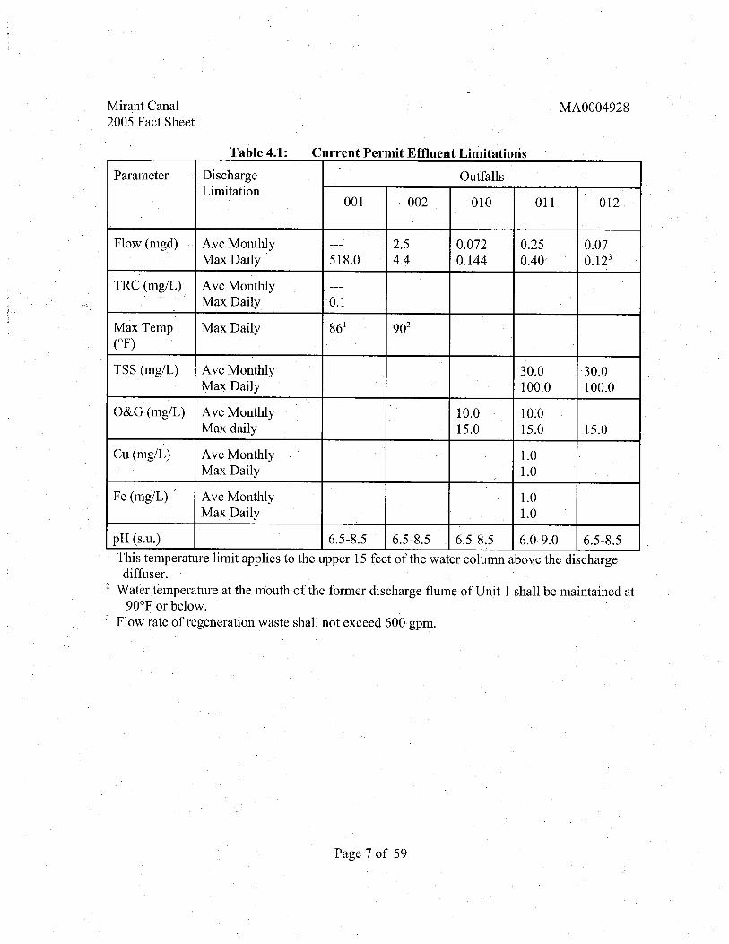
Table 4. Current Permit Effuent Limitations
MA0004928
Parameter Discharge OutfallsLimitation
002001 010 011 012
Flow (mgd) Ave Monthly 072Max Daily 518. 4.4 144 0.40
TRC (mg/L) Ave MonthlyMax Daily
Max Temp Max Daily
TSS (mg/L) Ave Monthly 30. 30.Max Daily 100. 100.
O&G(mg/L) Ave Monthly 10. 10.Max daily 15. 15. 15.
Cu (mg/L) Ave Monthly 1.0Max Daily 1.0
Fe (mg/L) . Ave Monthly 1.0Max Daily 1.0
pH (s.I This temperature limit applies to the upper 15 feet of the water column above the discharge
diffuser.2 Water temperature at the mouth of the forn1er discharge flume of Unit 1 shall be maintained at
F or below.3 Flow rate of regeneration waste shall not exceed 600 gpm.
Page 7 of 59

Mirant Canal2005 Fact Sheet
MA0004928
Table 4. Current Permit Monitorinl! Frequencies
Outfa,lls
Parameter Monitoring 001 002 010 011 012Requirements
Flow (mgd) Frequency: Continuous Estimate Continuous Continuous ContinuousSample Type: Daily Ave & Daily Daily Ave Daily Ave Daily Ave
Range & Range & Range & Range
TRC (mg/L) Frequency: lX/day except
weekendsSample Type: grab
Max Temp Frequency: Continuous Continuous
CF) Sample Type:I Instantaneous
Max,
TSS (mg/L) Frequency: Weekly XI 2 weeks
Sample Type: Grab 24hr. Comp
O&G (mg/L) Frequency: Weekly Weekly IX/2 weeksSample Type: Grab Grab Grab
Cu (mg/L) Frequency: WeeklySample Type: Grab
Fe (mg/L) Frequency: WeeklySample Type: Grab
pH (s, Frequency: Weekly XI 2 weeksSample Type: Grab grab
I The current permit requires that the temperature is "continuously recorded at the last accessiblepoint prior to discharge in the Cape Cod Canal."
2 The current permit indicates that pH "shall be monitored at a point prior to discharge into theCape Cod Canal."
Page 8 of 59
Mirant Canal2005 Fact Sheet
MA0004928
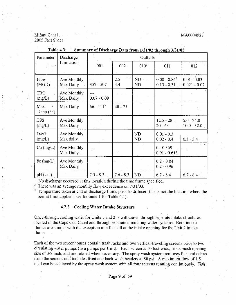
T bl 4 fD" h D t f 1/31/02 th h 3/31/05
. .
ummary 0 ISC ar2e a a rom rougJ
Parameter Discharge OutfallsLimitation
010001 002 011 012
Flow Ave Monthly 08 - 01 - 0.(MGD) Max Daily 357 - 507 4.4 13- 021 - 0.
TRC Ave Monthly(mg/L) Max Daily 07 - 0;
Max Max Daily 66 - 111 40 - 75Temp (O
TSS Ave Monthly 12. 5 - 28 0 - 24.(mg/L) Max Daily 20 - 63 10.0 - 32,
O&G Ave Monthly 01 - 0.(mg/L) Max daily 02 - 0.4 3 - 3.4
Cu (mg/L) Ave Monthly 0 - 0. 369Max Daily 01 - 0. 613
Fe (mg/L) Ave Monthly 0.2 - 0.Max Daily 2 - 0.
pH (s. 5 - 6 - 8. 7 - 8.4 7 - 8.4I No discharge occUlTed at this location during the time frame specified.2 There was an average monthly flow exceedence on 7/31/03.3 Temperature taken at end of discharge flume prior to diffuser (this is not the location where the
permit limit applies - see footnote 1 for Table 4. 1).
Cooling Water Intake Structure
Once- through cooling water for Units 1 and 2 is withdrawn through separate intake structureslocated in the Cape Cod Canal and through separate circulating water systems. Both intakeflumes are similar with the exception of a fish sil at the intake opening for the Unit 2 intakeflume.
Each of the two screenhouses contain trash racks and two vertical-traveling screens prior to twocirculating water pumps (two pumps per Unit). Each screen is 10 feet wide , has a mesh openingsize of 3/8 inch, and are rotated when necessary. The spray wash system removes fish and debrisfrom the screens and includes front and back wash headers at 80 psi. A maximum flow of 1.mgd can be achieved by the spray wash system with all four screens running continuously. Fish
Page 9 of 59

Mirant Canal2005 Fact Sheet
MA0004928
and debris from each intake structure are returned to the Canal via the old Unit 1 ' s dischargeflume located between the existing intakes , which is permitted discharge location Outfall 002.At low tide levels, the end of the fish return trough is suspended several feet over the surface ofthe water so that returned organisms vertically drop into the receiving water. Chlorinationinjection points are located in front of the intake screens. The Unit 1 condenser pumps are ratedat 85 000 gpm each and Unit 2' s pumps are rated at 95 500 gpm each (all four pumps combinedtotal 361 000 gpm).
At full flow , the approach velocities at the entrance to the intake structures are 1.2 feet/secondfor Unit 1 , and 1.1 feet/second for Unit 2. Each intake structure is approximately 135 feetlong;the distance from the entrance at the Cape Cod Canal to the screens/pump wells. The approachvelocities at the intake screens are 0.7 feet/second for Unit 1 and 0.8 feet/second for Unit 2.(Through screen velocities were not provided by the Facility).
Part A.1.g. of the Station s current permit indicates that the existing circulating water intakestructure is considered Best Technology Available (BT A) for minimizing adverse environmentalimpact in conformance with Section 3l6(b) of the CW A. For each permit reissuance , CW A 9
316(b) determinations must be revisited. The Draft Permit' s 9 3l6(b) determination is based onnew biological information and the assessment of existing technologies available that minimizeenvironmental impacts from the impingement and entrainment of organisms on intake screens.A complete discussion of this determination is found in Section 5.2.4 of this Fact Sheet. Themost recent impingement (1999-2000) and entrainment (1999-2002) studies performed by MRIare discussed in Mirant' s October 29 , 2003 , submittal and Section 5.2.2 of this Fact Sheet.
Permitted Outfalls
Outfall 001
Condenser cooling water, internal process wastewater and storm water discharge to a 25- footwide, 750-foot long open discharge flume (Outfall 001), and then through a buried conduitleading to a submerged slot diffuser located approximately 100 feet offshore and approximately925 feet from the intake structures. Internal process wastewater includes waste from outfalls 010(during emergencies), 011 , and 012. (See descriptions below.
Currently, samples for pH and chlorine are taken from a foot bridge located approximately halfway down the discharge flume. Temperature is continuously monitored at the end of the flumeprior to the diffuser.
The Station s circulating water system provides once-through cooling water to the condensersand uses approximately 518 mgd of water fromthe Cape Cod Canal. Flow is estimated frompump capacity curves and operational hours of the four constant velocity speed pumps. Theapproximate number of service hours per year for Unit 1 is 7 000 ( 65% capacity factor) and for
Page 10 of 59

Mirant Canal
2005 Fact SheetMA0004928
Unitl - 6 200 hours (40-45% capacity factor). The current discharge velocity from the diffuseris 3. 8 feet/second with a transit time of5.5 minutes from the condensers to the diffuser.
Three percent sodium hypochlorite injections (toprevent biofouling) begin on a daily basis whenwater temperature approaches and remains above approximately 50 F (i. , primarily duringsummer months). The sodium hypochlorite injection system is located prior to the trash racks , in
. front of the intake pump bays. The chlorine operation consists of continuous injection for onehour twice per day ('i hour each pump; 2 pumps/Unit). Maximum use equals 2 hours ofchlorination per Unit per day, equaling 4 hours/day total. The CUlTent permit includes a
maximum daily limit for Total Residual Chlorine (TRC) of 0. 1 mg/L but does not have anaverage monthly limit. Furthermore, the current permit only requires a grab sample to be takenonce per day (with no samples on weekends). See Section 4.4. 1 of the Fact Sheet for chlorinemonitoring requirements for location 001 of the Draft Permit.
The temperature of cooling water passing through the condensers is increased by a maximum ofabout 35 F above ambient. The current permit states that the temperature limit for Outfall 001 is
F for the upper 15 feet of the water column above the discharge diffuser (the portion of thewater colunm from the surface to a depth of 15'). However, temperature is being measured at theend of the discharge flume and not in the Canal above the diffuser. The 1976 report "CirculatingWater Discharge Temperature Survey" by NEGEA Service Corporation shows the con"elationbetween the discharge flume temperature and the temperature in the upper 15 feet of the watercolumn above the diffuser. The report provides calculations indicating that a temperature of
F in the upper 15 feet of the water column above the diffuser corresponds to a temperature ofl07 F in the discharge flume. The Draft Permit monitoring requirements wil serve to verity thereport' s calculations. Temperature limits for both locations are included in the Draft Permit.
Thermal discharges by the Station to the Canal at the temperatures authorized by the DraftPermit would exceed the numeric temperature criteria applicable to SB waters, as specified inthe Massachusetts Water Quality Standards. As a result, a variance from State Water QualityStandards under CW A 9 3l6( a) wil be needed to authorize this thermal discharge. This isdiscussed in more detail in Section 5.1 of this Fact Sheet.
There is no temperature differential (Ll T) limit in the current permit. Temperature differential(LlT) in this context refers to the difference in temperature of the water between the intake andthe discharge. This measurement is a reflection of the degree to which the Station s coolingsystem is heating up the water it withdraws from, uses , and then discharges back to , the Canal.Based on intake and discharge temperature data provided by the permittee, a temperaturedifferential (Ll T) limit of 33 OF has been established for the Draft Permit. This limiUs based on avariance under CW A 9 3l6(a). (See Section 5. 1 Thermal Discharge Effuent Limits of this Fact.
. Sheet.)
The Station perfonns a heated backwash treatment for removing debris from the condenser
Page 11 of 59

Mirant Canal2005 Fact Sheet
MA0004928
tubes. This may occur once per week for each Unit. The process takes approximately one hour(30 minutes for each side of the condenser) per Unit. There is no mention of this in the currentpermit. Station representatives explained that there is no discharge to the Cape Cod Canalduring this process because the reverse flow is pulled into the adjacent well and intake ratherthan to the Canal. According to the permittee , the process is not for the control ofbiofouling; itis solely to remove debris from the condenser tubes. The Draft Permit specifies that no discharge shall occur from this process operation.
Internal outfall locations 010 , 011 , and 012 also discharge to the main discharge flume (Outfall001). Therefore, along with chlorine and heat, the following pollutants may potentially be foundin the wastewater at this location: oil and grease (O&G), copper, iron, and TSS. These materialshowever, are regulated/permitted at the upstream internal outfall locations as described below.
Outfall 002
Outfall 002 is located between the Unit rand 2 intake strctures. The former condenserdischarge flume for Unit 1 is now used to discharge the intake screen wash water (includingimpinged fish) for both Units 1 and 2 , along with approximately J mgd of condenser water fromthe main discharge flume which is used to flush debris from the flume. Heatedcondensercooling water flows from the 001 flume through two pipes in the back wall of the 002 flume.
The current permit limits flow at this site to 2.5 mgd (ave. monthly) and 4.4 mgd (max. daily),and limits pH to between 6.5 and 8. 5 standard units (s. ). In addition, the current permitrequires that the temperature "at the mouth of the former discharge flume of Unit No. 1 shall
maintained at 90 F orbeIow." This temperature limit, which exceeds the maximum temperaturecriterion for SB waters under the State Water Quality Standards is retained in the Draft Permitand is based on a variance under CWA 9 316(a). Section 5.1 (Thermal Discharge EffuentLimits) ofthi Fact Sheet includes a discussion of the variance determination. A temperaturedifferential limit of33 F was also added to the Draft Permit for the discharge from Outfall 002and is also a variance-based limit. The s reen washing operation is intermittent. The condenser cooling water dischargescontinuously at this location through two 10" pipes located at the back of the flume, at a rate ofapproximately 1000 gpm per pipe (3 mgd - total). The cooling water is heated, periodicallychlorinated and at times contains internal waste streams, TRC monitoring at Outfall 002 is notrequired by the Station s current permit and temperature monitoring is conducted at the mouth the flume.
As previously mentioned, the chlorine injection system is located prior to the trash racks, in frontof the intake pump bays. For the protection of impinged organisms, the Draft Permit requiresthat the injection points be moved. In addition, the discharge of heated and chlorinatedcondenser water into the 002 flume is prohibited during times when the screen wash is in
Page 12 of 59

Mirant Canal2005 Fact Sheet
MA0004928
operation until upgrades can be made to the fish return system. The required upgrades to theintake structure fish return systems are discussed in Section5.2.4 of this Fact Sheet.Furthermore , the Draft Permit requires that there shall be no condenser water discharge at thislocation during the chlorination of any Unit condensers , thereby obviating the need for TRCmonitoring.
Outfall 010
Outfall 010 is used for the discharge of wastewater from Unit 1 floor drains after it has passedthrough an oil/water separator. Sources of wastewater includ vacuum and pump seal water, fuelheater room discharges , and boiler leaks. The company wants this location to remain on theirpermit although they currently divert this wastewater to the Unit 1 precipitator pump house forreuse in the precipitator ash sluice system. Station representatives indicate that this dischargewould only occur if there were an emergency situation, such as a massive boiler leak. This lastoccurred in 1994 and samples were collected. These waste sources are considered low volumewaste according to 40 C. R. 423 and TSS and Oil and Grease are required sampling parameters.Sampling frequency during any periods of discharge has been changed to daily in the DraftPermit to reflect the need for increased sampling during emergencies.
Outfalls 011 and 012
Under the current permit, low volume waste, metal cleaning waste and ash sluicing waste areallowed to be combined (in settling ponds) and discharged either through one of two treatment(neutralization) tanks or directly from the ponds. Low volume wastes consist of wastes fromfloor drains , water treatment (demineralizer and condensate polisher), boiler blowdownlaboratory wastewater, and boiler seal water. Metal cleaning wastes consist of wastes from airpreheater wash, boiler fireside wash, precipitator wash, boiler chemical cleaning, stack andbreach wash, equipment cleaning and feedwater heater chemical cleaning.
National Effuent Limitation Guidelines (technology-based)for the "Steam Electric PowerGenerating Point Source Categoty" are found at 40 C.F.R. Part 423. Effuent limitations are thesame for low volume wastes and fly ash wastes, although they are independently named wastestreams. Therefore , these wastes can be combined prior to sampling. However, the metalcleaning category includes different limits (i. , copper and iron). Therefore, the metal cleaningwaste sources are being separated from the low volume and fly ash waste in the Draft Permit. other words , 40 C.F.R. Part 423 requires that the technology,based limitations of these two wastestreams (combined low volume/fy ash and metal cleaning) be achieved independently. Underthe current permit the pennittee is allowed to dilute the metal cleaning wastes with the lowvolume/fy ash waste sources in the settling ponds such that metals could be discharged in excessof the discharge limitations at 40 C. R. Pmi 423. Dilution is not an acceptable means ofachieving technology-based limitations. In addition, if the metal cleaning wastes are greatlydiluted, removal of the pollutant metals in the metal cleaning wastes becomes more difficult andless efficient because of the dilution. The effuent guidelines at 40C. R. Part 423 were
Page 13 of 59

Mirant Canal2005 Fact Sheet
MA0004928
developed to take advantage of the higher removal efficiencies achievable by treating aconcentrated waste stream such as metal cleaning wastes. In order to fully assure complianceseparation of the two waste streams as named in the effuent guidelines at 40 C.F.R. 9423.12 isnecessary. The Draft Permit achieves this by imposing separate limits at a separate compliancepoint, and by requiring separate monitoring for the metal cleaning wastes.
With the separate monitoring and compliance of these two waste streams, the effuent limitationsapplied in the Draft Permit are technology-based requirements found at 40 C. R. Part 423. Formetal cleaning wastes (Outfall 011), the parameters limited inthe Draft Permit are as follows:total suspended solids , oil and grease , copper and iron. For low volume/fy ash waste (Outfall012), the parameters limited in the Draft Permit are: total suspended solids and oil and grease.
For this Draft Permit, Outfall 011 is the spigot on the discharge line of either ofthe twoneutralization tanks prior to discharging into the final effuent flume and refers to metal cleaningwaste streams only . As previously mentioned, metal cleaning wastes consist of wastes from airpreheater wash, boiler fireside wash, precipitator wash, boiler chemical cleaning, stack andbreach wash, equipment cleaning and feedwater heater chemical cleaning. Generally, mostmetal cleaning operations take place during Station outages. The Draft Permit prohibits thepermittee from combining any low volume or fly ash wastewater with metal cleanin,g
wastewater, including sludge dewatering filtrate , to insure that representative samples arecollected for compliance with the permit limits.
Testing of boiler chemical cleaning wastewater in June , 2005 showed low levels of mercury (0.4part per bilion (ppb) and 0.2 ppb in approximately 250 000 gallons). Further investigationfound that the concentration of mercury in the caustic that was used during the cleaning was 3ppb. At these concentrations , there is no reasonable potential to exceed the national waterquality criteria limit for mercury. This a toxic pollutant, however, that is known tobioaccumulate in the food chain and due to the ready availability of mercury-free caustic , it isnot necessary to discharge it to the receiving water. Therefore, as a best-management-practicethe Draft Permit requires that the permittee shall certity that all caustic used for metal cleaninghas no detectable levels of mercury. Furthermore, as was the case with mercury, there is apotential for other unexpected pollutants to be present in the boiler chemical cleaning effuent.Therefore , the Draft Permit requires that the composite sample of each boiler chemical cleaningevent is analyzed for petroleum hydrocarbons and priority pollutant metals - as well for allpollutants addressed by specific limits in the permit - to verify that mercury and other pollutantsare not present in the effuent.
The Station s existing permit specifies that Outfall 012 is for sampling only the blowdown fromthe Facility' s demineralizers and condensate polishers (water treatment wastes). As previouslymentioned, water treatment waste is considered one of several sources of low volume waste.Outfall 012 in the Draft Pennit includes all low volume and ash sluice waste sources combined.Low volume waste streams include water treatment wastes (demineralizer and condensatepolisher blowdown) as well as floor drain wastewater, boiler blowdown, laboratory wastewater
Page 14 of 59

Mirant Canal2005 Fact Sheet
MA0004928
and boiler seal water. Low volume waste is either mixed with fly ash waste or routed directly toone of the two neutralization tanks prior to discharge into the final effuent flume.
Fly ash waste in this context consists of wastewater from the ash sluice system and is alsodischarged through Outfall 012. The ash sluice system collects ash from the electrostaticprecipitators for Units 1 and 2 and pumps it to the ash thickener. Prior to thickening, caustic andpolymer are added to the sluice water to enhance overall settling characteristics and control thepH. Effuent from the thickener is then directed to one of three settling ponds (A , B , or C). Theponds are cement with an epoxy lining. Following settling, the ash sluice water is typicallyreturned to the clean water sump for recirculation to the ash precipitators. Periodic blowdownfor the system is required to prevent the buildup of dissolved solids and to manage treatmentpond levels. Blowdown and sludge dewatering filtrate is diverted to either waste pond D ordirectly to the neutralization tanks.
Waste pond D effuent is typically directed to neutralization tanks , although it can be dischargeddirectly to the main discharge flume, Outfall 012 wastewater is either sampled from one of thetwo treatment tanks or directly from one of the waste ponds.
4.4 Derivation of Effuent Limits for Pollutants Other Than Heat
This section discusses the basis for effuent discharge limits for pollutants other than heat.Limits forheat, as well as cooling water intake requirements , are discussed further below.Effuent limits for pollutants other than heat are based on whichever is more stringent betweenthe applicable technology standards and Water Quality Standards. National Effluent LimitationGuidelines for the "Steam Electric Power Generating Point Source Category" are found at 40C.F.R. Part 423. The Massachusetts State Water Quality Standards are found at 314 C.
00.
4.4. Chlorine
Acute Water-Ouality Based Limit (Maximum Daily), Outfall 001
The existing permit limits the Total Residual Chlorine (TRC) concentration to 0. 1 mg/l (dailymaximum) at Outfall 001. This limit was "established on the basis ofbioassays on Menhadenand State Certification requirements. This limit is more stringent than the 0.2 mg/l technologybased standard for Steam Electric Power Generating Point Sources (40 C. R. 9423. 13). EPAbelieves that the 0. 1 mg/llimit is also more stringent than any limit that would be derived basedon the State of Massachusetts ' acute water-quality standard for chlorine in marine water and thedilution provided by the receiving water.
Thermal Pollution Control in Massachusetts Coastal Waters" by John R. ElwoodWater Resources Commission Division of Water Pollution Control, January 1973 , p. 12.
Page 15 of 59

Mirant Canal2005 Fact Sheet
MA0004928
The Massachusetts Acute Chlorine Standard is 0.013 mg/l. To determine the dilution factorneeded for the permit limit of 0. 1 mg/l , the following formula is used:
Permit Limit = Standard x Dilution1 mg/l = (0.013 mg/l) x
In this case
, "
X" equals 7.7 which is the dilution factor which would be required to yield the 0.mg/l permit limit. Any greater dilution provided by the receiving water would allow for a higherpermit limit and any less dilution would require a more stringent limit.
It has been determined that the currents flowing in the westward direction (ebb tide) produce anaverage flow of 90 000 cubic feet per second (cfs) and currents flowing in the eastward direction(flood tide) produce an average flow of 74 000 cfs. In addition, the effuent is dischargedthrough a diffuserthat is 200 feet in length and contains 28 slots along the crown of thedistribution pipes. Each slot is 1.5 feet wide and approximately5 feet long. The slots direct thedischarge vertically upward into the Canal, providing rapid initial dilution and mixing withCanal water. In order for the effuent to be diluted by a factor of 7. , 6191 cfs of dilution water is needed(6191cfs/804cfs == 7. , where 804 cfs is the maximum permitted Station flow). This dilution willassure that the Water Quality Standard of 0.013 mg/l is met while allowing a permit limit of 0.mg/l, as explained above.
Considering the high current flows through the Cape Cod Canal; EP A believes there is alwaysmore than 6191 cfs of flow to dilute the effuent. Therefore, EP A is imposing a daily maximumlimit of 0. 1 mg/l for the Draft Pern1it. However, because the intake water contains bromides(i. , saline water), the sampling parameter has been changed from total residual chlorine to totalresidual oxidants (TRO) in accordance with the Steam Electric Power Generating Point SourceCategory effuent guidelines (see 40 C.F .R. 9 423. 11).
The effuent guidelines allow, at the permitting authority' s discretion, TRC/TRO limits tobeexpressed as either mass (pounds) or concentration (mg/l). The Draft Pennit includes aconcentration based TRO limit for Outfall 001.
Chronic Water Ouality Based Limit (Average Monthly). Outfall 001
The current permit has no average monthly limit for chlorine. Massachusetts regulations containa marine chronic criteria of 0.0075 mg/l for chlorine EP A believes a chronic limit
unnecessary because the permit limits chlorine use to twol1ours per day per unit. This restricted
Alden Research Laboratory, Inc. , Evaluation ofFish Protection Alternatives for theCanal Generating Station, October2003.
Page 16 of 59

Mirant Canal2005 Fact Sheet
MA0004928
use of chlorine wil not result in chronic exposure to aquatic life.
Effuent Guideline Limit (Instantaneous Maximum) Outfall 001
In the effuent guidelines for the "Steam Electric Power Generating Point Source CategoryEP A has established a technology-based maximum discharge concentration of 0.2 mg/l for totalresidual oxidants ("instantaneQus maximum ), based on the best available technologyeconomically achievable (BAT). The 0.2 mg/L "maximum concentration" limit is aninstantaneous maximum limit, meaning that it is the value that shall not be exceeded, at any
time , as clarified in EP A' s July 27 , 1992 , Memorandum from Cynthia Doughert, Director of thePermits Division, to the Regional Water Management Division Directors. This technology-based effuent limit applies to plants with a total generating capacity of more than 25 megawattsand once through cooling water systems. Each individual generating unit is prohibited fromdischarging chlorine for more than two hours per day, unless the discharger demonstrates to thepermitting authority that a longer duration is necessary in order to control macro-invertebrate.growth. In addition, simultaneous multi-unit chlorination is permitted according to the effuentguidelines.
Currently, Canal Station is cooled via an open cycle system (Once-Through Cooling Water).Biofouling ofthe Units 1 and 2 condenser tubing is controlled by the addition of chlorine, assodium hypochlorite (NaOCl), to the cooling water. During the summer months , the NaOClpumps for each Unit activate for one hour two times per day. Thus , each Unit receives a total of2 hours of chlorinationper day.
The above derived, technology-based TRO limit shall be measured at Outfall 001 , prior todischarge into the Cape Cod Canal. . As noted above , the effuent guidelines specity that permitlimits for TRO shall be set as an "instantaneous maximum." EP A is not aware of continuouschlorine monitoring equipment for use in salt or brackish water that currently satisfies theanalytical requirements of 40C.F. Part 136, Table lB. Therefore , in order to more accuratelydetermine that the concentration is below the limit for the duration of the chlorination eventEP A requires that at least one sample is collected and analyzed every half hour duringchlorination.
Subject to the restrictions discussed above, the Draft Permit authorizes the use of chlorine as thebiocide for the Unit 1 and 2 condensers. Except for chlorine, no other biocide shall be usedwithout prior written approval from the EPA and MA DEP.
4.4.2 .
The pH range for Class SB waters is from 6, 5 to 8.5 standard units (s. ) and not more than 0.2units outside of the normally occurring range as defined in the Massachusetts Surface WaterQuality Standards , found at 314 C. R. 4.00. Unless otherwise specified, pH shall be measuredat Outfalls 001 and 002. Monitoring for pH at the internal outfalls 010, 011 , and 012 is not
Page 17 of 59

Mirant Canal2005 Fact Sheet
MA0004928
necessary as explained in EP A" s March 21 , 1986 , Memorandum from Charles Kaplan , EP A'
National Steam Electric/Water Expert, to Regional Permit Branch Chiefs and State Directors.Using dilution to accomplish the neutralization of pH is preferable to adding chemicals.
4.4. Polychlorinated Biphenyl Compounds
Pursuant to 40 C.F.R. Part 423 , discharge ofpolychlo'rinated biphenyl compounds (PCBs) isprohibited and any PCB' s at the facility must be disposed of in accordance with 40 C.F .R. Part
761.
4.4.4 TSS
The quantity of Total Suspended Solids (TSS) that can be discharged from low volume wastestreams , fly ash transport water and metal cleaning wastes is limited under 40 C.F.R. 9423.12by multiplying the flow of low volume waste sources times the concentration listed in the
following table " which is 100 mg/l daily maximum and 30 mg/l monthly average. The DraftPermit contains TSS limits based on these requirements. In addition, 40 C. R. 9423. 12(b)(1l)states that the permitting authority has the discretion to express the limits as concentration basedas opposed to mass-based. The Draft Permit includes concentration-based TSS limits for Outfalllocations 010 , 011, and 012. .
4.4. Oil and Grease
The current permit' s maximum daily limit for Oil and Grease for Outfall locations 010, 011 and012 is 15 mg/l. Although 40 C. R. 9423.12 sets a maximum daily limit for Oil and Grease of
, 20 mg/l, the current permit limits wil be maintained in the Draft Permit in accordance withanti-backsliding" provisions. Similarly, the average monthly limit is 10 mg/L in the current
permit for Outfall1ocations 010 and 011, which wil be maintained in the Draft Permit. There isno average monthly limit for O&G in the Station s cl,rrent permit for Outfall 012. Therefore, in 'accordance with 40 C.F.R. 9423. , the a:verage monthly limit in the Draft Permit for location012 is 15 mg/L.
4.4. Copper
The applicable technology-based national effuent limitation guideline for copper specified in 40C.F.R. Part 423 is based on the concentration of copper in the metal cleaning waste flow. Themetal cleaning waste stream is routed to one of two waste treatment tanks (Outfall 011) prior todischarge into the discharge canal. The effuent limitation guidelines set a maximum daily limitof 1.0 mg/l and a 30-day average value of 1.0 mg/l. These limits are included in the DraftPermit.
Iron
Page l80f 59

Mirant Canal2005 Fact Sheet
MA0004928
As inthe case of copper, the effuent limitation guidelines at 40 C. R. Part 423 set a maximum. daily limit for iron of 1.0 mg/l and a 30-day average value of 1.0mg/l for the metal cleaningwaste stream(Outfall 011).
Whole Effuent Toxicity
EPA' s March 1991
, "
Technical Support Document for Water Quality-Based Toxics Control"(EPA/505/2-90-00l), recommends using an "integrated strategy" containing both pollutantspecific (chemical) approaches and whole effuent (biological) toxicity approaches to betterdetect toxics in effuent discharges, Such infonnation may then be used to control the entranceof those toxic pollutants into the nation s waterways. Pollutant-specific approaches, such asthose in the Gold Book and State regulations, address individual chemicals, whereas wholeeffuent toxicity approaches can evaluate the effects of possible interactions between pollutants
, the "Additive
, "
Antagonistic " and/or " Synergistic" effects of pollutants. In addition, the. presence of an unkown toxic pollutant can potentially be discovered and addressed through thisprocess.
Section 1 01(a)(3) of the CW A specifically makes it national policy to prohibit the discharge oftoxic pollutants in toxic amounts , and such discharges are also prohibited by the Massachusetts
. Water Quality Standards which state , in part that
, "
all surface waters shall be free from pollutantsin concentrations or combinations that are toxic to humans, aquatic life or wildlife." TheNPDES regulations under 40 CFR 9122.44(d)(1)(v) require whole effuent toxicity (WET) limitsin a permit when a discharge has a "reasonable potential" to cause or contribute to an excursionabove the State s narrative criterion for toxicity.
Region I adopted this "integrated strategy" on July 1 , 1991 , for use in permit development andissuance. EPA Region I modified this strategy to protect aquatic life and human health in amanner that is both cost effective as well as environmentally protective.
Mirant Canal discharges wastewater which has an unown potential for causing toxicity toorganisms. Presently, there is inadequate infonnation for EPA to base a "reasonable potential"determination concerning this discharge s potential to cause or contribute to an excursion of theState s narrative water quality criterion for toxicity. Thus, an inclusion of a WET testingmonitoring requirement in the draft permit is necessary, reasonable and appropriate to gather thisinformation in order to make a technically-based "reasonable potential" determination regardingwhether or not this discharger is unkowingly contributing toxics to the receiving water. Thisapproach is consistent with that recommended in March 1991
, "
Technical Support Document forWater Quality-based Toxics Control" (EPA/505/2-90-001 , page 60).
This WET testis a proactive method of protecting the environment so as to properly carr outEPA' s Congressional mandate to prevent the discharge oftoxic substances into the Nationwaterway. EPA cannot make a "reasonable potential" determination on an individual dischargewithout first evaluating WET test results obtained from a given facility' s discharge,
Page 19 of 59

Mirant Canal2005 Fact Sheet
MA0004928
Therefore , the Draft Permit is requires the permittee to reportthe results of chronic (andmodified acute) WET tests using Inland Silverside (Menidia beryllna) and chronic Sea UrchinArbacia punctulata) WET tests on a quarterly basis. If after eight consecutive sampling periods
(two years), no toxicity is found, the permittee may request a reduction in toxicity testing.
Cooling Water-Related Limits Under Section 316 of the Clean Water Act
With any National Pollutant Discharge Elimination System (NPDES) permit issuance orreissuance, EPA is required to evaluate compliance with applicable standards. For some permitsthis includes the application of the standards stated in CW A 9 3l6( a) regarding thermaldischarges and CW A 9 3l6(b) regarding cooling water intake structures. CW A 9 3l6( a) appliesif the permit applicant seeks a variance from technology-based and/or water quality-based
effuent limits for the discharge of heat. To obtain the variance; the applicant must demonstrateto the satisfaction of the EP A (or, if appropriate, the State) that the alternative effuentlimitations proposed wil assure the protection aI)d propagation of a balanced, indigenouspopulation of shellfish, fish , and wildlife in and on the receiving water body. 33 U.S. c. 91326(a); 40 C. R. 9 125.70. CWA 93l6(b) applies if the discharger seeks to withdraw coolingwater from a water of the United States. To satisfy 9 3l6(b), the permit applicant mustdemonstrate to the satisfaction of the EP A (or, if appropriate , the State) that the location, design
construction, and capacity of the facility s cooling water intake structue(s) (CWIS5 reflect theBest Technology Available (BT A) for minimizing adverse environmental impacts. 33 U.S.c. 9
l326(b); 40 C.F.R. 99401.14 and 1 22.44(b)(3); 40 C.F.R. Part 125; Subpart I and 1.
Both CWA 99 3l6(a) and 3l6(b) apply to this permit; 9 3l6(a) due to the proposed thennaldischarge in excess of that allowed by State Water Quality Standards and the Permittee s requestfor a 9 3l6( a) variance , and 9 3l6(b) due to the presence and operation of cooling water intakestructures at Canal Station. '
Thermal Discharge Limits
In developing a permit' s effuent limits , EPA compares technology-based and water quality-based requirements , and whichever is more stringent governs the permit requirements. Forthermal discharges , however, EPA may also consider granting a variance under CWA 9 3l6(a)from the technology-based and/or water quality-based limits if less stringent variance-basedlimits will nevertheless be sufficient to "assure the protection and propagation of a balancedindigenous population of shellfish , fish, and wildlife" (BIP) in and on the water body receivingthe discharge. As a practical matter, EP A has with some permits proceeded directly todeveloping permit limitations under a Section 3l6( a) variance if a set of limitations weredetermined to be sufficient to assure protection and propagation of the BIP. In such casesdetermining the technology-based and water quality-based limitations would serve no practicalpurpose.
Mirant Canal Station discharges heated effuent via a discharge canal and a submerged slot
. Page 20 of 59

Mirant Canal2005 Fact Sheet
MA0004928
diffuser. In addition, the old discharge canal for Unit 1 also contains some heated waterdischarged from the main discharge canal via two ten-inch pipes. A detailed description of thisfacility, its discharge canals and submerged slot diffuser may be found in Sections 1. , 4.2 and
3 of this Fact Sheet.
In 1999 , Canal Station conducted a detailed thermal monitoring study to measure the extent of itsthermal plume. This study consisted of two separate parts: 1. a two month survey using anumber of fixed thermistors; and 2. an intense one day survey using measurements from fixedthermistors and multiple observations from a boat. In addition, Canal Station has generated ahydrodynamic model to predict temperature contours within the canal. This model has beencalibrated using the field results from the 1999 survey.
The work described above shows that the thennal plume from Canal Station is predominantly asurface feature with limited penetration into the water column. Surface temperatues during themonitoring in July of 1999 peaked at 24 , while bottom water temperatures peaked atapproximately 19- C. The thermal plume is quickly dissipated by the strong currents thatwash through the Canal. There is a very limited area on the surface near the point of dischargethat exhibits an increase of? 4 C over ambient temperatures. A thermal plume with a "delta-of 2 C can be seen over an area that does span across the canal to the opposite bank. . Howevereven this plume, is in a fairly small geographic area (see Figure 5.1 as anexample).
The state classification for the receiving waters (namely, the Cape Cod Canal) of the Mirantfacility s discharge is Class SB. Thus , the Water Quality Standards require that the in-streamwater temperature shall exceed neither 85 F (29.4 C) nor a maximum daily mean of80(26. C), and the rise in temperature due to a discharge shall exceed neither 1.5 F (0. C) duringthe summer months (July through Septemher) nor 4 F (2.2 C) during the winter months(October through June). Furthermore, any mixing zone applied to this discharge to achieveWater Quality Standards , must conform to the mixing zone requirements for the Water QualityStandards,
3 Mirant Canal NPDES Permit Application No. MA0004928 , October 30 , 2003Attachment B, p. 22.
Page 21 of 59

Mirant Canal2005 Fact Sheet
Figure 5.1: Thermal Plume from Mirant Canal Station
Figure 3. Contours Of suriace temperatures between 09:18- 10: 11 on 27 July 1999,
Figure 3, Contours of surface temperalures between 1 0:24 11: 11 on 27 July 1999.
Page 22 of 59
MA0004928
Temp F
C 76
, ,
: 74
- :
t ::
Acc

Mirant Canal
2005 Fact Sheet
ording to CWA 9 316(a), and EPA regulations promulgated thereunder at 40 C.F.R. Part 125subpart thern1al discharge effuent limits in permits may be less stringent than those requiredby otherwise applicable standards if the discharger demonstrates that such limits are morestringent than necessary to assure the protection and propagation of the BIP. This demonstrationmust show that the alternative thermal discharge limits desired by the discharger, considering thecumulative impact of its thermal discharge together with aU other significant impacts on thespecies effected see 40 C.F.R. 9 l25.73(a), wil assure the protection and propagation of the BIPin and on the body of water into which the discharge is made. The thermal discharge limits inMirant Canal' s existing permit were based on a 9 316( a) variance, and Mirant Canal hasrequested the continuation this variance based on its demonstration made in the October 302003 , supplement to its NPDES Permit Application, Section B. .
MA0004928
EP A has reviewed the 1999 Thermal Monitoring Program and Hydrodynamic Modeling Studyof the Cape Cod Canal at Canal Station (Mirant Canal, 2003). While EPA d es not necessarilyagree with all of the species-specific thermal tolerance summaries presented in. this documentEPA has assessed the document's thermal plume information. Based on EPA' sreviewofthethermal monitoring results and the hydrodynamic modeling, EPA agrees with Canal Stationconclusions that the thermal plume is primarily a surface phenomenon. It appears that theabsolute temperature values in the State Water Quality Standards would be met very close to thepoint of discharge. However, the change in temperature would exceed the state Delta, Tstandard. The projected exceedence would be small and again primarily limited to the surface.Based on our knowledge of the thermal plume and the thermal tolerances of aquatic speciesknown to be present in the Cape Cod Canal (see Section 6. , Table 6.2 of this Fact Sheet), EP does not believe that the continued discharge from Canal Station wil result in appreciable harmto the BIP. Furthermore , EPA is not aware of any biological evidence of past appreciable harmto the BIP from the Station s existing thermal discharge, As a result, EP A approves the 9 3l6( a)variance proposed by the permittee with no increase in thermal discharge from previous permitconditions.
The Draft Permit grants a 9 3l6( a) variance to allow the discharge of heat to the Cape Cod Canalin excess of the numeric. criteria for temperature in the Massachusetts Water Quality Standards.A' 9 3l6( a) variance is issued for Outfall 001, that allows a maximum instantaneous temperatureof 1 F. As mentioned in Section 4.3 - Outfall 001 , water discharged at this temperatue ispredicted to result in a maximum temperature of 86 F (29. C) in the upper 15 feet of the watercolumn above the discharge diffuser, which is lOF above the numeric water quality criterion of
This is evidence of the dissipation of the heat in the thermal discharge once it is mixed withCanal water via the diffuser. The Draft Permit (Part LA.2. ) includes a requirement to measurethe temperature at this location (i, , in the Canal , above the diffuser) in order to verity the 86limit is not exceeded. In addition, based on intake and discharge temperature data provided bythe permittee, a temperature differential (i1 T) variance limit of 33 OF has been granted for theDraft Permit at this location. It is EP A' s judgement tbat this i1T , in conjunction with the
Page 23 of 59

Mirant Canal2005 Fact Sheet
MA0004928
maximum temperature limit, is protective of the BIP.
EP A is also granting a 9 3l6( a) variance to allow the discharge of heat at Outfall 002 in excessof the numeric criterion for temperature in the Water Quality Standards. The Draft Permitretains the previous maximum limit of 90 F at the end of the fish/debris return discharge flume.In addition, a temperature differential (LlT) variance limit of33 F has been granted for the DraftPermit at this location. Compared to the maximum flow for Outfall 001 , which is 518 miliongallons per day (mgd), the maximum flow limit at Outfall 002 is significantly smaller at 4.4 mgd.It stands to reason that if modeling showed a high heat dispersion at Outfall 001 , then the
relatively small discharge at Outfall 002 would have a much smaller thermal impact.Furthermore , the Draft Permit offers additional protection for impinged organisms by requiringthat heated and chlorinated condenser water shall not be discharged into this flume during theoperation of the current fish return system. It is EP A' s judgement that this Ll T at Outfall 002 , inconjunction with the maximum temperature limit, is also protective of the BIP.
EPA assumes that these variance-based effuent limits are less stringent than either waterquality-based or technology-based limits would require without conducting a comprehensivederivation of such water quality-based or technology-based limits. There is no reason to engagein such a comprehensive derivation, however, given EPA' s conclusion that the r-equestedvariance-based limits wil assure the protection and propagation of the BIP in compliance withCWA 9 3l6(a).
Cooling Water Intake Structure Requirements under CWA 316(b)
Discussion of I"egal Requirements
This section presents EPA' s determination with respect to the application ofCW A 9 316(b), 339 1326(b), to the Draft NPDESpern1it for Mirant Canal. CW A 9 3l6(b) governs
requirements related to cooling water intake structures (CWISs) and requires "that the locationdesign, construction, and capacity of cooling water intake structures reflect the best technologyavailable for minimizing adverse environmental impact." The operation of CWISs can cause orcontribute to a variety of adverse environmental effects, such as killng or injuring fish larvaeand eggs by entraining them in the water withdrawn from a water body and sent through thefacility s cooling system, or by killng or injuring fish and other organisms by impinging themagainst the intake structure s screens.
Permit Based on Best Professional Judgement
In the absence of detailed regulations , EPA has for many years made CW A 9 3l6(b)determinations on a case-by-case, best professional judgement (BPJ) basis , for both new andexisting facilities with regulated CWISs. In December, 2001 , EP A promulgated new, final 93l6(b) regulations providing sp cific technology standard requirements for new power plantsand other typesofnew facilities with CWISs. 66 Fed. Reg. 65255 (Dec. 18 2001) (effective
Page 24 of 59

Mirant Canal2005 Fact Sheet
MA0004928
date of the regulations is January 17 2002). These regulations do not, however, apply to existingfacilities such as Mirant Canal.
EP A also has developed regulations applying CW A 9 3l6(b) to large, existing power plants.The new CW A 9 3l6(b) regulations addressing large existing power plants are referred to as thePhase II Regulations" and were published in the Federal Register on July 9 , 2004. 65 Fed. Reg.
41576 (July 9 , 2004) (Final Rule). The Phase II Regulations became effective on September 72004, and are promulgated at 40 C. R. Part 125 , SubpartJ. Mirant Canal is subject to the PhaseII Regulations based 011 the applicability provisions of 40 C. R. 9 125.91. Although it shouldbe noted that various industry groups , environmental groups , and several states have fiedcurrently pending litigation challenging the legality of the Phase II Regulations, the regulationscunently remain in effect.
In making determinations under the CW A 9 3l6(b) new Phase II regulation, EP A must considerenvironmental/ecological issues , engineering issues , economic issues related to the cost ofimplem nting CWIS technology options , legal issues , and, ultimately, policy issues regardingthe final choice of appropriate steps to minimize adverse environmental effects. These issues , aswell as the permit conditions arising from EP A' s CW A 9 3l6(b) determinations for the DraftPelmit for Canal Station, are addressed below.
The Phase II Regulations identify five different options from which a Phase II existing facilitymay choose an approach for achieving compliance with the regulations. Permit applicationrequirements vary based on the compliance alternative(s) selected and, for some facilitiesinclude development of a Comprehensive Demonstration Study. See 40 C.F.R. 9 125.95. The
Phase II Regulations establish performance standards for the reduction of impingement mortalityand , under certain circumstances , for the reduction of entrainment (e. , reduce itppingementmortality by 80 to 95 percent, and reduce entrainment by 60 to 90 percent). The applicability the performance standards is determined by several factors , including the type of water body onwhich the facility is located, the facility' s capacity utilization rate , and the proportion of thevolume of the source waterbodythat is withdrawn by the facility. Under the Phase IIRegulations , the applicable performance standards can be met by design and constructiontechnologies, operational measures , restoration measures , or some combination thereof. See 40
R. 9 125.94 (discussion of compliance alternatives).
The Phase II Regulations prescribe a number of interrelated decisions to be made by EP A andthe permittee during a multi-step process of infornmtion collection, submission and reviewleading up to permit issuance. For example , the rule requires EP A to evaluate , using informationsubmitted in the permittee s application and bi-annual status reports , and any other availableinformation, the performance of any technologies , operational measures , and/or restorationmeasures the permittee may have implemented in previous permit terms. As another example, ifa permittee chooses to propose restoration measures as part of its approach to satistying theapplicable performance standards under the rule, EP A would need to evaluate the proposal anddetermine its acceptability under the rule , as well as how it would be monitored if approved.
Page 25 of 59

Mirant Canal2005 Fact Sheet
MA0004928
Clearly, working through all the potential issues could be a difficult, time-consuming process.(See 69 Fed. Reg. 415 , 41631 - 41633 (July 9 , 2004) (discussion of time needed for
. application process under Phase II Regulations).
Understandably, given the timing of this Draft Permit and the relatively recent publication of thenew Phase II Regulations , the permittee has not yet submitted a complete informationsubmission addressing all of the new requirements under the Phase II Regulations. The Phase IIRegulations directly address this type of problem ina manner designed to allow ongoingpermitting to continue without undue delay because of the new regulations. The Phase IIRegulations proyide a reasonable approach during the transition from BPJ-based permitting topermitting with limits based on the application of the new requirements in the Phase IIRegulations using the information required to be submitted under 40 C. 9 125.95. This
approach is to allow the permitting authority to continue issuing new permits with 9 3l6(b)limits based on BPJ under certain circumstances. These circumstances apply in the case of theCanal Station permit. Therefore, EP A is setting CW A9 3l6(b) permit limits based on BP Jbecause doing so is consistent with the new Phase II R gulations.
Specifically, 40 C.F.R. 99 125.95(a)(2)(i) and (ii) of the Phase II Regulations state the following(emphasis added):
(i) You must submit your NPDES permit application inaccordance with the time frames specified in 40 C.F.l22.2l(d)(2); (ii) If your existing permit expires before July 9, 2008 , you mayrequest that the Director establish a schedule for you to submit theinformation required by this section as expeditiously as practicable, but not later than January 7 , 2008. Between the timeyour existing permit expires and the time an NPDES permitcontaining requirements consistent with this subpart is issued toyour facilty, the best technology available to minimize adverseenvironmental impact wil continue to be determined based on theDirector s best professionaljudgment.
Applying this regulation to this case, one sees that the existing permit for Canal Station expiredseveral years ago (in 1994) and that the permittee also fied its permit application several yearsago. In addition, the permittee has not submitted all of the information required by the Phase IIRegulations. Therefore , EP A could not presently develop a permit "containing requirementsconsistent with this subpart" and is , instead, currently issuing the permit to the Station with 9316(b) limits that "continue to be detennined based on the Director s (i. , permittingauthority' s) best professional judgment."This approach to permitting during the period of transition from continued use of the BPJapproach to developing CW A 9 3l6(b) permit limits using the information required in 40
R.9 125.95 is a reasonable and appropriate scheme which seeks to prevent undue delay to
Page 26 of 59

Mirant Canal2005 Fact Sheet
MA0004928
ongoing permitting as a result of the new regulations. This approach is consistent with theCW A' s goal of continued progress toward achieving the restoration and maintenance of thechemical, physical and biological integrity of the Nation s water bodies. See 33 U.S.c. 9
l251(a)(1). Moreover, if it later turns out that for some reason the Phase II Regulations are notin effect at the time this Final Permit becomes effective (e. , they have been stayed or remanded
as a result of the litigation that has been filed regarding the new regulations), then the FinalPermit would still have a proper BPJ-based foundation for its 9 316(b) requirements.
The above explanation of how to properly develop limits under CWA 9 3l6(b) for the StationFinal Permifin light of the new Phase II Regulations is confirmed by the discussion provided inthe August 19 , 2004 , set of "Questions and Answers" posted' on EP A' s website
www,epa, gov/waterscience/316b) . In Section 2 of that document, Question & Answer No.explains how to address permitting circumstances such as those of Canal Station:
Q3: The Draft Permit is proposed after the 3l6(b) Phase II rule takes effect. Atthe time of permit issuance , the facility has not submitted the comprehensivedemonstration study and other information needed to determine limitations underthe 316(b) Phase II rule. What is the basis for the 3l6(b) limitations in the permit?
A3: The 3l6(b) limitations in the proposed and Pinal Permit would be based onBPl under authority of 40 C.F.R. 9 l25.95(a)(2)(ii). The permit would also needto include a schedule requiring the facility to submit the comprehensivedemonstration study and other infonnation required by 40 C.F.R. 9 125.95 as
expeditiously as practicable but not later than January 7 , 2008,
In this case , Canal Station s permit expired June 23 , 1994 , and the permittee has not to date
submitted all of the information required by the Phase II Regulations. Therefore, EP A may issue
a Final Permit to the Station with 9 3l6(b) limits that "continue to be determined based on the
Director s best professional judgment." As a result, EP A has , in fact, determined BT A for this
Draft Permit based on BPl. The guidance further indicates that under these circumstances
, "
the
permit would also need to include a schedule requiring the facility to submit the comprehensivedemonstration study and other information required by 40 C.F.R. 9 125.95 as expeditiously as
practicable , but no later than January 7 , 2008." Such a schedule is included in the Draft Permit
in Part LA.8. This schedule also is consistent with the schedule contained in EPA' s letter of
December 30 , 2004 , to the permittee requesting submission of the necessary information under40 C.P.R. 9 125. , with a Proposal for Information Collection due byOctober 7 2006. It is
likely that information collected under the proposed requirements of the Draft Permit would be
able to be used in fulfillng the permit application requirements of 40 C.F.R. 9125.95 of the
3l6(b) Phase II Regulation.
State Water Qualiy Standards
Page 27 of 59

Mirant Canal2005 Fact Sheet
MA0004928
State legal requirements , including state Water Quality Standards , also may apply to thedevelopment of permit conditions for cooling water intakestructures. In tbis caseMassachusetts Water Quality Standards apply and the Commonwealth has in the past confirmedthat its Water Quality Standards , as well as other state law requirements , do , in fact, apply to
regulating the adverse environmental effects of cooling water intake structures. Thus , the DraftPennit' s limits under CW A 9 3l6(b) must also be sufficiently stringent not to cause or contributeto a violation of Massachusetts Water Quality Standards , including designated uses and narrativecriteria.
State Water Quality Standards set designated uses for water bodies within the state and specifynarrative and numeric criteria that the water bodies must satisfy. Pern1it conditions must be
designed to satisfy applicable criteria and protect designated uses , including those for fishhabitat. CW A 99 301(b)(1)(C) and 402(a) require that permits include "any more stringentlimitation, including those necessary to meet Water Quality Standards , treatment standards , or
schedules of compliance, established pursuant to any state law or regulations (under authority ofsection 1370 of this title ((i. , CW A 951 Om . . . , or required to implement any applicable Water
QualityStandard established pursuant to this chapter." 33 U. C. 9 131 1 (b)(1)(C). Section301(b)(I)(C)'s mandate applies regardless of whether EPA or a state is the permit issuingauthority and, for an EPA-issued permit, applies regardless of whether the state expresslydemands that such conditions be placed in the permit. In addition, CWA 9 510 clearlyauthorizes states to impose more stringent water pollution control standards than dictated by thefederal statute, at least where the statute does not expressly forbid such tougher state standards.In the regulations governing the development of-Water Quality Standards, 40 C. R. 9 13 L4(a)
states that
, "
(aJs recognized by section 510 of the Clean Water Act, states may develop Water
Quality Standards more stringent than required by this regulation." The Supreme Court in PUD
No. 511 U.S. at 705 , citedto this regulation in support of the view that states could adoptwater quality requirements more stringent than federal requirements. See also 40 C.F.R. 99
125.90(d) and 125.94(e).
In the context of the state certification process under CW A 9 401 , the Supreme Court has alsoheld that once the state certification process has been triggered by the existence of a dischargethen the state s certification may impose conditions and limitations on the activity as a wholenot merely on the discharge , to the extent needed to ensure compliance with state Water QualityStandards or other applicable requirements of state law. Thus , the Court stated:
The text (of CW A 9 401 d) J refers to the compliance of the applicant, not thedischarge. Section 401 (d) thus allows the State to impose "other limitations" onthe project in general to assure compliance with various provisions of the CleanWater Act and with "any other appropriate requirement of State law.
" . ..
SeCtion
401 (a) (1 ) identifies the category of activities subject to certification - namely,those with discharges. And 9 40 I( d) is most reasonably read as authorizingadditional conditions and limitations on the activity as a whole once the threshold
Page 28 of 59
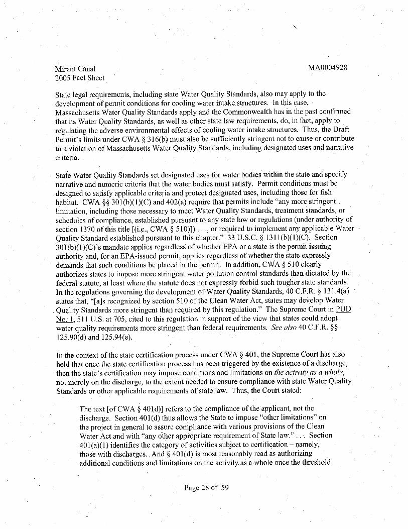
Mirant Canal2005 Fact Sheet
MA0004928
State legal requirements , including state Water Quality Standards , also may apply to thedevelopment of permit conditions for cooling water intake structures. In tbis caseMassachusetts Water Quality Standards apply and the Commonwealth has in the past confirmedthat its Water Quality Standards , as well as other state law requirements , do , in fact, apply to
regulating the adverse environmental effects of cooling water intake structures. Thus, the DraftPennit' s limits under CW A 9 3l6(b) must also be sufficiently stringent not to cause or contributeto a violation of Massachusetts Water Quality Standards, including designated uses and narrativecriteria.
State Water Quality Standards set designated uses for water bodies within the state and specifynarrative and numeric criteria that the water bodies must satisfy. Permit conditions must bedesigned to satisty applicable criteria and protect designated uses, including those for fishhabitat. cWA 99 30 1 (b)(1)(C) and 402(a) require that permits include "any more stringentlimitation, including those necessary to meet Water Quality Standards , treatment standards , or
schedules of compliance, established pursuant to any state law or regulations (under authority ofsection 1370 of this title ((i. , CWA 9 5l0)J) . . . , or required to implement any applicable Water
Quality Standard established pursuant to this chapter." 33 U.S. C. 9 131 1 (b)(I)(c). Section301(b)(1)(C)' s mandate applies regardless of whether EPA or a state is the permit i suingauthority and, for an EPA-issued permit, applies regardless of whether the state expresslydemands that such conditions be placed in the permit. In addition, CWA 9 510 clearlyauthorizes states to impose more stringent water pollution control standards than dictated by thefederal statute, at least where the statute does not expressly forbid such tougher state standards.In the regulations governing the development of-Water Quality Standards, 40 C. R. 9 l3L4(a)statesthat (aJs recognized by section 510 of the Clean Water Act, states may develop Water
Quality Standards more stringent than required by this regulation." The Supreme Court in PUD
No. 511 U.S. at 705 , cited to this regulation in support of the view that states could adoptwater quality requirements more stringent than federal requirements. See also 40 C.F.R. 99
125.90(d) and l25.94(e).
In the context of the state certification process under CW A 9 401, the Supreme Court has alsoheld that once the state certification process has been triggered by the existence of a dischargethen the state s certification may impose conditions and limitations on the activity as a wholenot merely on the discharge , to the extent needed to ensure compliance with state Water QualityStandards or other applicable requirements of state law. Thus , the Court stated:
The text (of CW A 9 401 d) J refers to the compliance of the applicant, not thedischarge. Section 401 (d) thus allows the State to impose "other limitations" onthe project in general to assure compliance with various provisions of the CleanWater Act and with "any other appropriate requirement of State law.
" . ..
SeCtion
401 (a)(1) identifies the category of activities subject to certification - namely,those with discharges. And 9 401(d) is most reasonably read as authorizingadditional conditions and limitations on the activity as a whole once the threshold
Page 28 of 59

Mirant Canal2005 Fact Sheet
MA0004928
condition, the existence of a discharge, is satisfied. PUD No. , 511 U. S. at 711-12.
Thus , for example , a state could impose certification conditions related to cooling water intakestructures on a permit for a facility with a discharge , if those conditions were necessary to assurecompliance with a requirement of state law, such as to protect a designated use under StateWater Quality Standards. See Id. at 713. This also confirms that in setting discharge conditionsto achieve W ter QmilityStandards , a state can and should take account of the effects of otheraspects ottheactivity, such as cooling water withdrawals , that may affect the dischargeconditions that will be needed to attain Water Quality Standards.
In sum, the limits in EP A-issued NPDES permits that address cooling water intake structuresmust satisty both CW A 9 3l6(b) and any applicable state requirements , such as Water QualityStandards. As indicated above, Canal Station withdraws water for its cooling system from theCape Cod Canal. These waters have been classified as "SB" by the state and, as such , the
designated uses for these waters include providing good quality habitat for fish and other aquaticlife as well as a resource for primary and secondary contact recreation (which includes fishing).Thus , the permit's limits under CW A 9 3l6(b) should ensure that cooling water intakeoperations do not cause or ,contribute to a failure to attain these designated uses. TheMassachusetts Department of Environmental Protection (MA DEP) has primary responsibilityfor determining what permit limits are necessary to achieve compliance with state lawrequirements, (EPA' s independent responsibilities under CW A 30 1 (b)(1)(C) are discussedabove.) Since the NPDES permit that EPA expects to issue to Canal Station wil be subject state certification under CW A 9 401 , the permit wil also need to satisty any conditions of such acertification. EP Aanticipates that the MA DEP wil address its certification after issuance ofthis Draft Permit but before issuance of the Final Permit.
Biological Impacts
Section 3l6(b) of the Clean Water Act addresses the adverse environmental impact of coolingwater intake structures at facilities requiring NPDES pern1its. Adverse environmental impact bycooling water intake structures results from the. entrainment of fish eggs and larvae and othersmall forms of aquatic life through the plant's cooling system and from the impingement of fishand other larger forms of aquatic life on the intake screens. This entrainment and impingementcan contribute to reductions of local species of commercial and/or recreational importancelocally important forage species , and local threatened or endangered species. Any ofthese losses
See also 40 C. R. 99 125.90(d) and l25. 94(e) (provisions in Phase II regulationsmandating that cooling water intake structure requirements in permit also must satisty.any morestringent state requirements); and 40 C.F.R. 99 l25.80(d) and l25. 84(e) (parallel provisions inthe Phase 1 regulations).
Page 29 of 59

Mirant Canal2005 Fact Sheet
MA0004928
could contribute to a decrease in the diversity of the ecosystem.
In developing this permit, EP A analyzed impingement and entrainment data collected by thepermittee in order to assess the adverse environmental impact on all life stages of local species offish and invertebrates. As may be expected in this type of biological sampling data, there is
considerable temporal variation in impingement and entrainment sampling results from 1999 to2001 , between particular calendar months from 1999 to 20Q 1 , and within each year.
The permittee developed a list of species considered to be a priority based upon their presence inthe Cape Cod Canal in significant numbers for significant periods of time and their importanceunder the Essential Fish Habitat (EFH) program. This list, developed in coordination with theMassachusetts Division of Marine Fisheries and the National Marine Fisheries Service , provideda focus for the permittee to assess impingement and entrainment effects to species in the localecosystem. The pern1itteefurther analyzed this list of species and assigned these species toseveral categories including Priority Species , Critical Aquatic Organisms , and RepresentativeImportant Species based upon level of impingement and ent ainment, ecological and commercialimportance, and availability of required life history data.
EP A acknowledges the usefulness of these specific categories for the discussion of adverseenvironmental impacts. However, in assessing the adverse effects of the cooling water intakestructures , EP A considered not only entrainment and impingement of fish in these categories , butalso all other relevant available information from Canal Station, including information aboutthose local species listed under the EFH program, as well as the previously mentioned biologicalstudies to determine adverse environmental impact to the local ecosystem.
Entrainment
Entrainment of organisms occurs when water is withdrawn by a facility into the cooling waterintake structure from an adjacent water body. Eggs and larvae are typically small enough to passthrough the mesh of the intake screens and become entrained within the facility. As a result, the
eggs and larvae are exposed to shear forces from mechanical pumps, physical stress or injury,elevated temperatures from waste heat removal , and, in some cases , high concentrations ofchlorine or other biocides. These organisms can be kiled or otherwise harmed as a result ofentrainment. The extent of entrainment of fish and invertebrates in cooling water intakestructures is determined by several factors , including the nature of the water body in which thecooling water intake structure is located, the particular location in the water body in which theintake structure is placed, the biological community present in the water body, the volume andvelocity of the intake flow, the nature of any intake screening system or other entrainment
5 "Final Regulations To Establish Requirements for Cooling Water Intake Structures atPhase II Existing Facilities; Final Rule " Federal Register, Vol. 69 , No. 131 , Friday, July, 92004, p. 41586.
Page 30 of 59

Mirant Canal2005 Fact Sheet
MA0004928
reduction equipment used by the facility, and season. The number of organisms that becomeentrained is dependent upon the flow of cooling water through the plant and the concentration oforganisms in the source water body that are small enough to passthrough the screens of theplant's intake structure(s). Given the nature of the entrainment process and the vulnerabilities ofthe organisms being entrained, EP A assumes 100% mortality of entrained organisms in order todetermine adverse environmental impacts to local fish and invertebrate populations , unless apermittee provides a site-specific study justitying use of a lower mortality rate.
The type of water body, such as a river, ocean or estuary, on which the cooling water intakestructure is located plays a role in the entrainment of organisms. Cooling water intake structureslocated on bodies of water with large concentrations of entrainable organisms are more likely toentrain organisms. , In this type of habitat, the variety and number of species entrained in theintake structures is higher than in other ecosystems. For example , estuaries provide keyspawning and nursery habitat for many species of fish and, as a result, they often containrelatively high concentrations of fish eggs and larvae and juvenile fish.
The location of the cooling water intake structure within a water body also can playa role in re-entrainment of organisms if the discharge is located close to intake structures. Particularly in ahigh-velocity environment, tidal flows can direct organisms back toward the intake structures.
The presence and density of vulnerable life stages , such as eggs and larvae, are affected byseasonality and, thus , seasonality also is a, factor in entrainment. Additionally, the size of theseeggs and larvae relative to the mesh size of any intake baniers wil also playa role inentrainment because an intake banier with very small mesh might be able to block some largertypes of eggs and larvae from being entrained, whereas other eggs and larvae may be so smallthat no currently available barrier system technology would be capable of blocking them frombeing entrained. Depending upon season, different species are affected more or less than othersand may peak in entrainment samples when the concentration of eggs is at a maximum. Theresult could be a substantial loss to a population of a particular year class. Losses due toentrainment at peak spawning times could not only affect current and future populations andtheir reproductive capacity, but also could affect the food source for other species.
The Cape Cod Canal supports a diverse assemblage of organisms , including a number of speci. that are commercially and/or recreationally important. A number of fish species, such as winter
flounder, have regionally been in declilie. Fishery managers have been implementingincreasingly restrictive fishing limitations on a variety of stocks in hopes of stimulating arecovery. There is no evidence to suggest that stocks in the Cape Cod Canal are in worsecondition than the regional stocks. However, it is important to reduce the cumulative mortalityexperienced by fish stocks to help stimulate recovery.
6 "Final Regulations To Establish Requirements for Cooling Water Intake Structures atPhase II Existing Facilities; Final Rule " 69 Fed. Reg. 41620 (July, 9 , 2004).
Page 31 of 59

Mirant Canal2005 Fact Sheet
MA0004928
The permittee conducted entrainment sampling from February 1999 through February 2002.
From March through August of each year, weekly samples were collected. From Septemberthrough February, samples were collected twice per month. During each sampling week, three
samples were collected, each on different days. The permittee used a 0.333-mm mesh , 60-cm
diameter plankton net placed in the discharge canal approximately 20 meters downstream fromthe head wall for sampling. Each sample fitration volume was approximately 100 m3 and was
measured using a digital flow meter mounted in the mouth of the net. After each sampleinterval , the sample was transferred to ajar containing sufficient formalin to produce 5% to 10%
solution. The ichthyoplankton samples collected through June 15 2001 , were analyzed in thelaboratory, and the remaining samples were archived. According to the permittee, all fish eggsand larvae were identified to the lowest distinguishable taxonomic category and counted.Certain eggs , particularly the early stages of development, could not be identified to the specieslevel. In such cases , species were grouped. These groupings are described in detail in thepermittee s NPDES application. The methodology used by Mirant Canal , LLC to collectentrainment data is described in more detail in Appendix i , Section C. l of the Mirant CanalNPDES Permit Application No. MA0004928.
The complete results of this sampling conducted by the permittee are presented in the NPDESapplication for Mirant Canal Station. Based on this sampling, the permittee estimated that 2.6 to
6 billion eggs and 187-318 milion larvae per year were entrained by the power plant. Datasummarizing the loss of organisms by entrainment in the Mirant Canal Station cooling waterintake structures is presented in Table 5. 1. The pemiittee calculated annual entrainmentestimates , shown in Table 5. , for eighteen species representing sensitive species commonlyfound in entrainment samples from Mirant Canal Station in 1999-2000 and 2000-2001. The eggsand larvae of several Essential Fish Habitat species (e. , hake , flounder and Atlantic mackerel)were found in significant numbers in entrainment samples. Seasonal differences in the speciesdominating in entrainment samples were observed, with Atlantic herring, sand lancesculpins/grubby and Atlantic cod particularly abundant in the winter and early spring. Cunnertautog, winter flounder, hake, menhaden and Atlantic mackerel were more often abundant duringearly summer. 8 Additionally, several speeies found in entrainment samples at Canal Station areforage species , those that provide an important food source for other species. Losses in foragespecies could have both immediate and long-term effects that could threaten the developmentand growth of species dependent upon these forage species as a food source.
Table 5.1: Annual Estimates of Finfish and Invertebrates Entrained at Canal Station
7 Mirant Canal NPDES Permit Application No. MA0004928 , October 2003 , Attachment, pp. Al-3 through Al-
Ibid.
Page 32 of 59

Mirant Canal2005 Fact Sheet
MA0004928
The permittee conducted entrainment sampling from February 1999 through February 2002.
From March through August of each year, weekly samples were collected. From Septemberthrough February, samples were. collected twice per month. During each sampling week, three
samples were collected, each on different days. The permittee used a 0.333-mm mesh, 60-cm
diameter plankton net placed in the discharge canal approximately 20 meters downstream fromthe head wall for sampling. Each sample filtration volume was approximately 100 m and was
measured using a digital flow meter mounted in the mouth of the net. After each sample
interval, the sample was transferred to ajar containing sufficient formalin to produce 5% to 10%
solution. The ichthyoplankton samples collected through June 15 , 200l were analyzed in thelaboratory, and the remaining samples were archived. According to the permittee, all fish eggsand larvae were identified to the lowest distinguishable taxonomic category and counted.Certain eggs , particularly the early stages of development, could not be identified to the specieslevel. In such cases , species were grouped. These groupings are described in detail in thepermittee s NPDES application. The methodology used by Mirant Canal, LLC to collectentrainment data is described in more detail in Appendix i , Section C. l of the Mirant CanalNPDES Permit Application No. MA0004928.
The complete results of this sampling conducted by the permittee are presentedjn tl)e NPDESapplication for Mirant Canal Station. Based on this sampling, the permittee estimated that 2.6 to
6 bilion eggs and 187-318 millon larvae peryear were entrained by the power plant. Datasummarizing the loss of organisms by entrainment in the Mirant Canal Station cooling waterintake structures is presented in Table 5. 1. The permittee calculated annual entrainmentestimates , shown in Table 5. , for eighteen species representing sensitive species commonlyfound in entrainment samples from Mirant Canal Station in 1999-2000 and 2000-2001. The eggsand larvae of several Essential Fish Habitat species (e. , hake, flounder and Atlantic mackerel)were found in significant numbers in entrainment samples. Seasonal differences in the speciesdominating in entrainment samples were observed, with Atlantic herring, sand lancesculpins/grubby and Atlantic cod particularly abundant in the winter and early spring. Cunnertautog, winter flounder, hake, menhaden and Atlantic mackerel were more often abundant duringearly summer. 8 Additionally, several speeies found in entrainment samples at Canal Station areforage species , those that provide an important food source for other species. Losses in forage
, species could have both immediate and long-term effects that could threaten the developmentand growth of species dependent upon these forage species as a food source.
Table 5.1: Annual Estimates of Finfish and Invertebrates Entrained at Canal Station
7 Mirant Canal NPDES Permit Application No. MA0004928 , October 2003 , Attachment, pp. Al-3 through Al-
Ibid.
Page 32 of 59

Mirant Canal2005 Fact Sheet
MA0004928
CommonName Eggs Eggs Larvae Larvae
(1999-2000) (2000-2001) (1999- (2000-2001)2000)
River Herring - Alewife 000 22,000 102 000
(Alosa pseudoharengus)
Atlantic Menhaden 997 000 220 000 907,000 359 000
(Brevoortia tyrannus)
Atlantic Herring250 000 925 000
(Clupea harengus)
Atlantic Cod 908 000 131,000 587,000 286 000
(Gadus morhua)
Pollock(Pollachius virens)
Hake - 108 000 069 000 830 000 294 000
Red (Urophycis chuss)Spotted (Urophycisregia)White (Urophycis tenuis)
Silversides232,000 404 000
(Menidia menidia)
Sculpins473 000 639,000
Grubby (Myoxocephalusaenaeus))
Striped Bass(Morone saxatils)
Scup 759 000 000 662 000 506 000
(Stenotomus chrysops)
Cunner 227 814 000 883 771 000 33, 116 000 865 000
(Tautogolabrusadspersus)
Tautog 119, 109 000 154 118 000 974 000 136 000
(Tautoga onits)
Sand Lance 128 000 505 000 871 000
(Ammodytes americanus)
Page 33 of 59

MirantCanal2005 Fact Sheet
MA0004928
Atlantic Mackerel 208 344 000' 269 581 000 892 000 017 000(Scomber scombrus)
Windowpane Flounder 691 000 806 000 735 000 385 000(Scophthalamusaquosus)
Winter Flounder 082 000 927 000 888 000 068 000(Pleuronectesamericanus)
Y ellowtail Flounder 419 000 730 000 702 000 054 000(Pleuronectesferruginea)
American Lobster 883 000 000(Homarus americanus)
Additionally, the permittee also calculated estimates of entrainment losses using all equivalentadult analysis. In general , this analysis assumes that only a certain percentage of eggs and larvaewould survive to adulthood. An adult equivalent analysis is one appropriate factor to consider inan overall assessment of the magnitude of the adverse impact of entrainment. It is not, howeverthe only factor to consider and such an analysis has certain limitations. For example, it does notconsider or evaluate whether cullng a large number of eggs and larvae from an area maypotentially harm the area spopulation by weakening or destroying its compensatory reserve. Inaddition, this analysis does not factor in the resource value of eggs and larvae and individual lifestages. As mentioned above , eggs and larvae are a food source for many species and losseswithin these life stages represent losses to the area s overall energy budget and food web atmultiple trophic levels. Table 5.2 contains the number of equivalent adults lost due toentrainment as estimated by the permittee using egg and larval entrainment data from Table 5.
Table 5.2: Estimated Number of Equivalent Adult Species Entrained at Canal Station
Page 34 of 59
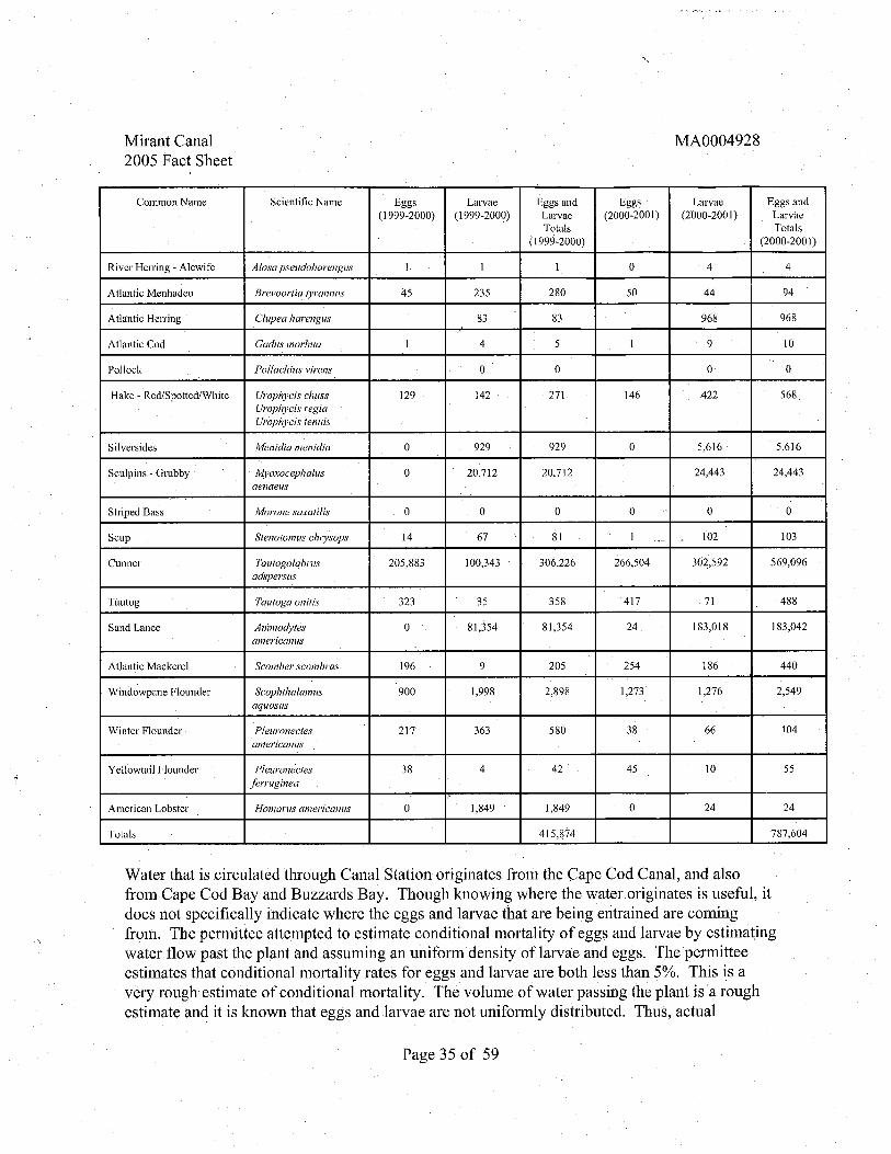
Mirant Canal2005 Fact Sheet
MA0004928
Common Name Scientific Name Eggs LaIvae Eggs and Egg Larvae Eggs and
(1999-2000) (1999-2000) Larvae (2000-2001) (2000-2001) LarvaeTotals Totals
(1999-2000) (2000-200 I)
River Herring - Alewife Alosa pseudoharengus
Atlantic Menhaden Brevoortia tyrannus 235 280
Atlantic HelTing Clupea harengus 968 968
At1antic Cod Gadus morhua
Po11ock Pol/achius v!l'ens
Hake- Red/Spotted/White Urophycis chuss 129 142 271 146 422 568Urophycis regiaUrophycis tenuis
Silversides !lienidia menidia 929 929 616 616
Sculpins - Grubby Myoxocephalus 712 712 443 443aenaeus
Striped Bass Morone saxatilis
Scup Stenotomus cll1YSOPS 67 102 103
Cunner Tautogolabrus 205 883 100 343 306 226 266 504 302 592 569 096adspersus
Tautog Tautoga onilis 323 358 417 488
Sand Lance Animodytes 354 354 183 018 183 042american us
Atlantic Mackerel Scomber scombrus. 196 205 254 186 440
Windowpane Flounder Scophthalamus 900 998 898 273 1,276 549aquosus
Winter Flounder Pleuronectes 217 363 580 104
americanus
Ye110wtail Flounder Pleuronectes
ferruginea
American Lobster Homarus americanus 849 849
Totals 415 874 787 604
Water that is circulated through Canal Station originates from the Cape Cod Canal, and alsofrom Cape Cod Bay and Buzzards Bay. Though knowing where the water originates is useful, itdoes not specifically indicate where the eggs and larvae that are being entrained are comingfrom. The pennittee attempted to estimate conditional mortality of eggs and larvae by estimatingwater flow past the plant and assuming an unifonn density of larvae and eggs. The pennitteeestimates that conditional mortality rates for eggs and larvae are both less than 5%. This is avery rough estimate of conditional mortality. The volume of water passing the plant is ' a roughestimate and it is known that eggs and larvae are not unifonnly distributed. Thus , actual
Page 35 of 59
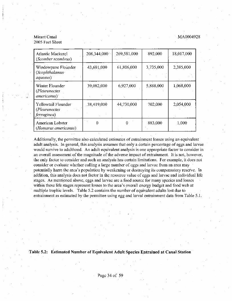
MirantCanal2005 Fact Sheet
MA0004928
Atlantic Mackerel 208 344 000' 269 581 000 892 000 Ol7 000(Scomber scombrus)
Windowpane Flounder 691 000 806 000 735 000 385 000, (Scophthalamusaquosus)
Winter Flounder 39,082 000 927 000 888 000 068 000(Pleuronectesamericanus)
Y ellowtail Flounder 4l9 000 730 000 702 000 054 000(Pleuronectes
jerruginea)
American Lobster 883 000 000(Homarus americanus)
Additionally, the pennittee also calculated estimates of entrainment losses using an equivalentadult analysis. In general , this analysis assumes that only a certain percentage of eggs and larvaewould survive to adulthood. An adult equivalent analysis is one appropriate factorto consider inan overall assessment of the magnitude of the adverse impact of entrainment. It is not, howeverthe only factorto consider and such an analysis has certain limitations. For example, it does notconsider or evaluate whether cullng a large number of eggs and larvae from an area maypotentially harm the area spopulation by weakening or destroying its compensatory reserve. Inaddition, this analysis does not factor in the resoUrce value of eggs and larvae and individual lifestages. As mentioned above , eggs and larvae are a food source for many species and losseswithin these life. stages represent losses to the area s overall energy budget and food web atmultiple trophic levels. Table 5.2 contains the number of equivalent adults lost due toentrainment as estimated by the pennittee using egg and larval entrainment data from Table 5.
Table 5.2: Estimated Number of Equivalent Adult Species Entrained at Canal Station
Page 34 of 59

Mirant Canal2005 Fact Sheet,
MA0004928
conditional mortality could be much higher.
Based on the overall numbers described above , EP A concludes that Canal entrainment is takinga substantial number of fish eggs and larvae and that under CW A g 316(b), the design, locationconstruction and capacity of Canal Station s cooling water intake structures must reflect the BestTechnology Available for minimizing these adverse impacts.
b Impingem.ent
Impingement of organisms occurs when water is drawn into a facility through its cooling waterintake structures and organisms too large to pass through the protective screens and unable toswim away become trapped against the screens and other parts of the intake structure. Thequantity of organisms impinged is a function of the intake structure s location, its depth , the
velocity of water at the entrance of the intake structure and through the screens ' the seasonalabundance of various species offish , and the size of various fish relative to the size of the meshin any intake barrier system (e. , screens). Intake strcture location is an important factor that may have an impact on the organisms thatbecome impinged. Generally, selecting locations to avoid important spawning areas, juvenilerearing areas , fish migration paths , shellfish beds or areas of particular importance for aquaticlife is one means of reducing impingement mortality.
Depth of the intake structure relative to the depth of the water body may also have an effect onthe type of organisms that become impinged. Benthic' organisms are more susceptible toimpingement than those that are pelagic or free-swimming, if the intake structure is situated onthe bottom of a waterbody. Pelagic fish tend to be stronger swimmers and have. some ability toavoid impingement, whereas benthic organisms such as lobsters and winter flounder, may evenenter an intake structure to seek refuge and become impinged.
The velocity of water entering the intake structure and moving through the intake screens areother important factors that contribute to the impingement of organisms. Some species of fishare attracted by the high veloyity water movement at the entrance to the intake structure and thiscan result in higher impingement rates. Approach velocity is generally lower than through-screen velocity, but may direct fish towards the CWIS. Through-screen velocity that is higherthan the approach velocity may prevent escape and result in fish being held against the screens ofthe CWIS , leading to injury or death.
Seasonal abundance and size of various species of fish also contribute to higher impingementrates. While adults are susceptible to impingement, juvenile fish are generally weaker swimmersand tend to become impinged more often and in greater numbers than adults. Injury to fishincluding de scaling, exhaustion, asphyxiation and starvation may occur due to impact against the
Page 36 of 59

Mirant Canal2005 Fact Sheet
MA0004928
traveling screens. Once injured, a fish that is released via the fish return system has thepotential to become progressively weakened and unable to survive due to the injury.Impingement of juvenile fish or other smaller organisms is likely to result in mortality due to theinability of the organisms to withstand the force of being trapped on the traveling screens.
MirantCanal Station uses separate cooling water intake structures for Unit 1 and Unit 2. Theintake structure for Unit 1 is situated on the bottom of the Canal at an elevation of -25.0 feet (ft),while the intake structure for Unit 2 , which was installed several years after Unit 1 , has a 9 footfish sill that elevates the entrance of the intake from -35.0 ft to -26.0 ft. This Unit 2 fish sill wasinstalled to reduce impingement losses of winter flounder by reducing the number of fishentering the intake structure. 1O As previously mentioned, the location of the intake structure hasan effect on the level of impingement. At Mirant Canal Station, the height of the Unit 2 intakestructure above the bottom may reduce the level of impingement of benthic organisms in Unit 2as compared to the level of impingement of benthic organisms in Unit l.
The original Unit 1 discharge canal located between the two intake structures now serves toreturn impinged fish and seaweed back to the Cape Cod Canal. Fish are returned via sluicewaysfrom both the Unit 1 and the Unit2 CWIS' s. The location of the original Unit 1 discharge canalbetween the two CWIS' s increases the potential for fish to become re-impinged because oncefish return to the high-velocity Cape Cod Canal , they may become re-impinged in either the Unit1 or the Unit 2 intake structure. Whether they are re- impinged on the Unit 1 or Unit 2 CWISdepends on the direction of tidal flow when the fish emerge from the discharge channel to theCape Cod Canal. . Other aspects of the fish return system that may contribute to impingementmortality are discussed in Sections 4. 2 and 4.3 (Outfall 002) of this Fact Sheet and include:location of the chlorination points lack offish buckets on the screens , use of high pressure spraywash, nOJ?-continuous rotation of screens , and the vertical drop of returned organisms to thewater during low tide levels.
The pern1ittee collected data on impingement rates and mortality from February 26 , 1999 untilMarch 31, 2000. Sampling occurred three times a week: once in the morning, once in theafternoon and once at night. Each Unit was sampled separately. Typically, both Units ' screenswere sampled simultaneously. Occasionally, if a pump was out of service, only one screen infront of the operating pump was sampled. Collections were made by placing a 3/8-inch (9.mm) stainless steel basket in the screenwash return sluiceway. Sampling was typically a
9 "Final Regulations To Establish Requirements for Cooling Water Intake Structures atPhase II Existing Facilities; Final Rule. Federal Register, Vol. 69, No. 13l , Friday July, 9 , 2004P 41586.
10 Ph.D. Thesis , Boston Univ. Marine Program, Boston, MA. Collings , W. , C.C.Sheenan et al. , 1981. The effects of power generation of some living resources of the Cape CodCanal and approaches. Massachusetts Dept. of Fisheries.
Page 37 of 59

Mirant Canal2005 Fact Sheet
MA0004928
minimum of two hours as recorded from the end of the previous wash to the end of the CUlTent
wash. Occasionally, such as during high fish impingement events or when seaweed wasabundant, screens were operated continuously. On these occasions a one-hour sample wascollected. Upon completion of each collection, the contents ofthe baskets were examined.Amounts of mixed wet algae were approximated in gallons. Fish retained by the basket werecollected, identified, and enumerated. All fish were measured to the nearest mm total length. Inlarge collections , 25 individuals per species were measured, the remainder counted. All fishwere immediately examined for initial condition (e.g. live, dead , injured). Any fish that wasalive or injured at the time of collection was placed in a 20-gallon holding tank supplied withcontinuously running ambient seawater. Latent survival was detennined after 48 hours. Themethodology used by Mirant Canal , LLC to collect impingement data is described in more detailin Appendix 1 , Section C.1 of the October 30 2003 , Mirant Canal NPDES Pennit ApplicationNo. MA0004928.
The complete results of this sampling conducted by the permittee are presented in the NPDESapplication for Mirant Canal Station. Data summarizing the loss of organisms by impingementmortality in MirantCanal Station is presented in Table 5. 3. The pennittee calculated ammalimpingement mortality from daily estimates. Most impingement events occulTed during
, November and December and were dominated by Atlantic menhaden, silverside al1d river
herring (alewife and blueback helTing). Alewife, Atlantic menhaden and silversides , allimportant forage species , were among those fish species most commonly identified inimpingement samples and the most vulnerable to impingement mortality at Mirant Canal Station.
Table 5. Annual Estimates of Impingement Mortality by Species of Finfishand Invertebrates at Canal Station
Common Name Scientific Name Annual Estimates of ImpingementMortality
(1999-2000)
River HelTing - Alewife Alosa pseudoharengus 779
Atlantic Menhaden Brevoortia t)'1"nnus 23,901
Atlantic HelTing Clupea harengus 230
Fourbeard Rockling Enchelyopus cimbrius
Atlantic Cod Gadus morhua 671
Po11ock Pol/achius v!l'ens 234
Hake - Red/Spotted/White Uroph)'cis chuss 131
Uroph)'cis I egiaUroph)'cis lenuis
Si I versides Menidia menidia 742
Searobin Prionotus
Sculpins - Grubby !l1)'oxocephalus' aenaeus 997
Page 38 of 59

Mirant Canal2005 FactSheet
MA0004928
Striped Bass Morone saxatilis
Scup Stenotomus ch1J'sops 374
Tautog Toutoga onitis 231
CUnner Tautogalabrus ad~persus 624
Sand Lance Ammod)'tes americanus
Atlantic Mackerel Scomber scombrus
Butterfish Peprilus triacanthus 505
Windowpane Flounder Scophlhalamus aquosus
Winter Flounder Pleuronecles american us 542
Ye110wtail Flounder Pleuronecles ferruginea
American Lobster H011al'lI Gl11eric017l1S 438
Total Loss Due to Impingement 623
The pennittee makes the assumption of complete mortality for all impinged organisms for theanalysis of impingement data presented in Table 5.3. The impingement data collected by thepennittee docUlhentsadverse impacts to large numbers offish and invertebrates from the CapeCod Canal due to Canal Station s two CWIS' s. This Draft Permit addresses the impacts due toimpingement with Best Technology Available (BTA) measures to minimize this adverseenvironmental impact as described in Section 5.2.4 of this Fact Sheet.
c Summary: Entrainment and Impingement Impacts
Mirant Canal Station withdraws approximately 518 milion gallons of water per day from theCape Cod Canal. Estimates of entrainment and impingement mortality calculated by thepennittee show that approximately 2. 6 to 3.6 bilion eggs and 187-318 milion larvae per yearare entrained, while over 71 000 individuals per year are impinged in Mirant Canal Station. Forthe two years of sampling perfonned, the permittee estimated that 415 874 and 787 604 annual
equivalent adults were lost due to entrainment. EP A considers these losses due to impingementand entrainment to be substantial. Reducing impingement mortality and entrainment from theexisting conditions wil reduce adverse impacts to organisms using the Cape Cod Canal nearMirant Canal Station.
Technological Options
This section discusses some of the potentially available , practicable technological alternativesfor ensuring that the design, construction, location and capacity of the CWISs at Mirant Canalreflect the BTA for minimizing adverse environmental impacts , as required by CWA g 316(b).This discussion considers engineering, environmental and , at a general level, economic issuesrelated to these alternatives and is based on EP A knowledge regarding CWIS technology and our
Page 39 of 59
Mirant Canal2005 Fact Sheet
MA0004928
review of the supplemental infonnation the permittee submitted to EPA on October 30 , 2003. Inaddition, this section explains why some alternatives were or were not considered components ofBT A in the Draft Permit.
Canal Station retained Alden Research Laboratory, Inc. (Alden), to help develop its response toEP A' s Request for Supplemental Infonnation, dated April 30 , 2003. As requested, Alden
evaluated the effectiveness of different fish protection technologies- for the cooling water intakestructures at Mirant Canal. Alden s report
, "
Evaluation of Fish Protection Alternatives for theCanal Generating Station (hereinafter refelTed to as "the Report"), summarizes the features andoperations of Canal' s CWIS' s , presents several technology and flow reduction alternatives , and
provides a detailed evaluation or'selected designs and the estimated costs for the alternativesselected.
The Report discusses numerous possible technologies for Canal , including those within thefollowing categories: physical balTiers , collection systems , diversion systems, and behavioraldeterrent technologies. From these bptions, the Report identifies six alternatives for furtherdetailed evaluation because they were considered commercially available practic,able from anengineering stand-point, and potentially effective forreducing impingement mortality andlorentrainment at Canal Station. These six alternatives were:
1- Expand Intake and Install Fine Mesh Ristroph Screens
2- Retrofit Intake with Submerged, Cylindrical Wedge Wire Screens
3- Retrofit Intake with BalTier Net
4- Install Coarse Mesh RistrophScreens. in Existing Intake
5- Modified Plant Operations (Flow Limitation)
6- Retrofit Plant with Closed-Cycle Cooling System
Each option was assessed for the following:
(1) technical considerations associated with design, installation, operatIon, and
maintenance;(2) estimated construction costs and operating and maintenance costs, including forreplacement power; and(3) estimated effcacy at reducing entrainment and impingement rates or impingementmortality .
The following discussion summarizes the Report's technological evaluations.
Page 40 of 59
Mirant Canal2005 Fact Sheet
MA0004928
Alternativel- Expand Intake and Install Fine Mesh Ristroph Screens
Alternative 1 involves expanding each intake structue by addition of another intake bay at eachCWIS. The existing traveling screens would be replaced with new flush-mounted , fine-meshRistroph screens. With these changes , the approach velocity would be reduced fromapproximately 0. 7 or 0.8 ftlsecond cUlTently, to approximately 0.5 ft/second(which isapproximately 1 foot/second through-screen velocity). New fish return and debris troughswould also be installed with the screens. The intakes would be equipped with a low pressurespray wash and fish return system and a separate high pressure spray wash and debris returnsystem. The new fish and debris return systems would discharge at either end of each Unit sothat during ebb tide, debrislfish trough flow for both Units would discharge west of the intakesand during flood tide debrislfish trough flow would discharge east of the intakes. The new fishreturn system would reduce both .impingement mortality and the probability of fish being re-impinged on the intake screens.
The constrction cost for this option is estimated at $10.41 milion. Also , it was determined thatthe operation and maintenance costs of the Ristroph screens and circulating water pumps wouldbe similar to that for the existing system. Although, continuous screen washing would occuronly during times of high debris loading or periods of high fish impingement/entrainment, theO&M costs were ' calculated based on twelve months of continuous operation. (See Alden, Table
5 Cost Comparison of Evaluated Alternatives , p; 5-
, The Report concludes that the fine mesh Ristroph screens would reduce to some extent theentrainment of eggs and larvae through the circulating water system: The diameters of eggs andhead capsule size of the species most commonly entrained at Canal were evaluated and it wasdetennined that "substantial retention would be expected for some of the species and life-stagescommonly entrained " but that the eggs of other species ' (such as tautog and cunner) would betoo small for entrainment prevention. 11 In the preamble to the Phase II Regulations , EPAindicates that in some cases
, " ...
fine mesh traveling screens with fish return systems have beenshown to achieve 80 to 90 percent or greater reduction in entrainment compared to conventionalonce-through systems. (See 69 Fed. Reg. 41599 (July 9 , 2004).) Alden s Report does nothowever, find that fine mesh Ristroph screens would achieve this level of perfonnanceat Canal.Instead, as stated above , the Report concludes that they would provide some level ofimprovement for some species. The Report also points out that to the extent that these screensprevent entrainment of some organisms , they wil necessarily impinge them and some of theseeggs and larvae wil not survive the effects of impingement. Such impingement mortality wouldoffset the benefits of entrainment reduction. EP A agrees with the appraisal of this technology:namely, that it would likely result in some level of improvement but that there are limits to whatit can achieve and additional study would be needed to characterize its overall effect. As a
11 Alden Research Laboratory, Inc.
, "
EvaluatIon ofFish Protection Alternatives for theCanalGenerating Station , October 2003 , p. 4-
Page 41 of 59
Mirant Canal2005 Fact Sheet
MA0004928
result, EP A does not at this time designate this option as BT A for Canal Station s NPDESPennit, though further, future analysis of this technology may be walTanted.
Alternative 2 - Retrofit Intake with Submerged, Cylindrical Wedge Wire Screens
Entrainment and impingement could also be reduced by the installation of submergedcylindrical wedge wire screens. The screens would be mounted on a bulkhead that would belocated in front of and sUlTounding the existing cooling water intake structures. Fifty-seven, T-shaped, wedge wire screens would be needed for maximum plant intake flow. The existing trashracks and traveling screens would not be needed and therefore would be removed. The highcUlTent velocities in the Cape Cod Canal should effectively clean the screens; although, an air-backwash system would be installed to periodically dislodge any debris. It is estimated that thethrough-screen velocity would not exceed 0.5 ftlsecond, significantly reducing impingement Ofadult, juvenile and some larval fish.
The Report indicates , based largely on recent laboratory tests , that wedge wire screens are highlyeffective at reducing both impingement and entrainment of all fish species tested when channelvelocities are greater than 0. 5 ft.second. As previously discussed, Cape Cod Canal hasrelatively high water cunent velocities (1 footlsecond to 5 feet/second), similar to that of ariverine environment. However, mortality rates would increase duringtimes of slack tides,which is assumed to be a 45-minute period during each 12 hour tidal cycle. To the extent thatorganisms that would have been entrained by the facility are blocked by the screens , those
organisms may be impinged. Yet, if the system would prevent impingement mortality, then itwould represent an overall improvement.
The construction cost of this alternative is estimated at $11.25 milion. 12 Inaddition, there areseveral issues that would likely need to be addressed during any installation of the wedge wirescreens and associated facilities , including disposal of dredged spoil , proximity to the navigationcham1el , and increased noise due to the air backwash system air compressors.
EP A consulted with the Anny Corps of Engineers (Corps) to detennine the likely feasibility ofthis technology for installation in the Cape Cod Canal from a navigational perspective. TheCorps might need to issue a license under Section 10 of the Rivers and Harbors Act to authorizethe installation of the wedge wire screen facilities to ensure that they do not unacceptablyinterfere with navigation. After review of the site-specific design for this technology preparedby Alden, the Corps detennined that this technology would not likely be a good candidate forCanal Station. In a phone message to David W ebsterof EP A on February. , 2005 , BilHubbard of the Corps indicated that the wedge wire screens both would impede navigation in thechannel and would not likely hold up during icing conditions. As a result, EP A does not at this
12 Alden Research Laboratory" Inc.
, "
Evaluation ofFish Protection Alternatives for the
Canal Generating Station , October 2003 , p. 5-
Page 42 of 59

Mirant Canal2005 Fact Sheet
MA0004928
time designate this option as BTA for Canal Station s NPDES Permit. However, if theengineering issues were resolved, and depending on the results of further evaluation of theentrainment and impingement impact requction benefits of the technology, EP A believes thatpermit limits based on the installation of Alternative 2 might be able to satisfy CW A g 316(b)' sBTA requirements and that this Alternative should continue to be considered in future analysesas a potential means of compliance.
Alternative 3 - Retrofit Intake with Barrie,; Net
The Rep0l1 evaluated installing a 0.5 inch mesh barrier net in front of each intake structure atCanal Station: The construction cost of this alternative is estimated at $2.4 milionY While thisapproach would reduce impingement of fish on the existing intake screens, it would not reduceentrainmel1t. In addition, the proximity to the navigation channel may also be an issue with thisalternative. As a result, EPA does not give further consideration of this option for BTA at CanalStation. Alternative 4 - Install Coarse Mesh Ristroph Screens in Existing CWIS
This alternative involves replacing the existing 3/8" mesh screens with new, state-of-the artcoarse mesh (9. 5 mm) Ristroph screens. The construction cost of this alternative is estimated at$2.4 milion. Similar to Alternative 3 , this option may reduce impingen1ent mortalitysomewhat but would not reduce entrainment. Therefore, EP A does not give furtherconsideration of this option for BTA at Canal Station.
Alternative 5 - Reduced Circulating Water Pump Operation
With this option, Canal Station could achieve a 60% reduction in entrainment by reducingCUlTent circulating water pump capacity during periods of high entrainment. Reductions inimpingement would also be realized, but not necessarily proportional to the flow reduction.There are several ways that this can be achieved without requiring the replacement ormodification of the existing CWIS , including shutting down pumps , throttling discharge valvesand using variable speed drives. However, this option, for each scenario described in the Reportwould decrease the capacity of the Station, resulting in lost generation. According to Aldenestimates (Table 5-5) the annual replacement cost for power is $161 885 million. This cost issignificantly greater than the costs attributed to both Alternatives 1 and 2 (Expand Intake andInstall Fine Mesh Ristroph Screens and Wedge Wire Screens , respectively), which both mightdepending on the results of further study, be able to achieve similar results. This option would
13 Alden Research Laboratory, Inc.
, "
Evaluation ofFish Protection Alternatives for theCanal Generating Station , October 2003 , p. 5-
14 Ibid.
Page 43 of 59
Mirant Canal2005 Fact Sheet
MA0004928
also reduce entrainment and impingement mortality less than Alternative 6 (Retrofit Plant withClosed-Cycle Cooling System), but would have a similar or greater cost than Alternative 6. As aresult, EPA does not designate this option as BTA for Canal Station s NPDES Permit.
Alternative 6 - Retrofit Plant with Closed-Cycle Cooling System
A mechanical draft cooling tower could be retrofitted to the existing circulating system at CanalStation. Many of the components of the condenser system would remain intact and the flowthrough the condenser would remain approximately the same. Land is available at the site andconstruction could take place independent of the existing plant operations. However, the
pennittee predicts that mist eliminators and plume abateme t equipment would be required tominimize impacts on nearby transportation. EP A notes that whether or not plume abatementequipment would be needed would require careful analysis of many factors, but that if they wererequired, it would add cost to the cooling tower system. Although cooling tower make-up waterwould be required, cooling water intake flows would be reduced by approximately 72%-98%.This reduction in intake flow would have a commensurate reduction in entrainment andimpingement of organisms. The pennittee ' estimates that approximately $108 milion would berequired for the construction cost of this alternative. 15 This option would achieve a greater
degree of entrainment and impingement mortality reduction than the generating unIt shutdownsand capacity reductions discussed for Alternative 5 , but at lower cost. (EP A notes that Alden didnot appear to quantify certain costs of Alternative 6 , such as the cost of lost generation duringany construction-related plant shutdowns. Therefore, this comparison of costs between thealternatives may walTant refinement in the future.) This option would also achieve greaterentrainment and impingement mortality reductions than the technologies discussed in
Alternatives 1 and 2above - though the extent of that difference is unclear 'because further studyis needed to characterize the entrainment and impingement mortality reduction capability ofAlternatives 1 and 2 -- but at much greater cost. As a result, EPA does not at this time mandatethis option as BTA for Canal Station s NPDES Pennit. EPAconcludes , however, that pennit .limits based on the installation of Alternative 6 , which would yield the largest entrainment andimpingement mortality reduction of the six alternatives , would satisfy CW A g 3l6(b)' s BT A
requirements , see 40 C. g l25.94(a)(1)(i), and that Alternative 6 remains open to CanalStation as a potential means of compliance. Another option that could be considered would be toprovide closed-cycle cooling for some, but not all; of the plant's cooling needs. This wouldlessen the option s entrainment and impingement reductions , but would also lessen its cost.
Determination
This section presents EP A's determination with respect to the application of CW A g 3l6(b), 33U.S. c. g 1326(b), to the NPDES pennit for CanalStation. CWA g 316(b) requires that the
15 Alden Research Laboratory, Inc.
, "
Evaluation ofFish Protection Alternatives for theCanal Generating Station , October 2003 , p. 5-
Page 44 of 59
Mirant Canal2005 Fact Sheet
MA0004928
design, capacity, location and construction, of cooling water intake structures reflect the Best
Technology Available (BT A) for minimizing adverse environmental impacts. EP A has
considered the nature and magnimde of the adverse environmental impacts from Canal StationCWIS and has evaluated the technological options available for minimizing these impacts andtheir performance capabilities. EP A has also considered the costs of implementing thesetechnological options.
The adverse environmental impacts associated with the operation of the CWIS at Canal Stationinclude the entrainment of eggs and larvae and the impingement offish and shellfish.Entrainment and impingement seriously injure or kil a large percentage of the organisms
involved. As cUlently operated, the plant can take in up to 518 milion gallons per day of water
from the Cape Cod Canal , entraining or impinging organisms present in that water. Aspreviously discussed in Section 5. c of this Fact Sheet, Canal Station estimates that, on an
annual basis , the Station entrains somewhere between 2.6 and 3.6 bilion eggs , and 187-318
milion larvae and that over 71 000 individuals are impinged.
The adverse effects of entrainment and impingement by the plant's intake structures could be
avoided or reduced by the installation of existing, practicable cooling water intake technologiesand the implementation of practicable operational measures at Canal Station. Some combinationof steps wil be needed to meet the CWA g 316(b) requirement that the design, location
construction and capacity of cooling water intake structures reflect the BT A for minimizing
adverse environtnental effects.
As preyiously explained, this detennination of limits under CW A g 316(b)'s BT A requirement
for the Canal Stationpennit is based on EP A's site-specific , Best Professional Judgment (BPJ),
consistent with 40 C. R. g l25.95(a)(2)(ii) of the new Phase n CW A g 316(b) Regulations.
In addition to the BT A requirements , EP A is requiring biological monitoring (before and after
technological changes have been made at the Station) in the Draft Permit. Monitoring is neededto better detennine the magnitude of environmental impacts associated with the CWIS , the
effectiveness of BT A measures, and whether additional changes to the facility' s CW A
g316(b )-related pennit requirements would be warranted in the future, either in a reissued or
modified permit. To the extent possible, monitoring shall be perfonned with procedures
consistent with the Station s previous data collection activities so that the new information wil
be comparable to current infonnation.
Entrainment and impingement are the two major classes of adverse environmental impacts fromCanal Station s CWIS. Therefore , EPA has developed CWA g 316(b) permit limits on a BPJbasis to address each.
Turning first to entrainment, EP A has assessed the entrainment impacts of Canal Station and has
determined that control measures to reduce entrainment are necessary to provide the BT A for
Page 45 of 59

Mirant Canal2005 Fact Sheet
MA0004928
minimizing adverse envir011mental impacts , as required by CWA g 316(b). While Canal couldcomply with CW A g 3l6(b)'s BT A requirement by deciding to retrofit its cooling system withclosed-cycle cooling (Alternative 6 , discussed above), EP A is not presently prepared to mandateclosed-cycle technology in this permit because of the need to further evaluate its cost as well asthe performance capabilities of other significantly less expensive alternatives. Regarding theother technologies that can reduce entrainment, further evaluatio is needed of their entrainmentreduction capabilities , any offsetting impingement mortality increases they might cause , theircosts , and any problems withengineeringllogistical practicability that they might pose (e.possible ihterference with navigation in the Cape Cod Canal).
EP A notes that the new Phase II Regulations require the development of the informationnecessary to compare compliance alternatives and identify BT A requirements , and that deadlinesfor submitting this information are phasing in over the next few years. Thus , for examplefacilities must submit a Proposal for Infonnation Collection (PIC) by October 2006 and aComprehensive Demonstration Study (CDS) by January 2008. See 40 C. R. g 125.95(a)(2)(ii)and (b). Therefore , EP A' s site-specific BPJ detenninationofBTA limits under CW A g 316(b)with respect to entrainment reduction for Canal' s permit is to require Canal to follow theprocedures for developing, selecting, and implementing one of the five compliance alternativesmandated by the Phase II Regulations. These requirements are spelled out in Section 8 of theDraft Pennit and wil include submission to EP A and DEP as soon as practicable, but no laterthan October 7 , 2006 , of the pennittee s preliminary selection of one of the five compliancealternatives discussed in 40 C. R. g 125.94 for providing the Best Technology Available forminimizing adverse environmental impact and submission to EP A and DEP of the permitteefinal compliance alternative selection no later than January 7 2008.
Turning to impingement mortality reductions , EP A' s site-specific BP J evaluation of adverseenvironmental impact and technological alternatives (including their practicability, costperfonnance , etc.) has led to the conclusion that BT A to minimize impingement mortality atCanal Station cUlTently consists ofthe following components:
Within six weeks of penn it issuance, the pennittee shall remove sediment buildup on theface of the Unit 2 intake sil (PartI.A.9.d of Draft Pennit), and thereafter, periodicallyremove sediment build-up to maintain the Unit 2 intake sil as designed to minimizeimpingement
16 EP A notes that issuing the pennit now , rather than delaying issuance until after furtherstudy of the entrainment reduction issues discussed above ' has the benefit of moving ahead withthe impingement mortality reduction and pollutant discharge control measures required by thepermit.
. J7 After this has been completed and forthe duration of the permit, the pennittee shallevaluate and report the number of impinged organisms for each individual intake structure
Page 46 of 59

Mirant Canal2005 Fact Sheet
MA0004928
Immediately eliminate fish exposure to heated and chlorinated once-through cooling
water in the fish return discharge flume (Outfall 002)(Part LA. b of Draft Pennit);
Within 12 months of the effective date of the permit, equip the existing screens with fishholding buckets to hold collected organisms in approximately 2 inches of water whilethey are lifted to the fish return system;Within 12 months of the effective date of the permit, ensure that a lowptessure (-:30 psi)screen spray' wash is in operation as part of each screenwash system in a manner suchthat organisms are not exposed to high pressure screen spray and are removed from thefish holding buckets into the fish return sluiceway; Within 12 months of the effective date of the permit, relocate all cooling waterchlorination injection points in a manner such that organisms are not exposed to chlorineprior to and during impingement on the intake screens;Within 18 months from pennit issuance , reconfigure the fish return system such thatonce returned to the Cape Cod Canal , the fish are transported away from both intakestructures based on the tidal flow in the Cape Cod Canal . The fish return trough shall
be engineered t9provide the return of aquatic organisms to the Cape Cod Canal always atsuffcient depth for fish locomotion, with minimal stress , including during all periods oflow tide level. In addition, there shall be no vertical drop of fish from the end of the fishreturn trough to the surface of the Cape Cod Canal.; andAfter completion of the reconfigured fish return system and for the duration of thepennit, the pennittee shall operate all screens continuously when the correspondingcirculating water pumps are in operation
Unless otherwise noted, these requirements are found in Part LA. 13 of the Draft Pennit.
separately. The purpose of this report shall be to detennine the effectiveness of the fish sil inreducing impingement mortality compared to the intake structure without a sil.
18 As described in Section 5. , Alternative 1 of this Fact Sheet, the probability offish
being re-impinged would be reduced with the installation of new fish and debris return systemsthat would discharge at either end of each Unit so that during ebb tide , fish trough flow for both
Unitswould discharge west ofthe intakesand during flood tide fish trough flow would discharge
east of the intakes. The estimated cost of this new fish and debris return system is $192 000
according to Alden s Report, page 5-
19 EP A is aware that the facility cUlTently uses pressure differential switches toperiodically operate the rotating intake screens. In order to reduce the time organisms aretrapped against the screens , the Draft Permit requires that the rotating screens be operated whenthe corresponding circulating pumps are operating (after the fish return system has beenreconfigured). EPA invites comment regarding the feasibility of this change to the facilityoperation.
Page 47 of 59
Mirant Canal2005 Fact Sheet
MA0004928
Essential Fish Habitat (EFH)
Under the 1996 Amendments (PL 104-297) to the Magnuson-Stevens Fishery Conservation andManagement Act (16 U.S.c. g 1801 et seq. (1998)), EPA is required to consult with the NationalMarine Fisheries Service (NMFS) if EP A' s actions , or proposed actions that EP A funds pennits,or undertakes, "may adversely impact any essential fish habitat." 16 U.S.c. g 1855(b). TheAmendments broadly define essential fish habitat as
, "
... those waters and substrate necessary tofish for spawning, breeding, feeding, or growth to maturity." 16 U.S.C. g 1802(10). Adverseimpact means any effect which reduces the quality andlor quantity ofEFH. 50 C. R. g
600.91O(a). Adverse effects may include direct (e. , contamination or physical disruption),indirect (e. , loss of prey, reduction in species ' fecundity), site-specific or habitat-wide impactsincluding individual , cumulative , or synergistic consequences of actions. EFH is onlydesignated for species for which Federal Fishery Management Plans exist (16 U.1855(b)(1)(A)). EFH designations were approved for New England by the U.S. Department ofCommerce on March 3 , 1999.
As described in Section 1.0 of this Fact Sheet, Mirant Canal Station is an 1120 megawatt fossilfuel electrical generation facility. EP A intends to reissue the facility' s NPDES pennit. Thisdraft permit continues to authorize the withdrawal and discharge of "once-through'; coolingwater but is based on the assumption that the facility wil employ specific measures to reduceadverse environmental impact to fish and invertebrate species found in the vicinity of MirantCanal Station consistent with apphcable requirements under the Clean Water Act.
The Cape Cod Canal connects two bays , Buzzards Bay to Cape Cod Bay and is influenced bytwo tidal flows between these two bays. The Canal provides habitat as well as a migratory routefor a variety of species of finfish and invertebrates. Some species may use the Canal forspawning and others are present seasonally.
Table 6. 1 provides a list of EFH species and applicable life stages designated by NMFS aspresent in Cape Cod Canal and waters within Cape Cod Bay and Buzzards Bay.
lIacen ays
EFH Species Eggs Larvae Juveniles Adults
Atlantic cod (Gadus morhua)
haddock (Melanogra11111US aeglefinus)
EFH Species and Applicable Life Stages Present in Cape Cod Canal and, Table 6.
Page 48 of 59
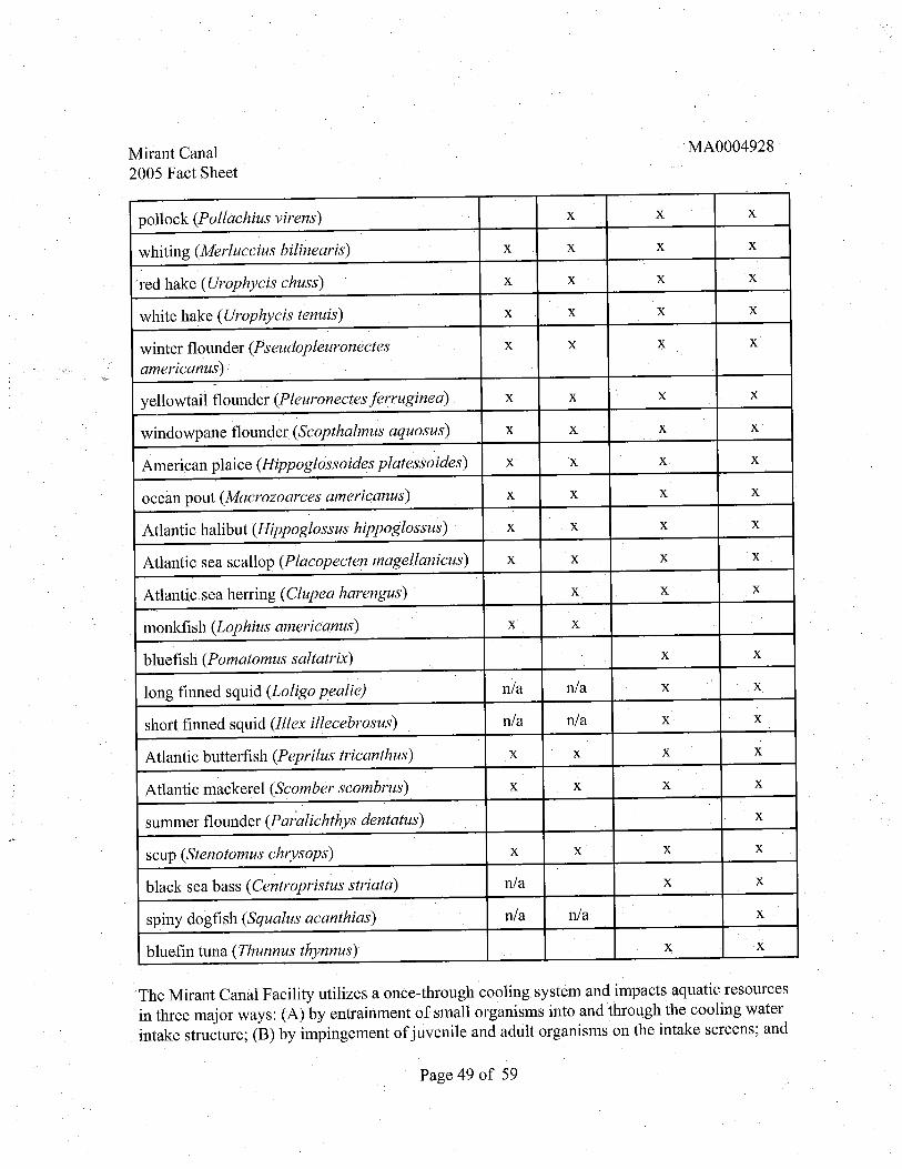
Mirant Canal2005 Fact Sheet
MA0004928
pollock (Pollachius vil'ens)
whiting (Merluccius bilinearis)
red hake (Urophycis chuss)
white hake (Urophycis tenuis)
winter flounder (Fseudopleuronectesamericanus)
yellowtail flounder (Pleuronectes ferruginea)
windowpane flounder (Scopthalmus aquosus)
American plaice (Hippoglossoides plates so ides)
ocean pout (Macrozoarces americ:anus)
Atlantic halibut (Hippoglossus hippoglossus)
Atlantic sea scallop (Placopecten magellanicus)
Atlantic. sea herring (Clupea harengus)
monkfish (Lophius americanus)
bluefish (Pomatomus saltatrix)
long finned squid (Loligo pealie) nla n/a
short finned squid (Ilex ilecebrosus) n/a n/a
Atlantic butterfish (Peprilus tricanthus)
Atlantic mackerel (Scomber scombrus)
summer flounder (Pm alichthys dentatus)
scup. (Stenotomus chrysops)
black sea bass (Centropristus striata) n/a
spiny dogfish (Squalus acanthias) n/a n/a
bluefin tuna (Thunnus thynnus)
The Mirant Canal Facility utilizes a once-through cooling system and impacts aquatic resourcesin three major ways: (A) by entrainment of small organisms into and through the cooling waterintake structure; (B) by impingement of juvenile and adult organisms on the intake screens; and
Page 49 of 59
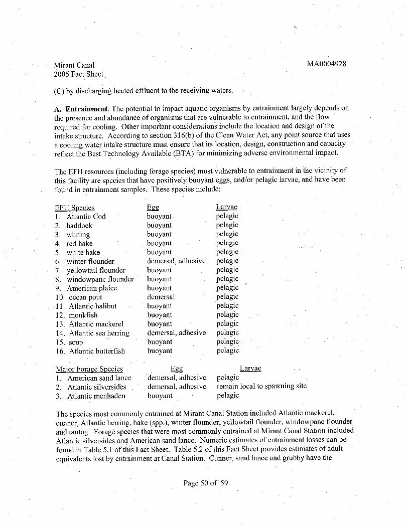
Mirant Canal2005 Fact Sheet
MA0004928
(C) by discharging heated effuent to the receiving waters.
A. Entrainment: The potential to impact aquatic organisms by entrainment largely depends onthe presence and abundance of organisms that are vulnerable to entrainment, and the flowrequired for cooling. Other important considerations include the location and design of theintake structure. According to section 316(b) of the Clean Water Act, any point source that usesa cooling water intake structure must ensure that its location, design, construction and capacityreflect the Best Technology Available (BT A) for minimizing adverse environmental impact.
TheEFH resources (including forage species) most vulnerable to entrainment in the vicinity ofthis facility are species that have positively buoyant eggs , andlor pelagic larvae, and have beenfound in entrainment samples. These species include:
EFH Species1. Atlantic Cod2. haddock
3. whiting
4. red hake
5. white hake
6. winter flounder
7. yellowtail flounder8. windowpane flounder9. American plaice10. ocean pout
11, Atlantic halibut
12. monkfish13. Atlantic mackerel14. Atlantic sea helTing
15. scup
16. Atlantic butterfish
Maior Forage Species1. American sand lance2. Atlantic silvers ides .3. Atlantic menhaden
buoyantbuoyantbuoyantbuoyantbuoyantdemersal, adhesivebuoyantbuoyantbuoyantdemersalbuoyantbuoyantbuoyantdemersal, adhesivebuoyantbuoyant
demersal , adhesivedemersal , adhesivebuoyant
Larvaepelagicpelagicpelagicpelagicpelagicpelagicpelagicpelagicpelagicpelagicpelagicpelagicpelagicpelagicpelagicpelagic
Larvaepelagicremain local to spawning sitepelagic
The species most commonly entrained at MirantCanal Station included Atlantic mackerelcunner, Atlantic helTing, hake (spp.), winter flounder, yellowtail flounder, windowpane flounderand tautog. Forage species that were most commonly entrained at Mirant Canal Station includedAtlantic silversides and American sand lance. Numeric estimates of entrainment losses can befound in Table 5. 1 of this Fact Sheet. Table 5.2 of this Fact Sheet provides estimates of adultequivalents lost by entrainment at Canal Station. Cunner, sand lance and grubby have the
Page 50 of 59

Mirant Canal2005 Fact Sheet
MA0004928
greatest loss of equivalent adults.
B. Impingement: Organisms that are of a size too large to pass through the intake screens aresWl vulnerable to being impinged on the screens. Additionally, the intake location and design
and cooling water flow requirements are major factors in assessing impingement potential.
EFH species considered to be most vulnerable to hann from impingement have one or more ofthe following characteristics: (A) pass intake structures in large, dense schools as juveniles or
adults; (B) are actively pursued as major forage species; (C) are attracted to the intake structureas a source of forage or refuge; (D) are slow moving or are otherwise unable to escape the intakecurrent; andlor (E) are structurally delicate, and likely to die if impinged. Of the EFH speciesand their forage previously listed, the following species have been impinged at Canal Station, or
are potentially vulnerable to impingement based on their characteristics as outlined above:
EFH Species1. Atlantic cod
2. pollock
3. red hake
4. white hake
5. winter flounder
6. yellowtail flounder7. windowpane flounder8. Atlantic sea herring9. Atlantic butterfish10. Atlantic mackerel11. scup
MaiorForage Species1. American sand lance2. Atlantic silversides
3. alewife
4. Atlantic menhaden
Vulnerable Lifestagejuvenile, adultjuvenile , adultjuvenile , adultjuvenile , adultjuvenile , adultjuvenile; adult
juvenile , adultjuvenile , adultjuvenile, adultjuvenile , adultjuvenile, adult
Vulnerable Lifestagejuvenile , adultjuvenile , adultjuvenile , adultjuvenile , adult
Species that were found to be most commonly impinged included Atlantic menhaden andAtlantic silversides , alewife and cunner. Estimates of impingement losses can be found in Table
3 of this Fact Sheet.
c. Discharge of Heated Effuent: The discharge of heated effuent may kil or impairorganisms directly, elicit changes in normal behavior (alter nonnal migration patterns , cause
avoidance of areas) or change norn1al trophic dynamics. The size and location of the thennalplume as well as the magnitude of the change over ambient temperatures (delta T) detennine thelevel of thermal impact.
Page 51 of 59

Mirant Canal2005 Fact Sheet
MA0004928
Cape Cod represents a biological breakpoint with different assemblages of species north andsouth of this peninsula. The species from the northern side of the Cape (Gulf of Maine) areprimarily cold water species , while those from the southern side (Buzzards Bay) are primarilywarm water species. The Cape Cod Canal gets a mix of species from both sides , some appearingonly seasonally, primarily in response to water temperature. Species that are found primarily inthe Gulf of Maine and are at their southern range of distribution would likely be at the greatestrisk for impacts due to the thennal discharge. Table 6.2 provides a brief compilation oftemperature preferences of the EFH species likely to be present in the Canal. This is not acomprehensive list, information is taken primarily from Collette and Klein-Macphee.
Table 6. Temperature Preferences . of EFH Species Likely to be Present in the CapeCod Canal
EFHSpecies Temperature Spawning temperature
range COC)
Atlantic cod (Gadus morhua) 0 to 13 5 to 7
haddock (Melanogrammus 2 to 16 5 to 6.
aeglejinus) 2 to 1 0 preferred
pollock (Pollachius virens) 0 to15 4.4 to 6.
whiting (Merluccius bilnearis) 7 to 1 7 no data available
red hake (Urophycis chuss) 5 to12 5 to 1 0
white hake (Urophycis tenuis) 0 to 13 no data available4 to 1 0 pre felTed
winter flounder 0 to 20 3 to 5.
(Pseudopleuronectesamericanus)
yellowtail flounder (Pleuronectes 1 to 18 5 to 8.
jerruginea)
windowpane flounder 0 to 26. 6 to 1 7
(Scopthalmus aquosus) 5 to 13. 5 majority of spawning
occurs
American plaice 1. 7 to 7 to 4.4(Hippoglossoides platessoides) 7 to 7.7 preferred
20 Collette , Band G. Klein-MacPhee (eds. ), 2002 , Bigelow and Schroeder s fishes of the
Gulf of Maine , Smithsonian Institution Press , Washington DC , p. 748.
Page 52 of 59

. Mirant Canal2005 Fact Sheet
MA0004928
ocean pout (Macrozoarces 0 to 16 no data available
american us 6 to 9 preferred
Atlanti halibut (Hippoglossus 6 to 15 no data available
hippoglossus) 3 to 9 preferred
monkfish (Lophius american us) Oto 24 no data available
Atlantic sea herring (Clupea 4 to 16 1 0 to
harengus) 5 to 9 pre felTed
bluefish (Pomatomus saltatrix) 11. 8 to 30.4 18 to 25
Atlantic butterfish (peprilus 4.4 to 21.6 l5 to 20tricanthus)
Atlantic mackerel (Scomber 6 to 20 9 to 14
scombrus)
black sea bass ( Centropristus 6to 29. no data available
striata)
Based on the thermal monitoring and hydrodynamic modeling as discussedinSection 5.1 of this
Fact Sheet and the temperature tolerance data for the relevant EFH species , EP A does not
believe that significant impacts will occur to essential fish habitat.
EP A does not believe that essential fish habitat is being significantly impacted by the thennaldischarge. EP A is concerned about the entrainment and impingement losses , as a result a
thorough review of technological changes at the station was conducted. EP A detennined that the
steps outlined in Section 5.2.4 of this Fact Sheet should be taken to minimize entrainment andimpingement mortality under CW A g 316(b). These steps have been incorporated intO'the Draft
Pennit at Section LA. 13.
As the federal agency charged with authorizing the discharge from this facility, EP A is
consulting with the NMFS under section 305 (b)(2) of the Magnuson-Stevens Act for EFH. Asmentioned above a number of EFH species have been entrained andlor impinged by CanalStation. This consultation wil be completed before the pennit is finalized.
Endangered Species Act (ESA)
The U.S. Environmental Protection Agency - Region I, New England (EPA) is preparing toreissue the National Pollutant Discharge Elimination System (NPDES) pennit to the MirantCanal, LLC Station in Sandwich, Massachusetts , located on the southern shore of the Cape CodCanal , about 1 500 yards from the eastern exit to Cape Cod Bay. The NPDES pennit authorizes
Page 53 of 59

Mirant Canal2005 Fact Sheet
MA0004928
the withdrawal of water from and the discharge of heated effuent into the Cape Cod Canal thatconnects Cape Cod Bay and Buzzards Bay. Adetailed description of the Facility and the localenvironment may be fouhd in the October 30 , 2003 , Mirant Canal , LLC NPDES PermitApplication (MA0004928) and in Section 4.2 of this Fact Sheet.
As the federal agency charged with authorizing the discharge from this facility, EP A , as part its consultation responsibilities under section 7 (a)(2) of the Endangered Species Act (ESA) forpotential impacts to federally listed species, is seeking written concurrence from the NationalOceanic and AtmosphericAdministration, National Marine Fisheries Service (NOAA Fisheries)on this detern1ination. In this particular case , several endangered species under the jurisdictionof NOAA Fisheries may potentially be affected by the reissuance. It is EP A' s opinion, however
that the location and operation of this facility, as governed by the Draft Pennit, are not likely toadversely affect the species of concern.
The marine species shown in Table 7. 1 are listed as threatened Qr endangered and may be foundin the vicinity of this facility. In making its assessment, EPA has consulted general profiles anddescriptions of these species found in the following sources:
1. NOAA Fisheries , 2005. http://www.nmfs.noaa. gov/pr/species/turtles/#species NationalMarine Fisheries Service.
2. CCCSTSL 2005. http://www.cccturtle.org/contents.htm. Caribbean Conservation
Corporation & Sea Turtle Survival League.
Table 7. Endangered/Threatened Marine Mammal Species Found in the Vicinity ofMirant Canal Station
Marine Mammal Species Threatened or Endangered
Loggerhead Turtle Caretta caretta Threatened
Kemp s Ridley Turtle Leipdochelys kempii Endangered
Hawksbil Turtle Eretmochelys imbricata Endangered
Page 54 of 59

Mirant Canal2005 Fact Sheet
MA0004928
Leatherback Turtle De1'nochelys coriacea Endangered
Green Turtle Chelonia mydas Endangered/Threatened
Northern Right Whale Eubalaena glacialis Endangered
Humpback Whale megaptera novaeangliae Endangered
Marine Turtles
Loggerhead (Caretta caretta)
(Threatened): Listed as threatened since 1978 , this speciesis more abundant inUnited States coastal waters than any other marine turtle, pre felTing bayscontinental shelves and estuarine habitats. Sexual maturity occurs between 16-years and individuals may take up to thirt years to mature. Mating occurs fromlate March through early June, and eggs may be laid throughout the summer.Nesting occurs during the summer in lower latitudes (NOAA Fisheries). The dietof this turtle consists mainly of mollusks , jellyfish, shrimp and crabs (CCCSTSL).The mortality rate of these turtles is approximately 2% from being caught inpower plant intake systems (NOAA Fisheries).
Kemp s Ridley (Levidochelvs kemvii
(Endangered): Listed as endangered since 1970 , this species occurs in thenorthwestern Atlantic along shallow coastal areas with sandy or muddy bottoms.Sexual maturity is thought to occur between 7- 15 years in this species , thesmallest of all marine turtles (NOAA Fisheries). Annual nesting occurs usuallytwic per season as a mass synchronized event along the Northeast coast ofMexico. The diet of this turtle consists of clams , shrimp, fish, squid, jellyfishcrabs , mussels and sea urchins. Potential threats to this species include habitatdegradation and entanglement from floating debris (CCCSTSL).
Hawksbil (Eretmochelvs imbricata)
(Endangered): Listed as endangered since 1970 , this species occurs in tropicaland subtropical areas of the Atlantic Ocean, but may be found in coastal areasnorth to Massachusetts , in rocky areas , reefs and in both low and high energyareas. Nesting occurs in a variety of habitats usually under some vegetation andmay occur in intervals of 2-4 years. The age at which this species is consideredsexually mature is unkown (NOAA Fisheries). These turtles usually feed onsquid, shrimp, sponges and anemones (CCCSTSL). Potential threats to this
Page 55 of 59

Mirant Canal2005 Fact Sheet
MA0004928
species include coastal pollution and these turtles are known to be caught in,cooling water intake structures of coastal facilities (NOAA Fisheries).
Leatherback (Dermochelvs coriacea)
(Endangered): Listed as endangered since 1970 , this primarily pelagic species islarger and more widely distributed than any other species of marine turtle.Although nesting does not occur often in U.S. coastal waters , this species isknown to feed in offshore areas primarily on jellyfish (CCCSTSL). During thesummer, this species maybe found in coastal areas from Florida to the Gulf ofMaine. Floating debris is one of the primary threats to these turtles (NOAAFisheries ).
Green (Chelonia mvdas)
(Endangered/Threatened): Listed as endangered for breeding populations offof the Pacific coast of Mexico and Florida in 1978 , these turtles range fromtemperate to tropical waters , and may be found in coastal areas with sea grassbeds , protected shores , bays and around islands. Age at sexualniatirity is
thoughtto be between 20-50 years with intervals of2-4 years between nesting periods(NOAA Fisheries). As juveniles , the diet of these turtles consists of aquaticinsects , algae , crustaceans and wonns. As adults , these turtles are herbivorouseating only algae and sea grasses (CCCSTSL). Potential threats to this turtleinclude coastal pollution and becoming caught in cooling water intake structuresof coastal power plants , with the mortality estimate of 7% (NOAA Fisheries).
Cetaceans
Northern Right Whale (Eubalaena glacialis)
(Endangered): Listed as endangered in 1970 , this species is amongthe rarest of the large whales , with only a few hundred left in the North Atlanticpopulations. .In general, these whales may be found in coastal or continental shelfwaters. However, their distribution is based upon the distribution of their prey.Age at sexual maturity is usually between 9- 10 years , and reproduction mayoccur at intervals of every 3-6 years. Calving takes place during the winterseason in the coastal areas of Southeastern U.S. Nursery and feeding groundsinclude coastal areas of New England up to the Bay of Fundy during the summerseason. In 1991 , the U.S. National Marine Fisheries Service (NMFS) identifiedkey habitats , or areas of "High Use " one of which is Cape Cod BaylMassachusetts Bay. In 1994 , these areas were designatedby NMFS as Critical
Page 56 of 59

Mirant Canal2005 Fact Sheet
MA0004928
Habitat for the Western North Atlantic population. Potential threats to thisspecies included habitat degradation and pollution (NOAA Fisheries).
Humpback Whale (Me,?avtera novaean,?liae)
(Endangered): Listed as endangered in 1970 , this species is widely distributedin the world' s oceans among four different stocks , one of which is the Gulfof Maine stock. These whales inhabit coastal embayments during thesummer but are generally found in waters over continental shelves. Similar toNorthern Right Whales, the humpback whales migrate to lower latitudes duringthe winter for breeding season, and return to higher latitudes for the summerfeeding season. Age at sexual maturity is between 4-6 years oldwithreproduction occurring at intervals of every 2-3 years. Humpback whales feed onsmall schooling fishes including mackerel , haddock, sand lance and herring, aswell as zooplankton. Potential impacts from coastal development and pollutioninclude degraded habitat, resulting in the limitation of habitat necessary forsurvival and reproduction (NOAA Fisheries).
As previously discussed, the Cape Cod Canal is a cham1el that connects Cape Cod Bay toBuzzards Bay and may be used for transport by various species of marine organisms , includingsea turtles ' seals and other marine mammals.' Coastal power plants and other industrial facilitiesare known to have an adverse impact on marine organisms by impingement or entrainnwnt incooling water intake structures. '
In the case of Mirant Canal Station, the potential impact of facility operation on marine turtlesand marine mammals has been minimal historically, with the last sighting of a marine turtle inthe vicinity of the intake structure having occulTed in 1977;
Although the intake structures are wide eno'Qgh to accommodate sea turtles and many marinemammals, the ability of these organisms to swim away and escape impingement prevents injury.In addition, although heated water is discharged from this facility, the flow of the Cape CodCanal in conjunction with a submerged diffuser provides for rapid mixing of heated effuent andtherefore , reduces the adverse impact of heat stress to these organisms , as well as reducing thelikelihood of the thennal discharge providing a dangerous attractant.
EP A has. included in the Draft Pennit a requirement for the facility to develop a plan to monitorand report any marine turtles or marine mammals sighted in close proximity to the facility and itsintake structures. In addition, it also requires that a response protocol be designed as a
\ precaution for any impingement of these organisms that may occur in the future.
Based upon the factors outlined above , EP A believes that there will be no significant adverseenvironmental impact to the endangered species that migrate through or inhabit areas in the
Page 57 of 59

Mirant Canal2005 Fact Sheet
MA0004928
vicinity of Mirant Canal Station. Furthennore, the Draft Pennit provides a means to monitor forthe presence of marine turtles and marine mammals that may be susceptible to adverse impactfrom this facility. Therefore, EP A believes that thispennit action does not walTant a fonnalconsultation under section 7 of theE SA. EPA will engage in informal consultation with NOAAFisheries to determine whether formal consultation wil be needed.
Monitoring Frequency
The effuent monitoring requirements have been established to yield data representative of thedischarge under authority of Section 308(a) of the CWA as required by 40 C.F.R. 122.41 (j),
122.41 (j(4), (5), 122.44 and 122.48.
State Certifcation Requirements
EP A may not issue a pennit in the Commonwealth of Massachusetts unless the MassachusettsDepartment of Environmental Protection (MA DEP) either certifies that limits contained in thepennit are stringent enough to assure that pollutant discharges and cooling water withdrawalswil not result in violations of the State s Water Quality Standards or waives this certification.The staff of the MA DEP has reviewed the Draft Permit. , EP A has requested permit certificationby the state pursuant to 40 C.F.R. 124.53 and expects that the Draft Permit wil be certified.
10. General Conditions and Definitions
The remaining general and special conditions of the permit are based on the NPDES regulations40 C.F.R. Parts 122 through 125 , and consist primarily of management requirements common toall pennits. 11.0 Comment Period, Hearing Requests, and Procedures for Final Decisions
All persons , including applicants, who believe any condition of the Draft Permit is inappropriatemust raise all issues and submit all available arguments and all supporting material for theirarguments in full by the close of the public comment period, to the U.S. EP A, Offce ofEcosystem Protection, Massachusetts State Program Unit, 1 Congress Street, Suite 1100 , BostonMassachusetts 02114-2023 . Any person, prior to such date , may submit a request in writing fora public hearing to consider the Draft Pennit to EP A and the State Agency. Such requests shallstate the nature of the issues proposed to be raised in the hearing. A public meeting may be heldif the criteria stated in 40 C. R. g 124.12 are satisfied. In reaching a final decision on the DraftPerh1it, the EPA wil respond to all significant comments and make these responses available tothe public at EP A's Boston offce.
Following the close ofthe comment period, and after any public hearings , if such hearings areheld, the EP A wil issue a Final Pennit decision and forward a copy of the final decision to the
Page 58 of 59

, '
Mirant Canal2005 Fact Sheet
MA0004928
applicant and each person who has submitted written comments or requested notice. Within 30days following the notice of the Final Permit decision, any interested person may submit apetition for review of the pennit to EPA' s Environmental Appeals Board consistent with 40
R. g 124. 19.
12.0 . EP A Contact
Additional infonnation concerning the Draft Pennit maybe obtained between the hours of9:00A.M. and5:00 P.M. (8:45 A.M. and 5:00 P.M. for the state), Monday through Friday, excludingholidays from:
Ms. Sharon Zaya, Environmental Engineer,S. Environmental Protection AgencyOffce of Ecosystem Protection
1 Congress Street, Suite 1100 (CIP)Boston, Massachusetts 02114-2023
Telephone: (617) 918- 1995 FAX No. : (617) 918-0995
Paul Hogan, Environmental EngineerMassachusetts Department of Environmental Protection
Division Of Watershed Management Surface Water Discharge Permit Program
627 Main Street, 2 FloorWorcester, Massachusetts 01608
Telephone: (508) 767-2796
Linda M. Murphy, DirectorOffce of Ecosystem Protection
S. Environmental Protection AgencyDate:
Page 59 of 59
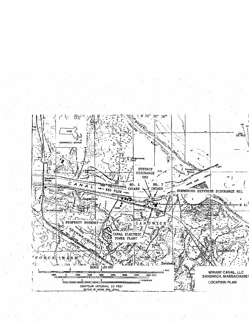
...