miqp-based layout design for building...
TRANSCRIPT
EUROGRAPHICS 2018 / D. Gutierrez and A. Sheffer(Guest Editors)
Volume 37 (2018), Number 2
MIQP-based Layout Design for Building Interiors
Wenming Wu1,2 Lubin Fan2 Ligang Liu1 Peter Wonka2
1University of Science and Technology of China, China2King Abdullah University of Science & Technology, Saudi Arabia
Floorplans 3D Rendering
1st floor
2nd floor
1st floor 2nd floor
(a) (b)
Floorplan 3D Rendering5m
Foyer2.80 x 2.45
Kitchen3.50 x 2.45
Living2.80 x 3.85
Dining3.85 x 2.80
Corridor1.40 x 3.50
Bedroom12.15 x 2.45
M. Bedroom4.90 x 2.45
Corridor2.50 x 1.40
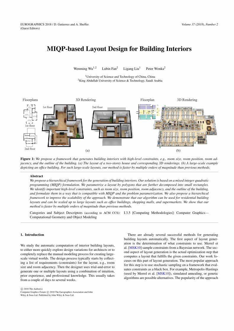
Figure 1: We propose a framework that generates building interiors with high-level constraints, e.g., room size, room position, room ad-jacency, and the outline of the building. (a) The layout of a two-storey house and corresponding 3D renderings. (b) A large-scale exampledepicting an office building. For such large-scale layouts, our method is faster by multiple orders of magnitude than previous methods.
AbstractWe propose a hierarchical framework for the generation of building interiors. Our solution is based on a mixed integer quadraticprogramming (MIQP) formulation. We parametrize a layout by polygons that are further decomposed into small rectangles.We identify important high-level constraints, such as room size, room position, room adjacency, and the outline of the building,and formulate them in a way that is compatible with MIQP and the problem parametrization. We also propose a hierarchicalframework to improve the scalability of the approach. We demonstrate that our algorithm can be used for residential buildinglayouts and can be scaled up to large layouts such as office buildings, shopping malls, and supermarkets. We show that ourmethod is faster by multiple orders of magnitude than previous methods.
Categories and Subject Descriptors (according to ACM CCS): I.3.5 [Computing Methodologies]: Computer Graphics—Computational Geometry and Object Modeling
1. Introduction
We study the automatic computation of interior building layouts,to either more quickly explore design variations for architects or tocompletely replace the manual modeling process for creating large-scale virtual worlds. The design process typically starts by collect-ing a list of requirements (constraints) for the layout, e.g., roomsize and room adjacency. Then the designer uses trial-and-error togenerate one or multiple layouts using a combination of intuition,prior experience, and professional knowledge. This usually takesfrom a couple of days to several weeks.
There are already several successful methods for generatingbuilding layouts automatically. The first aspect of layout gener-ation is the determination of what constraints to use. Merrel etal. [MSK10] sample constraints from a Bayesian network. The sec-ond aspect of layout generation is the actual optimization step thatcomputes a layout that fulfills the given constraints. Our work fo-cuses on this part of layout generation. The most popular approachfor this step is to use stochastic sampling on a framework that eval-uates constraints as a black box. For example, Metropolis-Hastings(used by Merrel et al. [MSK10]), simulated annealing, or geneticalgorithms are possible alternatives. The popularity of the approach
c© 2018 The Author(s)Computer Graphics Forum c© 2018 The Eurographics Association and JohnWiley & Sons Ltd. Published by John Wiley & Sons Ltd.
Wu et al. / MIQP-based Layout Design for Building Interiors
Level 1 Level 2 Floorplan 3D renderingInputSize range constraints: [1,6]
Boundary constraints* Foyer
Adjacency constrains* Kitchen - Living room* Foyer - Living room* Bedroom - living room* Bedroom - bath
Aspect ratio: [1,2]
Size target:* Foyer: (2.03, 2.92)* Kitchen: (3.28, 2.26)* Living room: (3.85, 5.65)* Bedroom: (3.20, 4.42) * Bath room: (1.88, 2.35)
Kitchen
LivingRoom
Bedroom
Bath Foyer
Kitchen1.75 x 2.50
LivingRoom
1.75 x 2.50
Foye
r2.
25 x
1.5
0
Bat
h2.
25 x
1.7
5
Bedroom1.75 x 2.50
Kitchen
LivingRoom
Foyer
Bedroom
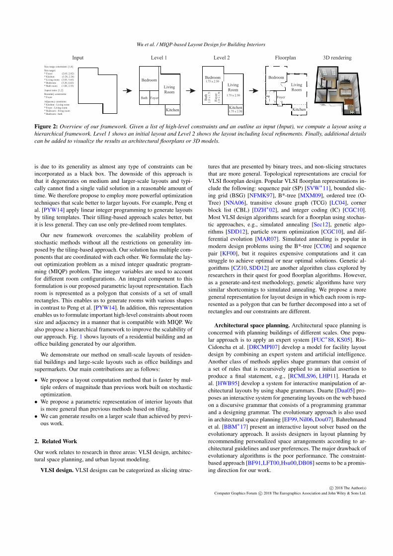
Figure 2: Overview of our framework. Given a list of high-level constraints and an outline as input (Input), we compute a layout using ahierarchical framework. Level 1 shows an initial layout and Level 2 shows the layout including local refinements. Finally, additional detailscan be added to visualize the results as architectural floorplans or 3D models.
is due to its generality as almost any type of constraints can beincorporated as a black box. The downside of this approach isthat it degenerates on medium and larger-scale layouts and typi-cally cannot find a single valid solution in a reasonable amount oftime. We therefore propose to employ more powerful optimizationtechniques that scale better to larger layouts. For example, Peng etal. [PYW14] apply linear integer programming to generate layoutsby tiling templates. Their tilling-based approach scales better, butit is less general. They can use only pre-defined room templates.
Our new framework overcomes the scalability problem ofstochastic methods without all the restrictions on generality im-posed by the tiling-based approach. Our solution has multiple com-ponents that are coordinated with each other. We formulate the lay-out optimization problem as a mixed integer quadratic program-ming (MIQP) problem. The integer variables are used to accountfor different room configurations. An integral component to thisformulation is our proposed parametric layout representation. Eachroom is represented as a polygon that consists of a set of smallrectangles. This enables us to generate rooms with various shapesin contrast to Peng et al. [PYW14]. In addition, this representationenables us to formulate important high-level constraints about roomsize and adjacency in a manner that is compatible with MIQP. Wealso propose a hierarchical framework to improve the scalability ofour approach. Fig. 1 shows layouts of a residential building and anoffice building generated by our algorithm.
We demonstrate our method on small-scale layouts of residen-tial buildings and large-scale layouts such as office buildings andsupermarkets. Our main contributions are as follows:
• We propose a layout computation method that is faster by mul-tiple orders of magnitude than previous work built on stochasticoptimization.• We propose a parametric representation of interior layouts that
is more general than previous methods based on tiling.• We can generate results on a larger scale than achieved by previ-
ous work.
2. Related Work
Our work relates to research in three areas: VLSI design, architec-tural space planning, and urban layout modeling.
VLSI design. VLSI designs can be categorized as slicing struc-
tures that are presented by binary trees, and non-slicing structuresthat are more general. Topological representations are crucial forVLSI floorplan design. Popular VLSI floorplan representations in-clude the following: sequence pair (SP) [SVW∗11], bounded slic-ing grid (BSG) [NFMK97], B*-tree [MXM09], ordered tree (O-Tree) [NNA06], transitive closure graph (TCG) [LC04], cornerblock list (CBL) [DZH∗02], and integer coding (IC) [CGC10].Most VLSI design algorithms search for a floorplan using stochas-tic approaches, e.g., simulated annealing [Sec12], genetic algo-rithms [SDD12], particle swarm optimization [CGC10], and dif-ferential evolution [MAR07]. Simulated annealing is popular inmodern design problems using the B*-tree [CC06] and sequencepair [KF00], but it requires expensive computations and it canstruggle to achieve optimal or near optimal solutions. Genetic al-gorithms [CZ10, SDD12] are another algorithm class explored byresearchers in their quest for good floorplan algorithms. However,as a generate-and-test methodology, genetic algorithms have verysimilar shortcomings to simulated annealing. We propose a moregeneral representation for layout design in which each room is rep-resented as a polygon that can be further decomposed into a set ofrectangles and our constraints are different.
Architectural space planning. Architectural space planning isconcerned with planning buildings of different scales. One popu-lar approach is to apply an expert system [FUC∗88, KS05]. Río-Cidoncha et al. [DRCMPI07] develop a model for facility layoutdesign by combining an expert system and artificial intelligence.Another class of methods applies shape grammars that consist ofa set of rules that is recursively applied to an initial assertion toproduce a final statement, e.g., [RCMLS96, LHP11]. Harada etal. [HWB95] develop a system for interactive manipulation of ar-chitectural layouts by using shape grammars. Duarte [Dua05] pro-poses an interactive system for generating layouts on the web basedon a discursive grammar that consists of a programming grammarand a designing grammar. The evolutionary approach is also usedin architectural space planning [EF99,Nil06,Dou07]. Bahrehmandet al. [BBM∗17] present an interactive layout solver based on theevolutionary approach. It assists designers in layout planning byrecommending personalized space arrangements according to ar-chitectural guidelines and user preferences. The major drawback ofevolutionary algorithms is the poor performance. The constraint-based approach [BF91,LFT00,Hsu00,DB08] seems to be a promis-ing direction for our work.
c© 2018 The Author(s)Computer Graphics Forum c© 2018 The Eurographics Association and John Wiley & Sons Ltd.
Wu et al. / MIQP-based Layout Design for Building Interiors
Merrel et al. [MSK10] learn attributes of rooms from a givendataset by a Bayesian network and synthesize the layout by thestochastic method. The main problem of the approach is thatit is not suitable for large-scale examples due to the stochas-tic method. Rosser et al. [RSM17] also propose a data-drivenmethod. They learn building measurements to produce interiorplans. In [LYAM13], the authors present an interactive system tocreate interior room layouts subject to design constraints, user pref-erences, and manufacturing considerations. Hua et al. [Hua16] de-velop a method for automatically constructing irregular floor plans.Given image patterns, the program produces a variety of layoutsthat satisfy both geometric and topological requirements. Bao etal. [BYMW] propose a method to explore building layouts. To ob-tain variations in connectivity, they use standard simulated anneal-ing. Liu et al. [LWKF17] apply integer programming to encodehigh-level constraints. However, their goal is to evaluate the ex-tracted constraints in recovering the floorplan data from a rasterimage.
Urban layout modeling. Our problem also relates to urban lay-out modeling. [Ali12, STBB14] review the topic in a broad con-text. One common approach generates large-scale layouts by firstcreating the road network and then by generating parcels. An in-teractive example-based system for synthesizing urban layouts isproposed by [AVB08]. They use the structure and image data ofreal-world urban areas for complex urban layout generation. Net-work design can be seen as a dual problem in layout design. Chenet al. [CEW∗08] create road networks from an existing street net-work by designing an underlying tensor field and editing the graphrepresentation. Yang et al. [YWVW13] combine hierarchical split-ting and global optimization to guarantee the fairness and regularityof the generated streets and parcels. Improving upon this previouswork, Peng et al. [PYW14] propose a novel tiling-based approachwith deformable templates. Their subsequent work [PYB∗16] pro-poses an integer-programming-based approach to generate net-works starting from functional specifications. Feng et al. [FYY∗16]focus on mid-scale layout modeling based on human crowds. Givena layout domain, their approach synthesizes crowd-aware layoutsby considering the crowd flow. Urban layout modeling has alsobeen widely used in the design of video game environments. Maet al. [MVLS14] propose an algorithmic approach for automati-cally laying out complex game levels that conform to the designer’sspecifications.
3. Overview
Our framework consists of the following components:
– First, we introduce a parametric representation that describes alayout by a set of axis-aligned polygons. To make the model bet-ter suitable for optimization, we also present a rectangle-basedlayout representation (Section 4).
– Second, we describe the basic formulation of our MIQP-basedmethod (Section 5.1).
– Third, we describe a set of high-level constraints for layout gen-eration (Section 5.2).
– Fourth, we propose a hierarchical framework to extend the basicmethod (Section 5.3).
Bedroom
Bedroom
Obstacle
w
d
Living Room
Living Room
Bathroom
KitchenKitchen
Living Room
Bedroom
Bathroom
Bedroom
(x ,y ,w ,d ,l )i i i i i
r1
r2 r3
r4 r5
r6
Bedroom
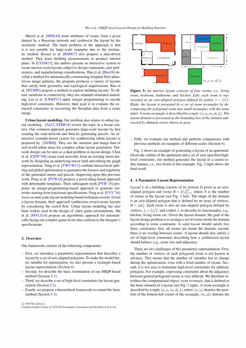
Figure 3: An interior layout consists of four rooms, i.e., livingroom, bedroom, bathroom, and kitchen. Left: each room is rep-resented as an axis-aligned polygon defined by points, r = {ri}.Right: the layout is presented by a set of room rectangles by de-composing the polygonal room into small rectangles with the samelabel. A room rectangle is described by a tuple (xi,yi,wi,di, li). Thelayout domain is presented as the bounding box of the domain sub-tracted by obstacle rooms shown in gray.
– Fifth, we evaluate our method and perform comparisons withprevious methods on examples of different scales (Section 6).
Fig. 2 shows an example of generating a layout of an apartment.Given the outline of the apartment and a set of user-specified high-level constraints, our method generates the layout in a coarse-to-fine manner, i.e., two levels in this example. Fig. 2 right shows thefinal result.
4. A Parametric Layout Representation
Layout L of a building consists of its domain D given as an axis-aligned polygon and rooms R = {ri}N
i=1, where N is the numberof rooms in the layout (see Fig. 3 left). The shape of the domainis an axis-aligned polygon that is defined by an array of vertices,D = {di}. Each room is also an axis-aligned polygon defined byvertices, ri = {r j
i }, and a label, l, to describe its functionality, e.g.,kitchen, living room, etc. Given the layout domain, the goal of thelayout design problem is to arrange a set of rooms inside the domainaccording to some constraints. A valid layout should satisfy twobasic constraints: first, all rooms are inside the domain; second,there is no overlap between rooms. A layout should also satisfy aset of high-level constraints describing how a synthesized layoutshould behave, e.g., room size and adjacency.
There are two challenges of this parametric representation. First,the number of vertices of each polygonal room is not known inadvance. This means that the number of variables has to changeduring the optimization, even with a fixed number of rooms. Sec-ond, it is not easy to formulate high-level constraints for arbitrarypolygons. For example, expressing constraints about the adjacencybetween general polygonal rooms is very difficult. We therefore in-troduce the computational object, room rectangle, that is defined asthe basic element of a layout (see Fig. 3 right). A room rectangle isdescribed by a tuple (xi,yi,wi,di, li) where (xi,yi) denotes the posi-tion of the bottom-left corner of the rectangle, (wi,di) denotes the
c© 2018 The Author(s)Computer Graphics Forum c© 2018 The Eurographics Association and John Wiley & Sons Ltd.
Wu et al. / MIQP-based Layout Design for Building Interiors
(a) (b)
Kitchen3.00 x 2.25
Living & dining4.75 x 3.75
Bedroom2.75 x 4.25
Living Room3.50 x 2.80
Bedroom 13.50 x 2.45
Kitchen2.10 x 2.80
S. Room2.10 x 2.80
M. Bedroom3.85 x 3.85
Dining2.80 x 2.45
Bedroom 23.15 x 2.10
Study2.80 x 3.50
Foyer2.10 x 3.85
Corridor3.15 x 1.05
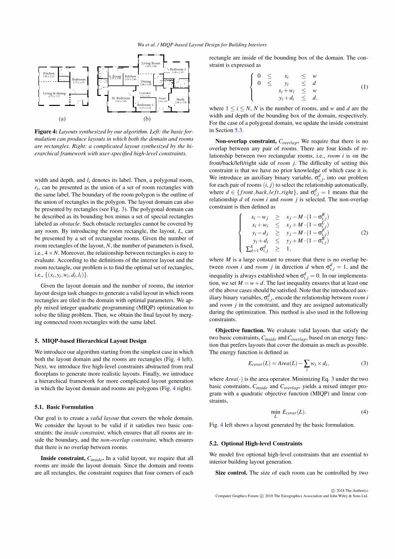
Figure 4: Layouts synthesized by our algorithm. Left: the basic for-mulation can produce layouts in which both the domain and roomsare rectangles. Right: a complicated layout synthesized by the hi-erarchical framework with user-specified high-level constraints.
width and depth, and li denotes its label. Then, a polygonal room,ri, can be presented as the union of a set of room rectangles withthe same label. The boundary of the room polygon is the outline ofthe union of rectangles in the polygon. The layout domain can alsobe presented by rectangles (see Fig. 3). The polygonal domain canbe described as its bounding box minus a set of special rectangleslabeled as obstacle. Such obstacle rectangles cannot be covered byany room. By introducing the room rectangle, the layout, L, canbe presented by a set of rectangular rooms. Given the number ofroom rectangles of the layout, N, the number of parameters is fixed,i.e., 4×N. Moreover, the relationship between rectangles is easy toevaluate. According to the definitions of the interior layout and theroom rectangle, our problem is to find the optimal set of rectangles,i.e., {(xi,yi,wi,di, li)}.
Given the layout domain and the number of rooms, the interiorlayout design task changes to generate a valid layout in which roomrectangles are tiled in the domain with optimal parameters. We ap-ply mixed integer quadratic programming (MIQP) optimization tosolve the tiling problem. Then, we obtain the final layout by merg-ing connected room rectangles with the same label.
5. MIQP-based Hierarchical Layout Design
We introduce our algorithm starting from the simplest case in whichboth the layout domain and the rooms are rectangles (Fig. 4 left).Next, we introduce five high-level constraints abstracted from realfloorplans to generate more realistic layouts. Finally, we introducea hierarchical framework for more complicated layout generationin which the layout domain and rooms are polygons (Fig. 4 right).
5.1. Basic Formulation
Our goal is to create a valid layout that covers the whole domain.We consider the layout to be valid if it satisfies two basic con-straints: the inside constraint, which ensures that all rooms are in-side the boundary, and the non-overlap constraint, which ensuresthat there is no overlap between rooms.
Inside constraint, Cinside. In a valid layout, we require that allrooms are inside the layout domain. Since the domain and roomsare all rectangles, the constraint requires that four corners of each
rectangle are inside of the bounding box of the domain. The con-straint is expressed as
0 ≤ xi ≤ w0 ≤ yi ≤ d
xi +wi ≤ wyi +di ≤ d,
(1)
where 1 ≤ i ≤ N, N is the number of rooms, and w and d are thewidth and depth of the bounding box of the domain, respectively.For the case of a polygonal domain, we update the inside constraintin Section 5.3.
Non-overlap constraint, Coverlap. We require that there is nooverlap between any pair of rooms. There are four kinds of re-lationship between two rectangular rooms, i.e., room i is on thefront/back/left/right side of room j. The difficulty of setting thisconstraint is that we have no prior knowledge of which case it is.We introduce an auxiliary binary variable, σ
di, j, into our problem
for each pair of rooms (i, j) to select the relationship automatically,where d ∈ { f ront,back, le f t,right}, and σ
di, j = 1 means that the
relationship d of room i and room j is selected. The non-overlapconstraint is then defined as
xi−w j ≥ x j−M · (1−σRi, j)
xi +wi ≤ x j +M · (1−σLi, j)
yi−d j ≥ y j−M · (1−σFi, j)
yi +di ≤ y j +M · (1−σBi, j)
∑4d=1 σ
di, j ≥ 1,
(2)
where M is a large constant to ensure that there is no overlap be-tween room i and room j in direction d when σ
di, j = 1, and the
inequality is always established when σdi, j = 0. In our implementa-
tion, we set M = w+d. The last inequality ensures that at least oneof the above cases should be satisfied. Note that the introduced aux-iliary binary variables, σ
di, j , encode the relationship between room i
and room j in the constraint, and they are assigned automaticallyduring the optimization. This method is also used in the followingconstraints.
Objective function. We evaluate valid layouts that satisfy thetwo basic constraints, Cinside and Coverlap, based on an energy func-tion that prefers layouts that cover the domain as much as possible.The energy function is defined as
Ecover(L) = Area(L)−∑i
wi×di, (3)
where Area(·) is the area operator. Minimizing Eq. 3 under the twobasic constraints, Cinside and Coverlap, yields a mixed integer pro-gram with a quadratic objective function (MIQP) and linear con-straints,
minL
Ecover(L). (4)
Fig. 4 left shows a layout generated by the basic formulation.
5.2. Optional High-level Constraints
We model five optional high-level constraints that are essential tointerior building layout generation.
Size control. The size of each room can be controlled by two
c© 2018 The Author(s)Computer Graphics Forum c© 2018 The Eurographics Association and John Wiley & Sons Ltd.
Wu et al. / MIQP-based Layout Design for Building Interiors
approaches: adding size range constraints for rooms and specify-ing target sizes for rooms. The range of the room size can be con-strained by providing the minimum and maximum values of wi anddi. Then, the size range constraint, Csize, is defined as{
wi ≤ wi ≤ widi ≤ di ≤ di,
(5)
where (wi,di) and (wi,di) are the minimum and maximum sizesof room i, respectively. The user can also specify target sizes forrooms. Then, the size error of rooms can be evaluated by a sizeerror term, which is defined as
Esize = ∑i(wi−w∗i )
2 +(di−d∗i )2, (6)
where (w∗i ,d∗i ) is the target size of room i. We can encourage room
sizes to become close to the user-specified values by adding Esizeto the objective function.
Aspect ratio constraint, Cratio. We provide a room aspect ratioconstraint, Cratio, to avoid generating rooms that are too wide or toonarrow. Similar to Coverlap, we add an auxiliary binary variable foreach room to adjust the orientation (i.e., horizontal and vertical) ofthe room rectangle. The aspect ratio constraint is defined as
ri ·di ≤ wi +M ·σiri ·di ≥ wi−M ·σiri ·wi ≤ di +M · (1−σi)ri ·wi ≥ di−M · (1−σi),
(7)
where (ri,ri) are the minimum and maximum aspect ratios betweenwi and di of room i, and ri ≥ 1. σi = 0 means that room i is ahorizontal room and its aspect ratio is in the range of [ri,ri]. σi = 1means that room i is a vertical room.
Position constraint, Cpos. During the design process, sometimesthe designer has to specify the approximate position for a room,e.g., the foyer should connect to the main door. A guide positionfor a room is presented as a single point (x∗,y∗) or two points. Foreach point, the position constraint requires the room to cover thepoint: {
xi ≤ x∗ ≤ xi +wiyi ≤ y∗ ≤ yi +di.
(8)
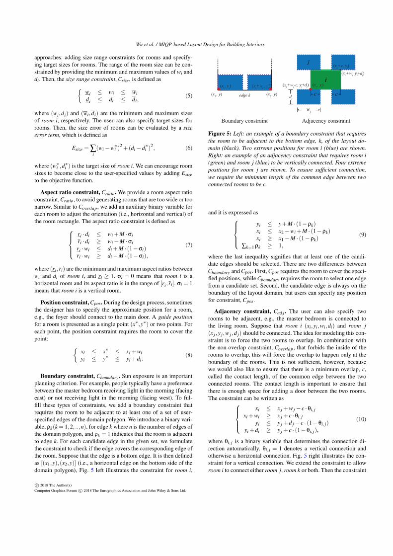
Boundary constraint, Cboundary. Sun exposure is an importantplanning criterion. For example, people typically have a preferencebetween the master bedroom receiving light in the morning (facingeast) or not receiving light in the morning (facing west). To ful-fill these types of constraints, we add a boundary constraint thatrequires the room to be adjacent to at least one of a set of user-specified edges of the domain polygon. We introduce a binary vari-able, ρk(k = 1,2, ..,n), for edge k where n is the number of edges ofthe domain polygon, and ρk = 1 indicates that the room is adjacentto edge k. For each candidate edge in the given set, we formulatethe constraint to check if the edge covers the corresponding edge ofthe room. Suppose that the edge is a bottom edge. It is then definedas [(x1,y),(x2,y)] (i.e., a horizontal edge on the bottom side of thedomain polygon), Fig. 5 left illustrates the constraint for room i,
(x1 , y) (x2 , y)edge k
(xi , yi) (xi +wi , yi)
Boundary constraint
(xi , yi)i
c
wj
dj
j
c
(xj +c, yj)
(xi +wi, yi+di)
Adjacency constraint
(xj +wj-c, yj+dj)
Figure 5: Left: an example of a boundary constraint that requiresthe room to be adjacent to the bottom edge, k, of the layout do-main (black). Two extreme positions for room i (blue) are shown.Right: an example of an adjacency constraint that requires room i(green) and room j (blue) to be vertically connected. Four extremepositions for room j are shown. To ensure sufficient connection,we require the minimum length of the common edge between twoconnected rooms to be c.
and it is expressed asyi ≤ y+M · (1−ρk)xi ≤ x2−wi +M · (1−ρk)xi ≥ x1−M · (1−ρk)
∑k=1 ρk ≥ 1,
(9)
where the last inequality signifies that at least one of the candi-date edges should be selected. There are two differences betweenCboundary and Cpos. First, Cpos requires the room to cover the speci-fied positions, while Cboundary requires the room to select one edgefrom a candidate set. Second, the candidate edge is always on theboundary of the layout domain, but users can specify any positionfor constraint, Cpos.
Adjacency constraint, Cad j. The user can also specify tworooms to be adjacent, e.g., the master bedroom is connected tothe living room. Suppose that room i (xi,yi,wi,di) and room j(x j,y j,w j,d j) should be connected. The idea for modeling this con-straint is to force the two rooms to overlap. In combination withthe non-overlap constraint, Coverlap, that forbids the inside of therooms to overlap, this will force the overlap to happen only at theboundary of the rooms. This is not sufficient, however, becausewe would also like to ensure that there is a minimum overlap, c,called the contact length, of the common edge between the twoconnected rooms. The contact length is important to ensure thatthere is enough space for adding a door between the two rooms.The constraint can be written as
xi ≤ x j +w j− c ·θi, jxi +wi ≥ x j + c ·θi, j
yi ≤ y j +d j− c · (1−θi, j)yi +di ≥ y j + c · (1−θi, j),
(10)
where θi, j is a binary variable that determines the connection di-rection automatically. θi, j = 1 denotes a vertical connection andotherwise a horizontal connection. Fig. 5 right illustrates the con-straint for a vertical connection. We extend the constraint to allowroom i to connect either room j, room k or both. Then the constraint
c© 2018 The Author(s)Computer Graphics Forum c© 2018 The Eurographics Association and John Wiley & Sons Ltd.
Wu et al. / MIQP-based Layout Design for Building Interiors
Vertical split Horizontal split
i2
i1i
(xi , yi)i1 i2
(xi - , yi- )
(xi , yi)
(xi +wi, yi+di)
(xi +wi+ , yi+di+ )
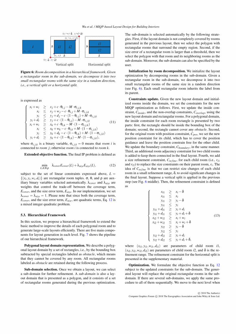
Figure 6: Room decomposition in a hierarchical framework. Givena rectangular room in the sub-domain, we decompose it into twosmall rectangular rooms with the same size in a random direction,i.e., a vertical split or a horizontal split.
is expressed as
xi +wi ≥ x j + c ·θi, j−M ·σi, j,kxi ≤ x j +w j− c ·θi, j +M ·σi, j,kyi ≤ y j +d j− c · (1−θi, j)+M ·σi, j,k
yi +di ≥ y j + c · (1−θi, j)−M ·σi, j,kxi +wi ≥ xk + c ·θi,k−M · (1−σi, j,k)
xi ≤ xk +wk− c ·θi,k +M · (1−σi, j,k)yi ≤ yk +dk− c · (1−θi,k)+M · (1−σi, j,k)
yi +di ≥ yk + c · (1−θi,k)−M · (1−σi, j,k),
(11)
where σi, j,k is a binary variable, σi, j,k = 0 means that room i isconnected to room j; otherwise room i is connected to room k.
Extended objective function. The final IP problem is defined as
minL,σ,θ,ρ
λcoverEcover(L)+λsizeEsize(L), (12)
subject to the set of linear constraints expressed above, L ={(xi,yi,wi,di)} are rectangular room tuples. σ, θ, and ρ are aux-iliary binary variables selected automatically. λcover and λsize areweights that control the trade-off between the coverage term,Ecover, and the size error term, Esize. In our implementation, we setλcover = λsize = 1. Please note that since both the coverage term,Ecover, and the size error term, Esize, are quadratic terms, Eq. 12 isa mixed integer quadratic problem.
5.3. Hierarchical Framework
In this section, we propose a hierarchical framework to extend thebasic method to improve the details of each polygonal room and togenerate large-scale layouts efficiently. There are five main compo-nents for layout generation in each level. Fig. 7 shows the pipelineof our hierarchical framework.
Polygonal layout domain representation. We describe a polyg-onal layout domain by a set of rectangles, i.e., by the bounding boxsubtracted by special rectangles labeled as obstacle, which meansthat they cannot be covered by any room. All rectangular roomslabeled as obstacle are retained during the following process.
Sub-domain selection. Once we obtain a layout, we can selecta sub-domain for further refinement. A sub-domain is also a lay-out domain that is presented as a polygon, and it consists of a setof rectangular rooms generated during the previous optimization.
The sub-domain is selected automatically by the following strate-gies. First, if the layout domain is not completely covered by roomsgenerated in the previous layout, then we select the polygon withrectangular rooms that surround the empty region. Second, if thesize error of a rectangular room is larger than a threshold, then weselect the polygon with that room and its neighboring rooms as thesub-domain. Moreover, the sub-domain can also be specified by theuser.
Initialization by room decomposition. We initialize the layoutoptimization by decomposing rooms in the sub-domain. Given arectangular room in the sub-domain, we decompose it into twosmall rectangular rooms of the same size in a random direction(see Fig. 6). Each small rectangular room inherits the label fromits parent.
Constraints update. Given the new layout domain and initial-ized rooms inside the domain, we set the constraints for the newMIQP optimization as follows. First, we update the inside con-straint, Cinside, and the non-overlap constraints, Coverlap, using thenew layout domain and rectangular rooms. For a polygonal domain,the inside constraint for each room rectangle is presented by twoparts: first, the rectangle should be inside the bounding box of thedomain; second, the rectangle cannot cover any obstacle. Second,for the original room with position constraint, Cpos, we set the newposition constraint for its child, which has to cover the positionguidance and leave the position constrain free for the other child.We update the boundary constraint, Cboundary, in the same manner.Third, an additional room adjacency constraint for two child roomsis added to keep them connected in the final layout. Fourth, we adda size refinement constraint, Cre f ine, for each child room (i.e., ri1and ri2) to replace the size constraints on their parent room, ri. Theidea of Cre f ine is that we can restrict size changes of each childroom in a small refinement range, δ, to avoid significant changes inthe final layout. Suppose a vertical split is applied in the previousstep (see Fig. 6 middle). Then, the refinement constraint is definedas
xi1 ≥ xi−δ
xi1 ≤ xiyi1 ≥ yi−δ
yi1 ≤ yiyi1 +di1 ≥ yi +diyi1 +di1 ≤ yi +di +δ
xi2 +wi2 ≥ xi +wixi2 +wi2 ≤ xi +wi +δ
yi2 ≥ yi−δ
yi2 ≤ yiyi2 +di2 ≥ yi +diyi2 +di2 ≤ yi +di +δ,
(13)
where (xi1,yi1,wi1,di1) are parameters of child room i1,(xi2,yi2,wi2,di2) are parameters of child room i2, and δ is the re-finement range. The refinement constraint for the horizontal split ispresented in the supplementary material.
Optimization. We formulate the objective function as Eq. 12subject to the updated constraints for the sub-domain. The gener-ated layout will replace the original rectangular rooms in the sub-domain. If there are several sub-domains, we apply the same pro-cedure to all of them sequentially. We move to the next level when
c© 2018 The Author(s)Computer Graphics Forum c© 2018 The Eurographics Association and John Wiley & Sons Ltd.
Wu et al. / MIQP-based Layout Design for Building Interiors
Final ResultIntermediate Result Sub-domain SelectionInput Layout DomainInitialization &
Constraints Update Intermediate Result
Kitchen1.75 x 2.50
S.Room1.75 x 2.25
Study2.50 x 2.00Corridor
1.25 x 2.00
Living3.75 x 2.75
Dining2.25 x 2.50
Bedroom3.25 x 2.00
M. Bedroom2.25 x 3.25
M. Bedroom2.25 x 3.25
Bedroom3.25 x 2.00
Corridor1.25 x 2.00
Study2.50 x 2.00
Living3.75 x 2.75
Dining2.25 x 2.50
Kitchen1.75 x 2.50
S.Room1.75 x 2.25
M. Bedroom2.25 x 3.25
Bedroom3.25 x 2.00
Corridor1.25 x 2.00
Study2.50 x 2.00
Living3.75 x 2.75
M. Bedroom2.25 x 3.25
Bedroom3.25 x 2.00
Corridor1.25 x 2.00
Study2.50 x 2.00
Living3.75 x 2.75
M. Bedroom2.25 x 3.25
Bedroom3.25 x 2.00
Corridor1.25 x 2.00
Study2.50 x 2.00
Living3.75 x 2.75
S. Room1.75 x 2.25
S. Room1.75 x 2.25
Dining2.25 x 2.25
Dining2.25 x 2.25
Kitchen2.00 x 2.75
Kitchen2.00 x 2.75
(a) (b) (c) (d) (e) (f)
Obstacle
Obstacle
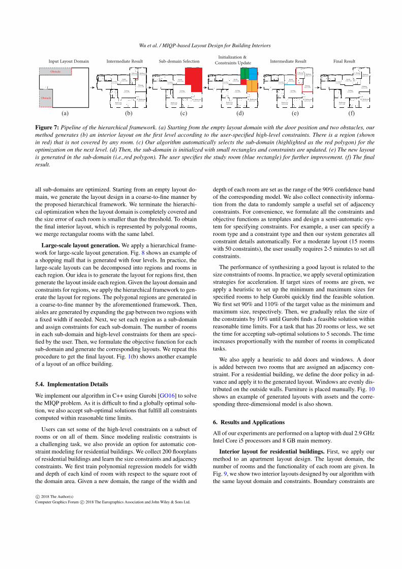
Figure 7: Pipeline of the hierarchical framework. (a) Starting from the empty layout domain with the door position and two obstacles, ourmethod generates (b) an interior layout on the first level according to the user-specified high-level constraints. There is a region (shownin red) that is not covered by any room. (c) Our algorithm automatically selects the sub-domain (highlighted as the red polygon) for theoptimization on the next level. (d) Then, the sub-domain is initialized with small rectangles and constraints are updated. (e) The new layoutis generated in the sub-domain (i.e.,red polygon). The user specifies the study room (blue rectangle) for further improvement. (f) The finalresult.
all sub-domains are optimized. Starting from an empty layout do-main, we generate the layout design in a coarse-to-fine manner bythe proposed hierarchical framework. We terminate the hierarchi-cal optimization when the layout domain is completely covered andthe size error of each room is smaller than the threshold. To obtainthe final interior layout, which is represented by polygonal rooms,we merge rectangular rooms with the same label.
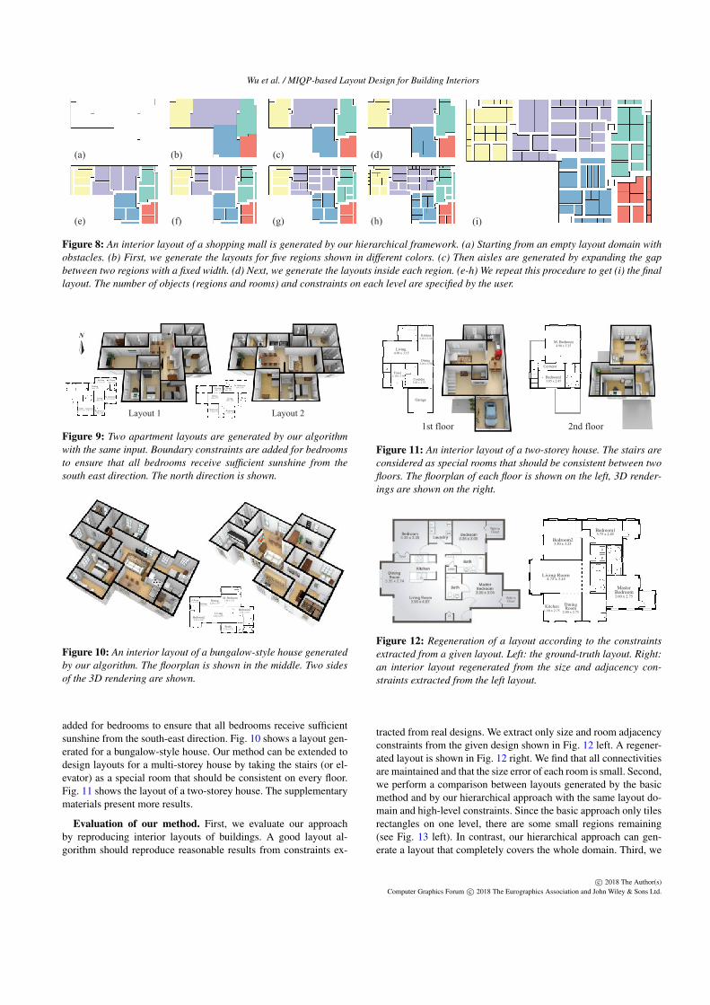
Large-scale layout generation. We apply a hierarchical frame-work for large-scale layout generation. Fig. 8 shows an example ofa shopping mall that is generated with four levels. In practice, thelarge-scale layouts can be decomposed into regions and rooms ineach region. Our idea is to generate the layout for regions first, thengenerate the layout inside each region. Given the layout domain andconstraints for regions, we apply the hierarchical framework to gen-erate the layout for regions. The polygonal regions are generated ina coarse-to-fine manner by the aforementioned framework. Then,aisles are generated by expanding the gap between two regions witha fixed width if needed. Next, we set each region as a sub-domainand assign constraints for each sub-domain. The number of roomsin each sub-domain and high-level constraints for them are speci-fied by the user. Then, we formulate the objective function for eachsub-domain and generate the corresponding layouts. We repeat thisprocedure to get the final layout. Fig. 1(b) shows another exampleof a layout of an office building.
5.4. Implementation Details
We implement our algorithm in C++ using Gurobi [GO16] to solvethe MIQP problem. As it is difficult to find a globally optimal solu-tion, we also accept sub-optimal solutions that fulfill all constraintscomputed within reasonable time limits.
Users can set some of the high-level constraints on a subset ofrooms or on all of them. Since modeling realistic constraints isa challenging task, we also provide an option for automatic con-straint modeling for residential buildings. We collect 200 floorplansof residential buildings and learn the size constraints and adjacencyconstraints. We first train polynomial regression models for widthand depth of each kind of room with respect to the square root ofthe domain area. Given a new domain, the range of the width and
depth of each room are set as the range of the 90% confidence bandof the corresponding model. We also collect connectivity informa-tion from the data to randomly sample a useful set of adjacencyconstraints. For convenience, we formulate all the constraints andobjective functions as templates and design a semi-automatic sys-tem for specifying constraints. For example, a user can specify aroom type and a constraint type and then our system generates allconstraint details automatically. For a moderate layout (15 roomswith 50 constraints), the user usually requires 2-5 minutes to set allconstraints.
The performance of synthesizing a good layout is related to thesize constraints of rooms. In practice, we apply several optimizationstrategies for acceleration. If target sizes of rooms are given, weapply a heuristic to set up the minimum and maximum sizes forspecified rooms to help Gurobi quickly find the feasible solution.We first set 90% and 110% of the target value as the minimum andmaximum size, respectively. Then, we gradually relax the size ofthe constraints by 10% until Gurobi finds a feasible solution withinreasonable time limits. For a task that has 20 rooms or less, we setthe time for accepting sub-optimal solutions to 5 seconds. The timeincreases proportionally with the number of rooms in complicatedtasks.
We also apply a heuristic to add doors and windows. A dooris added between two rooms that are assigned an adjacency con-straint. For a residential building, we define the door policy in ad-vance and apply it to the generated layout. Windows are evenly dis-tributed on the outside walls. Furniture is placed manually. Fig. 10shows an example of generated layouts with assets and the corre-sponding three-dimensional model is also shown.
6. Results and Applications
All of our experiments are performed on a laptop with dual 2.9 GHzIntel Core i5 processors and 8 GB main memory.
Interior layout for residential buildings. First, we apply ourmethod to an apartment layout design. The layout domain, thenumber of rooms and the functionality of each room are given. InFig. 9, we show two interior layouts designed by our algorithm withthe same layout domain and constraints. Boundary constraints are
c© 2018 The Author(s)Computer Graphics Forum c© 2018 The Eurographics Association and John Wiley & Sons Ltd.
Wu et al. / MIQP-based Layout Design for Building Interiors
(a) (b) (c) (d)
(e) (f) (g) (h) (i)
Figure 8: An interior layout of a shopping mall is generated by our hierarchical framework. (a) Starting from an empty layout domain withobstacles. (b) First, we generate the layouts for five regions shown in different colors. (c) Then aisles are generated by expanding the gapbetween two regions with a fixed width. (d) Next, we generate the layouts inside each region. (e-h) We repeat this procedure to get (i) the finallayout. The number of objects (regions and rooms) and constraints on each level are specified by the user.
Layout 1 Layout 2Study
1.75 x 3.25
Kitchen2.75 x 1.50
Living2.50 x 3.75
Dining3.00 x 1.75
S. Room2.25 x 1.50
M. Bedroom2.75 x 3.00
Bedroom12.00 x 3.25 Bedroom2
2.50 x 2.00
S. Room2.00 x 1.75
Kitchen2.50 x 1.75
M. Bedroom3.50 x 3.00
Living4.00 x 3.00
Dining3.00 x 1.75
Bedroom12.50 x 3.25 Bedroom2
2.25 x 2.75
N
Figure 9: Two apartment layouts are generated by our algorithmwith the same input. Boundary constraints are added for bedroomsto ensure that all bedrooms receive sufficient sunshine from thesouth east direction. The north direction is shown.
Study2.75 x 1.75
Bedroom23.25 x 2.50
Bedroom13.25 x 1.75Living
3.50 x 2.75
M. Bedroom3.50 x 2.25Dining
2.25 x 1.75S. Room1.75 x 1.50
Kitchen1.50 x 2.75
Figure 10: An interior layout of a bungalow-style house generatedby our algorithm. The floorplan is shown in the middle. Two sidesof the 3D rendering are shown.
added for bedrooms to ensure that all bedrooms receive sufficientsunshine from the south-east direction. Fig. 10 shows a layout gen-erated for a bungalow-style house. Our method can be extended todesign layouts for a multi-storey house by taking the stairs (or el-evator) as a special room that should be consistent on every floor.Fig. 11 shows the layout of a two-storey house. The supplementarymaterials present more results.
Evaluation of our method. First, we evaluate our approachby reproducing interior layouts of buildings. A good layout al-gorithm should reproduce reasonable results from constraints ex-
1st floor 2nd floor
Bedroom13.85 x 2.45
M. Bedroom4.90 x 5.25
Corridor
Living4.90 x 3.15
Dining2.10 x 3.50
Kitchen2.10 x 3.50
Foyer2.10 x 3.50
Corridor3.85 x 1.75
Garage
Figure 11: An interior layout of a two-storey house. The stairs areconsidered as special rooms that should be consistent between twofloors. The floorplan of each floor is shown on the left, 3D render-ings are shown on the right.
Bedroom23.50 x 3.25
Bedroom13.75 x 2.45
Living Room4.75 x 3.45
Master
3.00 x 2.75Bedroom
Dining
2.00 x 2.75Room1.50 x 2.75
Kitchen
3.35 x 3.35 3.35 x 3.05
3.35 x 2.74
3.35 x 3.05
3.96 x 4.87
Figure 12: Regeneration of a layout according to the constraintsextracted from a given layout. Left: the ground-truth layout. Right:an interior layout regenerated from the size and adjacency con-straints extracted from the left layout.
tracted from real designs. We extract only size and room adjacencyconstraints from the given design shown in Fig. 12 left. A regener-ated layout is shown in Fig. 12 right. We find that all connectivitiesare maintained and that the size error of each room is small. Second,we perform a comparison between layouts generated by the basicmethod and by our hierarchical approach with the same layout do-main and high-level constraints. Since the basic approach only tilesrectangles on one level, there are some small regions remaining(see Fig. 13 left). In contrast, our hierarchical approach can gen-erate a layout that completely covers the whole domain. Third, we
c© 2018 The Author(s)Computer Graphics Forum c© 2018 The Eurographics Association and John Wiley & Sons Ltd.

Wu et al. / MIQP-based Layout Design for Building Interiors
S. Room2.10 x 2.80
Kitchen3.50 x 1.75 M.Bedroom
2.45 x 3.85
Foyer3.50 x 3.50
Dining3.15 x 1.75
Bedroom12.80 x 3.50
Bedroom22.80 x 2.10
Study2.10 x 2.10
Corridor4.90 x 1.05
Living3.15 x 3.50
Living3.50 x 3.50
Kitchen3.50 x 1.75
S. Room2.10 x 3.15
Bedroom12.80 x 3.50
Foyer3.50 x 3.50
Dining3.15 x 1.75
Bedroom22.80 x 2.10
Study2.10 x 2.10
Corridor4.90 x 1.05
M.Bedroom2.45 x 4.20
Figure 13: Given the same input, we perform a comparison be-tween our basic method and our hierarchical approach. Left: thelayout generated by our basic method. Regions that are not coveredare highlighted in red. Right: the layout generated by the hierarchi-cal approach.
Time (sec.)
Fig. 1 (a) 13 13,13,2,1,3,8 40 7.26
Fig. 1 (b) 154 154,154,0,0,0,0 308 85.69
Fig. 2 5 5,5,0,0,1,4 15 0.13
Fig. 4 (a) 5 5,5,0,1,3,4 18 0.16
Fig. 4 (b) 15 15,15,2,1,7,14 54 11.31
Fig. 7 14 14,14,1,1,6,13 49 18.17
Fig. 8 140 140,140,0,6,0,0 286 78.63
Fig. 9 left 15 15,15,2,1,7,14 54 16.17
Fig. 9 right 15 15,15,2,1,7,14 54 11.09
Fig. 10 15 15,15,2,1,7,14 54 17.95
Fig. 11 13 13,13,2,1,2,6 37 1.52
Fig. 12 13 13,13,2,1,5,11 45 10.44
Fig. 13 left 15 15,15,2,1,7,14 54 10.69
Fig. 13 right 15 15,15,2,1,7,14 54 10.72
Fig. 15 left 119 119,119,0,6,0,0 244 67.14
Fig. 15 right 95 95,95,0,0,0,0 190 53.57
Fig. 16 left 111 111,111,0,1,0,0 223 61.75
Fig. 16 right 154 154,154,0,0,0,0 208 86.88
Figure #Room #Constraints Total
Table 1: For each example shown in the paper, we present the num-ber of rooms, the number of each kind of constraint, the number oftotal constraints, and running time. In the third column, the num-bers of Csize, Coverlap, Cratio, Cpos, Cboundary, and Cad j constraintsare given.
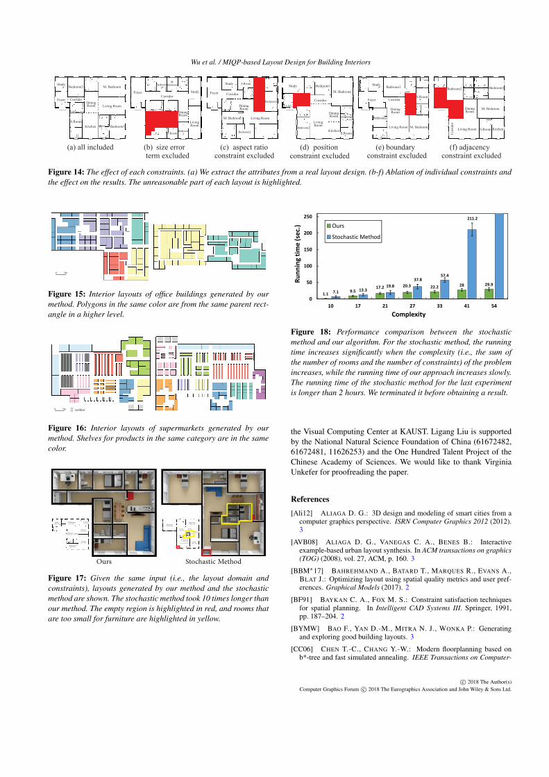
evaluate the effect of each constraint by performing leave-one-outtests. Fig. 14 shows the effect of each constraint. We can see thatthe kitchen size is unreasonable if the size error term is excluded.Without the aspect ratio constraint, the kitchen is too narrow. Thefoyer is not connected to the main door without the position con-straint. When the boundary constraint for the kitchen is excluded,the kitchen is not adjacent to the boundary of the house, which isnot good for emission of kitchen exhaust. When the room adja-cency constraints are excluded, there is no pathway to other roomsexcept the study. The performance of our algorithm is shown in Ta-ble 1. In our experiments, our algorithm can generate a mid-sizelayout in 15 seconds on average.
We also evaluate our method on large-scale examples, e.g.,
rooms in an office building, booths in a shopping mall, and shelvesin a supermarket. Fig. 15 shows two layouts of office buildings gen-erated by our algorithm. In Fig. 16, two layouts of supermarkets areshown.
Comparison with other methods. For comparison, we imple-mented a stochastic optimization algorithm, i.e., the non-parallelversion of [MSK10]. In the initialization step, we add rectangularrooms with the same size to the layout domain. The approach it-eratively performs one of the following operations randomly: (1)swapping rooms or (2) sliding a wall. We evaluate the proposedlayout by the objective value E. If E is smaller than the objectivevalue of previous layout E, we always accept the layout; otherwise,we accept it with the probability of exp(−E′−E)/t, where t is thetemperature. We gradually reduce the temperature t in each itera-tion. The algorithm terminates when E is smaller than a threshold.Fig. 18 shows the performance of the two methods on differentcomplexities of the problem, where the complexity of the problemis defined as the sum of the number of rooms and the number ofspecified constraints. As the complexity of the input increases, therunning time of the stochastic method increases significantly, whilethe running time of our method increases slowly. When the sum ofthe number of rooms and the number of constraints is larger than50, the stochastic method takes more than two hours. To illustratethe problem, Fig. 17 left shows a layout generated by our algo-rithm, while Fig. 17 right shows a layout generated by the stochas-tic method that took 10 times longer to generate than our methodtook. At this point in time, the stochastic method has still not founda feasible solution that fulfills all constraints. We find that there isan uncovered region and several rooms are too small for furniture.
Limitations. The main limitation of our method is that we can-not currently handle non axis-aligned polygons. One possible ap-proach to overcome this limitation is to apply shape deformationsto generate rooms in arbitrary shapes.
7. Conclusions
In this paper, we propose a novel method for interior layout design.We formulate the problem using mixed integer quadratic program-ming. We propose a parametric layout representation suitable forthis optimization framework and derive how to model five impor-tant high-level constraints for layout modeling as linear constraints.We propose a hierarchical framework to generate complicated lay-outs in a coarse-to-fine manner. We demonstrate that our methodis faster by multiple orders of magnitude than previous work us-ing stochastic optimization. Our work can generate a wide varietyof layouts, such as residential buildings, exhibitions, supermarkets,department stores, etc. In future work, we would like to extend ourmethod to other layout design problems, e.g., warehouses, gamelayouts, and electrical layouts. We also would like to extend ourhierarchical framework to large-scale urban planning. It would alsobe interesting to integrate the idea of network design to generatelayouts that satisfy both shape and network constraints.
Acknowledgment
This work was supported by the KAUST Office of Sponsored Re-search (OSR) under Award No. OCRF-2014-CGR3-62140401, and
c© 2018 The Author(s)Computer Graphics Forum c© 2018 The Eurographics Association and John Wiley & Sons Ltd.
Wu et al. / MIQP-based Layout Design for Building Interiors
(a) all included size error aspect ratio position (e) boundary (f) adjacency term excluded
(b) (c)constraint excluded
(d)constraint excluded constraint excluded constraint excluded
Bedroom2Study
M. Bedroom
Living Room
Foyer Corridor
S.RoomKitchen
Dining Room
Bedroom1
Foyer Study
LivingRoom
Dining Room
Bedroom2
Bedroom1
BedroomM.
Corridor
Kitchen
S.Room
Foyer Corridor
Study Bedroom2S.Room
Kitchen
Dining Room
M. Bedroom Living Room
Bedroom1
Study
Foyer
Bedroom1M. Bedroom
Corridor
Bedroom2
LivingRoom
Dining Room
KitchenS.Room
Foyer Foyer
Study
Study
Corridor
Living Room
Bedroom1
Bedroom2
Dining Room
Kitchen
S.Room
M. Bedroom
Bedroom1
M. BedroomDining Room
KitchenS.RoomLiving Room
Bedroom2
Cor
ridor
Foyer
Study
Bedroom2
S.Room
Kitchen
Dining Room
Living RoomM. Bedroom
Corridor
Bedroom1
Figure 14: The effect of each constraints. (a) We extract the attributes from a real layout design. (b-f) Ablation of individual constraints andthe effect on the results. The unreasonable part of each layout is highlighted.
0 5m
Figure 15: Interior layouts of office buildings generated by ourmethod. Polygons in the same color are from the same parent rect-angle in a higher level.
0 5m cashier
Figure 16: Interior layouts of supermarkets generated by ourmethod. Shelves for products in the same category are in the samecolor.
Ours Stochastic Method
Study3.40 x 4.50
M. Bedroom3.75 x 2.25
Bedroom15.25 x 4.50
Bedroom24.90 x 3.00
Living3.40 x 4.15
Kitchen1.90 x 3.75
Dining3.00 x 1.50
S. Room1.50 x 2.25
Study3.40 x 2.65
M. Bedroom4.15 x 2.65
Bedroom24.50 x 2.25
Living3.75 x 5.65
Kitchen3.75 x 3.00
Dining1.90 x 3.40
S. Room2.25 x 2.65
Bedroom12.65 x 5.65
Figure 17: Given the same input (i.e., the layout domain andconstraints), layouts generated by our method and the stochasticmethod are shown. The stochastic method took 10 times longer thanour method. The empty region is highlighted in red, and rooms thatare too small for furniture are highlighted in yellow.
1.19.5
17.2 20.3 22.2 28 29.9
7.1 13.319.8
37.857.4
211.2
0
50
100
150
200
250
10 17 21 27 33 41 54
Running time (sec.)
Complexity
Ours
Stochastic Method
Figure 18: Performance comparison between the stochasticmethod and our algorithm. For the stochastic method, the runningtime increases significantly when the complexity (i.e., the sum ofthe number of rooms and the number of constraints) of the problemincreases, while the running time of our approach increases slowly.The running time of the stochastic method for the last experimentis longer than 2 hours. We terminated it before obtaining a result.
the Visual Computing Center at KAUST. Ligang Liu is supportedby the National Natural Science Foundation of China (61672482,61672481, 11626253) and the One Hundred Talent Project of theChinese Academy of Sciences. We would like to thank VirginiaUnkefer for proofreading the paper.
References
[Ali12] ALIAGA D. G.: 3D design and modeling of smart cities from acomputer graphics perspective. ISRN Computer Graphics 2012 (2012).3
[AVB08] ALIAGA D. G., VANEGAS C. A., BENES B.: Interactiveexample-based urban layout synthesis. In ACM transactions on graphics(TOG) (2008), vol. 27, ACM, p. 160. 3
[BBM∗17] BAHREHMAND A., BATARD T., MARQUES R., EVANS A.,BLAT J.: Optimizing layout using spatial quality metrics and user pref-erences. Graphical Models (2017). 2
[BF91] BAYKAN C. A., FOX M. S.: Constraint satisfaction techniquesfor spatial planning. In Intelligent CAD Systems III. Springer, 1991,pp. 187–204. 2
[BYMW] BAO F., YAN D.-M., MITRA N. J., WONKA P.: Generatingand exploring good building layouts. 3
[CC06] CHEN T.-C., CHANG Y.-W.: Modern floorplanning based onb*-tree and fast simulated annealing. IEEE Transactions on Computer-
c© 2018 The Author(s)Computer Graphics Forum c© 2018 The Eurographics Association and John Wiley & Sons Ltd.
Wu et al. / MIQP-based Layout Design for Building Interiors
Aided Design of Integrated Circuits and Systems 25, 4 (2006), 637–650.2
[CEW∗08] CHEN G., ESCH G., WONKA P., MÜLLER P., ZHANG E.:Interactive procedural street modeling. In ACM transactions on graphics(TOG) (2008), vol. 27, ACM, p. 103. 3
[CGC10] CHEN G., GUO W., CHEN Y.: A pso-based intelligent decisionalgorithm for vlsi floorplanning. Soft Computing 14, 12 (2010), 1329–1337. 2
[CZ10] CHEN J., ZHU W.: A hybrid genetic algorithm for vlsi floor-planning. In Intelligent Computing and Intelligent Systems (ICIS), 2010IEEE International Conference on (2010), vol. 2, IEEE, pp. 128–132. 2
[DB08] DONATH D., BÖHME L. F. G.: Constraint-based design in par-ticipatory housing planning. International Journal of architectural com-puting 6, 1 (2008), 97–117. 2
[Dou07] DOULGERAKIS A.: Genetic and embryology in layout planning.Master of Science in Adaptive Architecture and Computation, Universityof London (2007). 2
[DRCMPI07] DEL RÍO-CIDONCHA G., MARTÍNEZ-PALACIOS J.,IGLESIAS J. E.: A multidisciplinary model for floorplan design. In-ternational journal of production research 45, 15 (2007), 3457–3476.2
[Dua05] DUARTE J. P.: A discursive grammar for customizing masshousing: the case of siza’s houses at malagueira. Automation in con-struction 14, 2 (2005), 265–275. 2
[DZH∗02] DONG S., ZHOU S., HONG X., CHENG C., GU J., CAI Y.:An optimum placement search algorithm based on extended corner blocklist. Journal of Computer Science and Technology 17, 6 (2002), 699–707.2
[EF99] ELEZKURTAJ T., FRANCK G.: Genetic algorithms in supportof creative architectural design. EUROPEAN COMPUTER AIDED AR-CHITECTURAL DESIGN AND EDUCATION 17 (1999), 645–651. 2
[FUC∗88] FLEMMING, ULRICH, COYNE, GLAVIN R. F., TIMOTHY J.:A generative expert system for the design of building layouts – version2. Cad and Robotics in Architecture and Construction (1988), 75–81. 2
[FYY∗16] FENG T., YU L.-F., YEUNG S.-K., YIN K., ZHOU K.:Crowd-driven mid-scale layout design. ACM Trans. Graph. 35, 4 (2016),132–1. 3
[GO16] GUROBI OPTIMIZATION I.: Gurobi optimizer reference manual,2016. URL: http://www.gurobi.com. 7
[Hsu00] HSU Y.-C.: Constraint based space planning: A case study.ACADIA Quarterly 19, 3 (2000), 2–3. 2
[Hua16] HUA H.: Irregular architectural layout synthesis with graphicalinputs. Automation in Construction 72 (2016), 388–396. 3
[HWB95] HARADA M., WITKIN A., BARAFF D.: Interactivephysically-based manipulation of discrete/continuous models. In Pro-ceedings of the 22nd annual conference on Computer graphics and in-teractive techniques (1995), ACM, pp. 199–208. 2
[KF00] KIYOTA K., FUJIYOSHI K.: Simulated annealing search throughgeneral structure floorplans using sequence-pair. In Circuits and Sys-tems, 2000. Proceedings. ISCAS 2000 Geneva. The 2000 IEEE Interna-tional Symposium on (2000), vol. 3, IEEE, pp. 77–80. 2
[KS05] KEATRUANGKAMALA K., SINAPIROMSARAM K.: Opti-mizing architectural layout via mixed integer programming. In CAADFUTURES (2005), vol. 11, pp. 175–184. 2
[LC04] LIN J.-M., CHANG Y.-W.: Tcg-s: orthogonal coupling ofp/sup*/-admissible representations for general floorplans. IEEE Trans-actions on Computer-Aided Design of Integrated Circuits and Systems23, 6 (2004), 968–980. 2
[LFT00] LI S.-P., FRAZER J., TANG M.-X.: A constraint based genera-tive system for floor layouts. 2
[LHP11] LEBLANC L., HOULE J., POULIN P.: Component-based mod-eling of complete buildings. In Proceedings of Graphics Interface 2011
(2011), Canadian Human-Computer Communications Society, pp. 87–94. 2
[LWKF17] LIU C., WU J., KOHLI P., FURUKAWA Y.: Raster-to-vector:Revisiting floorplan transformation. In International Conference onComputer Vision (ICCV) (2017). 3
[LYAM13] LIU H., YANG Y.-L., ALHALAWANI S., MITRA N. J.:Constraint-aware interior layout exploration for pre-cast concrete-basedbuildings. The Visual Computer 29, 6-8 (2013), 663–673. 3
[MAR07] MONI D. J., ARUMUGAM S., RANI G. N.: Vlsi floorplanningrelying on differential evolution algorithm. ICGST International Journalon Artificial Intelligence and Machine Learning 7, 1 (2007), 62–67. 2
[MSK10] MERRELL P., SCHKUFZA E., KOLTUN V.: Computer-generated residential building layouts. In ACM Transactions on Graphics(TOG) (2010), vol. 29, ACM, p. 181. 1, 3, 9
[MVLS14] MA C., VINING N., LEFEBVRE S., SHEFFER A.: Gamelevel layout from design specification. In Computer Graphics Forum(2014), vol. 33, Wiley Online Library, pp. 95–104. 3
[MXM09] MAO F., XU N., MA Y.: Hybrid algorithm for floorplanningusing b*-tree representation. In Intelligent Information Technology Ap-plication, 2009. IITA 2009. Third International Symposium on (2009),vol. 3, IEEE, pp. 228–231. 2
[NFMK97] NAKATAKE S., FUJIYOSHI K., MURATA H., KAJITANI Y.:Module placement on bsg-structure and ic layout applications. In Pro-ceedings of the 1996 IEEE/ACM international conference on Computer-aided design (1997), IEEE Computer Society, pp. 484–491. 2
[Nil06] NILKAEW P.: Assistant tool for architectural layout design bygenetic algorithm. 2
[NNA06] NINOMIYA H., NUMAYAMA K., ASAI H.: Two-staged tabusearch for floorplan problem using o-tree representation. In Evolution-ary Computation, 2006. CEC 2006. IEEE Congress on (2006), IEEE,pp. 718–724. 2
[PYB∗16] PENG C.-H., YANG Y.-L., BAO F., FINK D., YAN D.-M.,WONKA P., MITRA N. J.: Computational network design from func-tional specifications. ACM Transactions on Graphics (TOG) 35, 4(2016), 131. 3
[PYW14] PENG C.-H., YANG Y.-L., WONKA P.: Computing layoutswith deformable templates. ACM Transactions on Graphics (TOG) 33,4 (2014), 99. 2, 3
[RCMLS96] RAU-CHAPLIN A., MACKAY-LYONS B., SPIERENBURGP.: The lahave house project: Towards an automated architectural designservice. Cadex 96 (1996), 24–31. 2
[RSM17] ROSSER J. F., SMITH G., MORLEY J. G.: Data-driven esti-mation of building interior plans. International Journal of GeographicalInformation Science 31, 8 (2017), 1652–1674. 3
[SDD12] SINGHA T., DUTTA H., DE M.: Optimization of floor-planningusing genetic algorithm. Procedia Technology 4 (2012), 825–829. 2
[Sec12] SECHEN C.: VLSI placement and global routing using simulatedannealing, vol. 54. Springer Science & Business Media, 2012. 2
[STBB14] SMELIK R. M., TUTENEL T., BIDARRA R., BENES B.: Asurvey on procedural modelling for virtual worlds. In Computer Graph-ics Forum (2014), vol. 33, Wiley Online Library, pp. 31–50. 3
[SVW∗11] SENGUPTA D., VENERIS A., WILTON S., IVANOV A.,SALEH R.: Sequence pair based voltage island floorplanning. InGreen Computing Conference and Workshops (IGCC), 2011 Interna-tional (2011), IEEE, pp. 1–6. 2
[YWVW13] YANG Y.-L., WANG J., VOUGA E., WONKA P.: Urban pat-tern: Layout design by hierarchical domain splitting. ACM Transactionson Graphics (TOG) 32, 6 (2013), 181. 3
c© 2018 The Author(s)Computer Graphics Forum c© 2018 The Eurographics Association and John Wiley & Sons Ltd.