mint 709 capstone project report
TRANSCRIPT
MINT 709 Capstone Project Report Anycast network solutions for DataGardens’ Syntropy implementation and their performance investigations
Kevin Han 11/23/2009

Master of Science in Internetworking, University of Alberta
Capstone project report
Kevin Han Page 2
Abstract
Syntropy is a flagship product from a local IT company DataGardens. Syntropy is
a software system mainly deployed as a virtual machine within a 3rd party hypervisor. A
network of syntropy nodes is called “Wide Area Virtualized Enterprise” or WAVE by
DataGardens. It achieves virtual server migration with low latency through its Syntropy.
This project is to implement two anycast network solutions using OSPF and IS-IS
to achieve the shortest latency of services after the virtual servers are migrated to a
different physical locations. This project also compares the two solutions and identifies
the advantages and disadvantages.
Acknowledgement
Many thanks go to Dr. Mike MacGregor getting me involved in this project.
Thanks for Mr. Ashishkumar Patel’s network design. I also thank Carmen Sarnecki, a
very good friend of mine for helping me with the language to put the report together.

Master of Science in Internetworking, University of Alberta
Capstone project report
Kevin Han Page 3
Table of Contents Chapter 1 Introduction ..................................................................................................................... 5
1.1 Subject ............................................................................................................................. 5
1.2 Syntropy vs. VMotion ..................................................................................................... 5
1.3 Existing solution .............................................................................................................. 6
1.4 Proposed anycast solutions .............................................................................................. 7
Chapter 2 Anycast ........................................................................................................................... 9
Chapter 3 OSPF ............................................................................................................................. 13
Chapter 4 IS-IS .............................................................................................................................. 16
Chapter 5 Project Design ............................................................................................................... 18
Chapter 6 Project implementation ................................................................................................. 20
6.1 OSPF implementation ......................................................................................................... 20
6.1.1 R1 configuration ........................................................................................................... 20
6.1.2 R2 configuration ........................................................................................................... 24
6.1.3 R3 configuration ........................................................................................................... 28
6.1.4 R4 Configuration .......................................................................................................... 32
6.2 The following configurations are implemented with IS-IS. ................................................ 36
6.2.1 R1 configuration: .......................................................................................................... 36
6.2.2 R2 configuration: .......................................................................................................... 39
6.2.3 R3 Configuration: ......................................................................................................... 42
6.2.4 R4 Configuration: ......................................................................................................... 45
Chapter 7 Test results .................................................................................................................... 50
7.1 OSPF test results ................................................................................................................. 50

Master of Science in Internetworking, University of Alberta
Capstone project report
Kevin Han Page 4
7.2 IS-IS test results. .................................................................................................................. 59
7.3 Routes change during the test. ............................................................................................. 65
Chapter 8 Things to consider and conclusion ................................................................................ 70
Reference ....................................................................................................................................... 72

Master of Science in Internetworking, University of Alberta
Capstone project report
Kevin Han Page 5
Chapter 1 Introduction
1.1 Subject This project is to search for a solution different from dynamic DNS for a local IT
company, DataGardens. DataGardens flagship product Syntropy utilizes 3rd party
hypervisor to accomplish server migration. It provides an attractive backup and
disaster recovery solution for companies with multiple data centers with average to
slower WAN connections among the data centers. Syntropy is primarily implemented
with VMware ESX [1] servers. During a scheduled maintenance or outage,
administrators can warm fail over the servers from one data center to another center
with a very short interruption to existing services. During an unscheduled outage or
disastrous situation, the administrators can bring up the backup servers from another
data center with very little data lose and continue the services to users.
1.2 Syntropy vs. VMotion Syntropy works similar to VMware VMotion. VMotion works on high bandwidth
low latency networks. VMotion allows you to:
• Perform live migrations with zero downtime, undetectable to the user.
• Continuously and automatically optimize virtual machines within resource pools.
• Perform hardware maintenance without scheduling downtime and without
disrupting business operations.
Master of Science in Internetworking, University of Alberta
Capstone project report
Kevin Han Page 6
• Proactively move virtual machines away from failing or underperforming
servers.[3]
Syntropy works on lower bandwidth, higher latency networks. Syntropy allows
you to:
• Perform migrations with some downtime, detectable to the user. Should not be
done during production.
• With scheduled downtime, hardware maintenance can be arranged quickly and
then carried out.
• Administrator can proactively move virtual machines away from failing data
center to a backup location and vice versa.
• Syntropy can be implemented without VMware; it can be implemented with other
hypervisor products as well.
1.3 Existing solution Mr. Ashishkumar Patel has proposed a dynamic DNS solution by implementing
BIND server. The latency with default configuration is about three minutes and 47
second. A factor that needs to be considered in this solution is the client DNS flush
interval. The Windows XP default DNS flush interval is five minutes. That means, for
a Windows XP client to successfully reconnect to the service, it could possibly take
up to five minutes.
Master of Science in Internetworking, University of Alberta
Capstone project report
Kevin Han Page 7
1.4 Proposed anycast solutions Anycast is a network addressing and routing scheme whereby the data is routed to
the “nearest” or “best” destination as viewed by the routing topology [4]. Anycast,
where client packets are directed towards the server in the anycast group closest to the
client, is widely deployed in DNS today [5]. The reason behind this is to reduce
latency, and increase reliability. In an anycast in DNS solution, there is a group of
DNS servers with the same IP address. The client has no control where its query is
directed to, in fact, the clients’ queries are directed to the nearest and best DNS
servers determined by the routing devices.
My solution uses this anycast theory, but I do not implement a group of servers to
provide the same services. I implemented two servers with the same IP at two
different locations, but only one server is active at any given time. To simulate
Syntropy server migration, I provided one physical server at any given time, but both
servers have the same IP address. How does the client find the active server providing
the services? It is up the network to decide. I have implemented a four-router ring-
shaped network. This network design was used by Mr. Patel in his project; Dr.
MacGregor recommended I use the same network design, so we can provide a
comparison between the two solutions.
I used ping command on the router to simulate the clients acquiring the services to
achieve a more accurate time-out measurement. Because I do not have a copy of

Master of Science in Internetworking, University of Alberta
Capstone project report
Kevin Han Page 8
Syntropy, I used an Ubuntu workstation in the lab and manually switched the network
cable between the two routers to simulate the server migration.
I created two scenarios and compared the downtimes generated in each scenario. I
implemented OSPF in the first scenario, and implemented IS-IS in the second
scenario with the same hardware configuration. All protocols are implemented with
default time intervals. The routers I used are in rack four.

Master of Science in Internetworking, University of Alberta
Capstone project report
Kevin Han Page 9
Chapter 2 Anycast Anycast is a network addressing and routing scheme whereby the data is routed to
the “nearest” or “best” destination as viewed by the routing topology [4].
Figure 2.1 Anycast [6]
Figure 2.1 and Figure 2.2 shows how anycast work. At any given time, there are a
group of nodes with the same IP address, when the red node wants to send date to that IP;
the network will direct that stream of data to the nearest or best green node computed by
the network. This could be determined by hop count, network connection weight or
network policy. The red node in this network does not know which physical green node it
is talking to, and it does not care which green node it is talking to. When one of the green

Master of Science in Internetworking, University of Alberta
Capstone project report
Kevin Han Page 10
nodes is not available, the network will redirect the data traffic from the red node to the
next best green node.
Figure 2.2 Anycast [7]
In computer networking, broadcast is simultaneously sending data to all possible
nodes in the network. Usually it requires all nodes in the same broadcast domain, and
listening to the same broadcast address. Figure 2.3 demonstrates this scenario. All green
nodes and the red node are in the same broadcast domain, and the data traffic is sent out
from the red node to all the green nodes at the same time. All the green nodes must be
listening to a broadcast address. Typical example is Windows file and print sharing.
Figure 2.3 Broadcast [7]
Master of Science in Internetworking, University of Alberta
Capstone project report
Kevin Han Page 11
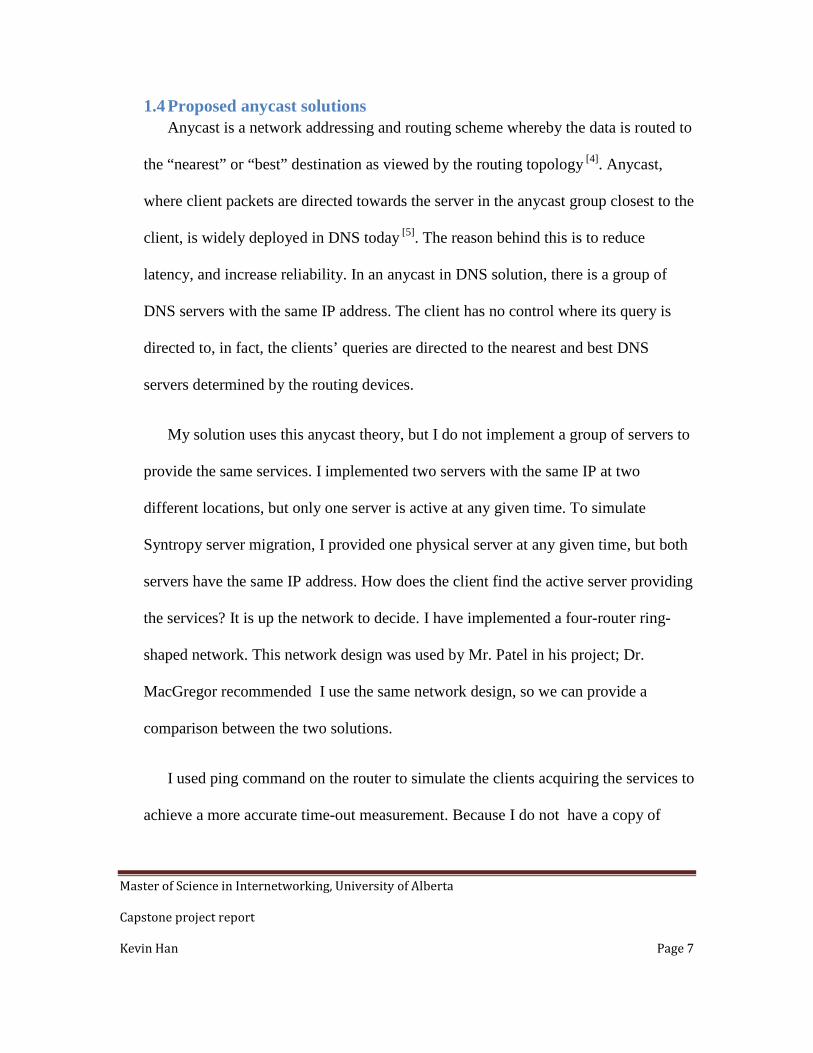
Multicast is a form of one-to-many distribution. A sending node delivers data to a
group of recipients simultaneously. In multicast, distribution tree is the key concept. A
multicast distribution tree can grow with the recipients joining the group; a tree can also
be pruned when the recipients leave the group. The most widely used multicast protocol
is PIM (Protocol Independent Multicast), there are a few variations of implementation,
such as Dense Mode, Sparse Mode, etc. A few examples of the multicast are Internet TV,
streaming media.
Figure 2.4 Multicast [7]
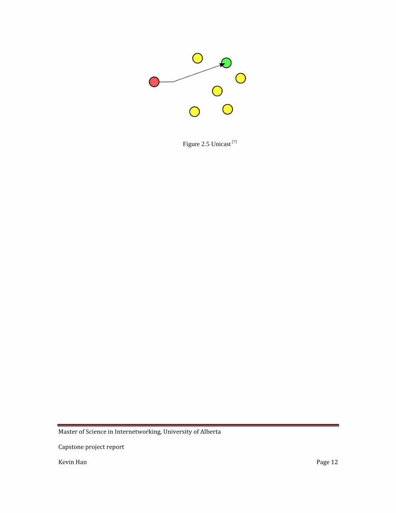
Unicast is one-to-one distribution. One source sends information to one
destination. Unicast messaging is used when a private or unique resource is requested in a
network. Figure 2.5 shows a data stream is sent from the red node to the green node. This
does not mean the red node cannot send a different data stream to one of the yellow
nodes at the same time. Each connection consumes some computing resources on the red
node, and it requires separate network bandwidth to transmit.
Master of Science in Internetworking, University of Alberta
Capstone project report
Kevin Han Page 12
Figure 2.5 Unicast [7]
Master of Science in Internetworking, University of Alberta
Capstone project report
Kevin Han Page 13
Chapter 3 OSPF (The following a few paragraph are quoted from RFC2328)
OSPF is classified as an Interior Gateway Protocol (IGP). This means that it
distributes routing information between routers belonging to a single Autonomous
System. The OSPF protocol is based on link-state or SPF technology. [8]
The OSPF protocol was developed by the OSPF working group of the Internet
Engineering Task Force. It has been designed expressly for the TCP/IP internet
environment, including explicit support for CIDR and the tagging of externally-derived
routing information. [8]
OSPF is a dynamic routing protocol. It quickly detects topological changes in the AS
(such as router interface failures) and calculates new loop-free routes after a period of
convergence. This period of convergence is short and involves a minimum of routing
traffic. [8]
In a link-state routing protocol, each router maintains a database describing the
Autonomous System's topology. This database is referred to as the link-state database.
Each participating router has an identical database. Each individual piece of this database
is a particular router's local state (e.g., the router's usable interfaces and reachable
neighbors). The router distributes its local state throughout the Autonomous System by
flooding. [8]

Master of Science in Internetworking, University of Alberta
Capstone project report
Kevin Han Page 14
All routers run the exact same algorithm, in parallel. From the link-state database,
each router constructs a tree of shortest paths with itself as root. This shortest-path tree
gives the route to each destination in the Autonomous System. [8]
OSPF allows sets of networks to be grouped together. Such a grouping is called an
area. The topology of an area is hidden from the rest of the Autonomous System. This
information hiding enables a significant reduction in routing traffic. [8]
Point-to-point networks
A network that joins a single pair of routers
A 56Kb serial line is an example of a point-to-point network. [8]
Broadcast networks
Networks supporting many (more than two) attached routers, together with the
capability to address a single physical message to all of the attached routers (broadcast).
Neighboring routers are discovered dynamically on these nets using OSPF's Hello
Protocol. The Hello Protocol itself takes advantage of the broadcast capability. The
OSPF protocol makes further use of multicast capabilities, if they exist. Each pair of
routers on a broadcast network is assumed to be able to communicate directly. An
Ethernet is an example of a broadcast network. [8]

Master of Science in Internetworking, University of Alberta
Capstone project report
Kevin Han Page 15
Hello Protocol
The part of the OSPF protocol used to establish and maintain neighbor
relationships. On broadcast networks the Hello Protocol can also dynamically discover
neighboring routers. [8]
HelloInterval
It is the length of time, in seconds, between the Hello Packets that the router sends
on the interface. This value is advertised in the router's Hello Packets. It must be the
same for all routers attached to a common network. The smaller the HelloInterval, the
faster topological changes will be detected; however, more OSPF routing protocol traffic
will ensue. Sample value for a X.25 PDN network: 30seconds. Sample value for a local
area network: 10 seconds. [8]
Master of Science in Internetworking, University of Alberta
Capstone project report
Kevin Han Page 16
Chapter 4 IS-IS IS stands for 'Intermediate systems' in IS-IS protocol, hosts are referred to as 'end
systems'.
OSI IS-IS routing makes use of two-level hierarchical routing. A routing domain
is partitioned into areas. Level-1 routers know the topology in their area, including all
routers and end systems in their area. However, level-1 routers do not know the identity
of routers or destinations outside of their area. Level-1 routers forward all traffic for
destinations outside of their area to a level-2 router in their area. Similarly, level-2 routers
know the level-2 topology, and know which addresses are reachable via each level-2
router. However, level 2 routers do not need to know the topology within any level-1
area, except to the extent that a level-2 router may also be a level-1 router within a single
area. Only level-2 routers can exchange data packets or routing information directly with
external routers located outside of the routing domains. [11]
Hello interval specifies the length of time between the sending of IS-IS hello
PDUs. [9]
The default value is 10. The hello interval multiplied by the hello multiplier
equals the hold time. If the minimal keyword is specified, the hold time is 1 second and
the system computes the hello interval based on the hello multiplier. [9]
Master of Science in Internetworking, University of Alberta
Capstone project report
Kevin Han Page 17
The hello interval can be configured independently for Level-1 and Level-2,
except on serial point-to-point interfaces. (Because only a single type of hello PDU is
sent on serial links, it is independent of Level-1 or Level-2.) [9]
Note A faster hello interval gives faster convergence, but increases bandwidth and CPU
usage. It might also add to instability in the network, due to false failure detection events.
A slower hello interval saves bandwidth and CPU, especially when used in combination
with a higher hello multiplier. This configuration may increase overall network stability,
but typically has slower network convergence as a consequence. [9]
Multiplier specifies the number of IS-IS hello PDUs a neighbor must miss before
the router should declare the adjacency as down. The default value is 3. A multiplier
value of 1 is very aggressive—I recommend a value of at least 2. [9]
Both OSPF and IS-IS are link state protocols. Both use Dijkstra Algorithm to
compute the best route within the network. They both support VLSM and use multicast
hello packets to discover neighboring routers.
Both protocols use 10 second hello interval by default and slightly different dead
intervals. I expect very similar convergence time between the two protocols in a network.

Master of Science in Internetworking, University of Alberta
Capstone project report
Kevin Han Page 18
Chapter 5 Project Design I used four routers and one workstation to simulate Syntropy migration.
Figure 5.1

Master of Science in Internetworking, University of Alberta
Capstone project report
Kevin Han Page 19
Equipment list
Device Name Physical Device
R1 Cisco 2600 (Top)
R2 Cisco 2600 (middle)
R3 Cisco 2600 (bottom)
R4 Cisco 2800
Workstation Workstation 4
Table 5.1

Master of Science in Internetworking, University of Alberta
Capstone project report
Kevin Han Page 20
Chapter 6 Project implementation This chapter explained the routers configurations in the two scenarios. The first part is
showing the OSPF configuration, the second part is showing IS-IS configuration.
6.1 OSPF implementation
6.1.1 R1 configuration “show running-config” command shows the configuration of all four routers.
“show cdp neighbor” command shows the routers connections
R1#sh cdp nei
Capability Codes: R – Router, T – Trans Bridge, B – Source Route Bridge
S – Switch, H – Host, I – IGMP, r – Repeater
Device ID Local Intrfce Holdtme Capability Platform
Port ID
R2 Ser 0/0 178 R 2620 Ser
0/1
R4 Ser 0/1 174 R S I 2821 Ser
0/0/0
This is R1 configuration with OSPF implementation. R1 is the top 2600.
R1>en

Master of Science in Internetworking, University of Alberta
Capstone project report
Kevin Han Page 21
R1#sh run
Building configuration...
Current configuration : 851 bytes
!
version 12.3
service timestamps debug datetime msec
service timestamps log datetime msec
no service password-encryption
!
hostname R1
!
boot-start-marker
boot-end-marker
!
no aaa new-model
ip subnet-zero
!
no ip domain lookup

Master of Science in Internetworking, University of Alberta
Capstone project report
Kevin Han Page 22
!
ip cef
!
interface FastEthernet0/0
description connecting to the testing host moving between two
locations
ip address 192.168.1.1 255.255.255.0
duplex auto
speed auto
no shut
!
interface Serial0/0
description connecting to router R2 on interface s0/1
ip address 192.168.5.1 255.255.255.0
!
interface FastEthernet0/1
no ip address
duplex auto

Master of Science in Internetworking, University of Alberta
Capstone project report
Kevin Han Page 23
speed auto
no shut
!
interface Serial0/1
description connecting to router R4 on interface s0/0/0
ip address 192.168.6.1 255.255.255.0
clock rate 56000
no shut
!
router ospf 100
log-adjacency-changes
network 192.168.1.0 0.0.0.255 area 0
network 192.168.5.0 0.0.0.255 area 0
network 192.168.6.0 0.0.0.255 area 0
!
ip http server
ip classless
!

Master of Science in Internetworking, University of Alberta
Capstone project report
Kevin Han Page 24
voice-port 1/0/0
!
voice-port 1/0/1
!
line con 0
line aux 0
line vty 0 4
!
end
6.1.2 R2 configuration This is show “cdp neighbor” output on R2.
R2#sh cdp nei
Capability Codes: R – Router, T – Trans Bridge, B – Source Route Bridge
S – Switch, H – Host, I – IGMP, r – Repeater
Device ID Local Intrfce Holdtme Capability Platform
Port ID
R3 Ser 0/0 158 R 2620 Ser
0/1
Master of Science in Internetworking, University of Alberta
Capstone project report
Kevin Han Page 25
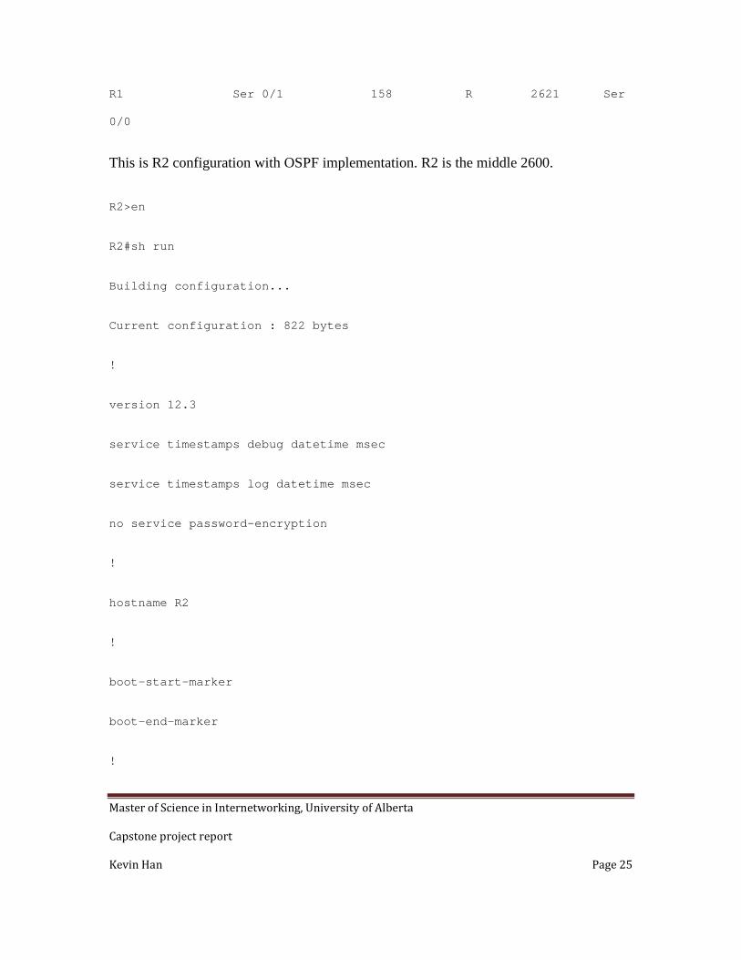
R1 Ser 0/1 158 R 2621 Ser
0/0
This is R2 configuration with OSPF implementation. R2 is the middle 2600.
R2>en
R2#sh run
Building configuration...
Current configuration : 822 bytes
!
version 12.3
service timestamps debug datetime msec
service timestamps log datetime msec
no service password-encryption
!
hostname R2
!
boot-start-marker
boot-end-marker
!

Master of Science in Internetworking, University of Alberta
Capstone project report
Kevin Han Page 26
memory-size iomem 10
no aaa new-model
ip subnet-zero
!
no ip domain lookup
!
ip cef
!
interface FastEthernet0/0
description connecting to the testing host moving between two
locations
ip address 192.168.1.1 255.255.255.0
duplex auto
speed auto
no shut
!
interface Serial0/0
description connecting to router R3 on interface s0/1

Master of Science in Internetworking, University of Alberta
Capstone project report
Kevin Han Page 27
ip address 192.168.8.1 255.255.255.0
clock rate 56000
no shut
!
interface Serial0/1
description connecting to router R1 on interface s0/0
ip address 192.168.5.2 255.255.255.0
clock rate 56000
no shut
!
router ospf 100
log-adjacency-changes
network 192.168.1.0 0.0.0.255 area 0
network 192.168.5.0 0.0.0.255 area 0
network 192.168.8.0 0.0.0.255 area 0
!
ip http server
ip classless

Master of Science in Internetworking, University of Alberta
Capstone project report
Kevin Han Page 28
!
voice-port 1/0/0
!
voice-port 1/0/1
!
line con 0
line aux 0
line vty 0 4
!
end
6.1.3 R3 configuration This is “sh cdp nei” output on R3.
R3#sh cdp nei
Capability Codes: R – Router, T – Trans Bridge, B – Source Route Bridge
S – Switch, H – Host, I – IGMP, r – Repeater
Device ID Local Intrfce Holdtme Capability Platform
Port ID

Master of Science in Internetworking, University of Alberta
Capstone project report
Kevin Han Page 29
R2 Ser 0/1 143 R 2620 Ser
0/0
R4 Fas 0/0 141 R S I 2821 Gig
0/0
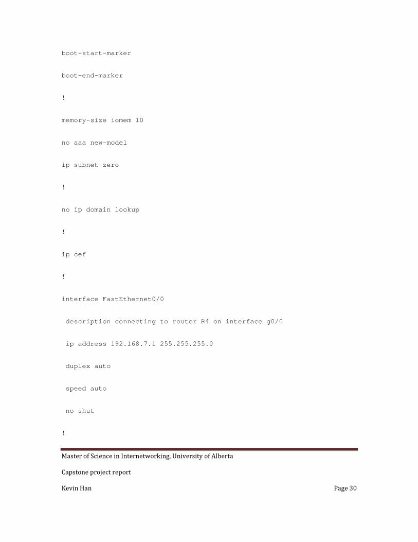
This is R3 configuration with OSPF implementation, R3 is bottom 2600.
R3>en
R3#sh run
Building configuration...
Current configuration : 735 bytes
!
version 12.3
service timestamps debug datetime msec
service timestamps log datetime msec
no service password-encryption
!
hostname R3
!
Master of Science in Internetworking, University of Alberta
Capstone project report
Kevin Han Page 30
boot-start-marker
boot-end-marker
!
memory-size iomem 10
no aaa new-model
ip subnet-zero
!
no ip domain lookup
!
ip cef
!
interface FastEthernet0/0
description connecting to router R4 on interface g0/0
ip address 192.168.7.1 255.255.255.0
duplex auto
speed auto
no shut
!
Master of Science in Internetworking, University of Alberta
Capstone project report
Kevin Han Page 31
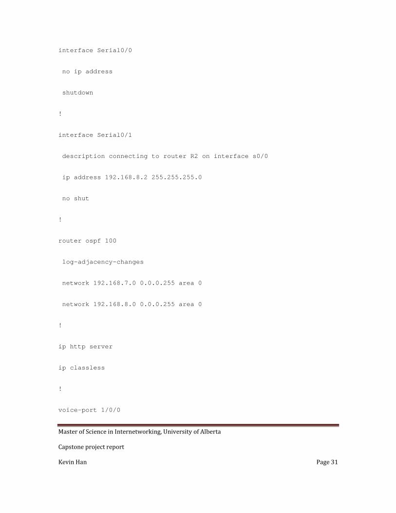
interface Serial0/0
no ip address
shutdown
!
interface Serial0/1
description connecting to router R2 on interface s0/0
ip address 192.168.8.2 255.255.255.0
no shut
!
router ospf 100
log-adjacency-changes
network 192.168.7.0 0.0.0.255 area 0
network 192.168.8.0 0.0.0.255 area 0
!
ip http server
ip classless
!
voice-port 1/0/0
Master of Science in Internetworking, University of Alberta
Capstone project report
Kevin Han Page 32
!
voice-port 1/0/1
!
line con 0
line aux 0
line vty 0 4
!
end
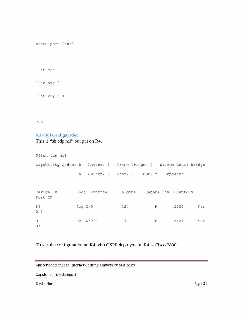
6.1.4 R4 Configuration This is “sh cdp nei” out put on R4.
R4#sh cdp nei
Capability Codes: R – Router, T – Trans Bridge, B – Source Route Bridge
S – Switch, H – Host, I – IGMP, r – Repeater
Device ID Local Intrfce Holdtme Capability Platform Port ID
R3 Gig 0/0 124 R 2620 Fas 0/0
R1 Ser 0/0/0 144 R 2621 Ser 0/1
This is the configuration on R4 with OSPF deployment. R4 is Cisco 2800.
Master of Science in Internetworking, University of Alberta
Capstone project report
Kevin Han Page 33
R4>en
R4#sh run
Building configuration...
Current configuration : 1227 bytes
!
version 12.4
service timestamps debug datetime msec
service timestamps log datetime msec
no service password-encryption
!
hostname R4
!
boot-start-marker
boot-end-marker
!
logging message-counter syslog
!
no aaa new-model
memory-size iomem 10
!
dot11 syslog
ip source-route
!
ip cef

Master of Science in Internetworking, University of Alberta
Capstone project report
Kevin Han Page 34
!
no ipv6 cef
!
multilink bundle-name authenticated
!
voice-card 0
!
archive
log config
hidekeys
!
interface GigabitEthernet0/0
description connecting to router R3 on interface F0/0
ip address 192.168.7.2 255.255.255.0
duplex auto
speed auto
no shut
!
interface GigabitEthernet0/1
no ip address
shutdown
duplex auto
speed auto
!
interface FastEthernet0/1/0

Master of Science in Internetworking, University of Alberta
Capstone project report
Kevin Han Page 35
!
interface FastEthernet0/1/1
!
interface FastEthernet0/1/2
!
interface FastEthernet0/1/3
!
interface Serial0/0/0
description connecting to router R1 on interface s0/1
ip address 192.168.6.2 255.255.255.0
no fair-queue
no shut
!
interface Vlan1
no ip address
!
router ospf 100
log-adjacency-changes
network 192.168.6.0 0.0.0.255 area 0
network 192.168.7.0 0.0.0.255 area 0
!
ip forward-protocol nd
no ip http server
no ip http secure-server
!

Master of Science in Internetworking, University of Alberta
Capstone project report
Kevin Han Page 36
control-plane
!
ccm-manager fax protocol cisco
!
mgcp fax t38 ecm
!
line con 0
line aux 0
line vty 0 4
login
!
scheduler allocate 20000 1000
end
6.2 The following configurations are implemented with IS-IS.
6.2.1 R1 configuration: R1>en
R1#sh run
Building configuration...
Current configuration : 793 bytes
!
version 12.3
service timestamps debug datetime msec
service timestamps log datetime msec
no service password-encryption

Master of Science in Internetworking, University of Alberta
Capstone project report
Kevin Han Page 37
!
hostname R1
!
boot-start-marker
boot-end-marker
!
no aaa new-model
ip subnet-zero
!
!
no ip domain lookup
!
ip cef
!
interface FastEthernet0/0
description connecting to the testing host moving between two locations
ip address 192.168.1.1 255.255.255.0
ip router isis
duplex auto
speed auto
no shut
!
interface Serial0/0
description connecting to router R2 on interface s0/1
ip address 192.168.5.1 255.255.255.0

Master of Science in Internetworking, University of Alberta
Capstone project report
Kevin Han Page 38
no shut
ip router isis
!
interface FastEthernet0/1
no ip address
duplex auto
speed auto
!
interface Serial0/1
description connecting to router R4 on interface s0/0/0
ip address 192.168.6.1 255.255.255.0
no shut
ip router isis
clock rate 56000
!
router isis
net 49.0001.1111.1111.1111.00
is-type level-1-2
!
ip http server
ip classless
!
voice-port 1/0/0
!
voice-port 1/0/1
Master of Science in Internetworking, University of Alberta
Capstone project report
Kevin Han Page 39
!
line con 0
line aux 0
line vty 0 4
!
end
***********************************************************************R1#sh cdp nei
Capability Codes: R – Router, T – Trans Bridge, B – Source Route Bridge
S – Switch, H – Host, I – IGMP, r – Repeater
Device ID Local Intrfce Holdtme Capability Platform Port ID
R2 Ser 0/0 178 R 2620 Ser 0/1
R4 Ser 0/1 174 R S I 2821 Ser 0/0/0
6.2.2 R2 configuration: R2>en
R2#sh run
Building configuration...
Current configuration : 764 bytes
!
version 12.3

Master of Science in Internetworking, University of Alberta
Capstone project report
Kevin Han Page 40
service timestamps debug datetime msec
service timestamps log datetime msec
no service password-encryption
!
hostname R2
!
boot-start-marker
boot-end-marker
!
memory-size iomem 10
no aaa new-model
ip subnet-zero
!
no ip domain lookup
!
ip cef
!
interface FastEthernet0/0
description connecting to the testing host moving between two locations
ip address 192.168.1.1 255.255.255.0
no shut
ip router isis
duplex auto
speed auto
!

Master of Science in Internetworking, University of Alberta
Capstone project report
Kevin Han Page 41
interface Serial0/0
description connecting to router R3 on interface s0/1
ip address 192.168.8.1 255.255.255.0
no shut
ip router isis
clock rate 56000
!
interface Serial0/1
description connecting to router R1 on interface s0/0
ip address 192.168.5.2 255.255.255.0
no shut
ip router isis
clock rate 56000
!
router isis
net 49.0001.2222.2222.2222.00
is-type level-1-2
!
ip http server
ip classless
!
voice-port 1/0/0
!
voice-port 1/0/1
!
Master of Science in Internetworking, University of Alberta
Capstone project report
Kevin Han Page 42
line con 0
line aux 0
line vty 0 4
!
end
R2#sh cdp nei
Capability Codes: R – Router, T – Trans Bridge, B – Source Route Bridge
S – Switch, H – Host, I – IGMP, r – Repeater
Device ID Local Intrfce Holdtme Capability Platform Port ID
R3 Ser 0/0 158 R 2620 Ser 0/1
R1 Ser 0/1 158 R 2621 Ser 0/0
6.2.3 R3 Configuration: R3#en
R3#sh run
Building configuration...
Current configuration : 698 bytes
!
version 12.3
service timestamps debug datetime msec

Master of Science in Internetworking, University of Alberta
Capstone project report
Kevin Han Page 43
service timestamps log datetime msec
no service password-encryption
!
hostname R3
!
boot-start-marker
boot-end-marker
!
memory-size iomem 10
no aaa new-model
ip subnet-zero
!
no ip domain lookup
!
ip cef
!
interface FastEthernet0/0
description connecting to router R4 on interface g0/0
ip address 192.168.7.1 255.255.255.0
no shut
ip router isis
duplex auto
speed auto
!
interface Serial0/0

Master of Science in Internetworking, University of Alberta
Capstone project report
Kevin Han Page 44
no ip address
shutdown
!
interface Serial0/1
description connecting to router R2 on interface s0/0
ip address 192.168.8.2 255.255.255.0
no shut
ip router isis
!
router isis
net 49.0001.3333.3333.3333.00
is-type level-1-2
!
ip http server
ip classless
!
voice-port 1/0/0
!
voice-port 1/0/1
!
line con 0
line aux 0
line vty 0 4
!
end

Master of Science in Internetworking, University of Alberta
Capstone project report
Kevin Han Page 45
R3#sh cdp nei
Capability Codes: R – Router, T – Trans Bridge, B – Source Route Bridge
S – Switch, H – Host, I – IGMP, r – Repeater
Device ID Local Intrfce Holdtme Capability Platform Port ID
R2 Ser 0/1 143 R 2620 Ser 0/0
R4 Fas 0/0 141 R S I 2821 Gig 0/0
6.2.4 R4 Configuration: R4#en
R4#sh run
Building configuration...
Current configuration : 1190 bytes
!
version 12.4
service timestamps debug datetime msec
service timestamps log datetime msec
no service password-encryption
!
hostname R4
!

Master of Science in Internetworking, University of Alberta
Capstone project report
Kevin Han Page 46
boot-start-marker
boot-end-marker
!
logging message-counter syslog
!
no aaa new-model
memory-size iomem 10
!
dot11 syslog
ip source-route
!
ip cef
!
no ipv6 cef
!
multilink bundle-name authenticated
!
voice-card 0
!
archive
log config
hidekeys
!
interface GigabitEthernet0/0
description connecting to router R3 on interface F0/0

Master of Science in Internetworking, University of Alberta
Capstone project report
Kevin Han Page 47
ip address 192.168.7.2 255.255.255.0
no shut
ip router isis
duplex auto
speed auto
!
interface GigabitEthernet0/1
no ip address
shutdown
duplex auto
speed auto
!
interface FastEthernet0/1/0
!
interface FastEthernet0/1/1
!
interface FastEthernet0/1/2
!
interface FastEthernet0/1/3
!
interface Serial0/0/0
description connecting to router R1 on interface s0/1
ip address 192.168.6.2 255.255.255.0
no shut
ip router isis

Master of Science in Internetworking, University of Alberta
Capstone project report
Kevin Han Page 48
no fair-queue
!
interface Vlan1
no ip address
!
router isis
net 49.0001.4444.4444.4444.00
is-type level-1-2
!
ip forward-protocol nd
no ip http server
no ip http secure-server
!
control-plane
!
ccm-manager fax protocol cisco
!
mgcp fax t38 ecm
!
line con 0
line aux 0
line vty 0 4
login
!
scheduler allocate 20000 1000

Master of Science in Internetworking, University of Alberta
Capstone project report
Kevin Han Page 49
end
R4#sh cdp nei
Capability Codes: R – Router, T – Trans Bridge, B – Source Route Bridge
S – Switch, H – Host, I – IGMP, r – Repeater
Device ID Local Intrfce Holdtme Capability Platform Port ID
R3 Gig 0/0 124 R 2620 Fas 0/0
R1 Ser 0/0/0 144 R 2621 Ser 0/1
Master of Science in Internetworking, University of Alberta
Capstone project report
Kevin Han Page 50
Chapter 7 Test results
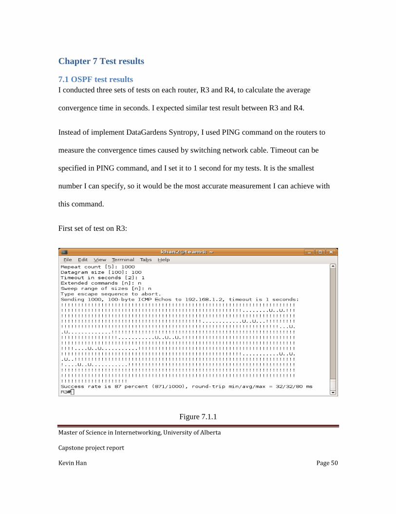
7.1 OSPF test results I conducted three sets of tests on each router, R3 and R4, to calculate the average
convergence time in seconds. I expected similar test result between R3 and R4.
Instead of implement DataGardens Syntropy, I used PING command on the routers to
measure the convergence times caused by switching network cable. Timeout can be
specified in PING command, and I set it to 1 second for my tests. It is the smallest
number I can specify, so it would be the most accurate measurement I can achieve with
this command.
First set of test on R3:
Figure 7.1.1
Master of Science in Internetworking, University of Alberta
Capstone project report
Kevin Han Page 51
We had 13, 19, 20, 19, 19, 20, 19 seconds convergence times.
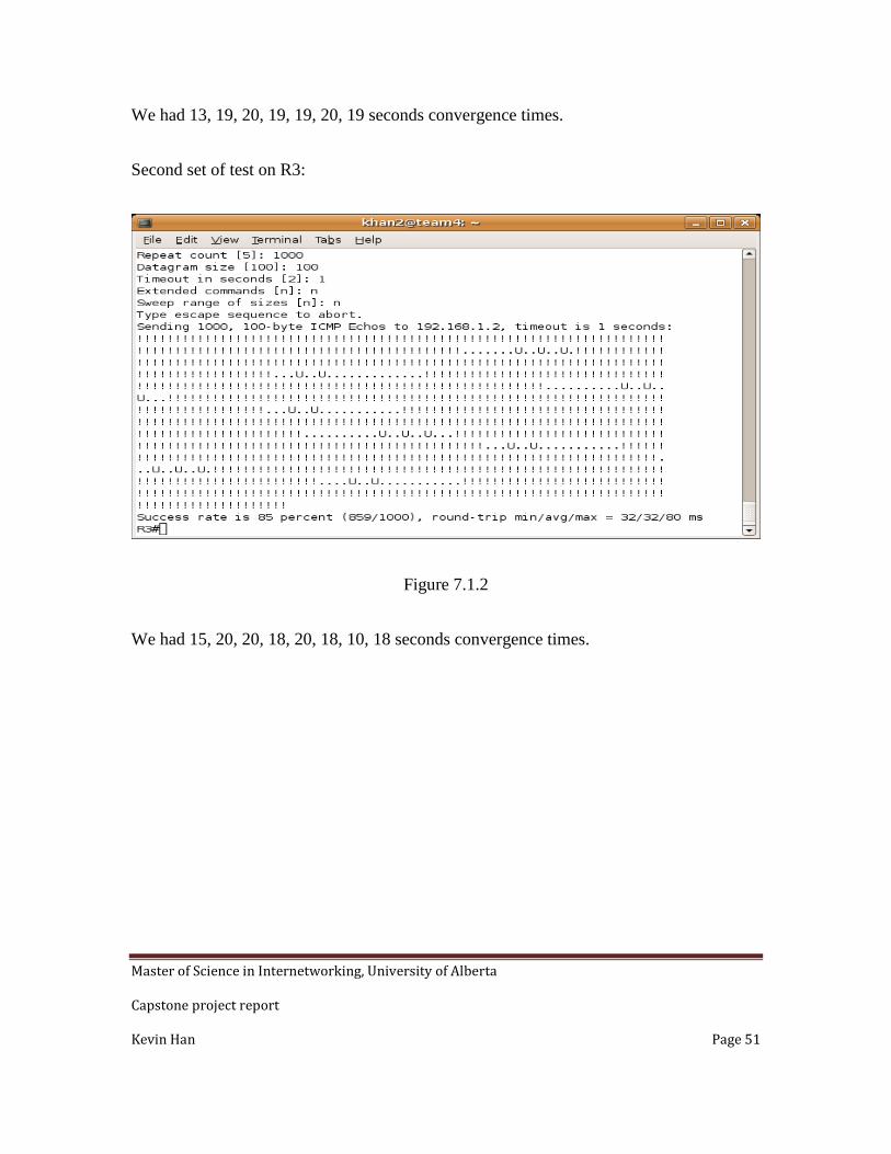
Second set of test on R3:
Figure 7.1.2
We had 15, 20, 20, 18, 20, 18, 10, 18 seconds convergence times.

Master of Science in Internetworking, University of Alberta
Capstone project report
Kevin Han Page 52
Third set of test on R3:
Figure 7.1.3
The convergence times were 10, 20, 8, 19, 8 seconds. The average is about 17 seconds on
R3.

Master of Science in Internetworking, University of Alberta
Capstone project report
Kevin Han Page 53
Overall average convergence time was 17 seconds.
Test1
convergence time
Test2
convergence time
Test3
convergence time
Average
convergence time
13 15 10
19 20 20
20 20 8
19 18 19
19 20 8
20 18
19 10
18 17
Table 7.1.1

Master of Science in Internetworking, University of Alberta
Capstone project report
Kevin Han Page 54
First set of test on R4.
Figure 7.1.4
The convergence times were 13, 19, 19, 19, 20, 18, 20 seconds.
Second set of test on R4:
Figure 7.1.5

Master of Science in Internetworking, University of Alberta
Capstone project report
Kevin Han Page 55
The convergence times were 15, 19, 19, 19, 19, 17, 12, 20 seconds.
The third set of test on R4:
Figure 7.1.6
The convergence times were 10, 19, 23, 20, 23, 22, 22, 22, 23 second.

Master of Science in Internetworking, University of Alberta
Capstone project report
Kevin Han Page 56
The average is about 19 second on R4. The average convergence time is 2 seconds longer
than on R3.
Overall average convergence time was 19 seconds.
Test1
convergence time
Test2
convergence time
Test3
convergence time
Average
convergence time
13 15 10
19 19 19
19 19 23
19 19 20
20 19 23
18 17 22
20 12 22
20 22
23 19
Table 7.1.2
Master of Science in Internetworking, University of Alberta
Capstone project report
Kevin Han Page 57
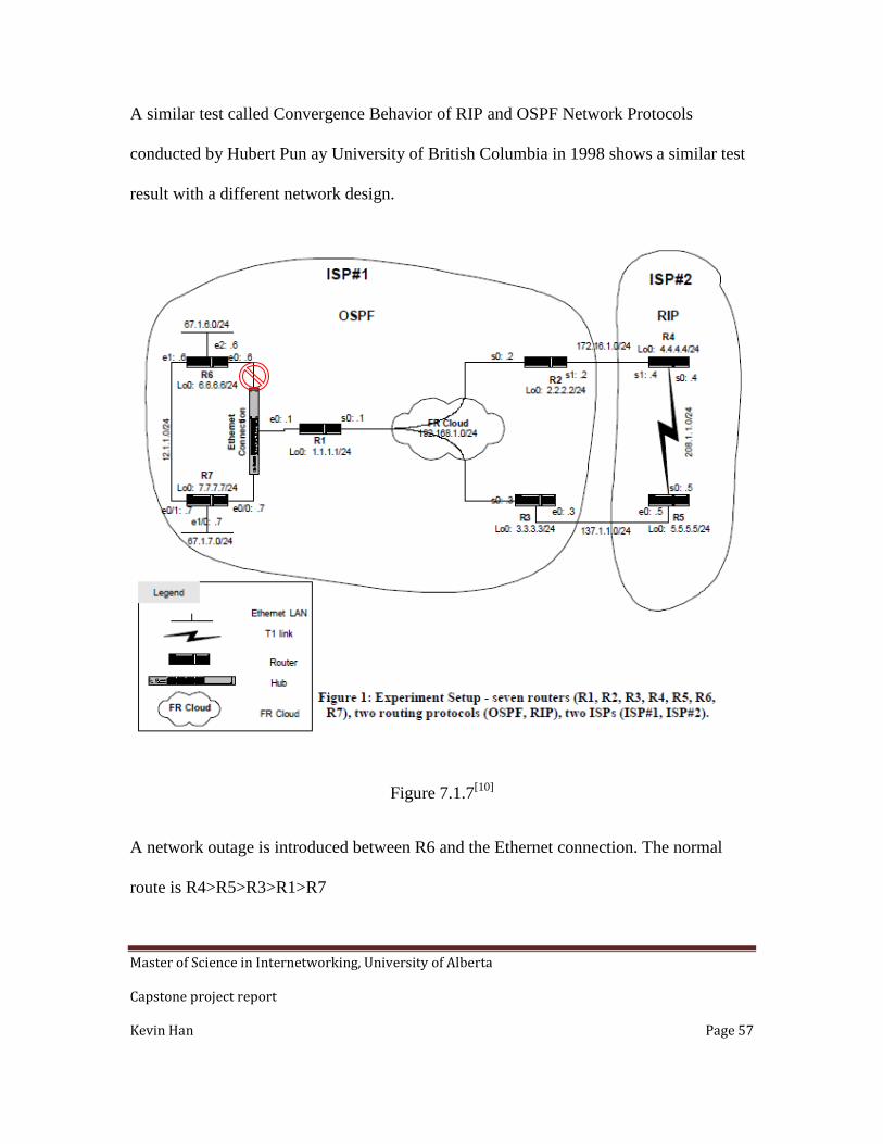
A similar test called Convergence Behavior of RIP and OSPF Network Protocols
conducted by Hubert Pun ay University of British Columbia in 1998 shows a similar test
result with a different network design.
Figure 7.1.7[10]
A network outage is introduced between R6 and the Ethernet connection. The normal
route is R4>R5>R3>R1>R7
Master of Science in Internetworking, University of Alberta
Capstone project report
Kevin Han Page 58
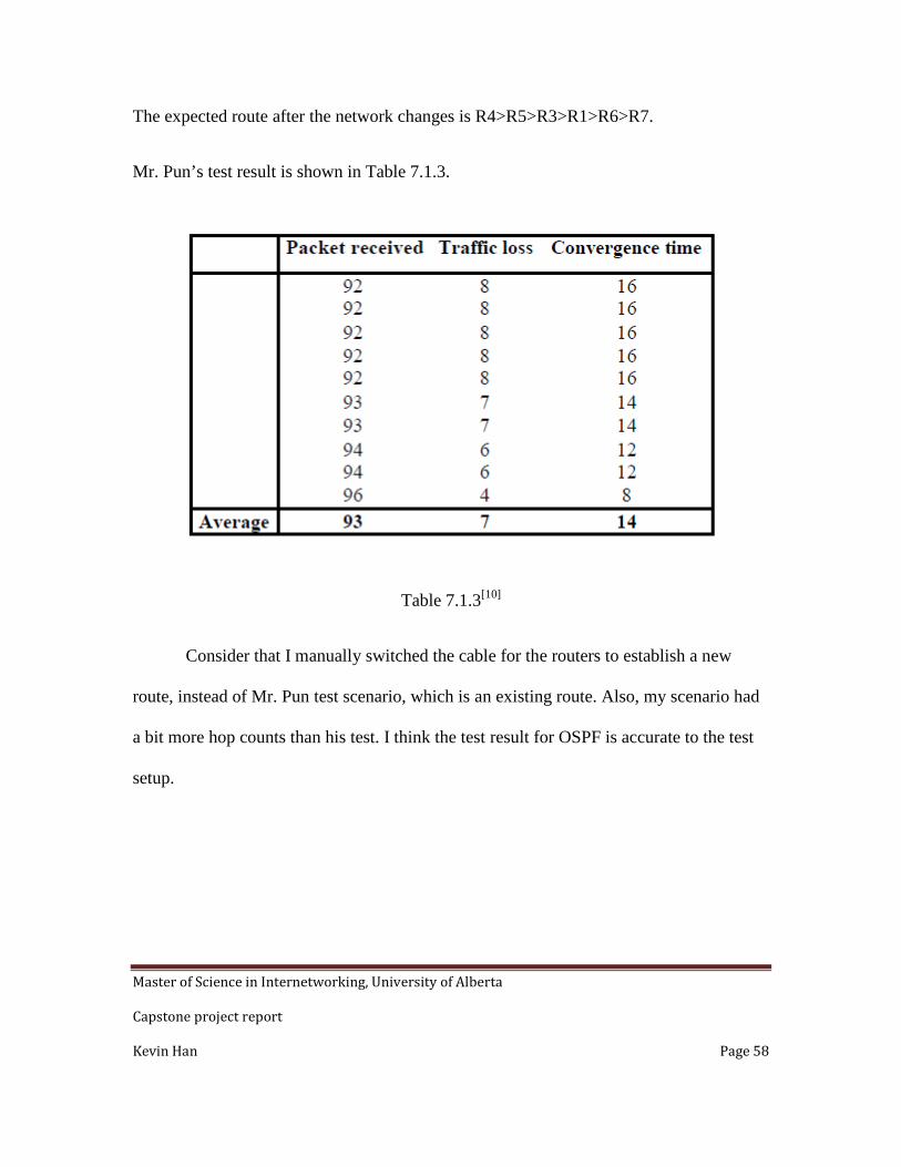
The expected route after the network changes is R4>R5>R3>R1>R6>R7.
Mr. Pun’s test result is shown in Table 7.1.3.
Table 7.1.3[10]
Consider that I manually switched the cable for the routers to establish a new
route, instead of Mr. Pun test scenario, which is an existing route. Also, my scenario had
a bit more hop counts than his test. I think the test result for OSPF is accurate to the test
setup.

Master of Science in Internetworking, University of Alberta
Capstone project report
Kevin Han Page 59
7.2 IS-IS test results. I also conducted three sets of test on both R3 and R4.
The first set of test on R3.
Figure 7.2.1
The convergence times were 6, 19, 10, 8 seconds.
IS-IS on R3 test 2:

Master of Science in Internetworking, University of Alberta
Capstone project report
Kevin Han Page 60
Figure 7.2.2
The convergence times were 7, 10, 6, 21, 10, 9, 6, 9, 6 seconds.
IS-IS on R3 test 3:
Figure 7.2.3
The convergence times were 8, 8, 5, 7, 5, 9, 5, 9, 5, 9 second.

Master of Science in Internetworking, University of Alberta
Capstone project report
Kevin Han Page 61
The average convergence time on R3 was 9 seconds.
Test1
convergence time
Test2
convergence time
Test3
convergence time
Average
convergence time
6 7 8
19 10 8
10 6 5
8 21 7
10 5
9 9
6 5
9 9
6 5
9 9
Table 7.2.1

Master of Science in Internetworking, University of Alberta
Capstone project report
Kevin Han Page 62
IS-IS on R4 test 1:
Figure 7.2.4
The convergence times were 17, 12, 14, 5 seconds.
IS-IS on R4 test 2:
Figure 7.2.5

Master of Science in Internetworking, University of Alberta
Capstone project report
Kevin Han Page 63
The convergence times were 11, 7, 16, 14, 12, 6, 10, 6, 9 seconds.
IS-IS on R4 test 3:
Figure 7.2.6
The convergence times were 12, 9, 9, 8, 9, 9, 9, 9, 9, 9, 23 seconds. The overall average
convergence time on R4 was 11 seconds. The delay was 2 seconds longer than R3. The
difference was consistent with OSPF test result. IS-IS seems to have a bit better
convergence time comparing to OSPF.

Master of Science in Internetworking, University of Alberta
Capstone project report
Kevin Han Page 64
Test1
convergence time
Test2
convergence time
Test3
convergence time
Average
convergence time
17 11 12
12 7 9
14 16 9
5 14 8
12 9
6 9
10 9
6 9
9 9
9
23 11
Table 7.2.2
Master of Science in Internetworking, University of Alberta
Capstone project report
Kevin Han Page 65
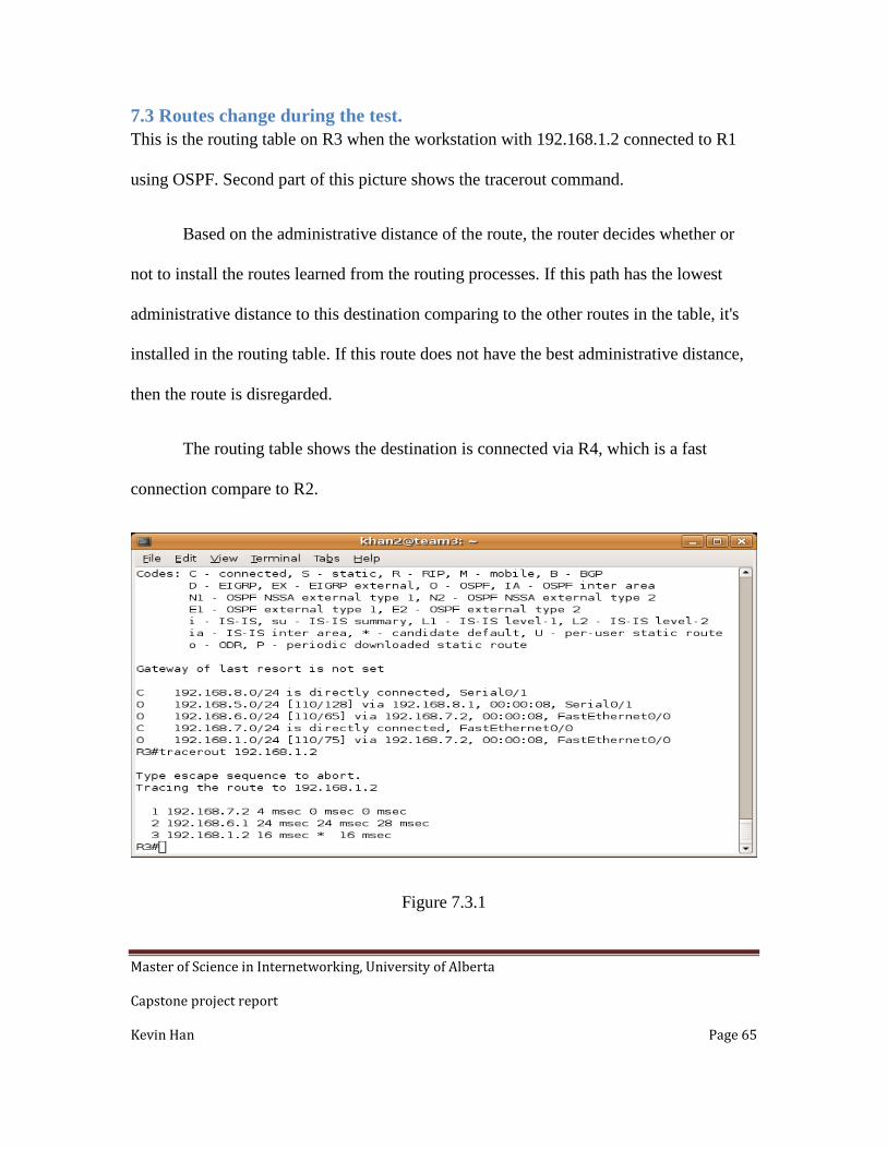
7.3 Routes change during the test. This is the routing table on R3 when the workstation with 192.168.1.2 connected to R1
using OSPF. Second part of this picture shows the tracerout command.
Based on the administrative distance of the route, the router decides whether or
not to install the routes learned from the routing processes. If this path has the lowest
administrative distance to this destination comparing to the other routes in the table, it's
installed in the routing table. If this route does not have the best administrative distance,
then the route is disregarded.
The routing table shows the destination is connected via R4, which is a fast
connection compare to R2.
Figure 7.3.1

Master of Science in Internetworking, University of Alberta
Capstone project report
Kevin Han Page 66
Figure 7.3.2 shows the routing table on R3 and the tracerout command when the
workstation is switched to R2.
Figure 7.3.2
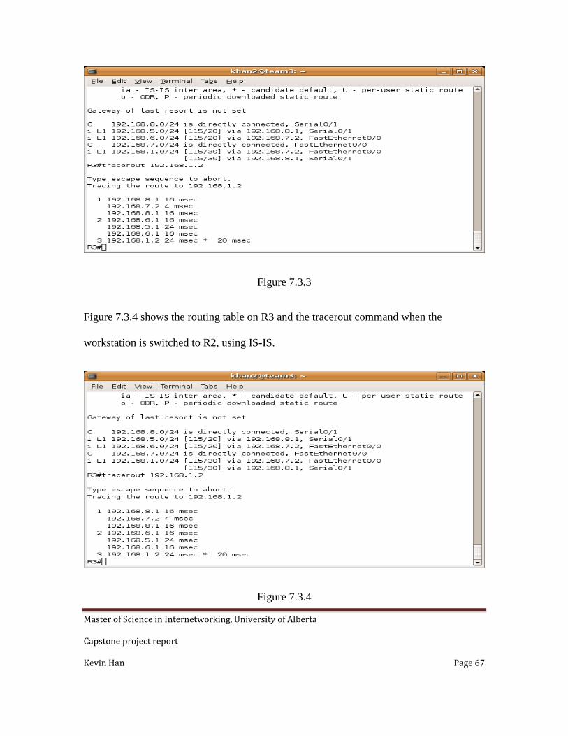
The following is the routing table on R3 when the workstation is connected to R1 in IS-
IS.
The routing table shows there are two routes to the destination via both R4 and R2.
Master of Science in Internetworking, University of Alberta
Capstone project report
Kevin Han Page 67
Figure 7.3.3
Figure 7.3.4 shows the routing table on R3 and the tracerout command when the
workstation is switched to R2, using IS-IS.
Figure 7.3.4

Master of Science in Internetworking, University of Alberta
Capstone project report
Kevin Han Page 68
The Figure 7.3.5 shows the routing table on R4 when workstation is connected to R1
using OSPF. The routing table tells us the destination is via R1, the shortest path.
Figure7.3.5
Figure 7.3.6 shows the same scenario in IS-IS configuration.
Figure 7.3.6

Master of Science in Internetworking, University of Alberta
Capstone project report
Kevin Han Page 69
Figure 7.3.7 show the routing table on R4 and tracerout command when workstation is
connected to R2 in OSPF configuration.
Figure 7.3.7
Figure 7.3.8 shows a similar scenario in IS-IS configuration.
Figure 7.3.8

Master of Science in Internetworking, University of Alberta
Capstone project report
Kevin Han Page 70
Chapter 8 Things to consider and conclusion
Our test results indicate anycast is a viable solution for DataGardens Syntropy.
Both OSPF and IS-IS provide very short network convergence time. They provide better
reconnection time than DNS solution.
To further improve convergence time, we can manipulate the default timers, by
reducing the default timers to five seconds or even less. However, short default timers
mean more network traffic. We must assess the network health and condition before we
increase or decrease the default timers.
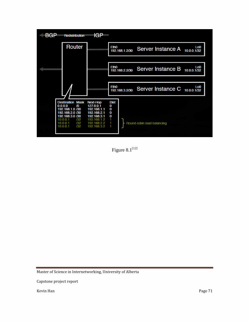
Another factor needs to be considered is the network design is in a disastrous
situation, we might move all the virtual servers to a back up location. However during
regular maintenance, we may only want to move one or two servers. Very often, the IP
addresses on these servers are in the same IP subnets. That creates challenges when we
migrating these servers to another location and still wanting to maintain the same IP
addresses. Usually this back-up location is allocated with another set of IP subnet. To
resolve this, we can create a loopback interface on the server, and assign a permanent IP
address with a /32 subnet mask to this loopback interface. We also need to enable routing
capability on the server, so the router knows how to reach this loopback interface. Figure
8.1 demonstrate this idea.
Master of Science in Internetworking, University of Alberta
Capstone project report
Kevin Han Page 71
Figure 8.1[12]

Master of Science in Internetworking, University of Alberta
Capstone project report
Kevin Han Page 72
Reference [1]. VMware ESX is a component offered by VMware, Inc.
[2]. VMotion is a component offered by VMware, Inc.
[3]. These four points are quoted from VMware website
[4]. Wikipedia definition
[5]. T.Hardie, Distributing Authoritative Name Servers via Shared Unicast
Addresses, RFC 3258, Apr.2002.
[6]. http://hinrg.cs.jhu.edu/Main/DNS
[7]. Images from Wikipedia website, these images have been used by many
articles, can’t locate the original source.
[8]. RFC 2328
[9]. Reducing Failure Detection Times in IS-IS Networks by CISCO
SYSTEMS
[10]. Convergence Behavior of RIP and OSPF Network Protocol by
Hubert Pun
[11]. RFC 1195
[12]. Best Practices in IPv4 Anycast Routing by Bill Woodcock