minolta dynax 9
DESCRIPTION
Dynax 9 / MAXXUM 9 (Alpha 9) - INSTRUCTION MANUALTRANSCRIPT
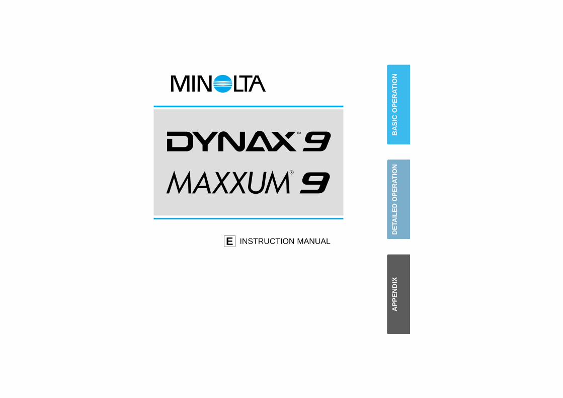
INSTRUCTION MANUALE
BA
SIC
OP
ER
AT
ION
DE
TAIL
ED
OP
ER
ATI
ON
AP
PE
ND
IX
1
FOR PROPER AND SAFE USE
Read and understand all warnings and cautions before using this product.
WARNINGBatteries may become hot or explode due to improper use.
• Use only the batteries specified in this instruction manual.• Do not install the batteries with the polarity (+/–) reversed.• Do not subject batteries to fire or high temperatures.• Do not attempt to recharge, short, or disassemble.• Do not mix batteries of different types, brands, or ages.• Follow local regulations for battery disposal. Tape over lithium battery contacts before
disposal.
Use caution, accidents may occur when using this product near young children.
Keep batteries and other things that could be swallowed away from young children.Contact a doctor immediately if an object is swallowed.
Immediately remove the batteries and discontinue use if…• the camera is dropped or subjected to an impact in which the interior is exposed.• the camera emits a strange smell, heat, or smoke.
Do not disassemble. Electric shock may occur if a high voltage circuit inside thecamera is touched. Take your camera to a Minolta Service Facility when repairs arerequired.
Do not look directly at the sun through the viewfinder.
CAUTIONDo not allow a camera lens to point directly at the sun. Fire may occur if sunlightcomes to focus on a flammable surface. Replace the lens cap when the product isnot being used.
The ultimate tool for creative professionals and advanced amateurs alike, theMaxxum/Dynax 9 has been designed with precission in mind to help you captureyour photographic vision. As you use the Maxxum/Dynax 9, you will find that itsperformance and reliability compliment your own photographic expertise and inraising your skills to a higher level.
In addition to its high durability zinc and stainless steel body, the Maxxum/Dynax 9boasts the following features:
• A top shutter speed of 1/12,000 sec. and top x-sync speed of 1/300 sec.• High speed autofocus with omni-dimensional Predictive Focus Control
and a maximum framing rate of 4.5 frames/sec with autofocus trackingin continuous focus mode. (5.5 frames/sec in manual focus mode)
• 100% viewfinder• 1/3 and 1/2 EV exposure compensation increments.• Data Memory storage of exposure information.• 21 Custom Functions to tailor the camera to your personal shooting style
This manual has been designed to help you understand the operation of yourcamera and its functions. Please familiarize yourself with the names of the controlsand their locations on the camera, then read the Getting Started and BasicOperation sections. Once you’ve mastered basic operation, move on to the DetailedOperation section to expand your expertise.
This device complies with Part 15 of the FCC Rules. Operation is subject to the following two condi-tions: (1) This device may not cause harmful interference, and (2) this device must accept any inter-ference received, including interference that may cause undesired operation. Changes or modifica-tions not approved by the party responsible for compliance could void the user's authority to operatethe equipment. This equipment has been tested and found to comply with the limits for a Class B digi-tal device, pursuant to Part 15 of the FCC Rules. These limits are designed to provide reasonableprotection against harmful interference in a residential installation. This equipment generates, usesand can radiate radio frequency energy and, if not installed and used in accordance with the instruc-tions, may cause harmful interference to radio communications. However, there is no guarantee thatinterference will not occur in a particular installation. If this equipment does cause harmful interferenceto radio or television reception, which can be determined by turning the equipment off and on, theuser is encouraged to try to correct the interference by one or more of the following measures:
• Reorient or relocate the receiving antenna.• Increase the separation between the equipment and the receiver.• Connect the equipment to an outlet on a circuit different from that to which the receiver is
connected.• Consult the dealer or an experienced radio/TV technician for help.
This Class B digital apparatus complies with Canadian ICES-003.
This mark on your camera certifies that this camera meets the requirements ofthe EU (European Union) concerning interference causing equipment regulations.CE stands for Conformité Européenne (European Conformity).
2 3
Loading Film..........................................15Taking Pictures in Full-Auto ..................18
Focus Signals ....................................19Special Focus Situations.......................20Focus Hold ............................................21
FOCUSPredictive Focus Control .......................27Autofocus Modes ..................................28Wide Focus Area...................................30Local Focus Area ..................................31AF Lock .................................................32Manual Focus........................................33AF Illuminator ........................................34
Table of Contents ....................................2Names of Parts .......................................4
GETTING STARTED
BASIC OPERATION
DETAILED OPERATION
DRIVEAdvance Mode ......................................54Self Timer ..............................................56Exposure Bracketing .............................58Multiple Exposure..................................60
ADDITIONAL FEATURESEye-Start ...............................................76Depth-of Field Preview..........................77Taking Time Exposures.........................78Remote Release Terminal.....................80PC Terminal...........................................81Data Panel Illuminator...........................82
TABLE OF CONTENTS
Accessory Information..........................104Exposure Warnings ..............................107
Strap........................................................8Diopter Adjustment .................................9
APPENDIX
Batteries ................................................10Lens.......................................................12
Handling the Camera ............................13
Using the Built-in FlashOperation...........................................22Flash Signals .....................................22Flash Range ......................................23Lens Shadowing ................................23
Rewinding the FilmAutomatic Rewind..............................24Manual Rewind..................................24
EXPOSUREP-Mode..................................................36A-Mode..................................................37S-Mode..................................................39M-Mode .................................................41
METERINGSelectable Metering
14 Segment Metering ........................45Spot Metering ....................................46Center Weighted Metering.................47
AE Lock.................................................48Exposure Compensation.......................50Setting the ISO Manually ......................52
FLASHFour-Segment Flash Metering ..............63Slow Sync .............................................64Rear-Flash Sync ...................................65High Speed Sync ..................................66
Flash Compensation .............................67Flash Bracketing ...................................68Wireless/Remote Off-Camera Flash .....70
SPECIAL FUNCTIONSData Memory
Selecting............................................84 Overwriting.........................................86Recalling Data ...................................87Deleting Stored Data .........................90
Custom FunctionsSetting................................................91Details................................................92
Trouble Shooting ..................................108Care and Storage.................................110
Specifications .......................................112

54
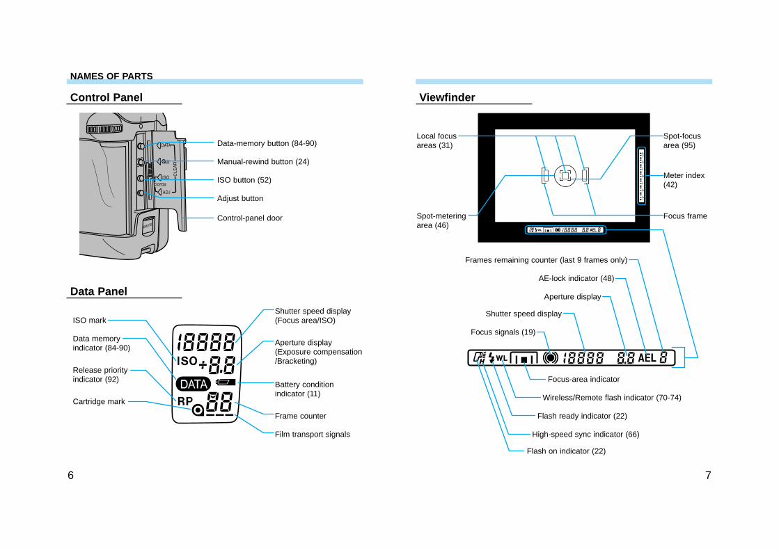
NAMES OF PARTS
For information on specific parts, refer to the page numbers shown in parenthesis.
BodyExposuremode dial (36-43)
Data Panel
Rear control dial
Shutter-releasebutton
Frontcontrol dial
Built-in flash* (22-23)
Exposure-compensationdial lock (50)
Exposure-compensationdial (50)
Flashcompensationdial (67)
Accessory shoe
Drive-mode lever (54)
AF Illuminator /Self-timer lamp(34, 56)
Grip sensor (76)
Depth-of-fieldpreview button (77)
Lens mount (12)
Mirror*
AF mode dial (28)
Focus-mode switch (33)
Lens release (12)
Mountingindex
Lens contacts*
Battery-chamber lock (10)
Battery-chamber door (10)
Vertical control grip contacts(104)
Tripod socket
Diopteradjustment dial (9)
Viewfinder*
Eyepiece cup
Eyepiece shutterlever (79)
Main switch
Eyepiecesensor* (76)
Film window
Eye-start switch (76)
Flash-mode switchAF button (32)
AE-lock button (48)
Data-panelilluminator (82)
Metering-modeswitch (45-47)
PC terminal(81)
Back-coverrelease (15)
Remote-controlterminal (80)
Strap eyelet
* Do not touch
Flash-compensationdial lever (67)
Dirve modedial (54-61)
76
Data Panel
ViewfinderControl Panel
Data-memory button (84-90)
Manual-rewind button (24)
ISO button (52)
Adjust button
Control-panel door
ISO mark
Data memory indicator (84-90)
Release priorityindicator (92)
Cartridge mark
Shutter speed display(Focus area/ISO)
Aperture display(Exposure compensation/Bracketing)
Battery conditionindicator (11)
Frame counter
Film transport signals
Focus frame
Local focusareas (31)
Spot-meteringarea (46)
Spot-focusarea (95)
Flash on indicator (22)
Flash ready indicator (22)
High-speed sync indicator (66)
Wireless/Remote flash indicator (70-74)
Focus-area indicator
Focus signals (19)
Shutter speed display
Aperture display
AE-lock indicator (48)
Frames remaining counter (last 9 frames only)
Meter index(42)
NAMES OF PARTS
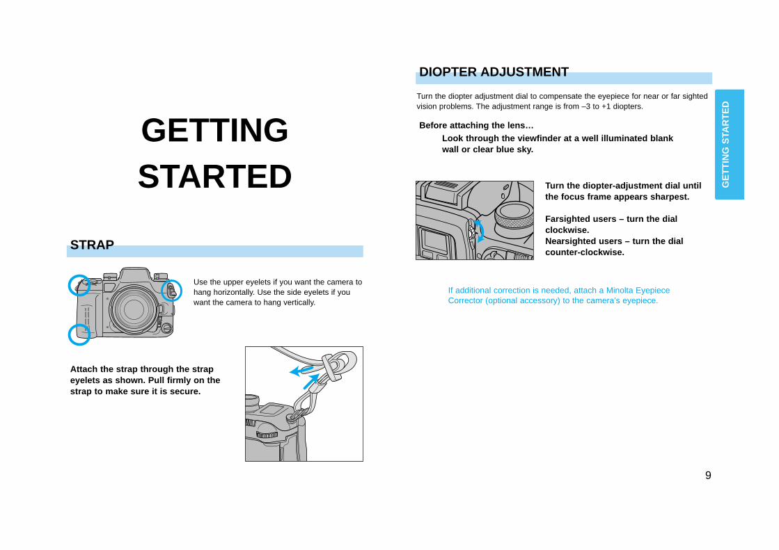
Use the upper eyelets if you want the camera tohang horizontally. Use the side eyelets if youwant the camera to hang vertically.
9
DIOPTER ADJUSTMENT
Turn the diopter adjustment dial to compensate the eyepiece for near or far sightedvision problems. The adjustment range is from –3 to +1 diopters.
Turn the diopter-adjustment dial untilthe focus frame appears sharpest.
Farsighted users – turn the dialclockwise.Nearsighted users – turn the dialcounter-clockwise.
Before attaching the lens…Look through the viewfinder at a well illuminated blankwall or clear blue sky.
If additional correction is needed, attach a Minolta EyepieceCorrector (optional accessory) to the camera’s eyepiece.
GETTING STARTED
Attach the strap through the strapeyelets as shown. Pull firmly on thestrap to make sure it is secure.
GE
TT
ING
STA
RT
ED
STRAP
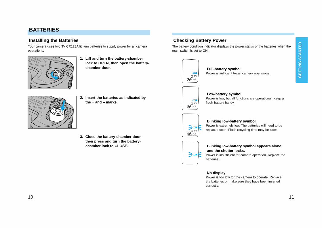
The battery condition indicator displays the power status of the batteries when themain switch is set to ON.
Full-battery symbolPower is sufficient for all camera operations.
Low-battery symbolPower is low, but all functions are operational. Keep afresh battery handy.
Blinking low-battery symbolPower is extremely low. The batteries will need to bereplaced soon. Flash recycling time may be slow.
Blinking low-battery symbol appears aloneand the shutter locks.
Power is insufficient for camera operation. Replace thebatteries.
1110
BATTERIES
Installing the BatteriesYour camera uses two 3V CR123A lithium batteries to supply power for all cameraoperations.
1. Lift and turn the battery-chamberlock to OPEN, then open the battery-chamber door.
2. Insert the batteries as indicated bythe + and – marks.
3. Close the battery-chamber door,then press and turn the battery-chamber lock to CLOSE.
Checking Battery Power
No displayPower is too low for the camera to operate. Replacethe batteries or make sure they have been insertedcorrectly.
GE
TT
ING
STA
RT
ED
1312
LENS
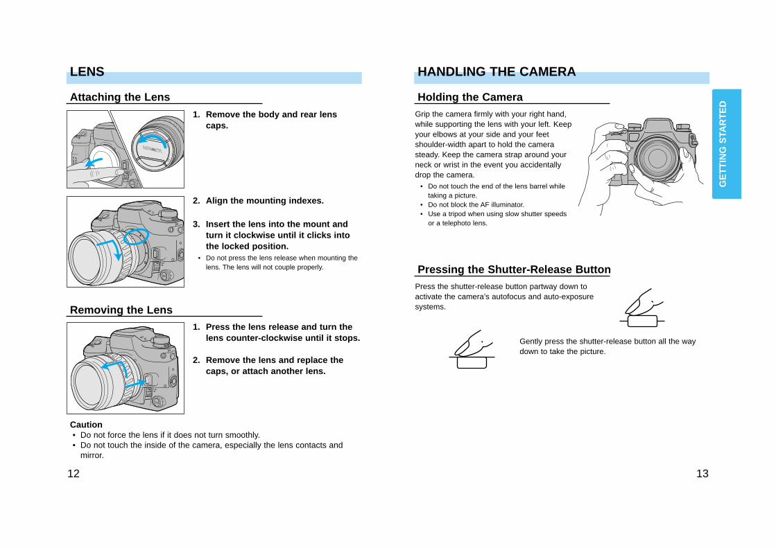
Attaching the Lens
1. Remove the body and rear lenscaps.
2. Align the mounting indexes.
3. Insert the lens into the mount andturn it clockwise until it clicks intothe locked position.
• Do not press the lens release when mounting thelens. The lens will not couple properly.
Removing the Lens1. Press the lens release and turn the
lens counter-clockwise until it stops.
2. Remove the lens and replace thecaps, or attach another lens.
Caution• Do not force the lens if it does not turn smoothly.• Do not touch the inside of the camera, especially the lens contacts and
mirror.
Grip the camera firmly with your right hand,while supporting the lens with your left. Keepyour elbows at your side and your feetshoulder-width apart to hold the camerasteady. Keep the camera strap around yourneck or wrist in the event you accidentallydrop the camera.
• Do not touch the end of the lens barrel whiletaking a picture.
• Do not block the AF illuminator.• Use a tripod when using slow shutter speeds
or a telephoto lens.
HANDLING THE CAMERA
Holding the Camera
Pressing the Shutter-Release ButtonPress the shutter-release button partway down toactivate the camera’s autofocus and auto-exposuresystems.
Gently press the shutter-release button all the waydown to take the picture.
GE
TT
ING
STA
RT
ED
1514
BASICOPERATION
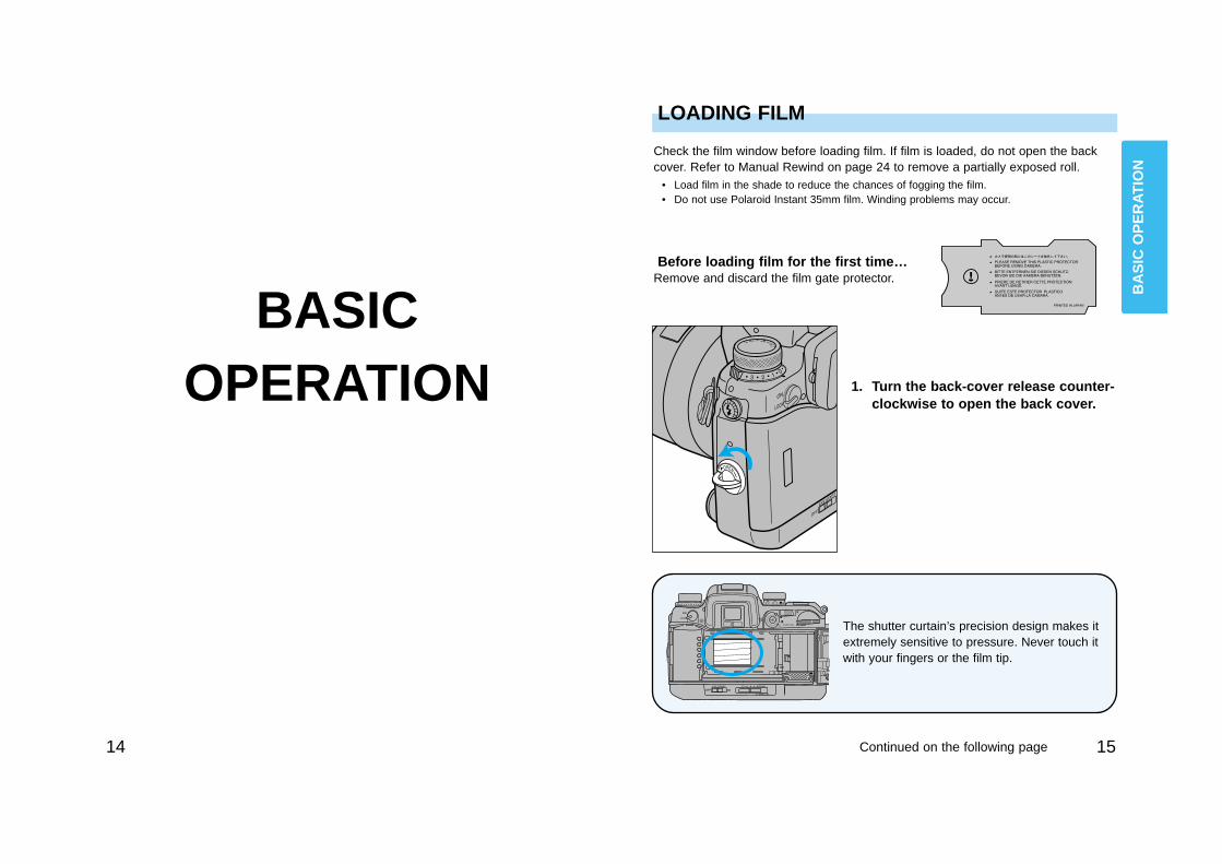
Before loading film for the first time…Remove and discard the film gate protector.
LOADING FILM
Check the film window before loading film. If film is loaded, do not open the backcover. Refer to Manual Rewind on page 24 to remove a partially exposed roll.
• Load film in the shade to reduce the chances of fogging the film.• Do not use Polaroid Instant 35mm film. Winding problems may occur.
1. Turn the back-cover release counter-clockwise to open the back cover.
The shutter curtain’s precision design makes itextremely sensitive to pressure. Never touch itwith your fingers or the film tip.
BA
SIC
OP
ER
AT
ION
Continued on the following page
1716
LOADING FILM
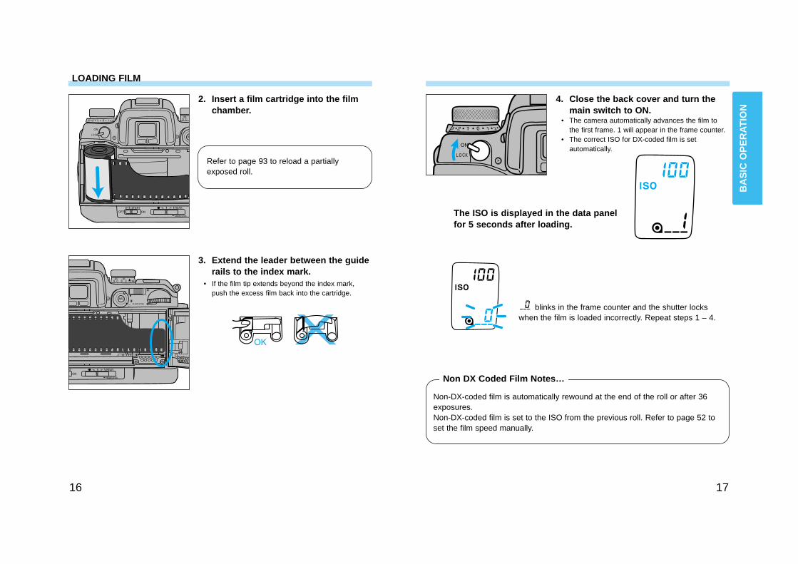
2. Insert a film cartridge into the filmchamber.
3. Extend the leader between the guiderails to the index mark.
• If the film tip extends beyond the index mark,push the excess film back into the cartridge.
4. Close the back cover and turn themain switch to ON.
• The camera automatically advances the film tothe first frame. 1 will appear in the frame counter.
• The correct ISO for DX-coded film is setautomatically.
blinks in the frame counter and the shutter lockswhen the film is loaded incorrectly. Repeat steps 1 – 4.
Non-DX-coded film is automatically rewound at the end of the roll or after 36exposures.Non-DX-coded film is set to the ISO from the previous roll. Refer to page 52 toset the film speed manually.
Non DX Coded Film Notes…
The ISO is displayed in the data panelfor 5 seconds after loading.
Refer to page 93 to reload a partiallyexposed roll.
BA
SIC
OP
ER
AT
ION
1918
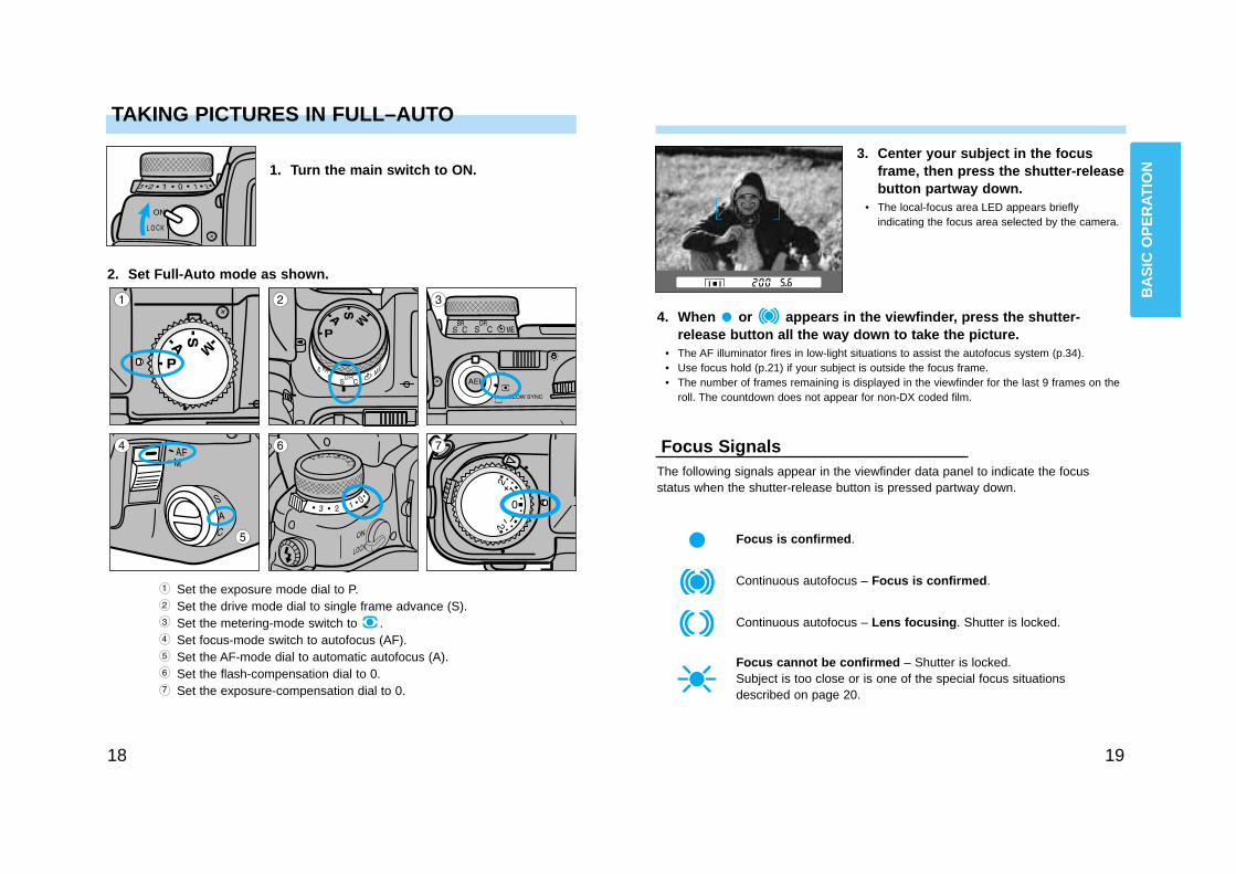
TAKING PICTURES IN FULL–AUTO
1. Turn the main switch to ON.3. Center your subject in the focus
frame, then press the shutter-releasebutton partway down.
• The local-focus area LED appears brieflyindicating the focus area selected by the camera.
4. When or appears in the viewfinder, press the shutter-release button all the way down to take the picture.
• The AF illuminator fires in low-light situations to assist the autofocus system (p.34).• Use focus hold (p.21) if your subject is outside the focus frame.• The number of frames remaining is displayed in the viewfinder for the last 9 frames on the
roll. The countdown does not appear for non-DX coded film.
The following signals appear in the viewfinder data panel to indicate the focusstatus when the shutter-release button is pressed partway down.
Focus is confirmed.
Continuous autofocus – Focus is confirmed.
Continuous autofocus – Lens focusing. Shutter is locked.
Focus cannot be confirmed – Shutter is locked.Subject is too close or is one of the special focus situationsdescribed on page 20.
Focus Signals
2. Set Full-Auto mode as shown.
Set the exposure mode dial to P.Set the drive mode dial to single frame advance (S).Set the metering-mode switch to .Set focus-mode switch to autofocus (AF).Set the AF-mode dial to automatic autofocus (A).Set the flash-compensation dial to 0.Set the exposure-compensation dial to 0.
BA
SIC
OP
ER
AT
ION
20 21
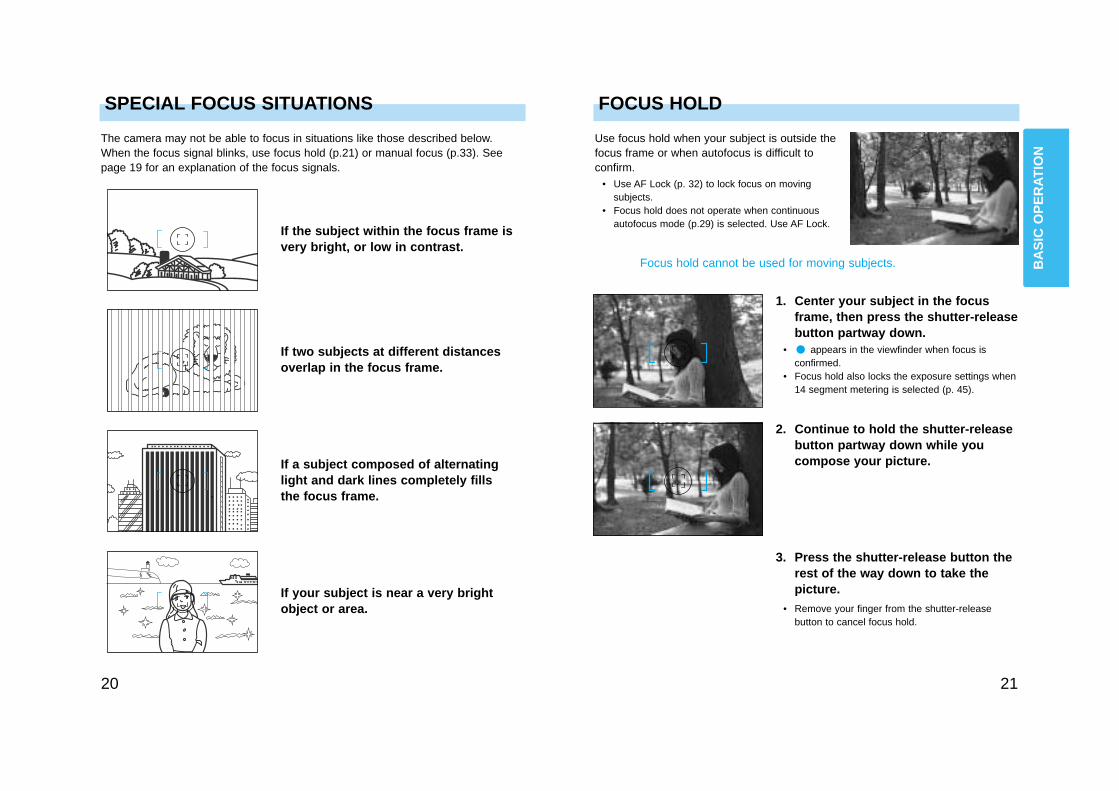
SPECIAL FOCUS SITUATIONS
The camera may not be able to focus in situations like those described below.When the focus signal blinks, use focus hold (p.21) or manual focus (p.33). Seepage 19 for an explanation of the focus signals.
If the subject within the focus frame isvery bright, or low in contrast.
If two subjects at different distancesoverlap in the focus frame.
If a subject composed of alternatinglight and dark lines completely fillsthe focus frame.
If your subject is near a very brightobject or area.
Use focus hold when your subject is outside thefocus frame or when autofocus is difficult toconfirm.
• Use AF Lock (p. 32) to lock focus on movingsubjects.
• Focus hold does not operate when continuousautofocus mode (p.29) is selected. Use AF Lock.
FOCUS HOLD
Focus hold cannot be used for moving subjects.
1. Center your subject in the focusframe, then press the shutter-releasebutton partway down.
• appears in the viewfinder when focus isconfirmed.
• Focus hold also locks the exposure settings when14 segment metering is selected (p. 45).
2. Continue to hold the shutter-releasebutton partway down while youcompose your picture.
3. Press the shutter-release button therest of the way down to take thepicture.
• Remove your finger from the shutter-releasebutton to cancel focus hold.
BA
SIC
OP
ER
AT
ION
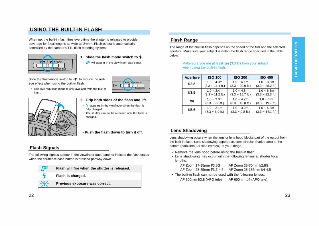
Slide the flash-mode switch to to reduce the red-eye effect when using the built-in flash.
• Red-eye reduction mode is only available with the built-inflash.
2322
USING THE BUILT-IN FLASH
When up, the built-in flash fires every time the shutter is released to providecoverage for focal lengths as wide as 24mm. Flash output is automaticallycontrolled by the camera’s TTL flash metering system.
2. Grip both sides of the flash and lift.• appears in the viewfinder when the flash is
fully charged.• The shutter can not be released until the flash is
charged.
1. Slide the flash mode switch to .• will appear in the viewfinder data panel.
- Push the flash down to turn it off.
The following signals appear in the viewfinder data panel to indicate the flash statuswhen the shutter-release button is pressed partway down.
Flash Signals
The range of the built-in flash depends on the speed of the film and the selectedaperture. Make sure your subject is within the flash range specified in the tablebelow.
Flash Range
Make sure you are at least 1m (3.3 ft.) from your subjectwhen using the built-in flash.
Aperture ISO 100 ISO 200 ISO 400
f/2.8
f/3.5
f/4
f/5.6
1.0 ~ 4.3m 1.0 ~ 6.1m 1.0 ~ 8.6m(3.3 ~ 14.1 ft.) (3.3 ~ 20.0 ft.) (3.3 ~ 28.2 ft.)
1.0 ~ 3.4m 1.0 ~ 4.8m 1.0 ~ 6.8m(3.3 ~ 11.2 ft.) (3.3 ~ 15.7 ft.) (3.3 ~ 22.3 ft.)
1.0 ~ 3.0m 1.0 ~ 4.2m 1.0 ~ 6.m(3.3 ~ 9.8 ft.) (3.3 ~ 13.8 ft.) (3.3 ~ 19.7 ft.)
1.0 ~ 2.1m 1.0 ~ 3.0m 1.0 ~ 4.3m(3.3 ~ 6.9 ft.) (3.3 ~ 9.8 ft.) (3.3 ~ 14.1 ft.)
Lens shadowing occurs when the lens or lens hood blocks part of the output fromthe built-in flash. Lens shadowing appears as semi-circular shaded area at thebottom (horizontal) or side (vertical) of your image.
Lens Shadowing
• Remove the lens hood before using the built-in flash.• Lens shadowing may occur with the following lenses at shorter focal
lengths.AF Zoom 17-35mm f/3.5G AF Zoom 28-70mm f/2.8GAF Zoom 28-85mm f/3.5-4.5 AF Zoom 28-135mm f/4-4.5
• The built-in flash can not be used with the following lenses:AF 300mm f/2.8 (APO tele) AF 600mm f/4 (APO tele)
Flash will fire when the shutter is released.
Flash is charged.
Previous exposure was correct.
BA
SIC
OP
ER
AT
ION
24
REWINDING THE FILM
1. Wait until the film is completely rewound.• will appear and will blink in the data panel.
Automatic RewindThe film is automatically rewound after the last frame is exposed (or 36 exposures).When the film is completely rewound, the motor will stop and will blink in thedata panel indicating it is safe to open the back of the camera.
3. Close the back cover.
2. Open the back cover and remove the film.
Manual RewindUse manual rewind to rewind the film before the current roll is finished.
1. Open the control panel door, thenpress the manual-rewind button.
DETAILEDOPERATION
2. Follow steps 1-3 from AutomaticRewind.
Automatic (1) or manually initiated (2) rewind (p.92).
Custom Function Notes
Rewind the leader into the cartridge (1)or leave the leader out (2) (p.92).
Fast or slow/silent rewind (p.97).
DE
TAIL
ED
OP
ER
ATI
ON
Predictive Focus Control determines thesubject’s speed, position, and accelerationchanges from the focus sensor data, then setsthe best focus at the predicted point ofexposure.Predictive focus control is always active in theAutomatic and Continuous autofocus modes.
27
FOCUS - Predictive Focus Control
FOCUSWith the ability to track acceleration in allthree dimensions, Predictive Focus Controlmakes it possible for the camera to calculatewhere your subject will be when the shutteropens.
FO
CU
S
FOCUS — Autofocus Modes
2928
Continuous Autofocus (C)Use Continuous Autofocus when shooting sporting events or when you knowthe subject will be in constant motion.
Center your subject in the focus frame,then press the shutter-release buttonpartway down to activate autofocus.The camera continues to focus as longas the shutter-release button ispressed partway down.• The AF Illuminator (p.34) does not operate in
Continuous Autofocus mode.• The focus area is not displayed unless the AF
button is pressed.
Single Shot Autofocus (S)Use Single-shot AF when photographing non-moving subjects or to lock focuson subjects outside the focus area.
Center your subject in the focus frame,then press the shutter-release buttonpartway down to activate autofocus.Once confirmed, focus remains lockeduntil pressure is removed from theshutter-release button or the shutter isreleased.
Selecting the Autofocus Mode
Automatic Autofocus (A)Designed to work well in almost any situation, Automatic Autofocus is especiallysuited to moving subjects that stop suddenly.
1. Set the focus mode switch to AF.
Center your subject in the focus frame,then press the shutter-release buttonpartway down to activate autofocus.The camera will continue focusingwhile the subject is moving, then lockfocus when the subject is still.
2. Turn the AF mode dial to the desiredmode.
FO
CU
S
The selected focus area momentarilyappears in the viewfinder frame when theshutter release button is pressed partwaydown.
• The focus area LEDs do not appear whencontinuous autofocus (p.29) is selected.
The camera determines which sensor is focusing onyour subject and sets the focus accordingly.
FOCUS — Focus Area
3130
Select a local focus area for greater control over the focus location in the autofocusmode.
• Only the center focus area can be selected when the RF 500mm or the AF Power Zoom35-80mm is mounted.
Local Focus Area
1. Press the AF button and turn thefront control dial to select thedesired local focus area.
• The local focus area is displayed in the focusframe and data panels.
2. Release the AF button when thedesired local focus area appears.
• The focus-area indicator displays the currentlyselected focus area.
The camera’s standard focus mode, wide focusarea uses the camera’s three focus sensors toautomatically focus on your subject. Wide focusarea’s greater framing flexibility makes it easierfor the camera to focus on moving subjects.
• appears in the viewfinder data panel whenwide focus area is selected.
Wide Focus Area
Wide / Local Focus Area (1) or Spot Focus (2) when the AF buttonis pressed (p.96).
Custom Function Notes
FO
CU
S
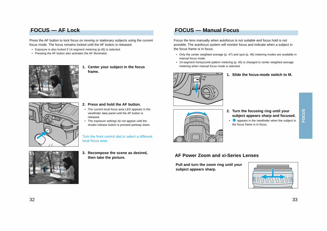
FOCUS — Manual FocusFOCUS — AF Lock
3332
Pull and turn the zoom ring until yoursubject appears sharp.
Focus the lens manually when autofocus is not suitable and focus hold is notpossible. The autofocus system will monitor focus and indicate when a subject inthe focus frame is in focus.
• Only the center weighted average (p. 47) and spot (p. 46) metering modes are available inmanual focus mode.
• 14-segment honeycomb pattern metering (p. 45) is changed to center weighted averagemetering when manual focus mode is selected.
1. Slide the focus-mode switch to M.
2. Turn the focusing ring until yoursubject appears sharp and focused.
• appears in the viewfinder when the subject inthe focus frame is in focus.
AF Power Zoom and xi-Series Lenses
Press the AF button to lock focus on moving or stationary subjects using the currentfocus mode. The focus remains locked until the AF button is released.
• Exposure is also locked if 14-segment metering (p.45) is selected.• Pressing the AF button also activates the AF illuminator.
1. Center your subject in the focusframe.
2. Press and hold the AF button.• The current local focus area LED appears in the
viewfinder data panel until the AF button isreleased.
• The exposure settings do not appear until theshutter-release button is pressed partway down.
3. Recompose the scene as desired,then take the picture.
Turn the front control dial to select a differentlocal focus area.
FO
CU
S
FOCUS — AF Illuminator
34
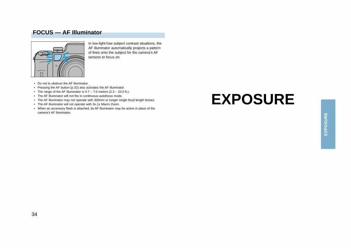
In low-light / low subject contrast situations, theAF illuminator automatically projects a patternof lines onto the subject for the camera’s AFsensors to focus on.
• Do not to obstruct the AF illuminator.• Pressing the AF button (p.32) also activates the AF illuminator.• The range of the AF Illuminator is 0.7 – 7.0 meters (2.3 – 23.0 ft.).• The AF illuminator will not fire in continuous autofocus mode.• The AF illuminator may not operate with 300mm or longer single focal length lenses.• The AF illuminator will not operate with 3x-1x Macro Zoom.• When an accessory flash is attached, its AF illuminator may be active in place of the
camera’s AF illuminator.
EXPOSURE
EX
PO
SU
RE
37
EXPOSURE — A-Mode
36
EXPOSURE — P-Mode
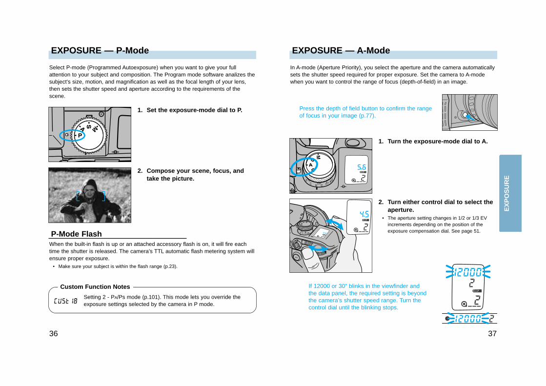
Select P-mode (Programmed Autoexposure) when you want to give your fullattention to your subject and composition. The Program mode software analizes thesubject’s size, motion, and magnification as well as the focal length of your lens,then sets the shutter speed and aperture according to the requirements of thescene.
1. Set the exposure-mode dial to P.
2. Compose your scene, focus, andtake the picture.
P-Mode FlashWhen the built-in flash is up or an attached accessory flash is on, it will fire eachtime the shutter is released. The camera’s TTL automatic flash metering system willensure proper exposure.
• Make sure your subject is within the flash range (p.23).
Press the depth of field button to confirm the rangeof focus in your image (p.77).
If 12000 or 30” blinks in the viewfinder andthe data panel, the required setting is beyondthe camera’s shutter speed range. Turn thecontrol dial until the blinking stops.
In A-mode (Aperture Priority), you select the aperture and the camera automaticallysets the shutter speed required for proper exposure. Set the camera to A-modewhen you want to control the range of focus (depth-of-field) in an image.
1. Turn the exposure-mode dial to A.
2. Turn either control dial to select theaperture.
• The aperture setting changes in 1/2 or 1/3 EVincrements depending on the position of theexposure compensation dial. See page 51.
Setting 2 - PA/Ps mode (p.101). This mode lets you override theexposure settings selected by the camera in P mode.
Custom Function Notes
EX
PO
SU
RE
If the aperture display in the viewfinder andthe data panel blinks, the required setting isoutside the aperture range of the lens. Turnthe control dial until the blinking stops.
EXPOSURE — S-ModeEXPOSURE — A-Mode
3938
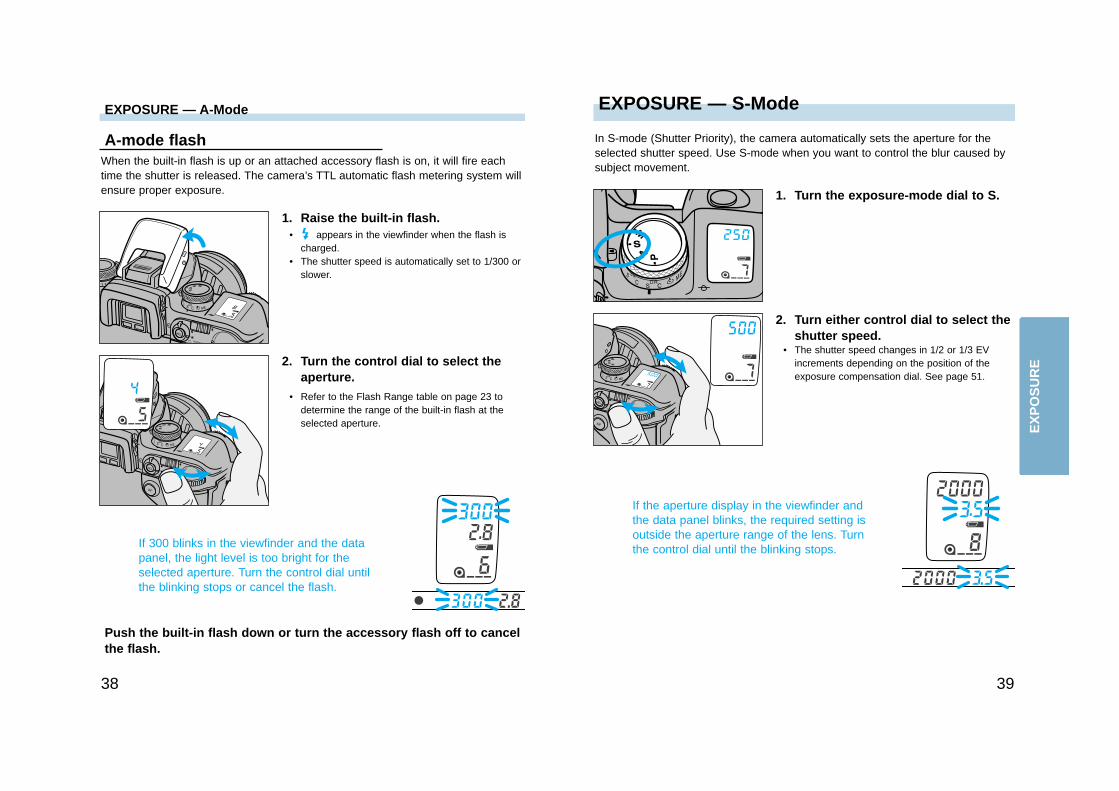
A-mode flashWhen the built-in flash is up or an attached accessory flash is on, it will fire eachtime the shutter is released. The camera’s TTL automatic flash metering system willensure proper exposure.
1. Raise the built-in flash.• appears in the viewfinder when the flash is
charged.• The shutter speed is automatically set to 1/300 or
slower.
2. Turn the control dial to select theaperture.
• Refer to the Flash Range table on page 23 todetermine the range of the built-in flash at theselected aperture.
If 300 blinks in the viewfinder and the datapanel, the light level is too bright for theselected aperture. Turn the control dial untilthe blinking stops or cancel the flash.
Push the built-in flash down or turn the accessory flash off to cancelthe flash.
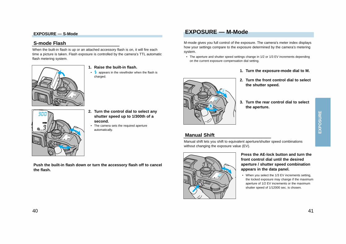
In S-mode (Shutter Priority), the camera automatically sets the aperture for theselected shutter speed. Use S-mode when you want to control the blur caused bysubject movement.
1. Turn the exposure-mode dial to S.
2. Turn either control dial to select theshutter speed.
• The shutter speed changes in 1/2 or 1/3 EVincrements depending on the position of theexposure compensation dial. See page 51.
EX
PO
SU
RE
EXPOSURE — M-ModeEXPOSURE — S-Mode
4140
S-mode FlashWhen the built-in flash is up or an attached accessory flash is on, it will fire eachtime a picture is taken. Flash exposure is controlled by the camera’s TTL automaticflash metering system.
1. Raise the built-in flash.• appears in the viewfinder when the flash is
charged.
2. Turn the control dial to select anyshutter speed up to 1/300th of asecond.
• The camera sets the required apertureautomatically.
Push the built-in flash down or turn the accessory flash off to cancelthe flash.
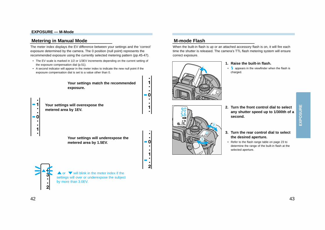
M-mode gives you full control of the exposure. The camera’s meter index displayshow your settings compare to the exposure determined by the camera’s meteringsystem.
• The aperture and shutter speed settings change in 1/2 or 1/3 EV increments dependingon the current exposure compensation dial setting.
1. Turn the exposure-mode dial to M.
2. Turn the front control dial to selectthe shutter speed.
Manual ShiftManual shift lets you shift to equivalent aperture/shutter speed combinationswithout changing the exposure value (EV).
Press the AE-lock button and turn thefront control dial until the desiredaperture / shutter speed combinationappears in the data panel.• When you select the 1/3 EV increments setting,
the locked exposure may change if the maximumaperture of 1/2 EV increments or the maximumshutter speed of 1/12000 sec. is chosen.
3. Turn the rear control dial to selectthe aperture.
EX
PO
SU
RE
4342
Metering in Manual ModeThe meter index displays the EV difference between your settings and the ‘correct’exposure determined by the camera. The 0 position (null point) represents therecommended exposure using the currently selected metering pattern (pp.45-47).
• The EV scale is marked in 1/2 or 1/3EV increments depending on the current setting ofthe exposure compensation dial (p.51).
• A second indicator will appear in the meter index to indicate the new null point if theexposure compensation dial is set to a value other than 0.
M-mode FlashWhen the built-in flash is up or an attached accessory flash is on, it will fire eachtime the shutter is released. The camera’s TTL flash metering system will ensurecorrect exposure.
1. Raise the built-in flash.• appears in the viewfinder when the flash is
charged.
2. Turn the front control dial to selectany shutter speed up to 1/300th of asecond.
3. Turn the rear control dial to selectthe desired aperture.
• Refer to the flash range table on page 23 todetermine the range of the built-in flash at theselected aperture.
Your settings match the recommendedexposure.
Your settings will overexpose themetered area by 1EV.
Your settings will underexpose themetered area by 1.5EV.
or will blink in the meter index if thesettings will over or underexpose the subjectby more than 3.0EV.
EXPOSURE — M-Mode
EX
PO
SU
RE
METERING — Selectable Metering
45
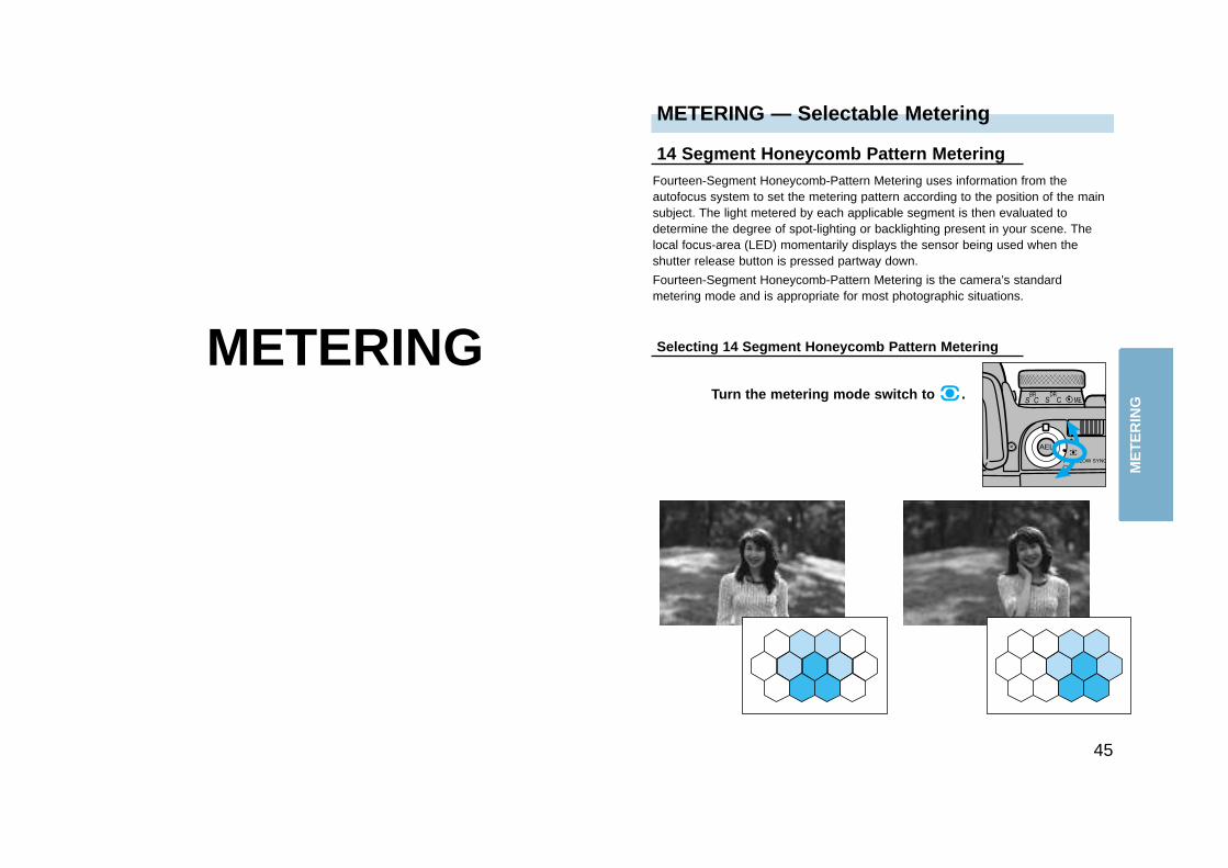
14 Segment Honeycomb Pattern MeteringFourteen-Segment Honeycomb-Pattern Metering uses information from theautofocus system to set the metering pattern according to the position of the mainsubject. The light metered by each applicable segment is then evaluated todetermine the degree of spot-lighting or backlighting present in your scene. Thelocal focus-area (LED) momentarily displays the sensor being used when theshutter release button is pressed partway down.
Fourteen-Segment Honeycomb-Pattern Metering is the camera’s standardmetering mode and is appropriate for most photographic situations.
METERINGTurn the metering mode switch to .
Selecting 14 Segment Honeycomb Pattern Metering
ME
TE
RIN
G
4746
METERING — Selectable Metering
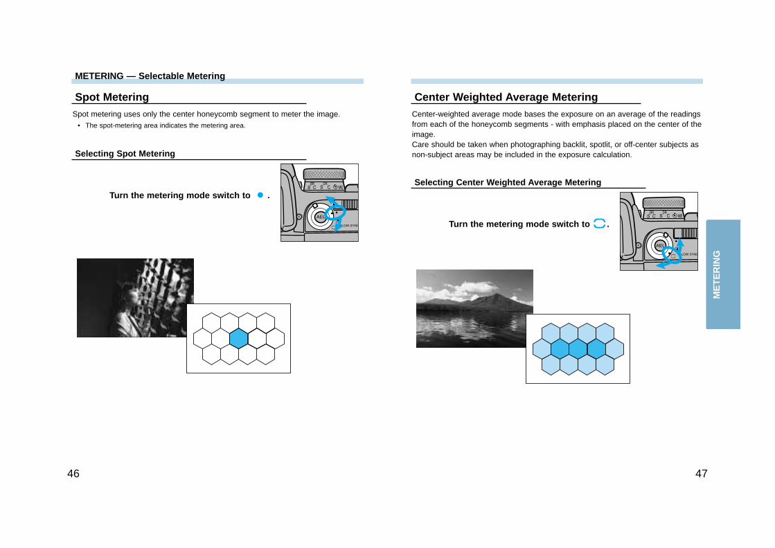
Spot MeteringSpot metering uses only the center honeycomb segment to meter the image.
• The spot-metering area indicates the metering area.
Turn the metering mode switch to .
Selecting Spot Metering
Center Weighted Average MeteringCenter-weighted average mode bases the exposure on an average of the readingsfrom each of the honeycomb segments - with emphasis placed on the center of theimage.Care should be taken when photographing backlit, spotlit, or off-center subjects asnon-subject areas may be included in the exposure calculation.
Turn the metering mode switch to .
Selecting Center Weighted Average Metering
ME
TE
RIN
G
4948
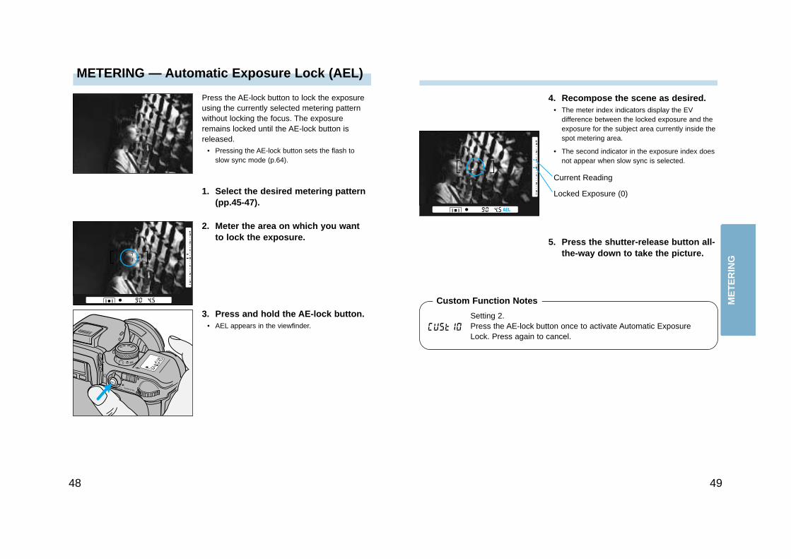
METERING — Automatic Exposure Lock (AEL)
Press the AE-lock button to lock the exposureusing the currently selected metering patternwithout locking the focus. The exposureremains locked until the AE-lock button isreleased.
• Pressing the AE-lock button sets the flash toslow sync mode (p.64).
1. Select the desired metering pattern(pp.45-47).
2. Meter the area on which you wantto lock the exposure.
3. Press and hold the AE-lock button.• AEL appears in the viewfinder.
4. Recompose the scene as desired.• The meter index indicators display the EV
difference between the locked exposure and theexposure for the subject area currently inside thespot metering area.
• The second indicator in the exposure index doesnot appear when slow sync is selected.
5. Press the shutter-release button all-the-way down to take the picture.
Locked Exposure (0)
Current Reading
Setting 2.Press the AE-lock button once to activate Automatic ExposureLock. Press again to cancel.
Custom Function Notes ME
TE
RIN
G
Select setting 2 to view the exposure compensation value in thedata panel when the exposure compensation dial is set to a valueother than 0.
More exposure is recommended when the scene isprimarily white tones.
Less exposure is recommended when the scene iscomposed of darker tones or shadows.
5150
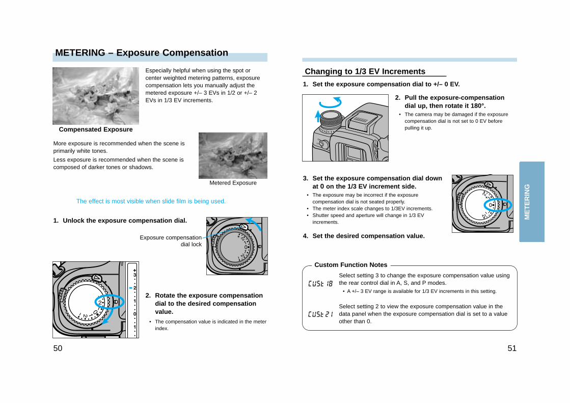
METERING – Exposure Compensation
1. Set the exposure compensation dial to +/– 0 EV.
Changing to 1/3 EV Increments
2. Pull the exposure-compensationdial up, then rotate it 180°.
• The camera may be damaged if the exposurecompensation dial is not set to 0 EV beforepulling it up.
3. Set the exposure compensation dial downat 0 on the 1/3 EV increment side.
• The exposure may be incorrect if the exposurecompensation dial is not seated properly.
• The meter index scale changes to 1/3EV increments.• Shutter speed and aperture will change in 1/3 EV
increments.
4. Set the desired compensation value.
1. Unlock the exposure compensation dial.
Especially helpful when using the spot orcenter weighted metering patterns, exposurecompensation lets you manually adjust themetered exposure +/– 3 EVs in 1/2 or +/– 2EVs in 1/3 EV increments.
Compensated Exposure
Metered Exposure
2. Rotate the exposure compensationdial to the desired compensationvalue.
• The compensation value is indicated in the meterindex.
The effect is most visible when slide film is being used.
Exposure compensationdial lock
Select setting 3 to change the exposure compensation value usingthe rear control dial in A, S, and P modes.
• A +/– 3 EV range is available for 1/3 EV increments in this setting.
Custom Function Notes
ME
TE
RIN
G
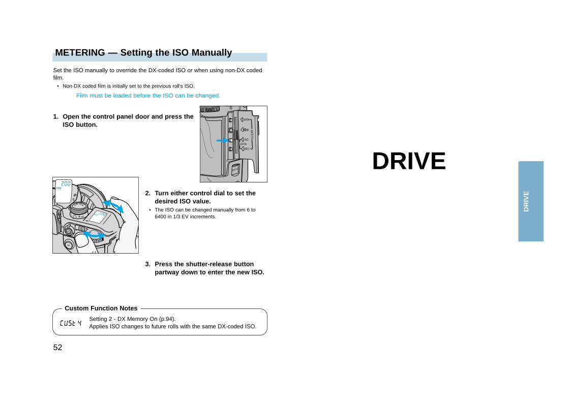
METERING — Setting the ISO Manually
52
Set the ISO manually to override the DX-coded ISO or when using non-DX codedfilm.
• Non-DX coded film is initially set to the previous roll’s ISO.
Film must be loaded before the ISO can be changed.
1. Open the control panel door and press theISO button.
2. Turn either control dial to set thedesired ISO value.
• The ISO can be changed manually from 6 to6400 in 1/3 EV increments.
3. Press the shutter-release buttonpartway down to enter the new ISO.
DRIVE
Setting 2 - DX Memory On (p.94).Applies ISO changes to future rolls with the same DX-coded ISO.
Custom Function Notes
DR
IVE
5554
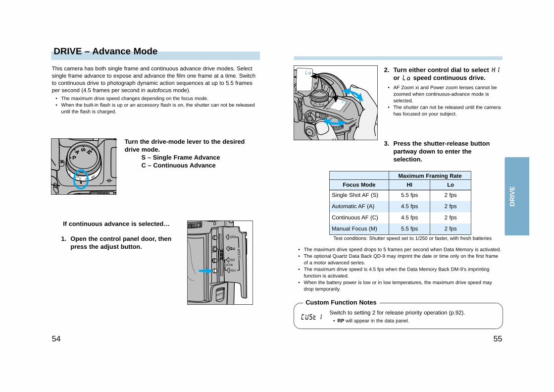
DRIVE – Advance Mode
This camera has both single frame and continuous advance drive modes. Selectsingle frame advance to expose and advance the film one frame at a time. Switchto continuous drive to photograph dynamic action sequences at up to 5.5 framesper second (4.5 frames per second in autofocus mode).
• The maximum drive speed changes depending on the focus mode.• When the built-in flash is up or an accessory flash is on, the shutter can not be released
until the flash is charged.
Turn the drive-mode lever to the desireddrive mode.
S – Single Frame AdvanceC – Continuous Advance
If continuous advance is selected…
1. Open the control panel door, thenpress the adjust button.
2. Turn either control dial to select or speed continuous drive.
• AF Zoom xi and Power zoom lenses cannot bezoomed when continuous-advance mode isselected.
• The shutter can not be released until the camerahas focused on your subject.
• The maximum drive speed drops to 5 frames per second when Data Memory is activated.• The optional Quartz Data Back QD-9 may imprint the date or time only on the first frame
of a motor advanced series.• The maximum drive speed is 4.5 fps when the Data Memory Back DM-9’s imprinting
function is activated.• When the battery power is low or in low temperatures, the maximum drive speed may
drop temporarily.
Focus Mode
Single Shot AF (S)
Automatic AF (A)
Continuous AF (C)
Manual Focus (M)
Maximum Framing Rate
HI Lo
5.5 fps 2 fps
4.5 fps 2 fps
4.5 fps 2 fps
5.5 fps 2 fps
3. Press the shutter-release buttonpartway down to enter theselection.
Switch to setting 2 for release priority operation (p.92).• RP will appear in the data panel.
Custom Function Notes
DR
IVE
Test conditions: Shutter speed set to 1/250 or faster, with fresh batteries
DRIVE – Self-Timer
5756
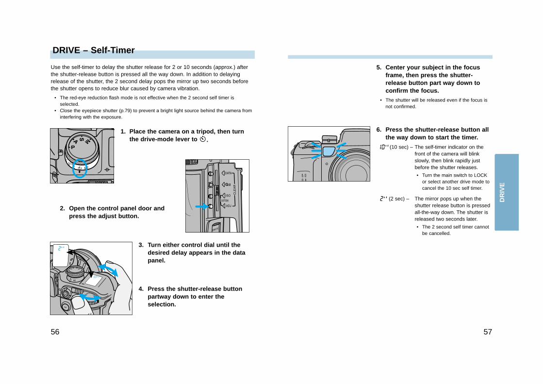
5. Center your subject in the focusframe, then press the shutter-release button part way down toconfirm the focus.
• The shutter will be released even if the focus isnot confirmed.
6. Press the shutter-release button allthe way down to start the timer.
(10 sec) – The self-timer indicator on thefront of the camera will blinkslowly, then blink rapidly justbefore the shutter releases.
• Turn the main switch to LOCKor select another drive mode tocancel the 10 sec self timer.
(2 sec) – The mirror pops up when theshutter release button is pressedall-the-way down. The shutter isreleased two seconds later.
• The 2 second self timer cannotbe cancelled.
2. Open the control panel door andpress the adjust button.
1. Place the camera on a tripod, then turnthe drive-mode lever to .
Use the self-timer to delay the shutter release for 2 or 10 seconds (approx.) afterthe shutter-release button is pressed all the way down. In addition to delayingrelease of the shutter, the 2 second delay pops the mirror up two seconds beforethe shutter opens to reduce blur caused by camera vibration.
• The red-eye reduction flash mode is not effective when the 2 second self timer isselected.
• Close the eyepiece shutter (p.79) to prevent a bright light source behind the camera frominterfering with the exposure.
3. Turn either control dial until thedesired delay appears in the datapanel.
4. Press the shutter-release buttonpartway down to enter theselection.
DR
IVE
DRIVE – Exposure Bracketing
5958
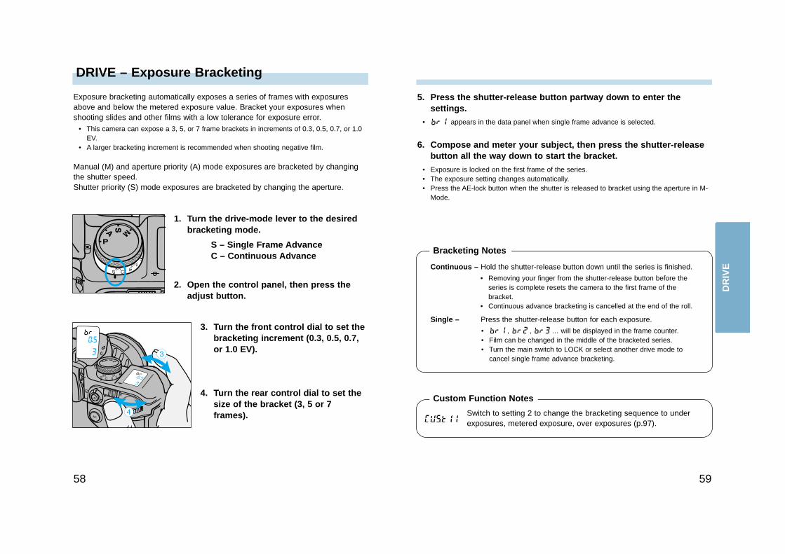
3. Turn the front control dial to set thebracketing increment (0.3, 0.5, 0.7, or 1.0 EV).
6. Compose and meter your subject, then press the shutter-releasebutton all the way down to start the bracket.
• Exposure is locked on the first frame of the series.• The exposure setting changes automatically.• Press the AE-lock button when the shutter is released to bracket using the aperture in M-
Mode.
1. Turn the drive-mode lever to the desiredbracketing mode.
S – Single Frame AdvanceC – Continuous Advance
Exposure bracketing automatically exposes a series of frames with exposuresabove and below the metered exposure value. Bracket your exposures whenshooting slides and other films with a low tolerance for exposure error.
• This camera can expose a 3, 5, or 7 frame brackets in increments of 0.3, 0.5, 0.7, or 1.0EV.
• A larger bracketing increment is recommended when shooting negative film.
Manual (M) and aperture priority (A) mode exposures are bracketed by changingthe shutter speed.Shutter priority (S) mode exposures are bracketed by changing the aperture.
2. Open the control panel, then press theadjust button.
4. Turn the rear control dial to set thesize of the bracket (3, 5 or 7frames).
Continuous – Hold the shutter-release button down until the series is finished.
• Removing your finger from the shutter-release button before theseries is complete resets the camera to the first frame of thebracket.
• Continuous advance bracketing is cancelled at the end of the roll.
Single – Press the shutter-release button for each exposure.
• , , … will be displayed in the frame counter.• Film can be changed in the middle of the bracketed series.• Turn the main switch to LOCK or select another drive mode to
cancel single frame advance bracketing.
5. Press the shutter-release button partway down to enter thesettings.
• appears in the data panel when single frame advance is selected.
Switch to setting 2 to change the bracketing sequence to underexposures, metered exposure, over exposures (p.97).
Custom Function Notes
Bracketing Notes
DR
IVE
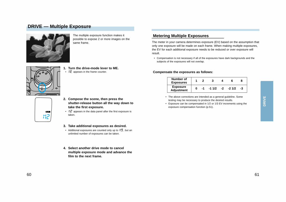
DRIVE — Multiple Exposure
6160
The meter in your camera determines exposure (EV) based on the assumption thatonly one exposure will be made on each frame. When making multiple exposures,the EV for each additional exposure needs to be reduced or over exposure willresult.
• Compensation is not necessary if all of the exposures have dark backgrounds and thesubjects of the exposures will not overlap.
Metering Multiple Exposures
Compensate the exposures as follows:
Number ofExposuresExposure
Adjustment
• The above corrections are intended as a general guideline. Sometesting may be necessary to produce the desired results.
• Exposure can be compensated in 1/2 or 1/3 EV increments using theexposure compensation function (p.51).
2. Compose the scene, then press theshutter-release button all the way down totake the first exposure.
• appears in the data panel after the first exposure istaken.
1. Turn the drive-mode lever to ME.• appears in the frame counter.
The multiple exposure function makes itpossible to expose 2 or more images on thesame frame.
3. Take additional exposures as desired.• Additional exposures are counted only up to , but an
unlimited number of exposures can be taken.
4. Select another drive mode to cancelmultiple exposure mode and advance thefilm to the next frame.
1 2 3 4 6 8
0 -1 -1 1/2 -2 -2 1/2 -3
DR
IVE
63
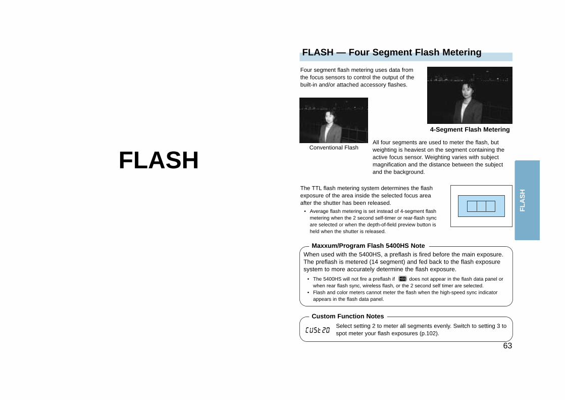
FLASH — Four Segment Flash Metering
FLASH
Four segment flash metering uses data fromthe focus sensors to control the output of thebuilt-in and/or attached accessory flashes.
The TTL flash metering system determines the flashexposure of the area inside the selected focus areaafter the shutter has been released.
• Average flash metering is set instead of 4-segment flashmetering when the 2 second self-timer or rear-flash syncare selected or when the depth-of-field preview button isheld when the shutter is released.
4-Segment Flash Metering
Conventional Flash
Select setting 2 to meter all segments evenly. Switch to setting 3 tospot meter your flash exposures (p.102).
Custom Function Notes
Maxxum/Program Flash 5400HS NoteWhen used with the 5400HS, a preflash is fired before the main exposure.The preflash is metered (14 segment) and fed back to the flash exposuresystem to more accurately determine the flash exposure.
• The 5400HS will not fire a preflash if does not appear in the flash data panel orwhen rear flash sync, wireless flash, or the 2 second self timer are selected.
• Flash and color meters cannot meter the flash when the high-speed sync indicatorappears in the flash data panel.
All four segments are used to meter the flash, butweighting is heaviest on the segment containing theactive focus sensor. Weighting varies with subjectmagnification and the distance between the subjectand the background.
FL
AS
H
FLASH – Rear-Flash SyncFLASH – Slow Sync
6564
In P and A-modes, slow-shutter sync sets aslower shutter speed to increase thebackground or ambient exposure in a flashpicture. Flash output is automaticallydecreased to maintain correct subjectexposure.
Slow-shutter Sync
Conventional Flash
2. While pressing the AE-lock button,press the shutter-release button allthe way down to take the picture.
• AEL and the locked exposure will be displayed inthe viewfinder.
• The shutter speed may not be reduced if thebackground is bright or a large aperture is set (A-mode).
• Use a tripod if the shutter speed becomes tooslow to allow sharp, hand-held pictures.
Slow sync flash exposures can appearunnatural because the motion blur precedesthe subject in the final image. Use rear-flashsync to create more natural looking slowshutter speed flash exposures that leave a blurof motion behind the subject.
Rear Flash Sync
Conventional Flash
1. Slide the flash-mode switch toREAR.
Rear-flash sync can be used with the built-inflash and accessory flashes attached to theaccessory shoe or PC terminal.
3. Set the shutter speed to 1/60 orslower.
• Flash synchronization returns to front sync(standard operation) when shutter speeds fasterthan 1/60 are selected.
• Refer to S-mode Flash (p.40) or M-mode Flash(p.43) to select the shutter speed.
1. Raise the built-in flash or turn theaccessory flash on.
2. Raise the built-in flash or turn theaccessory flash on.
Custom Function Notes
FL
AS
H
Setting 2 lets you press the AE-lock button once to activateautomatic exposure lock. Press again to cancel (p.96).
FLASH — Flash CompensationFLASH — High Speed Sync
6766
The maximum sync speed for this camera is1/300. However, with the 5400HS accessoryflash (sold separately) shutter speeds up to1/12000 can be used. High-speed sync (HSS)allows faster shutter speeds when fill flash isused on moving subjects outdoors.
HSS also lets you use large aperture/high shutter-speed combinations to separate your subject from thebackground by limiting the depth-of-field.
High-speed Sync
Conventional Fill Flash
Attach the 5400HS flash and set it to standard mode.• automatically appears in the viewfinder at shutter speeds faster than 1/300 sec when
the 5400HS is attached.
• Selecting HSS flash mode under fluorescent lighting may result in incorrect exposure.• Flash and color meters cannot meter the flash when high-speed sync is selected.• Pressing the depth-of-field button in HSS flash mode prevents release of the shutter.• HSS is not available in wireless/remote flash mode or when the 2 second self-timer has
been selected.• If you attach a filter whose stop’s increase is not 0 (i.e., ND), the proper exposure will not
be obtained. Press the flash’s HSS button to cancel the HSS.
Refer to the 5400HS instruction manual for details.
Use flash compensation to increase or decrease the output of the built-in or anattached accessory flash up to +/–3 EV in 1/2EV increments.
Flash compensation changes the flash exposure by the amount set relative to theambient exposure.
Rotate the flash-compensation dial tothe desired compensation value.• Flash compensation does not modify the output
of a flash connected to the PC terminal.• Flash compensation has no effect on the ambient
light exposure.
Flash compensation and exposure compensation can be usedtogether.
FL
AS
H
FLASH – Flash Bracketing
6968
Use flash bracketing to expose 3, 5, or 7 frame flash exposure brackets in 0.3, 0.5,0.7, or 1.0 EV increments. Exposures are bracketed by controlling the flash output.
• A larger bracketing increment is recommended when shooting negative film.
1. Raise the built-in flash or turn theaccessory flash on.
2. Turn the drive-mode lever to single frame(S) or continuous advance (C) bracketingmode.
• The shutter-release button must be pressed for eachexposure in both single and continuous advancebracketing modes.
3. Open the control panel, then press theadjust button.
7. Compose your subject.
8. When appears in the viewfinder, press the shutter-releasebutton all-the-way down to take the picture.
• Exposure is locked on the first frame of the series.
9. Repeat steps 7 and 8 until the series is complete.• The bracket number is indicated in the data panel.• Turn the main switch to LOCK, change the drive mode, push the built-in flash down, or
turn off the accessory flash to cancel the bracketed series.• Film can be changed in the middle of the bracketed series.
Flash Bracketing with PC Connected Flash Units
1. Set the camera to M-mode (p. 41).
2. Press the AE-lock button whilereleasing the shutter.
• The exposure will be bracketed by changing theaperture. The output of the flash will not change.
4. Turn the front control dial to set thebracketing increment. (0.3, 0.5, 0.7,or 1.0EV).
5. Turn the rear control dial to set thesize of the bracket (3, 5 or 7frames).
6. Press the shutter-release button partwaydown to enter the settings.
• appears in the data panel.
Switch to setting 2 to change the bracketing sequence to underexposures, metered exposure, over exposures (p.97).
Custom Function Notes
FL
AS
H
FLASH — Wireless/Remote Off-Camera
7170
Wireless/Remote Flash is available with theMinolta 5400HS, 5400xi, and 3500xi accessoryflashes. Wireless/Remote flash lets youexperience the creative control available withan accessory flash.
In Wireless/Remote flash mode, the off-cameraflash is triggered by a coded signal from thecamera’s built-in flash when you press theshutter-release button. When proper exposurehas been received, another signal cuts theaccessory flash off.
You can also achieve a 2:1 lighting ratioautomatically. When remote ratio flash isselected, the off-camera flash provides 2/3 ofthe full exposure while the built-in flashprovides the remaining 1/3.
• Flash and color meters can not be used to meterwireless/remote off-camera flash.
• The shutter speed will be set to 1/60 sec orslower.
• When using 5400HS or Wireless RemoteController as a controller instead of built-in flash,off-camera flash will not fire if you are pressingdepth-of-preview button.
Normal Flash
Wireless/Remote Flash
Wireless/Remote Ratio Flash
Setting Wireless/Remote Flash Mode
1. Attach the accessory flash to thecamera, then turn the camera andthe flash on.
2. Slide the flash-mode switch toWIRELESS.
3. Detach the accessory flash, thenraise the built-in flash. F
LA
SH
FLASH — Wireless/Remote Off-Camera
73
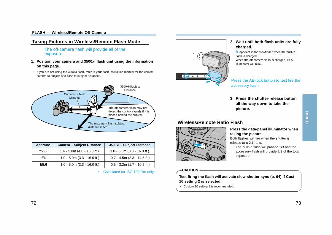
Taking Pictures in Wireless/Remote Flash Mode
The off-camera flash will provide all of theexposure.
1. Position your camera and 3500xi flash unit using the informationon this page.
• If you are not using the 3500xi flash, refer to your flash instruction manual for the correctcamera to subject and flash to subject distances.
• Calculated for ISO 100 film only.
Press the AE-lock button to test fire theaccessory flash.
3. Press the shutter-release buttonall the way down to take thepicture.
2. Wait until both flash units are fullycharged.
• appears in the viewfinder when the built-inflash is charged.
• When the off-camera flash is charged, its AFilluminator will blink.
Press the data-panel illuminator whentaking the picture.Both flashes will fire when the shutter isrelease at a 2:1 ratio.
• The built-in flash will provide 1/3 and theaccessory flash will provide 2/3 of the totalexposure.
Wireless/Remote Ratio Flash
Test firing the flash will activate slow-shutter sync (p. 64) if Cust10 setting 2 is selected.• Custom 10 setting 1 is recommended.
CAUTION
3500xi-SubjectDistance
Camera-SubjectDistance
The off-camera flash may notdetect the control signals if it isplaced behind the subject.
The maximum flash-subjectdistance is 5m.
Aperture Camera – Subject Distance 3500xi – Subject Distance
f/2.8 1.4 - 5.0m (4.6 - 16.0 ft.) 1.0 - 5.0m (3.3 - 16.0 ft.)
f/4 1.0 - 5.0m (3.3 - 16.0 ft.) 0.7 - 4.5m (2.3 - 14.5 ft.)
f/5.6 1.0 - 5.0m (3.3 - 16.0 ft.) 0.5 - 3.2m (1.7 - 10.5 ft.)
72
FL
AS
H

74
Cancelling Wireless/Remote Flash Mode
1. Attach the accessory flash to thecamera, then turn the camera andflash on.
2. Select another flash mode.
3. Detach the accessory flash.
ADDITIONALFEATURES
FLASH — Wireless/Remote Off-Camera
AD
DIT
ION
AL
FEAT
UR
ES
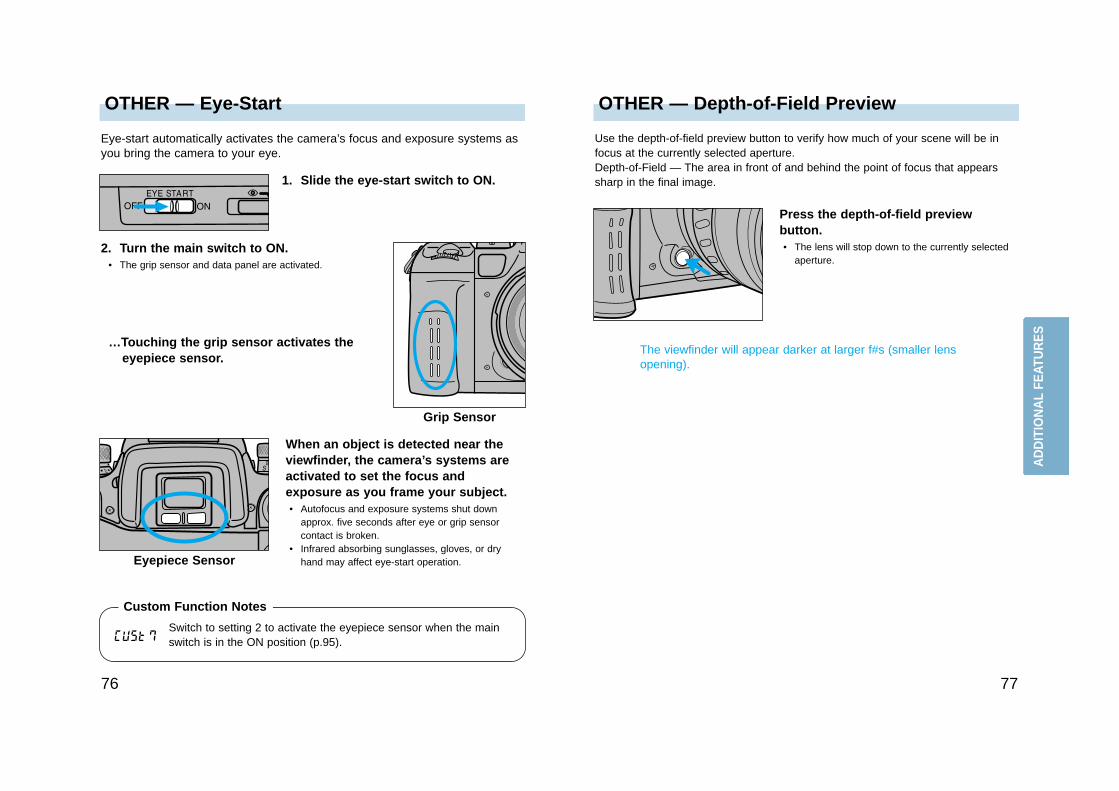
OTHER — Depth-of-Field PreviewOTHER — Eye-Start
7776
Use the depth-of-field preview button to verify how much of your scene will be infocus at the currently selected aperture.Depth-of-Field — The area in front of and behind the point of focus that appearssharp in the final image.
Press the depth-of-field previewbutton.• The lens will stop down to the currently selected
aperture.
The viewfinder will appear darker at larger f#s (smaller lensopening).
…Touching the grip sensor activates theeyepiece sensor.
2. Turn the main switch to ON.• The grip sensor and data panel are activated.
When an object is detected near theviewfinder, the camera’s systems areactivated to set the focus andexposure as you frame your subject.• Autofocus and exposure systems shut down
approx. five seconds after eye or grip sensorcontact is broken.
• Infrared absorbing sunglasses, gloves, or dryhand may affect eye-start operation.Eyepiece Sensor
Eye-start automatically activates the camera’s focus and exposure systems asyou bring the camera to your eye.
1. Slide the eye-start switch to ON.
Grip Sensor
Custom Function Notes
AD
DIT
ION
AL
FEAT
UR
ES
Switch to setting 2 to activate the eyepiece sensor when the mainswitch is in the ON position (p.95).
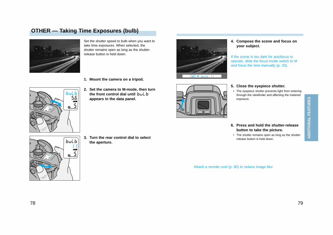
OTHER — Taking Time Exposures (bulb)
7978
Set the shutter speed to bulb when you want totake time exposures. When selected, theshutter remains open as long as the shutter-release button is held down.
1. Mount the camera on a tripod.
2. Set the camera to M-mode, then turnthe front control dial until appears in the data panel.
4. Compose the scene and focus onyour subject.
If the scene is too dark for autofocus tooperate, slide the focus-mode switch to Mand focus the lens manually (p. 33).
5. Close the eyepiece shutter.• The eyepiece shutter prevents light from entering
through the viewfinder and affecting the meteredexposure.
6. Press and hold the shutter-releasebutton to take the picture.
• The shutter remains open as long as the shutter-release button is held down.
Attach a remote cord (p. 80) to reduce image blur.
3. Turn the rear control dial to selectthe aperture.
AD
DIT
ION
AL
FEAT
UR
ES
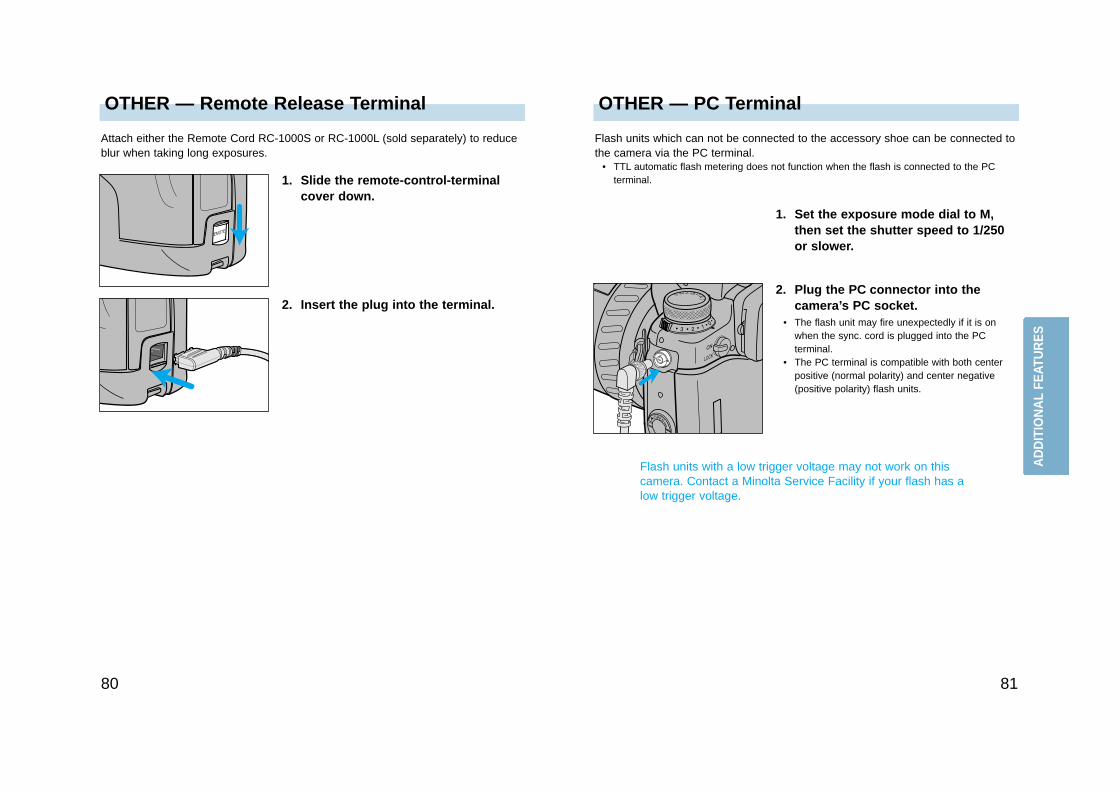
OTHER — PC TerminalOTHER — Remote Release Terminal
8180
Flash units which can not be connected to the accessory shoe can be connected tothe camera via the PC terminal.
• TTL automatic flash metering does not function when the flash is connected to the PCterminal.
1. Set the exposure mode dial to M,then set the shutter speed to 1/250or slower.
Flash units with a low trigger voltage may not work on thiscamera. Contact a Minolta Service Facility if your flash has alow trigger voltage.
2. Plug the PC connector into thecamera’s PC socket.
• The flash unit may fire unexpectedly if it is onwhen the sync. cord is plugged into the PCterminal.
• The PC terminal is compatible with both centerpositive (normal polarity) and center negative(positive polarity) flash units.
1. Slide the remote-control-terminalcover down.
Attach either the Remote Cord RC-1000S or RC-1000L (sold separately) to reduceblur when taking long exposures.
2. Insert the plug into the terminal.
AD
DIT
ION
AL
FEAT
UR
ES
82
OTHER — Data Panel Illuminator
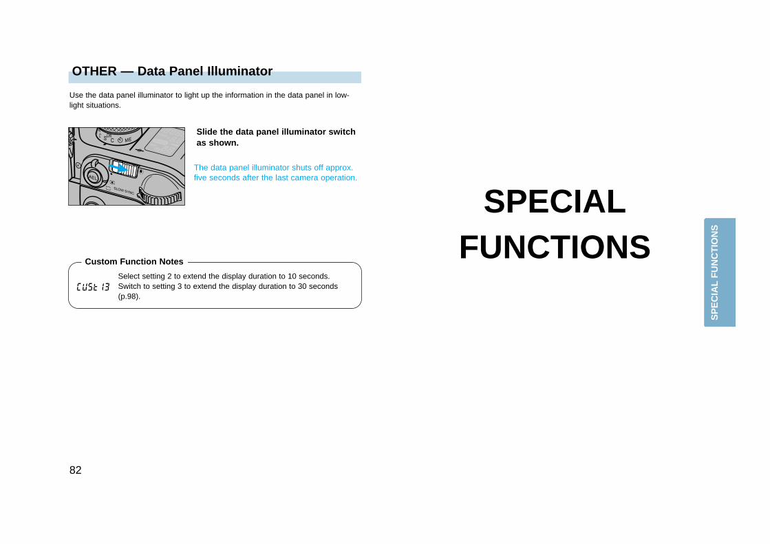
Use the data panel illuminator to light up the information in the data panel in low-light situations.
Slide the data panel illuminator switchas shown.
The data panel illuminator shuts off approx.five seconds after the last camera operation.
SPECIALFUNCTIONS
Select setting 2 to extend the display duration to 10 seconds.Switch to setting 3 to extend the display duration to 30 seconds(p.98).
Custom Function Notes
SP
EC
IAL
FU
NC
TIO
NS
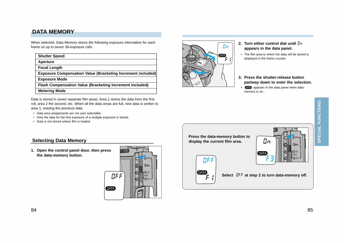
2. Turn either control dial until appears in the data panel.
• The film area to which the data will be stored isdisplayed in the frame counter.
DATA MEMORY
8584
Select at step 2 to turn data-memory off.
3. Press the shutter-release buttonpartway down to enter the selection.
• appears in the data panel when data-memory is on.
Press the data-memory button todisplay the current film area.
When selected, Data Memory stores the following exposure information for eachframe on up to seven 36-exposure rolls.
Data is stored in seven separate film areas. Area 1 stores the data from the firstroll, area 2 the second, etc. When all the data areas are full, new data is written toarea 1, erasing the previous data.
• Data area assignments are not user selectable.• Only the data for the first exposure of a multiple exposure is stored.• Data is not stored unless film is loaded.
Selecting Data Memory
1. Open the control panel door, then pressthe data-memory button.
Shutter Speed
Aperture
Focal Length
Exposure Compensation Value (Bracketing Increment included)
Exposure Mode
Flash Compensation Value (Bracketing Increment included)
Metering Mode
SP
EC
IAL
FU
NC
TIO
NS
2. Turn either control dial until and the desired data area appears inthe data panel.
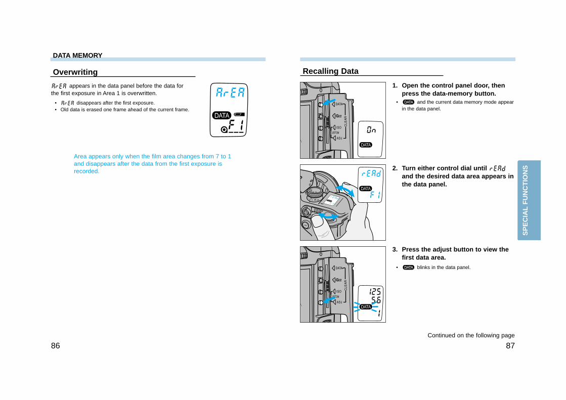
8786
Recalling Data
1. Open the control panel door, thenpress the data-memory button.
• and the current data memory mode appearin the data panel.
3. Press the adjust button to view thefirst data area.
• blinks in the data panel.
Continued on the following page
Overwriting
appears in the data panel before the data forthe first exposure in Area 1 is overwritten.
• disappears after the first exposure.• Old data is erased one frame ahead of the current frame.
Area appears only when the film area changes from 7 to 1and disappears after the data from the first exposure isrecorded.
DATA MEMORY
SP
EC
IAL
FU
NC
TIO
NS
8988
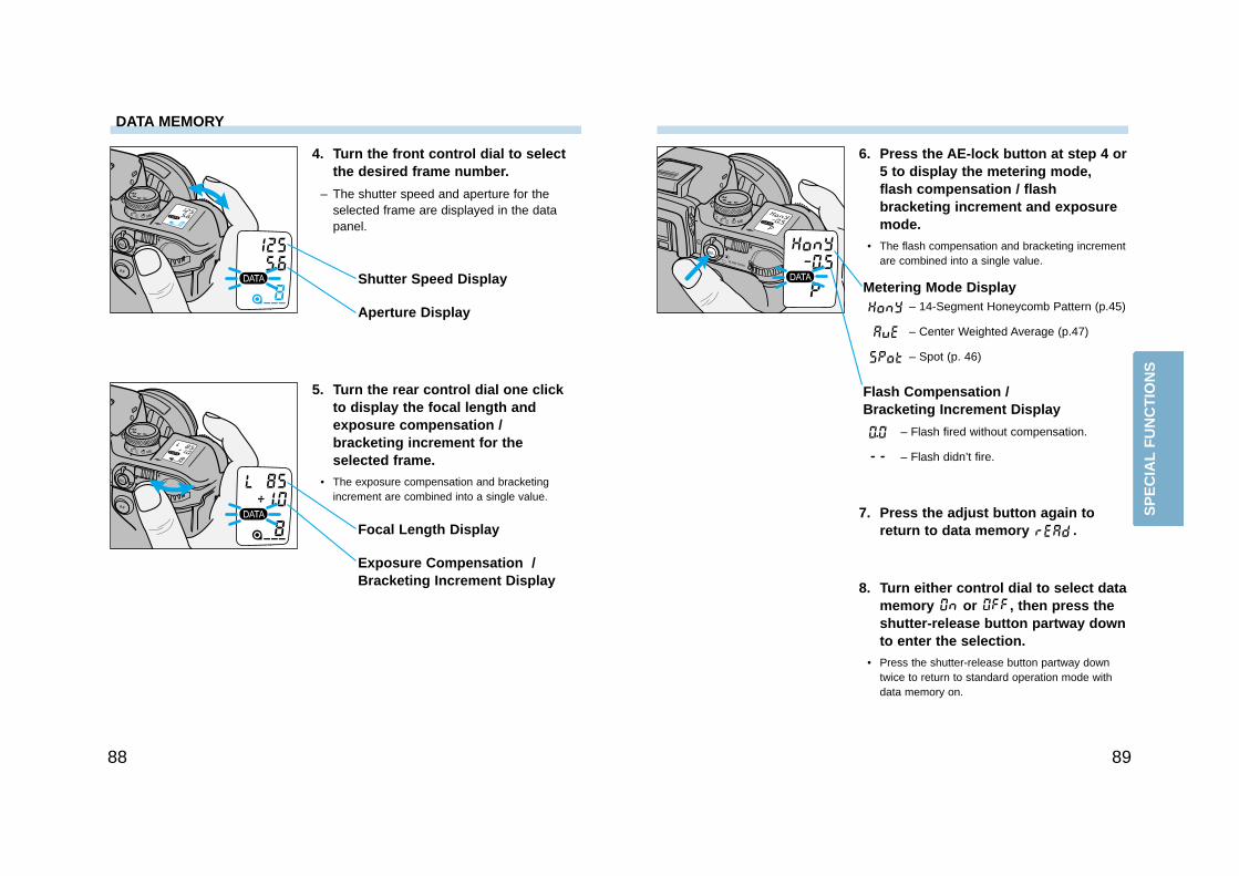
5. Turn the rear control dial one clickto display the focal length andexposure compensation /bracketing increment for theselected frame.
• The exposure compensation and bracketingincrement are combined into a single value.
Focal Length Display
Exposure Compensation /Bracketing Increment Display
4. Turn the front control dial to selectthe desired frame number.
– The shutter speed and aperture for theselected frame are displayed in the datapanel.
Shutter Speed Display
Aperture Display
DATA MEMORY
7. Press the adjust button again toreturn to data memory .
8. Turn either control dial to select datamemory or , then press theshutter-release button partway downto enter the selection.
• Press the shutter-release button partway downtwice to return to standard operation mode withdata memory on.
6. Press the AE-lock button at step 4 or5 to display the metering mode,flash compensation / flashbracketing increment and exposuremode.
• The flash compensation and bracketing incrementare combined into a single value.
Metering Mode Display
Flash Compensation / Bracketing Increment Display
– 14-Segment Honeycomb Pattern (p.45)
– Center Weighted Average (p.47)
– Spot (p. 46)
– Flash fired without compensation.
– Flash didn’t fire.
SP
EC
IAL
FU
NC
TIO
NS
9190
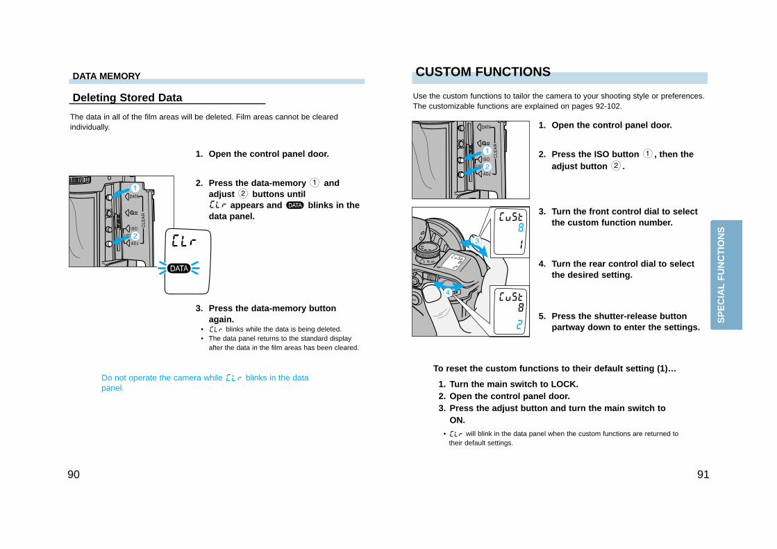
Deleting Stored Data
The data in all of the film areas will be deleted. Film areas cannot be clearedindividually.
2. Press the data-memory andadjust buttons until
appears and blinks in thedata panel.
1. Open the control panel door.
3. Press the data-memory buttonagain.
• blinks while the data is being deleted.• The data panel returns to the standard display
after the data in the film areas has been cleared.
Do not operate the camera while blinks in the datapanel.
DATA MEMORY
2. Press the ISO button , then theadjust button .
CUSTOM FUNCTIONS
1. Open the control panel door.
Use the custom functions to tailor the camera to your shooting style or preferences.The customizable functions are explained on pages 92-102.
3. Turn the front control dial to selectthe custom function number.
To reset the custom functions to their default setting (1)…
1. Turn the main switch to LOCK.2. Open the control panel door.3. Press the adjust button and turn the main switch to
ON.• will blink in the data panel when the custom functions are returned to
their default settings.
5. Press the shutter-release buttonpartway down to enter the settings.
4. Turn the rear control dial to selectthe desired setting.
SP
EC
IAL
FU
NC
TIO
NS
CUSTOM FUNCTIONS
9392
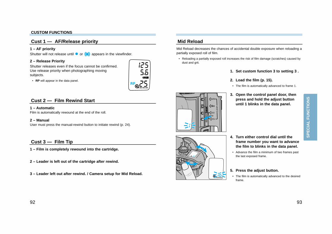
Mid ReloadMid Reload decreases the chances of accidental double exposure when reloading apartially exposed roll of film.
• Reloading a partially exposed roll increases the risk of film damage (scratches) caused bydust and grit.
1. Set custom function 3 to setting 3 .
2. Load the film (p. 15).• The film is automatically advanced to frame 1.
3. Open the control panel door, thenpress and hold the adjust buttonuntil 1 blinks in the data panel.
4. Turn either control dial until theframe number you want to advancethe film to blinks in the data panel.
• Advance the film a minimum of two frames pastthe last exposed frame.
5. Press the adjust button.• The film is automatically advanced to the desired
frame.
Cust 1 — AF/Release priority
1 – AF priorityShutter will not release until or appears in the viewfinder.
2 – Release PriorityShutter releases even if the focus cannot be confirmed.Use release priority when photographing movingsubjects.
• RP will appear in the data panel.
Cust 2 — Film Rewind Start
1 – AutomaticFilm is automatically rewound at the end of the roll.
2 – ManualUser must press the manual-rewind button to initiate rewind (p. 24).
Cust 3 — Film Tip
1 – Film is completely rewound into the cartridge.
2 – Leader is left out of the cartridge after rewind.
3 – Leader left out after rewind. / Camera setup for Mid Reload.
SP
EC
IAL
FU
NC
TIO
NS
9594
Cust 6 — Focus Hold Button (Lens)
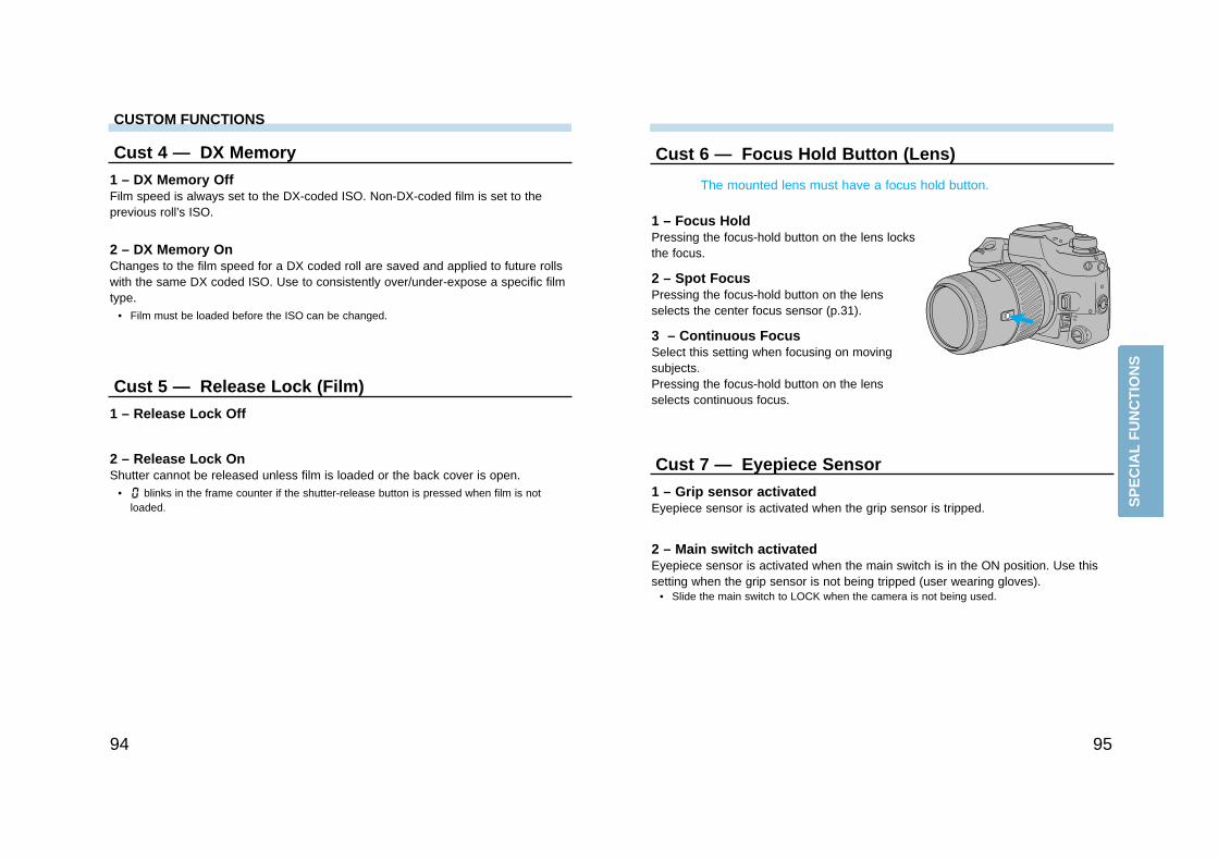
1 – Focus HoldPressing the focus-hold button on the lens locksthe focus.
2 – Spot FocusPressing the focus-hold button on the lensselects the center focus sensor (p.31).
The mounted lens must have a focus hold button.
3 – Continuous FocusSelect this setting when focusing on movingsubjects.Pressing the focus-hold button on the lensselects continuous focus.
Cust 7 — Eyepiece Sensor
1 – Grip sensor activatedEyepiece sensor is activated when the grip sensor is tripped.
2 – Main switch activatedEyepiece sensor is activated when the main switch is in the ON position. Use thissetting when the grip sensor is not being tripped (user wearing gloves).
• Slide the main switch to LOCK when the camera is not being used.
Cust 4 — DX Memory
1 – DX Memory OffFilm speed is always set to the DX-coded ISO. Non-DX-coded film is set to theprevious roll’s ISO.
2 – DX Memory OnChanges to the film speed for a DX coded roll are saved and applied to future rollswith the same DX coded ISO. Use to consistently over/under-expose a specific filmtype.
• Film must be loaded before the ISO can be changed.
Cust 5 — Release Lock (Film)
1 – Release Lock Off
2 – Release Lock OnShutter cannot be released unless film is loaded or the back cover is open.
• blinks in the frame counter if the shutter-release button is pressed when film is notloaded.
CUSTOM FUNCTIONS
SP
EC
IAL
FU
NC
TIO
NS
97
Cust 11 — Bracketing Sequence
1 – Metered exposure, Underexposure(s), Over-exposure(s)• A 5 frame bracket in 1/2EV increments is exposed in the following order…
Normal ➝ -0.5EV ➝ +0.5EV ➝ -1.0EV ➝ +1.0EV
2 – Underexposure(S), Metered exposure, Over-exposure(s)• A 5 frame bracket in 1/2EV increments is exposed in the following order…
-1.0EV ➝ -0.5EV ➝ Normal ➝ +0.5EV ➝ +1.0EV
Cust 12 — Rewind Speed
1 – Fast RewindRewinds a 36 exposure roll in approximately 6 seconds.
2 - Slow (silent) RewindRewinds a 36 exposure roll in approximately 9 seconds.
96
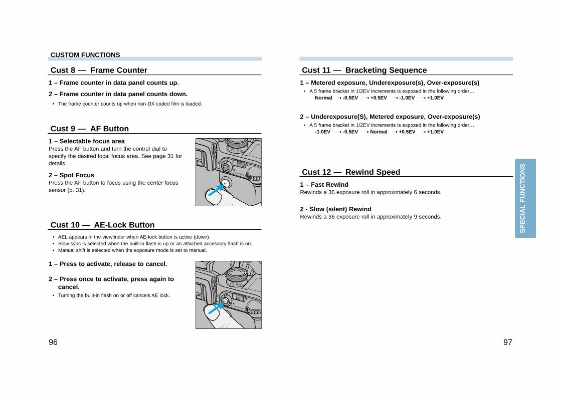
Cust 9 — AF Button
1 – Selectable focus areaPress the AF button and turn the control dial tospecify the desired local focus area. See page 31 fordetails.
2 – Spot FocusPress the AF button to focus using the center focussensor (p. 31).
Cust 10 — AE-Lock Button
1 – Press to activate, release to cancel.
2 – Press once to activate, press again tocancel.
• Turning the built-in flash on or off cancels AE lock.
• AEL appears in the viewfinder when AE-lock button is active (down).• Slow sync is selected when the built-in flash is up or an attached accessory flash is on.• Manual shift is selected when the exposure mode is set to manual.
Cust 8 — Frame Counter
1 – Frame counter in data panel counts up.
2 – Frame counter in data panel counts down.• The frame counter counts up when non-DX coded film is loaded.
CUSTOM FUNCTIONS
SP
EC
IAL
FU
NC
TIO
NS
9998
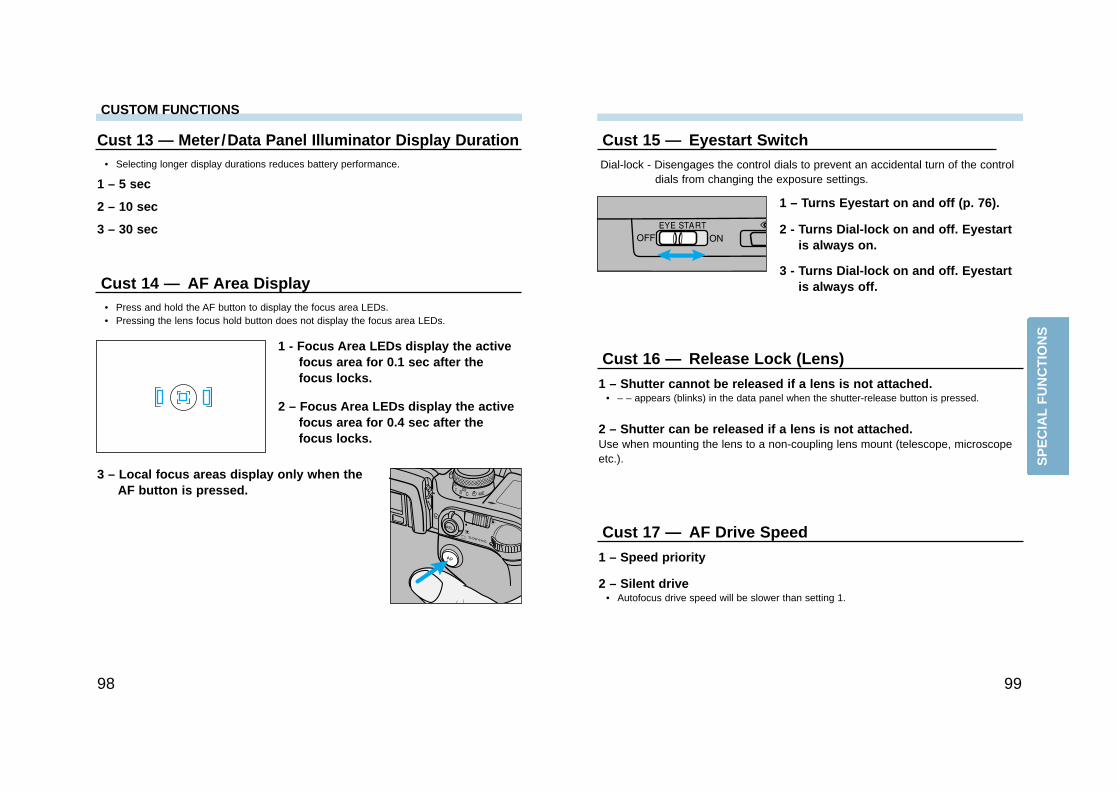
Cust 15 — Eyestart Switch
1 – Turns Eyestart on and off (p. 76).
2 - Turns Dial-lock on and off. Eyestartis always on.
3 - Turns Dial-lock on and off. Eyestartis always off.
Dial-lock - Disengages the control dials to prevent an accidental turn of the controldials from changing the exposure settings.
Cust 16 — Release Lock (Lens)
1 – Shutter cannot be released if a lens is not attached.• – – appears (blinks) in the data panel when the shutter-release button is pressed.
2 – Shutter can be released if a lens is not attached.Use when mounting the lens to a non-coupling lens mount (telescope, microscopeetc.).
Cust 17 — AF Drive Speed
1 – Speed priority
2 – Silent drive• Autofocus drive speed will be slower than setting 1.
Cust 13 — Meter /Data Panel Illuminator Display Duration
1 – 5 sec
2 – 10 sec
3 – 30 sec
• Selecting longer display durations reduces battery performance.
Cust 14 — AF Area Display
1 - Focus Area LEDs display the activefocus area for 0.1 sec after thefocus locks.
2 – Focus Area LEDs display the activefocus area for 0.4 sec after thefocus locks.
3 – Local focus areas display only when theAF button is pressed.
• Press and hold the AF button to display the focus area LEDs. • Pressing the lens focus hold button does not display the focus area LEDs.
CUSTOM FUNCTIONS
SP
EC
IAL
FU
NC
TIO
NS
101100
• The aperture and shutter speed change in 1/2 or 1/3 EV increments depending on theposition of the exposure compensation dial.
• Flash can not be used with the PA and PS modes.- Built-in and accessory flashes will not fire when the PA and PS modes are active.- PA and Ps modes can not be selected when appears in the viewfinder.
• If the shutter speed or aperture blink, the required setting is not available. Turn the controldial until the blinking stops.
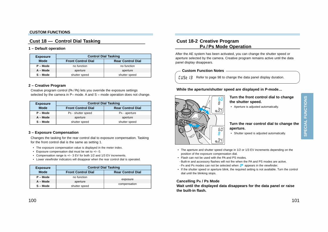
Cust 18-2 Creative ProgramPA / Ps Mode Operation
While the aperture/shutter speed are displayed in P-mode…
Turn the front control dial to changethe shutter speed.• Aperture is adjusted automatically.
Cancelling PA / Ps ModeWait until the displayed data disappears for the data panel or raisethe built-in flash.
After the AE system has been activated, you can change the shutter speed oraperture selected by the camera. Creative program remains active until the datapanel display disappears.
Cust 18 — Control Dial Tasking
1 – Default operation
2 – Creative Program
3 – Exposure Compensation
Creative program control (PA / Ps) lets you override the exposure settingsselected by the camera in P– mode. A and S – mode operation does not change.
• The exposure compensation value is displayed in the meter index.• Exposure compensation dial must be set to +/– 0.• Compensation range is +/– 3 EV for both 1/2 and 1/3 EV increments.• Lower viewfinder indicators will disappear when the rear control dial is operated.
Changes the tasking for the rear control dial to exposure compensation. Taskingfor the front control dial is the same as setting 1.
Control Dial Tasking
no function
aperture
shutter speed
Front Control Dial Rear Control DialExposure
Mode
P – Mode
A – Mode
S – Mode
no function
aperture
shutter speed
Turn the rear control dial to change theaperture.• Shutter speed is adjusted automatically.
Control Dial Tasking
Ps - shutter speed
aperture
shutter speed
Front Control Dial Rear Control DialExposure
Mode
P – Mode
A – Mode
S – Mode
PA - aperture
aperture
shutter speed
Control Dial Tasking
no function
aperture
shutter speed
Front Control Dial Rear Control DialExposure
Mode
P – Mode
A – Mode
S – Mode
exposure
compensation
Refer to page 98 to change the data panel display duration.
Custom Function Notes
CUSTOM FUNCTIONS
SP
EC
IAL
FU
NC
TIO
NS
102
APPENDIX
Cust 19 — Control Dial - Exchanged Control
1 – Unchanged from Cust 18.
2 – Front and rear control dial functions exchanged.• Control dial tasking does not change for bracketing, data memory, and custom functions.
Cust 20 — Flash Metering
1 – 4-Segment Flash Metering (p. 63)
2 – Average meteringAll flash metering segments are weighted evenly.
3 – Spot MeteringFlash is metered by the segment corresponding to the currently selected LocalFocus Area.
• Do not recompose the image after locking focus. Flash exposure is TTL metered by thesegment used to lock focus.
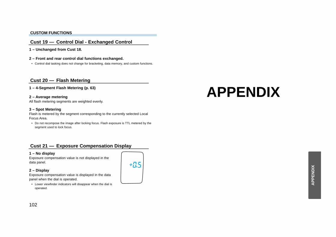
Cust 21 — Exposure Compensation Display
1 – No displayExposure compensation value is not displayed in thedata panel.
2 – DisplayExposure compensation value is displayed in the datapanel when the dial is operated.
• Lower viewfinder indicators will disappear when the dial isoperated.
CUSTOM FUNCTIONS
AP
PE
ND
IX
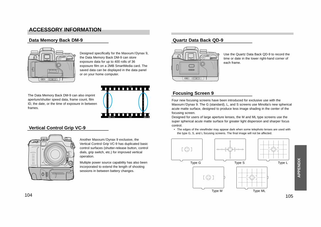
ACCESSORY INFORMATION
105104
Quartz Data Back QD-9
Focusing Screen 9
Data Memory Back DM-9
Vertical Control Grip VC-9
Use the Quartz Data Back QD-9 to record thetime or date in the lower right-hand corner ofeach frame.
Designed specifically for the Maxxum/Dynax 9,the Data Memory Back DM-9 can storeexposure data for up to 400 rolls of 36exposure film on a 2MB SmartMedia card. Thesaved data can be displayed in the data panelor on your home computer.
Four new focusing screens have been introduced for exclusive use with theMaxxum/Dynax 9. The G (standard), L, and S screens use Minolta’s new sphericalacute matte surface, designed to produce less image shading in the center of thefocusing screen. Designed for users of large aperture lenses, the M and ML type screens use thesuper spherical acute matte surface for greater light dispersion and sharper focuscontrol.
• The edges of the viewfinder may appear dark when some telephoto lenses are used withthe type G, S, and L focusing screens. The final image will not be affected.
Another Maxxum/Dynax 9 exclusive, theVertical Control Grip VC-9 has duplicated basiccontrol surfaces (shutter-release button, controldials, grip switch, etc.) for improved verticaloperation.
Multiple power source capability has also beenincorporated to extend the length of shootingsessions in between battery changes.
Type LType G
Type M
Type S
The Data Memory Back DM-9 can also imprintaperture/shutter speed data, frame count, filmID, the date, or the time of exposure in betweenframes.
AP
PE
ND
IX
Type ML
EXPOSURE WARNINGSACCESSORY INFORMATION
107106
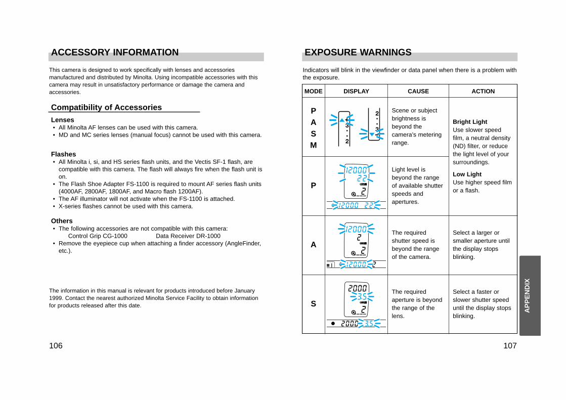
MODE DISPLAY CAUSE ACTION
PASM
Scene or subjectbrightness isbeyond thecamera’s meteringrange.
Bright LightUse slower speedfilm, a neutral density(ND) filter, or reducethe light level of yoursurroundings.
Low LightUse higher speed filmor a flash.
P
Light level isbeyond the rangeof available shutterspeeds andapertures.
A
The requiredshutter speed isbeyond the rangeof the camera.
S
The requiredaperture is beyondthe range of thelens.
Select a faster orslower shutter speeduntil the display stopsblinking.
Indicators will blink in the viewfinder or data panel when there is a problem withthe exposure.
This camera is designed to work specifically with lenses and accessoriesmanufactured and distributed by Minolta. Using incompatible accessories with thiscamera may result in unsatisfactory performance or damage the camera andaccessories.
Lenses• All Minolta AF lenses can be used with this camera. • MD and MC series lenses (manual focus) cannot be used with this camera.
Compatibility of Accessories
Flashes• All Minolta i, si, and HS series flash units, and the Vectis SF-1 flash, are
compatible with this camera. The flash will always fire when the flash unit ison.
• The Flash Shoe Adapter FS-1100 is required to mount AF series flash units(4000AF, 2800AF, 1800AF, and Macro flash 1200AF).
• The AF illuminator will not activate when the FS-1100 is attached.• X-series flashes cannot be used with this camera.
Others• The following accessories are not compatible with this camera:
Control Grip CG-1000 Data Receiver DR-1000• Remove the eyepiece cup when attaching a finder accessory (AngleFinder,
etc.).
The information in this manual is relevant for products introduced before January1999. Contact the nearest authorized Minolta Service Facility to obtain informationfor products released after this date.
AP
PE
ND
IX
Select a larger orsmaller aperture untilthe display stopsblinking.
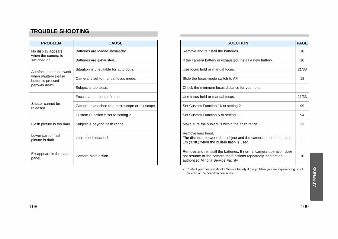
TROUBLE SHOOTING
109108
SOLUTION PAGE
Remove and reinstall the batteries.
If the camera battery is exhausted, install a new battery.
10
10
18
-
99
• Contact your nearest Minolta Service Facility if the problem you are experiencing is notcovered or the condition continues.
Use focus hold or manual focus.
Slide the focus-mode switch to AF.
Check the minimum focus distance for your lens.
21/33
Use focus hold or manual focus.
Set Custom Function 16 to setting 2.
21/33
Set Custom Function 5 to setting 1. 94
Make sure the subject is within the flash range. 23
Remove lens hood.The distance between the subject and the camera must be at least1m (3.3ft.) when the built-in flash is used.
-
Remove and reinstall the batteries. If normal camera operation doesnot resume or the camera malfunctions repeatedly, contact anauthorized Minolta Service Facility.
10
PROBLEM CAUSE
No display appearswhen the camera isswitched on.
Batteries are loaded incorrectly.
Batteries are exhausted.
Autofocus does not workwhen shutter-releasebutton is pressedpartway down.
Situation is unsuitable for autofocus.
Camera is set to manual focus mode.
Subject is too close.
Shutter cannot bereleased.
Focus cannot be confirmed.
Camera is attached to a microscope or telescope.
Custom Function 5 set to setting 2.
Flash picture is too dark. Subject is beyond flash range.
Lower part of flashpicture is dark.
Lens hood attached.
Err appears in the datapanel.
Camera Malfunction
AP
PE
ND
IX
CARE AND STORAGE
111110
Questions and Service• If you have questions about your camera, contact your local camera dealer
or write to the Minolta distributor in your area.• Before shipping your camera for repair, please contact an authorized
Minolta Service Facility for details.• Settings made or saved by the user, including Data Memory or Custom
Functions, may be lost during repair.
Cleaning• If the camera or lens barrel is dirty, wipe it gently with a soft, clean, dry
cloth. If the camera or lens comes in contact with sand, gently blow away looseparticles - wiping may scratch the surface.
• To clean the lens surface, first brush away any dust or sand then, ifnecessary, moisten a lens tissue with lens cleaning fluid and gently wipethe lens in a circular motion, starting from the center.
• Never place lens fluid directly on the lens.• Never touch the interior of the camera, especially the shutter and mirror,
doing so may impair their alignment and movement.• Dust on the mirror will not affect the exposure but may affect the focus. Use
a blower brush to remove dust from or around the mirror.• Never use compressed air to clean the camera’s interior, it may cause
damage to sensitive interior parts.• Never use organic solvents to clean the camera.• Never touch the lens surface with your fingers.
Before Important Events• Check the camera’s operation carefully, or take test photographs.• Minolta is not responsible for any loss that may occur due to an equipment
malfunction.
Operating Temperature and Conditions• This camera is designed for use from –20 to 50 °C (4 to 122 °F).• Never leave your camera where it may be subjected to extreme
temperatures such as the glove compartment of a car.• Data panel response time will be slow at colder temperatures. The display
will temporarily darken at higher temperatures, but will restore when thetemperature normalizes.
• This camera is not waterproof or splashproof. When using the camera inthe rain, protect the camera and the lens.
• Never subject the camera to extreme humidity.• To prevent condensation from forming, place the camera in a sealed plastic
bag when bringing it from cold environment to a warm environment. Allow itto come to room temperature before removing it from the bag.
• The low-battery symbol may appear even with fresh batteries depending onthe storage conditions. To restore camera power, repeat turning the cameraon and off.
• Battery capacity decreases at colder temperatures. Keep your camera andspare batteries in a warm inside pocket when shooting in cold weather.Batteries will regain some of their capacity when warmed to normaloperating temperature.
• Tape over the exposure-mode and exposure-compensation dials if the filmneeds to be removed from the camera in a darkroom or changing bag dueto a drive problem. Fogging may occur if the luminous dials are notcovered.
StorageWhen storing your camera for extended periods,
• Always attach the protective caps.• Store in a cool, dry, and well-ventilated area away from dust and chemicals
such as moth balls. For long periods, place the camera in an airtightcontainer with a silica gel drying agent.
• Periodically release the camera’s shutter to keep it operating properly.• Before using after prolonged storage, check the camera’s operation to
make sure it is functioning properly.
AP
PE
ND
IX

SPECIFICATIONS
113112
Specifications are based on the latest information available at the time of printingand are subject to change without notice.
Camera Type: 35mm SLR with built-in flash, autoexposure (AE), andomni-dimensional predictive autofocus (AF)
Lens Mount: Minolta A-type bayonet mountViewfinder*: Eye level, fixed pentaprism, 100% field of viewMagnification*: 0.73X
* With a 50mm lens focused at infinity.Focusing Screen: Spherical matte, user interchangeable screens available.Diopter: -1 diopter, Adjustment: -3 – +1
ShutterType: Electronically-controlled, vertical-traverse, focal-plane typeSpeeds: 30 sec. - 1/12000 sec., bulbFlash sync speed: 1/300 or slower (synchronizes with all speeds in HSS
mode).FocusType: TTL phase-detection system, multi metering with cross hair
type CCD line sensor metering cell. Autofocus and manualfocus modes.
AF Sensitivity Range: EV -1 to18 (ISO 100)AF Illuminator: Built-in 3 beam LED. Automatically activated in low-light/
low-contrast situations.Range: 0.7 - 7m (With a standard 50mm lens.)
AF Control: Single-shot, continuous, automatic AF-mode selection.
ExposureModes: P, A, S, M (PA/Ps available as a Custom Function)Type: TTL metering; direct TTL metering for flashMetering Cell: Ambient:14-segment honeycomb, center weighted
average, spot (5.5 Ø)Flash: 4-segment SPC
Metering Range : 14-segment metering: EV 0-20, (ISO 100, f/1.4 lens) Center weighted average: EV 0-20,
Spot metering: EV 3 - 20 Film-speed Setting: Automatic: ISO 25 to 5000 for DX-coded film.
Manual: ISO 6 to 6400 in 1/3 EV increments.Flash: ISO 25 - 1000.
Film TransportLoading: Auto loadDrive Modes: Single frame and Continuous advance (2 or 5.5
frames/sec. (4.5 in continuous AF mode)), self-timer (10 or2 second), exposure bracketing (single frame orcontinuous advance), and multiple exposure.
Rewind: Auto rewind, manual start (Count-down display)High speed or Silent.
Frame counter: Forward (shows number of exposures taken)
Built-in FlashGN: 12 (ISO 100 in meters)Coverage: 24mm angle of viewRecycling Time: Approx. 2.5 sec. (according to Minolta test methods)Modes: Fill-flash, Fill-flash with red-eye reduction, Flash Cancel,
Wireless flash, Slow-sync, and Rear-flash sync.
AdditionalPower: Two CR123A lithium batteriesBattery Performance:
24 Exposure Rolls 36 Exposure RollsFlash Use (%) 20 °C –20 °C 20 °C –20 °C
0 45 rolls 40 rolls 30 rolls 28 rolls50 23 rolls 15 rolls 15 rolls 10 rolls
100 14 rolls 9 rolls 9 rolls 6 rolls
Test Conditions : Lens (24-85 f/3.5-4.5) is focused from infinity to 2m three timesand the shutter-release button held partway down for tenseconds before each exposure.
• Battery performance will vary with usage conditions.• Exposures taken at a rate of 3 rolls/month for 24 exposure rolls,
2 rolls/month for 36 exposure rolls (starting with fresh batteries).
Dimensions (WxHxD): 155.0 x 111.0 x 75.0mm (WxHxD)Weight : 910g (w/o camera battery)
AP
PE
ND
IX
© 1999 Minolta Co., Ltd. under the Berne Convention andUniversal Copyright Convention
Printed in Japan 9222-2098-11 P-E106
Minolta Co., Ltd. 3-13, 2-Chome, Azuchi-Machi, Chuo-Ku, Osaka 541-8556, Japan
Minolta Europe GmbH Minoltaring 11, D-30855 Langenhagen, GermanyReparatur/Repair Senator-Helmken-Strasse 1, D-28279 Bremen, Germany
Minolta France S.A. 365 Route de Saint-Germain, F-78420 Carrieres-Sur-Seine, FranceMinolta (UK) Limited 7 Tanners Drive, Blakelands, Milton Keynes, MK14 5BU, EnglandMinolta Austria Ges. m.b.H. Amalienstrasse 59-61, A-1131 Wien, AustriaMinolta Camera Benelux B.V. Zonnebaan 39, P.O. Box 6000, NL-3600 HA Maarssen, The Netherlands
Belgium Branch Prins Boudewijnlaan 1, B-2550 Kontich, BelgiumMinolta (Schweiz) AG Riedstrasse 6, CH-8953 Dietikon, SwitzerlandMinolta Svenska AB Albygatan 114, S-171 54 Solna, Sweden
Finland Branch Niittykatu 6 PL 37, SF-02201 Espoo, FinlandMinolta Portugal Limitada Av. do Brasil 33-A, P-1700 Lisboa, PortugalMinolta Corporation
Head Office 101 Williams Drive, Ramsey, New Jersey 07446, U.S.A.Los Angeles Branch 11150 Hope Street Cypress, CA 90630, U.S.A.
Minolta Canada Inc.Head Office 369 Britannia Road East, Mississauga, Ontario L4Z 2H5, CanadaVancouver Branch 230-3771 Jacombs Road, Richmond, B.C. V6V 2L9, Canada
Minolta Hong Kong Limited Room 208, 2/F, Eastern Center, 1065 King’s Road, Quarry Bay, Hong KongMinolta Singapore (Pte) Ltd. 10, Teban Gardens Crescent, Singapore 608923Shanghai Minolta Optical Products Co., Ltd. 368 Minolta Road, Songjiang, Shanghai, China