ministim models ms-1b and ms-iva instruction manual - mainline
TRANSCRIPT
NOTE: Warranty Information
MUST Be Returned
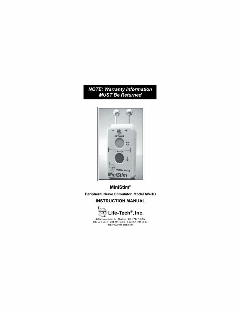
MiniStim®
Peripheral Nerve Stimulator, Model MS-1B
INSTRUCTION MANUAL
4235 Greenbriar Dr.• Stafford, TX 77477-3995
800-231-9841 • 281-491-6600 • Fax: 281-491-6646
http://www.life-tech.com
Life-Tech®, Inc.

OPERATING MANUAL
MODEL MS-1B
MiniStim®
M1042 Rev B
CAUTION: FEDERAL (USA) LAW RESTRICTS
THIS DEVICE TO SALE BY OR ON THE ORDER
OF A PHYSICIAN.
©2003, Life-Tech®, Inc. All rights reserved. No part of this manual maybe reproduced in any manner, in whole or in part without writtenpermission of Life-Tech®, Inc.
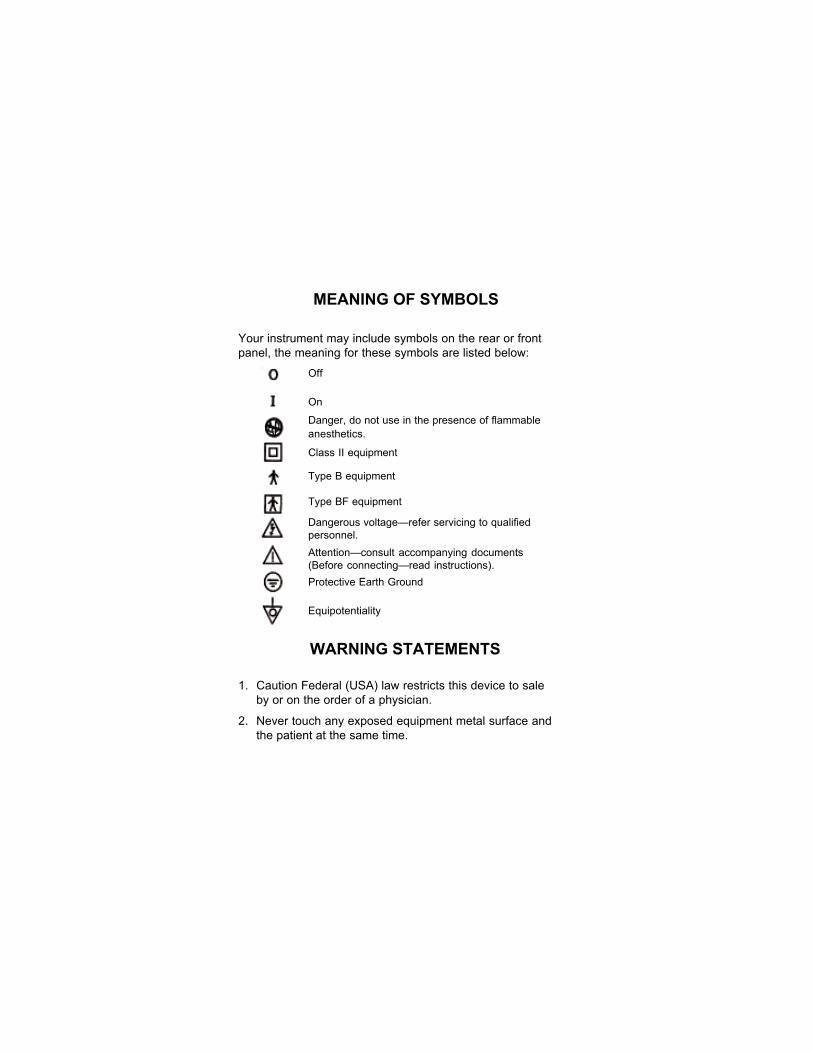
MEANING OF SYMBOLS
Your instrument may include symbols on the rear or front
panel, the meaning for these symbols are listed below:
Off
On
Danger, do not use in the presence of flammableanesthetics.
Class II equipment
Type B equipment
Type BF equipment
Dangerous voltage—refer servicing to qualifiedpersonnel.Attention—consult accompanying documents(Before connecting—read instructions).Protective Earth Ground
Equipotentiality
WARNING STATEMENTS
1. Caution Federal (USA) law restricts this device to sale
by or on the order of a physician.
2. Never touch any exposed equipment metal surface and
the patient at the same time.
HOW TO STERILIZE REUSABLE
PATIENT APPLIED PARTS
Never reuse or re-sterilize any patient applied part whose
original package was labeled with FOR ONE TIME USE,
SINGLE USE, DISPOSE AFTER USE or equivalent wording.
When in doubt about whether a patient applied part can be re-
sterilized, always consider it for one time use. The following
sterilization procedure is intended for removable, reusable
patient applied parts manufactured by Life-Tech (e.g., lead
wires). For a product that is sold by Life-Tech but not manufac-
tured by Life-Tech, refer to the sterilization procedures in that
product’s operating manual where appropriate.
DO NOT STERILIZE THE INSTRUMENT. To sterilize reusable
patient applied parts manufactured by Life-Tech, follow these
directions.
1. Place each part in a suitable vented sterilization pouch
(e.g., with a Tyvak side or port). Include a sterility indicator
designed for use with Ethylene Oxide and heat seal the
package with a device specifically designed for this
purpose.
2. Place the sealed packages in a sterilization chamber
designed for 100% ethylene oxide gas. After loading the
packages according to the sterilization chamber
manufacturer’s directions, close and secure the chamber
door.

3. Evacuate the sterilization chamber to a pressure of 0.01
atmospheres (7.6 mm Hg.).
4. Fill the sterilization chamber with 100% ethylene oxide gas
until the chamber pressure reaches 0.2 atmospheres (152
mm Hg).
5. Increase the sterilization chamber temperature to 48°C.
6. Maintain the sterilization chamber temperature at 48°C for
210 minutes (3.5 hours).
7. Reduce the sterilization chamber temperature to room
temperature. Purge ethylene oxide from the sterilization
chamber according to manufacturer’s directions and local
environmental regulations.
8. After sterilization, place the sealed packages in a quaran-
tined, ventilated area away from human contact for at least
two days to allow any residual ethylene oxide gas to
disperse. Follow local environmental regulations in
selecting the area and posting necessary cautionary
statements.
9. Examine each sealed package’s sterility indicator. Discard
or re-sterilize any part if its sterility indicator is negative or
the package is broken or opened. Store the sterilized
packages in a cool, dry place.

Sterilization chamber conditions may be affected by age, lack
of periodic re-calibration, metering errors or other problems.
The effectiveness of the sterilization procedure with your
specific equipment should be validated by an independent,
accredited testing laboratory to certify sterility and package
integrity after sterilization.
Check with a local accredited laboratory for further guidance.
Never make the assumption that re-sterilized patient applied
parts are sterile until sterility certification has been estab-
lished. Life-Tech assumes no responsibility that this steriliza-
tion procedure for patient applied parts will be effective with
your specific sterilization equipment.
Independent sterility certification by an accredited testing
laboratory is the only validation method that can establish this
level of confidence.
PRECAUTIONS
Before using the instrument, please read these operating
instructions carefully. Take special care to follow the warnings
indicated on the instrument as well as safety suggestions
below. Refer to this manual for additional information where
appropriate.
Safety
1. Not Recommended for use while operating Electro-
surgical equipment.
2. Danger: Risk of explosion if used in the presence of
flammable anesthetics.
Environment
1. Liquid and Moisture: Do not situate unit where water can
fall into the instrument.
2. Heat: The unit should be situated away from heat sources
such as radiators and the like. It also should not be placed
in temperatures less than 0°C (32°F) or greater than 45°C
(113°F).
Placement
1. Foreign Material: Care should be taken so that objects do
not fall onto and liquids are not spilled into the instrument.
Do not subject this instrument to excessive smoke, dust,
mechanical vibration, or shock.
2. Magnetism: The instrument should be situated away from
equipment or devices that generate strong magnetism.
3. Stacking: Do not place any heavy objects on top of the
instrument.
Service
1. Damaging Requiring Service: The unit should be
serviced by qualified service personal when:
a. Objects have fallen onto or liquid has been spilled into
the instrument; or
b. the instrument has been exposed to rain or moisture; or
c. the instrument does not appear to operate normally or
exhibits a marked change in performance; or
d. the unit has been dropped, or the enclosure damaged.
2. Servicing: The user should not attempt to service the unit
beyond that described in the Operating Manual unless
directed by Life-Tech Service Personnel. All other servicing
should be referred to qualified service personnel.

TABLE OF CONTENTS
Section Description Page
1 General Description and Specifications
1.1 Introduction ................................................... 1
1.2 Specifications ................................................ 2
2 Panel Markings and Controls .............................. 3
3 Operating Procedures
3.1 General Precautions and
Contraindications .......................................... 4
3.2 Use of Surface Electrodes for
Transcutaneous Stimulation ......................... 5
3.3 Use of DP-MTP Bipolar Probe ...................... 9
4 Maintenance
4.1 General ....................................................... 10
4.2 Battery Replacement .................................. 10
4.3 Cleaning and Disinfection ........................... 10
5 Accessories and Spare Parts ........................... 12
6 Limited Warranty ................................................ 13
LIST OF ILLUSTRATIONS
Figure Description Page
2.1 MS-1B Front Panel Controls ...................................... 3
3.1 Wrist Motor Points ...................................................... 6
3.2 Facial Motor Points .................................................... 7
3.3 Attachment of EL-2MTP Leadwires or DP-MTP
Bipolar Probe .............................................................9

SECTION 1
GENERAL DESCRIPTION AND
SPECIFICATIONS
1.1 Introduction
The MiniStim is a battery powered Peripheral Nerve
Stimulator for monitoring the effects of skeletal muscle
relaxants on the neuromuscular function.
MiniStim is a constant-voltage stimulator producing 0.20
millisecond square wave pulses with a maximum no-load
output of 300 volts. The fixed stimulus voltage is ad-
equate to ensure supramaximal subcutaneous stimulation
of peripheral nerves in all but the most obese patients.
Pulse delivery is indicated by flashing of the green LED.
Two push-button controls set the stimulus pulse rate at
either 2 pulses per second (for Twitch or Train-of-Four), or
50 pulses per second for eliciting Tetanus.
1

1.2 Specifications
Size (WXDXH): 1.5" x 0.9" x 2.6" (3.8cm x 2.3cm x 6.6cm)
Weight: 3 oz (85gm) including battery
Output Voltage: 300V ± 30V (open circuit)
Output Current: 30 mA (2K ohms or less resistive load)
Pulse Width: 200 micoseconds
Pulse Risetime: Less than 6 microseconds open circuit
Twitch Pulse Frequency: Two pulses per second
Tetanus Pulse Frequency: 50Hz
Train-of-Four: Hold Twitch down for four pulses
Battery: One 7.5 volt alkaline battery
2
3
SECTION 2
PANEL MARKINGS AND CONTROLS
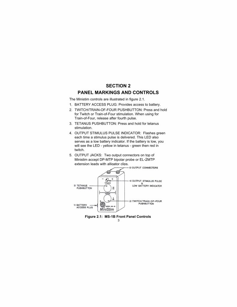
The Ministim controls are illustrated in figure 2.1.
1. BATTERY ACCESS PLUG: Provides access to battery.
2. TWITCH/TRAIN-OF-FOUR PUSHBUTTON: Press and hold
for Twitch or Train-of-Four stimulation. When using for
Train-of-Four, release after fourth pulse.
3. TETANUS PUSHBUTTON: Press and hold for tetanus
stimulation.
4. OUTPUT STIMULUS PULSE INDICATOR: Flashes green
each time a stimulus pulse is delivered. This LED also
serves as a low battery indicator. If the battery is low, you
will see the LED - yellow in tetanus - green then red in
twitch.
5. OUTPUT JACKS: Two output connectors on top of
Ministim accept DP-MTP bipolar probe or EL-2MTP
extension leads with alligator clips.
Figure 2.1: MS-1B Front Panel Controls
SECTION 3
OPERATING PROCEDURES
3.1 General Precautions and Contraindications
Explosive Atmospheres. MiniStim is not intended for
use in explosive atmospheres.
Microshock Hazard. In patients with pacemakers or
cardiac abnormalities, the physician in charge of the
patient must approve the use of the MiniStim.
Battery Leakage. If the unit is going to be stored for
a prolonged period of time, we recommend that you
remove the battery to protect the unit from
damage caused by battery chemical leakage.
Neuromuscular Disease. Patients with symptoms of
myasthenia gravis, Bell’s palsy, muscle weakness, or
paralysis may not respond normally to nerve stimulation.
Skin Disease. The electrodes should not be applied
to an area of the skin where injury, inflammation or
other pathology is present or suspected.
Tetanic Stimulation. The Twitch and Train-of-Four
stimulus is usually well tolerated in awake patients;
however, tetanic stimulation can be uncomfortable or
fully conscious patients. It is recommended that
tetanus stimulation be performed only after anesthesia.
Needle Electrodes. The Ministim is intended only for
surface stimulation. DO NOT USE needle electrodes
with Ministim or needle burns may occur.
Nerve Location. MiniStim is not intended for nerve
location for regional block. The Tracer, EasyStim, and
MaxiStim are specifically designed for this purpose.
4
3.2 Use of Surface Electrodes for Transcutaneous
Stimulation
1. Cleaning the Skin. Clean the skin with alcohol or
skin cleaner, then wipe the skin dry.
2. Location of the Electrodes. The stimulating
electrodes are usually placed on a motor point of
the median or ulnar nerve at the wrist or on a
motor point of the facial nerve. The negative
electrode should be placed on the motor point,
with the positive electrode nearby.
As shown in Figure 3.1, the median nerve motor
point is located 10-20 mm proximal to the distal
palmar crease between the tendons of the
palmaris longus and the flexor carpi radialis; the
ulnar nerve motorpoint is located 15-25 mm
proximal to the pisiform bone on the thumb-side of
the flexor carpi ulnaris tendon.
5
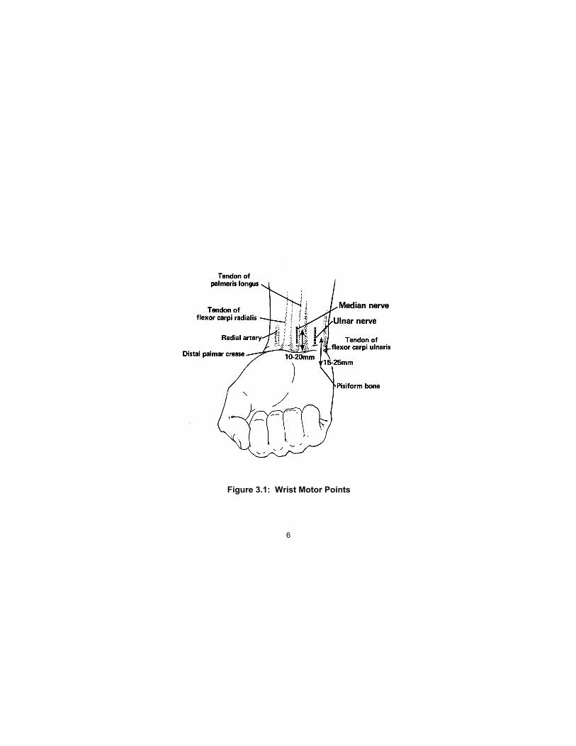
Figure 3.1: Wrist Motor Points
6
7
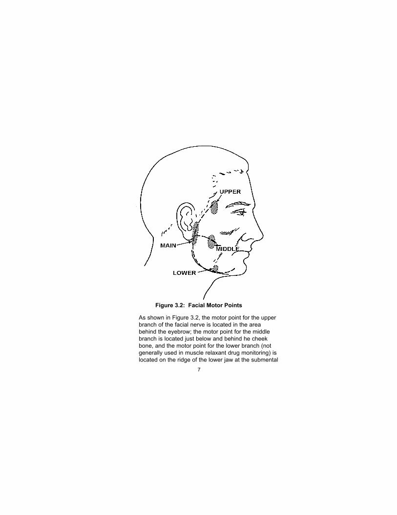
Figure 3.2: Facial Motor Points
As shown in Figure 3.2, the motor point for the upper
branch of the facial nerve is located in the area
behind the eyebrow; the motor point for the middle
branch is located just below and behind he cheek
bone, and the motor point for the lower branch (not
generally used in muscle relaxant drug monitoring) is
located on the ridge of the lower jaw at the submental

notch. The main submental motor point is located
just anterior to the lower half of the pinna.
Stimulation of the:
• Upper branch causes twitching of the eyebrow
and eyelid.
• Middle branch causes twitching of the muscles
lateral to and above the mouth.
• Lower branch causes twitching of the chin.
• Main motor point causes twitching of the facial
muscles supplied by all branches of the facial
nerve, but usually preferentially elicits twitching
in the vacicity of the eyebrow.
If one of the branch motor points is used, care
should be taken that the muscle twitch which is
monitored is located some distance away from the
stimulating (negative) electrode, to avoid the
possibility of direct muscle stimulation.
3. Attachment of Extension Leads and surface
electrodes. To use the MiniStim with the EL-2MTP
extension lead and surface electrodes (Figure 3.3):
a. Remove the DP-MTP Bipolar Probe and insert
the color coded connectors of the EL-2MTP
into the connector jacks on the top panel of the
MiniStim.
b. Then, open the alligator clip and place it
around the snap on the electrode. Be sure to
align the alligator clips so they do not touch
each other, thereby shorting the output of the
Stimulator.
8
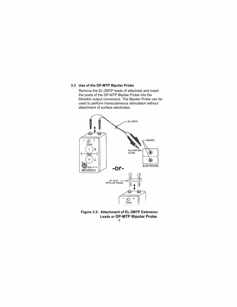
3.3 Use of the DP-MTP Bipolar Probe
Remove the EL-2MTP leads (if attached) and insert
the posts of the DP-MTP Bipolar Probe into the
Ministim output connectors. The Bipolar Probe can be
used to perform transcutaneous stimulation without
attachment of surface electrodes.
9
Figure 3.3: Attachment of EL-2MTP Extension
Leads or DP-MTP Bipolar Probe
SECTION 4
MAINTENANCE
4.1 General
Other than replacing the battery periodically and keeping the
unit free of debris and contaminants, the Ministim requires no
user maintenance, and is not user serviceable.
4.2 Battery Replacement
1. Using a coin or screwdriver, unscrew the Battery Ac-
cess Plug (Figure 2.1).
2. Tap the unit gently against your palm to dislodge the
battery into your hand.
3. Replace with a fresh battery taking care to match
polarity signs located on the back of the Ministim.
4. Screw the Battery Access Plug back into the Ministim.
NOTE: Please note that the battery supplied with this
unit is an alkaline battery, therefore battery life will be
approximately 1/3 of mercury batteries that were
previously provided (discontinued due to environmental
regulations) or an average of 8 months with normal use.
We suggest spare batteries be available for each unit.
4.3 Cleaning & Disinfection
To clean the Ministim:
1. Mix approximately a 1% solution of mild detergent
(e.g., Ivory liquid) and water (10cc of detergent
mixed with 1 liter of water).
2. Turn the unit off.
10
3. Dampen a clean, soft cloth with the fresh detergent
solution and wipe to remove visible contaminants
from the outside of the unit. NEVER pour or spray
cleaning solution directly onto the unit, or submerge
it in a solution.
4. Dampen another clean, soft cloth with sterile or
distilled water and wipe to remove all residual
detergent solution.
5. Dry thoroughly with another clean, dry cloth.
To disinfect the Ministim:
1. Leave the unit off.
2. Dampen a clean soft cloth with either 90% isopropyl
alcohol, or any commercially available solution
intended for surface disinfection of medical electrical
equipment, and wipe the exterior surface thoroughly.
If solution is in spray form, spray it onto the cloth.
NEVER pour or spray disinfecting solution directly
onto the unit, or submerge the unit in the solution.
3. Allow the solution to air dry for at least one minute,
then dry thoroughly with another clean, dry cloth.
11

SECTION 5
ACCESSORIES AND
SPARE PARTS
12
EL-2MTP
DP-MTP
CC-M
H1000
Extension Leads
Two-foot long paired leads with
touch proof connectors at one end
and alligator clips at the other
Bipolar Probes
Paired ball probes
Carrying Case
Ministim vinyl case
Battery
Alkaline Battery

SECTION 6
LIMITED WARRANTY
Refer to LIMITED WARRANTY card
for complete information.
13
