miniplex-42usb nmea-0183 multiplexer manual · miniplex-42usb nmea-0183 multiplexer manual miniplex...
TRANSCRIPT

MiniPlex-42USB NMEA-0183 multiplexer
Manual
MiniPlex-42USB, V2.0 Firmware V2.8.1 Art.no.: 104 © CustomWare, 2008

2
Introduction The MiniPlex-42USB is a four-channel NMEA multiplexer, enabling the connection of multiple NMEA-0183 instruments to each other and a computer. Available are four NMEA inputs (listener-ports), two NMEA outputs (talker-ports) and one USB port for connection with a computer. The multiplexer offers many features for manipulating incoming NMEA data like sentence filtering, real time mode, talker ID modification and SeaTalk to NMEA translation in order to read data from Raymarine instruments like the ST40, ST50 and ST60 series.
Wind
Multiplexer
Com-pass
GPS
Laptop
Auto-pilot
In 1
In 2
In 3
USB
Out 2
Operation The multiplexer reads NMEA sentences from the listener ports and stores them in a buffer, one for each input. The sentences are read from the buffers in a round robin fashion - one sentence at a time - giving each listener port equal priority. Each sentence is then sent to the talker ports and the USB port.
The speed of the listener ports is fixed to 4800 Baud (= bits per second), which equals 480 characters per second. When all listener ports receive data at this rate, the buffers will not be emptied in time and an overflow situation occurs. The red LED indicates this situation. When a buffer is full, a partially received sentence will be discarded, to ensure that the MiniPlex-41USB only sends complete and valid NMEA sentences.
There are three ways to resolve this overflow situation:
1. Configure the instruments on the listener ports to send less data or with greater intervals. It is often possible to disable non-relevant sentences.
2. Increase the speed of NMEA Out1 on the multiplexer. The maximum speed is 38400 Baud. From 19200 Baud and up (4 x 4800!) an overflow will never occur, except when the multiplexer is set to Hub Mode.
3. Many instruments do not allow selection of NMEA sentences to be output. In this case, use the NMEA sentence filter in the multiplexer to block unwanted sentences. Unwanted sentences are discarded immediately.
The multiplexer has two talker ports, ‘Out 1’ and ‘Out 2’. All received sentences from the listener ports are available on talker port ‘Out 1’. Talker port ‘Out 2’ can be configured either to output all received sentences from the listener ports and the USB port (Hub Mode), or only sentences from the USB port (Server Mode). See the table below.
NMEA In 1
NMEA In 2
NMEA In 3
NMEA In 4
USB In
NMEA Out 1 H/S H/S H/S H/S -
NMEA Out 2 H H H H H/S
USB Out H/S H/S H/S H/S -
H: Hub mode, S: Server mode

3
Connections
NMEA Listener Ports The multiplexer has four listener ports, ‘In 1’ to ‘In 4’. Each listener port should be connected to one instrument only. These inputs are galvanically isolated from the multiplexer, as specified in the NMEA-0183 standard.
Connect the ‘a’ and ‘b’ terminals of the listener port on the multiplexer to the ‘a’ and ‘b’ terminals of the talker port on the instrument. Other designations used are for instance ‘Data +’ and ‘Data -’, ‘TX+’ and ‘TX-’ , ‘Out +’ and ‘Out –’ or ‘ve+’ and ‘ve-’.
Some instruments have single ended talker ports, with only one data terminal. Connect this terminal to the ‘a’ terminal on the multiplexer, and connect the ‘b’ terminal on the multiplexer with the ground of the instrument. The latter is often combined with the power supply ground.
Instrument Multiplexer Instrument Multiplexer
TX
GND
Differential Single-ended
Out A / +
Out B / -
In A
In B
In A
In B
NMEA Talker Ports Both talker ports can be connected to up to four instruments. Connect the ‘a’ and ‘b’ terminals of the talker port on the multiplexer to the ‘a’ and ‘b’ terminals of the listener port(s) on the instrument(s). Other designations used are for instance ‘Data +’ and ‘Data -’, ‘TX+’ and ‘TX-’ , ‘Out +’ and ‘Out –’ or ‘ve+’ and ‘ve-’.
Some instruments have single ended listener ports, with only one data terminal. Connect this terminal to the ‘a’ terminal on the multiplexer, and leave the ‘b’ terminal on the multiplexer unconnected. Connect the ‘Com’ terminal on the multiplexer with the instrument ground.
Multiplexer Instrument Multiplexer Instrument
Differential Single-ended
RX
GND
Out A
Out B
Out A
Out B
In A / +
In B / -
GNDGND
Multiplexer
Out A
Out B
GNDInstrument
In A / +
In B / -
Instrument
RX
GND
Instrument
In A / +
In B / -
Multiple instruments
The shield terminals (Shld) can be connected to the screen/shield of the cable, if present. This should always be done on one end of the cable only, preferable on the talker side.

4
SeaTalk SeaTalk® is a proprietary protocol developed by Raymarine®. This protocol is used for communication between Raymarine navigation instruments like the ST40, ST50 and ST60 series. To be able to use these instruments with commonly available navigation programs or to feed their data into other non-Raymarine instruments, the Seatalk data needs to be translated into NMEA. Even Raymarine's own navigation software, Raytech Navigator, needs this translation. The multiplexer can be connected to a SeaTalk network. It will translate all SeaTalk data required for navigation into NMEA sentences. NMEA Input 4 can be switched to SeaTalk mode and should be connected as follows:
SeaTalk cable
Multiplexer
Connecting a SeaTalk network
In 4A
In 4B
Red
Yellow
The screen of the Seatalk cable is not connected to the multiplexer.
USB Port The USB port connects the multiplexer to a computer or a USB hub with the supplied cable. A driver provides a virtual com port to allow navigation software to communicate with the multiplexer.
Power Supply The multiplexer is powered by the USB bus or from an externally supplied DC voltage from 8 to 35V and is protected against reversed polarity. The multiplexer automatically switches between the two power sources.
It is recommended to connect the multiplexer to the same power source or circuit breaker as the ships instruments and/or computer.
Driver Installation To use the multiplexer with your computer, a USB device driver needs to be installed. This driver creates a virtual COM port, which can be opened with any navigation software. Drivers are supplied for Windows 98 & ME, Windows 2000, Windows XP, Windows Vista and Max OS X.
Windows Installation When the multiplexer is connected to a USB port for the first time, Windows will detect new hardware and ask for a driver disk. Insert the supplied CD into the drive and follow the instructions on your screen. When asked to automatically search for drivers, answer no and choose the option to tell Windows where to find the driver. The driver can be found on the supplied CD, in de folder “USB Driver”. This folder contains subfolders with drivers for various operating systems.
The installation on Windows 2000 and XP is a two-step process. First, the driver for the multiplexer will be installed. Next, Windows will detect a USB Serial device and will install a second driver. On XP systems, there can be a delay of up to 10 seconds between the installation of both drivers, which sometimes leads to the conclusion that the installation is complete after the first driver is installed. This is not the case. On Vista and W2K systems, there is only very little delay.
When the installation is complete, a new virtual COM port will be created. This COM port is marked in MPX-Config as “COMx (vcp)” where ‘x’ is a number. Select this port in your navigation software.
If necessary, the number of this COM port can be changed in the Windows Device Manager. Click on the ‘+’ sign next to the entry marked as ‘Ports (COM & LPT)’. This will expand the entry to list all available COM ports on your computer. The port for the multiplexer is listed as ‘USB Serial Port (COMx)’ where ‘COMx’ is the name of the newly created serial port.

5
To change this port number, double click on the ‘USB Serial Port (COMx)’ entry to open the property page for this port. Next, select the ‘Port Settings’ tab and click on the ‘Advanced…’ button. In the appearing window the used port number can be changed. Do not change any other setting in this window.
It is possible to select a port number that is already present on the computer, like COM1. The original COM1 port will then be disabled as long as the multiplexer is connected to the computer. This feature allows the port number to be set in a low range from COM1 to COM4, to accommodate software that only allows COM1 to COM4 to be selected.
More than one multiplexer can be connected at the same time. Every new unit will create a new virtual COM port. The number of this port will always be assigned to the same unit.
Windows allows a maximum of 256 COM ports. Not all software may be compatible however with COM ports numbered above COM9.
When installing updated drivers, uninstall the original drivers first with the ‘Add/Remove Programs’ icon in the Control Panel or use the ‘Update Driver’ button on the ‘Driver’ page of the ‘USB Serial Port’ property-page.
Mac OS X Installation The OS X driver is available as a disk image file (.dmg) and can be found on the supplied CD in the ‘USB Driver’ folder. Run the installer by double clicking on the icon. Follow the instructions on the screen and reboot the computer when asked.
When the computer has rebooted, plug in the multiplexer. Then open System Preferences and select ‘Network’. You should now get the message ‘New Port Detected’. Click OK and select ‘Network Port Configurations’ from the Show list. The new port will be listed as ‘MiniPlex-xxxxxxxx’ where ‘xxxxxxxx’ represents the serial number of the multiplexer. Enable the port by checking the On box and clicking ‘Apply Now’. You can now exit ‘Network’ and use the multiplexer in your navigation software.

6
Configuration Various options can be configured on the multiplexer, using the supplied configuration program MPX-Config. There is no installation procedure for this utility, just start it from the CD or copy it to a suitable folder on the hard disk of your computer. The top part of MPX-Config shows the NMEA sentences that are received by the multiplexer. The bottom part shows the configuration controls.
The File menu allows you to store the configuration settings of the multiplexer to a file or load the configuration from a file. This file format is similar to the Windows INI file format, allowing editing the files with a text editor. See the Technical Reference section for an example of a configuration file.
The multiplexer is configured with proprietary NMEA sentences. MPX-Config sends these sentences to the multiplexer but they can also be issued with a terminal program. See the Technical Reference section for a complete reference of the supported proprietary sentences.
All configuration settings are stored in the multiplexer’s non-volatile memory. These settings are retained without power supply.
Screenshot of MPX-Config
Serial Port Before being able to configure the multiplexer, select the serial port to which the multiplexer is connected. The virtual port created by the driver is marked with ‘(vcp)’. The speed setting has no influence on the speed of the virtual serial port. It does however affect the speed of NMEA Out1. If you exit MPX-Config, the settings will be saved.

7
Read Configuration Every time you start MPX-Config, it will request the current configuration from the multiplexer. When this is unsuccessful (various controls on the MPX-Config window are greyed), you can manually request the current configuration with this button.
The status line on the bottom of the MPX-Config window will show the name of the multiplexer, the internal software version, the serial number and the optionally loaded configuration file.
Options Various options can be enabled on the multiplexer by checking one of the checkboxes as shown on the right.
Priority The Priority option assigns a priority to incoming NMEA data, based on which input channel it is received. The USB input has the highest priority, followed by NMEA In 1, 2, 3 and 4 in descending order. If for instance two GPS receivers are connected to input 1 and 2 and both GPS receivers output GPRMC sentences, only the sentence from the GPS on input 1 is passed. This feature can be useful to set up a second GPS as a backup for the main GPS.
The multiplexer only uses the sentence formatter (the ‘RMC’ part) for comparison. Another useful application is when a Loran-C receiver is used as a backup for the GPS. With the GPS connected to input 1 and the Loran-C receiver connected to input 2, the NMEA data from the GPS is passed while similar NMEA sentences (e.g. LCRMB, LCGLL) from the Loran-C are blocked. When the GPS fails, a timeout mechanism ensures that after 10 seconds the NMEA data from the Loran-C is passed through the multiplexer.
Please note that not every sentence from a lower priority input is blocked. When for instance the Loran-C outputs GLC sentences (which a GPS definitely does not), these are passed through the multiplexer too. The priority mechanism only works on sentences with a similar formatter (characters 3 to 5).
The following example shows what is passed and what not. The left column in the table shows the sentences from a GPS and the right column the sentences from a Loran-C. The sentences that are greyed in the table are blocked by the priority mechanism. The table shows that only the GLL and RMB sentences from the Loran-C are blocked. If it is necessary to block the remaining sentences from the Loran-C, the Sentence Filter can be used.
The priority mechanism can store up to 30 sentence types to determine their priority. The list is scanned every second and entries older than 10 seconds are removed. This ensures that sentence types on lower priority inputs are passed when their counterparts on higher priority inputs are no longer received.
Channel Numbers This option inserts channel number information in the NMEA stream that is output by the multiplexer. Each NMEA sentence that is output on the USB interface is preceded by a proprietary NMEA sentence ‘$PSMDCN’, to indicate on which NMEA input the following sentence was received. The following example shows that the IIGGA sentence was received on input 1, the GPGGA sentence on input 2, the IIGLL sentence on input 1 and the HEHDT sentence on input 3.
This channel number information is used by our utility VirtualPlex-1 to send NMEA sentences from a certain input port on the multiplexer to a specific virtual serial port.
GPS (In 1)
Loran-C (In 2)
GPGLL LCGLL
GPRMB LCRMB
GPGGA LCGLC
GPRMC LCBOD
$PSMDCN,1*1A $IIGGA,143357.999,5301.0061,N,00635.5479,E,1,06,1.9,90.0,M,,,,0000*2E $PSMDCN,2*19 $GPGGA,143357.999,5301.0061,N,00635.5479,E,1,06,1.9,90.0,M,,,,0000*39 $PSMDCN,1*1A $IIGLL,5301.0061,N,00635.5479,E,143357.999,A*22 $PSMDCN,3*18 $HEHDT,67.0,T*1E

8
In the example on the right, VirtualPlex-1 is configured to create a virtual serial port COM3, which is assigned to input channel 2 on the multiplexer. Applications that open COM3 will thus only receive NMEA sentences from input channel 2 on the multiplexer.
Channel ID’s The Channel ID’s option changes the talker ID of incoming NMEA sentences into ‘Mx’ where ‘x’ represents a number from 1 to 4. This number corresponds with the input channel on which the sentence was received. This feature can be useful when similar sensors are connected to the multiplexer and the software must be able to distinguish between the data from these sensors. A catamaran for instance could have a depth sensor in each hull, sending similar sentences to the navigation software.
HDG -> HDT This option changes an HDG sentence (magnetic heading) into an HDT sentence (true heading). If the HDG sentence contains a magnetic variation, it is used to calculate the true heading from the magnetic heading in the HDG sentence, otherwise the magnetic heading is just copied into the HDT sentence. This option can be used when a device like a Voyage Data Recorder needs a true heading from a gyrocompass while only a fluxgate compass is available.
Seatalk -> NMEA To enable translation of SeaTalk® into NMEA, check this option. SeaTalk is a proprietary protocol developed by Raymarine® and it is used for communication between Raymarine navigation instruments like the ST40, ST50 and ST60 series. To be able to use these instruments with commonly available navigation programs or to feed their data into other non-Raymarine instruments, the Seatalk data needs to be translated into NMEA. See the Technical Reference section for an overview of the SeaTalk data that is translated into NMEA.
Mode of Operation The MiniPlex-42USB can operate in three different modes: Server, Hub and Automatic. Basically, these modes determine which NMEA data is available on NMEA Out2.
Server mode: In this mode, the combination of computer and multiplexer acts as an NMEA server. Incoming NMEA data from NMEA In1 to In4 is sent to the computer on the USB port. Only NMEA data from the computer is available on NMEA Out2.
Hub mode: In Hub mode, the multiplexer acts as a hub where all NMEA data comes together and is sent out again. All incoming NMEA data, from NMEA In1 to In4 and the computer, is available on NMEA Out2. This mode has one limitation: since the NMEA data is sent to the USB port and NMEA Out2, the total throughput is limited by the speed of NMEA Out2, which is fixed to 4800 baud. Even when the USB port is set to 38400, the throughput will be 480 characters per second, the same as on NMEA Out2.
Auto mode: When Auto mode is selected, the multiplexer automatically switches between Hub- and Server mode, depending on the presence of computer generated data. When the computer sends NMEA data to the multiplexer (on the USB interface), the multiplexer is in Server mode. When no data is received on the USB interface for more than 10 seconds, the multiplexer will switch to Hub mode.

9
Auto mode is very useful when sailing alternately with our without a laptop. Consider a typical setup as shown below:
When the laptop is connected, it will receive all information from the instruments and the running navigation software is able to calculate the course to steer and drive the autopilot accordingly. Because the laptop is sending NMEA data, the multiplexer is in server mode and the autopilot will therefore receive information from the laptop only.
When the laptop is not connected, the multiplexer switches to in hub mode and sends all data from the intruments directly to the autopilot. This way, the autopilot will receive course information directly from the GPS.
NMEA Out1 is not affected by the mode setting. On this output, only NMEA data from the NMEA inputs is available. Since this output is connected in parallel with the USB port, it will operate at the same speed as the USB port. When the USB port is set to 38400 baud, NMEA Out1 will also run at 38400 baud.
Real-Time The Real-Time option bypasses the buffer for a specific channel. During normal operation, all incoming NMEA sentences are stored in a channel buffer, which holds approximately 2 seconds of NMEA. In situations with heavy NMEA traffic, these buffers can be filled up quite rapidly until an overflow occurs (read LED blinks). Normally an overflow situation is not dangerous, it merely means that every now and then an incoming NMEA sentence is discarded because the buffer has no room left to store the entire sentence.
However, when a fluxgate or gyrocompass is connected, which sends it’s position 10 or 20 times per second, the corresponding input buffer on the multiplexer is filled up constantly. Together with NMEA data from other instruments, the total amount of data passing through the multiplexer gets so high that almost all used inputs are in constant overflow, resulting in an unacceptable delay of information of up to 12 seconds. This renders the compass heading useless for an autopilot.
By enabling the Real-Time option on a channel that is connected to a compass, the buffer on that channel is bypassed and the NMEA data from the compass is passed through the multiplexer immediately. Some NMEA sentences from the compass will be discarded when the multiplexer is servicing another channel but the sentences that are passed are always up to date instead of 12 seconds delayed.
The overflow indicators on the MPX-Config screen can be used to determine which channel is causing the overflow. The LED corresponding to the compass channel will be lit almost continuously.
Running the multiplexer at a serial port speed of 19200 baud or higher will never result in overflow or long delays.
Wind
MiniPlex-42USB
Com-pass
GPS
Laptop
Auto-pilot
In 1
In 2
In 3
USB
Out 2

10
Talker ID The multiplexer allows you to change the talker ID of incoming sentences. The effect is the same as with the Channel ID option, but here you can specify the talker ID per input channel. Enter the desired talker ID in the edit box of the desired channel and press the Set button to send the setting to the multiplexer. Pressing the Read Configuration button will read the Talker ID settings from the multiplexer. To clear a talker ID, simply clear the edit box(es) and press the Set button. Please note that any combination of two characters can be used as talker ID, including spaces. Therefore, make sure you clear the edit box and not fill it with spaces if you want to clear a talker ID. With the setting as shown on the right, any NMEA sentence received on input channel 1 will get talker ID ‘II’. Thus a GPRMC sentence from a GPS will be changed into IIRMC.
Sentence Filter The sentence filter is a powerful feature that allows you to specify exactly which NMEA sentence may be received on any channel, including the USB interface. Up to 30 rules can be entered, either manually or by capturing the NMEA sentences received by the multiplexer.
Each filter rule consists of the address field of an NMEA sentence (2 characters for the talker ID and 3 characters for the sentence formatter like ‘GPRMC’) and an indicator for each channel (Inputs 1 to 4 and the PC). The indicator can be toggled between a pass sign ( ) and a block sign ( ) by clicking on it and determines whether that specific sentence will be passed or blocked by the multiplexer. Wildcards are allowed too, using the ‘-’ character.
An Example The first step is to fill the list with NMEA sentences to be filtered. This can be done automatically by pressing the ‘Capture’ button. All controls will be disabled during capture and the ‘Capture’ button changes to ‘Stop’.
Leave the capture mode running for approximately 10 seconds. By that time, all connected instruments will have sent NMEA sentences. Press ‘Stop’ to end capture mode.
To make sure all sentences are captured properly, no Talker ID’s may be specified for input channels 1 to 4.
After the capture process, the list may look like the example on the right: the list shows received sentences GLL and RMC on input 1 and HEHDT on input 2 (GLL and RMC would have been preceded by GP but more on that later).
If for instance the GGA and GLL sentences have to be blocked, simply click on the pass signs of both sentences, to change them into a block sign. Pressing the Store button sends the list to the multiplexer. Now the filter is operational.
As can be seen in the picture, the GLL and RMC sentences contain two dashes (‘--’) to indicate a wildcard. This means that the first two characters are not used in the comparison with received data. In this case, the filter processes anything that has a sentence formatter of GLL or RMC. When a list is captured, you can click on a sentence with the cursor and edit the characters of that list entry. Thus a captured sequence with ‘GPRMC’ and ‘GPGLL’ can be changed into ‘--RMC’ and ‘--GLL’. A useful purpose for wildcards is to block proprietary sentences from a device by entering ‘P----’ in the filter list. This will block any sentence that starts with a ‘P’.
The number in the last column is a divisor factor. By default, this number is 0 and means that every occurrence of that sentence is passed. To lower the frequency of a sentence, a number between 2 and 99 can be entered. For instance, if a fluxgate compass is sending 10 sentences per second, and the multiplexer or a connected device is suffering from an overflow, you can enter a 5 in the divisor column. The effect is that every fifth sentence will be passed while all others are blocked. This brings the sentence frequency down from 10 to 2 sentences per second.

11
Managing the list The filter list is managed in MPX-Config and can be stored to or retrieved from the multiplexer. Clicking on a traffic sign toggles it between a pass sign ( ) and a block sign ( ), which determines whether that specific sentence will be passed or blocked on that channel. Each column represents an input of the multiplexer, including the input from the computer (PC). The following management functions are available:
Store Stores the filter list from MPX-Config into the multiplexer. Any existing filter rules in the multiplexer are overwritten with the ones in the list.
Load Loads the filter list from the multiplexer into MPX-Config. The loaded filter rules are added to any existing rules in the list. If you do not want this, clear the list by pressing the Clear List button first.
Delete Delete a filter rule from the list. Select the filter rule to be deleted by clicking on the formatter (e.g. ‘RMC’) and press the Delete button.
Capture Enables the capture mode. The filter list will be filled automatically with the NMEA sentences that are received by the multiplexer. For this function to work, it is necessary that any ‘Talker ID’ settings be cleared first, since MPX-Config enables the ‘Channel ID’s’ option to determine the input channel on which sentences are received. Any programmed Talker ID overrules the Channel ID for that channel, effectively blocking that channel for capturing.
Add Add a filter rule. Type the desired sentence address into the edit box left of the Add button and press Add or the enter key. This will enter a new filter rule with all channels blocked ( ). The input is case-insensitive; every entered sentence formatter will be converted into uppercase. The input must contain 5 characters, including wildcards.
Clear List This button clears the filter list in MPX-Config (not the multiplexer!). To clear the list in the multiplexer, press the Store button after clearing the list in MPX-Config.
Manual NMEA input MPX-Config allows manual entry of NMEA sentences for testing, configuration etc. Type the desired NMEA sentence in the edit box as shown on the right and press the Send button or the enter key. Do not precede the NMEA sentence with a ‘$’ as MPX-Config will do this for you. The input is case sensitive, so whatever you type will be sent literally to the multiplexer. Since all NMEA commands are uppercase, you have to enter them as uppercase.
Indicators The multiplexer has two LED’s. The green LED indicates the reception of valid NMEA data on the listener ports or the RS-232 port. The LED only blinks on valid NMEA sentences that start with a ‘$’ or ‘!’ and end with CR/LF, thus indicating a proper connection and polarity of the connected instrument. In case of a reverse polarity, the green LED will not blink.
The red LED indicates a buffer overflow, in case more data is coming in than can be transmitted. When a buffer is full, a partially received sentence will be discarded, to ensure that the multiplexer only passes complete and valid sentences.
There are several ways to resolve this overflow situation:
1. Configure the instruments on the listener ports to send less data or with greater intervals. Sometimes it is possible to disable non-relevant sentences.
2. Increase the speed of the talker port on the multiplexer. The maximum speed is 38400 Baud. From 19200 Baud and up (4 x 4800!) an overflow will never occur (except when in Hub Mode).
3. Set the operation mode of the multiplexer to Server mode (factory default). This mode only sends incoming data to the computer and to NMEA Out1, which is can be set to a higher high speed (see 2). In Hub mode, the high-speed ports must wait for every character to be transmitted over the low speed NMEA Out 2 port.

12
4. Many instruments do not allow selection of NMEA sentences to be output. In this case, use the NMEA sentence filter in the multiplexer to block unwanted sentences. Unwanted sentences are discarded immediately.
Both LED’s will blink once when the power is applied to the MiniPlex-42USB. When the red LED stays lit, a hardware error is found during execution of the self-test.
Mounting The MiniPlex-42USB is not waterproof. It should be mounted at a dry place, like behind the instrument panel, on a flat surface.

13
Technical Reference
MPX-Config Registry keys The serial port settings of MPX-Config are stored in the Windows registry, using the following keys: HKEY_CURRENT_USER\Software\CustomWare\MPXConfig\BaudRate HKEY_CURRENT_USER\Software\CustomWare\MPXConfig\SerialPort
MPX-Config INI file format The configuration file format of MPX-Config resembles the standard Windows INI file format. Below is an example with has all possible options listed. The example corresponds with the settings shown on the MPX-Config screenshot on page 5. [Configuration] Priority=0 Channel Numbers=0 Channel IDs=0 HDG Translation=0 SeaTalk=1 Mode=0 RealTime Ch.1=0 RealTime Ch.2=0 RealTime Ch.3=0 RealTime Ch.4=0 Talker ID1= Talker ID2= Talker ID3=WI Talker ID4= [Filter] GPRMC=01000,0 HCHDT=00100,5 IIMWV=00010,0 IIMTW=00010,0 --GLL=00000,0 --GGA=00000,0 --GSV=00000,0

14
Proprietary NMEA commands The multiplexer supports some NMEA commands through proprietary NMEA sentences. They also generate certain proprietary NMEA sentences in some modes of operation or as a response to NMEA commands. All commands have the following format: $PSMDxx $P: Start of a proprietary command. Dictated by the NMEA standard. SMD: ShipModul manufacturer’s mnemonic. xx: Two- or three-character command code. For ease of manual configuration, the commands issued to the multiplexer do not require a checksum. Sentences output by the multiplexer always contain a checksum. Sentences output by the multiplexer always contain a checksum, denoted with *hh in the descriptions below.
Command reference
VER – Get Version Retrieves version information from the multiplexer. The multiplexer responds with the following version sentence: $PSMDVER,2.8.1,MiniPlex-42USB,10025943,0038*hh<CR><LF> 2.8.1: software version number MiniPlex-42USB: product descriptor 10025943: serial number 0039: multiplexer capabilities. This is a 4 digit, 16-bit field represented as a
hexadecimal number. Each bit identifies a capability of the multiplexer. The following bits are defined: 2-0: Interface type, 0 = serial, 1 = USB, 2 = Bluetooth 3: -42 model 4: Seatalk -> NMEA conversion
5: Sentence Frequency divisor supported 6: Firmware field-upgrade supported 7: AIS mode supported (BT models only) hh: checksum
CN - Channel Number indicator This sentence precedes an NMEA sentence to indicate through which input channel the sentence was received. $PSMDCN,x*hh<CR><LF> x: channel number 1,2,3 or 4. hh: checksum Example: $PSMDCN,1*1A<CR><LF>
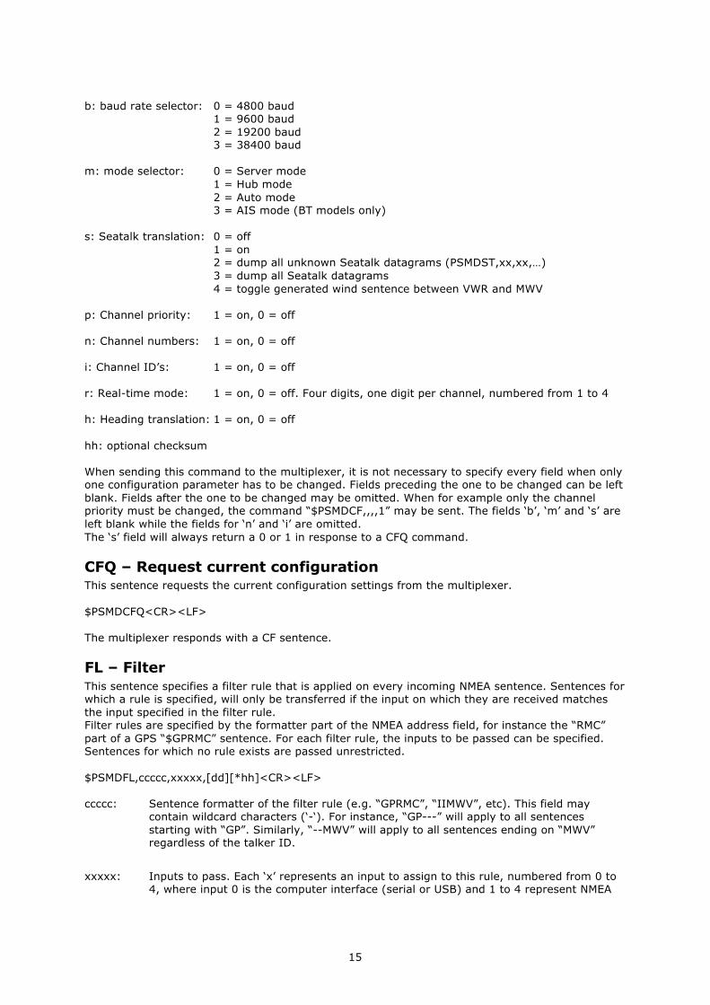
CF – Configuration This sentence sets the configuration of the multiplexer. The same sentence is sent by the multiplexer in response to a CFQ sentence. Command: $PSMDCF,b,m,s[*hh]<CR><LF> (-41 models) $PSMDCF,b,m,s,p,n,i,rrrr,h[*hh]<CR><LF> (-42 models)
15
b: baud rate selector: 0 = 4800 baud 1 = 9600 baud 2 = 19200 baud 3 = 38400 baud m: mode selector: 0 = Server mode 1 = Hub mode 2 = Auto mode 3 = AIS mode (BT models only) s: Seatalk translation: 0 = off 1 = on 2 = dump all unknown Seatalk datagrams (PSMDST,xx,xx,…) 3 = dump all Seatalk datagrams 4 = toggle generated wind sentence between VWR and MWV p: Channel priority: 1 = on, 0 = off n: Channel numbers: 1 = on, 0 = off i: Channel ID’s: 1 = on, 0 = off r: Real-time mode: 1 = on, 0 = off. Four digits, one digit per channel, numbered from 1 to 4 h: Heading translation: 1 = on, 0 = off hh: optional checksum When sending this command to the multiplexer, it is not necessary to specify every field when only one configuration parameter has to be changed. Fields preceding the one to be changed can be left blank. Fields after the one to be changed may be omitted. When for example only the channel priority must be changed, the command “$PSMDCF,,,,1” may be sent. The fields ‘b’, ‘m’ and ‘s’ are left blank while the fields for ‘n’ and ‘i’ are omitted. The ‘s’ field will always return a 0 or 1 in response to a CFQ command.
CFQ – Request current configuration This sentence requests the current configuration settings from the multiplexer. $PSMDCFQ<CR><LF> The multiplexer responds with a CF sentence.
FL – Filter This sentence specifies a filter rule that is applied on every incoming NMEA sentence. Sentences for which a rule is specified, will only be transferred if the input on which they are received matches the input specified in the filter rule. Filter rules are specified by the formatter part of the NMEA address field, for instance the “RMC” part of a GPS “$GPRMC” sentence. For each filter rule, the inputs to be passed can be specified. Sentences for which no rule exists are passed unrestricted. $PSMDFL,ccccc,xxxxx,[dd][*hh]<CR><LF> ccccc: Sentence formatter of the filter rule (e.g. “GPRMC”, “IIMWV”, etc). This field may
contain wildcard characters (‘-‘). For instance, “GP---” will apply to all sentences starting with “GP”. Similarly, “--MWV” will apply to all sentences ending on “MWV” regardless of the talker ID.
xxxxx: Inputs to pass. Each ‘x’ represents an input to assign to this rule, numbered from 0 to
4, where input 0 is the computer interface (serial or USB) and 1 to 4 represent NMEA

16
inputs 1 to 4. A ‘1’ means to pass, a ‘0’ means to block. When all x’es are ‘1’, the filter rule is removed.
dd: Optional divisor factor (0..99). The frequency of a sentence is divided by this number
to reduce the number of sentences in time. If for instance a divisor of 6 is specified for a sentence, only every 6th sentence is passed. This can be used to reduce the output of a high-speed heading sensor.
hh: Optional checksum A FL sentence without any parameters will erase all rules. Example: $PSMDFL,GPRMC,10011<CR><LF> This sentence specifies a rule for all sentences that have the “GPRMC” sentence formatter. When this rule is applied, only “GPRMC” sentences on inputs 0 (the computer), 3 and 4 are transferred. An FL sentence with wildcards on all positions is discarded.
FLQ – Request filter list This sentence requests the filter list from the multiplexer. The multiplexer responds by sending FL sentences, one for each list entry. An empty FL sentence denotes the end of the list. Example:
$PSMDFL,GPRMC,10011,0*hh<CR><LF> $PSMDFL,GPGGA,10001,0*hh<CR><LF> $PSMDFL,--VWT,01000,5*hh<CR><LF> $PSMDFL,GPGSV,00001*hh<CR><LF> $PSMDFL,*hh<CR><LF>
The sentences may not be dumped as one contiguous block. In case of heavy NMEA traffic, they may be interspersed with other NMEA sentences.
ID – Talker ID Enables a Talker ID to be set for a specific channel. If the talker ID is set for a specific channel, the original talker ID in the sentences received on that channel is replaced by the specified one, before sending the sentence to the computer. $PSMDID,aa,bb,cc,dd[*hh]<CR><LF> aa: Talker ID for channel 1 bb: Talker ID for channel 2 cc: Talker ID for channel 3 dd: Talker ID for channel 4 hh: optional checksum An empty field clears the ID and disables the translation for that specific channel. Sending PSMDID without any fields clears all translations.
IDQ – Request talker ID’s Requests the Talker ID Translation settings. The multiplexer responds with an ID sentence.
OV – Overflow In case of a buffer overflow (blinking red LED on the multiplexer), an overflow sentence is output, to indicate on which input buffer the overflow occurred: $PSMDOV,x<CR><LF> x: Binary field. The first four bits indicate on which input buffer the overflow occurred.

17
Translated Seatalk datagrams When the Seatalk translation is enabled, the following datagrams are translated into NMEA sentences: SeaTalk NMEA Description 00 DBT Depth below transducer 10 MWV Wind angle, (10 and 11 combined) 11 MWV Wind speed, (10 and 11 combined) 20 VHW Speed through water 21 VLW Trip mileage (21 and 22 combined) 22 VLW Total mileage (21 and 22 combined) 23 MTW Water temperature 25 VLW Total and Trip mileage 26 VHW Speed through water 27 MTW Water temperature 50 --- Latitude, value stored 51 --- Longitude, value stored 52 --- Speed over ground, value stored 53 RMC Course over ground. RMC sentence is
generated from stored values from 5x datagrams.
54 --- GMT time, value stored 56 --- Date, value stored 58 --- Lat/Long, values stored 89 HDG Magnetic heading, including variation (99) 99 --- Magnetic variation, value stored As appears from the table, not all datagrams result in an NMEA sentence. Some datagrams are only used to retrieve a certain value to be combined into one NMEA sentence. When the Seatalk translation is enabled with option 2 (the ‘s’ parameter in the CF sentence is 2), unlisted datagrams are translated into a proprietary NMEA sentence with the following format: $PSMDST,aa,bb,cc,dd…*hh<CR><LF> aa,bb,cc,dd… represent the hexadecimal value of the bytes from the received Seatalk datagram.
Technical Specifications: Supply voltage: 5VDC from USB bus or
8 – 30 VDC, protected against reversed polarity. Current consumption: 50 mA (100 mA max. with fully loaded talker ports). Inputs: 4 x NMEA-183/RS-422, galvanically isolated. 1 input can be set to SeaTalk mode. Input resistance: >800 Ohm. Outputs: 1 x USB, 2 x NMEA-183/RS-422. Buffers: 5 buffers of 800 characters (4 x NMEA, 1 x RS-232). Filter list size: 30 sentence types Priority list size: 30 sentence types NMEA Out1: Combined data from NMEA inputs. NMEA Out2: Combined data from NMEA and USB inputs (Hub mode) or data from USB input only (Server mode). Speed NMEA in: 4800 Baud. Speed NMEA Out1/USB: 4800, 9600, 19200 or 38400 Baud. Speed NMEA Out2: 4800 Baud. Indicators: Overflow and Data. Dimensions: 138 x 72 x 33 mm. Housing: Flame retardant ABS.

18
Declaration of Conformity
We,
CustomWare Borgstee 27b 9403 TS Assen The Netherlands Tel.: +31 592 375700 Fax: +31 592 375550
Declare under our sole responsibility that the product
ShipModul MiniPlex-42USB
to which this declaration relates is in conformity with the following specifications:
EN/IEC61000-6-1:1997 and EN/IEC61000-6-3:1996 EN/IEC61162-1:2000 FCC Title 47 CFR, Part 15 Class B
The product herewith complies with the requirements of the EMC Directive 89/336/EEC and carries the CE-marking accordingly.
Assen, 19-6-2008 M. Sprang
This device complies with Part 15 of the FCC Rules. Operation is subject to the following conditions: (1) This device may not cause harmful interference, and (2) this device must accept any interference received, including interference that may cause undesired operation.

19
ShipModul / CustomWare Borgstee 27b 9403 TS Assen The Netherlands
Tel.: +31 592 375700 Fax: +31 592 375550
web: www.shipmodul.com e-mail: [email protected]