mining by rock cutting in narrow reefs
TRANSCRIPT

MINING BY ROCK CUTTING IN NARROW REEFS 221
IntroductionThe hard rock gold and platinum mines in South Africahave seen little development in the technology of mining.Holes are still drilled in the rock - though the latest waterhydraulic rockdrills will complete that task in two minutescompared with the eight hours for hammer hand drilling atthe start of the last century. Charging up is with far saferexplosives, and with available initiation systems it is nolonger necessary to run up the face lighting each fuse.Movement of rock in the stope is predominately by meansof scraper buckets and scraper winches - these were firstintroduced in the 1920s. Support is still mainly rock, eitherin situ pillars or backfill, or alternatively wood. As themining process has changed very little, it is hardlysurprising that the productivity of mining is also relativelyunchanged.
Major efforts have been made to mechanize the miningprocess. However, most of the narrow reef mines where‘trackless mechanized mining’ was introduced in the early1980s have reverted to conventional mining. In the widerreefs mechanized mining is the option of choice;unfortunately most of the gold and platinum mines havevery narrow reefs that are not suited to ‘off the shelf’equipment. The move to introduce room and pillar mininginto the narrow UG2 reefs is at the expense of mining morewaste with the reef; fortunately it appears that appropriatewaste and reef separation processes are available. Roomand pillar mining followed by long hole drilling andblasting of a narrow slot of reef out of the pillars currentlyappears to offer the best of both worlds - maximum reefrecovery with minimum waste dilution.
All these mining methods are still dependent on blastingto break the rock. The cyclic nature of mining by blastingplaces severe constraints on the rate of face advance thatcan be achieved and consequently the utilization of theinvested capital. For narrow reef hard rock mining to breakout of these constraints and to really make progress in the21st century, it is necessary to follow the lead of the softrock mining industry and change the technology of mining.In the underground coalmining industry, coal cutting hasbeen proven to be the most cost-effective solution; in
narrow reef hard rock mining the future must be based onthe development of non-explosive methods of rockbreaking that, in turn, are integrated into continuous miningsystems.
Non-explosive mining means that the mining operationcan be conducted on a continuous basis, with no delays forthe removal of blasting fumes. Continuous mining alsomaximizes the return on the capital invested in developingthe mine. Rock cutting will define the stope width and thatin turn will be designed to minimize waste dilution; it willalso minimize damage to the hanging and create a saferenvironment. Mechanization makes it possible to automatethe mining process and further improve safety bypositioning the operators in a safer environment.
Over the years there have been trials of a number ofdifferent cutting processes and mining machines:
• Typically cutting with picks has not been cost-effectivein hard rock.
• It is well known that full-face cutting with either soliddiscs or cutters has been successfully applied to raiseboring and TBMs. A narrow reef mining machineoperating with this cutting mode has been developedand trialed by Placer Dome in a narrow veinunderground in Canada, and a similar machine wastrialed by Anglo Platinum. Cutting experience islimited, with only a few cubic metres of rock cut atboth sites.
• Anglo Platinum used activated cutting for a stopingmachine in the platinum mines and have successfullycut a few cubic metres.
• CRC Mining in Brisbane is conducting laboratory -scale experiments for oscillating disc cutting and therehas been some cutting in a quarry.
• Undercutting, as a cutting process, was used by Wirthin the mobile tunnelling machine that mined about 200m3 in a Sudbury mine. It is now used by SMC in theARM 1100 and has successfully cut over 5 000 m3 inboth the UG2 and Merensky reefs.
This paper defines the work to evaluate cutting processescarried out by Sandvik; the introduction of the machine intoa Lonmin Platinum mine; the performance achieved; and
PICKERING, R., SMIT, A. and MOXHAM, K. Mining by rock cutting in narrow reefs. International Platinum Conference ‘Platinum Surges Ahead’, TheSouthern African Institute of Mining and Metallurgy, 2006.
Mining by rock cutting in narrow reefs
R. PICKERING*, A. SMIT* and K. MOXHAM†
*Sandvik†Lonmin Platinum
Since the early 1970s research has been ongoing to develop a cost-effective way of continuouslymining the narrow reef, hard rock, typical of South African gold and platinum mines. In the late1980s it was shown that impact ripping was a practical solution for the deep gold mines. In March2001 Lonmin and Sandvik agreed to co-operate in an endeavour to design and manufacture aprototype narrow reef mining machine with the ultimate aim of producing such a machine on acommercial basis that would enable Lonmin to create a safer and more productive environmentwithin its mines and for Sandvik to enhance its leading position as a supplier of a new generationhard rock cutting machine. This paper describes the developed technology, the current progress ofthe delivery of the required objectives and the optimum mining layout for the roll-out of themining method.

PLATINUM SURGES AHEAD222
the current proposed mining layout for implementation ofthe ARM 1100 as a mining production tool.
BackgroundVoest Alpine Bergtechnik is an Austrian Company based inZeltweg in Austria. They have had extensive experience inrock cutting and for many years they have designed andmanufactured road headers and tunnel boring machines.During the late 1990s they, together with Sandvik Tamrock,were major players in the development of the Icutrocprocess. This development made it possible for pick cuttingmachines to operate cost-effectively in substantially harderground.
Initial trialsTowards the end of 1998 developments in the platinumindustry were pointing the direction for massive change inthe narrow reef mining processes. A number of mechanizedmining methods were being evaluated, together with onenon-explosive based mining system. Voest Alpine hadalready applied the Icutroc cutting process in the StillwaterPalladium Mine in Montana, with mixed results. However,the UG2 was regarded as an easier target and it was decidedthat the most appropriate start was to carry out pick cuttingtests, in Austria, on a sample block of UG2 reef.
The reef was sourced from the Anglo Platinum Mine,Union Section, it had a low uniaxial compressive strengthof 26 MPa; the sample also contained waste bands ofpyroxenite with a UCS of 110 MPa. However, the Chercharabrasivity index for the chromite ore was 5.4. This is anindication of the extreme abrasivity of the UG2 reef, on apar with high quality quartzite.
The cutting tests were conducted with a variety of carbidecutting tools and at various speeds and depths of cut. Thesurprising result from the trials was the very low pick life,with the best available picks being severely damaged afteronly four passes over the UG2 reef. It is believed that thehigh wear rates were not a function of the uniaxialcompressive strength (UCS) of the UG2 but rather thehardness and abrasivity of the chromite crystals that makeup the structure of the UG2
Phase II testingIf pick cutting could not provide the answer, it was decidedthat the practicality of disc cutting should be reviewed.Voest Alpine have participated in various trials of activatedcutting, using the Bechem process, and have closelyevaluated the oscillating disc cutter currently undergoingtrials in Australia. The benefit to be achieved fromactivating or oscillating disc cutting was considered to bequestionable and the technological hurdles to develop
effective bearings and seals substantial. It was decided thatthe most cost-effective option for reef cutting would beconventional disc cutting technology.
A second rock sample was sent to Austria. This was apyroxenite/norite rock with an UCS of up to 140 MPa,typical of the rock comprising the Merenksy Reef. Thesamples were cast into a concrete block having dimensionsof 4 m � 3 m � 3 m.
Three 300 mm diameter disc cutters were mounted on anABM 105 roadheader. The configuration of the discs andthe cutting action generated a slot 800 mm high and 240mm deep in the side of the test block. The test machine wasextensively instrumented. Analysis of the test results clearlyshowed that the disc cutting closest to the free faceconsumed the lowest power, generated the lowest force andcreated the largest rock particles.
Theory of disc cuttingMechanical rock failure is a complex process influenced bynearly all rock physical and geological properties. Thedominant mode of failure is still a subject of research. Oneaspect shared by all the theories is the existence of a zoneof highly crushed rock material beneath the cutter tip priorto chipping. As the cutter penetrates the rock, a pressurebulb or crushed zone is formed due to the extremely highstresses generated in the rock under the tip of the cutter.The pressure in the crushed zone causes tensile cracks toinitiate and propagate into the rock mass. If the stressesdeveloped in the crushed zone are sufficiently high, one ormore cracks extend far enough to reach one of the tensilecracks developed from an adjacent cut, or alternatively afree face. In conventional disc cutting, rock failure is in theform of chipping. In undercutting the crack propagation isto a free face and rock fragments generated are substantiallylarger. Figure 1 shows conventional disc cutting and discorientation for undercutting
Partnership and high risk itemsUp to this stage in the development of the reef minerSandvik Tamrock and Voest Alpine had worked alone. Itwas recognized that it was now imperative that they enterinto a partnership with a platinum mining company.Presentations were made to the three primary platinumproducing companies in South Africa. One of thesecompanies expressed no interest, a second was interestedbut unwilling to contribute to the cost of the first prototype,and the third company was Lonmin Platinum. Theywholeheartedly supported the concept, and SandvikTamrock, Voest Alpine and Lonmin Platinum entered intoan agreement to develop and trial the Reef Miner. The basicagreement consisted of the following components.
Figure 1. Theoretical rock breaking process for conventional disc cutting and disc orientation for undercutting

MINING BY ROCK CUTTING IN NARROW REEFS 223
• Narrow reef miner design. Sandvik Tamrock andVoest Alpine would design the prototype narrow reefminer entirely at their cost. They would own theintellectual property arising from the design of theprototype.
• Narrow reef miner manufacture. Lonmin Platinumagreed to fund the cost of manufacturing the prototype.This prototype was manufactured in Zeltweg, tested ina representative manner in a concrete block, modifiedas and where necessary and shipped to South Africa.The design and manufacture schedule was estimated tobe twelve months and the prototype machine wasdelivered to South Africa in November 2001.
• High risk elements. Throughout the discussionsbetween Lonmin Platinum, Voest Alpine and SandvikTamrock it has been emphasized that the reef minermakes use of existing technology. The variouscomponents of the basic machine concept are all triedand tested. Examples are in Figures 2 and 3.However, discussion has identified two high-riskelements, either of which could cause failure of thenarrow reef miner to achieve the desired objectives.
• Cutter life and consequently cutter cost per ton isthe major technological issue. The technology of hardrock cutting is well understood and there is extensiveexperience of TBMs using disc cutters, with andwithout carbide inserts. The reef miner uses disc cuttersin an undercutting mode of which there is limitedexperience.The feasibility of developing a test rig has beeninvestigated. Such a rig would have to operate in amine and provide quantitative information on cutterperformance. However, such a test rig would have to beas stiff as the prototype machine and have a similarcutting action. In other words, it would have to be
substantially the same as the prototype machine. It hasbeen concluded that the limited benefits from such atest did not justify the investment in time or money.The issue of cutter life has been addressed from a moretheoretical basis; trials of single cutter discs operatingin an undercutting mode have been carried out and usehas been made of available design expertise in thepractical application of discs operating in anundercutting mode.
• Mining operations and the integration of the reefminer into the mine activities. The introduction oftechnology change on a mine is always difficult and inthis project change will affect everyone from seniormanagement to operational staff. The planning of theimmediate project will be a trivial issue whencompared to the large scale introduction of the ReefMiner. In VAB’s experience other mine activities cantake up as much as 70% of the available time, limitingthe machine operating time to 30% of total time. Goodoperational controls by the mine will result insubstantially increased machine operating time.
Underground trial
Rowland shaftFigure 4 shows the ARM 1100 test site at Rowland shaft.The cutting trial commenced in January 2002 on 25 Levelwith the first cut made on February. The first six months ofthe trial was spent on testing different cutting set-ups andcutter discs and a total of 25 metres was achieved in theperiod up to July 17. At this point the trial was stopped andnew cutters were ordered and modifications to the machinewere undertaken. Cutting recommenced in the first week ofOctober and a further 40 metres were cut in the period tothe first week in November. By the end of January 2003 themachine had cut a total advance of 100 metres. Each metrecut has a cross-section of 1.1 metres high by 4.25 metreswide and thus a one metre advance is equivalent to cuttingjust over 4.5 m3.
The trial team consisted of the following fulltimepersonnel:
1 Artisan/operator — Western Platinum Mine2 Technicians — VAB 1 Technician — Sandvik Tamrock
The full-time team had been supplemented by thefollowing personnel:
1 Manager/Engineer — VAB (60% of the time)1 Technician — Sandvik (80% of the time)
Figure 3. Turret high load bearing from roadheader
Figure 2. Cutter head gearbox from roadheader
Figure 4. Rowland Shaft ARM 1100 test venue

PLATINUM SURGES AHEAD224
The trial site was well prepared and the level ofassistance from Rowland management and personnel washigh.
The structure of the orebody at the trial site is reasonablyconsistent, however, the hardness of the material isrelatively high and therefore a good test for the cuttingability of the machine. See Figure 5.
The ARM was installed on the east side of a raise/winzeconnection and was cutting from the solid face to the freeface in the raise. The cutting plan being to cut up dip for adistance of approximately 70 metres and then turn themachine around and cut down dip for 80 metres. Oncecompleted, the ability of the machine to take a blind cut in astrike direction was tested. Figure 6 shows some early
Figure 5. Typical cut face in UG2 and detail of footwall contact
Figure 6. Assembly of the ARM 1100, launching the machine and cutting into the raise
Figure 8. Scoop used to load cut rock onto the belt conveyor
Figure 7. Different carbide profiles tested on the machine

MINING BY ROCK CUTTING IN NARROW REEFS 225
pictures of the machine underground.
Cutter configurationAfter operating parameters were set, different cutter discdesigns were tested. Cutters tested were manufactured withvarying angles of attack, different bearing designs anddifferent cutting edges as shown in Figure 7.
After extensive testing of various disc cutters, the bestdesign was selected and it was decided to manufactureaccording to this design with varying tungsten carbidegrades on the inserts.
Cleaning system modificationsDuring this time the cleaning mechanisms were evaluatedand modified to improve the effectiveness of rock removalfrom the face. Early examples of the different rock removalsystem are shown in Figure 8.
Machine performanceDuring the period from start-up to end of July 2002 lowdaily cutting rates were achieved, week 24 (10 to 16 June)is typical. (Figure 9.)
Following the start-up after modifications at the end ofSeptember, advance rates increased to a maximum of 3metres per shift. This can be seen in the performance chartsfor week 40 (30 September to 6t October 2002.) (Figure10.)
This performance improved to 4.57 metres per shiftachieved on November 2, 2002, an achievement repeatedthe following week. (Figure 11.)
Rock cut in this period was UG 2 Reef with a UCS of upto 120 MPa and hangingwall and footwall pyroxenites withUCS of around 140 MPa. The reef in the area dips between4.5 and 7 degrees.
Findings — ARM Machine Over 500 cuts have been recorded to date, by means of the
on board data-recording system, and evaluated. Informationhas thus been collected on the following:
• cutter arm slewing force• cutterhead power consumption• cutter arm slewing speed and mean penetration• advance per cut• number of cutterhead stalls.This information obtained to date has been used to
determine the most suitable cutting geometry and thedetermination of optimum cutting parameters.
With the cutter arm force set at 230 kN the cutter headdoes not stall, however, cutter head penetration is limitedby depth of cut. Figure 12 is an example of the detailedanalysis carried out and shows how penetration and depthof cut are related for different carbide and cutterconfigurations.
However, the fracture mechanics of the rock breakingprocess limit the depth of cut that can be achieved. Figure13 shows effective undercutting in the UG2 at RowlandShaft with a maximum depth of cut of 50 mm and howundercutting with the current cutter design becomesineffectual as depth of cut is increased.
Cutter performanceDuring the trial period 11 different cutter types and twodifferent cutter heads have been tested and evaluated. Thecutters tested differed in three basic areas; these are:
• button orientation (15° and 20°)• shape of buttons/cutting edges (conical buttons, chisel
type buttons, steel rings)• bearing configurations• angle of cutter axis.To date 15° conical button cutters have performed the
best in terms of wear, performance (performance beingdefined as cutting rate) and material produced (more chipsand fewer fines). Steel ring cutters performed better andproduced better material but wore out extremely quickly.
A significant difference in chip size, and consequently
Figure 10. Advanced rate, week 40
Figure 9. Advanced rate, week 24

PLATINUM SURGES AHEAD226
specific energy, was realized from different cutter types.(Figure 14.)
• The biggest chips and lowest volume of fines wereproduced with the steel ring cutter.
• The smallest chips and highest volumes of fines weregenerated by the conical buttons.
• The chisel shaped buttons produced fragmentation sizessomewhere in between the other two cutters.
The first set of 15° conical button cutters lasted 15 metresand could have performed better had it not been for brokenbuttons, a problem that seems to have been rectified withthe latest cutters with the insertion of copper shims in theseat of the button. The latest button cutters have achieved30 metres with button wear of approximately 30%. Cuttertests aimed at finding the best grade of tungsten carbide forthe button inserts have been carried out as shown in Figure 15.
CutterheadThe original cutter head was designed and manufacturedwith six cutter discs. It was determined early on in the trialthat more cutters on the head will result in a smoother andmore effective cutting process. A new cutting head wasbuilt and installed in the middle of July and it proved to be
a better option with higher slewing speed and greater depthsof cuts being achieved.
ARM 1100 development targetsIn a development project of this nature it is important to setclear milestones, both from a technological view and from aproduction performance view. For the ARM 1100 thefollowing different phases or targets were established.
Phase IThe first has been completed and consisted ofdemonstrating that the ARM 1100 worked. A realisticpotential production level was established and preliminarycutter performance determined. The machine can completean advance of 850 mm in sixty minutes. Carbide rings havedemonstrated a life of 30 metres advance with only 5.5 mmof wear.
Phase IIThe first part of this phase the project was completed in2004 and the deliverable at the end of this phase had beendetermined to be as follows:
Figure 11. Advance rate, Week 44
Figure 12. Effective penetration against depth of cut

MINING BY ROCK CUTTING IN NARROW REEFS 227
• ARM 1100 performance of achieving a shift advancerate of 3 metres per shift, for 70% of the available shiftsfor a period of one month. In a twenty-two shift monththis equates to a monthly advance of 65 metres.Resolved issues considered to be getting in the way ofachieving this objective were:• A system of ore handling in the cutting area that
would successfully remove +90% of the rock brokenper cut
• A rock handling system to move broken rock from theARM 1100 machine to the mine rock handlinginfrastructure
• Development and integration of a support installationsystem
• A cutter test programme to demonstrate cutter ring setlife equivalent to seventy-five metres and bearing lifeof two hundred metres. This objective has not beenachieved.
Phase III
The deliverable at the end of Phase III is greater confidencein the total system performance in terms of production andcutter cost. The specific objectives are as follows:
• Continuous cutting of the ARM 1100 on a two-shiftbasis for a period of one month. Assuming twenty twodays per month and two shifts per day, the advance ratewill be 187 metres per month.
• The cutter test programme must demonstrate cutter ringset life of one hundred metres and a bearing life ofthree hundred metres. This would result in a cutter costof R56-00 per ton. Demonstration of this objectivewould require at least 375 metres of cutting.
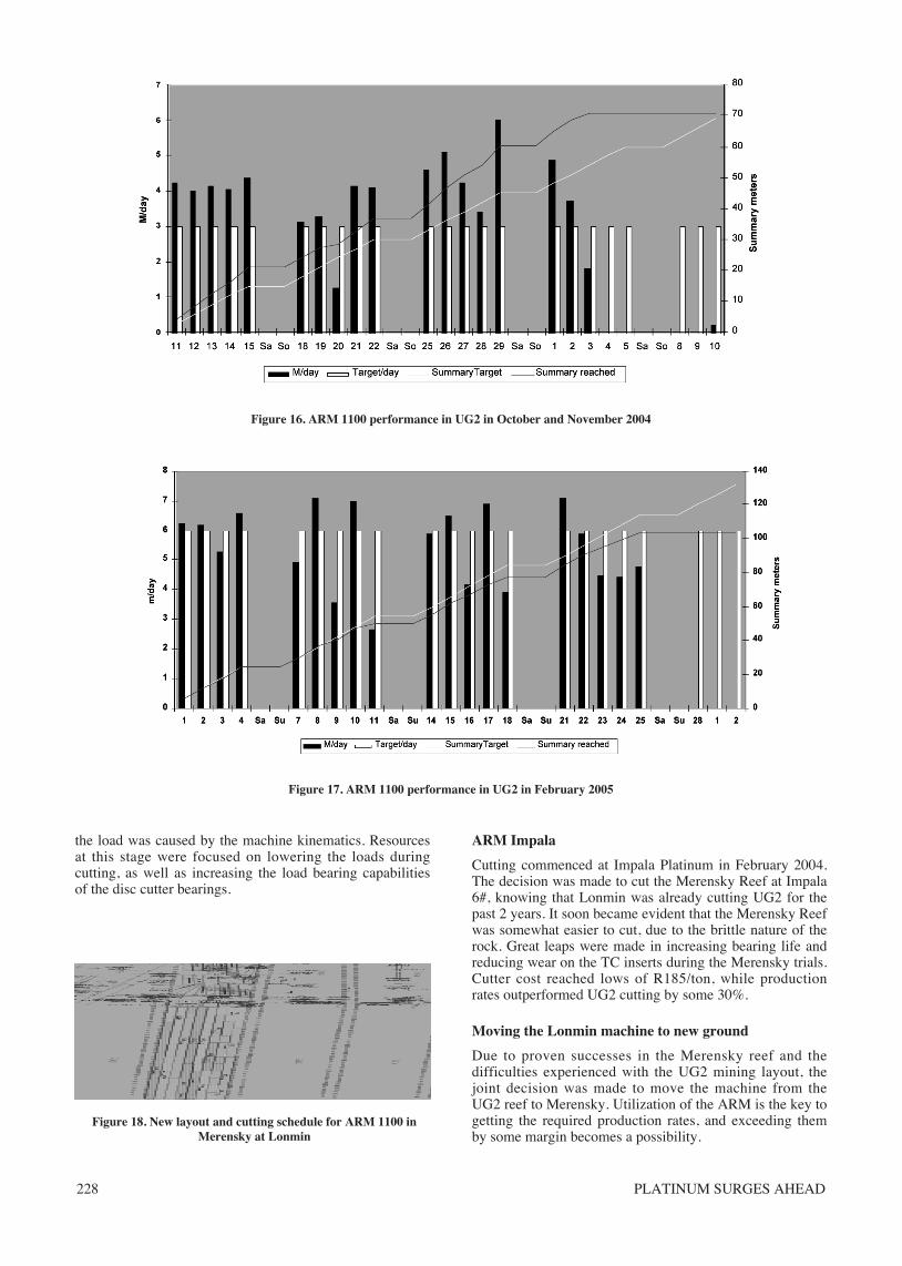
Production trial 2004–2005In October 2004, single shift production trials commenced.The aim was to cut 3 m per day for 22 days a month. Thiswould yield a 276 centare production month. Both theOctober and November trials were successful in yielding280 centares in 17 shifts. (Figure 16.)
The next target was to achieve a production call of 3 mper shift for 22 shifts on a 2-shift basis. (Figure 17.)
This trial was ended prematurely as the stope ventilationin a blind cut was inadequate. The tipping point was too farfor an XLP loader to make the round trips in time, andtemperatures in the stope due to the ‘blind cut’ situationexceeded 36ºC wet bulb.
During this period, extensive cutter load measurementswere done on the machine in the actual miningenvironment. The load measurements were made possibledue to advances in memory card technology in recent years.The cutter load measurements revealed the actual loadsencountered on the cutters during a cutting cycle as well asmaking it possible to identify where the loads weregenerated. 50% of the load on a cutter was used to cut, 40%was used to move ore collecting on the footwall and 10% ofFigure 12. Different TC inserts tested
Figure 13. Effective undercutting with varying depth of cut, and with increased depth of cut undercutting ceases
Chips from steelring cutters Chips from chisel-type cutters Chips from 20° conical button
Figure 14. Rock fragmentation produced from different cutter configuration
PLATINUM SURGES AHEAD228
the load was caused by the machine kinematics. Resourcesat this stage were focused on lowering the loads duringcutting, as well as increasing the load bearing capabilitiesof the disc cutter bearings.
ARM Impala
Cutting commenced at Impala Platinum in February 2004.The decision was made to cut the Merensky Reef at Impala6#, knowing that Lonmin was already cutting UG2 for thepast 2 years. It soon became evident that the Merensky Reefwas somewhat easier to cut, due to the brittle nature of therock. Great leaps were made in increasing bearing life andreducing wear on the TC inserts during the Merensky trials.Cutter cost reached lows of R185/ton, while productionrates outperformed UG2 cutting by some 30%.
Moving the Lonmin machine to new ground
Due to proven successes in the Merensky reef and thedifficulties experienced with the UG2 mining layout, thejoint decision was made to move the machine from theUG2 reef to Merensky. Utilization of the ARM is the key togetting the required production rates, and exceeding themby some margin becomes a possibility.
Figure 17. ARM 1100 performance in UG2 in February 2005
Figure 16. ARM 1100 performance in UG2 in October and November 2004
Figure 18. New layout and cutting schedule for ARM 1100 inMerensky at Lonmin

MINING BY ROCK CUTTING IN NARROW REEFS 229
Performance drivers and the future
Mining layoutThe mining layout is essential in achieving productiontargets. Conventional mining lay outs are altered to producethe highest yield in production. Layout requirements are:
• The section needs to be as long as possible, preferablyin a strike direction
• Any blasted areas such as gullys and SPDs would causea substantial loss in production, due to instability of themachine in these areas
• Tipping points should be no further than 130 m fromthe machine at any stage in the production process
• Through ventilation in the section would be preferable,but is not a necessity.
The current layout for the machine being installed atLonmin is shown in Figure 18 and is as follows.
• The machine will cut up and down dip, in a 260 mlong, force ventilated stope with only one tipping pointat the up-dip side of the stope.
• Ore handling will be done through multiple shuttlecars, handling ore at the machine, transferring it toshuttle cars moving between the machine and the tips.
• Ventilation will be forced up to the machine, where itwill be exhausted from the machine to be scrubbed at aremote location further up in the stope.
In short, this mining lay out utilizes the ‘half level’ layoutthat Rowland Shaft currently has. There is no need forblasting a gully, as ore is handled via shuttle cars. Ore willstill be tipped into conventional box-holes. The shuttle carswill be electrically driven, eliminating any disruption in themine’s current ventilation set up as well as eliminating theuse of scraper winches.
Each machine will deliver in excess of 5 000 tons permonth with a crew of 7.5 per machine, includingsupervisory personnel for a multiple machine layout, and 9crew members for a single machine layout.
Ore handlingFor cutting processes able to do their own development, orehandling must be fast, flexible and clean. A lot of time hasbeen spent on refining the ore handling system, using anarray of media in trying to achieve the final solution. Usingconveyors as an ore handling medium had its restrictions.The possibility of utilizing an extendable conveyor in a 1.1m height stope, proved to be ineffective. More time wasspent moving and extending conveyors, leaving less thandesirable production time. Due to the ARM being able to doits own development, conveyors are not able to follow themachine into ‘blind cuts’, cut away from a tipping point or
change direction within the stope. A more flexible system isparamount to the ARM’s production output. Currently themachine of choice is the EJC 88 but, due to lack offlexibility and exhaust emissions, further developments areunderway. The final solution will be either battery driven orelectrically powered with flexibility for bunkering andtransport.
Sandvik Mining and Construction is in the process ofdeveloping a machine-specific solution for the ARM’s orehandling needs. This system will cater for layoutsdemanding a high level of flexibility and speed. A multiplebucket system is under consideration. Buckets will be ableto contain ore generated from two or more consecutive cuts.The bucket will be placed behind the ARM’s conveyor. Ahydraulic mechanism will move the bucket a set distanceafter each cut, to ensure that the ore is spread evenly overthe length of the bucket so as to prevent spillage. Thebucket will then be picked up by a bucket shunting machineand placed on a multiple bucket carrier. Once the bucket isloaded on the carrier, the shunter will place the next bucketbehind the conveyor, before the next batch of ore isdelivered. The bucket carrier machine will be able to handlethree or more buckets, effectively carrying six or morecomplete cuts (6.5 tons). The bucket carrier machine has amaximum of 9 minutes to dump the three containers at thetip and return back to the machine. While the bucket carrieris away, the bucket shunter will place the filled buckets onthe footwall. With 9 or more buckets in circulation,temporary bunkering of ore will be possible, ensuring nointerruption in production of the ARM. (See Figure 19.)
In applicable future mining layouts, it will be possible tore-employ the scraper winch as the primary ore handlingsystem due to its simplicity, cost and flexibility. The systemwill require the stope to be re aligned with tipping points, toensure that the scraper winch will be pulling ore up to thetip alongside the section pillar. Due to the profile of theARM’s cut, the scraper winch will run on the footwall,eliminating the need for the normally associated gullyprofile. An LHD will be used to collect the ore from theback of the ARM conveyor. The ore will then be tipped inthe path of the continuously running scraper winch. Withthe needed access restrictions in the section, the winch canbe fully automated as well as the LHD. Cyclic use ofadjacent sections will allow the support of a 4 m effectiveface advance to be delayed. Bolting of the previous cut willcommence once the ARM is cutting in an adjacent section.This will eliminate the need for an on-board bolter,replacing 3 bolters with one. No operators will be needed atthe machine while cutting is in operation, thereby achievingfully remote operation.
Figure 19. Possible new ore handling systems to complement the ARM 1100

MINING BY ROCK CUTTING IN NARROW REEFS 230
Comment
Optimizing production Today, the ARM can produce a production figure of 4.2m3/hour. By optimizing the mining layout to keep the ARMcontinuously cutting, utilization figures of 75% can besustainably achieved. Utilizing 24 hours per day,production levels of 1 900 centares per month will bepossible. Only further development of the machine and disccutters is needed to increase this figure continuously.
Optimizing mining cost The total labour cost portion of the ARM system totals 12%at full production. Only 7.5 crew members are needed toproduce 7 000 tons per month. ARM cutter cost comprises55% of the total Mining cost at full production. This wouldmean that mining cost can now be driven by advances incutter technology rather than labour cost and its associatedeffects.
Optimizing ore reserve dilution Although difficult to quantify, the gains to be made with astoping system that self-develops is real. Based on currentmining layouts for Lonmin, the total development neededper 1 000 m2 of stoping, is in the order of 12.5 m. Thisfigure includes haulage, workshop, box hole and slusherdevelopment. Through developing haulages on reef, thisfigure will dilute to 5.5 m/1 000 m2.
Optimizing ore reserves
Due to the safe and non-destructive mining action of theARM, ore reserves previously known as ‘not suitable tomine due to ground conditions’ can now be added to the orereserve capacity. This will have an adverse effect on thelifetime expectancy of ore reserves.
ConclusionThe move to rock cutting and continuous mining is seen asthe ultimate objective for many underground hard rockmining practitioners. The challenge is to develop a workingmachine, followed by a cost-effective mining system.Sandvik Lonmin and Impala are very close to achieving thisobjective after a number of years’ work. Total cutting inSouth African platinum mines exceeds 7 200 m3 and thereis additional experience from cutting in a Polish coppermine.
Placer Dome has also developed a narrow reef hard rockmining machine at a cost of some $20 million. The machinehas operated in an underground stope and cut somehundreds of cubic metres.
The activated disc cutter machine developed by the CSIR,Anglo Platinum and Long Airdox has cut a few cubicmetres in a narrow stope.
The oscillating disc cutter is seen by some as the possiblebasis for a hard rock cutting machine. To date experience islimited to laboratory trials and limited cutting in a quarry.